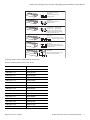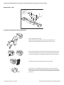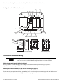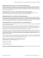
1
Guardmaster® Safedge™
Pressure Sensitive Safety Edge System
Installation and User Manual
440F
Original Instructions in English
Guardmaster® Safedge Pressure Sensitive Safety Edge System Installation and User Manual
Important User Information
Because of the variety of uses for the products described in this publication, those responsible for the
application and use of this control equipment must satisfy themselves that all necessary steps have been
taken to assure that each application and use meets all performance and safety requirements, including
any applicable laws, regulations, codes and standards.
The illustrations, charts, sample programs and layout examples shown in the guide are intended solely for
purposes of example. Since there are many variables and requirements associated with any particular
installation, Rockwell Automation does not assume responsibility or liability (to include intellectual property
liability) for actual use based upon the examples shown in this publication.
Rockwell Automation publication SGI-1.1, Safety Guidelines for the Application, Installation and
Maintenance of Solid-State Control (available from your local Rockwell Automation sales office), describes
some important differences between solid-state equipment and electromechanical devices that should be
taken into consideration when applying products such as those described in this publication.
Reproduction of the contents of this copyrighted publication, in whole or part, without written permission
of Rockwell Automation, is prohibited.
Throughout this manual we use notes to make you aware of safety considerations:
WARNING
IMPORTANT
ATTENTION
Identifies information about practices or circumstances that can cause an explosion in
a hazardous environment, which may lead to personal injury or death, property
damage, or economic loss.
Identifies information that is critical for successful application and understanding of
the product.
Identifies information about practices or circumstances that can lead to personal
injury or death, property damage, or economic loss. Attentions help you identify a
hazard, avoid a hazard, and recognize the consequences.
SHOCK HAZARD
Labels may be on or inside the equipment (for example, drive or motor) to alert people
that dangerous voltage may be present.
BURN HAZARD
Labels may be on or inside the equipment (for example, drive or motor) to alert people
that surfaces may reach dangerous temperatures.
It is recommended that you save this user manual for future use.
2
Original Instructions in English
Rockwell Automation Publication 440F-UM002A-EN-P
Guardmaster® Safedge Pressure Sensitive Safety Edge System Installation and User Manual
Table of Contents
Introduction . . . . . . . . . . . . . . . . . . . . . . . . . . . . . . . . . . . . . . . . . . . . . . . . . . . . . . . . . . . . . . . . . . . . . . . . . . . . . . . . . . . . . . . . . . . . . . . . . . . . . . . . . . . . . . . . . . . . . . . . . . . . . . . . .4
System Description . . . . . . . . . . . . . . . . . . . . . . . . . . . . . . . . . . . . . . . . . . . . . . . . . . . . . . . . . . . . . . . . . . . . . . . . . . . . . . . . . . . . . . . . . . . . . . . . . . . . . . . . . . . . . . . . . . . . . . . . . . .4
Storage and Handling . . . . . . . . . . . . . . . . . . . . . . . . . . . . . . . . . . . . . . . . . . . . . . . . . . . . . . . . . . . . . . . . . . . . . . . . . . . . . . . . . . . . . . . . . . . . . . . . . . . . . . . . . . . . . . . . . . . . . . . .4
Storage. . . . . . . . . . . . . . . . . . . . . . . . . . . . . . . . . . . . . . . . . . . . . . . . . . . . . . . . . . . . . . . . . . . . . . . . . . . . . . . . . . . . . . . . . . . . . . . . . . . . . . . . . . . . . . . . . . . . . . . . . . . . . . . . . .4
Handling and Transport . . . . . . . . . . . . . . . . . . . . . . . . . . . . . . . . . . . . . . . . . . . . . . . . . . . . . . . . . . . . . . . . . . . . . . . . . . . . . . . . . . . . . . . . . . . . . . . . . . . . . . . . . . . . . . . . . .4
Safedge Selection . . . . . . . . . . . . . . . . . . . . . . . . . . . . . . . . . . . . . . . . . . . . . . . . . . . . . . . . . . . . . . . . . . . . . . . . . . . . . . . . . . . . . . . . . . . . . . . . . . . . . . . . . . . . . . . . . . . . . . .5
Selection Procedure . . . . . . . . . . . . . . . . . . . . . . . . . . . . . . . . . . . . . . . . . . . . . . . . . . . . . . . . . . . . . . . . . . . . . . . . . . . . . . . . . . . . . . . . . . . . . . . . . . . . . . . . . . . . . . . . . . . . .5
Safedge Profiles . . . . . . . . . . . . . . . . . . . . . . . . . . . . . . . . . . . . . . . . . . . . . . . . . . . . . . . . . . . . . . . . . . . . . . . . . . . . . . . . . . . . . . . . . . . . . . . . . . . . . . . . . . . . . . . . . . . . . . . . .6
Installation of the Safedge System . . . . . . . . . . . . . . . . . . . . . . . . . . . . . . . . . . . . . . . . . . . . . . . . . . . . . . . . . . . . . . . . . . . . . . . . . . . . . . . . . . . . . . . . . . . . . . . . . . . . . . . . . . . .9
Installation of “C” Rail . . . . . . . . . . . . . . . . . . . . . . . . . . . . . . . . . . . . . . . . . . . . . . . . . . . . . . . . . . . . . . . . . . . . . . . . . . . . . . . . . . . . . . . . . . . . . . . . . . . . . . . . . . . . . . . . . . . .9
Mounting the “C” Rail . . . . . . . . . . . . . . . . . . . . . . . . . . . . . . . . . . . . . . . . . . . . . . . . . . . . . . . . . . . . . . . . . . . . . . . . . . . . . . . . . . . . . . . . . . . . . . . . . . . . . . . . . . . . . . . . . .10
Assembly and Installation of the Safedge Profile . . . . . . . . . . . . . . . . . . . . . . . . . . . . . . . . . . . . . . . . . . . . . . . . . . . . . . . . . . . . . . . . . . . . . . . . . . . . . . . . . . . . . . . . .10
Sensing Surface of Safedge System. . . . . . . . . . . . . . . . . . . . . . . . . . . . . . . . . . . . . . . . . . . . . . . . . . . . . . . . . . . . . . . . . . . . . . . . . . . . . . . . . . . . . . . . . . . . . . . . . . . . . .11
Control Unit Technical Specifications . . . . . . . . . . . . . . . . . . . . . . . . . . . . . . . . . . . . . . . . . . . . . . . . . . . . . . . . . . . . . . . . . . . . . . . . . . . . . . . . . . . . . . . . . . . . . . . . . . . .12
Force Travel Relationship. . . . . . . . . . . . . . . . . . . . . . . . . . . . . . . . . . . . . . . . . . . . . . . . . . . . . . . . . . . . . . . . . . . . . . . . . . . . . . . . . . . . . . . . . . . . . . . . . . . . . . . . . . .13
Deformation Travels . . . . . . . . . . . . . . . . . . . . . . . . . . . . . . . . . . . . . . . . . . . . . . . . . . . . . . . . . . . . . . . . . . . . . . . . . . . . . . . . . . . . . . . . . . . . . . . . . . . . . . . . . . . . . . .13
Selecting the Cushion Factor . . . . . . . . . . . . . . . . . . . . . . . . . . . . . . . . . . . . . . . . . . . . . . . . . . . . . . . . . . . . . . . . . . . . . . . . . . . . . . . . . . . . . . . . . . . . . . . . . . . . . . .15
Mounting . . . . . . . . . . . . . . . . . . . . . . . . . . . . . . . . . . . . . . . . . . . . . . . . . . . . . . . . . . . . . . . . . . . . . . . . . . . . . . . . . . . . . . . . . . . . . . . . . . . . . . . . . . . . . . . . . . . . . . . . .15
Terminal Connections . . . . . . . . . . . . . . . . . . . . . . . . . . . . . . . . . . . . . . . . . . . . . . . . . . . . . . . . . . . . . . . . . . . . . . . . . . . . . . . . . . . . . . . . . . . . . . . . . . . . . . . . . . . . .15
Safedge Control Unit: Electrical Connections . . . . . . . . . . . . . . . . . . . . . . . . . . . . . . . . . . . . . . . . . . . . . . . . . . . . . . . . . . . . . . . . . . . . . . . . . . . . . . . . . . . . . . . . . . . . . . . . .16
Control Unit Installation and Wiring . . . . . . . . . . . . . . . . . . . . . . . . . . . . . . . . . . . . . . . . . . . . . . . . . . . . . . . . . . . . . . . . . . . . . . . . . . . . . . . . . . . . . . . . . . . . . . . . . . . . . . . . .16
Main selector switch . . . . . . . . . . . . . . . . . . . . . . . . . . . . . . . . . . . . . . . . . . . . . . . . . . . . . . . . . . . . . . . . . . . . . . . . . . . . . . . . . . . . . . . . . . . . . . . . . . . . . . . . . . . . . . .16
Main input terminal. . . . . . . . . . . . . . . . . . . . . . . . . . . . . . . . . . . . . . . . . . . . . . . . . . . . . . . . . . . . . . . . . . . . . . . . . . . . . . . . . . . . . . . . . . . . . . . . . . . . . . . . . . . . . . . .16
24V AC/DC input terminal +ve and -ve . . . . . . . . . . . . . . . . . . . . . . . . . . . . . . . . . . . . . . . . . . . . . . . . . . . . . . . . . . . . . . . . . . . . . . . . . . . . . . . . . . . . . . . . . . . . .17
Auxiliary Output terminals 31 and 32 . . . . . . . . . . . . . . . . . . . . . . . . . . . . . . . . . . . . . . . . . . . . . . . . . . . . . . . . . . . . . . . . . . . . . . . . . . . . . . . . . . . . . . . . . . . . . .17
Safety Output terminals 13, 14, 23 and 24 . . . . . . . . . . . . . . . . . . . . . . . . . . . . . . . . . . . . . . . . . . . . . . . . . . . . . . . . . . . . . . . . . . . . . . . . . . . . . . . . . . . . . . . . . .17
Reset terminal MC-MC . . . . . . . . . . . . . . . . . . . . . . . . . . . . . . . . . . . . . . . . . . . . . . . . . . . . . . . . . . . . . . . . . . . . . . . . . . . . . . . . . . . . . . . . . . . . . . . . . . . . . . . . . . . . .17
Profile connection to control units . . . . . . . . . . . . . . . . . . . . . . . . . . . . . . . . . . . . . . . . . . . . . . . . . . . . . . . . . . . . . . . . . . . . . . . . . . . . . . . . . . . . . . . . . . . . . . . . .17
Connection in Parallel and Series . . . . . . . . . . . . . . . . . . . . . . . . . . . . . . . . . . . . . . . . . . . . . . . . . . . . . . . . . . . . . . . . . . . . . . . . . . . . . . . . . . . . . . . . . . . . . . . . . . . . . . .18
Connecting in Series . . . . . . . . . . . . . . . . . . . . . . . . . . . . . . . . . . . . . . . . . . . . . . . . . . . . . . . . . . . . . . . . . . . . . . . . . . . . . . . . . . . . . . . . . . . . . . . . . . . . . . . . . . . . . .18
Alternative Connection Method . . . . . . . . . . . . . . . . . . . . . . . . . . . . . . . . . . . . . . . . . . . . . . . . . . . . . . . . . . . . . . . . . . . . . . . . . . . . . . . . . . . . . . . . . . . . . . . . . . . . . . . .18
Connecting in Parallel. . . . . . . . . . . . . . . . . . . . . . . . . . . . . . . . . . . . . . . . . . . . . . . . . . . . . . . . . . . . . . . . . . . . . . . . . . . . . . . . . . . . . . . . . . . . . . . . . . . . . . . . . . . . . .18
Commissioning and Use Sequence of Operation . . . . . . . . . . . . . . . . . . . . . . . . . . . . . . . . . . . . . . . . . . . . . . . . . . . . . . . . . . . . . . . . . . . . . . . . . . . . . . . . . . . . . . . .18
Manual Reset Mode . . . . . . . . . . . . . . . . . . . . . . . . . . . . . . . . . . . . . . . . . . . . . . . . . . . . . . . . . . . . . . . . . . . . . . . . . . . . . . . . . . . . . . . . . . . . . . . . . . . . . . . . . . . . . . . . . . . .18
Automatic Reset Mode . . . . . . . . . . . . . . . . . . . . . . . . . . . . . . . . . . . . . . . . . . . . . . . . . . . . . . . . . . . . . . . . . . . . . . . . . . . . . . . . . . . . . . . . . . . . . . . . . . . . . . . . . . . . . . . . .19
Comparative Properties . . . . . . . . . . . . . . . . . . . . . . . . . . . . . . . . . . . . . . . . . . . . . . . . . . . . . . . . . . . . . . . . . . . . . . . . . . . . . . . . . . . . . . . . . . . . . . . . . . . . . . . . . . . . . . . .19
Applications . . . . . . . . . . . . . . . . . . . . . . . . . . . . . . . . . . . . . . . . . . . . . . . . . . . . . . . . . . . . . . . . . . . . . . . . . . . . . . . . . . . . . . . . . . . . . . . . . . . . . . . . . . . . . . . . . . . . . . . . . . .20
Maintenance and Service . . . . . . . . . . . . . . . . . . . . . . . . . . . . . . . . . . . . . . . . . . . . . . . . . . . . . . . . . . . . . . . . . . . . . . . . . . . . . . . . . . . . . . . . . . . . . . . . . . . . . . . . . . . . . . . . . . .21
Troubleshooting Guide . . . . . . . . . . . . . . . . . . . . . . . . . . . . . . . . . . . . . . . . . . . . . . . . . . . . . . . . . . . . . . . . . . . . . . . . . . . . . . . . . . . . . . . . . . . . . . . . . . . . . . . . . . . . . . . . .21
Maintenance . . . . . . . . . . . . . . . . . . . . . . . . . . . . . . . . . . . . . . . . . . . . . . . . . . . . . . . . . . . . . . . . . . . . . . . . . . . . . . . . . . . . . . . . . . . . . . . . . . . . . . . . . . . . . . . . . . . . . . . . . . .21
Profile Cleaning . . . . . . . . . . . . . . . . . . . . . . . . . . . . . . . . . . . . . . . . . . . . . . . . . . . . . . . . . . . . . . . . . . . . . . . . . . . . . . . . . . . . . . . . . . . . . . . . . . . . . . . . . . . . . . . . . . .21
Routine Maintenance Inspection and Test (recommended weekly or after repair) . . . . . . . . . . . . . . . . . . . . . . . . . . . . . . . . . . . . . . . . . . . . . . . . . . . .21
Thorough Examination and Test (twice yearly or after repair) . . . . . . . . . . . . . . . . . . . . . . . . . . . . . . . . . . . . . . . . . . . . . . . . . . . . . . . . . . . . . . . . . . . . . . . .22
Repair . . . . . . . . . . . . . . . . . . . . . . . . . . . . . . . . . . . . . . . . . . . . . . . . . . . . . . . . . . . . . . . . . . . . . . . . . . . . . . . . . . . . . . . . . . . . . . . . . . . . . . . . . . . . . . . . . . . . . . . . . . . . .22
Record of Routine Inspection and Test (see Maintenance section) . . . . . . . . . . . . . . . . . . . . . . . . . . . . . . . . . . . . . . . . . . . . . . . . . . . . . . . . . . . . . . . . . . . . . . . . . . . .23
Original Instructions in English
Rockwell Automation Publication 440F-UM002A-EN-P
3
Guardmaster® Safedge Pressure Sensitive Safety Edge System Installation and User Manual
Introduction
Read this manual in full before installation. After installation, this manual must be retained in
a safe and accessible place.
-
-
SAFEDGE™
+
Z2 MC 13 23 31
STOP
OPEN
RUN
STOP
Safedge™ Pressure Sensitive Safety Edge System
Control Unit
Supply Voltage 230/110VAC (see selector)
50-60Hz or 24V AC/DC
IP65 Hoseproof, Dust tight
Safety Contacts 250V 2A N/O
Aux Contacts 250V 2A N/C
GuardEdge™ Profile Voltage 12V DC
EN ISO 13849-1 Cat. 3, EN 1760-2
System response time 13mS
See user manual for further information
Z1
X1
13
21
14
22
440F-C251D
SAFEDGE
Control unit
ISO 13849-1
ISO 13856-2
OPEN
RUN
(A1/A2) 110/230V AC selectable
(+/-) 24V AC/DC
STOP
A1
SAFEDGE
Control unit
SECD252
RUN
PRESSURE SENSITIVE EDGE SYSTEM
CONTROL UNIT Pt. No. 440F-C251P
PRODUCT OF THE DOMINICAN REP.
R
OPEN
IMPORTANT
Isolate before opening
ISOLATE POWER BEFORE OPENING
MADE IN THE GERMANY
A2
-
Z1 MC 14 24 32
Z2
X2
Surface Mounting
DIN Rail Mounting
Introduction
The Safedge sensitive edge sensing system is ideal as a safety sensor in applications such as power operated doors, automated
vehicles, moving machinery beds, etc., for use when objects are detected by touch. It can provide a continuous line of high
sensitivity touch sensing along or around practically anything.
System Description
The Safedge system consists of up to 50 meters of profile, a cable connector, a terminating resistor, a “C” rail and a control unit. The
control unit can monitor lengths of up to 50 meters. All profiles have the same principle of operation.
This manual covers the use of the parts of the Safedge system. If joints or corners are required, contact your supplier. All installation
work must be carried out by suitably trained and qualified personnel and should be in accordance with statutory requirements for
safety. READ THIS MANUAL IN FULL BEFORE INSTALLATION. After installation, this manual should remain in a safe and accessible
place. For further assistance, please contact your supplier.
Storage and Handling
Storage
The Safedge control unit and profiles should be stored within the temperature range of -10…55°C (-14…131°F).
Handling and Transport
The Safedge control unit and profile should be transported within the temperature range of -10…55°C (-14…131°F) and should
not be subjected to any impact or heavy loads. The original packaging should be used to give protection from excessive flexing.
Always unpack carefully and avoid damage resulting from rough handling or the use of knives, box-cutters, etc.
4
Original Instructions in English
Rockwell Automation Publication 440F-UM002A-EN-P
Guardmaster® Safedge Pressure Sensitive Safety Edge System Installation and User Manual
Safedge Selection
The following are the four most important factors inf luencing the selection of a suitable pressure-sensitive edge or pressuresensitive bar for a specific application.
a Category and performance level according to ISO 13849-1 as required for the application.
These are based on:
- the risk assessment for the particular application
- the requirements of a relevant type-C standard.
b Hazard speed
This is the speed at which the hazardous surface is moving. Normally, one surface is moving and the other is stationary. The
maximum possible speed should be considered as the hazard speed. If both surfaces are moving, special consideration is
required.
c Stopping travel of hazardous parts
This is the distance travelled by the hazardous surfaces after a stop signal has been given by the output signal switching device
to the machine control system. This travel depends on the hazard speed, the response time of the machine control system and
the efficiency of the machine braking system. This travel can be calculated and/or measured. Where appropriate, a suitable
safety factor should be used to account for brake deterioration, measurement tolerances, etc.
d Recovery of the sensor after deformation
On applications where the time between successive actuations of the sensor is less than 30 s. A sensor should be selected which
will recover sufficiently for normal operation within the time available.
Selection Procedure
After deciding the category and the performance level according to ISO 13849-1, the procedure is as follows.
a Determine the required operating speed and maximum hazard speed.
If the maximum hazard speed is not given, it should be measured or calculated. The point in the travel at which the maximum
speed occurs will depend on the drive mechanism.
The maximum operating speed of the device should be greater than the maximum hazard speed.
b Determine the required minimum overtravel distance.
Determine the stopping travel of the hazardous parts. If this is not given, it should be measured and/or calculated. The stopping
travel multiplied by a suitable safety factor of at least 1, 2 gives the required minimum overtravel for the application. Where
other factors exist, such as a braking system that is subject to deterioration, a higher safety factor should be used.
A simple way to measure the stopping distance is to temporarily fit a position detection at a position close to where the
maximum hazard speed occurs. Normally, closed contacts of this position detection should be connected into the machine
control stop circuit at the point at which the output signal switching devices would be connected. The machine should be run
several times in the worst anticipated conditions and the distance travelled beyond the actuating point of the position
detection measured. The maximum distance measured should be regarded as the stopping distance.
c Determine the maximum permissible force.
When available, the maximum permissible force should be taken from a type-C standard for the specific machine or be in
accordance with the risk assessment. The risk assessment should take into account the body parts and types of persons to be
protected, for example, children or elderly persons. The speed, shape and material of the sensor and maximum pressure exerted
by the device should also be considered. The maximum permissible force should be as low as possible.
d Select the device.
Using the force/distance relationship data or diagrams provided by the manufacturer, select the safeguard with the required
maximum operating speed which provides at least the required minimum overtravel distance before the maximum permissible
Original Instructions in English
Rockwell Automation Publication 440F-UM002A-EN-P
5
Guardmaster® Safedge Pressure Sensitive Safety Edge System Installation and User Manual
force is reached.
If a pressure-sensitive edge or pressure-sensitive bar with sufficient overtravel cannot be found, it can then be necessary to
improve the stopping performance of the machine.
Safedge Profiles [mm (in.)]
fig. 3
fig. 4
28.5 (1.12)
24.5 (0.96)
28 - 30
(1.10-1.18) 9 12.5 (0.48)
2 (0.08) (0.35)
30(1.18)
68 (2.67)
36 (1.41)
43 (1.69)
Cushion factor 5 mm (0.20 in.)
440F-E0110S
440F-E0110R : Red profile
440F-E0110N: Increased resistance
to oil (NBR)
28.5(1.12)
Level of Protection: IP67
Actuation Angle: ±45°
Weight: 1.198 kg/m (0.074 lb/ft)
Level of Protection: IP67
Actuation Angle: ±45°
Weight: 0.596 kg/m (0.037 lb/ft)
fig. 5
fig. 6
fig. 7
fig.
.6 8
Level of Protection: IP67
Actuation Angle: ±45°
Weight: 0.972 kg/m (0.060 lb/ft)
Original Instructions in English
440F-E0510S
Cushion factor 5 mm (0.20 in.)
with sealing lip
50 (1.97)
.6
67 (2.64)
16 (0.63)
68 (2.67)
36 (1.41)
30 (1.18)
440F-E0310S
Cushion factor 41 mm (1.60 in.)
18 (0.71)
29 (1.14)
14 (0.55)
25 (0.98)
17 (0.67)
43 (1.69)
Level of Protection: IP67
Actuation Angle: ±20°
Weight: 0.501 kg/m (0.031 lb/ft)
Cushion factor 19 mm (0.75 in.)
440F-E1610S
440F-E1610N : Increased resistance
to oil (NBR)
Level of Protection: IP67
Actuation Angle: ±45°
Weight: 0.782 kg/m (0.048 lb/ft)
440F-E0804S
Cushion factor 19 mm (0.75 in.)
with sealing lip
6
25 (0.98)
fig. 2
24.5 (0.96)
9 (0.35) 12.5
2 (0.08) (0.48)
28.5 (1.10)
14 (0.55)
fig. 1
440F-E0210S
Cushion factor 41 mm (1.60 in.)
with sealing lip
Level of Protection: IP67
Actuation Angle: ±45°
Weight: 1.288 kg/m (0.080 lb/ft)
440F-E0118S
Cushion factor 3.75 mm (0.15 in.)
Level of Protection: IP67
Actuation Angle: ±45°
Weight: 0.259 kg/m (0.016 lb/ft)
440F-E1111S
Cover profile only, nonfunctioning
Weight: 0.300 kg/m (0.018 lb/ft)
Rockwell Automation Publication 440F-UM002A-EN-P
Guardmaster® Safedge Pressure Sensitive Safety Edge System Installation and User Manual
10 (0.39)
25
(0.98)
10 (0.39)
25
(0.98)
10 (0.39)
25
(0.98)
"C" rail-aluminium C112/A
440F-R1212
Suitable for attaching all the
Safedge profiles.
"C" rail-zinc coated steel C112/S
440F-R1112
Suitable for attaching all the
Safedge profiles.
"C" rail PVC
C112/PB = Black 440F-R1212PB
C112/PR = Red
440F-R1212PR
C112/PY = Yellow 440F-R1212PY
Suitable for attaching all the Safedge
profiles. Available in 3 colors.
"C" rail-aluminium C112/A3
440F-R1215
Ideal when external fixing of "C" rail is
required. Accepts all profiles.
10 (0.39)
25 (0.98)
25 (0.98)
25 (0.98)
"C" rail-aluminium C112/A4
440F-R1216
This deeper rail allows cables to run
through channel under Safedge profile.
Accepts all profiles.
18 (0.70)
"C" rail-aluminium C112/A2
440F-R1214
Ideal when external fixing of "C" rail is
required. Accepts all profiles.
10 (0.39)
30 (1.18)
25
(0.98)
A Safedge system consists of the following components:
Pressure sensitive profiles, which act as sensors:
Profile Model No.
Profile
440F-EA b c d e
440F-E0110S
440F-EB b c d e
440F-E0110R
440F-EC b c d e
440F-E0110N
440F-ED b c d e
440F-E0510S
440F-EE b c d e
440F-E1610S
440F-EF b c d e
440F-E1610N
440F-GF b c d e
440F-E0804S
440F-EH b c d e
440F-E0310S
440F-EI b c d e
440F-E0210S
440F-EJ b c d e
440F-E0510S
440F-EK b c d e
440F-E0804S
440F-EL b c d e
440F-E0210S
440F-EM b c d e
440F-E0118S
440F-EN b c d e
440F-E1111S
440F-E0 b c d e
440F-E1111S
Original Instructions in English
Rockwell Automation Publication 440F-UM002A-EN-P
7
Guardmaster® Safedge Pressure Sensitive Safety Edge System Installation and User Manual
where:
b: indicates with or without "c" rail for mounting
c: indicates location of cable entrance
d: indicates the termination of the profile and cable length
e: indicates the length of the profile in mm and is a five digit number
Control units, which evaluate the sensor signal:
Control Unit Model No.
Description
440F-C251P
Enclosure of surface mounting
440F-C251D
Enclosure for DIN rail mounting
440F-C252D
Enclosure for DIN rail mounting
PLEASE NOTE THAT ALL “C” RAILS ARE SUPPLIED WITHOUT FIXING HOLES.
The “C” Rail 440F-R1212 can be supplied curved to meet most applications.
IMPORTANT
Each profile uses a combination of non-conductive rubber and a flexible wire-cored conductive rubber, bonded together to form a
variety of energy absorbing profiles. The profile has no rigid internal parts which can “break through” or cause fatigue failures after
prolonged use. The maximum operating voltage of the profile is 12V DC; operators are therefore not exposed to potentially
dangerous voltage should the profile be accidentally cut or sheared. The copper wire core throughout the length of the profile
ensures that there is no significant build-up of resistance over long lengths.
Conductive
Rubber
Flexible Wire
Cores
Non-conductive Rubber
Contact
Zone
90°
45° 45°
Flexible copper
cores send the
signal to the
evaluator
The circuit through the profile is monitored by the Safedge control unit which, in the presence of a 6KΩ resistance (i.e. normal run
conditions), produces a signal to the machine control circuit. When the profile is pressed, from any direction through 90° as shown
above, the top conductive rubber strip compresses and touches the middle conductive rubber, thus creating a “short circuit” which
in turn drops the overall resistance. This is monitored by the control unit that initiates the machine shutdown. Any single fault in
the profile or the wiring connections to the profile will be detected; in that case the control unit outputs go to a safe (OFF) state.
Individual profiles connect to each other via wires, axial connectors or standard 90° connectors. Two wires connect the profiles to
the control units. The control unit has fully cross-monitored safety relays; it is therefore possible to configure the unit to detect an
external contactor fault.
Compliance with the requirements of EN ISO 13856-2:2013 is achieved for the control unit regarding electrical faults and can be met
for the associated part of the machine control system. B10d for profile is 10,000.
The Safedge system complies with the requirements of the European EMC Directive. Normal operation under interference
conditions likely in industrial environments is assured, as it has been tested and certified.
8
Original Instructions in English
Rockwell Automation Publication 440F-UM002A-EN-P
Guardmaster® Safedge Pressure Sensitive Safety Edge System Installation and User Manual
Faults are excluded per ISO 13849.
• Edges must be installed in an environment that does not cause degradation of profile material.
• Edges must be properly sealed to prevent non-conductive fluids from filling the profile cavity that would prevent pressing the
profile.
• Profile must be connected to qualified controller.
IMPORTANT
Special measures may be required in the presence of abnormally high levels of EMI e.g. near
welding or induction heating equipment or near radio transmitters or transceivers.
ATTENTION: Because fault exclusion is used Safedge systems can achieve up to PLd Cat. 3.
Each application/installation user shall determine required PL level. The system as installed
must meet required PL level.
Installation of the Safedge System
ONLY USE 440F-A0020 CYANOACRYLATE.
This type of cyanoacrylate adhesive ensures a lasting sealing and high protection in accordance with the IP65 rating.
Installation of “C” Rail
"C" RAIL
CABLE CONNECTOR
CONNECTOR
WITH RESISTOR
CLOSING CAP
Original Instructions in English
TO CONTROL UNIT
OR NEXT PIECE
OF PROFILE
Rockwell Automation Publication 440F-UM002A-EN-P
9
Guardmaster® Safedge Pressure Sensitive Safety Edge System Installation and User Manual
Mounting the “C” Rail
Holes drilled on
installation
(Fasteners not
supplied)
Assembly and Installation of the Safedge Profile
Cut the Safedge profile to length.
Profiles without coasting chamber should be cut with rubber shears.
Profiles with coasting chamber should be cut with a fine tooth saw.
12
When using the 440F-A1302 closing cap with sealing lip, the profile base must
be cut back to a length of 12 mm (0.46 in.). The cut must be precisely made to
ensure that the profile base is completely trimmed off, leaving a flush surface.
The shaded areas must be roughened with emery/sand paper.
The closing caps are molded with four grommets, each with a rubber plug.
When fitting a resistor, leave the plugs intact. When making a cable connection,
select the appropriate cable exit, and remove the plug from the grommet with a
hole punch.
10 Original Instructions in English
Rockwell Automation Publication 440F-UM002A-EN-P
Guardmaster® Safedge Pressure Sensitive Safety Edge System Installation and User Manual
Pull the connecting cable through the hole.
Pierce each of the copper wires with one of the needles. Press the needle
contacts of the connector in the direction shown: wedge outwards, straight into
the copper wires.
WARNING: The narrow side (wedge) of the connector must
show outwards.
Fold back the sealing lip of the cap, then:
a Apply adhesive to shaded area of closing cap as illustrated, then affix to edge
of profile, applying pressure for ten seconds to ensure adhesion;
b Apply adhesive to remainder of shaded area and allow sealing lip to make
contact with profile.
IMPORTANT
Spread the adhesive evenly over the shaded area! Ensure
that no adhesive enters the profile.
To ensure complete seal, apply more adhesive to the Safedge profile, especially
around the grommet/cable exit and sealing lip of the closing cap.
The axial profile connector 440F-A0061S is used for extensions and repairs (see
steps above) for the 440F-E0110 series of profiles only. For other types, use
straight pin connectors.
When inserting the profile into the “C” rail, a lubricant may be used to reduce
friction. When installing, do not pull on connecting cable or on rubber profile.
Sensing Surface of Safedge System
The sensing surface of the Safedge system is active along almost the full length of the edge. The 10 mm at the beginning and end
are not active.
Original Instructions in English
Rockwell Automation Publication 440F-UM002A-EN-P
11
Guardmaster® Safedge Pressure Sensitive Safety Edge System Installation and User Manual
Control Unit: Technical Specifications
440F-C251P Surface
Mount
Conformity
System response time
Environmental protection
Max. Safedge profile voltage
Nominal operating voltage
Max. output fuse
Impulse withstand voltage
Over voltage
Contamination level
Min. switched current/voltage
Power consumption
Relay outputs
Utilization category
Safety inputs
Indication LED 1
LED 2
LED 3
Internal controls
Internal fuses
Max. output fuse
Ambient temp. range—control unit
Ambient temp. ranges—profile
Humidity
Vibration
MC-MC contactor monitor loop
Max. conductor size
Terminals
Installation group
Material—control unit
Mounting details
Housing
Weight
Miscellaneous
Bend radius, minimum
12 Original Instructions in English
440F-C251D DIN Rail
EN 13849 Pld, Cat. 3, EN ISO 13856-2: 2013
13 mS
IP65
Enclosure IP40 DIN0470
Terminals IP20 DIN0470
12V DC (open circuit)
4V (run condition)
2 A quick acting
2500V
Category 2
III
10 mA/10V
<6 VA
2 x independent volt free N.O. safety contacts
1 x volt free N.C. auxiliary contact
NOTE: Auxiliary should not be used for safety.
440F-C252D DIN Rail
Enclosure IP40 DIN0470
Terminals IP20 DIN0470
5 A quick acting
1 x independent volt free N.O. safety
contacts
1 x volt free N.C. auxiliary contact
NOTE: Auxiliary should not be used for
safety.
AC - 15; 2A / 250V DC
DC - 13; 2A / 30V DC
Safedge profile (open resistance 6 KΩ)
Green: RUN
Yellow: OPEN
Red: STOP
AC voltage selector
2 A safety fuses, replaceable 500 mAT supply fuse, (reset ability) (1 off )
(2 off ); 500 mAT supply
fuse, replaceable (1 off )
N/A
4 A on AC/2 A on DC
-10…55°C (-14…131°F)
-5…55°C (23…131°F) EPDM (Ethylene Propylene Diene Modified Rubber)
excluding 110N & 01610N: 0…55°C (32…131°F) NBR/CR (Acrylonitrile (34% nitrile) Butadiene
Rubber/Chloropriene Rubber)
Up to 90% RH at + 55°C (131°F).
Tested in accordance with IEC 68-2-6, frequency range 10…55 Hz,
displacement 0.15 mm, 10 cycles per axis, sweep rate 1 octave per minute
N/C (normally-closed) contactor loop
1 x 1 sq. mm (0.001 sq in.) stranded with sleeves stripped 1 x 2.5 sq. mm (0.004 sq in.) stranded with
5 mm (0.2 in.), 1 x 1.5 sq. mm (0.002 sq in.) solid
sleeves stripped 8 mm (0.31 in.), 1 x 4 sq.
conductor
mm (0.006 sq in.) solid conductor
Minus terminal screws
Plus-minus terminal screws M3.5 with self
M2 spring action
lifting connection, washer terminal boards
separately removable
C in accordance with VDE 0110.
Polycarbonate
4 x M4 holes
45 mm DIN rail
22.5 mm DIN rail
D=75 mm, H=130 mm, W=130 mm (respectively: 2.95 x D=120 mm, H=73 mm, W= 45.5mm
5.12 x 5.12 in.)
(respectively: 4.72 x 2.87 x 1.79 in.), 16 way
650 g (22.9 oz avdp)
450 g (14.1 oz avdp)
The Safedge profile must be terminated with a 6 KΩ resistor.
500 mm (19.8 in.)
Rockwell Automation Publication 440F-UM002A-EN-P
Guardmaster® Safedge Pressure Sensitive Safety Edge System Installation and User Manual
440F-E0510S
440F-E0110R
440F-E0110S
440F-E0110N
Actuating distance
Response distance
6.4 mm (0.25 in.)
1.2 mm (0.05 in.)
6.6 mm (0.26 in.)
1.9 mm (0.07 in.)
440F-E0210S
440F-E0310S
8.0 mm (0.31 in.)
27.2 mm (1.07 in.)
440F-E1610N
440F-E0118S
7.8 mm (0.30 in.)
8.4 mm (0.33 in.)
440F-E0804S
440F-E1610S
9.4 mm (0.37 in.)
5.0 mm (0.20 in.)
440F-E1111S is a cover profile only and is nonfunctioning.
• max. speed: 100 mm/s
• suitable for the detection of fingers
The control unit must not be mounted inside the hazard zone. Access to the control unit is required for manual reset or for routine
indicator observation, so it must be visible when in operation. The control unit can be mounted on either side of the power doors,
as long as the only hazard is the actual doors. In all other cases, the control unit can be mounted anywhere convenient outside the
hazard zone, taking into account the access requirements for test and maintenance.
Force Travel Relationship
Since the Safedge system is a contact device, a force is required to operate the device. This force is dependent on the shape of the
object applying the force, the speed of the object and deformation distance on the profile. To help understand the force
requirements, the European standard ISO 13856-2 2013 provides three test objects travelling at two speeds. Shown in the graph
below is the force that is applied over the deformation distance on the surface of the profile. Note that the force required to operate
the corners is greater than the force required along the straight section of the profile. This force must be used as a guideline, as the
inanimate object can not be harmed.
Force vs. Distance
300
Force vs. Distance
250
250
200
200
Force (N)
Force (N)
300
150
150
100
100
50
50
0
0
0.0
2.0
(0.08)
3.6
(0.14)
Vp = 10 mm/s
5.5
(0.22)
7.2
(0.28)
0.0
8.7
(0.34)
1.9
(0.07)
3.9
(0.15)
Vp = 100 mm/s
Distance [mm (in.)]
5.4
(0.21)
7.4
(0.29)
8.8
(0.35)
Distance [mm (in.)]
Deformation travels
Deformation Travels—440F-E0110N
C
600 N
B2
400 N
250 N
2
1
A
B1
1:Threshold forces 2:Min. actuation force
Force/deformation path diagram
Original Instructions in English
Test temperature 20°/Speed:
10 mm/s
100 mm/s
200 mm/s
Actuation Force
36.5 N
51.4 N
71.7 N
Response travel A
5.3 mm (0.21 in.)
5.6 mm (0.22 in.)
7.4 mm (0.29 in.)
Total deformations at 250 N B1
9.4 mm (0.37 in.)
8.9 mm (0.35 in.)
10.0 mm (0.39 in.)
Total deformations at 400 N B2
11.4 mm (0.45 in.)
11.0 mm (0.43 in.)
11.8 mm (0.46 in.)
Total deformations at 600 N B2
13.2 mm (0.52 in.)
12.9 mm (0.51 in.)
13.7 mm (0.52 in.)
Compensation travel at 250 N
4.1 mm (0.16 in.)
3.3 mm (0.13 in.)
2.6 mm (0.10 in.)
Compensation travel at 400 N
6.0 mm (0.24 in.)
5.4 mm (0.21 in.)
4.4 mm (0.17 in.)
Maximum stopping distance
5.0 mm (0.20 in.)
4.5 mm (0.18 in.)
3.6 mm (0.14 in.)
Rockwell Automation Publication 440F-UM002A-EN-P
13
Guardmaster® Safedge Pressure Sensitive Safety Edge System Installation and User Manual
Deformation travels—440F-E0110R, 440F-E0110S, 440F-E0510S
Test temperature 20 °C/ Speed
10 mm/s
100 mm/s
200 mm/s
Actuation force
41.7 N
51.1 N
60.6 N
Response travel A
5.7 mm
5.8 mm
4.9 mm
Total deformation at 250 N B1
9.5 mm
8.6 mm
7.6 mm
Total deformation at 400 N B2
11.0 mm
10.6 mm
9.3 mm
Total deformation at 600 N C
13.3 mm
12.6 mm
11.3 mm
Compensation travel at 250 N
3.8 mm
2.8 mm
2.6 mm
Compensation travel at 400 N
5.3 mm
4.7 mm
4.3 mm
Max. stopping distance
4.4 mm
3.9 mm
3.6 mm
100 mm/s
200 mm/s
Deformation travels—440F-E1610N, 440F-E0118S
Test temperature 20 °C/ Speed
10 mm/s
Actuation force
63.6 N
76.9 N
84.6 N
Response travel A
9.7 mm
9.6 mm
9.4 mm
Total deformation at 250 N B1
22.3 mm
19.5 mm
18.5 mm
Total deformation at 400 N B2
28.7 mm
27.6 mm
26.7 mm
Total deformation at 600 N C
31.2 mm
29.9 mm
28.9 mm
Compensation travel at 250 N
12.7 mm
9.9 mm
9.1 mm
Compensation travel at 400 N
19.1 mm
17.9 mm
17.3 mm
Max. stopping distance
15.9 mm
15.0 mm
14.4 mm
100 mm/s
200 mm/s
Deformation travels—440F-E1610S, 440F-E0804S
Test temperature 20 °C/ Speed
10 mm/s
Actuation force
13.5 N
19.5 N
20.6 N
Response travel A
7.3 mm
7.2 mm
6.9 mm
Total deformation at 250 N B1
28.1 mm
25.4 mm
25.4 mm
Total deformation at 400 N B2
32.4 mm
31.1 mm
30.6 mm
Total deformation at 600 N C
34.9 mm
33.8 mm
32.9 mm
Compensation travel at 250 N
20.8 mm
18.2 mm
18.4 mm
Compensation travel at 400 N
25.0 mm
23.9 mm
23.7 mm
Max. stopping distance
20.8 mm
19.9 mm
19.7 mm
100 mm/s
200 mm/s
Deformation travels—440F-E0310S, 440F-E0210S
Test temperature 20 °C/ Speed
14 Original Instructions in English
10 mm/s
Actuation force
41.6N
68.5 N
87.0 N
Response travel A
6.8 mm
9.6 mm
8.6 mm
Total deformation at 250 N B1
38.1 mm
21.7 mm
22.0 mm
Total deformation at 400 N B2
44.6 mm
44.0 mm
42.5 mm
Total deformation at 600 N C
49.5 mm
49.2 mm
47.6 mm
Compensation travel at 250 N
31.3 mm
12.2 mm
13.4 mm
Compensation travel at 400 N
37.8 mm
34.4 mm
33.9 mm
Max. stopping distance
31.5 mm
28.7 mm
28.3 mm
Rockwell Automation Publication 440F-UM002A-EN-P
Guardmaster® Safedge Pressure Sensitive Safety Edge System Installation and User Manual
Selecting the Cushion Factor
One of the important characteristics of edge systems is called cushion factor. The cushion factor is the distance the profile can be
depressed after the signal is generated. This is important when the profile is mounted on automated doors.
Automated doors will continue to close for some finite time after the profile sends the initial stop signal. This is known as the system
response time. The system response time is the sum of the Safedge control unit response time, the control system response time,
and the mechanical stopping time. Systems with longer response time should utilize larger cushion factors. Users must validate that
injury does not occur if parts of the body get jammed, for example between the sensing edge and the fixed part of a machine.
Users might also consider a reversing option. When the profile is depressed, the Safedge control unit sends a signal to a reversing
relay. Since the reversing relay is not a safety rated device, the user must still confirm that injury does not occur if parts of the body
get jammed.
Mounting [mm (in.)]
130 (5.12)
115 (4.53)
75 (2.95)
130
(5.12)
4 x M4 Fixing Holes
115
(4.53)
Pg16/21
Pg16/21
440F-C251P (surface mounted)
45.5 (1.79)
120 (4.72)
A1
118 (4.64)
22.5
(0.88)
+ Z2 MC 13 23 31
73
(2.87)
86
(3.38)
35 mm DIN
rail mounting
35 mm DIN
rail mounting
A2
-- Z1 MC 14 24 32
440F-C251D (mounted on DIN rail)
440F-C252D (mounted on DIN rail)
Terminal Connections
To prevent strain on terminal connections, use connection boxes and coiled cables.
Connection Box
Closing
Cap
Connection Box
Control Unit
Coiled
Cable
“C” Rail
Connector
with Resistor
Cable
Connector
Original Instructions in English
Closing
Cap
Rockwell Automation Publication 440F-UM002A-EN-P
15
Guardmaster® Safedge Pressure Sensitive Safety Edge System Installation and User Manual
Safedge Control Unit: Electrical Connections
4.7
STOP OPEN
RED YELLOW
4.6
RUN
GREEN
LED INDICATION
Z1 Z2 MC MC
110V
4.1
230V
+ -ve ve 31 32 13 14 23 24
L N
SUPPLY FUSE
500 mA
SAFETY FUSES
2A
4.2
4.3
4.4
4.5
440F-C251P (surface mounted)
+
A1
SUPPLY
FUSE
500 mA
STOP (RED)
OPEN (YELLOW)
4.2
4.1
RUN (GREEN)
110V
+ Z2 MC 13 23 31
4.3
4.5
4.7
4.6
Z1
4.4
X1
13
21
4.3
4.5
4.7
4.6
4.4
230V
A2
-- Z1 MC 14 24 32
Z2
X2
14
22
-
440F-C251D (mounted on DIN rail)
440F-C251D (mounted
on DIN rail)
Control Unit Installation and Wiring
IMPORTANT
Wiring must be in accordance with the [British] National Electric Code and applicable local
codes and ordinances. Carefully follow the steps listed below for correct installation.
Main selector switch (see 4.1 in drawing above)
If using a 110V AC or a 230V AC supply, set the voltage selector switch accordingly before turning the power on.
By default, the factory setting of the unit is 230V AC.
Main input terminal LN PE (A1, A2, PE) (see 4.2 in drawing on page 16)
If using a 110V AC or 230V AC supply, the power supply should be wired, together with a protective earth (ground) to the terminals
shown. The size of the protective earth (PE, ground) wire should at least be equal to that of the supply wire. Also check the main
selector switch. If these terminals are used, ignore the following paragraph.
16 Original Instructions in English
Rockwell Automation Publication 440F-UM002A-EN-P
Guardmaster® Safedge Pressure Sensitive Safety Edge System Installation and User Manual
24V AC/DC input terminal +ve and -ve or + and - (see 4.3 in drawing on page 16)
If a 24V AC/DC supply is used, the supply should be connected to these terminals, ensuring that the correct polarity is observed.
Do not make any connections to the terminals of mains input terminal (above). Where a 24V AC or DC supply is used, it must be
isolated from the mains supply in accordance with international electrical safety practice (IEC 364-4-41). One pole should be
grounded to the earth. For 24V DC, the negative pole should be grounded. With 24V AC, the ground of the power supply should be
connected to the negative terminal.
Aux. Output terminals 31 and 32 or 21 and 22 in 440F-C (see 4.4 in drawing on page 16)
This terminal provides an auxiliary normally-closed contact (i.e. closed when the green RUN light is off) which is suitable for
indication or for alarm devices. As this is an auxiliary, it must not be connected to the safety circuit.
Safety Output terminals 13, 14, 23 and 24 (see 4.5 in drawing on page 16)
These are volt-free contacts for connection to the machine safety circuits—in other words, they are connected in series with the
machine contactor control circuit (max. rating 2A at 250V AC). Both of these safety circuits are internally fused but must also be
externally protected with a 2A quick acting fuse. If you are using only one contactor, terminals 13 and 24 are required and terminals
14 and 23 should be jumpered together. For two contactors with two independent control circuits (i.e. a dual channel system), use
13-14 for one contactor and 23-24 for the other. For two contactors, also see the Applications section.
Reset terminal MC-MC or X1 - X2 on the 440F-C2522 (see 4.6 in drawing on page 16)
These terminals are used for a number of different functions (the surface mount version is supplied with jumpers, while the DIN rail
version is supplied without a jumper).
Without the jumper, the terminals can be connected to positively guided normally-closed auxiliary contacts on the machine
contactors to provide monitoring of the contactors in dual channel control systems. If one contactor fails to isolate the power at deenergization of its control coil, the Safedge system will not allow the other contactor to be energized until the fault has been
rectified. Fit a jumper between these terminals on the DIN rail unit if this function is not required.
This terminal is also used for auto/manual reset. If the MC-MC terminal remains jumpered or connected only to the contactor’s
normally-closed contact, the unit is in automatic reset mode. In automatic reset mode, the output is achieved solely by removal of
the actuating force. The output is also achieved at power up of the actuator (when there is no actuation force present). If a
spontaneous restart may generate a risk, based on the result of a risk assessment to ISO12100, then this mode must not be used. See
IEC60204-1 and EN ISO13849-1.
For manual reset mode, a normally-open spring return (not latching) push button must be connected across the MC-MC terminals
or in series with the normally-closed contactors. When the actuating force is removed, the unit will not operate until the button is
pressed. The button will also have to be pressed after powering up the control unit.
Profile connection to control units (see 4.7 in drawing on page 16)
These terminals are used to connect the profile to the:
Z1 = Brown (inner conductor).
Z2 = White (outer connector).
Refer to the Applications section.
A profile must be terminated with a 6KΩ resistor (yellow) for series connection. If two profiles are connected directly to Z1 and Z2
(in parallel), each profile should be terminated with a 15K resistor (blue).
Original Instructions in English
Rockwell Automation Publication 440F-UM002A-EN-P
17
Guardmaster® Safedge Pressure Sensitive Safety Edge System Installation and User Manual
Connection in Parallel and in Series
Connecting in Series
In installations involving several profiles, they are normally connected in series as shown in the following illustration.
Uses 6K8 resistor (yellow)
Alternative Connection Method
Connecting in Parallel
A maximum of two profiles can be connected in parallel to facilitate the wiring of certain applications.
Uses 15K resistor (blue)
Commissioning and Use Sequence of Operation
When the unit is installed, check the following sequence of operation.
Manual Reset Mode
1. Turn the power on
a) Not one LED illuminates.
2. Press the reset switch
a) The green RUN LED illuminates.
b) Safety contacts close.
c) Auxiliary contacts open.
d) Contactors energize.
3. Press the profile
a) The green RUN LED extinguishes.
b) The red STOP LED illuminates.
c) Safety contacts open.
d) Auxiliary contacts close.
e) Contactors de-energize.
4. Release the profile
a) The red STOP LED extinguishes.
b) System has returned to step 1a.
5. If profile is pressed before reset
a) The red STOP LED will illuminate each time the profile is pressed but the safety contacts will not energize.
18 Original Instructions in English
Rockwell Automation Publication 440F-UM002A-EN-P
Guardmaster® Safedge Pressure Sensitive Safety Edge System Installation and User Manual
Automatic Reset Mode
1. Turn the power on
a) The green RUN LED illuminates.
b) Safety contacts close.
c) Auxiliary contacts open.
d) Contactors energize.
2. Press the profile
a) The green RUN LED extinguishes.
b) The red STOP LED illuminates.
c) Safety contacts open.
d) Auxiliary contacts close.
e) Contactors de-energize.
3. Release the profile
a) System has returned to step 1a.
Terminal block tightening torque rating is 7 in•lbs, suitable for wire sizes 16 AWG.
IMPORTANT
Use 16 AWG minimum.
Use copper conductors only.
Temperature rating of field wiring shall not be less than ambient.
Comparative Properties
NBR/CR Profiles
440F-E0110N
440F-E1610N
EPDM Profiles
440F-E0110S 440F-E0110R 440F-E0510S
440F-E1610S 440F-E0804S 440F-E0310S
440F-E0210S 440F-E0118S
26
20
F
G
F
G
G
G
G
G
F
G
F
G
G
G
F
G
F
G
G
P
Tensile strength (reinforced) mPA
Resilience (20°C)
Low temperature flexibility
Resistance to sunlight
Resistance to heat ageing
Resistance to oxidation
Resistance to ozone
Resistance to H2O
Resistance to dilute acids
Resistance to concentrated acids
Resistance to oils & greases
440F-E1111S is a cover profile only and is nonfunctioning.
Key: G= Good, F = Fair, P = Poor
IMPORTANT
Original Instructions in English
Profile must be selected according to intended environment.
Rockwell Automation Publication 440F-UM002A-EN-P
19
Guardmaster® Safedge Pressure Sensitive Safety Edge System Installation and User Manual
Applications
L1
24VDC
Reset
L1 L2 L3
L1 L2 L3
Z2
23
13
X1
31
L
440F-C251D
440F-C251P
Safedge
Safedge
L +Ve Z1
K1
+Ve Z1
Z2
X1
23
13
31
K1
440F-C251D
440F-C251P
K2
K2
N
-Ve
X2
42
14
24
K1
K2
N
- Ve
X2
M
24V Ground
14
24
K1
K2
42
M
N
Series Terminated, Safedge Input, Manual Reset,
Dual Channel Output, Monitored Output
Series Terminated, Cascaded, Safedge Input, Automatic Reset,
Dual Channel Output, No Output Monitoring
+24V DC
+24V DC
Reset
L1 L2 L3
L1 L2 L3
Z2
Z1
X1
13
21
Safedge
Safedge
Safedge
+
K1
440F-C252D
K2
-
X2
24V Ground
14
K1
Z1
White
Z2
Z1
Z2
M
X1
13
21
K1
440F-C252D
-
22
Parallel Terminated, Safedge Input, Manual Reset,
Single Channel Output, Monitored Output
Brown
+
X2
24V Ground
14
22
M
K1
Series Terminated, Safedge Input, Automatic Reset,
Single Channel Output, No Output Monitoring
+
-
The wiring diagram on the left shows a 110/230V AC application with one contactor (shown here with profile pressed). The right
side of the illustration above shows a 110/230V AC application with two contactors, contactor monitoring and START/STOP circuit
(also shown profile pressed).
20 Original Instructions in English
Rockwell Automation Publication 440F-UM002A-EN-P
Guardmaster® Safedge Pressure Sensitive Safety Edge System Installation and User Manual
Maintenance and Service
Troubleshooting Guide
Symptom
The yellow OPEN LED illuminates.
Probable Cause
Check
Open circuit in profile or connecting wiring
Ensure Z1-Z2 terminals are secure.
Check cable for breaks.
Check profile for damage.
Not one LED illuminates even if profile is
Supply failure.
Make sure that voltage selector switch is set
pressed.
correctly. Check supply fuse. Ensure that supply
voltage is present.
Not one LED illuminates unless profile is
Failure to reset.
If using contactor monitoring, ensure that each
pressed and then the red STOP LED illuminates.
contactor is functioning correctly. Ensure that
MC-MC terminals are secure. Check that link is
in place and that Reset button functions
correctly.
Unit appears to work correctly but there is no Blown fuse. Damaged or incorrect wiring. Fault Check output fuses. Inspect all wiring for
output.
on Safedge causing the outputs to fail safe
damage. Check for movement on any internal
relays. REPLACE CONTROLLER.
Machine does not stop when profile is pressed. Incorrect external connections
Inspect all wiring to contactors for mistakes.
The green RUN LED goes off.
Machine does not stop when profile is pressed. DO NOT ALLOW THE USE OF THE MACHINE.
The green RUN LED stays on.
REPLACE CONTROLLER.
Maintenance
Carefully read this section, in full, before attempting any maintenance work.
During maintenance operations, disconnect the machine’s prime mover before working on the Safedge system. Observe all
applicable electrical safety precautions.
Profile Cleaning
The profiles should be kept clean of deposits such as swarf (fine metallic filings or shavings removed by cutting, grinding or any
other mechanical process), debris, and other foreign materials to prevent damage or dead-zones. It is permissible to use warm water
and a mild detergent to clean the surface area.
Routine Maintenance Inspection and Test — Recommended weekly or after repair
IMPORTANT
DO NOT USE SOLVENTS.
Stop the machine, clean the profile or profiles and allow them to dry off. Inspect the surface of the profile for damage. Any damage
that punctures the profile could let material or liquid in. It must be dealt with immediately. Check that all end caps, corners and joints
are secure and free from damage. Damaged parts must be replaced immediately.
Test the profile operation. Two people may be required, one to press the profile and one to observe the operation of the control
unit. On systems using manual reset mode, the reset button must be pressed continuously. Check that the green RUN LED is
illuminated when the profile is not pressed and that the red STOP LED is illuminated when it is. Start the machine, press the profile
and check that the machine stops immediately.
If these checks reveal any problem, do not allow use of the machine until the problems are rectified. Record all inspections and tests
in a written log.
Original Instructions in English
Rockwell Automation Publication 440F-UM002A-EN-P
21
Guardmaster® Safedge Pressure Sensitive Safety Edge System Installation and User Manual
Thorough Examination and Test — Twice yearly or after repair
To be undertaken by a person competent in electrical and mechanical engineering.
a)
b)
c)
d)
e)
Carry out tests as listed in previous paragraph.
Isolate the power source to the machine and Safedge system. Observe usual electrical safety precautions.
Inspect the profile and components thoroughly for mechanical damage.
Disconnect the wires to the profile at terminals Z1-Z2.
Connect the wires from the profile to the input of an ohmmeter. One person should now press the profile with
one hand at every point on the strip. The resistance should measure 6KΩ +/- 10% when the profile is not pressed,
and no greater than 1K when it is.
If these checks reveal any problems, do not allow the use of the machine until they are rectified.
Record the inspection and test in a written log (see typical written log on page 23).
Repair
Prior to working on a Safedge system or machine control system, isolate the power source to the machine and Safedge system.
Observe all applicable electrical safety precautions.
User repairs are limited to replacement with new Safedge system parts. In the event of any problems, the units should be returned
to the supplier.
Any repairs to the connecting wires should be made using heat shrink butt splice connectors.
After replacing any part of the system, the inspection and test procedures detailed in the last two sections must be carried out with
special attention given to those parts replaced.
IMPORTANT
TAMPERING WITH COMPONENT PARTS WILL INVALIDATE
WARRANTY. WARRANTY IS INVALID IF QUALITY SEAL IS BROKEN ON
THE DIN RAIL (440F-C251D) CONTROL UNIT.
IMPORTANT
After maintenance or repair operations, it is essential that all
fastenings, cable protection, etc. be correctly refitted. Failure to do
so, or the use of non-approved parts may result in the Safedge
system failing to achieve its specified performance.
22 Original Instructions in English
Rockwell Automation Publication 440F-UM002A-EN-P
Guardmaster® Safedge Pressure Sensitive Safety Edge System Installation and User Manual
Record of Routine Inspection and Test (see Maintenance section)
Date
Inspected by
Original Instructions in English
Comments
Rockwell Automation Publication 440F-UM002A-EN-P
23
Rockwell Automation Support
Rockwell Automation provides technical information on the Web to assist you in using its products.
At http://www.rockwellautomation.com/support you can find technical and application notes, sample code, and links to software
service packs. You can also visit our Support Center at https://rockwellautomation.custhelp.com/ for software updates, support
chats and forums, technical information, FAQs, and to sign up for product notification updates.
In addition, we offer multiple support programs for installation, configuration, and troubleshooting. For more information, contact
your local distributor or Rockwell Automation representative, or visit
http://www.rockwellautomation.com/services/online-phone.
Installation Assistance
If you experience a problem within the first 24 hours of installation, review the information that is contained in this manual. You can
contact Customer Support for initial help in getting your product up and running.
United States or Canada
1.440.646.3434
Outside United States or Canada
Use the Worldwide Locator at http://www.rockwellautomation.com/rockwellautomation/support/
overview.page, or contact your local Rockwell Automation representative.
New Product Satisfaction Return
Rockwell Automation tests all of its products to help ensure that they are fully operational when shipped from the manufacturing
facility. However, if your product is not functioning and needs to be returned, follow these procedures.
United States
Contact your distributor. You must provide a Customer Support case number (call the phone number
above to obtain one) to your distributor to complete the return process.
Outside United States
Please contact your local Rockwell Automation representative for the return procedure.
Documentation Feedback
Your comments will help us serve your documentation needs better. If you have any suggestions on how to improve this
document, complete this form, publication RA-DU002, available at http://www.rockwellautomation.com/literature/.
Rockwell Otomasyon Ticaret A.Ş., Kar Plaza İş Merkezi E Blok Kat:6 34752 İçerenköy, İstanbul, Tel: +90 (216) 5698400
Rockwell Automation maintains current product environmental information on its website at:
http//www.rockwellautomation.com/rockwellautomation/about-us/sustainability-ethics/product-environmental-compliance.page.
Allen-Bradley and Rockwell Automation are trademarks of Rockwell Automation, Inc. Trademarks not belonging to Rockwell Automation are the property of their respective companies.
Publication Drawing No: 440F-UM002A-EN-P supersedes 440F-IN003A-EN-P
31611 Ver 03 — February 2015
Copyright ©2015 Rockwell Automation, Inc. All Rights Reserved. Printed in USA.