1
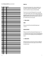
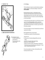
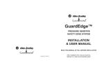
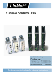
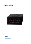
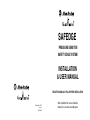
R SAFEDGE PRESSURE SENSITIVE SAFETY EDGE SYSTEM INSTALLATION & USER MANUAL READ THIS MANUAL IN FULL BEFORE INSTALLATION R Drawing No: 31611 Issue 2 EO: 26630 After installation this manual should be retained in a safe and accessible place Record of Thorough Inspection And Test (see section 6.2.2 and 6.2.3) Guardmaster Safedge Pressure sensitive safety edge system Installation and user manual Date SECTION 1 STORAGE AND HANDLING SECTION 2 SYSTEM DESCRIPTION SECTION 3 INSTALLATION & SPECIFICATIONS SECTION 4 ELECTRICAL CONNECTIONS SECTION 5 COMMISSIONING & USE SECTION 6 MAINTENANCE & SERVICE Inspected By Comments SAFEDGE PRESSURE SENSITIVE EDGE SYSTEM CONTROL UNIT Pt. No. 440F-C251P A1 STOP OPEN RUN A1 + Z2 MC 13 23 31 + Z2 MC 13 23 31 440F-C251D Safedge Pressure Sensitive Safety Edge System Control Unit Supply Voltage 230/110VAC (see selector) 50-60Hz 0r 24V AC/DC IP65 Hoseproof, Dust tight Safety Contacts 250V 2A N/O Aux Contacts 250V 2A N/C Safedge Profile Voltage 12Vdc EN 954-1 Category 3, prEN 1760-2 System response time 13mS See user manual for further information ISOLATE POWER BEFORE OPENING R STOP SAFEDGE Control unit EN 954-1 Cat. 3 pr EN 1760-2 OPEN RUN Isolate before opening R (A1/A2) 110/230VAC selectable (+/-) 24V AC/DC Made in the UK A2 A2 -- Z1 MC 14 24 32 -- Z1 MC 14 24 32 MADE IN THE UK SURFACE MOUNTING 1 DIN RAIL MOUNTING 26 Record of Routine Inspection And Test (see section 6.2.2 and 6.2.3) INTRODUCTION Date The Safedge sensitive edge sensing system is ideal as a safety sensor in applications such as power operated doors, automated vehicles and moving machinery beds etc. It can provide a continuous line of high sensitivity touch sensing along or around practically anything. Inspected By Comments This manual covers the use of the parts of the Safedge system. If joints or corners are required, contact your supplier. All installation work must be carried out by suitably trained and qualified personnel and should be in accordance with statutory requirements for safety. READ THIS MANUAL IN FULL BEFORE INSTALLATION. After installation this manual should be retained in a safe and accessible place. For any further assistance, please contact your supplier. 1.0 STORAGE & HANDLING STORAGE The Safedge control unit and Profiles should be stored within the temperature range of - 10°C to + 55°C. HANDLING AND TRANSPORT The Safedge control unit and Profile should be transported within the temperature range of - 10°C to + 55°C and should not be subjected to any impact or heavy loads. The original packaging should be used to give protection from excessive flexing. Always unpack carefully and avoid damage by the use of knives etc. 2.0 SYSTEM DESCRIPTION The Safedge system comprises of up to 50 metres of Profile, cable connector, a terminating resistor, “C” rail and a control unit. The control unit can monitor lengths of up to 50 metres. All Profiles have the same principle of operation. 25 2 Record of Routine Inspection And Test (see section 6.2.2 and 6.2.3) SAFEDGE PROFILES fig. 4 28 - 30 68 Comments 2 24.5 36 14 43 fig. 6 440F-E0310S Cushion factor 41mm 440F-E0510S Cushion factor 5mm with sealing lip 36 30 68 43 Inspected By 28.5 Cushion factor 19mm 440F-E1610S 440F-E1610N : Increased resistance to oil. 14 25 28.5 Date 2 Cushion factor 5mm 440F-E0110S 440F-E0110R : Red profile 440F-E0110N : Increased resistance to oil. fig. 5 30 fig. 3 9 12.5 28.5 25 fig. 2 9 12.5 24.5 fig. 1 29 17 FOR VARIOUS CONNECTION PIECES AND ACCESSORIES, PLEASE REFER TO OUR CATALOGUE 440F-E0804S Cushion factor 19mm with sealing lip 3 440F-E0210S Cushion factor 41mm with sealing lip. 24 Record of Routine Inspection And Test (see section 6.2.2 and 6.2.3) Date Inspected By Comments 10 25 10 25 10 25 "C" rail-aluminium C112/A 440F-R1212 Suitable for the fixing of all the Safedge Profiles. "C" rail-zinc coated steel C112/S 440F-R1112 Suitable for the fixing of all the Safedge Profiles. "C" rail PVC C112/PB = Black 440F-R1212PB C112/PR = Red 440F-R1212PR C112/PY = Yellow 440F-R1212PY Suitable for the fixing of all the Safedge Profiles. 3 colours available. "C" rail-aluminium C112/A3 440F-R1215 Ideal when external fixings of "C" rail is required. Accepts all profiles. 10 25 18 25 25 "C" rail-aluminium C112/A4 440F-R1216 Deeper rail allows cables to be run through channel under safedge profile. Accepts all profiles. "C" rail-aluminium C112/A2 440F-R1214 Ideal when external fixings of "C" rail is required. Accepts all profiles. 10 30 25 ALL “C” RAILS ARE SUPPLIED WITHOUT FIXING HOLES “C” Rail 440F-R1212 can be supplied curved to meet most applications 23 4 Each Profile uses a combination of non-conductive rubber and a flexible wire cored conductive rubber, bonded together to form a variety of energy absorbing Profiles. The Profile has no rigid internal parts which can “break through” or cause fatigue failures after prolonged use. The maximum operating voltage of the Profile is 12 VDC so no dangerous voltage is exposed if the Profile is accidentally cut or sheared. The copper wire core throughout the length of the Profile ensures that there is no significant build up of resistance over long lengths. Conductive Rubber Flexible Wire Cores Non Conductive Rubber 'Contact' Zone Record of Routine Inspection And Test (see section 6.2.2 and 6.2.3) Date Inspected By Comments 90° 45° 45° Flexible copper cores send the signal to the Evaluator The circuit through the Profile is monitored by the Safedge control unit which, when a 6KΩ resistance is present (i.e. normal run conditions), produces a signal to the machine control circuit. When the Profile is pressed, from any direction through 90° as shown above, the top conductive rubber strip compresses and touches the middle conductive rubber so creating a “short circuit” and the overall resistance drops. This is monitored by the control unit which initiates the machine shutdown. Any single fault in the Profile or the wiring connections to the Profile will be detected and the control unit outputs will go to a safe (OFF) state. Individual Profiles connect to each other by wires, axial connectors or standard 90° connectors. The Profiles are connected to the control units by two wires. The control unit has fully cross monitored safety relays and it is possible to configure the unit so that an external contactor fault will be detected. Compliance with the requirements of EN 954-1 Category 3 and pr EN 1760-2 is achieved for the control unit regarding electrical faults and can be met for the associated part of the machine control system. Compliance with the requirements of EN 954-1 Category 1 is achieved for the Profile. The Safedge system complies with the requirements of the European EMC Directive. Normal operation under interference conditions likely in industrial environments is assured as it has been tested and certified. NOTE:- Special measures may be required in the presence of abnormally high levels of EMI e.g. near to welding or induction heating equipment or near to radio transmitters / transceivers. 5 22 6.2.4 Repair 3.0 INSTALLATION OF THE SAFEDGE SYSTEM Prior to working on a Safedge system or machine control system, isolate the power source to the machine and Safedge system. Observe electrical safety precautions. ONLY USE 440F-A0020 CYANOACRYLATE. The cyanoacrylate adhesive ensuring a lasting sealing and high protection to IP65. User repairs are limited to replacement with new Safedge system parts. In the event of any problems, the units should be returned to the supplier. 3.1 INSTALLATION OF “C” RAIL Any repairs to the connecting wires should be made using heat shrink butt splice connectors. "C" RAIL After replacing any parts the inspection and test shown at 6.2.2 & 6.2.3, must be carried out with special attention given to those parts replaced. TAMPERING WITH COMPONENT PARTS WILL INVALIDATE WARRANTY. WARRANTY INVALID IF QUALITY SEAL IS BROKEN ON THE DIN RAIL (440F-C251D) CONTROL UNIT WARNING After maintenance or repair operations it is important that all fastenings, cable protection etc, are correctly refitted. Failure to do this or the use of non approved parts may result in the Safedge system failing to achieve its specified performance. CABLE CONNECTOR CONNECTOR WITH RESISTOR CLOSING CAP 21 TO CONTROL UNIT OR NEXT PIECE OF PROFILE 6 3.1.1 MOUNTING THE “C” RAIL 6.2.1 Profile Cleaning The Profiles should be kept clean of deposits such as swarf and other materials to prevent damage or dead-zones. It is permissible to use warm water and a mild detergent to clean the surface area. DO NOT USE SOLVENTS. Holes drilled on installation (Fasteners not supplied) 6.2.2 Routine maintenance inspection and test - (recommended weekly or after repair) Stop the machine, clean the Profile(s) and allow to dry off. Inspect the surface of the Profile for damage. Any damage that punctures the profile could let material or liquid in. It must be dealt with immediately. Check that all end caps, corners and joints are secure and free from damage. Damaged parts must be replaced immediately. Test the Profile operation. Two people may be required, one to press the Profile and one to observe the operation of the control unit. On systems using Manual reset mode, the reset button must be continuously pressed. Check that the RUN “Green” LED is illuminated when the profile is not pressed and that the STOP “Red” LED is illuminated when it is. Start the machine, press the Profile and check that the machine stops immediately. If these checks reveal any problems, do not allow use of the machine until they are rectified. Record all inspections and tests in a written log. 3.2 ASSEMBLY & INSTALLATION OF THE SAFEDGE PROFILE 3.2.1 Cut the Safedge Profile to length. Profiles without coasting chamber should be cut with rubber shears. Profiles with coasting chamber should be cut with a fine tooth saw. 6.2.3 Thorough examination and test - (twice yearly or after repair) To be undertaken by a person competent in electrical and mechanical engineering. a) Carry out tests at 6.2.2 b) Isolate the power source to the machine and Safedge system. Observe electrical safety precautions. c) Inspect the Profile and components thoroughly for mechanical damage. d) Disconnect the wires to the Profile at terminals Z1-Z2. e) Connect the wires from the Profile to the input of an ohmmeter. One person should now press the Profile with one hand at every point on the strip. The resistance should measure 6K +/- 10% when the profile is not pressed and no greater than 1K when it is. If these checks reveal any problems, do not allow the use of the machine until they are rectified. Record the inspection and test in a written log. 7 20 6.0 MAINTENANCE AND SERVICE 6.1 FAULT FINDING GUIDE 12 Symptom Probable Cause Check “Yellow” LED Illuminates. Open circuit in profile or connecting wiring. No LED’s illuminate even if Profile is pressed. Supply failure. No LED’s illuminate unless Profile is pressed and then the stop “Red” LED illuminates. Failure to reset. Unit appears to work correctly but there is no output. Blown fuse. Damaged or incorrect wiring. Z1-Z2 Terminals are secure. Cable for breaks Profile for damage. Voltage selector switch is set correctly. Supply fuse. Supply voltage is present. If using contactor monitoring, check each contactor is functioning correctly. MC-MC terminals are secure. Link is in place or Reset button functions correctly. Output fuses. All wiring for damage. Fault on Safedge causing the Outputs to fail safe Incorrect external connections Movement on any internal relays. REPLACE CONTROLLER. All wiring to contactors for mistakes. Machine does not stop if Profile pressed. Run “Green” LED goes off. Machine does not stop if Profile pressed. Run “Green” LED stays on. 3.2.2 When using the closing cap 440F-A1302 with sealing lip, the profile base has to be cut back to a length of 12mm. The cut must be made carefully to ensure that the profile base is completely trimmed off, leaving a flush surface. 3.2.3 The shaded areas must be roughened with emery paper 3.2.4 The closing caps are moulded with 4 grommets, each with a rubber plug. When fitting a resistor, leave the plugs intact. When making a cable connection, select the required cable exit and remove the plug from the grommet with a hole punch. DO NOT ALLOW THE USE OF THE MACHINE REPLACE CONTROLLER. 3.2.5 Pull the connecting cable through the hole. 6.2 MAINTENANCE This section should be read in full before any maintenance work is attempted. Attention is drawn to regulations for planned preventative maintenance under E.U. Directive 89/655/EEC (Implemented in Great Britain as the Provision and Use of Work Equipment Regulations 1992). During maintenance operations, disconnect the machine’s prime mover before working on the Safedge system. Observe electrical safety precautions. 19 8 3.2.6 Prick each of the copper wires with one of the needles. Press the needle contacts of the connector in the direction shown: (wedge outwards), straight into the copper wires. 5.3 APPLICATIONS 110/230V AC SUPPLY SAFEDGE PROFILE 6K RESISTOR L K2 MOMENTARY PUSH BUTTON +ve Z1 Z2 13 23 31 STOP (A1) 3.2.7 CAUTION The narrow side (wedge) of the connector must show outwards. K1 START SAFEDGE PROFILE SAFEDGE CONTROL UNIT 6K RESISTOR L (A2) N +ve Z1 Z2 13 23 31 (A1) E -ve MC MC 14 24 32 SAFEDGE CONTROL UNIT 3.2.8 Fold back the sealing lip of the cap; a) Apply adhesive to shaded area of closing cap as illustrated then affix to edge of profile, applying pressure for 10 seconds to ensure adhesion. b) Apply adhesive to remainder of shaded area and allow sealing lip to make contact with profile. IMPORTANT: Spread the adhesive evenly over the shaded area! Do not allow adhesive to enter inside the profile. EXTERNAL FUSE (A2) K1 N E -ve MC MC 14 24 32 EXTERNAL FUSE 110/230V AC Application with 1 contactor. (Shown with profile pressed). K1 K1 K2 K2 110/230V AC Application with 2 contactors, contactor monitoring and START/STOP circuit. (Shown with profile pressed) 9 Brown Z1 White Z2 + 18 3.2.9 To ensure complete seal apply more adhesive on the Safedge Profile around grommet/cable exit and sealing lip of the closing cap. 5.2 AUTOMATIC RESET MODE 1) Turn the power on a) Run “Green” LED illuminates. b) Safety contacts close. c) Auxiliary contacts open. d) Contactors energise. 2) Press the Profile a) Run “Green” LED extinguishes. b) Stop “Red” LED illuminates. c) Safety contacts open. d) Auxiliary contacts close. e) Contactors de-energise. 3) Release the Profile a) System has returned to step 1a. Terminal block tightening torque rating 7 in/lbs, suitable for wire sizes 16AWG. Use 16AWG minimum. Use Copper Conductors Only. Temperature rating of field wiring shall not be less than ambient. 3.2.10 Axial profile connector 440F-A0061S is used for extensions and repairs (see steps 1, 2, 3, 6 and 7) for the 440F-E0110 series of profiles only. For other types, use straight pin connectors. 440F-A0061S Comparative properties Profiles 440F-E0110N 440F-E1610N Tensile strength (reinforced) MPa Resilience (20°C) Low temperature flexibility Resistance to sunlight Resistance to heat ageing Resistance to oxidation Resistance to ozone Resistance to H2O Resistance to dilute acids Resistance to concentrated acids Resistance to oils & greases 26 F F G G F F G F F G Profiles 440F-E0110R 440F-E0804S 440F-E0210S 440F-E0510S 440F-E0310S G = Good F = Fair 3.3 CONTROL UNIT 3.3.1 TECHNICAL SPECIFICATION 440F-C251P Surface mount Conformity: Power Supply - user select: System response time: Environmental protection: 20 G G G G G G G G G P Key:- 17 440F-E0110S 440F-E1610S P = Poor Max. Safedge profile voltage: Nominal operating voltage: Max. output fuse: Impulse withstand voltage: Over voltage: Contamination level: Min. switched current/voltage: Power consumption: 440F-C251D DIN rail prEN 1760-2, EN 954-1: CATEGORY 3 110/230V AC (50-60Hz) and 24V AC/DC +10% -15% 13mS IP65. Enclosure IP40 DIN0470 Terminals IP20 DIN0470 12V DC (open circuit). 4V (run condition). 2A quick acting 5A quick acting 2500V. Category 2 III 10mA/10V <6 VA 10 440F-C251P Surface mount Relay outputs: Utilisation category: Safety inputs: Indication LED 1: LED 2: LED 3: Internal controls: Internal fuses: Max. output fuse: Ambient temp. range - control unit Ambient temp. range - profile Humidity: Vibration: MC-MC contactor monitor loop: Max. conductor size: Terminals: Installation group: Material: Fixing details: Housing: Weight: Miscellaneous: 11 440F-C251D DIN rail 2 x independant volt free N/O safety contacts 1 x volt free N/C auxiliary contact NOTE: Auxiliary should not be used for safety AC - 15; 2A / 250V DC DC - 13; 2A / 30V DC Safedge profile (open resistance 6KΩ) Green: Run. Yellow: Open. Red: Stop. AC voltage selector 2A safety fuses replaceable (2 off) 500mAT supply fuse replaceable (1 off) 500mAT supply fuse replaceable (1 off) N/A 4A on AC / 2A on DC -10°C to + 55°C. -5°C to +55°C excluding 110N & 01610N (0°C to 55°C) Up to 90% RH at + 55°C. Tested in accordance with IEC 68-2-6, frequency range 10 - 55Hz, displacement 0.15mm 10 cycles per axis, sweep rate, 1 octave per minute N/C (normally closed) contactor loop 1 x 1 mm2 stranded with sleeves stripped 1x2.5 mm2 stranded with sleeves stripped 5mm, 1 x 1.5mm2 solid conductor. 8mm, 1 x 4 mm2 solid conductor Minus terminal screws Plus-minus terminal screws M3.5 with M2 spring action. self lifting connection, washer terminal boards separately removable. C in accordance with VDE 0110. Polycarbonate 4 x M4 holes 35 mm DIN Rail D=75mm, H=130mm, W=130mm D=120mm, H=73mm, W=45.5mm, 16 way 650g 450g The Safedge Profile must be terminated with a 6KΩ resistor. 5.0 COMMISSIONING & USE SEQUENCE OF OPERATION When the unit is installed, check the following sequence of operation. 5.1 Manual reset mode. 1) Turn the Power on a) No LED’s illuminate. 2) Press the reset switch a) Run “Green” LED illuminates. b) Safety contacts close. c) Auxiliary contacts open. d) Contactors energise. 3) Press the Profile a) Run “Green” LED extinguishes. b) Stop “Red” LED illuminates. c) Safety contacts open. d) Auxiliary contacts close. e) Contactors de-energise. 4) Release the Profile a) Stop “Red” LED extinguishes. b) System has returned to step 1a. 5) If Profile is pressed before reset a) Stop “Red” LED will illuminate each time the Profile is pressed but the safety contacts will not energise. 16 4.6 Reset terminal MC-MC These terminals are used for a number of different functions (surface mount supplied jumpered, DIN rail supplied without jumper). Without the jumper the terminals can be connected to positively guided normally closed auxiliary contacts on the machine contactors to provide monitoring of the contactors in dual channel control systems. If one contactor fails to isolate the power at de-energisation of its control coil, the Safedge system will not allow the other contactor to be energised until the fault has been rectified. Fit a jumper between these terminals on the DIN rail unit if this function is not required.This terminal is also used for auto/manual reset. If the MC-MC terminal is left jumpered or connected up to the contactors normally closed contact only, the unit is in automatic reset mode. In automatic reset mode the output is achieved solely by removal of the actuating force. The out put is also achieved at power up of the actuator (when there is no actuation force present). If a spontaneous restart may generate a risk, based on the result of a risk assessment to EN1050, then this mode must not be used. See EN 60204 Pt.1 and EN954 Pt.1. For manual reset mode a normally open spring return (not latching) push button must be connected across the MC-MC terminals or in series with the contactors normally closed. When the actuating force is removed, the unit will not operate until the button is pressed. The button will also have to be pressed after power up of the control unit. actuating distance: response distance: 6.4mm 1.2mm 6.6mm 1.9mm 8.0mm 27.2mm 9.4mm 5.0mm • max. speed: 100 mm/s • suitable for the detection of fingers The control unit must not be mounted inside the hazard zone. Access to the control unit is required for manual reset or for routine indicator observation so it must be able to be seen operating. The control unit can be mounted on either side of power doors, as long as the only hazard is the actual doors. In all other cases the control unit can be mounted anywhere convenient outside the hazard zone, taking into account the access requirements for test and maintenance. 3.3.2 MOUNTING 130mm 115mm 75mm Pg16/21 115mm Pg16/21 4 x M4 Fixing Holes 440F-C251P (Surface Mounted) Connection in Parallel & Series CONNECTING IN SERIES If more than one profile is to be used they are normally connected in series as shown. 7.8mm 8.4mm 130mm 4.7 Profile connection to control units These terminals are used to connect the Profile to the:Z1 = Brown (inner conductor). Z2 = White (outer connector). Refer to 5.3 APPLICATIONS. NOTE: Profile must be terminated with a 6KΩ Resistor (yellow) for series connection. When two profiles are connected directly to Z1 and Z2 (parallel) then each profile should be terminated with a 15K resistor (blue). 440F-E0110N 440F-E0110S 440F-E0310S 440F-E1610N 440F-E1610S 120 45.5 ALTERNATIVE CONNECTION METHOD A1 + Z2 MC 13 23 31 A2 -- Z1 MC 14 24 32 CONNECTING IN PARALLEL Uses 15K resistor (blue) Uses 6K8 resistor (yellow) 73 A maximum of two profiles can be connected in parallel to assist in ease of wiring in certain applications. 35MM DIN RAIL MOUNTING 440F-C251D (Din Rail Mounted) 15 12 4.0 ELECTRICAL CONNECTIONS - Safedge control unit 4.7 STOP OPEN RED YELLOW CONTROL UNIT INSTALLATION AND WIRING - (Follow steps 4.1 to 4.7 for correct installation) 4.6 IMPORTANT: Wiring must be in accordance with the National Electric Code and applicable local codes and ordinances RUN GREEN 4.1 Mains selector switch If using a 110V AC or a 230V AC supply, the voltage selector switch should be set as appropriate before turning the power on. The unit is set to 230V AC when manufactured. LED INDICATION Z1 Z2 MC MC 4.2 Mains input terminal LN (A1, A2, ) If a 110V AC or 230V AC supply is used it should be wired, together with a protective earth (ground) to the terminals shown. The size of the protective earth (ground) wire should be at least equal to that of the supply wire. Also check (4.1). If these terminals are used, ignore (4.3). 110V 4.1 230V 4.3 24V AC/DC input terminal +ve and -ve If a 24V AC/DC supply is being used, the supply should be connected to these terminals, ensuring that the correct polarity is observed. Do not make any connections to the terminals of (4.2). Where a 24V AC or DC supply is used, it must be isolated from the mains supply in accordance with international electrical safety pratice (IEC 364-4-41). One pole should be earthed. For 24V DC the negative pole should be earthed (grounded). With 24V AC the earthed (grounded) pole of the power supply should be connected to the -ve terminal. + -ve ve 31 32 13 14 23 24 L N SUPPLY FUSE 500mA SAFETY FUSES 2A 4.2 4.3 4.4 4.5 440F-C251P (Surface Mounted) A1 SUPPLY FUSE 500mA 4.4 Aux Output terminal 31 and 32 This terminal provides an auxiliary normally closed contact (i.e. closed when the green “Run” light is off) which is suitable for indication or for alarm devices. As this is an auxiliary, it must not be connected to the safety circuit. + Z2 MC 13 23 31 STOP (RED) OPEN (YELLOW) RUN (GREEN) 110V 4.2 4.1 4.3 4.5 4.7 4.6 4.4 230V A2 4.5 Safety Output terminal 13, 14, 23 and 24 These are volt free contacts for connection to the machine safety circuits i.e, they are connected in series with the machine contactor control circuit. (Max. rating 2A at 250V AC). Both of these safety circuits are internally fused but must also be externally protected with a 2A quick acting fuse. If one contactor is being used, terminals 13 and 24 are required and terminals 14 and 23 should be jumpered together. For 2 contactors with 2 independent control circuits (i.e. a dual channel system), use 13-14 for one contactor and 23-24 for the other. For 2 contactors, also see (5.3). -- Z1 MC 14 24 32 440F-C251D (Din Rail Mounted) 13 14