1
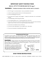
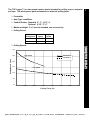
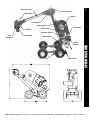
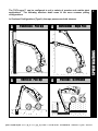
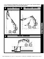
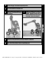
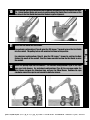
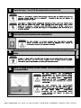
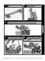
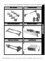
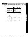
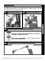
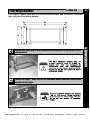
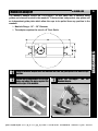
OPERATING INSTRUCTION MANUAL TUF-Lugger ™ [email protected] | 13309 Beach Ave. Marina del Rey, CA 90292 | Phone: 800-WCT-PROD (800-928-7763) | Fax: 310-306-9343 IMPORTANT SAFETY INSTRUCTIONS READ ALL INSTRUCTIONS BEFORE USING THE TUF-Lugger™ WARNING: TO REDUCE THE RISK OF FIRE, ELECTRIC SHOCK, OR INJURY: a The TUF-Lugger™ is an electrical device. Use only as described in this manual. a Connect to a properly grounded outlet only. See Grounding Instructions. a Do not use with damaged cord or plug. a Do not leave the TUF-Lugger™ when plugged in. Unplug from outlet when not in use and before servicing. a Do not handle plug or Power Pack with wet hands. a Do not unplug by pulling on cord. To unplug, grasp the plug, not the cord. a Do not pull or carry by cord, use cord as a handle, close a door on cord, or pull cord around sharp edges or corners. Do not run over cord. Keep cord away from heated surfaces. a Do not remove or modify the 15 Amp, 125 VAC plug. a Do not use in wet or damp locations. Do not expose to rain. Store indoors. a Do not use in the presence of flammable liquids or gases. GROUNDING INSTRUCTIONS This appliance must be grounded. If it should malfunction or breakdown, grounding provides a path of least resistance for electric current to reduce the risk of electric shock. This appliance is equipped with a cord having an equipment-grounding conductor and grounding plug. The plug must be inserted into an appropriate outlet that is properly installed and grounded in accordance with all local codes and ordinances. WARNING - Improper connection of the equipment-grounding conductor can result in a risk of electric shock. Check with a qualified electrician or service person if you are in doubt as to whether the outlet is properly grounded. Do not modify the plug provided with the appliance - if it will not fit the outlet, have a proper outlet installed by a qualified electrician. This appliance is for use on a nominal 120-volt circuit and has a grounding attachment plug that looks like the plug illustrated in the adjacent sketch. Make sure that the appliance is connected to an outlet having the same configuration as the plug. No adaptor should be used with this appliance. SAVE THESE INSTRUCTIONS [email protected] | 13309 Beach Ave. Marina del Rey, CA 90292 | Phone: 800-WCT-PROD (800-928-7763) | Fax: 310-306-9343 1 OPERATION 5 TRANSPORT 9 ACCESSORIES 10 11 12 13 14 15 18 Duct Guides Extension Arms Floor Mount Adapter Manhole Adapter Universal Adapter Load Monitor TABLE OF CONTENTS SPECIFICATIONS [email protected] | 13309 Beach Ave. Marina del Rey, CA 90292 | Phone: 800-WCT-PROD (800-928-7763) | Fax: 310-306-9343 The TUF-Lugger™ is a two-speed capstan winch intended for pulling rope or polyester pull tape. The winch power pack is mounted in a wheeled, pulling frame. 1 ¾ Footswitch ¾ Amp Type Load Meter ¾ Conduit Guides: Standard 2”, 3”, 3-1/2”, 4” Optional 2-1/2”, 5”, 6” ¾ Maximum Height: 6’-6” (can be extended, see accessories) ¾ Pulling Forces: Maximum Pulling Force Continuous Low Speed 4,000 lb High Speed 2,000 lb Intermittent 6,500 lb 3,250 lb SPECIFICATIONS ¾ Pulling Speeds: 30.0 25.0 Continuous High Speed Pulling Speed (fpm) Intermittent 20.0 15.0 Low Speed 10.0 5.0 0.0 0 1000 2000 3000 4000 5000 6000 7000 Pulling Force (lb) [email protected] | 13309 Beach Ave. Marina del Rey, CA 90292 | Phone: 800-WCT-PROD (800-928-7763) | Fax: 310-306-9343 2 Extension Arms Elbow Sheave Wrist Sheave Capstan Locking Pin Mounting Pin Wrist Pin Power Pack Load Meter Deflector Sheave Duct Guide Mounting Pin Speed Selector Boom Pin Base Plate SPECIFICATIONS Duct Guide Pin [email protected] | 13309 Beach Ave. Marina del Rey, CA 90292 | Phone: 800-WCT-PROD (800-928-7763) | Fax: 310-306-9343 The TUF-Lugger™ can be configured to suit a variety of premise and outside plant applications. The following sketches detail some of the more common pulling configurations. 3 In Overhand Configurations (Type A), the rope passes over both sheaves. Panel Box - Pull Up A Horizontal – High Pull A Vertical - Pull Up A Pull Box - Overhand SPECIFICATIONS A [email protected] | 13309 Beach Ave. Marina del Rey, CA 90292 | Phone: 800-WCT-PROD (800-928-7763) | Fax: 310-306-9343 In the Underhand Configurations (Type B), the rope passes under the Wrist Sheave, between the Extension Arms, and over the Elbow Sheave. Horizontal – Low Pull SPECIFICATIONS B Panel Box - Pull Down B 4 B Pull Box - Underhand [email protected] | 13309 Beach Ave. Marina del Rey, CA 90292 | Phone: 800-WCT-PROD (800-928-7763) | Fax: 310-306-9343 1 5 Review the jobsite safety requirements. Follow Standard procedures when accessing vaults and manholes, including gas detection, ventilation, and work area protection. Failure to do so may result in death or serious injury. Use extreme caution when working around live electrical circuits. Failure to do so may result in death or serious injury. Wear recognized safety equipment including hardhat, safety glasses, safety shoes, and leather work gloves. Failure to do so may result in personal injury. Inspect the condition of the TUF-Lugger™, checking for worn or damaged parts. Have damaged parts replaced by an authorized service center. Any attempt to modify the TUF-Lugger or use other than replacement parts will void the warranty and may result in death or serious injury. Ensure that the protective cap for 120 VAC load monitor receptacle is installed when the receptacle is not in use. Failure to do so may result in death or serious injury. OPERATION 2 Periodically lubricate the drive chains with light machine oil. 3 Examine the condition of the pulling rope. Check for contamination with mud, sand, or dirt. Check for rust discoloration. Check for broken or worn strands. Use a pulling rope with a maximum rated capacity that meets or exceeds the TUF-Lugger maximum pulling force of 6,500 lb. Failure to do so may result in death or serious injury. Downgrade or discard pulling rope that has been subject to overload, or physical degradation. Failure to do so may result in death or serious injury. [email protected] | 13309 Beach Ave. Marina del Rey, CA 90292 | Phone: 800-WCT-PROD (800-928-7763) | Fax: 310-306-9343 4 Roll the TUF-Lugger™ into the desired operating location. 5 Uncoil the footswitch cord and power cord. 6 Grasp the spare Locking Pin and tilt the TUF-Lugger™ rearwards until it rests on the base plate. 8 Remove the existing Duct Guide by removing the Guide Pins and Wrist Pin. 9 Select a Duct Guide suitable for the size of conduit being used. Remove the Locking Pin and rotate the Extension Arm assembly to the desired position. Continue to rotate past the desired position until the next set of pin holes aligns. Replace the Locking Pin. OPERATION 7 6 [email protected] | 13309 Beach Ave. Marina del Rey, CA 90292 | Phone: 800-WCT-PROD (800-928-7763) | Fax: 310-306-9343 Orient the new Duct Guide depending on the pulling configuration and secure with the Wrist Pin. Rotate the Duct Guide and secure in position using Duct Guide Pins in whichever of the two holes in the Duct Guide that provides the best angular alignment. 11 Install the Duct Guide into the conduit. For overhand configurations (Type A), pivot the TUF-Lugger™ forward to insert the Duct Guide into the conduit. The pulling forces will maintain the frame in this position. For underhand configurations (Type B), pivot the TUF-Lugger™ forward to position the Duct Guide at the mouth of the conduit. Pivot the frame rearward to allow the Duct Guide to enter the conduit. 12 Install the pulling rope over the sheaves. For overhand configurations (Type A), the rope goes over both sheaves. For underhand configurations (Type B), the rope goes under the Wrist Sheave, between the Extension Arms, and over the Elbow Sheave. Continue the rope clockwise around the capstan and around the deflector sheave. 7 OPERATION 10 [email protected] | 13309 Beach Ave. Marina del Rey, CA 90292 | Phone: 800-WCT-PROD (800-928-7763) | Fax: 310-306-9343 12 8 Plug the TUF-Lugger™ into a 120 V, 15 A grounded outlet or extension cord. Read all electrical safety instructions located on the first page of this manual before using the TUF-Lugger. Failure to do say may result in serious injury or death. Use only a three prong grounded extension cord with the proper wire size for the length of cord. For lengths less than 50ft, use a 14Ga cord as a minimum. Lengths from 50-100ft, use a 12 Ga cord as a minimum. Failure to do so may result in overheating and damage to the electric motor. Select the pulling speed depending on the anticipated load. Do not attempt to change speeds with the motor running. Speed changes while the motor is running may result in permanent damage to the TUF-Lugger. 14 Manually apply tension to the tail end of the rope and depress the footswitch to begin pulling. Stand at least 30° to either side of the pulling rope while under load. The pulling rope may fail under tension and release stored energy. Failure to do so may result in death or serious injury. 15 OPERATION 13 Monitor the pulling load using the meter provided. Use the low speed mode if the pulling force exceeds 2000 lb. Do not operate the TUF-Lugger continuously at pulling forces above 2,000 lb in high speed mode or 4,000 lb in low speed mode. Continuous operation of the TUF-Lugger above these ratings may overheat and damage the motor. Do not operate the TUF-Lugger intermittently at pulling forces above 3,250 lb in high speed mode or 6,500 lb in low speed mode. Intermittent operation of the TUF-Lugger above these ratings may result in death or serious injury. [email protected] | 13309 Beach Ave. Marina del Rey, CA 90292 | Phone: 800-WCT-PROD (800-928-7763) | Fax: 310-306-9343 1 Rotate the Duct Guide into the position shown. 3 Place the spare locking pin in the elbow plate. Place your foot on the front axle. Grasp the locking pin and pull forwards to pivot the TUF-Lugger™ into the transport position. 4 Wrap the footswitch cord and power cord around the cutouts in the base plate. Stow the footswitch on the frame. 9 Rotate the TUF-Lugger™ Extension Arms into the position shown. TRANSPORT 2 5 Steer the TUF-Lugger™ by pushing down on the spare locking pin, raising the rear wheels and rotating about the front wheels. [email protected] | 13309 Beach Ave. Marina del Rey, CA 90292 | Phone: 800-WCT-PROD (800-928-7763) | Fax: 310-306-9343 There are several accessories available for the TUF-Lugger™ to enhance its capabilities. Extension Arms Floor Mount Adapter Manhole Adapter Universal Adapter Load Monitor ACCESSORIES Duct Guides 10 [email protected] | 13309 Beach Ave. Marina del Rey, CA 90292 | Phone: 800-WCT-PROD (800-928-7763) | Fax: 310-306-9343 Duct Guides 11 # 40010-XXX The TUF-Lugger™ comes standard with Duct Guides to suit 2”, 3”, 3-1/2”, and 4” conduit. Guides are also available as optional accessories to suit 2-1/2”, 5”, and 6” conduit. Conduit Size 2” 2-1/2” 3” 3-1/2” 4” 5” 6” OD ID Std 1.91” 2.38” 2.88” 3.54” 3.93” 5.00” 6.00” 1.67” 2.07” 2.50” 3.11” 3.43” 4.50” 5.50” X Opt X X X X X X ACCESSORIES Part Number 40010-200 40010-250 40010-300 40010-350 40010-400 40010-500 40010-600 [email protected] | 13309 Beach Ave. Marina del Rey, CA 90292 | Phone: 800-WCT-PROD (800-928-7763) | Fax: 310-306-9343 Extension Arms 12 The range of the TUF-Lugger™ may be extended by replacing the standard Extension Arms with longer sections of 2” steel rigid conduit or 2” Sch40 steel pipe. This will allow higher box pulls and deeper vault pulls. Loosen the two bolts in the Outboard Arm Fitting and remove the Fitting. B3 Cut two identical lengths of 2” steel rigid conduit or 2” Sch40 steel pipe. B2 Loosen the two bolts in the Inboard Arm Fitting and remove the Extension Arms. Use only 2” steel rigid conduit or 2” Sch40 steel pipe. Failure to do so may result in death or serious injury. Do not exceed a maximum length of 14 feet. result in death or serious injury. B4 ACCESSORIES B1 Failure to do so may Re-assemble the new Extension Arms to the Inboard and Outboard Arm Fittings. [email protected] | 13309 Beach Ave. Marina del Rey, CA 90292 | Phone: 800-WCT-PROD (800-928-7763) | Fax: 310-306-9343 Floor Mount Adapter 13 # 40000-400 C1 Align the Floor Mount Adapter with the direction of pull and secure to the floor with 4 x 5/8” concrete inserts. Use only concrete inserts with an ultimate pullout force of 8,000 lb. ensure that they are installed in accordance with the instructions provided by the insert manufacturer. Failure to do so may result in death or serious injury. C2 ACCESSORIES TUF-Lugger™ Power Pack may be removed from the frame and secured to a concrete floor using the Floor Mount Adapter. Place the TUF-Lugger™ Power Pack into the Floor Mount Adapter and secure using the pins provided with the adapter. The TUF-Lugger Power Pack weighs 125 lb. Use proper lifting technique when moving the power pack. Failure to do so may result in personal injury. [email protected] | 13309 Beach Ave. Marina del Rey, CA 90292 | Phone: 800-WCT-PROD (800-928-7763) | Fax: 310-306-9343 Manhole Adapter 14 # 40000-300 The Manhole Adapter allows the TUF-Lugger™ to pull cable into a manhole using guides and sheaves located in the manhole. It features two independent stop plates and an independent guide plate which allow the rope to be pulled from any position in the manhole. ¾ Manhole Range: 18” – 36” Diameter D1 Place the manhole adapter over the manhole and slide the guide plate to the desired rope position. D2 Loosen the locking handles on the stop plates and adjust the plates against the inside edges of the manhole. D3 ACCESSORIES SWL 10,000 LB 40000-300 ¾ The adapter requires the use of a 6” Duct Guide. Install the TUF-Lugger™ into the Manhole Adapter. [email protected] | 13309 Beach Ave. Marina del Rey, CA 90292 | Phone: 800-WCT-PROD (800-928-7763) | Fax: 310-306-9343 Universal Adapter 15 # 40000-500 This problem can be overcome with the Universal Adapter. It is a second set of extension arms with a joint that can bend and rotate. It is installed between the standard Extension Arms and the Duct Guide. The Universal Adapter allows the TUFLugger™ frame to be set at an angle to the line of pull. ACCESSORIES For horizontal pulls, the TUF-Lugger™ must be positioned directly in line with the conduit. For some applications, this is not possible as the TUF-Lugger™ is physically restricted by a manhole, or sidewall. [email protected] | 13309 Beach Ave. Marina del Rey, CA 90292 | Phone: 800-WCT-PROD (800-928-7763) | Fax: 310-306-9343 E1 Adjust the angle of the extension arms on the TUF-Lugger™. For Overhand Pulls (Type A), the outboard end of the arms should be below the height of the conduit. For Underhand Pulls (Type B), the outboard end should be above the height of the conduit. E2 Install the Duct Guide onto the sheave end of the Universal Adapter. For Overhand Pulls (Type A), the slot in the plate should be up. For Underhand Pulls (Type B), the slot in the plate should be down. Overhand Pulls (Type A) 16 # 40000-500 ACCESSORIES Universal Adapter Underhand Pulls (Type B) [email protected] | 13309 Beach Ave. Marina del Rey, CA 90292 | Phone: 800-WCT-PROD (800-928-7763) | Fax: 310-306-9343 Universal Adapter 17 # 40000-500 E3 Insert the Duct Guide into the end of the conduit. Loosen the nut on the adjustment plate and rotate the Universal Adapter so that it will align with the Extension Arms. E4 Install the Universal Adapter onto the TUF-Lugger™ Extension Arms and secure in place using the Wrist Pin and Duct Guide Pins. Tighten the nut on the adjustment plate. E5 Install the pull rope. It may pass between the TUF-Lugger™ Extension Arms but must not pass between the Universal Adapter Arms. When correctly installed, the rope will run parallel to the Universal Adapter Arms. ACCESSORIES The added weight of the Universal Adapter will make the assembly unstable until all of the pins are installed. Exercise caution. Failure to do so may result in personal injury. Ensure that the rope does not pass between the arms of the universal adapter. Failure to do so may result in death or serious injury. [email protected] | 13309 Beach Ave. Marina del Rey, CA 90292 | Phone: 800-WCT-PROD (800-928-7763) | Fax: 310-306-9343 Load Monitor 18 # 40000-200 The Load Monitor system uses a load cell to measure the reaction force on the Power Pack and convert it to a line tension reading. It consists of a load cell, digital readout, and audible alarm. It receives its power from the TUF-Lugger™ via an auxiliary power cord. The Load Monitor can only be used with the TUF-Lugger™ frame. Load Cell ¾ Line Tension Range: 0 – 6500 lb ¾ Audible Alarms: 2000 lb / 4000 lb ¾ Alarm Override Switch Analog Output: 0 – 10 VDC Digital Display Alarm Switch Power Switch Aux Power Cord Installation of the Load Monitor requires a screwdriver and two 3/4” wrenches. Once installed, the Load Monitor can be left in place permanently. F1 Remove the front Mounting Pin and raise the Power Pack. Install the load cell into the frame cross member. Secure in place with nut and lock nut. Replace the Mounting Pin. F2 ACCESSORIES ¾ Remove the screws that secure the Load Monitor cover. Remove the cover and attach the Load Monitor to the top of the TUF-Lugger™ Power Pack using the screws provided. Replace the cover. [email protected] | 13309 Beach Ave. Marina del Rey, CA 90292 | Phone: 800-WCT-PROD (800-928-7763) | Fax: 310-306-9343 Load Monitor F3 19 # 40000-200 Unplug the TUF-Lugger™ Power Pack. Remove the protective cap on the auxiliary power receptacle. Connect the Load Monitor cord to the receptacle. F4 Install the Transport Knob into the Power Pack mounting bracket. Ensure that the Knob does not restrict the movement of the bracket against the load cell. F6 Secure the load cell wire to the underside of the TUF-Lugger™ frame by using the half clips and screws provided, screwing them into the pre-drilled holes. F5 Secure the load cell wire to the side of the TUF-Lugger™ frame by removing the three rear chain cover screws and reinserting them with the half clips provided and routing the wire as shown. ACCESSORIES Ensure that the TUF- Lugger Power Pack is unplugged before making this connection. Failure to do so may result in death or serious injury. [email protected] | 13309 Beach Ave. Marina del Rey, CA 90292 | Phone: 800-WCT-PROD (800-928-7763) | Fax: 310-306-9343 Load Monitor 20 # 40000-200 Operation of the Load Monitor is straightforward. F7 Set the Alarm Switch to the “ON” position. When the TUF-Lugger™ speed selector is set in the “LO” position, the 2000 lb alarm is automatically disabled. F8 Set the Power Switch to the “ON” position. The pulling line tension is displayed in pounds. F9 To secure the TUF-Lugger™ for transport, screw the Transport Knob clockwise until resistance is felt. This prevents vibration damage to the load cell. ACCESSORIES F6 Turn the Transport Knob counter-clockwise so that the Power Pack is free to apply load against the Load Cell through the front mounting bracket. [email protected] | 13309 Beach Ave. Marina del Rey, CA 90292 | Phone: 800-WCT-PROD (800-928-7763) | Fax: 310-306-9343