1
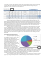
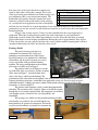
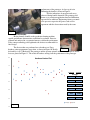
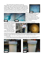
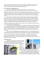
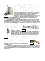
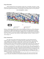
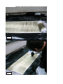
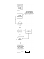
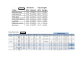
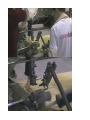
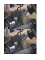
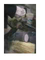
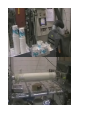
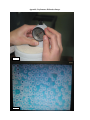
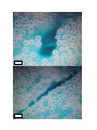
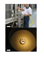
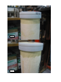
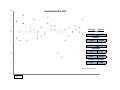
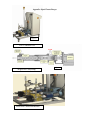
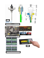
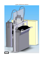
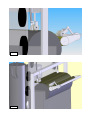
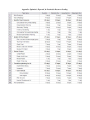
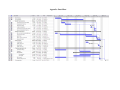
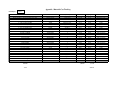
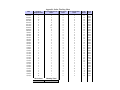
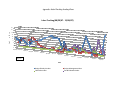
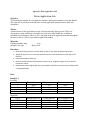
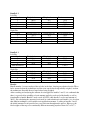
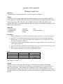
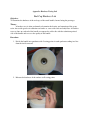
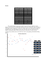
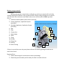
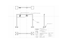
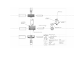
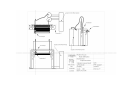
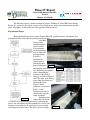
Phase IV Report
Dept of ME Senior Design 2007
Team 16
Sponsor: Air Liquide
Synopsis
The following report is a written statement of progress for Phase IV of the 2007 Senior Design
Project. It is intended to provide an overview of the design process that has been implemented up to this
point. All graphics are shown full size in the appendix of this document.
Experimental Design
Having finalized the proof of concept design in Phase III, specific laboratory experiments were
performed in order to fine-tune the prototype for final testing.
A modular
design, which
accepted multiple
types of rollers,
was constructed
for the preliminary
tests of rollers and
resin application.
In order to
determine the
specific type of
roller that would
be used during the
Figure 1
final machine trial, mock trials
Table 1
were held using all candidate
rollers, mimicking the
operation of the proof of
concept, as shown in Figures 1
and 2. The logic of the testing
process that was followed is
shown to the left in
Figure 3. Roller
parameters are shown in
Table 1. A full
laboratory procedure is
shown in the appendix
of this document.
Following trials
Figure 3
of the rollers, the results
of each trial were qualitatively analyzed by examining the
process, the end product, and then quantified in a survey. The
amount of resin applied to the testing sheets was measured
Figure 2
and compared for consistency. The survey rated resin depth,
resin coating, air pockets, fiber alignment, wicking, and waste through the opinions of factory engineering
personnel. The results of this analysis clearly favored a particular roller model designed for epoxy
application, as can be seen in the scores listed in Table 2.
Table 2
A thin nap length optimized infiltration in a clean manner without bubbles and fiber abuse. The
primary factors that characterized these rollers were amount of resin the nap can hold and the ability of the
roller to pressurize the fluid as it is pulled under. The most favorable roller parameters were found in the
Wooster R232 4in Epoxy Glide. Not only were the desired properties found, but new properties specific for
holding and releasing resin were incorporated in the construction of this roller. The four inch roller was
chosen to fulfill the desired resin application band.
During the final proof of concept testing, new components for the implementation were found
necessary. Although these reiterated previously stated requirements of proper roller contact, further
details about implementation were discovered during the final test. It was realized a range of pressure
optimizes both resin infiltration and minimal fiber disturbance. For future implementation, the previous
design component of a spring load initial application will be reintroduced in the final design. Also, the
primary roller needs to be fixed more rigidly, because small deflection alters the initially prescribed
bandwidth.
Updated Performance Requirements
Several performance requirements
were updated to ensure the success of the
design. The new requirements were
established during the preliminary testing
of the rollers. Various concerns and
corresponding modifications were
identified and implemented on the final
proof of concept. The updated wants from
Figure 4 were then rescored and
translated to new target values that are
displayed in Table 2 (next page). The two
Figure 4
primary metrics concerning technician
interaction and void content remained unchanged as the proof of concept evolved.
The behavior of the rollers was translated into a metric. Initial tests were performed on rollers
that contained bristles and were similar to the paint brushes that are currently used. After testing, the
misalignment of fibers, air bubbles, and incomplete infiltration were identified as prominent issues.
Variations of smooth rollers were found to produce the best results.
A new performance metric added is a quantified flow rate. Testing began by pouring resin from
paper cups, and approximating the flow rate then measuring the amount of resin used. It was found
that some areas of the loom sheet had too much resin
Table 2
Updated Target Values
applied, while others did not have enough. This lead to
1
No significant voids
some areas having great infiltration and others having very
2
One technician to oversee
poor infiltration, thus a very inconsistent method. The
3
No break of roller contact
bandwidth varied greatly along the length of the loom,
4
200-230 g/min flow rate
which was reflected in the inconsistency of the wicking.
5
Resin at 40 degrees C
As a result initial resin application in terms of bandwidth
and flow rate was found to be of great importance. It was determined that part of the problem in
pouring the resin was due to resin viscosity which was found to be closely tied to the resin temperature
during application.
A target value of forty degrees Celsius was then established for the resin temperature at
application. When the team began testing with resin at this temperature it was found that the
application was made much easier. More importantly the viscous effects that had been preventing
proper infiltration were now helping in infiltration. Heating the resin to approximately forty degrees
Celsius lowered the viscosity and provided not only a more reliable method of pouring the resin but a
smoother infiltration by the roller onto the fiber sheet as well.
Prototype Details
The proof of concept prototype was
constructed to demonstrate key design, and
technology recommendations for a final design.
Specific parameters were optimized in a laboratory
environment, and the proof of concept was used to
create a test bundle on the production forming
machine. The testing configuration for the machine
trial can be seen fully set up in Figure 5.
The primary roller seen in Figure 6 coats the
top of the fiber sheet as it advances, and the secondary
roller, shown in Figure 7, coats the bottom of the
Figure 5
sheet as the sheet is rolled onto the bushing. The
performance of this subsystem was the primary focus of the proof of concept demonstration. Given
logistics and budget constraints, a makeshift resin application system was devised to apply resin in a
controllable manner. Caulking guns where outfitted with custom cartridges to deliver resin in 50g
increments, as shown in Figure 8.
The primary roller maintains a fixed position throughout bundle
formation. The secondary roller’s height is adjusts as the bundle expands
through the use of a simple rotational joint. All components are modified
store-bought systems, selected for low cost, disposability, and
adaptability.
Figure 6
The prototype was outfitted on the production forming machine,
and a bundle was produced. One end of the bundle was
hand painted by an operator for comparison. The bundle
was then cured, machined, and analyzed to determine the
Figure 8
Figure 7
performance of the prototype. A close-up of resin
infiltrating the bundle is shown in Figure 9.
The first indications of superior results were
observed during bundle formation. The prototype laid
down a very consistent application band and infiltration
appeared to be sufficient. Engineering factory personnel
were present to supervise the process and were in
agreement with the observations made by the team.
Figure 9
Performance Evaluation
Having formed a bundle on the production forming machine,
specific performance characteristics could then be evaluated. Data was
gathered and analyzed in a systematic format to validate the performance
of the concept technology and legitimatize the choices recommended for
final design.
The first test that was performed was a hardness test. Forty
Figure 10
hardness point measurements were taken, as shown in Figure 10. Ideally
the hardness is 65-75 Rockwell. The prototype and the operator-painted end were then compared and the
data was plotted in Figure 11. The results of hardness testing favor the performance of the prototype.
80
Hardness Scatter Plot
75
Prototype
65
60
55
Prototype
Figure 11
50
Operator
Average
70.75
70.05
Median
70.50
70.00
Minimum
66
58
Maximum
76
78
Variance
6.51
25.00
Standard Deviation
2.55
5.00
70
Operator
The second test that was performed was microscopy
characterization. In order to compare the performance, both ends were
examined. The surfaces of the end-caps were analyzed at 100x using an
optical magnifier. The inner diameter of the fibers is 90µm and the outer
diameter is 160µm. Ideally no voids should exist, and the surface should
show uniform distribution as can be seen in Figure 11. Small voids are
acceptable, as they do not necessarily constitute a full leak. However, as
Figure 12
the size of the void increases, the chance of a gas leak is greatly raised.
The end formed by the prototype
possessed fewer voids, with less severity
than the end painted by the operator
despite his experience and skill.
Moreover, less interface voids occur
between layers on the prototype end, due
to the constant applied pressure from the
rollers. Typical voids are shown in
Figure 13
Figure 14
Figures 13 and 14.
The third test that was performed was a gas leak check. The bundle was pressurized to
approximately 8 psi and glass beads were placed on the surface of the end caps, as shown Figure 15. Any
leaks in the bundle would cause
the glass beads to displace,
showing a distinct motion on the
end-cap. As shown in Figure 16
no leaks were detected on the
end formed by the prototype.
Given the very positive
results of the bundle, the sponsor
Figure 15
Figure 16
decided to post-treat the bundle
and perform post-production testing. From this testing further void mapping, wicking characterization, and
nitrogen recovery rate information will be obtained. This bundle has been post-treated, and the data from all
tests will be available to the sponsor in approximately one week. A final leak check also yielded
satisfactory results.
In order obtain a basic idea of the wicking experienced by the bundle, the resin band was examined
for both end-caps. The end formed with the prototype showed a much more consistent band than the
Figure 17
Figure 18
operator painted end. Both end-caps are shown to the left, prototype end in Figure 17, operator end in
Figure 18. This provides a general idea of the extent of internal wicking. Internal wicking will be
determined following post-production testing and bundle dissection.
Proof-of-Concept & Solution Differences
There are several differences between the proposed proof of concept and the final
recommended implementation design. One of the major differences between the two is the use of
Liquid Controls systems to provide consistent resin application. This application system will provide a
designated constant flow rate. The constant flow rate will add a much greater degree of consistency by
applying the optimal amount of resin in an automated manner. Because of this factor, undesirable
wicking and resin voids will be decreased. Moreover, less resin will be wasted in the manufacturing
process.
The temperature of the resin will be continually regulated in the final implementation plan,
unlike the proof of concept. While testing the prototype, the resin was heated to approximately 40
degree Celsius before it was loaded to the resin gun and applied. The heating of the resin enabled a
better viscosity, but the temperature slowly dropped below the 40 degrees as the resin was applied to
the fibers. The implementation plan provides heating of the resin lines until the exact moment of
application, through the tube and nozzle tip. This will eliminate any cooling before application,
providing a regulated temperature 40 degrees Celsius. This creates a favorable resin viscosity, aiding
effective fiber infiltration during production.
A permanent setup at the forming machine is incorporated in the final implementation proposal.
Instead of employing temporary boom stands next to the machine, a fixed frame will be permanently
located, bolted or welded in place in a stable position. This will ensure steady application and eliminate
variance in the application area and initial bandwidth. Moreover, the frame will provide a greater
degree of rigidity, providing precise positioning of components without concern of shifting during
operation.
The cost of the final implementation is much greater than the cost of the proof of concept. The
working budget of the project is $1500, while the final implemented system is $112,000. The prototype
was chosen in accordance with the approved concept budget as a technology demonstrator. Having
proven the concept fundamentals, a production solution may be constructed using applicators
purchased from Liquid Controls. The system from Liquid Controls will provide more reliability,
temperature control, and flow rate control than the application system design to showcase the concept
technology of the proof of concept.
Design Integration
The final proposed design is a synthesis of the roller
technology that was validated in the proof of concept and the
trusted technology of Liquid Controls resin dispensary
systems. The final design addresses the issues discovered in
the proof of
concept and
provides a
Figure 19
reliable solution
for production. A full operations manual, including design
drawings, is located in the appendix of this document.
The roller design of the proof of concept proved to be
very effective in providing resin infiltration with minimal
operator interaction. The design remains largely unchanged
Figure 20
for production implementation. Renditions of the final design
are shown in Figures 19 and 20. The use of 80/20 aluminum frame to replace
the makeshift boom-stand used in the proof of concept will provide greater
rigidity and stability. The more frame bases will be bolted to the floor
adjacent to the machine. The 80/20 frames provide the adjustability of the
stands with the rigidity of a permanent frame. Moreover, the primary
applicator preserves the same design, additionally including a vertical
translation system to mirror the ability of the secondary roller to adjust on the
fly, based on the instantaneous height of the loom-sheet as it advances. The
rollers and roller mounts will remain unchanged, as their performance and
low cost make them ideal candidates for continuous production
implementation. The rollers will be mounted onto a frame instead of a paint
Figure 21
roller applicator, which will also fix the resin applicator. The again adds
rigidity and consistency in application. The cost of aluminum, fasteners, and small components is
conservatively estimated between $1,500-2,000.
The resin application of the final design is the recommended system quoted by Wayne Pellicane
and Bob Thompson of Graco, Inc. It consists of proven technology that has previously been used by
Air Liquide and other manufacturers. The core of the system is two DL-2 gear-driven pump metering
systems (Figure 21) with attached hardware. The same model is already in use in the factory floor and
has been proven effective and reliable. The
metering units draw resin from a common feed
source via vacuum. Via a progressive cavity
pump (Figure 22), 0.5” heated tubing transports
the resin to the point of
application. The heating
Figure 22
elements on the tubing
keep the resin at an adjustable temperature, allowing for constant temperature at
the point of application. The feature allows for lowered resin viscosity, aiding
infiltration greatly. The application heads of the system are actuated through a
Twinmixer system (Figure 23), which is also currently employed in factory
operations. The head may be outfitted with various application nozzles, given the
desired resin application bandwidth. The Twinmixer assembly will be attached to
the same frame as the primary application roller.
Figure 23
The entire system is linked to an EnGarde ratio monitor, which
automatically checks the content of the resin before the point of
application and adjusts the system automatically for optimal
performance. All controls for the system are run through a touchFigure 24
screen monitor (Figure 24), allowing a great degree in flexibility of
application parameters.
Installation and setup of all components will be handled by Liquid Controls. This system will
provide a reliable consistent method of applying resin in a controlled manner, which is one half of the
key to improving product quality and production optimization. A rendition of the complete system is
shown to the left.
The total cost of the system is quoted at $112,000. This
includes the total cost of the system, plus additional estimated
shipping and material costs. An itemized description is provided in
the appendix of this document. Although this is a significant sum, the
initial cost of the system will be offset if only 2-3 bundles are saved
from being reduced to scrap. Coupled with the proven and upgraded
roller technology of the proof of concept, this solution will provide
the optimal answer to production difficulties, given current process
and factory constraints. A rendition of the entire system is shown in
Figure 25.
Cost analysis
The total cost of the project is $400.62. This is well under the maximum developmental budget of
$1500. A summary chart is shown in Table 3. A full-sized chart is shown in the appendix.
Cost Analysis
Table 3
Item name
6060 Aluminum rod 12mm diameter, 1 M length
Wooster R232 4" x 1/4" Epoxy Glide roller cover
Wooster R232 9" x 1/4" Epoxy Glide roller cover 4"
Heavy Duty Cage Frame
2 " PVC Test Cap 131 0800
1.5 " PVC Test Cap 131 060
13" Quart 1/2 Barrel Caul
2" by 2' PVC SCH40 Solid P
Tubing , 3/4 MDS
Pipe, PV 1/ MDS
Ducting, 6" P MDSE
Plastic BC MDS
Sealant, CL, MDS
Gar Fun 8" MDS
Valve, 3/4 MDS
Tubing, Red T MDSE
Paint Pail MDS
Boom Stands
Cardboard
13" Quart 1/2 Bar
2" PVC Test Cap 1
2" x 2 PVC SCH40
Item Number
1681T27
WOS-R232A-FC
WOS-R232AA-FC
186761
23406
23405
41272
256099
91111020025
38561310597
19442245559
98262051618
70798180086
44549050645
19442873011
Not Given
98262506408
N/A
N/A
41272
23406
256099
GT Bird Feeder Brush
9" Texture Roller
9" Texture Roller
Wheel Detailing Brush
9" Roller frame
235789
62189
41895
236588
40320
Subtotal
Total
Quantity
1
1 Case of 12
1 Case of 12
2 @ $1.88 each
6 @ $0.52 each
12 @ $0.46 each
1
3 @ $3.17
1
1
2
1
1
1
1
4
1
2 sets @ $101.00
2 @ $4.05
1
8 @ $0.52
1
2 @ 2.94
2 @ $4.48
2 @ 5.47
1
1
Cost
$17.63
$14.34
$27.30
$3.76
$3.12
$5.52
$8.87
$9.51
$5.79
$2.19
$6.58
$1.79
$2.49
$1.39
$8.29
$6.36
$6.89
$202.00
$8.11
$8.87
$4.16
$3.17
$5.88
$8.96
$10.94
$2.48
$2.27
$388.66
Shipping Costs
$4.25
$7.71
$0.00
$0.00
$0.00
$0.00
$0.00
$0.00
$0.00
$0.00
$0.00
$0.00
$0.00
$0.00
$0.00
$0.00
$0.00
$0.00
$0.00
$0.00
$0.00
$0.00
$0.00
$0.00
$0.00
$0.00
$0.00
$11.96
$400.62
Source
MsMaster Carr
ePaintStore.com
ePaintStore.com
Lowe's
Lowe's
Lowe's
Lowe's
Lowe's
Sear's Hardware
Sear's Hardware
Sear's Hardware
Sear's Hardware
Sear's Hardware
Sear's Hardware
Sear's Hardware
Sear's Hardware
Sear's Hardware
Midwest Percussions
UD bookstore
Lowe's
Lowe's
Lowe's
Lowe's
Lowe's
Lowe's
Lowe's
Lowe's
Project Management
A Microsoft Project file has been maintained; tracking tasks, responsibility, and progress. A Gantt
chart was used to provide an overview of the project timeline at a glance. A full-sized version of the chart is
located in the appendix of this document. Correspondingly, labor tracking analysis was also performed.
Labor Tracking (08/29/07 - 12/06/07)
18
16
T
i
m
e
14
12
10
8
4
)
(
6
h
2
0
08/29/07
09/05/07
09/12/07
09/19/07
09/26/07
10/03/07
10/10/07
Figure 26
10/17/07
10/24/07
10/31/07
11/07/07
11/14/07
11/21/07
11/28/07
12/05/07
Date
Design & Analysis Labor
Fabrication Labor
Project Management Labor
Test & Evaluation Labor
Labor was subdivided into Design & Analysis, Project Management, Fabrication, and Test & Evaluation.
An arbitrary rate of $50/hr has been chosen in order to provide an accurate approximation of simulated
contract labor. Up to this date, $24,350 in labor is estimated. This is a cost that will not be incurred upon
the sponsor. Instead, it is an exercise to impart an additional element of realism to the project. An itemized
chart is shown in the appendix of this document. A graph depicting the workload as a function of time is
shown in Figure 26.
Future Considerations
One of the most prevalent considerations for the future use of the production model is
mechanical stiffness and shifting. It is recommended that all assembly bolts be coated with bolt
sealant, tightened, and examined every time the frame is adjusted. Loose bolts, if ignored for long
enough, could allow the roller holder to shift position, adversely affect resin infiltration. The
production model has been designed to minimize resin and hardener freezing joints, but potential still
exists for unforeseen problems. A sealed joint in the machine could stop the production model from
working as it was designed. This is specifically noteworthy on the hinge of the secondary application
arm, as this would force the secondary roller to apply too much pressure to the bundle. This build up of
pressure could potentially ruin a bundle. Another potential aid for infiltration is an agitator placed on
the side of the roller frame. This agitator would create movement in a new direction, which may aid in
penetration. This option is recommended only if penetration of the fibers is lacking, because this
agitation will adversely affect fasteners and frame positioning during operation. Potential agitators are
mechanical, pneumatic, or ultrasonic in nature.
At this point, the prototype will be handed-off to the sponsor. The results of testing have been
compiled, along with recommendation for full production implementation of the chosen system. The
testing performed on the bundle using the proof of concept has yielded very good results. The sponsor has
initiated full production testing, from which recovery rate data, leak testing, and further void
characterization will be available in the coming weeks, further enhancing analysis of the chosen design
technology. Initial post-production testing results are promising. Overall, the proof-of-concept was highly
successful and provides a stable theory base for the use of a similar system in future production.
Appendix: Liquid Control Equipment Description and Quotation
Figure 1
Figure 3
Figure 2
Table 1
Table 2
Appendix: Updated Performance Requirements Images
Updated Wants
Figure 4
Table 3
Updated Target Values
1
No significant voids
2
1 technician to oversee
3
No break of roller contact
4
200-230 g/min flow rate
5
Resin at 40 degrees C
Appendix: Machine Trial Images
Figure 5
Figure 9
Appendix: Performance Evaluation Images
Figure 10
Figure 12
Figure 13
Figure 14
Figure 15
Figure 16
Figure 17
Figure 18
80
Hardness Scatter Plot
75
Prototype
Operator
Average
70.75
70.05
Median
70.50
70.00
Minimum
66
58
Maximum
76
78
Variance
6.51
25.00
Standard Deviation
2.55
5.00
70
65
60
55
Prototype
50
Figure 11
Operator
Appendix: Liquid Control Images
Figure 21
DL-2 Controller Unit
Figure 22
Progressive Cavity Pump
Resin Line Connection Interface
Figure 23
Twinmixer
Resin Line Heating
Figure 24
Control Interface
Appendix: Liquid Control Equipment Description and Quotation
Equipment Descriptions:
The DL-2 is a stand-alone rotary pump metering system consisting of two gear pumps, a PLC controller with
a touch pad operator interface, a monochrome screen with intuitive graphical displays. The mixed material
flow rate and volume mix ratio are fully programmable. An Anti gel timer is included to ensure the mixer will
be purged periodically. Access to critical process parameters is password protected to prevent tampering by
unauthorized personnel . The DL-2 features material recirculation valves and is intended to be used with
Liquid Control mix heads that incorporate pneumatic actuation, such as the Twinmixer III series. The mix
head must be specified as a separate proposal line item. A footswitch is supplied as standard equipment.
The PLC supports a number of optional features, such as the EnGarde ratio monitor, printer, as well as feed
system low material level sensors and auto-refill capability. These valuable features can be incorporated at
the factory or can be readily upgraded later.
The rotary metering pumps are gravity fed directly from 55 gallon drums or reservoirs using optional feed
systems supplied by LCC . The precision high and low volume rotary pumps are each driven by AC low
-maintenance gear motors. The system ratio accuracy is easily and accurately achieved by using the
software driven "5 minute" calibration process. Outlet check valves and fluid pressure gauges are provided
for each metering pump. Over-pressure limit switches are provided in each material stream. A pair of low
material level sensors are included to provide protection from letting the pumps run in a detrimental dry
condition.
The control console is easily accessible with top and side hinged doors. The entire DL frame is mounted on
an extruded aluminum frame with heavy duty, hard rubber casters for portability. Extruded aluminum feet
instead of casters, for DL frame are available if item # 7.24DEC is specified on the proposal.
Extended extruded aluminum tank support, frame and console, for use with 10 or 15 gallon tanks.
Extended extruded aluminum tank support, frame and console, for use with 10 or 15 gallon tanks.
3.06DEC
This upgrade provides one (1) progressive cavity metering pump with maximum flow rate of 33 cc/sec.
Wetted components include 300 series stainless steel rotor, cast iron pump internals and plated mild steel
fittings. For use with nonlubricious or mineral filled resin systems.
2.33DEC-33MS
Extended DL frame length required to accomodate the longer length progressive cavity metering pumps.
2.42 DEC
This upgrade provides one (1) ultraprecision 300 series stainless steel gear pump and fittings.
2.34 DEC
The pneumatically actuated, Twinmixer III dispense valve for DL, is designed to isolate materials until they
reach the disposable Posimixer inlet. The "A" and "B" components enter through individual shut off spool
valves and pass through the Twinmixer in separate streams. Upon exiting the Twinmixer nose, the "A" and
"B" materials converge in the Posimixer and are thoroughly blended prior to reaching the mixer outlet. The
shut off valve rods are operated together for synchronization of the two streams, and when closed, the valve
rod spools create a snuff back in the mixer outlet, which controls drip and stringing between shots.
The Twinmixer comes complete with 10' teflon lined, stainless steel overbraid hoses.
The Twinmixer III is equipped with standard threaded mounting locations to be remotely attached as desired.
DL machine telescoping mounting brackets, hand held pistol grips and counter balance mounting may be
specified as separate proposal line items.
5.17DEC
10 gallon (37.85L) stainless steel pressure/vacuum tank with 2" bottom outlet, 2" stainless steel ball valve
shutoff, two 2" stainless steel barb nipples, 2" dia. chemical hose, two hose clamps and teflon coated lid with
three 1/4" (F) npt ports for plug, petcock and relief valve.
3.49A
(Continued on the next page)
Air Liquide (con’t)
15 gallon (56.78L) pressure/vacuum tank with 2" bottom outlet, 2" mild steel ball valve shutoff, two 2" metal
barb nipples, 2" dia. chemical hose, two hose clamps. two 3/4" npt half couplings @ 90° in side wall and one
1/2" npt half coupling in bottom adjacent to bottom outlet. Tank exterior is painted Slate Gray.
3.64
(1) Electric agitator assembly for #3.64 15 gallon pressure/vacuum tank complete with a 1/2 HP AC electric
motor, 30:1 gear reducer and sshaft/blade assembly. A 3 position selector switch allows low speed (29 RPM),
high speed (58 RPM) or OFF. Requires 115V/1/60 Hz, 10A max. For maximum viscosity of 100,000 cps and
maximun material temperature of 275°F.
3.64.EA
This 1/4" hose assembly has a PTFE innercore with stainless steel wire overbraid for minimal expansion and
moisture permeation. It has a 120" overall length including end fittings which are stainless steel 1/4" JIC
female swivel.
61/0037-S120/11
Qty. is per foot. 35 watt (per foot) electric resistance heat tape, foamed silicone insulation and protective
covering for a 1/2" Teflon lined, stainless steel braided hose. Heater maximum temperature 275°F. Heat
controls are not included. Requires item 3.67.14 (Basic heated hose assembly) to complete the assembly.
3.67.14A
Provide two (2) prox type electric feed system level sensors in a DL drum feed kit assembly or reservoir wall.
Depending on configuration options, sensors provide a signal to the DL's PLC, that either alerts the operator
to a low material level condition, or signals an auto refill transfer pump to stop and start. Level sensors are
mounted in sealed teflon fittings and provide positive level recognition in real time. Sensors never touch the
resins, thus can not become contaminated
4.51DL
Provide the required electric / pneumatic actuator and controls to stop and start one (1) transfer pump, used
to automatically refill one (1) DL reservoir. Requires prox material level sensors and transfer pumps which
are priced separately.
4.56 DL
NEMA 12 enclosure fitted with digital temperature controller, load circuit breakers, service disconnect circuit
breaker, control power selector switch (On/Off) and pilot light for three heat loads. Service
requirement-208-240/1/60. Maximum wattage-5000 watts.
3.67.21
4000 watt electric resistance heat blanket and foamed silicone insulation blanket for a 15 gallon capacity feed
tank. Heater maximum temperature 275°F. Feed tank and heat controls are not included.
3.67.06
(Continued on the next page)
Air Liquide (con’t)
Quotation Summary
Product Code
DL-2
3.06DEC
Qty
2
1
2.33DEC-33MS
Steel
2.42 DEC
2.34 DEC
Upgrade
5.17DEC
hoses
3.49A
3.64
3.64.EA
2
Description
DL-2 Rotary pump metering system
DL Extruded aluminum support for 10 or 15 gallon
tanks
Progressive Cavity Pump Upgrade-33cc/sec,Mild
2
2
DL Extended Frame Length for PC Pumps
Ultraprecision SS300 Gear Pump & Fitting
2
Twinmixer III Dispense Valve for DL with 15'
1
1
1
10 gallon stainless steel pressure/vacuum tank
15 gallon mild steel pressure/vacuum tank
(1) Electric agitator ass'y for 15 gallon press/vac
tank
61/0037-S120/11
2
1/4" x 120" PTFE/SS Hose Assembly, SS Fittings
3.67.14A
10
1/2" heated hose length, heated by the foot.
3.67.14A 10 1/2" heated hose length, heated by the foot.
4.51DL
1
(2) feed system level prox sensors for DL
4.56 DL
2
Automatic refill actuator for one (1) DL reservoir
3.67.21
1
Three load heater controller and enclosure,
208-240/1/60
3.67.06
1
15 gallon tank heater and insulation
Item of
1
Wet Test at North Canton, OH
Item of
1
On site start-up services
PRICE, F.O.B. NORTH CANTON, OHIO (Freight is additional)……………………………….$109,666.00
Appendix: Implementation Renditions
Figure 25
Figure 19
Figure 20
Appendix: Optimistic, Expected, & Pessimistic Resource Loading
Appendix: November Scheduling Calendar
Appendix: November Scheduling Calendar
Appendix: Gantt Chart
Appendix: Materials Cost Tracking
Cost Analysis
Table 4
Item name
6060 Aluminum rod 12mm diameter, 1 M length
Wooster R232 4" x 1/4" Epoxy Glide roller cover
Wooster R232 9" x 1/4" Epoxy Glide roller cover 4"
Heavy Duty Cage Frame
2 " PVC Test Cap 131 0800
1.5 " PVC Test Cap 131 060
13" Quart 1/2 Barrel Caul
2" by 2' PVC SCH40 Solid P
Tubing , 3/4 MDS
Pipe, PV 1/ MDS
Ducting, 6" P MDSE
Plastic BC MDS
Sealant, CL, MDS
Gar Fun 8" MDS
Valve, 3/4 MDS
Tubing, Red T MDSE
Paint Pail MDS
Boom Stands
Cardboard
13" Quart 1/2 Bar
2" PVC Test Cap 1
2" x 2 PVC SCH40
Item Number
1681T27
WOS-R232A-FC
WOS-R232AA-FC
186761
23406
23405
41272
256099
91111020025
38561310597
19442245559
98262051618
70798180086
44549050645
19442873011
Not Given
98262506408
N/A
N/A
41272
23406
256099
GT Bird Feeder Brush
9" Texture Roller
9" Texture Roller
Wheel Detailing Brush
9" Roller frame
235789
62189
41895
236588
40320
Subtotal
Total
Quantity
1
1 Case of 12
1 Case of 12
2 @ $1.88 each
6 @ $0.52 each
12 @ $0.46 each
1
3 @ $3.17
1
1
2
1
1
1
1
4
1
2 sets @ $101.00
2 @ $4.05
1
8 @ $0.52
1
2 @ 2.94
2 @ $4.48
2 @ 5.47
1
1
Cost
$17.63
$14.34
$27.30
$3.76
$3.12
$5.52
$8.87
$9.51
$5.79
$2.19
$6.58
$1.79
$2.49
$1.39
$8.29
$6.36
$6.89
$202.00
$8.11
$8.87
$4.16
$3.17
$5.88
$8.96
$10.94
$2.48
$2.27
$388.66
Shipping Costs
$4.25
$7.71
$0.00
$0.00
$0.00
$0.00
$0.00
$0.00
$0.00
$0.00
$0.00
$0.00
$0.00
$0.00
$0.00
$0.00
$0.00
$0.00
$0.00
$0.00
$0.00
$0.00
$0.00
$0.00
$0.00
$0.00
$0.00
$11.96
$400.62
Source
MsMaster Carr
ePaintStore.com
ePaintStore.com
Lowe's
Lowe's
Lowe's
Lowe's
Lowe's
Sear's Hardware
Sear's Hardware
Sear's Hardware
Sear's Hardware
Sear's Hardware
Sear's Hardware
Sear's Hardware
Sear's Hardware
Sear's Hardware
Midwest Percussions
UD bookstore
Lowe's
Lowe's
Lowe's
Lowe's
Lowe's
Lowe's
Lowe's
Lowe's
Appendix: Labor Tracking Sheet
Date
08/29/07
09/03/07
09/04/07
09/05/07
09/14/07
09/16/07
09/17/07
09/18/07
09/20/07
09/25/07
09/27/07
10/08/07
10/10/07
10/14/07
10/16/07
10/22/07
10/26/07
10/28/07
10/29/07
11/04/07
11/06/07
11/08/07
11/09/07
11/11/07
11/12/07
11/14/07
11/15/07
11/19/07
11/25/07
11/26/07
11/27/07
11/28/07
11/29/07
11/30/07
12/04/07
12/05/07
12/06/07
12/07/07
Design &
Analysis Labor
9
7
4
10
4
4
4
9
6
8
8
12
12
14
12
12
3
10
4
2
4
4
5
3
4
5
4
15
4
1
2
2
2
3
2
2
15
18
Project Management
Labor
4
6
6
8
8
6
6
10
10
6
4
1
1
3
1
0
0
6
2
4
3
3
1
4
1
1
2
2
2
1
1
0
1
0
5
1
1
1
Per hr Cost
Running Total
$50
$24,350
Fabrication
Labor
0
0
0
0
0
0
0
0
0
0
0
0
0
0
0
4
0
0
0
0
4
3
4
2
3
4
3
1
2
3
0
4
1
1
0
0
0
0
Test & Evaluation
Labor
0
0
0
0
0
0
0
0
0
0
0
0
0
0
0
0
6
0
0
4
6
3
6
3
4
3
3
2
2
5
2
2
3
12
2
6
3
0
Total
Hours
13
13
10
18
12
10
10
19
16
14
12
13
13
17
13
16
9
16
6
10
17
13
16
12
12
13
12
20
10
10
5
8
7
16
9
9
19
19
Total
Cost
$650
$650
$500
$900
$600
$500
$500
$950
$800
$700
$600
$650
$650
$850
$650
$800
$450
$800
$300
$500
$850
$650
$800
$600
$600
$650
$600
$1,000
$500
$500
$250
$400
$350
$800
$450
$450
$950
$950
Appendix: Labor Tracking Loading Chart
Labor Tracking (08/29/07 - 12/06/07)
18
16
T
i
m
e
14
12
10
8
4
)
(
6
h
2
0
08/29/07
09/05/07
09/12/07
09/19/07
09/26/07
10/03/07
10/10/07
10/17/07
10/24/07
Figure 26
10/31/07
11/07/07
11/14/07
Date
Design & Analysis Labor
Fabrication Labor
Project Management Labor
Test & Evaluation Labor
11/21/07
11/28/07
12/05/07
Appendix: Roller Selection Lab
Objective:
Determine the physical attributes of different store bought cylindrical brushes associated
with the specific epoxy and fiber infiltration.
Theory:
The brush filler (bristles) material needs to be optimized for stiffness and also minimized
for abrasiveness. Because the fluid flow is too complicated to model or fully understand,
the aim of the experiment is to mimic the current human application by way of an
automated cylindrical brush infiltration. Several store bought brushes will be used to
create an array of data for optimal brush attributes. Nap size, relative stiffness, individual
bristle diameter, and bristle density/arrangement will be initially measured quantitatively
and qualitatively. As a side note, manual shaking of the rollers’ support stand will give
insight as to whether more investigation on mechanical vibrations as an aid for
infiltrating is worthwhile.
Materials:
store bought cylindrical brushes – experimental variables
epoxy resin – resin containing catalyst will be used because of availability. Although the
catalyst will require additional safety measures: safety reasons, proper ventilation
will be needed as along with proper safety garments including
gloves,
arms sleeves,
and safety goggles.
pre-fabricated fiber loom – fibers will be wrapped around cardboard covered in Reemay.
boom stand – help locate the brushes in the proper location for infiltration
Procedure:
1.
2.
3.
4.
Place the loomed sheet of fibers under the ventilation hood.
Attach the brush of interest onto the boom stand.
Adjust the boom stand so the brush is at the desired location relative to the fibers.
Carefully poor epoxy at one end of the loom sheet as another person slowly advances the
sheet through the roller setup. (Note: The pouring of epoxy and pulling of sheet don’t
need to be exact compared to current process for this initial test, but these actions should
be comparably for a proper test.)
5. A trained eye will be given a survey to extract his/her qualitative opinion on attributes
agreed on that create a proper infiltration. (From this, it is determined which brushes are
potentially able to reconstruct current infiltration with finer testing adjustments.
6. Repeat process for each brush.
Analysis:
From our tests we should be able to discern the type of cylindrical brush we want to
spend more time on investigating its capability to proper infiltrate the epoxy through out
the loom of fibers
Qualitative Survey
Answer with scores from 1 to 5, 5 being the best.
____
Did the resin reach a satisfactory depth into the fibers? (depth is considered as
looking into the sheet from above)
____
Were the fibers misaligned or handled poorly during the infiltration process?
____
Was the wicking very inconsistent or undesirable in anyway?
____
Are the fibers fully coated around its surface?
____
Is the process much messier compared to the current production process?
____
Is there a solid layer of resin encompassing the fibers, i.e. no large air pockets?
11/16: First Test Day
1-Smooth: Surprisingly, infiltrated decently. Roller was not completely smooth. Pressure was not
much.
2-Yellow mesh: Coating looked better, mess was due mainly to viscosity
3-Birdfeeder: New epoxy used during testing
4-Yellow mesh: Used to determine wet testing. Performed a little bit worse in terms of wicking,
but besides this was about the same.
11/19: Second Test Day
1-Bunny 1: Resin was heated which resulted in a significant drop in viscosity.
2-Bunny 2: Heated slightly above 40 degrees c, assuming there would be a drop in temperature
during actual application. Resin band was about the same, same ratings.
3-Gray 1: Sheet is very thick and the roller was still able to infiltrate well
4-Gray2: Roller performed as well wet. This tells us that the roller does not need to be pre-wetted
before use. More resin could have been used, this is the only reason that the score for question
four was lower than the first test of the gray roller.
5-Power spiral: Lots of resin was left on the surface of the fibers, inadequate pressure from the
roller.
6-Gray3: There was quite a bit of excess resin being pushed of the side. We learned that the
infiltration was maximized when the application area was within an inch and a half of the edge,
this also prevented the resin from wicking in too deeply. By pausing between tests of this roller
we learned that the roller won’t respond differently if the a fiber breaks and the worker is forced
to stop the looming machine.
7-Control: Infiltrated top, just sitting there though. Active infiltration is found to be critical
Appendix: Resin Application Lab
Resin Application Lab
Objective:
To determine the amount of resin applied to the fibers during the formation of a 6 inch bundle.
The team will also analyze inconsistencies in resin application amount between trials and
technicians.
Theory:
A main concern in the application of resin is the inconsistency that is present. There are
discrepancies in the amount of resin applied on each side of the bundle due to different
technicians and techniques. There is also a variation in the resin application amount throughout
the process due to a lack of a predefined application method.
Materials:
Forming machine setup
multiple resin cups
scale
Epoxy resin
Procedure:
1. Once the forming machine is set up obtain 2 cups of resin from the dispensing systems
2. Weigh the cups of resin on the scale and return them to the technicians on each side of the
machine
3. Record the weight of each cup
4. Once the technicians are finished with the cups of resin, weigh them again on the scale and
record their values
5. Repeat these steps weighing the cups of resin before and after use until process is finished with
a completed bundle
Data:
Bundle # 1
Left Side
Cup #
1
2
3
Total Resin used
Right Side
Cup #
1
2
3
Total Resin used
Weight before use
798.6
801.8
-
Weight after use
53.7
490.1
Resin amount used
744.9
-
Weight before use
805
799.2
-
Weight after use
62.3
165.4
-
Resin amount used
742.7
633.8
-
Bundle # 2
Left Side
Cup #
1
2
3
Total Resin used
Right Side
Cup #
1
2
3
Total Resin used
Bundle # 3
Left Side
Cup #
1
2
3
Total Resin used
Right Side
Cup #
1
2
3
Total Resin used
Weight before use
802.6
794.8
793.7
Weight after use
49.7
46.6
656.4
Resin amount used
752.9
748.2
137.3
1638.4
Weight before use
792.3
798.9
-
Weight after use
47.1
193
-
Resin amount used
745.2
605.9
1351.1
Weight before use
798.9
799
N/A
Weight after use
44.6
158.4
N/A
Resin amount used
754.3
640.6
1394.9
Weight before use
788.7
791.7
N/A
Weight after use
43.6
236.6
N/A
Resin amount used
745.1
555.1
1300.2
Results:
Bundle number 1 was not analyzed due to holes in the data, skewing any obtained results. These
holes occurred when the technicians used the resin cups before being initially weighed, or when
the technicians discarded the used cups before being weighed.
After recording and analyzing the amount of resin applied to bundles 2 and 3, it is confirmed that
there is a great deal in variability of resin amount applied to each end of the bundle as well as
from bundle to bundle. Bundle 2 used a total of 2989.5 while bundle 3 used a total amount of
2695.1. By calculating the amount of resin used by each technician in each bundle, it is also clear
that different techniques yield variable resin application amounts. Looking at bundles 2 and 3,
the initial amount of resin provided was very consistent throughout the process. However, the
final weights of the cups were continually different measuring anywhere from 94.7 to 287.3
difference in the finished bundles. The technician on the left side consistently used more resin
than the technician on the right.
Discussion:
After performing the lab and analyzing the results, it is clear that a more consistent and standard
application method needs to be implemented. There are not only differences in amount of resin
used from bundle to bundle, but more importantly, between the left and right side of the bundles
themselves. These resin amount discrepancies can be directly related to failure of the product
and loss of revenue.
Appendix: Wicking Length Lab
Wicking Length Lab
Objective:
To determine the wicking length of the resin once applied to the fibers.
Theory:
Wicking has been a large problem with the bundle forming process at Air Liquide. When the
resin is applied to the fibers, the resin tends to wick further down the length of the fibers until it
ceases from curing. This reduces the active filtration area in the bundle this making it less
efficient. The more the resin wicks down the fibers, the larger area of bundle needs to be cut off
while preparing the bundles.
Materials:
1 bobbin of fibers
3 aluminum trays
Epoxy resin
stopwatch
pocket knife
notepad
ruler
permanent marker
Procedure:
1. Obtain 3 aluminum trays and using a pocket knife, punch a small hole on each end of each tray
2. Obtain fibers and wind them approximately 10 times around a notepad forming a thin layer
3. Pull the fibers off of the notepad and arrange in the aluminum trays, pressing the ends of each
fiber bundle through the small holes
4. On each tray, using the permanent marker, mark off a designated length of fiber where the resin
will be applied and record
5. Apply the resin with a paintbrush in on each marked off section of fibers and start the stopwatch.
6. Wait for resin to cure and observe wicking outside application area
7. Record length of wicking from each section and the time elapsed
Data:
Tray
1
2
3
Application Area
1”
2”
3”
Wicking length
negligible
negligible
< 1 inch
Time elapsed: 1 hour
Results:
After the resin was cured and 1 hour had elapsed. The fibers were analyzed for wicking.
Contrary to the team’s hypothesis, the wicking was very minimal in all 3 trays measuring less
than 1 inch in all cases. After talking to the technicians and Air Liquide employees it was
understood that the wicking does not necessarily come from the resin application itself, but the
pressure the fibers are faced with. This occurs when the fiber weave is rolled up and squeezed in
the nip.
Discussion:
After performing the lab and analyzing the fibers it was determined that wicking is a problem
that is very hard to avoid. The majority of the wicking comes from the bundle rolling and not the
application itself, fixing the problem and making it an uncontrollable. Therefore, the team will
move on focusing it’s efforts on other areas of concern.
Appendix: Hardness Testing Lab
End-Cap Hardness Lab
Objective:
To determine the hardness of the end-caps of the cured bundle, formed using the prototype.
Theory:
A hardness test is often performed to determine the density and saturation of the epoxy
resin. Areas with good resin saturation are harder vs. areas with voids and only fiber. A hardness
test was done on each end of the bundle to compare the roller side with the technician painted
side of the bundle and to assess the quality of the bundle.
Procedure:
1. Divide the bundle into quadrants with 5 testing points in each quadrant working in a line
from the inside outward.
2. Measure the hardness of the surface at all testing points
Results:
Prototype
Operator
67
70
74
66
72
71
67
68
70
74
71
73
70
70
71
72
70
73
70
76
75
66
78
70
70
76
70
72
69
77
73
71
60
58
66
68
70
71
72
69
Measurements in Rockwell Scale
The optimal hardness range for the bundles is between 65 and 75. Both ends of the
bundles were tested and it was found that a majority of the scores fell into this range. The table is
divided into values in groups of 5, to show the variance of the scores with respect to location on
the bundle end. It was found that the lower scores and softer areas were often present in the
middle to mid bundle regions. This may be because the team took a few turns to get the
technique down and thus missed a few small areas at the very beginning of the bundle forming
process.
80
Hardness Scatter Plot
75
Prototype
70
65
60
55
Prototype
50
Operator
Average
70.75
70.05
Median
70.50
70.00
Minimum
66
58
Maximum
76
78
Variance
6.51
25.00
Standard Deviation
2.55
5.00
Operator
User Manual
For the Resin Application System: Production Model
Written by University of Delaware Students:
Kevin Malik
Pete John
Laura Shultz
Adam Willoughby-Knox
December 7, 2007
Table of Contents
• Before you get started!............................................................................................ pg3
o Terminology
o Important notes
•
Assembly & Installation……………………………………………………………………………………… pg4
o Primary application system
o Secondary application system
•
Recommended Use……………………………………………………………………………………………. pg5
o Attaching & removing rollers
o Starting a new bundle
o Stopping the process
o Adjusting the secondary roller holder position
o Finishing a bundle
•
Trouble Shooting, Possible Issues - Symptoms and Solutions…………………………….. pg7
o Rotating roller
o Bending arm
o Clogged dispenser tip
o Secondary application arm interference
Drawing Package………………………………………………………………………………………………… pg8
•
Before you get started!
Terminology
Browsing through this section before reading the rest of the user manual will vastly help
in understanding the mechanics of the production model. While reading through the user manual
you will notice direct references made back to these terms will be marked in bold, upon their
first use.
1. Production Model (whole system shown to the left)
2. Primary Applicator / Application System
(assembly)
3. Secondary Applicator / Application System
(assembly)
6
2
4. Base
5. Pillar
6. Primary Arm
7. Roller Holder
8. Roller
9. Clamp
10. Pull-Bar
11. Clamp Arm
12. Bushing
13. Roller Housing
3
7
13
10
5
9
8
11
4
12
If there is any confusion over the parts please reference the drawing package included at the
end of the manual.
Important Notes
1. Please read through all of the directions before proceeding!
2. Please keep personal safety and the safety of others in mind at all times.
Assembly & Installation
The production model is comprised of two applicator systems. The primary
application system makes contact with the flat sheet that is produced by the looming machine
and is secured to the ground. The secondary application system makes contact on the rolled
bundle and naturally changes position as the bundle’s radius grows. The secondary application
system is secured to the pull-bar of the machine.
The first task in setting up the production model is to correctly determine the
primary application area. The roller itself must make contact after the nozzle from the Resin
Application System (RAS), and should barely hang off the edge of the sheet of fibers. Be careful
not to place the roller so close that it might interfere with the bundle as it is being wound. The
suggested placement of this roller is approximately four inches from the plastic splash guard
attached to the looming machine.
With the application area selected, one may now choose the placement for the
base of the applicator system to the ground by moving perpendicularly away from the
application area, and directly downward. This placement is crucial as the production model is not
fully adjustable in this direction. Make sure that this footprint does not interfere with any existing
machinery. The base may now be attached to the ground via bolting. With the base in place, the
pillar may be attached via bolting. Attaching the primary arm to this will help in correctly
positioning the other side’s base. With the space for the second base selected, bolt it into the
ground and attach the second pillar. Before securing the arm in place with the bolts, make sure
that the arm hangs over the previously selected application area. Attach the two roller holders to
the primary arm, to help you position the arm at a height on the pillar that allows for the spring
mechanism in the roller holders to be depressed. Once the arm is bolted in place the primary
applicator system is fully installed! Congratulations, you are more than half way there.
Similar to the primary applicator installation, begin the installation of the
secondary application system by orienting the roller at its contact point. The secondary roller
makes contact on the bushing that the bundle builds up on. Again, the roller should just barely
hang off of the edge of the bundle. The clamp on the secondary applicator system should be
mounted in-line with the roller, on the pull-bar. Make sure that the clamp arm is near horizontal
to the ground. Next attach the roller holder to the second arm so that the roller makes contact on
the far side of the bushing.
Recommended Use
Attaching and removing rollers is a simple matter of loosening the set screws attaching
the roller holder to the roller housing of the application system (primary or secondary). When
this is done, the entire roller holder may be removed. The epoxy roller may then be slid on or off.
When removing the roller, proceed with caution, the roller will be filled with unused epoxy.
Starting a new bundle will call for the attention of operator. The first step the operator is
responsible for is replacing the two nozzles of the Resin Application System. The operator is
then expected to setup the remay, position the application systems, and most importantly apply
resin to the remay that is attached directly to the bushing. It is vital that the remay adhere
properly to the tube. Once the fibers reach the area where the resin is applied, the operator is
expected to activate the resin dispensary system. Following this, the operator is needed to make
sure that the ends of fibers (from starting the wrapping process) protrude from the side of the
bundle.
Stopping the process would still be controlled through a “kill switch” which could be
relocated to a more convenient station designed for a single operator. This switch is
electronically tied to both the Resin Application System and the feed for the looming machine.
This switch is to be used in case of emergencies, or if a fiber breaks and needs to be rewound by
the operator.
Adjusting the secondary roller holder position may be necessary for the larger
diameter bundles. On the six inch bundle created during testing, adjusting the secondary roller
holder was not necessary. This is a preventative measure that keeps the roller from advancing
past the top of the bundle. A roller that is allowed to advance too far could interfere with a
secondary resin application system (if there is one) or could tip and fall backwards away from
the machine. Falling away from the machine in this manner could possible injure a worker, and
would most certainly create an inconsistency in the bundle. To overcome this issue it is
recommended that one replace the secondary system half way through bundle creation with
another secondary system that has a longer clamp arm.
Finishing a bundle again calls for the use of an operator. After the bundle has reached
the expected diameter, the fibers need to be cut by the operator. The Resin Application System
may be turned off after the end of the fiber sheet has passed by the application point. As remay is
wrapped around the bundle, excess resin will build up in front of the rollers. This resin must be
controlled by the operator so that it is present, but does not overflow to the inner side of the
roller. When the operator is prepared to wrap both sides in plastic he may remove the secondary
application systems, or simply rotate them off of the bundle. The operator is then expected to
wrap both sides of the bundle in plastic wrap, heat both sides to shrink the wrap to the bundle,
and label the bundle.
Trouble Shooting, Possible Issues - Symptoms and Solutions
A rotating roller is characterized by a roller holder that wobbles and thus adversely
affects the penetration. This problem is typical of a roller holder that has been improperly
secured to the arm of the system. This issue can be remedied by having the operator ensure that
all bolts are securely fastened after attaching a new roller. If the problem is not noticed it is
possible for the roller holder to become loose enough to come free of the arm and become caught
in a pinch zone between bundle and the looming machine. This would most assuredly result in
the loss of a bundle, and possibly damage the machine as well.
In the primary application it is possible that the arm begins to noticeably lean away from
the position it was originally placed in. This is noticeable because the roller holder will drift
closer to the bundle as it is being rolled. If the arm can visually be seen experiencing a bending
moment, there is too much downward pressure being applied by the roller. Excess pressure can
be created by mounting the arm too low on the pillars, or if the spring mechanism in a roller
holder is stuck in a depressed position. This issue should be caught by the operator after a quick
visual inspection. To solve this issue one merely needs to re-secure the arm to the pillar, or
replace the roller holder. DO NOT merely jog the spring free from its depressed position; it will
most likely get stuck again later!
If a dispenser nozzle of the application system is clogged, or stops dispensing the proper
amount of resin the control system of the Resin Application System will alert the operator, and
can be set to automatically stop the looming machine. The nozzles snap on and off, along with
the mixing screws. This error is most likely caused by operator failing to replace the
nozzle/mixing screw with a new bundle. If this error persists, confirm that enough resin and
hardeners are in the source buckets. If no solution can be found contact Liquid Controls for
advice, as the issue is most likely related to the Resin Application System.
If the secondary application arms take up the room on the pull bar that is needed for
plastic wrapping or removing the bundle, the arms may either be folded back, or the assembly
can easily be removed. Extending the arm away from the looming machine may create safety
hazards, as the operator would have to be cognizant of the arms while moving the bundle to the
drying station.
Drawing Package