1
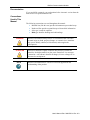
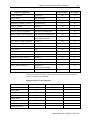
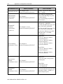
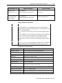
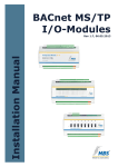
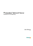
User’s Manual Pub. 0300274-01 Rev. A.0 Micro800™ BACnet Communication Module Catalog Number: 2080sc-BAC ii BACnet Communication Module User’s Manual Pub. 0300274-01 Rev. A.0 BACnet Communication Module iii Important Notes 1. Please read all the information in this owner’s guide before installing the product. 2. The information in this owner's guide applies to hardware Series A and firmware version 1.1 or later. 3. This guide assumes that the reader has a full working knowledge of the relevant processor. Notice The products and services described in this owner's guide are useful in a wide variety of applications. Therefore, the user and others responsible for applying the products and services described herein are responsible for determining their acceptability for each application. While efforts have been made to provide accurate information within this owner's guide, Spectrum Controls, Inc. assumes no responsibility for the accuracy, completeness, or usefulness of the information herein. Under no circumstances will Spectrum Controls, Inc. be responsible or liable for any damages or losses, including indirect or consequential damages or losses, arising out of either the use of any information within this owner's guide or the use of any product or service referenced herein. No patent liability is assumed by Spectrum Controls, Inc. with respect to the use of any of the information, products, circuits, programming, or services referenced herein. The information in this owner's guide is subject to change without notice. Limited Warranty Spectrum Controls, Inc. warrants that its products are free from defects in material and workmanship under normal use and service, as described in Spectrum Controls, Inc. literature covering this product, for a period of 1 year. The obligations of Spectrum Controls, Inc. under this warranty are limited to replacing or repairing, at its option, at its factory or facility, any product which shall, in the applicable period after shipment, be returned to the Spectrum Controls, Inc. facility, transportation charges prepaid, and which after examination is determined, to the satisfaction of Spectrum Controls, Inc., to be thus defective. This warranty shall not apply to any such equipment which shall have been repaired or altered except by Spectrum Controls or which shall have been subject to misuse, neglect, or accident. In no case shall the liability of Spectrum Controls, Inc. exceed the purchase price. The aforementioned provisions do not extend the original warranty period of any product which has either been repaired or replaced by Spectrum Controls, Inc. User’s Manual Pub. 0300274-01 Rev. A.0 iv BACnet Communication Module Microsoft and Microsoft Windows are registered trademarks of Microsoft Corporation. The Encompass logo, ControlLogix, RSLinx, RSLogix, and EtherNet/IP are trademarks of Rockwell Automation. Other brands and their products are trademarks or registered trademarks of their respective holders and should be noted as such. User’s Manual Pub. 0300274-01 Rev. A.0 BACnet Communication Module v Table of Contents IMPORTANT NOTES .............................................................................................................................................. III NOTICE ................................................................................................................................................................. III LIMITED WARRANTY ............................................................................................................................................. III PREFACE ............................................................................................................................................................... VI CHAPTER 1 MODULE OVERVIEW ......................................................................................................................... 1-1 SECTION 1.1 GENERAL DESCRIPTION .............................................................................................................................. 1-1 SECTION 1.2 ENVIRONMENT AND ENCLOSURE ................................................................................................................. 1-2 SECTION 1.3 PREVENT ELECTROSTATIC DISCHARGE ........................................................................................................... 1-4 SECTION 1.4 PARTS LIST .............................................................................................................................................. 1-5 SECTION 1.5 HARDWARE FEATURES ............................................................................................................................... 1-6 1.5.1 Serial I/O RJ-45 Connector ........................................................................................................................ 1-6 1.5.2 Ethernet Connector ................................................................................................................................... 1-7 SECTION 1.6 LED INDICATOR........................................................................................................................................ 1-8 SECTION 1.7 SOFTWARE UPGRADE ................................................................................................................................ 1-8 SECTION 1.8 MODULE DC POWER SPECIFICATIONS .......................................................................................................... 1-8 SECTION 1.9 MODULE CHASSIS EARTH GROUND .............................................................................................................. 1-8 CHAPTER 2 INSTALLATION AND WIRING ............................................................................................................. 2-1 SECTION 2.1 INSERT MODULE INTO CONTROLLER ............................................................................................................. 2-1 CHAPTER 3 CONFIGURING THE MODULE USING SOFTWARE ............................................................................... 3-1 SECTION 3.1 CONFIGURING THE SYSTEM......................................................................................................................... 3-4 SECTION 3.2 SETTING UP TAGS ..................................................................................................................................... 3-7 SECTION 3.3 EDITING XML TAG INFORMATION ............................................................................................................. 3-10 SECTION 3.4 GENERATING STRUCTURED TEXT................................................................................................................ 3-11 SECTION 3.5 USING THE CCW STRUCTURED TEXT EXAMPLE ............................................................................................. 3-12 3.5.1 Main function.......................................................................................................................................... 3-13 3.5.2 Function Blocks ....................................................................................................................................... 3-15 3.5.3 Memory Mapping ................................................................................................................................... 3-18 3.5.4 Data Type Range ..................................................................................................................................... 3-20 3.5.5 Tools ........................................................................................................................................................ 3-21 SECTION 3.6 VIEWING VERSION INFORMATION .............................................................................................................. 3-22 SECTION 3.7 VIEWING LOG INFORMATION .................................................................................................................... 3-22 SECTION 3.8 UPGRADING THE SOFTWARE ..................................................................................................................... 3-23 SECTION 3.9 SAVING CHANGES ................................................................................................................................... 3-23 SECTION 3.10 RELOADING SYSTEM CONFIGURATION ...................................................................................................... 3-24 CHAPTER 4 IMPLEMENTING THE BACNET PROTOCOL ......................................................................................... 4-1 SECTION 4.1 BACNET OBJECT TYPES.............................................................................................................................. 4-1 SECTION 4.2 PARAMETER OFFSET FOR MODULE BLOCK (0.00 [0] TO 0×1F [31]) ................................................................. 4-4 SECTION 4.3 USER INTERFACE OPTIONS .......................................................................................................................... 4-5 TECHNICAL ASSISTANCE ............................................................................................................................................... 4-5 User’s Manual Pub. 0300274-01 Rev. A.0 vi BACnet Communication Module Preface Read this preface to familiarize yourself with the rest of the manual. This preface covers the following topics: Who should use this manual How to use this manual Related publications Conventions used in this manual Rockwell Automation support Who Should Use This Manual Use this manual if you are responsible for designing, installing, programming, or troubleshooting control systems that use Allen-Bradley I/O and/or compatible controllers, such as CompactLogix and ControlLogix. How to Use This Manual As much as possible, we organized this manual to explain, in a task-by-task manner, how to install, configure, program, operate, and troubleshoot a control system using the Micro800™ BACnet Communication Module. Technical Support For technical support, please contact your local Rockwell Automation TechConnect Office for all Spectrum products. Contact numbers are as follows: United States: 1-440-646-6900 United Kingdom: 01908-635230 Australia: 1800-809929 Brazil: 011 (55) 113619-8800 Mexico: 001-888-365-8677 Europe: (49) 2104-960-630 or send an email to [email protected] User’s Manual Pub. 0300274-01 Rev. A.0 BACnet Communication Module vii Documentation If you would like a manual, you can download a free electronic version from the Internet at www.spectrumcontrols.com Conventions Used in This Manual The following conventions are used throughout this manual: Bulleted lists (like this one) provide information not procedural steps. Numbered lists provide sequential steps or hierarchical information. Italic type is used for emphasis. Bold type identifies headings and sub-headings: WARNING Identifies information about practices or circumstances that can lead to personal injury or death, property damage, or economic loss. Attentions help you to identify a hazard, avoid a hazard, and recognize the consequences. ATTENTION Actions ou situations risquant d’entraîner des blessures pouvant être mortelles, des dégâts matériels ou des pertes financières. Les messages « Attention » vous aident à identifier un danger, à éviter ce danger et en discerner les conséquences. NOTE Identifies information that is critical for successful application and understanding of the product. User’s Manual Pub. 0300274-01 Rev. A.0 viii BACnet Communication Module User’s Manual Pub. 0300274-01 Rev. A.0 Chapter 1 Module Overview Section 1.1 General Description The 2080sc-BAC Communication Module is a two-channel communication, plug-in module for use with Rockwell Automation Micro800™ systems. The plug-in module supports two channels of data communications: one channel is configured for RS-485, half duplex serial communications, and the other channel is configured for 10/100M Ethernet full duplex serial communications. After installation, the module is configured via the Ethernet port. By default, this is the port that the module uses to communicate with external devices such as other BACnet modules or personal computers. The module plugs into an extension slot on the PLC. The module interfaces with the controller via Asynchronous Parallel Interface (API), and communicates with other BACnet modules using the BACnet protocol. The module stores the data internally. During module setup, you map Micro800 PLC tags to BACnet tags so that the Micro800 system is able to receive, and respond to, BACnet messages. The BACnet protocol is configured to run on the Ethernet port by default. The data exchanged between a module and controller, or other BACnet modules, includes module configuration, configuration changes, interrupts from the module to the controller, module status queries from the controller, controller reset commands to the module, and other associated communications. The BACNet configuration software resides on the BACNet module. You use a User’s Manual Pub. 0300274-01 Rev. A.0 1-2 Chapter 1: Module Overview web browser to access this software to configure the parameters for the module. Configuring the communication module includes setting the User Interface password, entering the module device address, IP address, serial baud rate, and mapping PLC tags to BACnet tags. For complete information, refer to Chapter 3, Configuring the Module using Software. Power for the module is provided across the backplane. MS/TP signals from the field side are connected to the module via the 6-pin connector (RS-485). The Ethernet port handles BACnet/ IP traffic. Section 1.2 Environment and Enclosure WARNING This equipment is intended for use in a Pollution Degree 2 industrial environment, in overvoltage Category II applications (as defined in IEC publication 60664-1), at altitudes up to 2000 meters (6562 feet) without derating. This equipment is considered Group 1, Class A industrial equipment according to IEC/CISPR Publication 11. Without appropriate precautions, there may be potential difficulties ensuring electromagnetic compatibility in other environments due to conducted as well as radiated disturbance. This equipment is supplied as open-type equipment. It must be mounted within an enclosure that is suitably designed for those specific environmental conditions that will be present and appropriately designed to prevent personal injury resulting from accessibility to live parts. The enclosure must have suitable flame-retardant properties to prevent or minimize the spread of flame, complying with a flame spread rating of 5 VA, V2, V1, V0 (or equivalent) if non-metallic. The interior of the enclosure must be accessible only by the use of a tool. Subsequent sections of this publication may contain additional information regarding specific enclosure type ratings that are required to comply with certain product safety certifications. In addition to this publication, see: Industrial Automation Wiring and Grounding Guidelines, Allen-Bradley publication 1770-4.1, for additional installation requirements. NEMA Standards publication 250 and IEC publication 60529, as applicable, for explanations of the degrees of protection provided by different types of enclosure. User’s Manual Pub. 0300274-01 Rev. A.0 Chapter 1: Module Overview WARNING 1-3 Cet équipement est prévu pour fonctionner en environnement industriel avec une pollution de niveau 2, dans des applications de surtension de catégorie II (telles que définies dans la publication 60664-1 de la CEI) et à une altitude maximum de 2000 m sans déclassement. Cet équipement est considéré comme étant un équipement industriel du Groupe 1, classe A selon CEI/CISPR 11. En l’absence de précautions appropriées, des problèmes de compatibilité électromagnétique peuvent survenir dans des environnements résidentiels et dans d’autres environnement en raison de perturbations conduites et rayonnées. Cet équipement est fourni en tant qu’équipement de type « ouvert ». Il doit être installé à l’intérieur d’une armoire fournissant une protection adaptée aux conditions d’utilisation ambiantes et suffisante pour éviter toute blessure pouvant résulter d’un contact direct avec des composants sous tension. L’armoire doit posséder des propriétés ignifuges capables d’empêcher ou de limiter la propagation des flammes, correspondant à un indice de propagation de 5VA, V2, V1, V0 (ou équivalent) dans le cas d’une armoire non métallique. L’accès à l’intérieur de l’armoire ne doit être possible qu’à l’aide d’un outil. Cette armoire doit permettre des connexions d’alimentation par un système de câblage de Classe I, Division 2, conformément au code électrique national (NEC). Certaines sections de la présente publication peuvent comporter des recommandations supplémentaires portant sur les indices de protection spécifiques à respecter pour maintenir la conformité à certaines normes de sécurité. En plus de cette publication, consultez : La publication Rockwell Automation 17704.1, « Industrial Automation Wiring and Grounding Guidelines », pour d’autres critères d’installation ; La publication 250 de la norme NEMA ou la publication 60529 de la CEI, selon le cas, pour obtenir une description des indices de protection que fournissent les différents types d’armoires. User’s Manual Pub. 0300274-01 Rev. A.0 1-4 Chapter 1: Module Overview Section 1.3 Prevent Electrostatic Discharge WARNING Electrostatic discharge can damage integrated circuits or semiconductors if you touch bus connector pins. Follow these guidelines when you handle the module: Touch a grounded object to discharge static potential. Wear an approved wrist-strap grounding device. Do not touch connectors or pins on component boards. Do not touch circuit components inside the module. If available, use a static-safe work station. When not in use, keep the module in its static-shield box. WARNING Cet équipement est sensible aux décharges électrostatiques, lesquelles peuvent entraîner des dommages internes et nuire à son bon onctionnement. Conformez-vous aux directives suivantes lorsque vous manipulez cet équipement : Touchez un objet mis à la terre pour vous décharger de toute électricité statique éventuelle ; Portez au poignet un bracelet antistatique agréé ; Ne touchez pas les connecteurs ni les broches figurant sur les cartes des composants ; Ne touchez pas les circuits internes de l’équipement ; Utilisez si possible un poste de travail antistatique ; Lorsque vous n’utilisez pas l’équipement, stockez-le dans un emballage antistatique. WARNING To comply with the CE Low Voltage Directive (LVD), all connected I/O must be powered from a source compliant with the following: Safety Extra Low Voltage (SELV) or Protected Extra Low Voltage (PELV). User’s Manual Pub. 0300274-01 Rev. A.0 Chapter 1: Module Overview WARNING 1-5 Pour se conformer à la Directive basse tension CE, cet équipement doit être alimenté à partir d’une source ayant les caractéristiques suivantes: très basse tension de sécurité (TBTS) ou très basse tension de protection (TBTP). Section 1.4 Parts List Your package contains one Micro800 BACnet Communication Module, installation screws, and one Quick Start Guide. You can choose to wire the plug-in before inserting it into the controller, or wire it once the module is secured in place. WARNING This equipment is considered Group 1, Class A industrial equipment according to IEC/CISPR 11. Without appropriate precautions, there may be difficulties with electromagnetic compatibility in residential and other environments due to conducted and radiated disturbance. Be careful when stripping wires. Wire fragments that fall into the controller could cause damage. Once wiring is complete, make sure the controller is free of all metal fragments before removing the protective debris strip. Do not wire more than 2 conductors on any single terminal. If you insert or remove the plug-in module while power is on, an electrical arc can occur. This could cause an explosion in hazardous location installations. Be sure that power is removed or the area is nonhazardous before proceeding. Cable length should be less than 10 meters (30 feet). Do not insert or remove the plug-in module while power is applied; otherwise, permanent damage to equipment may occur. User’s Manual Pub. 0300274-01 Rev. A.0 1-6 Chapter 1: Module Overview WARNING Cet équipement est considéré comme étant un équipement industriel du Groupe 1, classe A selon CEI/CISPR 11. En l’absence de precautions appropriées, des problèmes de compatibilité électromagnétique peuvent survenir dans des environnements résidentiels et dans d’autres environnements en raison de perturbations conduites et rayonnées. Soyez vigilant en dénudant les fils. Tout fragment de fil tombé dans l’automate risquerait de le détériorer. Une fois le câblage terminé, veillez à ce que l’automate ne présente aucun copeau de métal avant de retirer la bande de protection. Ne câblez pas plus de 2 conducteurs sur une même borne. L’insertion ou le retrait du module enfichable sous tension peut provoquer un arc électrique, susceptible de provoquer une explosion dans un environnement dangereux. Assurez-vous que l’alimentation est coupée ou que l’environnement est classé non dangereux avant de poursuivre. La longueur de câble devrait être inférieure à 10 mètres. N’insérez pas et ne retirez pas le module enfichable quand l’équipement est sous tension, au risque de provoquer des dommages irrémédiables à l’équipement. Section 1.5 Hardware Features The module plugs into, and communicates with, a controller in the Micro800 family. Communication I/O signals are connected to the module through a 6-pin terminal block and an RJ-45 connector: 1.5.1 Serial I/O RJ-45 Connector NOTE Pins in following table are listed from 6 to 1 to match connector on front panel of module. User’s Manual Pub. 0300274-01 Rev. A.0 Chapter 1: Module Overview 1-7 The six-pin Connector pinouts are as follows: Pin Signal 6 MSTP+ 5 GND 4 GND 3 LOAD- 2 LOAD+ 1 MSTP- 1.5.2 Ethernet Connector The Ethernet connector has a default MAC address that may be changed during setup. The Ethernet connector may be used as an external communication port to a personal computer or to another BACnet module. The Ethernet connector is also used to configure the module. The default IP address for the module is 169.254.3.3. If the module is already configured, software is available for you to detect the address. See Chapter 3, Configuring the Module Using Software. Pinouts for the connector (crossover) are: 2080sc-BACnet Module Personal Computer 1 TX+ 2 TX3 RX+ 4 Not connected 5 Not connected 6 RX7 Not connected 8 Not connected 8 Not connected 7 Not connected 6 TX5 Not connected 4 Not connected 3 TX+ 2 RX1 RX+ User’s Manual Pub. 0300274-01 Rev. A.0 1-8 Chapter 1: Module Overview Section 1.6 LED Indicator A single LED indicator is provided with the module. The LED is green for ON. The LED blinks in case of a fault. Section 1.7 Software Upgrade The module software can be upgraded in the field. Section 1.8 Module DC Power Specifications The controller provides two Power Supplies to the module: 3.3 Volts (3.0 V Min, 3.6 V Max), Current Rating: 40 mA 24 Volts (20.4 V Min, 26.4 V Max), Current Rating: 50 mA You may not use an external power source to power the module. Refer to the specifications in the Appendix for further information. Section 1.9 Module Chassis Earth Ground The Micro800 controller does not have a chassis (earth) ground. The 2080scBACnet module connects to an isolated ground, ISO-GND, which is exclusive to the external communication interfaces. The purpose of the isolated ground is to prevent possible interference on the I/O channels from permanently damaging the module itself. User’s Manual Pub. 0300274-01 Rev. A.0 Chapter 2 Installation and Wiring Section 2.1 Insert Module into Controller Follow the instructions to insert and secure the plug-in module to the controller. WARNING Electrostatic discharge can damage integrated circuits or semiconductors if you touch bus connector pins. Follow these guidelines when you handle the module: Touch a grounded object to discharge static potential. Wear an approved wrist-strap grounding device. Do not touch connectors or pins on component boards. Do not touch circuit components inside the module. If available, use a static-safe work station. When not in use, keep the module in its static-shield box. WARNING Cet équipement est sensible aux décharges électrostatiques, lesquelles peuvent entraîner des dommages internes et nuire à son bon onctionnement. Conformez-vous aux directives suivantes lorsque vous manipulez cet équipement : Touchez un objet mis à la terre pour vous décharger de toute électricité statique éventuelle ; Portez au poignet un bracelet antistatique agréé ; Ne touchez pas les connecteurs ni les broches figurant sur les cartes des composants ; Ne touchez pas les circuits internes de l’équipement ; Utilisez si possible un poste de travail antistatique ; Lorsque vous n’utilisez pas l’équipement, stockez-le dans un emballage antistatique. User’s Manual Pub. 0300274-01 Rev. A.0 2-2 Chapter 2: Installation and Wiring 1. Position the plug-in module with the terminal block facing the front of the controller as shown. The 2080sc-BACnet module has a different front panel setup, but the installation in the controller is the same: 2. Snap the module into the module bay. 3. Using a screwdriver, tighten the supplied, self-tapping screw to torque specifications. 4. Wire the module using the 6-pin connector as shown: OR Connect an RJ-45 Ethernet cable and connector between a personal computer and the connector on the front of the module. Set up the tag mapping using the software described in Chapter 3. User’s Manual Pub. 0300274-01 Rev. A.0 Chapter 3 Configuring the Module using Software Before configuring the module with the BACnet software: 1. Install your BACnet module in the Rockwell Micro800 controller. 2. Connect a personal computer to an Ethernet switch or network hub. Connect the Ethernet port on the personal computer to the Ethernet switch or hub. 3. Connect another cable between the hub and the Ethernet connector on the BACnet module. Personal Computer Ethernet Hub or Switch BACNet Module Micro800 PLC Once the module is set up: 1. Change the personal computer IP address to a static IP address. If you need additional assistance with changing your personal computer’s IP address, refer to the Windows Help documentation or use the information provided next to access the module. 2. Map tags between the Micro800 PLC and the BACnet module. 3. Generate the mapping file between the PLC and the module. 4. Download the map file to the module. 5. Generate the structured text to be used when programming the PLC. After you have configured your system, the BACnet module listens on Ethernet port number, 0×BAC0, for data from the network and handles the data according to the BACnet protocol. Detailed instructions for each step of this process are provided below. User’s Manual Pub. 0300274-01 Rev. A.0 3-2 Chapter 3: Configuring the Module To access the software on your module: 1. Access your PC local area connection properties dialog as shown below: Start:Control Panel:Network and Sharing Center:Change Adapter Settings:Local Area Connection Settings:Properties. 2. From the Local Area Connection n Properties dialog, select the Internet Protocol Version 4 (TCP/IPv4) option: 3. Change the settings to the equivalent settings for your personal computer as shown next: 4. Open a web browser and type in the IP default address of your BACnet module, which is 169.254.3.3. User’s Manual Pub. 0300274-01 Rev. A.0 Chapter 3: Configuring the Module 3-3 The following dialog appears: 5. Type the password spectrum into the Password field and click Submit. The BACnet configuration dialog appears. The examples shown below use IP addresses that have been reconfigured to work on a different network from the default IP address : 6. View or modify the following options: System Configuration. Use to set up password, date and time, device, and LAN settings. Tag Setup. Use to set up tag mapping between your Micro800 controller and the BACnet Communications module. User’s Manual Pub. 0300274-01 Rev. A.0 3-4 Chapter 3: Configuring the Module Section 3.1 Configuring the System System configuration includes setting up or changing your system password, setting the date and time, choosing your device, and setting up the LAN. To set up or change system configuration settings: 1. Access the System Configuration tab: 2. View or specify the following options: Password. The software ships with a default password, spectrum. You log onto the module software User Interface with this password when you first log onto the module. However, Spectrum Controls, Inc. highly recommends that you immediately change this password to one of your own choosing. There are two passwords: - - Login Password. This is the password you use to log onto software which ships with the BACnet module. The default user password is spectrum. If you reset your module to factory default settings, this is the password that you use to log in. Reset/DCC Password. BACnet has a remote reset command. When the module receives the remote reset command, it reboots itself. You use this password as the BACnet reset message password to reboot the module. Date/Time. At startup, the module retrieves the NIST time, if network is set to retrieve it. If connected to the Internet at that point, the module’s time is set from the server. The date and time are held for 2 to 3 days if power is lost. If needed, you may manually enter the date and time: User’s Manual Pub. 0300274-01 Rev. A.0 Chapter 3: Configuring the Module - 3-5 Date. Enter the date as MM/DD/YYYY where MM is month, DD is day, and YYYY is year. If necessary, select the date from the calendar provided. - Time. 24-hour time format. Enter the time in hours, minutes, and seconds. Device. Enter the device instance and name. The device instance is the unique ID of a device used by BACnet. Default Device ID is #200121. All messages directed to the module are addressed to this ID. The allowable range is from 1 to 4,194,034. When the protocol wishes to talk to a device, the master sends out a ‘WhoIs n’ message1, where n is a Device ID. The device responds with an ‘I-Am n’ and provides the master with either an IP address if the device is an Ethernet type, or a MAC address if the device is an MS/TP type (RS-485). The master is then able to talk to the device: - Instance. Specify the device instance entry. - Name. Enter the device name. LAN. Specifies LAN type and communication parameters for the LAN type selected. After saving your values, you must cycle power on the module to allow the new settings to take effect. 1 Technically, the module sends a ‘WhoIs m to n’ message, where m is the lower limit, and n is the upper limit. It may also send a ‘WhoIs null’, which is a broadcast to all reachable devices, and will bind all responding devices’ addresses to their device ID. User’s Manual Pub. 0300274-01 Rev. A.0 3-6 Chapter 3: Configuring the Module The module and personal computer’s IP addresses must also be on the same network to allow the two devices to communicate: - BACnet/IP. When you set up your module to use an Ethernet physical interface, specify a UDP port number for BACnet/IP, IP address, Subnet Mask, and Gateway. The UDP port communicates between the PC and the module. It is used to retrieve the module’s IP address and password authentication: View or specify the following options: UDP Port: 0x XXXN. Default address: 0×BAC0 IP Address. Enter IP address. Example: 10.0.0.91 Subnet Mask. Enter subnet mask. Default mask value is 255.255.255.0 Gateway. Enter gateway address. Example: 10.0.0.1 - MS/TP. (Master-Slave/Token Ring Passing.) - This connection is set up using the 6-pin connector on the front panel of the BACnet module. Mstp+ is RS485+; Mtsp- is RS-485-: When you set up your module to use an MS/TP physical interface, which is RS-485, half-duplex communication, you specify the following fields: MAC Address. Enter the module MS/TP MAC address. Default suggested value is any value between 1 and 127. If there are more devices on User’s Manual Pub. 0300274-01 Rev. A.0 Chapter 3: Configuring the Module 3-7 your MS/TP network you will need to determine what MAC address to use that makes this device unique on your network. You will need to exercise care to avoid entering duplicate MAC addresses in your device network. Max Masters. In a token ring network, each node is responsible for searching for the next node and passing the token to it. Max Masters is the maximum MAC address this module searches for. For example, if this module’s MAC address is 5 and the Max Master value is 20, this module will poll MAC address from 6 to 20 for the next node. Enter the Max Masters address. Default suggested value is 127 (range is 1 to 127). Max Number of Frames. In a token ring network, when a node receives a token, it needs to pass the token to the next node in a timely manner. Setting Max Number of Frames to 20 means when this module receives the token, it can send out a maximum of 20 messages before it has to pass the token to the next node. A good starting value to enter is 20. If you have a very busy network, you may need to reduce this number to allow your network to function optimally. Baudrate. Select an MS/TP communication baud rate (9600, 19200, 38400, or 76800): Section 3.2 Setting Up Tags You use this dialog to map PLC tags to BACnet objects. The 2080sc-BACnet Communication Module supports BACnet AnalogInput (AI), AnalogOutput (AO), BinaryInput (BI), and BinaryOutput (BO) objects. When you map a BACnet object to a PLC tag, you should match the same or similar data types (covered later in this chapter). For example, map PLC data type BOOL to BACnet binary input or output objects. Other PLC data types can be mapped to BACnet analog input or analog output objects. If a BACnet object is AnalogInput, the module reads the mapped PLC tag and sends the data back to the AI read property request. If a BACnet object is AnalogOutput, the module writes the mapped PLC tag when it receives an AO write property request. User’s Manual Pub. 0300274-01 Rev. A.0 3-8 Chapter 3: Configuring the Module To set up tag mapping between the Micro800 PLC and BACnet objects: 1. Select the Tag Setup tab. The Tag Setup dialog appears: 2. View or specify the following options: Add Tags. To add a tag, click the Add Tag icon: A new row is added to the tag list. Enter the tag data for each of the editable fields in the PLC and BACnet mapping fields as follows: User’s Manual Pub. 0300274-01 Rev. A.0 - Tag Name. Enter the PLC variable tag name. Click on the field and type in the name: - Data Type. Select the PLC variable data type. Click on the field and select the correct data type associated with the tag: Chapter 3: Configuring the Module 3-9 - Attribute. Enter the PLC variable attribute. - Object Name. Enter the BACnet object name. Use a meaningful description, such as Damper Angle. - Object Type. Click on the field and select the relevant object type for the PLC tag: - Object ID. This is the BACnet object instance. Valid range is from 0 to 63, which means you can define 64 object instances of each object type. Each object is uniquely defined by object-instance and type. Support is provided for 256 BACnet objects. Click on the field and type in the ID value. - Present Value. Not editable (from user interface). When the BACnet module requests the PLC report a specific value, the PLC returns the present value in the specific index. Example: When the PLC receives a BACnet command to report the present value of Analog Value Index 1, the PLC sends the present value of AV 1 back to the requester. This value is displayed in the Present Value column. Delete Tags. To delete a tag, click the Delete Tag button: The selected tag row is deleted. Reload Tags. Reloads tag preset values. Save Tags. Saves tag changes. You have to save changes before you may generate structured text from the tag information. Edit XML. Allows you to manually edit tag information in XML format. See Editing XML Tag Information next. Generate Structured Text. Converts tag information to CCW structured text. See Generating Structured Text later in this chapter. User’s Manual Pub. 0300274-01 Rev. A.0 3-10 Chapter 3: Configuring the Module Section 3.3 Editing XML Tag Information You normally modify tags through the software’s user interface. However, the module uses an XML file format to save the tag mapping information. To save time, you may also modify the XML file directly. NOTE When modifying XML directly, be sure to make a backup of your original file first. Otherwise you may find errors or accidental deletions of entries cause problems with your file. Once you save the file, the changes are permanent. NOTE To expedite the tag mapping process, you may copy and paste PLC tags from CCW directly into the XML window. Use this feature when you are editing a large number of tags. This module uses XML file format to save the tag mapping. To view all the variables in the XML file: 1. Click Edit XML: The Tags dialog appears with all the tags in the list in XML format: 2. If needed, manually modify individual entries in the XML file. User’s Manual Pub. 0300274-01 Rev. A.0 Chapter 3: Configuring the Module 3-11 Example. In the above Tags list, you may change: <Name>__IO_EM_DO_00</Name> TO <Name>__IO_EM_DO_123</Name> manually. 3. To implement the changes, click Submit. The name changes to __IO_EM_DO_123. Section 3.4 Generating Structured Text Rockwell Connected Component Workshop (CCW) software interfaces with the BACnet module. Tag mapping is executed through CCW, which reads and writes to the BACnet module using CCW structured text code . When you finish mapping tags, you convert the tag information to structured text code. 1. To convert tag information to structured text code, add your tags using the Tags dialog: 2. From the Tags dialog, click Generate Structured Text: User’s Manual Pub. 0300274-01 Rev. A.0 3-12 Chapter 3: Configuring the Module The software generates the CCW structured text and shows the text in the Structured Text dialog: 3. Copy the structured text and paste into your CCW software as Main function. Section 3.5 Using the CCW Structured Text Example Spectrum Controls, Inc. provides a sample CCW project with a sample Main function and a Function block named BACNET_Convert in a zipped project file, BACNET_Utilities.zip, downloadable from the Spectrum Controls website. If you have the same PLC as the sample project, you may directly use this project. Otherwise this project can only be referenced in relation to the PLC in which you installed your BACnet module. There is no project portability among different PLCs. You have to create a new project if you are using a different Micro830 PLC. The CCW sample project consists of a Main function and one, user defined, function block. The Main function is generated by the Module when you click Generate Structured Text on the Tags dialog. The Function block BACNET_Convert is provided in the sample project. User’s Manual Pub. 0300274-01 Rev. A.0 Chapter 3: Configuring the Module 3-13 This function block does not need to change when you make a tag mapping change. NOTE There is no defined behavior for the module when the controller enters Program Mode, remotely or manually. When placed in Program Mode, the module will still respond to BACnet requests with the same functionality as exists in normal operation, with the exception that PLC will not receive updated Output values from the module, nor will it update Input values to the module. Once the controller leaves Program mode and re-enters Run mode, the PLC's tags mapped to Output objects get updated to match the module's stored value, and the module updates Input values to be consistent with the PLC. 3.5.1 Main function Below is an example of generated Main function structured text. This example shows how an analog output variable is read from module, and an analog input variable is written to the module from CCW. Review the following example for information about how to implement this. User’s Manual Pub. 0300274-01 Rev. A.0 3-14 Chapter 3: Configuring the Module The first step is to create Local Variables for the Main program. The second step is to paste in the structured text generated by the Module configuration user interface to the Main program of the CCW. Below is an example of this Main program. A variable called tag1 is converted to ULINT variable bacnet_convert_var and then placed at offset 0 of the byte array table because you are writing AnalogInput 0. If it is AnalogInput 1, the offset will be 8 as each BACNET object instance takes 8 bytes. Variable bacnet_convert_mode is 1. This means this is a write operation. 0 identifies a read operation: (* 0, AnalogInput, aiaaa *) bacnet_convert_var := ANY_TO_ULINT(tag1); bacnet_convert_offset := 0; bacnet_convert_mode := 1; bacnet_convert_fn(bacnet_convert_offset, bacnet_convert_var, bacnet_convert_mode); (* Write Input Table to Module *) bacnet_module_address := 112; bacnet_module_datalen := 8; bacnet_module_write_fn(TRUE, BACNET_MODULE_SLOT, bacnet_module_address, bacnet_module_datalen, bacnet_convert_fn.bac_raw_tbl); User’s Manual Pub. 0300274-01 Rev. A.0 Chapter 3: Configuring the Module 3-15 Similarly, for Analog Output, a read is performed to read the whole analog table to bac_raw_tbl, defined in function block bacnet_convert_fn. Next, individual AnalogOutput objects are to be written to the variable after conversion from ULINT to a tag data type. (* Read Output Table from Module *) bacnet_module_read_fn(TRUE, BACNET_MODULE_SLOT, bacnet_module_address, bacnet_module_datalen, bacnet_convert_fn.bac_raw_tbl); (* 0, AnalogOutput, ao0 *) bacnet_convert_mode := 0; bacnet_convert_offset := 0; bacnet_convert_fn(bacnet_convert_offset, bacnet_convert_var, bacnet_convert_mode); tag4 := ANY_TO_INT(bacnet_convert_fn.tmp_raw_var); 3.5.2 Function Blocks A user-defined function block has to be defined by the user (yourself if that is the case). Local variables for this function block are similar to those shown below. After creating the local variables, you need to create a function block called BACNET_Convert and paste the code below to this function block. (* if param_mode = 0 convert byte array bac_raw_tbl to ULINT variable tmp_raw_var This is for Analog Output Table *) IF param_mode = 0 THEN User’s Manual Pub. 0300274-01 Rev. A.0 3-16 Chapter 3: Configuring the Module tmp_index := param_offset; tmp_raw_var := 0; tmp_raw_var := tmp_raw_var + ANY_TO_ULINT(bac_raw_tbl[tmp_index]) * 1; tmp_index := tmp_index + 1; tmp_raw_var := tmp_raw_var + ANY_TO_ULINT(bac_raw_tbl[tmp_index]) * 16#100; tmp_index := tmp_index + 1; tmp_raw_var := tmp_raw_var + 16#10000; tmp_index := tmp_index + 1; tmp_raw_var := tmp_raw_var + 16#1000000; tmp_index := tmp_index + 1; tmp_raw_var := tmp_raw_var + 16#100000000; tmp_index := tmp_index + 1; tmp_raw_var := tmp_raw_var + 16#10000000000; tmp_index := tmp_index + 1; tmp_raw_var := tmp_raw_var + 16#1000000000000; tmp_index := tmp_index + 1; tmp_raw_var := tmp_raw_var + 16#100000000000000; ANY_TO_ULINT(bac_raw_tbl[tmp_index]) * ANY_TO_ULINT(bac_raw_tbl[tmp_index]) * ANY_TO_ULINT(bac_raw_tbl[tmp_index]) * ANY_TO_ULINT(bac_raw_tbl[tmp_index]) * ANY_TO_ULINT(bac_raw_tbl[tmp_index]) * ANY_TO_ULINT(bac_raw_tbl[tmp_index]) * (* if param_mode == 1 convert ULINT variable tmp_raw_var to byte array bac_raw_tbl This is for Analog Input Table *) ELSIF param_mode = 1 THEN tmp_index := param_offset; tmp_raw_var := param_var; bac_raw_tbl[tmp_index] := ANY_TO_BYTE(tmp_raw_var); tmp_raw_var := tmp_raw_var / 256; tmp_index := tmp_index + 1; bac_raw_tbl[tmp_index] := ANY_TO_BYTE(tmp_raw_var); tmp_raw_var := tmp_raw_var / 256; tmp_index := tmp_index + 1; bac_raw_tbl[tmp_index] := ANY_TO_BYTE(tmp_raw_var); tmp_raw_var := tmp_raw_var / 256; tmp_index := tmp_index + 1; bac_raw_tbl[tmp_index] := ANY_TO_BYTE(tmp_raw_var); tmp_raw_var := tmp_raw_var / 256; tmp_index := tmp_index + 1; bac_raw_tbl[tmp_index] := ANY_TO_BYTE(tmp_raw_var); tmp_raw_var := tmp_raw_var / 256; tmp_index := tmp_index + 1; bac_raw_tbl[tmp_index] := ANY_TO_BYTE(tmp_raw_var); tmp_raw_var := tmp_raw_var / 256; tmp_index := tmp_index + 1; bac_raw_tbl[tmp_index] := ANY_TO_BYTE(tmp_raw_var); tmp_raw_var := tmp_raw_var / 256; tmp_index := tmp_index + 1; bac_raw_tbl[tmp_index] := ANY_TO_BYTE(tmp_raw_var); tmp_index := tmp_index + 1; (* if param_mode == 2 This is for Binary Output Table *) ELSIF param_mode = 2 THEN tmp_index := param_offset / 8; tmp1 := MOD(param_offset, 8); tmp2 := ANY_TO_DINT(bac_raw_tbl[tmp_index]); tmp2 := SHR(tmp2, tmp1); User’s Manual Pub. 0300274-01 Rev. A.0 Chapter 3: Configuring the Module 3-17 tmp2 := AND_MASK(tmp2, 1); IF tmp2 = 1 THEN tmp_raw_var := 1; ELSE tmp_raw_var := 0; END_IF; (* if param_mode == 3 This is for Binary Input Table *) ELSIF param_mode = 3 THEN tmp_index := param_offset / 8; tmp1 := MOD(param_offset, 8); tmp2 := 1; tmp2 := SHL(tmp2, tmp1); tmp1 := ANY_TO_DINT(bac_raw_tbl[tmp_index]); IF param_var = 0 THEN (* set 0 *) tmp1 := NOT_MASK(tmp1); tmp1 := OR_MASK(tmp1, tmp2); tmp1 := NOT_MASK(tmp1); ELSE (* set 1 *) tmp1 := OR_MASK(tmp1, tmp2); END_IF; bac_raw_tbl[tmp_index] := ANY_TO_BYTE(tmp1); ELSE (* do nothing *) (* tmp_index := param_offset / 8; *) END_IF; In the Main function, you see a variable called bacnet_convert_fn type as BACNET_Convert is called. This is how the Main function calls the user-defined function block. Since CCW has many different types of data types, this function block is able to convert all the different data types to a bytes array. When CCW reads from the module, the module fills this bytes array first. Then CCW reads the array and converts the data to different data types. When CCW writes to the module, CCW converts a variable to this 8 bytes array, and writes it to the module. The following examples shows how an analog output variable is read from module, and an analog input variable is written to the module from CCW. Structured text is generated by the module. A variable called tag1 is converted to ULINT variable bacnet_convert_var and then placed at offset 0 of the byte array table because you are writing AnalogInput 0. If it is AnalogInput 1, the offset will be 8 as each BACNET object instance takes 8 bytes. Variable bacnet_convert_mode is 1 means this is a write operation. 0 indicates a read operation. (* 0, AnalogInput, aiaaa *) bacnet_convert_var := ANY_TO_ULINT(tag1); bacnet_convert_offset := 0; bacnet_convert_mode := 1; bacnet_convert_fn(bacnet_convert_offset, bacnet_convert_var, bacnet_convert_mode); User’s Manual Pub. 0300274-01 Rev. A.0 3-18 Chapter 3: Configuring the Module (* Write Input Table to Module *) bacnet_module_address := 112; bacnet_module_datalen := 8; bacnet_module_write_fn(TRUE, BACNET_MODULE_SLOT, bacnet_module_address, bacnet_module_datalen, bacnet_convert_fn.bac_raw_tbl); Similarly, for Analog Output, a read operation is performed to read the whole analog table to bac_raw_tbl defined in function block bacnet_convert_fn. Then individual AnalogOutput objects are written to the variable after conversion from ULINT to a tag data type. (* Read Output Table from Module *) bacnet_module_read_fn(TRUE, BACNET_MODULE_SLOT, bacnet_module_address, bacnet_module_datalen, bacnet_convert_fn.bac_raw_tbl); (* 0, AnalogOutput, ao0 *) bacnet_convert_mode := 0; bacnet_convert_offset := 0; bacnet_convert_fn(bacnet_convert_offset, bacnet_convert_var, bacnet_convert_mode); tag4 := ANY_TO_INT(bacnet_convert_fn.tmp_raw_var); 3.5.3 Memory Mapping This section discusses memory mapping between a BACnet module and the PLC. The BACnet module has internal memory that is mapped to the PLC memory range. On the PLC, each slot has 2 Kbytes of memory. The internal RAM in the Module is arranged as below. This section is for reference only as all the mappings are automatically generated in the structured text. BACnet Binary Input Block (0×60 – 0×67) Register Name Addr. Comments Default R/W From PLC R/W From Module BAC_BI 0×60 – 0×67 BACnet Binary Input data (tags 0 – 63) 0 W R Each bit of the BACnet Binary Input represents a true/false value for one BACnet Binary Input object. This block supports up to 64 such objects. BACnet Binary Output Block (0×400 – 0×407) Register Name Addr. Comments Default R/W From PLC R/W From Module BAC_BO 0×400 – 0×407 BACnet Binary Output data (tags 0 – 63) 0 W R User’s Manual Pub. 0300274-01 Rev. A.0 Chapter 3: Configuring the Module 3-19 Each bit of the BACnet Binary Value represents a true/false value for one BACnet Binary Value object. This block supports up to 64 such objects. BACnet Analog Input 1 Block (0×100 – 0×1FF) Register Name Addr. Comments Default R/W From PLC R/W From Module BAC_AI_0 0×100 – 0×107 BACnet Analog Input tag 0 0 W R BAC_AI_1 0×108 – 0×10F BACnet Analog Input tag 1 0 W R … … … … … … BAC_AI_31 0×1F8 – 0×1FF BACnet Analog Input tag 31 0 W R This block is for the first 32 BACnet Analog Input tag values. BACnet Analog Input objects are read from a user-specified PLC variable, written by the PLC to the module, and then made available via the BACnet stack as a read-only value. BACnet Analog Input 2 Block (0×200 – 0×2FF) Register Name Addr. Comments Default R/W From PLC R/W From Module BAC_AI_32 0×200 – 0×207 BACnet Analog Input tag 32 0 W R … … … … … … BAC_AI_63 0×2F8 – 0×2FF BACnet Analog Input tag 63 0 W R This block is for the last 32 BACnet Analog Input tag values. BACnet Analog Output 1 Block (0×500 – 0×5FF) Register Name Addr. Comments Default R/W From PLC R/W From Module BAC_AO_0 0×500 – 0×507 BACnet Analog Output tag 0 0 R W BAC_AO_1 0×508 – 0×50F BACnet Analog Output tag 1 0 R W … … … … … … User’s Manual Pub. 0300274-01 Rev. A.0 3-20 Chapter 3: Configuring the Module Register Name Addr. Comments Default R/W From PLC R/W From Module BAC_AO_31 0×5F8 – 0×5FF BACnet Analog Output tag 31 0 R W This block is for the first 32 BACnet Analog Output tag values. BACnet Analog Output objects are made available via the BACnet stack as a writable value that is then written by the module to the PLC. The data are then copied into a user-specified PLC variable. BACnet Analog Output 2 Block (0×600 – 0×6FF) Register Name Addr. Comments Default R/W From PLC R/W From Module BAC_AO_32 0×600 – 0×607 BACnet Analog Output tag 32 0 R W … … … … … … BAC_AO_63 0×6F8 – 0×6FF BACnet Analog Output tag 63 0 R W This block is for the last 32 BACnet Analog Output tag values. Module Block (0×00 – 0×1F) Register Name Addr. Comments Default R/W From PLC R/W From Module MOD_ID_LO 0×00 Module ID 193 R W MOD_ID_HI 0×01 0 R W VENDOR_ID_LO 0×02 58 R W VENDOR_ID_HI 0×03 0 R W PRODUCT_TYPE_LO 0×04 10 R W PRODUCT_TYPE_HI 0×05 0 R W Vendor ID 3.5.4 Data Type Range The maximum and minimum value of the tags is decided by the PLC data type and it is also limited by data storage and conversion. BOOL TRUE or FALSE SINT -128 to 127 USINT 0 to 255 BYTE 0 to 255 INT -32768 to 32767 UINT 0 to 65535 WORD 0 to 65535 DINT -2147483648 to 2147483647 UDINT 0 to 429467295 User’s Manual Pub. 0300274-01 Rev. A.0 Chapter 3: Configuring the Module DWORD LINT ULINT LWORD REAL LREAL 3-21 0 to 429467295 -1e18 to 1e182 0 to 1e18 0 to 1e18 -1e18 to 1e183 -1e18 to 1e18 3.5.5 Tools Spectrum Controls, Inc. provides multiple Windows command-line executables you may use to communicate with the module. These utilities are compiled from an open source BACnet stack. The tools require an Ethernet-to-BACnet router. This gives you the ability to send BACnet messages across the BACnet RS-484 network for easier troubleshooting. You can find the source code on sourceforge at http://sourceforge.net/projects/bacnet/files/bacnet-stack/ Setup To access the BACnet/IP traffic, set the module IP address using a network address that on the same network as the PC IP address. To access the MS/TP connection on the module, set the baud rate and other parameters using the User Interface. Then connect a BACnet router to your setup. The router converts BACnet/IP packets to MS/TP packets that are then routed to the module. Set the router IP address using a network address that is also on the host network. WhoIs The executable, bacwi.exe, looks for who is on the BACnet network. Example: “bacwi -1” will find all the nodes on the BACnet network. ReadProperty This executable, bacrp.exe, will read the property of the module. Examples. To read AI 1 present value, do this – bacrp 200121 0 1 85 {param 1} – 200121. This is a module instance number. {param 2} – 0. This is the object type. Object type is defined as: BI(3), BO(4), AI(0), AO(1). {param 3} – 1. This is the object instance. {param 4} – 85. This is the property. Example: present value(85), object name(77). WriteProperty This executablebacwp.exe will write the property of the module. 2 3 LINT and ULINT cannot have the same upper range. LREAL has twice as many bits to work with than REAL User’s Manual Pub. 0300274-01 Rev. A.0 3-22 Chapter 3: Configuring the Module Examples: To write BO 3 present value to 1, do this – “bacwp 200121 4 3 85 15 1 9 1” {param 1} – 200121. This is the module instance number. {param 2} – 0. This is the object type. Object type is defined as: BI (3), BO(4), AI(0), AO(1). {param 3} – 3. This is the object instance. {param 4} – 85. This is the property (present value 85, property array 87, object name 77, object list 76). {param 5} – 15. This is the priority. BACnet property write uses priority, levels from 1 to 16. The module keeps a table for those priorities; high priority overrides lower priority. So if there is a value in priority 14, priority 15 value has no effect. {param 6} – -1. This is the index. Use -1 for a single property write. {param 7} – 9. Value type. Use 9 for BI and BO; use 4 for AI and AO. {param 8} – 1. Value. This is the actual value to be written to the tag. Section 3.6 Viewing Version Information To view the current version of your software: 1. From the main software dialog, click Version Info: The Version Info dialog appears: The current software version is listed. 2. To exit, click OK. Section 3.7 Viewing Log Information To view current Log Information: 1. From the main software dialog, click Show Log: The Log Data dialog appears: User’s Manual Pub. 0300274-01 Rev. A.0 Chapter 3: Configuring the Module 3-23 The Ethernet hardware MAC address is listed. 2. To exit, click OK. Section 3.8 Upgrading the Software To upgrade to a new version of software: 1. Navigate to the correct BACnet location on the Spectrum Controls, Inc. web site (www.spectrumcontrols.com), and download the software upgrade to your personal computer. The software upgrade file will have a .UPT file extension. 2. From the main software dialog, click Upgrade: 3. Use the dialog that opens to navigate to where you downloaded the upgrade file, and click on the file. The software upgrades and the module reboots once the upgrade is complete. Section 3.9 Saving Changes To save changes made to the software fields: 1. From the main software dialog, click Save: User’s Manual Pub. 0300274-01 Rev. A.0 3-24 Chapter 3: Configuring the Module Confirm you wish to save the data: To save the data, click Yes. To cancel the data save, click No. 2. If you select Yes, the software saves the changes to the system configuration on the module. Section 3.10 Reloading System Configuration To reload the system configuration from the module: 1. From the main software dialog, click Reload: 2. The software reloads the system configuration from the module into the software. User’s Manual Pub. 0300274-01 Rev. A.0 Chapter 4 Implementing the BACnet Protocol This chapter describes the BACnet protocol and its implementation in the BACnet Communications Module: BACnet Protocol Requirements Tag Mapping API Address Mapping and other considerations Section 4.1 BACnet Object Types The following data shows the supported BACnet object types and the properties supported for each object type. Each table also includes the property data type, the identifier number, and whether the property is read or read/write. Analog Input-BACnetObjectType = 0 Properties Supported Property Data Type Identifier Read/Write Object_Identifier BACnetObjectIdentifier 75 R Object_Name CharacterString 77 R Object_Type BACnetObjectType 79 R Present_Value REAL 85 R Status_Flags BACnetStatusFlags 111 R Event_State BACnetEventState 36 R Out_Of_Service BOOLEAN 81 R Units BACnetEngineeringUnits 117 R Type Identifier Read/Write Analog Output-BACnetObjectType = 1 Properties Supported Property Data Object_Identifier BACnetObjectIdentifier 75 R Object_Name CharacterString 77 R Object_Type BACnetObjectType 79 R Present_Value REAL 85 R/W Status_Flags BACnetStatusFlags 111 R User’s Manual Pub. 0300274-01 Rev. A.0 4-2 Chapter 4: Implementing the BACnet Protocol Properties Supported Event_State Property Data BACnetEventState Type Identifier Read/Write 36 R Type Identifier Read/Write Binary Input-BACnetObjectType = 3 Property Data Properties Supported Object_Identifier BACnetObjectIdentifier 75 R Object_Name CharacterString 77 R Object_Type BACnetObjectType 79 R Present_Value BACnetBinaryPV 85 R/W Status_Flags BACnetStatusFlags 111 R Event_State BACnetEventState 36 R Out_Of_Service BOOLEAN 81 R Polarity BACnetPolarity 84 R Type Identifier Read/Write Binary Output-BACnetObjectType = 4 Property Data Properties Supported Object_Identifier BACnetObjectIdentifier 75 R Object_Name CharacterString 77 R Object_Type BACnetObjectType 79 R Present_Value BACnetBinaryPV 85 R/W Status_Flags BACnetStatusFlags 111 R Event_State BACnetEventState 36 R Out_Of_Service BOOLEAN 81 R Polarity BACnetPolarity 84 R Device-BACnetObjectType = 8 Property Data Properties Supported Type Identifier Read/Write Object_Identifier BACnetObjectIdentifier 75 R Object_Name CharacterString 77 R Object_Type BACnetObjectType 79 R System_Status BACnetDeviceStatus 112 R Vendor_Name CharacterString 121 R User’s Manual Pub. 0300274-01 Rev. A.0 Chapter 4: Implementing the BACnet Protocol Property Data Properties Supported 4-3 Type Identifier Read/Write Vendor_Identifier Unsigned16 120 R Model_Name CharacterString 70 R Firmware_Revision CharacterString 44 R Application_Software_Version CharacterString 12 R Protocol_Version Unsigned 98 R Protocol_Revision Unsigned 139 R Protocol_Services_Supported BACnetServicesSupported 97 R Protocol_Object_Type_Supported BACnetObjectTypesSupported 96 R Object_List Sequence of BACnetObjectIdentifier 76 R Max_APDU_Length_Supported Unsigned 62 R Segmentation_Supported BACnetSegmentation 107 R Local_Time Time 57 R Local_Date Date 56 R UTC_Offset Integer 119 R/W APDU_Timeout Unsigned 11 R Number_Of_ADPU_Retries Unsigned 73 R Max_Master Unsigned 64 R/W Max_Info_Frames Unsigned 63 R/W Device_Address_Binding Sequence of BACnetAddressBinding 30 R Database_Revision Unsigned 155 R The following table lists BACnet object types and properties supported by the BACnet Communications Module. Supported Object Types Properties Property Device Binary Value Analog Value Object Identifier √ √ √ Object Name √ √ √ Object Type √ √ √ System Status √ Vendor Name √ Vendor Identifier √ Model Name √ Firmware Revision User’s Manual Pub. 0300274-01 Rev. A.0 4-4 Chapter 4: Implementing the BACnet Protocol Property Device Binary Value Analog Value Present Value √ √ Status Flags √ √ Event State √ √ Preset Value √ Status Flags √ Event State √ Out-of-Service √ Appl Software revision √ Protocol Version √ Protocol Revision √ Services Supported Object Types Supported Object List √ Max APDU Length √ Segmentation Support √ APDU Timeout √ Number APDU Retries √ Max Master √ Max Info Frames √ Device Address Binding Database Revision √ Units Priority Array √ √ Relinquish Default √ √ Polarity Section 4.2 Parameter Offset for Module Block (0.00 [0] to 0×1F [31]) Register Address MOD_ID_LO 0×00 MOD_ID_HI 0×01 VENDOR_ID_LO 0×02 VENDOR_ID_HI 0×03 User’s Manual Pub. 0300274-01 Rev. A.0 Comments Module ID Default 193 0 Vendor ID 58 (0×3a) 0 Chapter 4: Implementing the BACnet Protocol Register Address Comments 4-5 Default PRODUCT_TYPE_LO 0×04 10 (0×0A) PRODUCT_TYPE_HI 0×05 0 PRODUCT_CODE_LO 0×06 80 (0× 50) PRODUCT_CODE_HI 0×07 0 MOD_REV_LO 0×08 Minor revision, 1-255 1 MOD_REV_HI 0×09 Major revision, 1-127 1 Section 4.3 User Interface Options The configuration software uses Adobe Flash. Your personal computer must be able to run an Adobe Flash Player compatible browser. You use the configuration software to set up the system. See Chapter 3, Configuring the Module using Software. Technical Assistance Note that your module contains electrostatic components that are susceptible to damage from electrostatic discharge (ESD). An electrostatic charge can accumulate on the surface of ordinary wrapping or cushioning material. In the unlikely event that the module should need to be returned to Spectrum Controls, Inc., please ensure that the unit is enclosed in approved ESD packaging (such as static-shielding/metallized bag or black conductive container). Spectrum Controls, Inc. reserves the right to void the warranty on any unit that is improperly packaged for shipment. For further information or assistance, please contact your local distributor, or call the technical support number provided under the Technical Support section in the Preface. User’s Manual Pub. 0300274-01 Rev. A.0 4-6 Chapter 4: Implementing the BACnet Protocol User’s Manual Pub. 0300274-01 Rev. A.0 Appendix A Configuration Information This appendix contains configuration information as follows: Environmental Specifications Environmental Tests Industry Standards Test Level Limits Temperature (Operating) (Performance Criteria A) IEC60068-2-1: (Test Ad, Operating Cold), IEC60068-2-2: (Test Bd, Operating Dry Heat), IEC60068-2-14: (Test Nb, Operating Thermal Shock) Temperature (Non-operating) (Performance Criteria B) IEC60068-2-1: (Test Ab, Unpackaged Non-operating Cold), IEC60068-2-2: (Test Bb, Unpackaged Non-operating Dry Heat), IEC60068-2-14: (Test Na, Unpackaged Non-operating Thermal Shock) Humidity (Operating) (Performance Criteria A) IEC60068-2-30: (Test Db, Unpackaged Damp Heat): Vibration (Operating) (Performance Criteria A) IEC60068-2-6: (Test Fc, Operating) 5 G @ 10 to 500 Hz, 0.030 in. max. peak-to-peak Shock (Operating) (Performance Criteria A) IEC60068-2-27: (Test Ea, Unpackaged Shock) 30 g,11 ms half-sine (3 mutually perpendicular axes) Shock (Nonoperating) (Performance Criteria B) IEC60068-2-27: (Test Ea, Unpackaged Shock) 50 g, 11 ms half-sine (3 mutually perpendicular axes) Radiated Emissions CSIPR 11; Group 1, Class A Rockwell Document QTP#X0327 (Enclosure) Class A, 30 MHz – 1 GHz -20°C to 65°C (-4°F to 149°F) -40°C to 85°C (-40°F to 185°F) 5 to 95% non-condensing User’s Manual Pub. 0300274-01 Rev. A.0 A-2 Appendix A: Configuration Information Environmental Tests Conducted Emissions ESD immunity (Performance Criteria B) Radiated RF immunity (Performance Criteria A) EFT/B immunity (Performance Criteria B) Industry Standards Test Level Limits IEC 61000-6-4:2007 Rockwell Document QTP#X0327 Group 1, Class A (AC Mains), 15 0 kHz – 30 MHz IEC 61000-4-2 Rockwell Document QTP#X0327 6 kV Indirect (Coupling Plate) 6 kV Contact Discharge ( to points of initial contact) 8 kV Air Discharge (to points of initial contact) IEC 61000-4-3: Level 3 Rockwell Document QTP#X0327 10 V/M with 1 kHz sine-wave 80% AM from 80…2000 MHz 10 V/M with 200 Hz sine-wave 50% Pulse 100% AM @900 MHz 10 V/M with 200 Hz sine-wave 50% Pulse 100% AM @1890 MHz 1 V/M with 1 kHz sine-wave 80% AM from 2000…2700 MHz (3 V/M goal) IEC 61000-4-4* Rockwell Document QTP#X0327 Signal Ports: ± 3 kV @ 5 kHz for 5 minutes, Criteria B (Marine?) ± 2 kV @ 5 kHz for 5 minutes, Criteria A (Marine?) ± 2 kV @ 5 kHz for 5 minutes, Criteria B (standard) Power Ports: ± 2 kV @ 5 kHz for 5 minutes, Criteria A (Marine?) ± 2 kV @ 5 kHz for 5 minutes, Criteria B (standard) Surge transient immunity (Performance Criteria B) IEC 61000-4-5 Rockwell Document QTP#X0327 Conducted RF immunity (Performance Criteria A) IEC 61000-4-6 Rockwell Document QTP#X0327 User’s Manual Pub. 0300274-01 Rev. A.0 Signal Ports: ± 2 kV line-earth {CM}@ 2Ω on shielded ports Power Ports ± 2 kV CM @ 12Ω ± 1 kV DM @ 2Ω 10 V rms with 1 kHz sine wave 80% AM from 150 kHz…80 MHz on signal and power ports Appendix A: Configuration Information Environmental Tests Industry Standards Magnetic Field (Performance Criteria A) IEC 61000-4-8 Rockwell Document QTP#X0327 AC Mains Voltage Dips, Interruptions and Variations IEC 61000-4-11 Rockwell Document QTP#X0327 A-3 Test Level Limits 30 Arms/m Follow the 61000-4-11. Safety Tests and Test Limits Safety Tests Industry Standards cUL UL 508 Industrial Control Equipment Seventeenth Edition Dated January 28 1999, with revisions through July 11, 2005 (ANSI/UL 5082005) (NRAQ, NRAQ7) cUL CSA C22.2 No. 142 -M1987 Process Control Equipment May 1987 ULH ANSI/ISA–12.12.01–2007 Non-incendive Electrical Equipment for Use in Class I, Division 2 Hazardous (Classified) Locations CULH CSA C22.2 No. 213-M1987 - Non-incendive Electrical Equipment for use in Class I Division 2 Hazardous Locations - March 1987 CE CE LVD IEC 61131-2 Programmable Controllers Part 2: Equipment Requirements and Tests; Second Edition 2003-02, Section 11-14 Performance Requirements Input Specifications Inputs per module 2 serial channels, non-concurrent operation Interface, channel 1 RS-485, configurable during setup Hardware flow control None Baud rates 9600, 19.2 k, 38.4 k, 76.8 k Interface, channel 2 10/100M Ethernet, auto sensing Crosstalk -40 dB, minimum Input protection 24 VDC continuous. Power source 3.3 VDC and 24 VDC from backplane, 40 mA from 3.3 VDC and 50 mA maximum from 24 VDC Power, RTC Backup 72 hours, minimum Accuracy, RTC Backup +1.0,- 3.0 minutes/month. Power consumption <45 mA at 3.3 V, <55 mA at 24 V, <1.5 W Total Inrush current <500 mA at 3.3 V, <500 mA at 24 V User’s Manual Pub. 0300274-01 Rev. A.0 A-4 Appendix A: Configuration Information Input Specifications Fusing 2.7 Ω 1/10 W resistor, 24 VDC input 0.47 Ω 1/10 W resistor, 3.3 VDC input Input to backplane isolation 707 VDC for 1 minute Channel to channel isolation None Fault detection None Wire size #22 to #30 AWG (for the mating connector) Operating temperature -20 ºC to 65 ºC Storage temperature -40 ºC to 85 ºC Operating humidity 5% to 95% (non-condensing) Manufacturing RoHS & REACH compliant Dimensions 58.4 mm × 29.3 mm × 25 mm Reliability The Mean Time between Failure (MTBF) target for the 2080sc-BAC is 250,000 hours. User’s Manual Pub. 0300274-01 Rev. A.0 Index 2080-sc BACnet Communication Module How it works 1-1 2080sc-BACnet Communication Module configuring 3-1 DC power specifications 1-8 enclosure requirements 1-2 environment requirements 1-2 hardware features 1-6 installing 2-1 Parts List 1-5 Add Tags icon 3-8 Analog Input-BACnetObjectType 4-1 Analog Output-BACnetObjectType 4-1 Attribute field 3-9 BACnet implementing protocol 4-1 Object Types 4-1 BACnet Analog Input 1 Block 3-19 BACnet Analog Input 2 Block 3-19 BACnet Analog Output 1 Block 3-19 BACnet Analog Output 2 Block 3-20 BACnet Binary Input Block 3-18 BACnet Binary Output Block 3-18 BACnet/IP. field 3-6 Baudrate field 3-7 Binary Output-BACnetObjectType 4-2 Changes changes 3saving 3-23 Configuring system 3-4 Connector Ethernet 1-7 Conventions used in the manual, vii Data Type field 3-8 Data Type Range 3-20 Date field 3-5 Date/Time section 3-4 DC power specifications 2080sc-BACnet Communication Module 1-8 Delete Tags icon 3-9 Device section 3-5 Device-BACnetObjectType 4-2 Edit XML option 3-9 Electrostatic discharge prevention guidelines 1-4 Ethernet Connector 1-7 LED indicator 1-8 pinouts 1-7 port number 0xBAC0 3-1 Function Blocks 3-15 Gateway field 3-6 Generate Structured Text option 3-9 Ground earth ground not present 1-8 isolated 1-8 Hardware Features 2080sc-BACnet Communication Module 1-6 How to use this manual, vi Important Notes About the guide, iii Indicator Ethernet 1-8 Installing 2080sc-BACnet, 1 IP address entering 169.254.3.3, 1 IP Address field 3-6 LAN section 3-5 LED indicator 1-8 Limited Warranty, iii Log viewing information 3-22 MAC Address field 3-6 Main function 3-13 Max Masters field 3-7 Max Number of Frames field 3-7 Memory Mapping 3-18 MS/TP field 3-6 Notice User’s Manual Pub. 0300274-01 Rev. A.0 I-2 Index user requirement, iii Object ID field 3-9 Object Name field 3-9 Object Type field 3-9 Parameter module block offset 4-4 Parts List 2080sc-BACnet Communication Module 1-5 Password entering 3-3 login 3-4 Reset/DCC 3-4 section 3-4 spectrum 3-3 Pinouts Connector 1-7 Port Ethernet 0xBAC0 3-1 Preface, vi Present Value field 3-9 Properties supported object types 4-3 Protocol implementing BACnet 4-1 ReadProperty 3-21 Registered trademarks notification of, iv Reload Tags option 3-9 Save Tags option 3-9 Saving changes 3-23 Serial I/O RJ-45 Connector 1-6 Setting up tags 3-7 Setup 3-21 User’s Manual Pub. 0300274-01 Rev. A.0 Software upgrading 3-23 Software Upgrade 1-8 Structured text example 3-12 generating 3-11 Subnet Mask field 3-6 System configuring 3-4 System Configuration reloading 3-24 tab 3-3 Tag ediiting XML information 3-10 Tag Name field 3-8 Tag Setup tab 3-3 Tags setting up 3-7 Technical Assistance 4-5 Technical support contact information, vi Text generating structured 3-11 Time field 3-5 Tools 3-21 UDP Port field 3-6 Upgrading software 3-23 User Interface Options 4-5 Version viewing 3-22 Viewing version 3-22 Who should use this manual, vi WhoIs 3-21 WriteProperty 3-21 User’s Manual Pub. 0300274-01 Rev. A.0 ©2014 Spectrum Controls, Inc. All rights reserved. Specifications are subject to change without notice. The Encompass logo and ControlLogix are trademarks of Rockwell Automation. Corporate Headquarters Spectrum Controls Inc. P.O. Box 6489 Bellevue, WA 98006 USA Fax: 425-641-9473 Tel: 425-746-9481 Web Site: www.spectrumcontrols.com E-mail: [email protected] User’s Manual Pub. 0300274-01 Rev. A.0