1
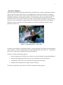
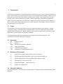
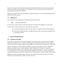
February 19, 2007
Lakshman One
Simon Fraser University
Burnaby, BC,V5A 1S6
RE: ENSC440 Functional Specification for Slalom Race Organizer
Dear Mr. One,
Enclosed please find our ENSC440 Functional Specification for Slalom Race Organizer.
Our objective is to list the functional specifications needed for our 440 project.
We are on our way designing and building an automated kayak race timing system
which can be installed on existing kayak race courses to eliminate the need for judges at
each gate. This device will also wireless transmit all of this data to the judges station,
providing a wealth of information for race timing and self-improvement purposes.
In the attached functional specification, we outline the parameters that the Slalom Race
Organizer will fulfill. Furthermore, this document will list the specifications for the
project deadline in April as we hope to have a production-quality version ready at this
time.
ImuTime Systems is comprised of four innovative and driven engineering students –
Ashley Penna, Chris Munshaw, Kevin Lockwood, and John So. Refer to Team
Organization and Company Profile section of our proposal to learn more about the
ImuTime Systems team.
If you have any questions or concerns regarding the attached document please feel free
contact us by email at [email protected]
Sincerely,
Kevin Lockwood
President & Project Manager
ImuTime Systems
Enclosed: Functional Specification for Slalom Race Organizer
Functional Specification for
Slalom Race Organizer
Project Team:
Kevin Lockwood
Chris Munshaw
John So
Ashley Penna
Contact Person:
Chris Munshaw
[email protected]
[email protected]
604-418-9127
Submitted to:
Steve Whitmore – ENSC 305
Lucky One – ENSC 440
School of Engineering Science
Simon Fraser University
Issued Date:
Revision:
February 19, 2007
1.1
1
Executive Summary
Whitewater kayak slalom racing began shortly before World War II as a branch of traditional whitewater
canoe racing. This Olympic sport involves racers paddling down a natural or man-made river through
hanging pairs of gates in a kayak, usually made of fiberglass or plastic. The racer must proceed through
green gates in the down-river direction (see Figure 1-1), and red gates in the up-river direction. The
overall time of the racer from start to finish is recorded, and time penalties are added for gates touched by
the racer as well as missed gates. A judge watches each set of gates from the shoreline, recording time
penalties for each racer that goes by. Human judging is an inefficient method that introduces a huge
potential for human error.
Figure 1-1: Slalom Kayak Racer – Source: IOC
Currently, each of the gates is individually manned. A judge determines if the kayaker passes through the
each set of gates, as well as determining the time at the beginning and the end of the race. Using humans
for this task is cumbersome, potentially inaccurate and expensive.
This device will have the following features:
1. Sensors mounted on each of the two sets of poles can tell if the kayaker has passed through them.
2. Sensors at the beginning and end of the race can tell when the race starts and finishes.
3. Accelerometer will be able to tell if kayaker has bumped either of the poles.
4. All data will be transmitted to the judge’s station for analysis.
This will be completed by April of 2007, and will be a production-ready prototype.
2
Table of Contents
Executive Summary ................................................................................................................................ 1
1
Introduction ..................................................................................................................................... 3
1.1
Scope....................................................................................................................................... 3
1.2
Acronyms ................................................................................................................................ 3
1.3
Referenced Documents............................................................................................................. 3
1.4
Intended Audience ................................................................................................................... 3
1.5
Objectives................................................................................................................................ 4
2
System Requirements ...................................................................................................................... 4
2.1
System Overview..................................................................................................................... 4
2.2
Physical Requirements ............................................................................................................. 5
2.2.1 General............................................................................................................................... 5
2.3
System Requirements............................................................................................................... 5
2.3.1 General............................................................................................................................... 5
3
4
5
6
7
2.3.2
Performance ....................................................................................................................... 6
2.3.3
Compatibility...................................................................................................................... 6
2.3.4
Reliability & Serviceability................................................................................................. 6
2.3.5
Regulations ........................................................................................................................ 6
Interface Requirements .................................................................................................................... 7
3.1
Main Menu .............................................................................................................................. 7
3.2
Start Recording ........................................................................................................................ 7
3.3
Save......................................................................................................................................... 8
3.4
Add/Remove/Change gate........................................................................................................ 8
3.5
Print......................................................................................................................................... 8
Wireless Network ............................................................................................................................ 8
Regulatory Requirements................................................................................................................. 8
Documentation & User Training ...................................................................................................... 9
Conclusion....................................................................................................................................... 9
List of Figures
Figure 1-1: Slalom Kayak Racer – Source: IOC....................................................................................... 1
Figure 2-1: Slalom Race Organizer .......................................................................................................... 5
3
1
Introduction
The Slalom Race Organizer is a system that will track information about a racer’s progression through the
course, and send this to the supervising official. This will be accomplished by mounting a module on each
of the poles on a kayak course that contains a microprocessor, actuator, sensor and necessary circuitry.
This data will be wireless transmitted to a central computer at the judge’s station that will graphically
display all relevant information. The Slalom Race Organizer will increase the accuracy and credibility of
the race results, while reducing the human error currently introduced. This product will be developed to a
production-ready level by April, 2007.
1.1 Scope
This functional specifications document describes the features that must be met to produce a working
system that functions as mentioned in the introduction above. A full set of functional requirements in
supplied for this prototype device. By the completion of this project we hope to have a working a system
that produces accurate solutions up to industry standards.
The requirements listed here are determined by the design of the Slalom Race Organizer. The
requirements are traceable in the design documents
1.2 Acronyms
ITS
IR
RoHS
LED
CPC
CTR
ImuTime Systems
Infrared
Restriction of Hazardous Substances
Light-emitting Diode
Central Personal Computer
Coordinator or Transmitting/Receiving
1.3 Referenced Documents
[1]
Proposal for the Slalom Race Organizer. ImuTime Systems.
[2]
Canoe/Kayak Slalom Racing Rules. http://www.whitewaterslalom.org
[3]
Spectrum Management and Telecommunications. Industry Canada.
[4]
Maxstream Inc. www.maxstream.net
[5]
Spark Fun Electronics. www.sparkfun.com
[6]
Digikey. www.digikey.com
1.4 Intended Audience
The design engineers on our team will use this document as a guideline when developing the Slalom Race
Organizer.
4
The project manager will use this document to determine the tasks, and to ensure that the group meets
performance and development landmarks. The manager will also use this document to ensure that all
design requirements have been achieved.
Marketing personnel will use this document for promotional material, as well as initial presentations and
publications of this solution.
1.5 Objectives
We will follow the convention below to denote functional requirements:
[R#]
A functional requirement
For the purpose of this document, and prioritizing for the developers and managers, we will use the
system below to indicate the priority of each functional requirement.
(1) A functional requirement that is mandatory for the acceptance into the kayaking industry.
(2) A functional requirement that is an additional feature that would ease the acceptability into
the kayaking industry.
2
System Requirements
2.1 System Overview
The kayak race organizer has four main components: the timing computer, network host, gate modules,
and start/end modules. Figure 2-1 shows a simplified model of the interactions that occur for a typical
slalom race setup. The timing computer is not included in our system but is any laptop or PC with a USB
interface. The software for the computer is included, and will provide functions such as ‘add/remove
gates from the network’, as well as providing a real time display to show the time intervals and
monitoring modules attributes. These attributes include ‘gate has been cleared’, ‘gate has been touched’,
etc. The network host is an external component that contains the RF transceiver used to communicate
with the other modules in the network. It also includes a USB connector. The start module will be treated
differently in that it will signal the start of the race time, and will not include the ‘gate touch’ attribute.
Similarly, the end module will signal the end of the race time.
5
river
start
module
gate
module
timing
computer
network
host
gate
module
end
module
Figure 2-1: Slalom Race Organizer
2.2 Physical Requirements
There are some important physical requirements associated with our system due to the environment in
which it will be used. Because of the limited access to external power around rivers, we must use an
internal power supply. This is an important factor in choosing a case for the gate and start/end modules, as
they must also be water and shock resistant.
2.2.1
General
R[1]
All modules including the network host are made to be water resistant. (1)
R[2]
All modules including the network host are made to operate normally under the temperature
range -40 to 85°C. (1)
R[3]
All modules including the network host include an internal power supply that a user of the system
may access easily. (2)
R[4]
The gate and start/end modules will provide enough cushioning as to prevent damage from
acceleration up to 2.0g. (1)
R[6]
The sensors on each gate module will not interfere with the racer’s clearance through the gates.
(1)
R[7]
Due to the nature of typical hanging gates, gate and start/end modules must not weigh in excess
of 5kg. (2)
R[8]
All modules must include a simple detachable form of mounting to a rigid gate design. (2)
2.3 System Requirements
2.3.1
General
6
R[9]
Software should be intuitive and easy to setup. (1)
R[10] User should be able to control gate operations remotely from CPC via CTR. (2)
R[11] Software and CTR should be adaptable to any number of modules present in the network. (1)
R[12] Modules should accurately detect the instant that the kayaker passes between the gates
completely (1)
R[13] Modules should detect any contact by kayaker on the gates. (1)
R[14] Network system should be able to handle and time multiple kayakers in the race course. (2)
R[15] Each module should be as inexpensive as possible, current aim is $200. (2)
2.3.2
Performance
R[16] Maximum radius for HiFi communication between a gate and the CTR is 1km (1)
R[17] Timing should be accurate to within +/-0.001 sec. (1)
R[18] Networking will be automated by CTR, with no user interaction necessary (2)
R[19] System automatically scans for the best frequency to communicate on (2)
R[20] Gate modules will provide a signal representing whether the gate has been touched by a racer,
and only a racer. (2)
R[21] Gate and start/end modules will provide a signal representing whether the gate has been cleared
by a racer (the racer has passed between the two gates) and only a racer. (1)
2.3.3
Compatibility
R[22] Software and USB interface between CTR and CPC should be compatible with all commonly
used laptops and PCs. (1)
R[23] Modules should be compact, lightweight and easily attachable to current gates used in kayak
racing. (2)
2.3.4
Reliability & Serviceability
R[24] Module’s internal power supply must be easily accessible to remove/recharge. (1)
R[25] Internal power supplies must have power life of at least six hrs under normal module operation.
(1)
R[26] Internal power supplies must be able to be remotely monitored from the CPC. (2)
R[27] Modules should have the ability to remotely shut off. (2)
R[28] Each module will have power conservation modes when not detecting or transmitting. (2)
R[29] Modules not serviceable by end users, except to removal/recharge of internal power supply. (2)
2.3.5
Regulations
7
R[30] For use in Japan, limits must exist in firmware to ensure transmission power must not exceed
10dBm. (2)
R[31] For use in Japan, modules must contain a clearly visible label of the following text:
ID: 005NYCA0378 (2)
R[32] For use in Canada, modules must contain a clearly visible label of the following text:
Contains Model XBee-PRO Radio, IC: 4214A-XBEEPRO (1)
R[33] For use in Europe, modules must conform to the European harmonized EMC and lowvoltage/safety standards. (2)
R[34] For use in Europe, limits must exist in firmware to ensure transmission power must not exceed
10dBm. (2)
R[35] For use in Europe, modules must contain a clearly visible label of the following. (2)
3
Interface Requirements
Requirements listed for the user interface defined below are in terms of the screens displayed on the
judge’s computer and the buttons he/she can press.
3.1 Main Menu
From the main menu the user can navigate options regarding timing of the race. There will be four main
options:
R[36] Start recording times. (1)
R[37] Save recorded times. (1)
R[38] Add/Remove/Change gates. (1)
R[39] Print recorded times. (2)
3.2 Start Recording
This is the recoding menu that will display the racing results as the kayaker passes though the course.
R[40] The system will begin recording. (1)
R[41] The start time will be recorded. (1)
R[42] The split time as the user passes through each of the gates will be recorded. (2)
R[43] The stop time will be recorded. (1)
R[44] If the kayaker touches any of the gates, this will be noted. (1)
R[45] There will be a button on this screen that returns to the previous menu saving all information that
has been recorded so far before the button has been pressed. (1)
8
3.3 Save
This screen will allow the user to save race information.
R[46] This will allow the user to either save the recorded information or discard it. (1)
3.4 Add/Remove/Change gate
This will allow the user to add gates, remove gate, and change the order of the gates in the system. This
will let the user see the results of each gate in the order that they happen.
R[47] The user will be able to add gates (modules) to the system. (1)
R[48] The user will be able to delete gates (modules) from the system. (1)
R[49] The user will be able to change the gate number of each gate that has been added to the system.
(1)
3.5 Print
This will allow the user to print race result information.
R[50] The user will be able to print using their usual printer settings. This will print the results in a userfriendly form. (1)
4
Wireless Network
These requirements define the type, range, rate, and other features of communication between a gate and
the main computer.
R[51] Minimum transmission range of 1km. (1)
R[52] Transceiver needs to be powered by batteries with voltage between 2.8V to 3.4V. (1)
R[53] Batteries need to be easily bought and replaced, for a reasonable price. (2)
R[54] Transceiver needs to operate continuously for minimum of 4 hours with new batteries. (1)
R[55] Minimum transmission data rate of 10000bps. (1)
R[56] Minimum 18 communication channels, to be chosen after fidelity scans. (2)
R[57] The user will be able to switch transceiver at gate to or from sleep mode through the user
interface. (2)
5
Regulatory Requirements
The Race Organizer system is subject to the following government regulations.
R[58] Transceivers will be approved by FCC (U.S.A), IC (Canada), and ETSI (Europe). (1)
R[59] Transceivers will follow ICES-001 and SRSP and respect the frequency spectrum allocation in
Canada. (1)
9
R[60] Materials used in the product will satisfy RoHS. (1)
R[61] The module will be protected by waterproof materials. All electrical connection will be enclosed
and yield no danger to the user. (1)
Note that the user is expected to handle the Race Organizer system with care. ImuTime also cautions that
users should avoid exerting excessive force on the module, and never allow the sensors and transceivers
be lowered under water, or swallowed by children.
6
Documentation & User Training
Since most users of the product are kayak race organizers, who are not necessarily technically proficient
and familiar with the user interface, the following requirements have been set for documentation and user
training.
R[62] Documentation of this product will consist of a forty page user manual with instructions in
English and French. (1)
R[63] The user manual will be written for audiences with no experience of electrical devices and
minimal experience of computer usage. It will include instructions for basic operations. (1)
R[64] A section of user manual will be devoted for more advanced features that target experienced
users. (2)
R[65] The user manual will include a device characteristics list and a troubleshooting section. (2)
R[66] User training will be provided as a section of the user manual. (2)
7
Conclusion
We feel that the requirements in this document are both strict yet flexible enough to allow for a smooth
transition into the sport of whitewater kayaking. Our goal is not to change the dynamics of the sport, but
to enhance it using the latest technologies available. This document does not require any part of our
system to break the traditional layout of a slalom race, and it is written such that we can upgrade our
system to use more accurate and cost-effective technologies at any point in time without changing the
requirements. This aspect was important to us, as we expect to come across unforeseen obstacles while
building and testing prototypes, but have defined our project such that a solution will never require
changing our functional specifications.