1
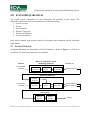
School of Engineering Science Simon Fraser University Burnaby, BC V5A 1S6 [email protected] October 16, 2009 Dr. John Bird School of Engineering Science Simon Fraser University Burnaby, British Columbia V5A 1S6 Re: ENSC 440 Functional Specifications for an Ecological Monitoring System Dear Dr. Bird: Attached is a document outlining the functional specifications of our proposed ecological monitoring system, the ECOmonitor. Our project entails the monitoring of environmental conditions (CO2 levels, temperature etc.) in remote areas using a wireless data „hopping‟ technology. This document outlines the required functional specifications for the proof-of-concept design of the ECOmonitor, as well as, additional requirements for the final production. The project manager will use this document to monitor completion of goals and manage scheduling. The team members will use the requirements as goals during the product design phase and as a guideline for functionality testing. The ECOmonitoring Technologies Inc. team consists of five innovative and passionate engineers: Ryan Cimoszko, Amandeep Grewal, Brian Lee, Kianoush Nesvaderani and myself, Harvir Mann. If you have any questions or concerns about our functional specifications, please feel free to contact me by e-mail at [email protected]. Sincerely, Harvir Mann President and CEO ECOmonitoring Technologies Inc. Enclosure: Functional Specifications for an Ecological Monitoring System FUNCTIONAL SPECIFICATIONS FOR AN ECOLOGICAL MONITORING SYSTEM Project Team: Ryan Cimoszko Amandeep Grewal Brian Lee Harvir Mann Kianoush Nesvaderani Contact Person: Harvir Mann [email protected] Submitted to: Dr. John Bird – ENSC 440 Steve Whitmore – ENSC 305 School of Engineering Science Issue Date: October 19, 2009 Revision: 1.1 Functional Specifications for an Ecological Monitoring System EXECUTIVE SUMMARY With issues surrounding global warming and climate change being of greater importance, the ability to monitor and detect abnormal environmental conditions are needed now more than ever. The increase in overall temperature has been regarded as the cause for the California wildfires this past summer which has burned over 336,000 acres of land, destroyed hundreds of homes and have taken many lives [1, 2]. The ECOmonitor is a wireless real-time environmental monitoring system designed to detect abnormal environmental behavior and can be used to prevent situations such as the California wildfires from happening again. The ECOmonitor will be developed in two phases: proof-of-concept and final production. The proof-of-concept phase will include: Two monitoring stations which collect data on CO 2 levels, temperature and humidity. Wireless data „hopping‟ network to relay the data to the database. An online database for storing of the data. A webpage to view the data numerically and graphically. The functional requirements for each component have been identified and will be used by the ECOmonitoring Technologies Inc. team as a guideline for design and functionality testing. The target completion date for the proof-of-concept design is December 1, 2009. The final production model will include additional features that will assure reliability and functionality under various weather conditions, flexibility for monitoring various environmental conditions and the ability to monitor a full-scale area. ECOmonitoring Technologies Inc. ii | P a g e Functional Specifications for an Ecological Monitoring System TABLE OF CONTENTS Executive Summary............................................................................................................................ii List of Figures ...................................................................................................................................iv 1.0 Introduction................................................................................................................................ 1 1.1 Scope .......................................................................................................................................... 1 1.2 Intended Audience ...................................................................................................................... 1 1.3 Classification .............................................................................................................................. 1 2.0 System Requirements ............................................................................................................... 2 2.1 System Overview ........................................................................................................................ 2 Physical Requirements ........................................................................................................... 3 Electrical Requirements ......................................................................................................... 3 Performance and Reliability Requirements ............................................................................. 3 Reliability .............................................................................................................................. 3 Usability Requirements .......................................................................................................... 3 Standards ............................................................................................................................... 3 Luxury Functions ................................................................................................................... 3 2.2 Sensors ....................................................................................................................................... 4 General Requirements ............................................................................................................ 4 Physical Requirements ........................................................................................................... 4 Electrical Requirements ......................................................................................................... 4 Operating Conditions ............................................................................................................. 4 Reliability and Durability ....................................................................................................... 4 2.3 Microcontroller ........................................................................................................................... 5 General Requirements ............................................................................................................ 5 Electrical Requirements ......................................................................................................... 5 Physical Requirements ........................................................................................................... 5 Microcontroller Requirements................................................................................................ 5 Usability Requirements .......................................................................................................... 6 2.4 Wireless Transceiver ................................................................................................................... 6 General Requirements ............................................................................................................ 6 Physical Requirements ........................................................................................................... 6 Electrical Requirements ......................................................................................................... 6 Wireless Signal Requirements ................................................................................................ 7 Operating Conditions ............................................................................................................. 7 Reliability and Durability ....................................................................................................... 7 2.5 Database and Webpage Interface................................................................................................. 7 General Requirements ............................................................................................................ 7 Software/Technical Requirements .......................................................................................... 8 2.6 User Documentation ................................................................................................................... 8 3.0 System Test Plan ........................................................................................................................ 9 3.1 Phase 1 – Individual Parts ........................................................................................................... 9 3.2 Phase 2 – Individual Units......................................................................................................... 10 3.3 Phase 3 – Complete System ...................................................................................................... 10 4.0 Conclusion ................................................................................................................................ 11 5.0 References ................................................................................................................................. 12 ECOmonitoring Technologies Inc. iii | P a g e Functional Specifications for an Ecological Monitoring System LIST OF FIGURES Figure 1: System Overview .................................................................................................................. 2 GLOSSARY ADC Analog-to-Digital Converter ANSI American National Standards Institute CSA Canadian Standards Association DC Direct Current FCC Federal Communication Commission FRC Frame Redundancy Check GND Ground HTML Hyper Text Markup Language LED Light-Emitting Diode PC Personal Computer PHP PHP: Hypertext Preprocessor RoHS Restriction of Hazardous Substances UART Universal Asynchronous Receiver Transmitter USB Universal Serial Bus VCC Common-collector voltage ECOmonitoring Technologies Inc. iv | P a g e Functional Specifications for an Ecological Monitoring System 1.0 INTRODUCTION The ECOmonitor entails the construction of a sensor network that gathers data on certain environmental characteristics and communicates with a base station via a signal „hopping‟ scheme. The data will be collected at each monitoring station and will be wirelessly relayed to the next monitoring station that is closest to the base station. Finally the data is sent back to the base station at which point the data will be analyzed and placed online. The proposed functional specification requirements for the ECOmonitor are described in this document. 1.1 SCOPE The requirements needed for a proof-of-concept design of the ECOmonitor, as well as, additional requirements for the final production are described in this document. These requirements are needed to properly assess design goals and ensure that the ECOmonitor‟s functionality is aligned with our target market‟s usability goals. 1.2 INTENDED AUDIENCE The intended audience for the functional specifications are the members of the ECOmonitoring Technologies Inc. team. This document will be used as a guideline for the project manager to observe completion of goals, organize scheduling and assess the level of effort needed. The team members will use to requirements as goals for the product design as well as a guideline for functionality testing. 1.3 CLASSIFICATION In order to identify and categorize each functional requirement, the following convention is used: R[X-Y] The Functional Requirement. The „X‟ denotes the number of the functional requirement for future referencing and the „Y‟ specifies the requirement category which falls into one of the following two: I – Requirement present in the proof-of-concept and final production. II – Requirement present in the final production only. ECOmonitoring Technologies Inc. 1|Page Functional Specifications for an Ecological Monitoring System 2.0 SYSTEM REQUIREMENTS The overall system requirements for the ECOmonitor are presented in this section. The functional requirements have been divided into the following sections: 1. System Overview 2. Sensors 3. Microcontroller 4. Wireless Transceiver 5. Website and Database 6. User Documentation Each section contains some general, physical, performance and component specific functional requirements. 2.1 SYSTEM OVERVIEW A diagram illustrating the functionality of the ECOmonitor is shown in Figure 1 as well as an overall list of system requirements has been outlined. Figure 1: System Overview Environmental Conditions OUTPUTS Monitoring Station #1 INPUTS Signal Processing Data Buffer Wireless Transmitter Measured Data #1 Monitoring Station #2 Wireless Receiver Environmental Conditions Signal Processing Data Buffer Wireless Transmitter Measured Data #1 Measured Data #2 Base Station Wireless Receiver ECOmonitoring Technologies Inc. Database Storage Webpage 2|Page Functional Specifications for an Ecological Monitoring System Physical Requirements R[1-I] The monitoring stations shall be no larger than 300 mm width, 250 mm depth and 120 mm height. Electrical Requirements R[2-I] The monitoring stations shall consume minimal power in order to maintain operation for a lengthy period of time. Performance and Reliability Requirements R[3-II] R[4-II] The system shall be highly accurate with a maximum error of 2 %. The system shall be able to monitor a large area. Reliability R[5-I] R[6-II] The monitoring stations shall be durable and weather resistant. The monitoring stations shall be reliable under all weather conditions. Usability Requirements R[7-I] The system shall be easy and simple to restart. Standards R[8-II] R[9-II] The system shall comply with ANSI and CSA standards. The system shall comply with FCC regulations. Luxury Functions R[10-II] R[11-II] R[12-II] R[13-II] The monitoring stations shall have the ability to add or remove sensors through USB port with minimal re-programming. The monitoring stations shall be powered by solar energy. The webpage interface shall provide the user the ability to turn the monitoring station on and off. The system shall have dynamic wireless „hopping‟ network in case monitoring stations malfunction. ECOmonitoring Technologies Inc. 3|Page Functional Specifications for an Ecological Monitoring System 2.2 SENSORS The primary function of the sensors will be to detect changes of an environmental condition, which will vary with application, and to notify the system the level of reading. Our system is adaptable to many different types of application so the user is free to choose which sensors they would like to have implemented. For our project we will be using the system for wildfire detection so we will use sensors applicable for fire detection. We will be detecting parameters which are found in fires or in fire hot spots. Hot spots usually have a combination of the following: Abnormal CO2 levels Increased humidity levels High temperatures So by monitoring all three of these factors we will be able to detect a wild fire or monitor hot spots which can be in danger. By sensing three parameters our system will be able to minimize false alarms. General Requirements R[14-II] R[15-I] The sensors shall be waterproof. The sensors shall take a reading at least every one minute. Physical Requirements R[16-I] The sensors shall be as small as possible, preferably under 30 mm by 30 mm, to minimize overall size of unit. Electrical Requirements R[17-I] Each sensor shall consume less than 50mW of power. Operating Conditions R[18-II] R[19-II] The sensors shall be able to withstand and work properly under various weather conditions (i.e. rain, snow, hail). The sensors shall be able to operate at temperature levels between -40 and 100 degree Celsius. Reliability and Durability R[20-II] R[21-II] The sensors must give readings with a maximum error of 2%. The sensors shall have an operational lifespan of at least 5 years. ECOmonitoring Technologies Inc. 4|Page Functional Specifications for an Ecological Monitoring System 2.3 MICROCONTROLLER The microcontroller module has two main purposes. One is the „hopping‟ mechanism: processing the data packets received by wireless transceiver and re-packing it combining all the subsequent data packets as well as the newly received data packets. Then the re-packed data is sent to another sensor point through wireless transceiver again. The other purpose is to communicate with the host PC. The data packet that contains all sensor points' data is sent to the host PC via UART. General Requirements R[22-I] R[23-I] R[24-I] R[25-I] The microcontroller modules shall have Reset and Power buttons. The microcontroller modules shall have proper LED indicators for Reset, Power, and Alert signals. The microcontroller modules shall be powered by power adaptors. Resolution of ADC shall be no less than 10-bits. Electrical Requirements R[26-I] R[27-I] R[28-I] R[29-II] The microcontroller modules shall be powered by 6V~20V and at least 500 mA power adaptors. The microcontroller modules‟ output power shall not be more than 6 W. Power dissipations of each component on the microcontroller modules shall not exceed 80% of their power ratings. The microcontroller modules shall follow the standard RoHS requirements. Physical Requirements R[30-I] R[31-I] R[32-I] Dimension of the microcontroller modules shall be no more than 160 mm length by 110 mm width by 50 mm height. The weight of a microcontroller module shall be no more than 0.5 kg. The shape of the modules shall be rectangular in order to easily fit into a box where the module can be protected from various weather conditions. Microcontroller Requirements R[33-I] R[34-I] R[35-I] The coding space shall not be more than 80 % full in order to account for further upgrades in the future. Only maximum of 80 % of the input/output pins shall be used in order to account for further upgrades in the future. The programming languages used shall primarily consist of well-known languages such as C/Python. ECOmonitoring Technologies Inc. 5|Page Functional Specifications for an Ecological Monitoring System R[36-I] R[37-I] R[38-I] Communication protocols shall primarily consist of standard 2-wire interface (I2C/SMBus) protocols with the latest version as possible. The microcontroller modules shall be connected to other modules by means of standard 10 pin FRC connector and 10 pin male header (including VCC and GND). The microcontroller modules shall be connected to the PC by means of USB Port UART Links and USB ISP Programmer. Usability Requirements R[39-I] R[40-I] The microcontrollers shall be capable of easy debugging. The upgrades of microcontroller shall be able to be done easily. 2.4 WIRELESS TRANSCEIVER The wireless transceivers primary purpose is to facilitate the sending and receiving of information gathered from the sensors to the base station. Key parameters that must be considered for the wireless transceiver are signal range, transmission rate, and power consumption. General Requirements R[41-II] R[42-I] R[43-II] R[44-II] R[45-I] The transceiver shall be able to transmit information to a range of 0.3 m. The transceiver shall be able to receive a signal and repeat that signal to the next transceiver in the sensor chain, or base station if it is the last receiver in the sensor chain. The transceiver shall be able to simultaneously transmit data to multiple receivers. The transceiver shall be able to distinguish between different transmitters when receiving data. Base station receiver shall be able to connect via USB to a PC. Physical Requirements R[46-I] Wireless transceiver and antenna shall fit within the weather resistant sensor box. Electrical Requirements R[47-I] R[48-II] R[49-II] The wireless transceiver shall work with a 3.0V~3.6V DC power supply. The wireless transceiver shall operate in the presence of other sources of interference. The wireless transceiver shall follow the standard RoHS requirements. ECOmonitoring Technologies Inc. 6|Page Functional Specifications for an Ecological Monitoring System Wireless Signal Requirements R[50-I] R[51-I] R[52-I] R[53-II] R[54-I] R[55-II] In compliance with FCC regulations concerning industrial/commercial wireless transmission the wireless transceiver shall transmit/receive at 900 MHz frequency.[3] The wireless transceiver shall not interfere with internal electrical components of the ECOmonitor. The wireless transceiver shall not interfere with any external electronic equipment. The wireless transceiver shall not interfere with any frequencies used by park rangers/search and rescue personnel. The wireless transceiver shall minimize co-channel interference. The signal will have a bandwidth that complies with FCC regulations. Operating Conditions R[56-II] The wireless transceiver shall operate reliably in the -40°C to + 50 °C temperature range. Reliability and Durability R[57-I] R[58-I] The wireless transceiver shall have a maximum of 1% packet transmission loss. The wireless communication network shall employ signal redundancy to minimize the effect of losing a sensor station/repeater station. 2.5 DATABASE AND WEBPAGE INTERFACE The main purpose of the webpage is to present the data received from the sensors, in both numerical and graphical ways. The purpose of the database is to store the data first before having them posted online. The data will first be transferred from the microcontroller via USB to a PC and stored. Then, the website will be updated based on the data stored in the database. General Requirements R[59-I] R[60-I] R[61-I] R[62-I] R[63-I] R[64-II] The webpage shall be user-friendly. The webpage shall be refreshed automatically every one minute. The webpage shall show data readings both numerically and graphically. The webpage shall show the time at which the data was collected. The webpage shall show an average value of the collected data. The database shall be highly secured when online (Only readable for the users). ECOmonitoring Technologies Inc. 7|Page Functional Specifications for an Ecological Monitoring System Software/Technical Requirements R[65-I] R[66-I] R[67-I] R[68-II] The webpage and database shall be hosted by an online server. The webpage shall be designed in HTML. The database shall be written in PHP. The database shall be designed so that minimal re-programming will be needed when adding or removing sensors. 2.6 USER DOCUMENTATION R[69-II] R[70-II] R[71-II] Technical support including a user manual and installation guide will be available online through the company webpage. The user manual and installation will be written for an audience with minimal knowledge of wireless data transmission, webpage broadcasting and data collection electronics. User manual and installation guide will be written in the primary language of where the product is sold. ECOmonitoring Technologies Inc. 8|Page Functional Specifications for an Ecological Monitoring System 3.0 SYSTEM TEST PLAN To ensure full functionality, we will thoroughly test and verify each component of the ECOmonitor. Our proposed system test plan consists of a three phase process: 1. Testing each individual part (sensors, wireless transceiver, micro-controller, website and database) 2. Testing each component (monitoring station and base station) 3. Complete integration 3.1 PHASE 1 – INDIVIDUAL PARTS Sensors We will first test each sensor individually to ensure that they work properly and give an accurate reading. We will first perform the test at standard room conditions and then under various conditions (i.e. higher CO2 levels, higher temperature). After it has been verified that all of the individual sensors work correctly, we will combine all of the sensors and perform similar tests. In addition, we will measure the power dissipated by the sensors to ensure that it is within the limit outlined in the sensor requirements. Wireless Transmission For the wireless transmitter/receiver pair we will be testing if the transmitter is able to send a signal to the receiver and that the receiver receives the correct signal. We will vary the distance between the receiver and the transmitter to verify that long range communication is possible. Next, we will add in a second transmitter through which the signal can be relayed back to the receiver. Since our system will consist of relaying signals from the sensors to the receiver, it will be essential that this type of communication topology works correctly. Microcontroller The proper functionality of the microcontroller will be tested here. We will verify that the micro-controller is able to take in a digital input signal and output the appropriate signal. Website & Database Here we will be testing the proper functionality of our database and company website. Communication between the database and website will be tested here also to make sure that the website is automatically updated every one minute with the new data that has been input into the database. In addition we will be testing that the online plots of the sensor readings are updat ed with each subsequent sensor reading, and match the data being collected by the sensors. ECOmonitoring Technologies Inc. 9|Page Functional Specifications for an Ecological Monitoring System 3.2 PHASE 2 – INDIVIDUAL UNITS We will be combining the individual parts in phase one and creating two subsystems which will be called the monitoring stations and base station. The monitoring station will consist of the microcontroller, sensors and a wireless transceiver. Here we will be testing if the microcontroller is able to interpret the input signal, reading from the sensors, and output the correct binary signal to send back to receiver via the wireless transmitter. We will also measure the total power dissipated by the unit to ensure that it is less than 5 W. This is important because in order to implement solar panels to power the monitoring stations power rating of 5 W must be used. The base stations will include a wireless receiver, data storage and the webpage component. Here we will be testing to see if we can receive data, store it correctly and display that data on the webpage. 3.3 PHASE 3 – COMPLETE SYSTEM We will be testing the functionality of the complete ECOmonitor for this phase. The system will consist of two monitoring stations, a base station and a custom webpage component. For this testing we will place the monitoring stations100 meters apart from each other and 500 meters away from the base station. To mimic a wild fire, we will start a small controlled fire near the monitoring station farthest away from the receiver or use other means which will allow us to vary humidity, temperature and CO2 levels. We will closely monitor the system to ensure that it is able to detect the fire and relay the sensor readings to the base station, via the wireless transmitter in the monitoring station. Then we will check that these readings get stored in the database and updated on the website. ECOmonitoring Technologies Inc. 10 | P a g e Functional Specifications for an Ecological Monitoring System 4.0 CONCLUSION The functional specifications for the proof-of-concept and final production of the ECOmonitor have been outlined in this document. The proposed test plan consists of three phases which include testing of individual parts, then individual units and finally the complete system. We are currently in phase one, testing of individual parts, and we are confident that the functional requirements for the proof-of-concept, labeled R[X-I], will be completed by the proposed date of December 1, 2009. ECOmonitoring Technologies Inc. 11 | P a g e Functional Specifications for an Ecological Monitoring System 5.0 REFERENCES [1] D. Shapely, “California Wildfires and Global Warming,” October 23, 2007, http://www.thedailygreen.com/environmental-news/latest/Global-Warming-CaliforniaWildfire-47102305. [2] Wikipedia, “2009 California Wildfires,” October 10, 2009, http://en.wikipedia.org/wiki/2009_California_wildfires [3] Federal Communication Commission, “Industrial/Business,” March 24, 2008,http://wireless.fcc.gov/services/index.htm?job=service_home&id=industrial_business ECOmonitoring Technologies Inc. 12 | P a g e