1
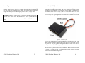
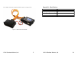
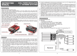
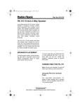
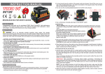
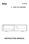
Rev 1.00
SK-PW7 User Manual & Setup Guide
SK-PW7
Servo
Power Bus
User Manual and Setup Guide
Table of Contents
1
Introduction ...........................................................................3
2
Package Contents.................................................................4
3
Safety .....................................................................................5
4
Principle of Operation ..........................................................6
5
Power Connections ..............................................................7
6
Servo Connections .............................................................10
Appendix A: Specifications ......................................................14
Appendix B: Warranty ...............................................................15
Conveniently connect high or standard voltage
servos to your SK720 using the light and compact
SK-PW7 power bus. Rated for a 20-Amp capacity,
this power bus will eliminate brown-outs and
simplify wiring aboard your medium to large size
R/C helicopter.
©2010 Skookum Robotics, Ltd
2
1
Introduction
2
The SK-PW7 servo power bus is a compact and light solution for your servo
wiring needs. Intended for use on medium and large size radio controlled
helicopters; it allows connection of an SK720 digital flybar to your high voltage
(8.4-Volt, typical) servos. The rated 20-Amp capacity will also help eliminate
brownouts. And the power bus even offers the flexibility to use a combination of
high and standard voltage servos on your radio-controlled helicopter, while
maintaining a tidy wiring installation.
©2010 Skookum Robotics, Ltd
3
Package Contents
Your servo power bus package includes:
•
•
SK-PW7 Servo Power Bus
Four servo cable jumpers
©2010 Skookum Robotics, Ltd
4
3
Safety
4
The SK-PW7 servo power bus does not include a switch, fuse or voltage
regulator. Install switches, fuses and / or a BEC (as required for your installation)
into your circuit per standard practices. Ideally, check all electrical connections
using a multi-meter prior to connecting the power bus to any voltage source.
WARNING: The Term “High Voltage” is used in this manual to differentiate
8.4-Volt servo systems from the standard 5-Volt servo systems. Do not
connect the SK-PW7 servo power bus to any supply voltage higher than 10
Volts.
Principle of Operation
The SK-PW7 servo power bus allows high and / or standard voltage servos to be
connected to your SK720 digital flybar. The device contains two separate “power
rails” that may be connected to a 5 Volt supply (such as a BEC or standard 4-cell
NiCd battery) or an 8.4-Volt supply (such as a 2-cell LiPo battery). The two
power rails can also be connected to one another if the entire system will be
powered at the same voltage. Note that the ground rail is common between both
the low voltage and high voltage sides.
Figure 4.1 – SK-PW7 Layout
Up to 9 servo channels can be connected through the SK-PW7 power bus. The
signals from the SK720 are output on the 3rd row (top row) of pins on the front of
the power bus. The pins on Bus-A through Bus-D on the back of the unit are
directly connected to the 3rd row (top row) of pins on the front face.
The power bus can also be used to power your SK720. When properly connected,
the SK720 will be powered off the PWR-HV power rail. The SK720 is rated for
up to 10V, so a single 8.4-Volt, 2-Cell LiPo battery will be sufficient to power
both your SK720 and high voltage servos.
©2010 Skookum Robotics, Ltd
5
©2010 Skookum Robotics, Ltd
6
5
Power Connections
The SK-PW7 has sockets for servo plugs on the front and back face. The back
face also comes fitted with two 18-gauge silicone wires. These wires supply the
high voltage bus when connected to a 2-cell, 8.4-Volt LiPo battery. A schematic
of the SK-PW7 box top is shown in the figure below.
The PWR-HV rail is powered directly by the two 18-gauge silicone wires fitted
to the back of the unit. The PWR-LV rail is not powered unless it is connected
to a voltage source such as a battery or BEC. The schematic in Figure 5.2 below
illustrates a typical BEC installation.
Figure 5.2 – Typical BEC Connection
The BEC may be supplied with 8.4-Volts from the socket labeled “BEC’s HV
Input” in the schematic above. The 5-Volt output of the BEC should then be
connected to the socket labelled “BEC’s LV OUTPUT”. Alternatively, the PWRLV rail could be powered by a 4-Cell NiCd battery connected to the socket
labelled “BEC’s LV Output”.
Figure 5.1 – SK-PW7 Layout
There are two power rails on the front face of the bus. The high voltage
(8.4-Volt) rail is labelled PWR-HV while the low voltage (5-Volt) rail is
identified as PWR-LV. The two labels are highlighted in orange in the schematic
above. Note that the SK-PW7 servo power bus does not include a switch, fuse or
voltage regulator. These must be installed separately, as required for your
installation. The sockets on the high and low voltage rails are labelled according
to their servo channel. The servo channels correspond to the SK720 outputs.
©2010 Skookum Robotics, Ltd
7
©2010 Skookum Robotics, Ltd
8
The PWR-LV rail can also be used as an 8.4-Volt rail by installing a jumper
between the PWR-LV and PWR-HV rails. To connect the two power rails,
connect the middle pins on the front face with a heavy-duty jumper as shown in
the images below. The ground rails are common between the two busses, so no
jumper is required across the lower row of pins.
6
Servo Connections
The front face of the SK-PW7 power bus is open and has 12 sockets for servo
plugs. Ten of these sockets are for connecting servos and are labelled according
to their corresponding SK720 channel. Note that there are only 9 channels
however, because the label “Tail” is present on both the PWR-HV and PWR-LV
busses. This allows the flexibility to power your tail servo from either the 8.4Volt bus or the 5-Volt bus, depending on your tail servo’s specifications.
Figure 6.1 – SK-PW7 Front Face Servo Connections
The nine servo channels on the high and low voltage busses are connected to the
SK720 via the 4 signal busses on the back face of the SK-PW7. The back face of
the SK-PW7 is shown in the Figure 6.2 image on the next page. The two 18gauge silicone power wires are also shown in the image.
Figure 5.3 – PWR-HV to PWR-LV Jumper Configuration
©2010 Skookum Robotics, Ltd
9
©2010 Skookum Robotics, Ltd
10
Figure 6.3 – SK-PW7 Signal Bus Connections Schematic
Connect the wires from the SK-PW7 signal busses to the SK720 so that the wires
from each of the channels shown in Figure 6.3 plug in to the corresponding pin
on the SK720. Note that the wires from signal BUS-B and signal BUS-C should
be connected across the top row of pins on the SK720 as shown in the Figure 6.4
photo. Again, if you’re not using satellite receivers, do not connect jumpers to
BUS-C or BUS-D.
Figure 6.2 – SK-PW7 Signal Bus Connections
Unlike regular servo wires, the four servo wires connected to the signal busses do
not all carry power; only the red and black (or orange and brown) wires on BUSA carry power to the SK720. The remaining wires just carry the signals from the
SK720 to the SK-PW7 power bus. The details are illustrated in Figure 6.3 on the
following page.
NOTE: If you are using a traditional receiver with your SK720 (i.e. you’re
not using satellite receivers), then servo ports IO-A through IO-D are not
available. In that case, only connect jumpers BUS-A and BUS-B. You will
then need to connect jumpers from the SK720’s ports IO-A Ext-LED to your
receiver, as described in the SK720 User Manual.
Figure 6.4 – SK720 Connections to SK-PW7
©2010 Skookum Robotics, Ltd
11
©2010 Skookum Robotics, Ltd
12
The completed assembly should look like the Figure 6.5 image, below.
Appendix A: Specifications
Dimensions
Weight (without cables)
Operating Temperature Range
Operating Voltage
Maximum Power Rating
39mm x 24mm x 15mm
16 grams
-10°C to +45°C
3.6 to 10 VDC
20 Amp
Figure 6.5 – SK720 Connections to SK-PW7
©2010 Skookum Robotics, Ltd
13
©2010 Skookum Robotics, Ltd
14
Appendix B: Warranty
Warranty and Repair:
Skookum Robotics Ltd warrants this product against any defects in materials or
workmanship for a period of 90 days from the purchase date. This warranty is
limited to the original purchaser. In the event of a malfunction, Skookum
Robotics will repair or replace the product to meet its standard operating
condition. This warranty does not apply in cases where the product has been
overheated, electrically shorted, subject to crash damage, otherwise abused, or
had unauthorized repair attempts.
UNDER NO CIRCUMSTANCES DOES SKOOKUM ROBOTICS ACCEPT
LIABILITY FOR INCIDENTAL DAMAGE OR INJURIES RESULTING
FROM THE OPERATION OF THE SK-PW7 POWER BUS OR OTHER
PRODUCTS.
Skookum Robotics will provide customers with technical assistance by email free
of charge. If a unit’s serviceability is in question following a crash, we will check
it over for only the cost of postage. If the unit has malfunctioned and the 90-day
warranty period has expired, we will attempt repair and discuss the cost of
possible repairs with the owner, again for only the cost of postage.
If you wish to return the SK-PW7 power bus, please write “WARRANTY
RETURN” clearly on the shipping box and mail it to the address given below.
Manufactured in Canada by Skookum Robotics, Ltd
Email:
Website:
[email protected]
www.skookumrobotics.com
Return Mail:
PO Box 46912 Stn D
Vancouver, BC
V6J 5M4 Canada
©2010 Skookum Robotics, Ltd
15