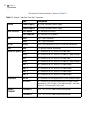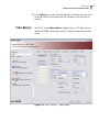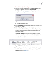
1
Hardware Installation and User Guide Nexio AMP® Compact Shared Storage Server (NXVOLT1401HDX) April 2014 175-000141-01 Delivering the Moment Publication Information © 2014 Imagine Communications Corp. Proprietary and Confidential. Imagine Communications considers this document and its contents to be proprietary and confidential. Except for making a reasonable number of copies for your own internal use, you may not reproduce this publication, or any part thereof, in any form, by any method, for any purpose, or in any language other than English without the written consent of Imagine Communications. All others uses are illegal. This publication is designed to assist in the use of the product as it exists on the date of publication of this manual, and may not reflect the product at the current time or an unknown time in the future. This publication does not in any way warrant description accuracy or guarantee the use for the product to which it refers. Imagine Communications reserves the right, without notice to make such changes in equipment, design, specifications, components, or documentation as progress may warrant to improve the performance of the product. Trademarks 6800+™, ADC™, CCS Navigator™, Channel ONE™, ChannelView™, ClipSync™, Delay™, D-Series™, D-Series DSX™, Deliver the Moment™, Delivering the Moment™, FAME™, Farad™, G8™, G-Scribe™, HView™, IconMaster™, IconLogo™, IconStation™, IconKey™, InfoCaster™, InfoCaster Creator™, InfoCaster Manager™, InfoCaster Player™, InstantOnline™, Invenio®, Live-Update™, mCAPTURE™, Magellan™, Magellan CCS Navigator™, Magellan Q-SEE™, MultiService SDN™, NetPlus™, NetVX™, NewsForce™, Nexio® G8™, Nexio AMP® ChannelView™, Nexio® Channel ONE™, Nexio® ClipSync™, Nexio® Delay™, Nexio® Digital Turnaround Processor™, Nexio® Farad™, Nexio® GScribe™, Nexio® IconKey™, Nexio® IconLogo™, Nexio® IconMaster™, Nexio® IconStation™, Nexio® InfoCaster™, Nexio® InfoCaster Creator™, Nexio® InfoCaster Manager™, Nexio® InfoCaster Player™, Nexio® InfoCaster Traffic™, Nexio® InstantOnline™, Nexio® mCAPTURE™, Nexio® NewsForce™, Nexio® NXIQ™, Nexio® Playlist™, Nexio® Remote™, Nexio®RTX Net™, Nexio® TitleMotion™, Nexio® TitleOne™, Nexio® Velocity ESX™, Nexio® Velocity PRX™, Nexio® Velocity XNG™, Nexio® Volt™, OPTO+™, Panacea™, Platinum™, Playlist™, Predator II-GRF™, Predator II-GX™, Punctuate™, Remote™, RTX Net™, QuiC™, Q-SEE™, SD-STAR™, Selenio™, Selenio 6800+™, SelenioNext™, Selenio X50™, Selenio X85™, Selenio X100™, TitleMotion™, TitleOne™, Velocity ESX™, Velocity PRX™, Velocity XNG™, Versio™, Videotek® SD-STAR™, X50™, and X85™ are trademarks of Imagine Communications or its subsidiaries. Altitude Express®, Connectus®, Enabling PersonalizedTV®, ICE® Broadcast System, ICE Illustrate®, ICE-Q® algorithms, ICEPAC®, Imagine ICE®, Inscriber®, Inscriber® Connectus®, Invenio®, NEO®, Nexio®, Nexio AMP®, PersonalizedTV®, RouterWorks®, Videotek®, Videotek® ASI-STAR®, Videotek® GEN-STAR®, and Videotek® HDSTAR® are registered trademarks of Imagine Communications or its subsidiaries. Microsoft® and Windows® are registered trademarks of Microsoft Corporation. HD-BNC is a trademark of Amphenol Corporation. Some products are manufactured under license from Dolby Laboratories. Dolby and the double-D symbol are registered trademarks of Dolby Laboratories. DTS Neural audio products are manufactured under license from DTS Licensing Limited. DTS and the Symbol are registered trademarks & the DTS Logos are trademarks of DTS, Inc. © 2008-2010 DTS, Inc. All other trademarks and trade names are the property of their respective companies. Contact Information Imagine Communications has office locations around the world. For locations and contact information see: http://www.imaginecommunications.com/contact-us/ Support Contact Information For support contact information see: Support Contacts: http://www.imaginecommunications.com/services/technical-support/ eCustomer Portal: http://support.imaginecommunications.com © 2014 Imagine Communications Corp. Proprietary and Confidential iii Contents About This Guide ........................................................................ 1 Intended Audience ............................................................................... 1 Finding Specific Information in This Guide ............................................ 2 Writing Conventions ............................................................................ 3 Related Documentation ....................................................................... 4 Obtaining Documentation .................................................................... 4 Purchasing Documents .................................................................. 5 Unpacking/Shipping Information .......................................................... 5 Returning a Harris Product ............................................................. 5 Technical Support ................................................................................ 6 Chapter 1 Introduction ................................................................................. 9 Overview ........................................................................................... 10 SAN Overview .................................................................................... 12 Software ............................................................................................ 12 Key Features ...................................................................................... 14 Specifications ..................................................................................... 15 System Configuration .................................................................. 15 Video .......................................................................................... 16 Audio .......................................................................................... 18 Video Compression ..................................................................... 19 Storage ....................................................................................... 25 RAID Redundancy ........................................................................ 26 Timecode Connection Options ..................................................... 26 iv Contents Remote Serial Interface ................................................................26 Controls .......................................................................................27 Physical Specifications ..................................................................27 Power Supply ...............................................................................27 Supported Television Formats .......................................................27 Chapter 2 Installation ..................................................................................29 Rack Mounting NEXIO Volt .................................................................29 Connecting NEXIO Volt ......................................................................31 Rear Panel Port Connectors ..........................................................31 Rear Panel Port Descriptions .........................................................33 Front Panel Descriptions ...............................................................38 Chapter 3 Getting Started ..........................................................................43 Starting NEXIO Volt ............................................................................43 Registering Your Software ...........................................................44 Connecting NEXIO Volt using NEXIO Remote ...............................49 NEXIO Remote Startup Operations .....................................................52 Confirm Connection to Additional Systems ..................................52 Verify Audio and Video I/O Connections ......................................53 Test the Input and Output Signals ................................................53 Chapter 4 Using NEXIO Config .................................................................57 NEXIO Config Overview ......................................................................57 Starting NEXIO Config ........................................................................58 Working with Configuration Presets ...................................................59 Creating or Modifying a Preset .....................................................60 Creating a Default Preset .............................................................61 Information ..................................................................................65 Channel Configuration ................................................................66 Video Options .............................................................................67 Audio Options .............................................................................72 Automation/Serial ........................................................................73 NEXIO Volt Hardware Installation and User Guide IP Config .................................................................................... 76 LLM Parameters ........................................................................... 79 Error Logging .............................................................................. 80 LLM ............................................................................................ 82 MPEG .......................................................................................... 84 Startup ........................................................................................ 86 Other .......................................................................................... 88 Chapter 5 Monitoring Status and Using the LCD ........................... 91 LED Indicators .................................................................................... 91 NEXIO Monitor .................................................................................. 92 Selecting Monitored Diagnostics .................................................. 94 Checking Status .......................................................................... 95 LCD User Interface ............................................................................. 96 Chapter 6 RS-422 Pinouts ....................................................................... 101 NEXIO Volt RS-422 Pinouts .............................................................. 101 Chapter 7 Troubleshooting ...................................................................... 103 Replacing the Boot Drive .................................................................. 103 Index ............................................................................................ 105 v vii List of Procedures About This Guide ........................................................................ 1 Chapter 1 Introduction ................................................................................. 9 Chapter 2 Installation ................................................................................. 29 To rack mount NEXIO Volt ................................................................. 30 To remove the NEXIO Volt from the rack............................................ 31 To identify and remove the failed power supply ................................. 33 To insert a new power supply ............................................................ 33 To use direct connection (redundant Ethernet Port 1).......................... 37 To use Media Host architecture (redundant Ethernet Port 1)................ 37 To use direct connection (redundant Ethernet Port 2) ......................... 37 To use Media Host architecture (redundant Ethernet Port 2)................ 37 Chapter 3 Getting Started.......................................................................... 43 To start NEXIO Volt ............................................................................ To create the deployment (.dc) file ..................................................... To log on to NEXIO Remote ............................................................... To confirm the connection ................................................................. To test I/O signals............................................................................... To test output signals on remaining playout channels ........................ 43 45 49 53 53 55 viii List of Procedures Chapter 4 Using NEXIO Config ................................................................. 57 To start NEXIO Config ........................................................................ 58 To create or modify a configuration preset ......................................... 60 To restore the factory default settings ................................................ 61 To specify a default preset.................................................................. 62 To select a configuration and include or exclude options ..................... 66 To specify video options ...................................................................... 68 To specify audio options..................................................................... 72 To specify each available 422 port ...................................................... 74 To specify general parameters ............................................................. 74 To specify VDCP parameters................................................................ 75 To specify IP configuration settings..................................................... 77 To change LLM parameters ................................................................. 79 To change Error Logging settings ........................................................ 81 To change LLM registry settings.......................................................... 82 To change MPEG registry settings....................................................... 84 To change Startup registry settings...................................................... 86 To change Other registry settings ....................................................... 88 Chapter 5 Monitoring Status and Using the LCD............................ 91 To open NEXIO Monitor ..................................................................... 93 To select a diagnostic ......................................................................... 94 To deselect a diagnostic ..................................................................... 94 To control the system ......................................................................... 98 To view status .................................................................................... 99 To configure the system ..................................................................... 99 Chapter 6 RS-422 Pinouts ........................................................................ 101 Chapter 7 Troubleshooting ...................................................................... 103 To remove a drive............................................................................. 103 To manually start the Rebuild ........................................................... 104 vi Contents 1 About This Guide About This Guide provides an overview of this guide, describes guide conventions, and tells you where to look for specific information. This section also gives you important information on unpacking and shipping your Harris product. This guide introduces and describes procedures for installing and using NEXIO Volt. If the information in the release notes shipped with your product differs from the information in this guide, follow the instructions in the release notes. Intended Audience This guide is intended for users installing and operating NEXIO Volt. 2 About This Guide Finding Specific Information in This Guide This table shows the location of specific information in this guide. If you are looking for Go to Overview information about NEXIO Volt Chapter 1, Introduction on page 9 Information about rack mounting NEXIO Volt Chapter 2, Installation on page 29 Information about connecting NEXIO Volt Chapter 2, Installation on page 29 Start-up information for NEXIO Volt Chapter 3, Getting Started on page 43 Configuring video and audio settings for NEXIO Volt Chapter 4, Using NEXIO Config on page 57 Monitoring the status of NEXIO Volt Chapter 5, Monitoring Status and Using the LCD on page 91 Information about connectors, jumper settings, and circuits for NEXIO Volt Chapter 6, RS-422 Pinouts on page 101 Troubleshooting information on how to remove, replace, and rebuild a boot drive Chapter 7, Troubleshooting on page 103 NEXIO Volt Hardware Installation and User Guide Writing Conventions This guide uses the following writing conventions. Convention Definition Bold Indicates dialog box, property sheet, field, button, check box, list box, combo box, menu, submenu, window, list and selection names. Italics Indicates e-mail addresses, names of books and publications, and first instances of new terms and specialized words that need emphasis. CAPS Indicates a specific key on the keyboard, such as ENTER, TAB, CTRL, ALT, DELETE. Code Indicates variables or command-line entries, such as a DOS entry or something you type into a field. > Indicates the direction of navigation through a hierarchy of menus and windows. hyperlink Indicates a jump to another location within the electronic document or elsewhere. Internet address Indicates a jump to a Web site or URL. Note text Indicates important information that helps to avoid and troubleshoot problems. Caution text Indicates important information that if not followed could cause system problems. Warning text Indicates information that if not followed could prevent system operation or cause it damage. 3 4 About This Guide Related Documentation Obtaining Documentation NEXIO Volt Installation Quick Start NEXIO Software Installation Guide NEXIO Low Level Module User Guide NEXIO Safety & Compliance Information NEXIO NXOS User Guide NEXIO NX1000MIOH User Guide NEXIO NX1010MIOH User Guide NXUSBTC User Guide Software License Key Registration Card Manuals, User Guides and other documents can be viewed or downloaded from the Harris website at http:// ecustomer.broadcast.harris.com. 1 In the Customer Login area, enter your User ID and Password, and click OK. OR Click New User to register with Harris. The Welcome page appears. Figure 1-1 Link to Support Documentation 2 Click Review Documentation. 3 Under the Table of Contents, click Servers, click Transmission Servers, and then click NEXIO Volt (NX1401). 4 Click on the title of the document, and click Open to view it. OR Click Save to download the document. NEXIO Volt Hardware Installation and User Guide Purchasing Documents Unpacking/ Shipping Information Additionally, you can purchase product documentation on our Harris E-commerce site, or contact your Harris Customer Service Representative to request a document. Unpacking a Harris Product All Harris NEXIO products have been carefully inspected, tested and calibrated before shipment to ensure stable and trouble-free service. 1 Check the equipment for any visible damage that may have occurred during transit. 2 Confirm that you have received all items listed on the packing list. 3 Contact your Harris NEXIO dealer if any item on the packing list is missing. 4 Contact the carrier if any item is damaged. 5 Remove all packaging material from the product and its associated components before you install the unit. Returning a Harris Product In the unlikely event that a Harris product fails to operate properly, contact the Harris NEXIO Customer Service Department to obtain a Return Authorization (RA) number, then send the unit back for servicing. Include the RA number on the outside of the return box. Keep at least one set of original packaging in the event that a product needs to be returned for service. If the original package is not available, you can purchase replacement packaging from Harris Corporation. Otherwise, you can supply your own packaging as long as it meets the following criteria: The packaging must be able to withstand the product’s weight. The product must be held rigid within the package. There must be at least 2 in. (5 cm) of space between the product and the container. The corners of the product must be protected. 5 6 About This Guide If the product is still within the warranty period, Harris Corporation will return it to you by prepaid ground shipping after servicing. Technical Support Technical support is available 24 hours a day, 7 days a week. You can contact technical support by phone or e-mail. Harris Broadcast Communications Division (BCD) Support: Call: 1-416-445-4032 Toll Free: +1-888-534-8246 Email: [email protected] Website: http://support.broadcast.harris.com. Video Server Division Email: [email protected] Website: http://www.broadcast.harris.com/productsandsolutions/ Servers/ U.S., Canada, Central America, and Latin America (CALA) Video Processing, Distribution, Servers, Storage, News, Inscriber and Videotek Call: 1-888-534-8246 Fax: 1-416-445-9020 Email: [email protected] Europe, Middle East, and Africa 24 hours a day, 7 days a week Regular Business Hours (9am to 5pm, Monday to Friday) Call: +44-118-964-8100 Fax: +44-118-964-8054 Email: Infrastructure products: [email protected] RMA’s: [email protected] DAM Support: [email protected] ADC Automation: [email protected] NEXIO Volt Hardware Installation and User Guide D Series Support: [email protected] Transmitters: [email protected] Asia, Pacific Rim 24 hours a day, 7 days a week Regular Business Hours (9am to 5pm HKT Monday to Friday) Call: +852-2776-0628 After-Hour Hotline: 1-888-534-8246 Fax: +852-2776-0227 Email: [email protected] 7 8 About This Guide 9 1 Introduction This chapter describes the NEXIO Volt baseband video server. NEXIO Volt provides support for up to four mixed SD/HD or SD-only baseband channels in a 1RU chassis. NEXIO Volt is designed for use with the NEXIO true shared storage SAN. It is a modular and scalable server that makes it easy to add channels and storage as broadcasting requirements change. Multiple NEXIO Volt servers can be attached to a SAN, which enables you to develop systems with hundreds of channels and integrate them with other NEXIO baseband servers, editors, and gateways. This chapter contains the following topics: Overview on page 10 SAN Overview on page 12 Software on page 12 Key Features on page 14 Specifications on page 15 10 Chapter 1 Introduction Overview NEXIO Volt is available in a variety of configurations. The available NEXIO Volt Configurations are shown in Table 1-1. The Software LIcense Key (SLK) provided with your server determines which configuration you have purchased. If you want to upgrade to a different configuration, contact Harris BCD Support for an additional license. For details on licensing your software, see Registering Your Software on page 44. Table 1-1 NEXIO Volt Models Model Configuration NXVOLT1401HDX2S 2 channels of SD only 2 channels of SD only 2 bi-directional channels 2 channels of mixed SD and HD, or HD only 2 bi-directional channels + 2 play out channels 2 channels of SD only 2 bi-directional channels 1 bi-directional + 1 play out channel 4 channels of SD only NXVOLT1401HDX2H 2 bi-directional channels 2 channels of mixed SD and HD, or HD only NXVOLT1401HDX4S 2 bi-directional channels 2 bi-directional channels 1 bi-directional + 1 play out channel 4 channels of SD only 2 bi-directional channels + 2 play out channels NEXIO Volt Hardware Installation and User Guide Table 1-1 NEXIO Volt Models NXVOLT1401HDX3H 2 channels of SD only 2 channels of mixed SD and HD, or HD only 2 bi-directional channels 1 bi-directional + 1 play out channel 4 channels of mixed SD and HD, or HD only: 2 bi-directional channels 2 channels of mixed SD and HD, or HD only 2 bi-directional channels + 2 play out channels 2 channels of SD only 1 record + 2 play out channels0 record + 3 play out channels 4 channels of SD only NXVOLT1401HDX4H 2 bi-directional channels 1 bi-directional + 1 play out channel 3 channels of mixed SD and HD, or HD only 2 bi-directional channels 2 record channels + 2 play out channels 1 record channel + 3 play out channels 0 record channels + 4 play out channels 4 channels of SD only 2 bi-directional channels + 2 play out channels SD-only channel configurations do not support up/down/cross conversion. 11 12 Chapter 1 Introduction SAN Overview NEXIO Volt runs the Harris patented, award-winning RAIDsoft™ software RAID controller that allows all channels and network ports to simultaneously access content without restriction. RAIDsoft™ uses the following methods to protect stored data in each volume: Software RAID 3 to protect against a single drive failure in a volume Error Correction Code (ECC) Parity to protect against two simultaneous drive failures in a volume Intrinsic Mirroring™ to simultaneously write all data to two SANs, which provides complete data protection NEXIO Volt runs on Windows XP Professional x64 Edition. The latest operating system service packs should be applied. Contact contact Harris BCD Support for more information. See Technical Support on page 6 for contact information. NEXIO Volt uses the latest NEXIO AMP Software Release including: NEXIO Low Level Module (LLM) NEXIO Config NEXIO Monitor NEXIO Volt Hardware Installation and User Guide Optional Supported Software Applications The following table lists the optional software applications for NEXIO Volt. The optional software applications are activated using a Software License Key (SLK). Table 1-2 Optional Software Applications Application Description NEXIO Navigator (standard) Monitors and provides system-wide diagnostics for NEXIO servers and associated system components. NEXIO PlayList Event sequencing application that runs on a remote PC connected to the NEXIO LAN for media playback. NEXIO Delay Create a delay for play-to-air. You can set various parameters and step in and out of delay as needed. NEXIO Remote Remotely administer and control NEXIO servers from any PC on the same LAN as your NEXIO server. NEXIO ClipSync Play back two separate clips together at the same time frame accurately. 13 14 Chapter 1 Introduction Key Features The following list outlines some of the key features of NEXIO Volt: 1RU form factor Dual mirrored SATA boot drives Dual hot-swappable power supplies USB ports on the front and rear of the chassis Redundant connection to NEXIO SAN via two Gigabit Ethernet ports Supports up to 96 TB of usable storage with RAIDsoft™ storage protection 48 TB = 2 logical disks consisting of forty-eight 600 GB drives each 96 TB = 4 logical disks consisting of forty-eight 600 GB drives each via Media Host architecture Software-based codecs for coding and decoding SD and HD media Supports up to 4 SD channels or up to 4 SD/HD channels Supports SD (525i, 625i) and HD (1080i, 720p) content on the same chassis Supports SDI (SMPTE-259M) interface Record and playback SD: MPEG-2 l-frame and MPEG-2 Long GOP 4:2:0 profile up to 15 Mbps, and 4:2:2 profile up to 50 Mbps IMX 30, IMX 40, and IMX 50 DVCPRO25 and DVCPRO50 DVCAM at 25 Mbps (625 only) H.264 playback only (optional - requires software licensing) Supports HD-SDI (SMPTE-292M) and AES/EBU interfaces Record and playback HD: MPEG-2 MP@HL l-frame 4:2:0 profile up to 100 Mbps, and 4:2:2 profile up to 150 Mbps MPEG-2 MP@HL Long GOP 4:2:0 profile and 4:2:2 profile up to 80 Mbps XDCAM HD at 35 Mbps (not available in 720p) DVCPRO HD at 100 Mbps XDCAM EX at 35 Mbps XDCAM HD422 at 50 Mbps H.264 playback only (optional - requires software licensing) NEXIO Volt Hardware Installation and User Guide DNxHD (optional - requires software licensing) SD scales to 450+ channels — up to 150+ input channels and 300+ outputs with shared access to content HD scales to 210+ channels — up to 70+ inputs and 140+ outputs, or 210+ outputs with shared access to content Specifications System Configuration Integrated up/down/cross conversion support using software based real time processing Automatic Aspect Ratio Conversion (ARC) using AFD Read, generate, and write continuous and discontinuous VITC EIA-608 <> EIA-708 and WST <> OP-47 closed caption support using software based real time processing Supports redundant Ethernet, which automatically switches operation from one Ethernet network to the other, if one Ethernet network fails Dolby® Digital and Dolby E audio pass-through; record and play Works with a wide range of 3rd party automation, archiving, and media management applications Supports optional software applications described in Table 1-2 This section describes the hardware and software specifications for NEXIO Volt. The following list describes the general specifications for NEXIO Volt: Two AMD Opteron 64-bit processors PCI Express platform 16 GB RAM Dual RAID 1 protected SATA boot drives Two 10/100/1000Base-T Ethernet adapters VGA monitor interface PS/2 keyboard and mouse Two USB 2.0 ports on front panel Two USB 2.0 ports on back panel Windows XP Professional x64 Edition 15 16 Chapter 1 Introduction Video The following table describes NEXIO Volt video specifications. All SD and HD Input/Output Configurations require that you register your software using a Software License Key (SLK). To register your software, see the provided Software License Key Registration Card. Table 1-3 NEXIO Volt Video Specifications Channels SD = SDI (SMPTE-259M) HD = HD-SDI (SMPTE-292M) SD Formats 525 @ 29.97fps 625 @ 25fps HD Formats 1080i @ 29.97fps 1080i @ 25fps 720p @ 59.94fps 720p @ 50fps SD Input/Output Configurations NXVOLT1401HDX2S 2 channels of SD only 2 bi-directional channels NXVOLT1401HDX4S 2 channels of SD only 2 bi-directional channels 2 channels of mixed SD and HD, or HD only 2 bi-directional channels 1 bi-directional + 1 play out channel 4 channels of SD only 2 bi-directional channels + 2 play out channels NEXIO Volt Hardware Installation and User Guide Table 1-3 NEXIO Volt Video Specifications HD Input/Output Configurations NXVOLT1401HDX2H 2 channels of SD only 2 bi-directional channels 2 channels of mixed SD and HD, or HD only 2 bi-directional channels 1 bi-directional + 1 play out channel 4 channels of SD only 2 bi-directional channels + 2 play out channels NXVOLT1401HDX3H 2 channels of SD only 2 bi-directional channels 2 channels of mixed SD and HD, or HD only 2 bi-directional channels 1 bi-directional + 1 play out channel 3 channels of mixed SD and HD, or HD only 1 record + 2 play out channels0 record + 3 play out channels 4 channels of SD only 2 bi-directional channels + 2 play out channels NXVOLT1401HDX4H 2 channels of SD only 2 bi-directional channels 2 channels of mixed SD and HD, or HD only 2 bi-directional channels 1 bi-directional + 1 play out channel 4 channels of mixed SD and HD, or HD only: 2 record channels + 2 play out channels 1 record channel + 3 play out channels 0 record channels + 4 play out channels 4 channels of SD only 2 bi-directional channels + 2 play out channels 17 18 Chapter 1 Introduction Table 1-3 NEXIO Volt Video Specifications SD Aspect Ratio 4:3 16:9 HD Aspect Ratio 16:9 Aspect Ratio Conversion Up/down/cross conversion support EIA-608 <> 708 & WST <> OP-47 caption conversion AFD aspect ratio conversion Port based aspect ratio conversion User-based aspect ratio conversion Audio The following table describes NEXIO Volt audio specifications. Table 1-4 Audio Specifications Channels & Formats 8 pairs embedded per input channel 8 pairs embedded per output channel Processing & Storage 16, 20, or 24-bit, PCM, 48kHz Compressed Audio Dolby Digital (AC-3) and Dolby E pass-through NEXIO Volt Hardware Installation and User Guide Video Compression The following tables describe the Product Code video compression specifications. All playout channels support up/down/cross conversion when used in 2, 3, or 4 channel SD/HD mode. Up/down/cross conversion is not supported in 2 or 4 channel SD only mode. All channel configurations require registration using a Software License Key (SLK). The SD video compression coding and decoding for the following configurations are shown in Table 1-5. 4 Channel (2 bi-directional +2 play only) 6 Channel (2 ingest + 4 play only) Table 1-5 Standard Definition Video Compression Specifications SD Coding and Decoding Compression Profile Resolution and Frame Rate MPEG-2 l-frame — 4 to 15 Mbps 4:2:0 525 @ 29.97fps 625 @ 25fps MPEG-2 l-frame — 10 to 50 Mbps 4:2:2 525 @ 29.97fps 625 @ 25fps MPEG-2 Long GOP — 4 to 15 Mbps 4:2:0 525 @ 29.97fps 625 @ 25fps MPEG-2 Long GOP — 10 to 50 Mbps 4:2:2 525 @ 29.97fps 625 @ 25fps IMX — 30, 40, and 50 Mbps 525 @ 29.97fps 625 @ 25fps DVCPRO — 25 and 50 Mbps 525 @ 29.97fps 625 @ 25fps DVCAM* — 25 Mbps 625 @ 25fps *DVCPRO25 is the same as DVCAM in 525 @ 29.97fps. 19 20 Chapter 1 Introduction The HD video compression specifications for the following configurations are shown in Table 1-6. 2 Channel (1 bi-directional + 1 play only) 2 Channel (2 bi-directional + 0 play only) 2 Channel (2 ingest + 0 play only) Table 1-6 2 Channel Mode — High Definition Video Compression Specifications HD Coding and Decoding Compression Profile Resolution and Frame Rate MPEG-2 l-frame — 50, 80, and 100 Mbps 4:2:0 1080i @ 29.97fps 720p @ 59.94fps 1080i @ 25fps 720p @ 50fps MPEG-2 l-frame — 50, 70, 80, 100, 120, and 150 Mbps 4:2:2 1080i @ 29.97fps 720p @ 59.94fps 1080i @ 25fps 720p @ 50fps MPEG-2 Long GOP — 18, 25, 35, 50, 60, 70, and 80 Mbps 4:2:0 1080i @ 29.97fps 720p @ 59.94fps 1080i @ 25fps 720p @ 50fps MPEG-2 Long GOP — 25, 35, 50, 70, and 80 Mbps 4:2:2 1080i @ 29.97fps 720p @ 59.94fps 1080i @ 25fps 720p @ 50fps DVCPRO HD — 100 Mbps 1080i @ 29.97fps 720p @ 59.94fps 1080i @ 25fps 720p @ 50fps XDCAM HD — 35 Mbps (not available in 720p) 1080i @ 29.97fps 1080i @ 25fps XDCAM HD422 — 50 Mbps 1080i @ 29.97fps 720p @ 59.94fps 1080i @ 25fps 720p @ 50fps NEXIO Volt Hardware Installation and User Guide Table 1-6 2 Channel Mode — High Definition Video Compression Specifications XDCAM EX — 35 Mbps 1080i @ 29.97fps 720p @ 59.94fps 1080i @ 25fps 720p @ 50fps H.264 (decode only) 1080i @ 29.97fps 720p @ 59.94fps 1080i @ 25fps 720p @ 50fps DNxHD 1080i @ 29.97fps 720p @ 59.94fps 1080i @ 25fps 720p @ 50fps AVC-Intra (encode only) 1080i @ 29.97fps 720p @ 59.94fps 1080i @ 25fps 720p @ 50fps 21 22 Chapter 1 Introduction The HD video compression specifications for the following configurations are shown in Table 1-7. 3 Channel (0 ingest + 3 play only) 3 Channel (1 ingest + 2 play only) Table 1-7 3 Channel Mode — High Definition Video Compression Specifications Compression Profile Resolution and Frame Rate HD Coding and MPEG-2 l-frame — 50, Decoding 80, and 100 Mbps 4:2:0 1080i @ 29.97fps 720p @ 59.94fps 1080i @ 25fps 720p @ 50fps MPEG-2 l-frame — 50, 70, 80, and 100 Mbps 4:2:2 1080i @ 29.97fps 720p @ 59.94fps 1080i @ 25fps 720p @ 50fps MPEG-2 Long GOP — 18, 25, 35, 50, 60, 70, and 80 Mbps 4:2:0 1080i @ 29.97fps 720p @ 59.94fps 1080i @ 25fps 720p @ 50fps MPEG-2 Long GOP — 25, 35, 50, 70, and 80 Mbps 4:2:2 1080i @ 29.97fps 720p @ 59.94fps 1080i @ 25fps 720p @ 50fps XDCAM HD — 35 Mbps (not available in 720p) 1080i @ 29.97fps 1080i @ 25fps XDCAM HD422 — 50 Mbps 1080i @ 29.97fps 720p @ 59.94fps 1080i @ 25fps 720p @ 50fps NEXIO Volt Hardware Installation and User Guide Table 1-7 3 Channel Mode — High Definition Video Compression Specifications XDCAM EX — 35 Mbps 1080i @ 29.97fps 720p @ 59.94fps 1080i @ 25fps 720p @ 50fps H.264 (decode only) 1080i @ 29.97fps 720p @ 59.94fps 1080i @ 25fps 720p @ 50fps AVC-Intra (encode only) 1080i @ 29.97fps 720p @ 59.94fps 1080i @ 25fps 720p @ 50fps 23 24 Chapter 1 Introduction The HD video compression specifications for the following configurations are shown in Table 1-8. 4 Channel (0 ingest + 4 play only) 4 Channel (1 ingest + 3 play only) 4 Channel (2 ingest + 2 play only) Table 1-8 4 Channel Mode — High Definition Video Compression Specifications Compression Profile Resolution and Frame Rate HD Coding and MPEG-2 l-frame — 50 Decoding Mbps 4:2:0 1080i @ 29.97fps 720p @ 59.94fps 1080i @ 25fps 720p @ 50fps MPEG-2 l-frame — 50 Mbps 4:2:2 1080i @ 29.97fps 720p @ 59.94fps 1080i @ 25fps 720p @ 50fps MPEG-2 Long GOP — 18, 25, 35, 50, 60, 70, and 80 Mbps 4:2:0 1080i @ 29.97fps 720p @ 59.94fps 1080i @ 25fps 720p @ 50fps MPEG-2 Long GOP — 25, 35, 50, 70, and 80 Mbps 4:2:2 1080i @ 29.97fps 720p @ 59.94fps 1080i @ 25fps 720p @ 50fps XDCAM HD — 35 Mbps (not available in 720p) 1080i @ 29.97fps 1080i @ 25fps NEXIO Volt Hardware Installation and User Guide Table 1-8 4 Channel Mode — High Definition Video Compression Specifications Storage XDCAM HD422 — 50 Mbps 1080i @ 29.97fps 720p @ 59.94fps 1080i @ 25fps 720p @ 50fps XDCAM EX — 35 Mbps 1080i @ 29.97fps 720p @ 59.94fps 1080i @ 25fps 720p @ 50fps H.264 (decode only) 1080i @ 29.97fps 720p @ 59.94fps 1080i @ 25fps 720p @ 50fps The following table shows the available connections to storage for NEXIO Volt. NEXIO Volt can be connected to storage via NX1000MIOH or NX1010MIOH Media Host server(s). Harris recommends N+1 Media Hosts to ensure no single point of failure. The following table shows which Media Host is appropriate for the different sizes and types of storage systems. Table 1-9 Storage Connection Options Maximum Number of Drives ECC via via NX1000MIOH NX1010MIOH up to 96 drives up to 192 drives with Intrinsic Mirroring up to 192 drives with no Intrinsic Mirroring up to 384 drives with Intrinsic Mirroring RAID-3 up to 64 drives with no Intrinsic Mirroring up to 128 drives with Intrinsic Mirroring For details on Media Host Failover topology and configuration, see the NEXIO NX1000MIOH User Guide or the NEXIO NX1010MIOH User Guide. 25 26 Chapter 1 Introduction RAID Redundancy The following table describes NEXIO Volt RAID redundancy specifications. Table 1-10 RAID Redundancy Specifications Controller RAIDsoft™ software RAID management system RAID Protection Schemes Per Volume RAID-3 (single drive parity; single drive failure protection) -ORECC (multiple drive parity; dual drive failure protection) Intrinsic Mirroring Choice of RAID-3 or ECC storage Protection Scheme (if protection plus fully mirrored storage configured in your system) area networks* *Requires 2 SANs with identical configuration and capacity. Timecode Connection Options The following list describes the timecode input connection options for NEXIO Volt. Remote Serial Interface RS-232 TCP/IP Leitch clock interface D-VITC reader, writer, and generator The following list describes the remote serial interface specifications for NEXIO Volt for automation control: RS-422 ports for control of up to four channels RJ-12 connector Harris ADC VDCP pinout (see NEXIO Volt RS-422 Pinouts on page 101) NEXIO Volt Hardware Installation and User Guide Controls The following table describes NEXIO Volt control specifications. Table 1-11 Control Specifications Input/Output Protocols Physical Specifications Power Supply Supported Television Formats Ethernet, TCP/IP via socket or UDP RS-422 NEXIO Native Protocol VDCP Sony 9-Pin The following table describes NEXIO Volt size specifications. Table 1-12 Size Specifications Height 1.75 in. (4.5 cm); 1RU Width 19 in. (48.3 cm) Depth 26.25 in. (66.7 cm) Weight 27 lbs. (12.3 kg) Redundant dual hot-swappable, dual load-sharing NEXIO Volt supports the following television standard formats: 525 @ 29.97fps 625 @ 25fps 1080i @ 29.97fps 720p @ 59.94fps 1080i @ 25fps 720p @ 50fps 27 28 Chapter 1 Introduction 29 2 Installation This chapter describes how to install and connect the NEXIO Volt. This chapter contains the following topics: Rack Mounting NEXIO Volt on page 29 Connecting NEXIO Volt on page 31 Rack Mounting NEXIO Volt NEXIO Volt comes with the following rack mounting hardware: Rack slides Rack extension brackets The following are installation requirements/recommendations: Equipment — Mount the frame on an appropriate rack using the provided rack mounting and support equipment. Power source — Connect the power inlet to an adequate power source. Using a UPS is strongly recommended. Connect each of the two redundant power supply connections to a separate electrical circuit for added protection. Adequate airflow — The frames require adequate airflow around the chassis to provide sufficient cooling. All components draw air in through the front and exhaust via the rear of the frame. The surfaces must be clear of obstructions to provide proper air circulation and cooling. 30 Chapter 2 Installation External device connections — Video monitors and all connections to external devices should be available and in working order. Cable clearance — Provide at least 2 inches of clearance in the rear of the rack for cabling. Insure that the rack is anchored to the floor so that it cannot tip over when NEXIO Volt is extended out of the rack. Refer to the NEXIO Safety and Compliance Information booklet for detailed safety and compliance information. To rack mount NEXIO Volt rear rack posts front rack posts extension metal retaining mechanism slide Figure 2-1 Rack Mounting 1 Attach a slide to each side of the NEXIO Volt using (5) M10 screws. Make sure the plastic retaining mechanism is located at the back of the NEXIO Volt. 2 Attach the extensions to the rear rack posts to match the depth of the racks. 3 Attach the rail to the rack posts. 4 Slide the NEXIO Volt into the rail. NEXIO Volt Hardware Installation and User Guide 5 Attach the cables to the back panel of the NEXIO Volt as shown below. 6 Turn on the NEXIO Volt. To remove the NEXIO Volt from the rack 1 Stand in front of the NEXIO Volt and pull it out as far as it will go. 2 On the left slide, press down on the plastic retaining mechanism. 3 On the right slide, pull up on the plastic retaining mechanism. For more information on rack mounting, see the NEXIO Volt Installation Quick Start Guide. Connecting NEXIO Volt Rear Panel Port Connectors This section contains the following topics: Rear Panel Port Connectors on page 31 Front Panel Descriptions on page 38 The Product Code rear panel is shown in Figure 2-2. LOOP PS/2 Mouse Power Supplies (2) PS/2 USB (2) RS-232 Keyboard IN 1 VGA LOOP IN 2 Gigabit Ethernets (2) Figure 2-2 NEXIO Volt Rear Panel OUT 2 OUT 1 OUT 4 OUT 3 REF LOOP REF IN COM1 COM3 COM2 COM4 31 32 Chapter 2 Installation The function of each connector is shown in Table 2-1. Table 2-1 Product Code Rear Panel Port Connectors Port Description Power Supply 1 Hot swap, redundant power supply. Power Supply 2 Hot swap, redundant power supply. PS/2 Mouse PS/2 connector for mouse. PS/2 Keyboard PS/2 connector for keyboard. USB 1 USB 2.0 port connector. USB 2 USB 2.0 port connector. RS-232 RS-232 9-pin D-sub connector for RS-232 serial port connection. VGA VGA VGA primary monitor connection. HD/SD SDI VIDEO IN 1 BNC connector for SDI and HD-SDI video input. LOOP BNC connector for SDI and HD-SDI video IN 1 loop-through. IN 2 BNC connector for SDI and HD-SDI video input. LOOP BNC connector for SDI and HD-SDI video IN 2 loop-through. OUT 1 BNC connector for SDI and HD-SDI video output. OUT 2 BNC connector for SDI and HD-SDI video output. OUT 3 BNC connector for SDI and HD-SDI video output. OUT 4 BNC connector for SDI and HD-SDI video output. REF IN BNC connector for analog bi-level or tri-level reference input. REF LOOP BNC connector for analog reference passive loop-through. Loop output = REF IN input. If the loop-through is not used, connect a 75 terminator to this jack. ETHERNET 1 RJ-45, 10/100/1000 Mbps Ethernet connection. ETHERNET 2 RJ-45, 10/100/1000 Mbps Ethernet connection. POWER INPUT DEVICES USB REFERENCE GIGABIT ETHERNET NEXIO Volt Hardware Installation and User Guide Table 2-1 Product Code Rear Panel Port Connectors COM COM PORT 1 RJ-12, RS-422 port for serial control. COM PORT 2 RJ-12, RS-422 port for serial control. COM PORT 3 RJ-12, RS-422 port for serial control. COM PORT 4 RJ-12, RS-422 port for serial control. Rear Panel Port Descriptions The following sections describe the Product Code rear panel port connections. Power Supplies NEXIO Volt has two redundant hot swappable power supplies located on the back panel. Under normal operation both power supplies work in tandem spreading the load between them. In the event of a failure, the functional power supply provides all power needed by NEXIO Volt. To identify and remove the failed power supply Status LED Release Tab Handle Figure 2-3 Power Supply Module 1 Look at the status LED on the front of each power supply. The LED on the failed power supply will not be illuminated. 2 To remove a power supply, push the release tab to the left. 3 Hold the release tab to the left, grasp the power supply handle, and pull the power supply out of the frame. To insert a new power supply 1 Slide the replacement power supply into the empty slot. 2 Press firmly so that it clicks in place. If the power supply cord is in place, the module's status LED will illuminate. 33 34 Chapter 2 Installation Input Devices The Product Code has two PS/2 connectors. The top PS/2 connector is for the mouse, and the bottom PS/2 connector is for the keyboard. USB NEXIO Volt has two USB 2.0 ports on the back panel, and two on the front panel (see Figure 2-4). The available USB ports can be used to connect devices to NEXIO Volt. The following USB devices can be used as sources and destinations when upgrading software and firmware, and collecting Log files: USB CD-ROM/R/RW drives (source only) USB DVD-ROM/RW/RAM drives (source only) USB hard drives USB stick RS-232 NEXIO Volt has one serial port designated for RS-232 communication. This port can be used with a supported Time Code Corrector module to lock the Product Code to your house time reference. For more information, see the NXUSBTC User Guide and your Adrienne AEC Box (NXUSBTC) documentation. VGA The Product Code has one VGA port. This port is used to connect the primary monitor. HD/SD SDI Video Ports The HD/SD SDI video ports use BNC connectors with 8 pairs (16 channels) of embedded audio input and output. Ports can be configured for SMPTE-259M SD or SMPTE-292M HD outputs. NEXIO Volt Hardware Installation and User Guide IN 1, LOOP, IN 2, LOOP — Support SDI and HD-SDI input. OUT 1, OUT 2, OUT 3, OUT 4 — Support SDI and HD-SDI output. When recording from a satellite feed, apply frame synchronization hardware between the receiver and the video input channel. The synchronization hardware and the NEXIO Volt must be connected to the house reference. Do not use wire or plastic ties on cables as this can impede cable performance. Use soft cable ties such as Velcro-based ties for wrapping cables. The BNC connectors use coaxial cable to connect devices together. Use high-quality cable suitable for HD-SDI with the Product Code frame, for example, the Belden 1694A cable. Cable used for analog, SDI, and ASI devices may not be of high enough quality. Reference NEXIO Volt has two reference ports. These reference ports are labeled: REF IN REF LOOP The reference ports use BNC connectors for analog bi-level or tri-level sync reference connection. A valid reference signal must be applied to the REF IN port when the system is configured for external sync. Looping is not recommended. If you do loop, use caution when looping reference throughout the system. If one external cable fails or you replace a failed server, you will compromise the reference signal to other servers in the looped chain. Always terminate unused loop outputs with a 75 terminator provided in the accessories bag). Each frame should have its own reference from the source device to ensure correct timing. Referencing NEXIO Volt to the House Time Clock (Optional) Refer to the NXUSBTC User Guide for more information on referencing Product Code to your house time clock. 35 36 Chapter 2 Installation Gigabit Ethernet NEXIO Volt is equipped with two Gigabit Ethernet ports. Each port is 10/ 100/1000 Mbps capable with full autonegotiation. The ports may be flexibly used for NEXIO Media Host LAN, and Protocol (control). Full duplex operation is always needed for networks and is required for the NEXIO LAN. Category 6 cables must be used. Teaming of Ethernet ports is not supported for NEXIO Volt in any configuration. Ethernet Configuration NEXIO Volt uses Gigabit Ethernet to connect to Media Host. Redundant Ethernet requires two physical Ethernet switch infrastructures, one supporting the Ethernet 1 connections and the other supporting the Ethernet 2 connections. If one Ethernet port or infrastructure fails, operation continues using the redundant port. The two physical infrastructures must be supported by separate switches; or switch infrastructures. The two physical infrastructures must be of the same caliber hardware. For example, do not use switches from different vendors. Warning: The redundant LAN feature is not designed to handle situations where different networks are missing. For example, if Ethernet 1 cable is pulled from node 1, pulling an Ethernet 2 cable from any other node will cause Ethernet data flow to the NEXIO LAN to stop. In other words, any one network can totally fail, but one network must remain intact. The following Ethernet switches can be used for Ethernet connectivity: NXES40024 NXES40048 NXES45024 NXES45048 NXESD1224X2 NXESB624 NXESB648 NEXIO Volt Hardware Installation and User Guide Redundant Ethernet protects NEXIO LAN traffic (internode communications) only. It does not protect FTP, Protocol, or Proxy communications. Ethernet 1 Port Configuration (redundant) The following shows the default configuration from the factory: Configured as a primary LAN communications port for NEXIO network traffic Supports Ethernet based automation control To use direct connection (redundant Ethernet Port 1) 1 In NEXIO Config, click the IP Config tab (see page 87). 2 In the Role list, select NXLAN 1 for Ethernet 1. To use Media Host architecture (redundant Ethernet Port 1) 1 In NEXIO Config, click the IP Config tab (see page 87). 2 In the Role list, select Not Assigned for all Ethernet connections. 3 In the Hi-Res Net Server (MIOH) area, enter the IP address for Host 1 and Host 2. Ethernet 2 Port Configuration (redundant) The following shows the default configuration from the factory: Configured as a redundant LAN communications port for NEXIO network traffic Supports Ethernet based automation control To use direct connection (redundant Ethernet Port 2) 1 In NEXIO Config, click the IP Config tab (see page 87). 2 In the Role list, select NXLAN 2 for Ethernet 2. To use Media Host architecture (redundant Ethernet Port 2) 1 In NEXIO Config, click the IP Config tab (see page 87). 2 In the Role list, select Not Assigned for Ethernet 2. 3 In the Hi-Res Net Server (MIOH) area, enter the IP address for Host 1 and Host 2. 37 38 Chapter 2 Installation FTP Support FTP support for NEXIO Volt servers used in a shared storage system is provided by NEXIO Media Gateway products. The NEXIO Volt Shared Storage Server has no FTP support of its own. COM Ports There are four ports designated for RS-422 communications. COM Port 1, COM Port 2, COM Port 3, COM Port 4 — Used for RS-422 communications control. COM ports 1 - 4 can be configured to control various channels (see Table 2-2). Each COM port can control only one channel. The COM ports are codec based, therefore codec 0 = channel 1, etc. For more information on configuring COM ports, see NEXIO Volt RS-422 Pinouts on page 101. Table 2-2 Default COM Port Channel Configurations Mode Front Panel Descriptions COM Port Codecs 2 channel mode COM Port 1 and 2 Codec 0 and 1 (channel 1 and 2) 3 channel mode COM Port 1, 2, and 3 Codec 0, 1, and 2 (channel 1, 2, and 3) 4 channel mode COM Port 1, 2, 3, and 4 Codec 0, 1, 2, and 3 (channel 1, 2, 3, and 4) The front panel of NEXIO Volt is shown in Figure 2-4. The front panel includes the following: LED Indicators LCD LCD Keypad Drive Release Levers Drive Release Buttons NEXIO Volt Hardware Installation and User Guide LED indicators USB Ports LCD keypad LCD Drive release buttons Drive release levers USB ports Figure 2-4 NEXIO Volt Front Panel LED Indicators The LED indicators are on the front of Product Code. The LED Indicators are used to monitor NEXIO Volt. For more information on monitoring NEXIO Volt, see LED Indicators on page 91. LCD and LCD Keypad The LCD and LCD keypad work together to provide a user interface that enables you to control alarms and applications, view status, and configure templates and node settings. For more information on the LCD user interface, see LCD User Interface on page 96. The LCD keypad is also used to power on and off the NEXIO Volt, and reset the system as described in the following sections. 39 40 Chapter 2 Installation power off power on /reset Figure 2-5 LCD Keypad Power On/Reset Button The power on/reset button enables you to turn on the NEXIO Volt, and reset the system as described below: Turn On — press and hold the button for 5 seconds to power on the system. System Reset — when powered on; press and hold the button for 3 seconds to reset the system. The power on/reset button is also used to enter information via the LCD user interface (see LCD User Interface on page 96). Power Off Button The power off button enables you to shut down the system as described below: Power Off — press and hold the power off button for 5 seconds to shut down the system. The power off button is also used to go to the home page on the LCD user interface (see LCD User Interface on page 96). Arrow Buttons The arrow buttons control the LCD User Interface. For more information, see LCD User Interface on page 96. NEXIO Volt Hardware Installation and User Guide Drives and Drive Release Buttons NEXIO Volt has two SATA boot drives. For information on replacing a drive, see Replacing the Boot Drive on page 103. Front Panel USB Ports The front of NEXIO Volt has two USB 2.0 ports. For more information, see USB on page 34. 41 42 Chapter 2 Installation 43 3 Getting Started This chapter describes how to start and begin using the NEXIO. This chapter contains the following topics: Starting NEXIO Volt on page 43 NEXIO Remote Startup Operations on page 52 Starting NEXIO Volt This section describes how to start NEXIO Volt and verify your connections. After you have started NEXIO Volt, you should start NEXIO Config to verify your hardware and software configuration, and assign your video and audio I/O settings. For detail on starting and using NEXIO Config, go to Using NEXIO Config on page 57. To start NEXIO Volt Press the power button on the front panel. Under normal operation, NEXIO software starts when you start the system. The following application shortcuts appear on your desktop: NEXIO Startup LLM NEXIO Config 44 Chapter 3 Getting Started Table 3-1 Desktop Shortcuts Shortcut Description Starts the NEXIO Low Level Module (LLM) and NEXIO Monitor. Use this shortcut as the default method for starting these applications. For more information on the LLM, see the NEXIO Low Level Module User Guide. For more information on NEXIO Monitor, see NEXIO Monitor on page 92. Starts only the NEXIO Low Level Module (LLM). The LLM application is the core software component for communication and video/audio I/O in your NEXIO system. For more information on the LLM, see the NEXIO Low Level Module User Guide. Starts NEXIO Config. NEXIO Config lets you view the current hardware and software information. You also use NEXIO Config to configure your NEXIO Volt. In addition, you can specify audio and video settings, and change LLM and MPEG settings (only if directed to do so by Harris Customer Support). For details on using NEXIO Config, see Chapter 4, Using NEXIO Config on page 57. Registering Your Software Your software must be registered. Typically this gets done during the commissioning process. If your software does not get registered during the commissioning process, you can register your software. To register your software you will need to send Harris BCD Support the deployment file (.dc file) for the software. The .dc file is a unique encrypted file for each server. Therefore you must make sure that you name each server with a unique name for easy identification (see Figure 3-4). The following procedure describes how to create the deployment (.dc) file that you need to send to Harris BCD Support. If you have any questions about registering your software, contact BCD Technical Support (see Technical Support on page 6). NEXIO Volt Hardware Installation and User Guide To create the deployment (.dc) file 1 Navigate to the C:\Program Files (x86)\Harris\SLK folder. Figure 3-1 SLK Window 2 Double-click the RM.exe. Tip: You can also click Start > Programs > Harris > Software License Key > Registration Manager to open the Registration Manager. If you are using NEXIO Software Release 5.7.1 or earlier, the Registration Manager is located at C:\VR\SLK. 45 46 Chapter 3 Getting Started The Software License Key - Registration Manager appears. Figure 3-2 Software License Key - Registration Manager Tip: You can click an application and then click Features configuration to view a list of the features that are enabled. 3 Click Register. NEXIO Volt Hardware Installation and User Guide The Save As dialog box appears. Figure 3-3 Save As Dialog Box 4 Name the deployment (.dc) file using the server name and the serial number of the server (see Figure 3-3), and save it to a USB stick. A message appears telling you that you have successfully created the .dc file. Figure 3-4 Information Dialog Box 5 Click OK. 47 48 Chapter 3 Getting Started 6 Email the .dc file and the description of what you are registering (e.g., NEXIO Config) to Harris BCD Support at [email protected]. Harris BCD Support will send you a redistribution code (.rc) file. 7 Copy the .rc file to the USB stick and insert it into NEXIO Volt. 8 Open the Software License Key - Registration Manager as described above. 9 Click Load RC. 10 In the Open dialog box, locate the USB stick and double-click the .rc file. 11 Run the appropriate application to complete the registration (e.g., NEXIO Config, PlayList, etc.) The Software License Key - Registration Manager shows the application as registered (see Figure 3-5). Figure 3-5 NEXIO Config Registered You can now close the Software License Key - Registration Manager and start NEXIO Config as described above. NEXIO Volt Hardware Installation and User Guide Connecting NEXIO Volt using NEXIO Remote You can use the NEXIO Remote application on your PC to connect NEXIO Volt to additional NEXIO systems on the NEXIO LAN. If you do not have a user name and password, you can log onto NEXIO Remote using the default Administrator account (see Table 3-2). NEXIO Remote is an optional application that provides you a User Interface (UI) for NEXIO Volt. If your NEXIO Volt is controlled by your automation system only, then you do not need NEXIO Remote. Table 3-2 Default Administrator Account Tip: User Name Administrator Password system If you log on as a Guest, you do not need a password, but you will not have rights to all functionality of the server. The PC used to connect NEXIO Volt to additional NEXIO systems is provided by the customer. This PC must be plugged into the same NEXIO LAN used by NEXIO Volt. To log on to NEXIO Remote 1 On your PC, double-click the NXOS icon to start NEXIO Remote (see Figure 3-6). Figure 3-6 NEXIO Remote Icon 1 In the Accounts list, click Administrator. The Administrator user name appears in the User Name box (see Figure 3-7). 2 In the Password box, type system. This is the default password for the Administrator account. 49 50 Chapter 3 Getting Started Figure 3-7 NEXIO Remote Log On Dialog Box 3 Click Log on. NEXIO Volt Hardware Installation and User Guide NEXIO Remote main window appears (see Figure 3-8). Your MediaBase clip list will be empty if no clips are stored on the NEXIO Volt. Figure 3-8 NEXIO Remote Main Window 51 52 Chapter 3 Getting Started NEXIO Remote Startup Operations Once NEXIO Volt is successfully started, use NEXIO Remote Wizard on your PC to connect it to the NEXIO LAN. For details on using NEXIO Remote Wizard, see the NXOS User Guide. After you have connected NEXIO Volt to NEXIO Remote, complete the following startup operations to ensure that the NEXIO Volt is operating properly: Confirm Connection to Additional Systems Confirm Connection to Additional Systems Verify Audio and Video I/O Connections Test the Input and Output Signals The LLM enables you to confirm that the NEXIO Volt is connected to additional systems when you view the information in the Nodes area. Figure 3-9 LLM Main Window NEXIO Volt Hardware Installation and User Guide To confirm the connection 1 In the Nodes pane, confirm that NEXIO Volt that you are currently logged on to and any other active nodes are displayed. If you are connected via a Media Host architecture you will only see your own node and not the rest of the nodes in the system. 2 In the Logical Disks pane, confirm that logical disk D and any other configured volumes are displayed. Verify Audio and Video I/O Connections Verify the signal routing by checking the installation of your cables. Confirm that all audio and video I/O cables are connected properly and securely. Test the Input and Output Signals Test signals on all connected channels. You can verify input and output signals by recording and playing back a test clip. To test I/O signals 1 In the first record or bi-directional channel window, click Add ID (see Figure 3-10). Tip: The first record or bi-directional channel depends on your channel configuration. In this example it is Channel 1. To locate the first record or bi-directional channel, find the first channel that has the Add ID button available. 53 54 Chapter 3 Getting Started Figure 3-10 First Record Channel Window The Add ID dialog box appears (see Figure 3-11). Figure 3-11 Add ID by CH1 Dialog Box 2 In the ID box enter the name of the new clip. This is the name of your test clip. NEXIO Volt Hardware Installation and User Guide 3 In the Duration box enter a time duration for the test clip. Thirty seconds to 2 minutes is recommended. 4 Click OK. The new ID name appears in the ID box in the channel window and in the MediaBase window. The Record button (see Figure 3-12) is available indicating that the clip is ready to record. Figure 3-12 Ready to Record 5 Left-click (hold) + right-click the Record button, or press CTRL Q. The record button appears red (see Figure 3-13). This indicates the clip is being recorded. The current record duration is displayed at the top of the window. Figure 3-13 Recording 6 Once the recording is complete, play the test clip back in an available playout channel by doing one of the following: a If you used a bi-directional channel, rewind the clip and click Play. b If you used a record channel, drag the clip from the MediaBase window into a playout channel window. 7 Confirm successful playback on a connected monitor. 8 If the NEXIO Volt has a second ingest channel, repeat the procedure above for Channel 2 ingest. To test output signals on remaining playout channels 1 Select a channel window that supports playout. 2 Select a clip in MediaBase. 3 Drag the selected clip from MediaBase into the channel window. 4 Press Play. 5 Confirm playback on a connected monitor. 6 Repeat Steps 1 though 5 for all configured playout channels. 55 56 Chapter 3 Getting Started You can also verify output by dragging a clip from an ingest channel window to a playout channel window. For more information on using NEXIO Remote, see the NXOS User Guide. 57 4 NEXIO Config Overview Using NEXIO Config NEXIO Config enables you to easily configure all of the settings for your NEXIO Volt servers. You can create and save these settings in configuration presets to use at any time. In this chapter you will learn how to work with configuration presets. You will also be provided detailed information on each NEXIO Config window. This chapter contains the following topics: Starting NEXIO Config on page 58 Working with Configuration Presets on page 59 NEXIO Config Windows on page 64 NEXIO Config is intended to be run while the LLM is not running. Most changes made within NEXIO Config require a restart of the LLM for the changes to take effect. 58 Chapter 4 Using NEXIO Config Starting NEXIO Config To start NEXIO Config Double-click on the NEXIO Config desktop shortcut (see Figure 4-1). Figure 4-1 NEXIO Config Desktop Shortcut The NEXIO Config Information window appears (see Figure 4-2). click tabs to view windows click arrows to view additional tabs click Next to view next window Figure 4-2 NEXIO Config Information Window NEXIO Volt Hardware Installation and User Guide If you have not registered your software using your Software License Key (SLK), a message appears telling you to contact Harris BCD Support to obtain a license. See Technical Support on page 6 for contact information. Registering your software will require that you send Harris BCD Support the deployment (.dc) file for the software. The .dc file is a unique encrypted file for each server. Therefore you must make sure that you name each server with a unique name for easy identification. For information on creating the .dc file, see Registering Your Software on page 57. Working with Configuration Presets NEXIO Config allows you to select an existing preset, or create a new preset to use for your configuration. You can easily apply and discard changes, and save your configuration preset using the following icons: Save — opens the Save Current preset dialog box where you can name and save the configuration preset. Discard — discards all changes made to the configuration preset. Apply — opens the Apply Changes dialog box (see Figure 4-3) so that you can view the changes made to the configuration preset. No changes will be applied until you click OK. Defaults — opens the Defaults dialog box (see Figure 4-8). You can restore the factory default settings (i.e., 2 SD channels), or you can restore the preset that you specify as the default (see To specify a default preset on page 62). 59 60 Chapter 4 Using NEXIO Config Creating or Modifying a Preset The following procedure describes how to create or modify a preset. To create or modify a configuration preset 1 In the Preset in use list, select the desired preset, or select <new> to create a new preset. 2 Make the desired changes to each NEXIO Config window. You can click Discard at anytime to discard all the changes made to the selected configuration preset. 3 Click Apply to view the changes. The Apply Changes dialog box appears (see Figure 4-3). Figure 4-3 NEXIO Config — Apply Changes 4 Review all of the changes in the list. 5 Click OK to write the changes to the registry and restart your system. NEXIO Volt Hardware Installation and User Guide Creating a Default Preset The following procedures describe how to restore the system to the factory default settings (i.e., 2 SD channels) and how to specify a selected configuration as the default preset. To restore the factory default settings 1 Click the Defaults icon. The Defaults dialog box appears (see Figure 4-4). Figure 4-4 NEXIO Config — Factory Defaults 2 Click Factory Defaults. The following warning appears. Figure 4-5 NEXIO Config — Factory Defaults Warning 3 Click OK. The following dialog box appears asking if you want to review the changes. Figure 4-6 NEXIO Config — Factory Defaults Message 61 62 Chapter 4 Using NEXIO Config 4 Click Yes to open the Apply Changes dialog box and review the changes prior to restoring the factory defaults. -ORClick No to restore the factory defaults without reviewing the changes. The following dialog box appears recommending that you restart the system. Figure 4-7 NEXIO Config — Defaults Reboot 5 Click OK to restart the system and apply the factory defaults. To specify a default preset 1 Create a preset as described in Creating or Modifying a Preset on page 60. 2 In Windows Explorer, open the presets folder. Tip: The presets folder is in C:\Program Files\Harris\NEXIO Config (x64). 3 Copy the file that you want to use as the default from C:\Program Files\Harris\NEXIO Config (x64)\presets to C:\Program Files\Harris\NEXIO Config (x64). 4 Rename the file to default.xml. 5 Click the Defaults icon. The Defaults dialog box appears. Since you have defined a default preset, the Default Preset button is available (see Figure 4-8). Figure 4-8 NEXIO Config — Default Preset NEXIO Volt Hardware Installation and User Guide 6 Click Default Preset. The following message appears asking you if you want to review the changes. Figure 4-9 NEXIO Config — Default Preset Message 7 Click Yes to open the Apply Changes dialog box and review the changes prior to restoring the default preset. -ORClick No to restore the default preset without reviewing the changes. The following dialog box appears recommending that you restart the system. Figure 4-10 NEXIO Config — Defaults Reboot 8 Click OK to restart the system and apply the default preset settings. 63 64 Chapter 4 Using NEXIO Config NEXIO Config Windows The following sections describe the settings for each of the NEXIO Config windows: Information on page 65 Channel Configuration on page 66 Video Options on page 67 Audio Options on page 72 Automation/Serial on page 73 IP Config on page 76 LLM Parameters on page 79 LLM Parameters on page 79 Error Logging on page 80 LLM on page 82 MPEG on page 84 Startup on page 86 Other on page 88 It is important to understand that if a value appears in a box that is grayed out, the value is valid but cannot be edited. In addition, if a check box is selected and is grayed out, the option is enabled and cannot be disabled from that window. NEXIO Volt Hardware Installation and User Guide Information The NEXIO Config Information window (Figure 4-11) provides the following information. No changes can be made in this window. Identification — displays the host name of the server Node information — indicates the NEXIO domain to which this server belongs and its node number in that domain Hardware — indicates the number and type of processors, and the amount of RAM in the server Platform — identifies the NEXIO server platform and its connection to the media storage system Firmware — indicates the version of firmware loaded on the server’s video hardware (this information is typically not retrievable if the LLM is currently running) Software — lists the installed media services and core components Figure 4-11 NEXIO Config — Information 65 66 Chapter 4 Using NEXIO Config Channel Configuration The NEXIO Config Channel Configuration window (Figure 4-12) allows you to select the channel type and select options. Figure 4-12 NEXIO Config — Channel Configuration If a value appears in a box that is grayed out, the value is valid but cannot be edited. In addition, if a check box is selected and is grayed out, the option is enabled and cannot be disabled from this window. To select a configuration and include or exclude options 1 In the Channel Type list, select the configuration for your system. 2 In the Record/Bi-directional Channels list, select the number of record or bi-directions channels. 3 In the Play Only Channels list, select the number of play out channels. 4 NEXIO Volt Hardware Installation and User Guide 5 In the Options area, select the check boxes for the options that you want to include, and clear the check boxes for the options that you want to exclude. Video Options The NEXIO Config Video Options window (Figure 4-13) allows you to specify the Global Configuration and the Channel Configuration for your system. Figure 4-13 NEXIO Config — Video Options 67 68 Chapter 4 Using NEXIO Config To specify video options 1 Click All Channels to set the video configuration for all of the channels, or click the desired channel (e.g., CH1 Play) to configure a channel individually. 2 In the Global Configuration area, set the options described below: Video Standard Under Video Standard, select the video standard (i.e., NTSC or PAL). Genlock Under Genlock, select the source and resolution setting. The available Source settings are: Internal — this uses the internal clock of the server rather than referencing to an external reference source. Input1 — this references the output video of all channels to the timing derived from video input 1. External — this references the video outputs to the external reference signal applied to the REF IN connector. This is the recommended setting. The available Resolution settings are: Standard — use for bi-level 525 or 625 line reference. HD1080i — use for tri-level 1080i reference. HD720 — use for tri-level 720p reference. HD1080p — use for tri-level 1080p reference. VBI and Closed Captioning a Under VBI and Closed Captioning, set the start and stop lines for stored closed captioning and other ancillary data. This data is stored as clip essence. b Select the SD MPEG Extended Height check box to compress the ancillary data. This only applies to SD-only, MPEG 4:2:2 configurations. Extended Record a Select the Extended Record check box to increase the number of vertical pixels recorded to include those that make up the VBI data closed captioning. This saves space if the recorded VBI lines NEXIO Volt Hardware Installation and User Guide are set to the same values. This only applies to SD MPEG 4:2:2 configurations. 3 In the Channel Configuration area, set the options described below: Resolution In the Resolution area, select the desired resolution for the channel configuration (i.e., SD, HD 1080i, HD 720p, or HD 1080p). On a server configured for SD-only, 1080i and 720p options are not available. Play Format and ARC a Click the appropriate Play Aspect option, and then in the Default Channel ARC list select the ARC play format. For details on selecting the Play Aspect and Default Channel ARC see the appropriate section below: SD 16:9 Aspect Ratio Output For channels configured to play out SD media, it is important to identify the aspect ratio of the video output. If a channel is intended to display a 16:9 aspect ratio, click the 16:9 option, and then select the desired ARC setting. The selected ARC setting becomes the default ARC setting for any SD 4:3 clips (that do not have pre-defined ARC settings) loaded into that channel. The available settings for a SD channel configured for a 16:9 aspect ratio are: Default — Uses the Pillar Box option to display the clip. Anamorphic — Stretches the clip in the horizontal dimension to fit the 16:9 frame. Pillar Box — Adds black bars on each side of the clip to fit the 16:9 frame. Middle Cut — Enlarges the clip on four sides to fit the 16:9 frame. 14:9 HD — Changes the aspect ratio of the clip to 14:9. 21:9 HD — Changes the aspect ratio of the clip to 21:9. 69 70 Chapter 4 Using NEXIO Config SD 4:3 Aspect Ratio Output If a channel is intended to display a 4:3 aspect ratio, click the 4:3 option, and then select the desired ARC setting. The selected ARC setting becomes the default ARC setting for any SD 16:9 clips (that do not have pre-defined ARC settings) loaded into that channel. The available settings for an SD channel configured for a 4:3 aspect ratio are: Default — Uses the Letter Box option to display the clip. Anamorphic — Shrinks the clip in the horizontal dimension to fit the 4:3 frame. Letter Box — Adds black bars to the top and bottom of the clip to fit the 4:3 frame. Center Cut — Crops the sides of the clip to fit the 4:3 frame. 14:9 SD — Changes the aspect ratio of the clip to 14:9. 21:9 SD — Changes the aspect ratio of the clip to 21:9. For SD clips loaded into SD channels, the aspect ratio conversion has been disabled. Whether the SD clips have the 16:9 or the 4:3 aspect ratio flag enabled, they will be played out of all SD configured channels without an aspect ratio conversion applied. HD Aspect Ratio Output For channels configured to play out HD media, the aspect ratio of the video output is always 16:9. Select the desired ARC setting from the list. The selected ARC setting becomes the default ARC setting for any SD 4:3 clips (that do not have pre-defined ARC settings) loaded into that channel. The available settings for an HD channel configured for 16:9 aspect ratio are: Default — Uses the Pillar Box option to display the clip. Anamorphic — Stretches the clip in the horizontal dimension to fit the 16:9 frame. Pillar Box — Adds black bars on each side of the clip to fit the 16:9 frame. NEXIO Volt Hardware Installation and User Guide Middle Cut — Enlarges the clip on four sides to fit the 16:9 frame. 14:9 HD — Changes the aspect ratio of the clip to 14:9. 21:9 HD — Changes the aspect ratio of the clip to 21:9. If an AFD flag is present on input, AFD-based ARC will be applied on playout as necessary. This will override the port based ARC settings automatically for media loaded into HD channels. b Select the desired Timecode Insert check boxes (i.e., VITC and/or LTC). This will insert the clip’s timecode data into the media play out so that downstream devices are able to interpret the current timecode of the clip that is playing out. c In the Line Select list, select the desired line for the VITC output (i.e., 10, 11, 12, 13, 14, 15, 16, 17, 18, 19, or 20). This option is only applicable for SD-only clips and if VITC insert is selected. d Select the Duplicate line 0 check box if desired to add a duplicate line of the VITC output 2 lines later. For example, if you have VITC output on line 16, a duplicate of the output will appear on line 18. This option is only applicable for SD-only clips and if VITC insert is selected. e Select the Legacy timecode display check box to report a channel’s current output timecode based on the start time of a currently playing clip instead of the embedded timecode within the clip. Record Format and ARC a In the Format list, select the appropriate record format. b In the Bit Rate (Mbps) list, select the appropriate bit rate for the format. c Click the appropriate Record Aspect option. d Select the Record VBI check box if you want to record the VBI information. e Click the appropriate GOP option, and select the M and N value if applicable. 71 72 Chapter 4 Using NEXIO Config Audio Options The Audio Options window (Figure 4-14) allows you to select the audio type, audio bits, audio tracks, and audio control for your configuration. Figure 4-14 NEXIO Config — Audio Options To specify audio options 1 Click All Channels to set the audio configuration for all of the channels, or click the desired channel (e.g., CH1 Play) to configure a channel individually. 2 In the Audio Input Type area, click Embedded. 3 In the Audio Bits area, click the number of bits per sample (i.e., 16 Bit, 20 Bit, or 24 Bit). 4 In the Audio Tracks area, select the number of audio tracks (i.e., 4, 8, or 16). NEXIO Volt Hardware Installation and User Guide 5 In the Audio Control area, select the desired controls (i.e., Volume Enable to control the volume of the audio, and/or Audio Fades to create an automatic fade between clips). 6 Select the Audio Restriction Bypass check box to allow audio that has restrictions to be accepted by an appropriate deck, regardless of compatibility. If you have compressed audio (e.g., Dolby), clear the Volume Enable and Auto Fades check boxes and do not manually adjust the volume. Automation/Serial The Automation/Serial window (Figure 4-15) allows you to set control ports, general parameters, and VDCP parameters for your configuration. Figure 4-15 NEXIO Config — Automation/Serial 73 74 Chapter 4 Using NEXIO Config To specify each available 422 port 1 In the Channel/VTR list, select the channel that you want to assign to the port or select VTR to assign the port to a VTR. 2 In the Protocol list, select the desired protocol for the selected channel. To specify general parameters 1 Select the Auto Clip Protect check box to prevent the deletion of any clip while cued or stacked. In the Max Segment Ref Count box enter a value greater than 0 to enable reference ID protection, which is required for auto clip protection to work. The default value is 2. 2 In the Cue With Data Mode list, select one of the following: 0 — to disable cue with data mode. 1 — cue commands verify that the cuepoint falls within the timecode bounds. 2 — if VDCP automation attempts a 2nd cue to an invalid point while the 1st cue is in progress, all cueing will be aborted, the CUED bit will be cleared, and the “Illegal Value” bit will be set. 3 In the Exact Duration Update list, select one of the following: 0 — to disable exact duration update. 1 — to guarantee that playback from any node of the system will not overrun the media written to disk. 4 In the Jog/Shuttle Speed Limit list, select the desired value. The default is 1.5625. 5 In the Blanking Control list, select one of the following: 0 — to disable automatic blanking. 1 — to enable automatic blanking. 2 — automatic blanking occurs when first clip is loaded and when outpoint is reached. 6 In the Record Latency box, enter the desired latency value of the record or edit. The minimum value is 6. The default value is 6. 7 In the Clock Source list, select one of the following: COM1 or COM2 — to sync the internal clock and Harris applications to an LTC TCC. SYSTEM — to lock the Harris applications to the Windows XP system clock. NEXIO Volt Hardware Installation and User Guide To specify VDCP parameters 1 Select the Disk Preroll Mode check box to enable disk preroll. The amount of the preroll specified by the VDCP controller is added to any existing timecode offsets established for the channel. 2 Select the Jog Smooth check box to enable jog smooth. If the jump threshold is exceeded then VDCP Jog command performs a jump without a scrub, otherwise it performs a smooth jog with scrub. In the Jump Threshold list, select one of the following: 0 — to translate to CX.01/CX.02. This is the default. 1 — to translate to C1.00/C4.00. 3 Select the Port Mode check box to enable port mode. This enables VDCP controllers to send record commands to a play port and play commands to a record port. 4 Select the Stop On Next check box to enable stop on next. During stacked (back-to-back ID) playout, the play channel will stop when it reaches the end of the current ID. 5 Select the Unload Record Complete check box to enable automatic record-channel unloading of completed recordings. 6 In the Play Latency list, enter the field value that you want between the receipt of a play-command and the time the first frame of video plays. The minimum value is 12. Stack Stop Late is not an available option. 75 76 Chapter 4 Using NEXIO Config IP Config The NEXIO Config IP Config window (Figure 4-16) allows you to specify the following network settings: Server and Order Configuration Network Settings LLM Domain and Node Settings High-Res Network Server (MIOH) Low-Res Settings Figure 4-16 NEXIO Config — IP Config NEXIO Volt Hardware Installation and User Guide To specify IP configuration settings 1 If you want to change the server name, in the Server Name box, type a new name for the server, and then click Set Server Name. The Set Server Name dialog box appears asking you if you want to change the name (see Figure 4-17). Figure 4-17 NEXIO Config — Set Server Name Click OK to change the name. 2 In the Order Number box, type the order number only if instructed to do so by Harris BCD Support. 3 In the Platform Type list, change the default platform type only if instructed to do so by Harris BCD Support. The Platform Type is read by the registry and should match the Platform information shown in the Node/Domain window. The Network Settings area shows the current IP address, the subnet address, the role, and the connection name of the selected adapter. The arrow to the left of the Adapter column indicates which adapter is selected (see Figure 4-18). Figure 4-18 NEXIO Config — Network Settings 4 To change the current IP address or subnet mask, double-click in any of the Network Settings boxes to select that adapter and display the IP Config dialog box (see Figure 4-19). 77 78 Chapter 4 Using NEXIO Config Figure 4-19 NEXIO Config — IP Config In the IP Address box, type the new IP address. In the Subnet Mask box, type the new subnet mask. Click Apply to save the changes and return to the IP Config window. 5 In the LLM Domain and Node Settings area, type the Domain Letters and Node Number in the appropriate boxes. Do not set the Node Number greater than 127 or the LLM will not launch. NEXIO Volt does not support low resolution content creation. NEXIO Volt Hardware Installation and User Guide LLM Parameters The NEXIO Config LLM Parameters window (Figure 4-20) allows you to view and change disk parameters, performance tuning, and NetDisk server parameters. Do not change these settings unless you are instructed to do so by Harris BCD Support. Figure 4-20 NEXIO Config — LLM Parameters To change LLM parameters 1 In the Raid Configuration area, click the appropriate option. 2 In the LLM Disk Parameters and Performance Tuning areas, enter the new value(s) for the registry setting(s). 3 In the NetDisk Server area, select the appropriate value from the NDWindowSize list. 79 80 Chapter 4 Using NEXIO Config Error Logging The NEXIO Config Error Logging window (Figure 4-21) allows you to set logging options for debugging. The Debug String defines what is written to the errlog.txt. This can be modified using the Debug Codes area. The number of days a log is kept and the size of the log options apply to the errlog.txt, tract.txt, traceVDCP.txt, and rwerrlog.txt. These logs are located in the C:\VR\Logs\LLM folder. If these logs are not already created and you need help creating them, contact Harris Technical Support. Figure 4-21 NEXIO Config — Error Logging NEXIO Volt Hardware Installation and User Guide To change Error Logging settings 1 In the Available list, click the code that you want to include in the Debug String and click > to move it to the Selected list. 2 In the Selected list, click the code that you do not want to include in the Debug String and click < to move it back to the Available list. Tip: Click >> to move all of the codes to the Selected list. Click << to move all of the codes to the Available list. All codes that appear in the Debug String are included in the errlog.txt file. 3 In the Number of days to keep logs list, select the number of days that you want the logs to be saved. Tip: It is recommended that you select a minimum of 3 days to keep the logs so that they are saved through the weekend. 4 In the Size of log files list, select the maximum size in kB for the log files. Tip: It is recommended that you select at least 32000 kB for the log files. 5 In the CheckDisk area Interval list, select the desired time (in seconds) that you want between LLM integrity checks (i.e., 15, 30, 60, 120, 340). When CheckDisk is added to the Debug String, the CheckDisk area becomes available. The LLM performs an integrity check on the FAT table held in RAM at the selected time interval. 6 In the SaveDisk area: In the Interval list select the desired time (in seconds) that you want between FAT snapshots (i.e., 900, 1800, 3600, 7200). In the Files list select the desired number of files that you want to save in the snapshot (i.e., 3, 4, 5, 6, 7, 8, 9, 10). 81 82 Chapter 4 Using NEXIO Config LLM The NEXIO Config LLM window (Figure 4-22) allows you to view and change various LLM registry settings. The name, type, data value, and status of each parameter is shown. Do not change these settings unless you are instructed to do so by Harris BCD Support. Figure 4-22 NEXIO Config — LLM To change LLM registry settings 1 Double-click in the Data column of the registry setting that you want to change. 2 Type the new value for the registry setting. Changed values appear in bold. NEXIO Volt Hardware Installation and User Guide The status of each parameter appears in the Status column. The status icons are described below: green check mark — indicates that the LLM parameter currently exists in the registry. green plus sign — indicates that the LLM parameter is absent in the registry and will be created. red minus sign — indicates that the LLM parameter will be deleted. purple question mark — indicates that the LLM parameter has no meaning in the current configuration. yellow exclamation mark — indicates that the LLM parameter has been manually changed and does not meet the predefined rules. 83 84 Chapter 4 Using NEXIO Config MPEG The NEXIO Config MPEG window (Figure 4-23) allows you to view and change various MPEG registry settings. The name, type, data value, and status of each parameter is shown. Do not change these settings unless you are instructed to do so by Harris BCD Support. Figure 4-23 NEXIO Config — MPEG To change MPEG registry settings 1 Double-click in the Data column of the registry setting that you want to change. 2 Type the new value for the registry setting. Changed values appear in bold. NEXIO Volt Hardware Installation and User Guide The status of each parameter appears in the Status column. The status icons are described below: green check mark — indicates that the MPEG parameter currently exists in the registry. green plus sign — indicates that the MPEG parameter is absent in the registry and will be created. red minus sign — indicates that the MPEG parameter will be deleted. purple question mark — indicates that the MPEG parameter has no meaning in the current configuration. yellow exclamation mark — indicates that the MPEG parameter has been manually changed and does not meet the predefined rule. 85 86 Chapter 4 Using NEXIO Config Startup The NEXIO Config Startup window (Figure 4-24) enables you to change the install location of the specified applications and their startup parameters. Do not change these settings unless you are instructed to do so by Harris BCD Support. Figure 4-24 NEXIO Config — Startup To change Startup registry settings 1 Double-click in the Data column of the registry setting that you want to change. 2 Type the new value for the registry setting. Changed values appear in bold. NEXIO Volt Hardware Installation and User Guide The status of each parameter appears in the Status column. The status icons are described below: green check mark — indicates that the parameter currently exists in the registry. green plus sign — indicates that the parameter is absent in the registry and will be created. red minus sign — indicates that the parameter will be deleted. purple question mark — indicates that the parameter has no meaning in the current configuration. yellow exclamation mark — indicates that the parameter has been manually changed and does not meet the predefined rules. 87 88 Chapter 4 Using NEXIO Config Other The NEXIO Config Other window (Figure 4-25) allows you to view and change various additional registry settings. The name, type, data value, and status of each parameter is shown. Do not change these settings unless you are instructed to do so by Harris BCD Support. Figure 4-25 NEXIO Config — Other To change Other registry settings 1 Double-click in the Data column of the registry setting that you want to change. 2 Type the new value for the registry setting. Changed values appear in bold. NEXIO Volt Hardware Installation and User Guide The status of each parameter appears in the Status column. The status icons are described below: green check mark — indicates that the parameter currently exists in the registry. green plus sign — indicates that the parameter is absent in the registry and will be created. red minus sign — indicates that the parameter will be deleted. purple question mark — indicates that the parameter has no meaning in the current configuration. yellow exclamation mark — indicates that the parameter has been manually changed and does not meet the predefined rules. 89 90 Chapter 4 Using NEXIO Config 91 5 Monitoring Status and Using the LCD This chapter describes how to monitor the general health and status of Product Code using the LED indicators and NEXIO Monitor. It also describes how to use the LCD user interface to control alarms and applications, view status, and configure templates and node settings. This chapter contains the following topics: LED Indicators on page 91 NEXIO Monitor on page 92 LCD User Interface on page 96 LED Indicators The LED indicators are on the front of Product Code (see Figure 5-1). The following describes each LED indicator: TEMP — monitors the temperature of NEXIO Volt FAN — monitors the status of the fan PS — monitors the status of the power supplies MEDIA — monitors the status of the LLM 92 Chapter 5 Monitoring Status and Using the LCD Figure 5-1 Product Code Front Panel LED Indicators The LED indicator status states are shown below. Table 5-1 LED Indicator Status States NEXIO Monitor LED Description Solid Green Status is good. Solid Red Status is bad. In addition to the front panel LED indicators, Product Code has local machine monitoring software called NEXIO Monitor. NEXIO Monitor is software that runs as an application in your Windows system tray (see Figure 5-2). Figure 5-2 NEXIO Monitor Icon It monitors the same diagnostics as the front panel LED indicators. These diagnostics include: CPU fan power Motherboard/processor temperature LLM faults (see the NEXIO Low Level Module User Guide for details) Power supply status NEXIO Volt Hardware Installation and User Guide To open NEXIO Monitor 1 Right-click on the NEXIO Monitor icon in the system tray (see Figure 5-3). Figure 5-3 Open NEXIO Monitor 2 Click Open. The NEXIO Monitor window appears (see Figure 5-4). Figure 5-4 NEXIO Monitor Window 93 94 Chapter 5 Monitoring Status and Using the LCD Selecting Monitored Diagnostics NEXIO Monitor allows you to select which diagnostics to monitor. You can select the following diagnostics: Fan Failure — fan Overheat — temperature of CPU LLM Fault — LLM functions By default, the following diagnostics are selected: Fan Failure Overheat LLM Fault To select a diagnostic In the Monitored Parameters area, select the check box of the desired diagnostic (see Figure 5-5). The selected diagnostic will be monitored. Figure 5-5 Monitored Parameters Area To deselect a diagnostic In the Monitored Parameters area, clear the check box of the desired diagnostic. The cleared diagnostic will not be monitored. NEXIO Volt Hardware Installation and User Guide Checking Status The Status area displays the current status of the four major diagnostics (see Figure 5-6): Fan Temperature LLM Power Supply Figure 5-6 Monitored Parameters Area See Table 5-2 for a description of the diagnostic status icons. Table 5-2 Status Icons Icon Description Indicates a critical problem with the fan. Indicates a critical problem with the CPU temperature. Indicates a critical problem with the LLM. The solid green circle indicates the diagnostic is operating with no errors. 95 96 Chapter 5 Monitoring Status and Using the LCD LCD User Interface The LCD and LCD keypad work together to provide a user interface that enables you to control alarms and applications, view status, and configure templates and node settings. LCD The LCD home screen appears when NEXIO Volt is powered on. The home screen shows the product name, customer support number, serial number, and the contract ID (see Figure 5-7). Figure 5-7 LCD Home Screen The LCD keypad is used to control the LCD as described in the following section. LCD Keypad The LCD keypad has four directional arrow buttons, a home button, and an enter button that enable you to navigate through the LCD menu structure and enter information. up arrow left arrow right arrow home down arrow enter Figure 5-8 LCD Keypad Buttons NEXIO Volt Hardware Installation and User Guide The LCD menu structure showing the available options is shown in Figure 5-9. Silence Alarms Alarm Enable Alarms Control Start LLM Applications LLM Control Stop LLM Status Status HD/SD Core Software LLM Status Domain Node Status NXOS Main Menu Status Application Version HD/SD Core Network CPU1 FTP CPU2 FXP Status Fans CPU1 Status Temperature CPU2 Ambient Config Templates List Templates Select Templates LLM Domain Letter Configure LLM Node Node Settings IP Net Address IP Disk Svr Address Figure 5-9 LCD Menu Structure 97 98 Chapter 5 Monitoring Status and Using the LCD The following three options appear on the Main Menu (see Figure 5-10). To access the Main Menu, press the right arrow button on the keypad (see Figure 5-8). Control — enables you to control the alarms, and the LLM. Status — enables you to view the status of the HD/SD core software, the application version, the CPU fans, and the CPU temperatures. Configure — enables you to view and select NEXIO Config templates when available. The diamond shows the selected option, and the arrow indicates that there are additional submenus. press the right arrow button on the keypad to navigate to the next submenu selected option Figure 5-10 LCD Main Menu To return home at any time, press the home button on the keypad (see Figure 5-8). The following examples show how to use each of the Main Menu options: The control example shows how to silence alarms. The status example shows how to view the temperature of CPU2. The configure example shows how to change an IP address. To control the system 1 From the Main Menu, press the up or down arrow button to select the appropriate option (for this example, select Control). 2 Press the right arrow to display the submenu. 3 Press the up or down arrow to select the appropriate option (for this example, select Alarm). 4 Press the right arrow button to display the next submenu. 5 Press the up or down arrow to select the appropriate option (for this example, select Silence Alarms). 6 Press the enter button to activate the control. NEXIO Volt Hardware Installation and User Guide To view status 1 From the Main Menu, press the up or down arrow button to select the appropriate option (for this example, select Status). 2 Press the right arrow to display the submenu. 3 Press the up or down arrow to select the appropriate option (for this example, select Status Temperature). 4 Press the right arrow button to display the next submenu. 5 Press the up or down arrow to select the appropriate option (for this example, select CPU2). 6 View the status. To configure the system 1 From the Main Menu, press the up or down arrow button to select the appropriate option (for this example, select Configure). 2 Press the right arrow to display the submenu. 3 Press the up or down arrow to select the appropriate option (for this example, select Node Settings). 4 Press the right arrow button to display the next submenu. 5 Press the up or down arrow to select the appropriate option (for this example, select IP Net Address). 6 Press the enter button to display the cursor. 7 Press the right or left arrow button to move the cursor. 8 Press the up or down arrow to select the new value. 9 Press the enter button to set the new value. If you select a value that is not appropriate for the system, the enter button returns the value to its original setting. If the LCD user interface is not used within six minutes the home screen reappears. 99 100 Chapter 5 Monitoring Status and Using the LCD 101 6 RS-422 Pinouts This chapter provides RS-422 pinout information for NEXIO Volt Slave and Master RJ-12 connectors. NEXIO Volt RS-422 Pinouts The NEXIO Volt includes four RJ-12 connectors (see Figure 6-1). See Table 6-1 for the pinout descriptions. 6 54 3 2 1 Figure 6-1 NEXIO Volt RJ-12 Connector 102 Chapter 6 RS-422 Pinouts Table 6-1 shows the slave pinout configuration for the male and female RJ-12 connectors. Table 6-1 RJ-12 RS-422 - Slave Male and Female Configuration RJ-12 Connector Function Identification 1 RC+ RS-422 plus side input 2 RC- RS-422 minus side input 3 TX- RS-422 minus side output 4 TX+ RS-422 plus side output 5 Shield Shield RS-422 6 Not Used Not Used Table 6-2 shows the master pinout configuration for the male RJ-12 connector. Table 6-2 RJ-12 RS-422 - Master Male Configuration RJ-12 Connector Function Identification 1 TX+ RS-422 plus side output 2 TX- RS-422 minus side output 3 RC- RS-422 minus side input 4 RC+ RS-422 plus side input 5 Shield Shield RS-422 6 Not Used Not Used 103 7 Troubleshooting This chapter describes how to remove, replace, and rebuild the solid state drive on the NEXIO Volt. Replacing the Boot Drive If you have NEXIO Remote installed and a boot drive is bad, a message appears on your PC indicating that there is a RAID Access Failure. To remove a drive 1 Press the drive release button. 2 Pull the drive release lever out. 3 Pull the drive out. Pull the drive release lever out Press the drive release button Figure 7-1 Drive Replacement 104 Chapter 7 Troubleshooting If your product has a different drive or you need help removing a drive, contact Harris BCD Support. 4 Insert the new drive, and allow it to spin up. The Rebuild process should begin automatically. If the Rebuild process does not begin automatically, follow the procedure below to manually start the Rebuild. To manually start the Rebuild 1 During the system reboot (after the Memory Count appears), press F10. The MediaShield BIOS Array List appears. 2 Press Enter. The NVIDIA Mirror RAID Detail window appears showing the information for the new drive. 3 Press the R (Rebuild) key. The NVIDIA Mirror Select From Free Disk List appears. 4 Press the A (Add) key. A message appears asking if you want to Rebuild the array. 5 Press Enter to accept the Rebuild. A message appears indicating that all the data on the new (or added) disk will be overwritten, and asks you if you want to continue. 6 Press the Y (Yes) key. The MediaShield BIOS Array List reappears. The status indicates “Rebuild”. 7 Press Ctrl X (Exit) to exit and reboot the system. The Rebuild processes in the background. A message appears when the Rebuild is complete. 105 Index A D analog reference 35 anamorphic 69, 70 ARC 15 aspect ratio 18 aspect ratio conversion 15 audio configuration 72 audio input 72 audio options 72, 73 audio specifications 18 discarding configuration templates 59 documents purchasing 5 Dolby E 15 B bit rate (Mbps) 71 C center cut 70 changing video routing, audio routing 44 changing configuration templates 59 channel configuration 69 checking frame status 95 closed captioning 68 compressed audio 18 configuration templates 59 changing 59 discarding 59 saving 59 control specifications 27 customer support 6 E Ethernet configuration 36 F features 66 finding information 2 firmware information 65 frame dimensions 27 front panel LED indicators 39, 91 G GOP 71 GPI pinouts 102 H hardware information 65 high-res network server (MIOH) 76 house time clock 35 106 Index I identification 65 inserting timecode 71 installation requirements 29 intended audience 1 K key features 14 L LCD keypad 39, 96 LCD user interface 96 LED indicators 39, 91 legacy timecode display 71 letter box 70 license SLK 59 LLM domain and node settings 76 low-res network server (PRXH) 76 M selecting diagnostics 94 status icons 95 node information 65 O optional software applications 13 P pillar box 69, 70 pinouts 102 platform information 65 play format and ARC 69 ports COM 38 serial 34 USB 34 power off 40 power on 40 protocols 27 PRXH 76 R manuals purchasing 5 middle cut 69, 71 MIOH 76 monitoring diagnostics 94 RAID 26 redundancy 26 reference 35 reset 40 reset system 40 resolution 69 N S network settings 77 NEXIO Config windows Audio Options 72, 73 IP Config 76 LLM 82 LLM Debug 80 LLM Parameters 79 MPEG 84 Node/Domain 65 Other 88 System Master 66 Video Options 67 NEXIO Monitor about 92 open 93 saving configuration templates 59 selecting diagnostics 94 server and order configuration 76 server name changing 77 SLK 59 software information 65 software license key 59 specifications audio 18 physical 27 RAID 26 supported formats 27 video 16 NEXIO Volt Hardware Installation and User Guide video compression 19 starting NEXIO Config 58 support 6 system configuration 15 system features 66 USB 34 user guides purchasing 5 T V technical support 6 television formats 27 templates changing 59 discarding 59 saving 59 timecode connection 26 tri-level sync 35 U VBI 68 video compression 19 video options 67 video ports 34 video specifications 16 video standard 68 W writing conventions 3 107