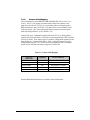
1
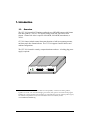
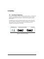
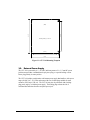
C LT- 3 6 1 C A M E R A L I N K T R A N S L ATO R User’s Manual Document # 201140, Rev 0.1, 2/28/2013 (preliminary) Vivid Engineering 159 Memorial Drive, Suite F • Shrewsbury, MA 01545 Phone 508.842.0165 • Fax 508.842.8930 www.vividengineering.com • [email protected] Table of Contents 1. Introduction 1 1.1. Overview 1 1.2. Features 2 1.3. Functional Description 3 1.3.1. Supported Video Formats 4 1.3.2. HD-SDI Format Indicator 5 1.3.3. Camera Link Mapping 6 1.3.4. Mode Switch 7 1.3.5. Cable Equalizer 8 1.3.6. Deserializer 8 1.3.7. Scan Conversion 8 1.3.8. Test Pattern Generator 9 1.4. Typical Applications 11 1.4.1. Base Configuration Application 11 1.4.2. Medium Configuration Application 12 1.5. Specifications 13 2. Interface 14 2.1. Front Panel Connections 14 2.2. Rear Panel Connections 15 2.3. Cable Shield Grounding 15 3. Mechanical 16 3.1. Dimensions 16 3.2. External Power Supply 17 4. Revision History 18 1. Introduction 1.1. Overview The CLT-361 Camera Link1 Translator enables the use of HD-SDI cameras with Camera Link fame grabbers. The CLT-361 supports 1080p, 1080i, and 720p camera video formats. Camera Link video is output as 24-bit RGB, 30-bit RGB, monochrome, or YCbCr. CLT-361 features include camera format auto-detection, a built-in test pattern generator, and front-panel video format indicator. The CLT-361 supports Camera Link base and medium configurations. The CLT-361 is housed in a sturdy, compact aluminum enclosure. A locking-plug power supply is optional. Vivid Engineering PWR FORMAT Camera Link Translator MEDIUM GRABBER CLT-361 BASE GRABBER 1 The Camera Link interface standard enables the interoperability of cameras and frame grabbers, regardless of vendor. The Automated Imaging Association (AIA) sponsors the Camera Link program including the oversight Camera Link Committee, the self-certification program, and the product registry. The Camera Link specification may be downloaded from the AIA website, found at www.machinevisiononline.org 1 1.2. Features • Enables use of HD-SDI cameras with Camera Link frame grabbers • SMPTE-259M/292M serial digital input • 1920x1080 formats: 59.94/60i, 29.97/30p, 23.98/24p, 25p, 50i • 1280x720 format: 59.94/60p • Auto-detects camera video format • Camera Link “base” configuration output: 24-bit RGB, monochrome, or 4:2:2 YCbCr • Camera Link “medium” configuration output: 30-bit RGB or 4:4:4 YCbCr • Front-panel video format indicator • Rear-panel mode selection switch • Built-in test pattern generator • Isolated DC power input • Multi-nation power supply included, locking-plug version optional • Sturdy, compact aluminum enclosure w/ mounting flange • 3-year warrantee 2 1.3. Functional Description A block diagram of the CLT-361 is provided in Figure 1-1. The CLT-361 performs realtime conversion of HD-SDI video to Camera Link, enabling the use of HD-SDI cameras with Camera Link frame grabbers. CLT-361 functionality is described in the following sections. HD-SDI (BNC) Cable Equalizer Video Processing SMPTE 259M/292M Deserializer - Camera Link Mapping - Scan Conversion - Test Pattern Generator Format Indicator Channel Channel Link Link Transmitters Transmitters Video Data To Camera Link Frame Grabber To HD-SDI Camera Mode Select Switch Image Buffer CLT-361 Camera Link Translator Figure 1-1: CLT-361 Block Diagram The camera interface receives video data from the HD-SDI camera via a 75-ohm coaxial cable. A BNC connector is located on the rear panel of the CLT-361. The CLT-361 frame grabber interface incorporates the connector, signals, pinout, and chipset in compliance with the Camera Link specification. The CLT-361 incorporates the “medium” configuration interface (i.e. 2 connectors). The CLT-361 may be used in either base (single connector) or medium (dual connector) configuration. The interface between the CLT-361 and the frame grabber includes only the video data signals. The frame grabber receives video data, but cannot control or communicate with the camera. The CLT-361 is powered by an external wall plug-in power supply. A multi-nation power supply is standard. Optionally, the CLT-361 is available with a locking-plug power supply. The locking plug reduces the risk of accidental disconnection from the rear-panel power jack. The CLT-361 is also available without power supply. The CLT-361 DC power input is electrically isolated from the internal circuitry. 3 1.3.1. Supported Video Formats The CLT-361 supports many popular, but not all, HD-SDI video formats defined in SMPTE-259M and SMPTE-292M. Table 1.1 identifies the formats supported. Table 1-1: Supported HD-SDI Formats • 1080i @ 59.84 (SMPTE 292M, 1920x1080, 59.94fps, interlaced) • 1080i @ 60 • 1080p @ 29.97 (SMPTE 292M, 1920x1080, 29.97fps, progressive) • 1080p @ 30 • 1080p @ 23.98 (SMPTE 292M, 1920x1080, 23.98fps, progressive) • 1080p @ 24 (SMPTE 292M, 1920x1080, 24fps, progressive) • 1080p @ 25 (SMPTE 292M, 1920x1080, 25fps, progressive) • 1080i @ 50 (SMPTE 292M, 1920x1080, 50fps, interlaced) • 720p @ 59.94 (SMPTE 259M, 1280x720, 59.94fps, progressive) • 720p @ 60 (SMPTE 259M, 1280x720, 60fps, progressive) (SMPTE 292M, 1920x1080, 60fps, interlaced) (SMPTE 292M, 1920x1080, 30fps, progressive) The CLT-361 supported formats include both interlaced (i) and progressive (p) scan video. Camera Link does not include a provision for handling interlaced video and the CLT-361 will automatically convert interlaced video to progressive. See Section 1.3.6 for more information. 4 1.3.2. HD-SDI Format Indicator The CLT-361 automatically detects incoming HD-SDI video and displays the format via three LEDs located on the front panel. The LED codes are shown in Figure 1-2. The LEDs are off when no video is present, when the video input is not supported, and when the CLT-361 is in test pattern mode. 1080i @ 59.84 or 60 1080p @ 29.97 or 30 1080p @ 23.98 or 24 FORMAT FORMAT FORMAT 1080p @ 25 1080i @ 50 FORMAT FORMAT 720p @ 59.84 or 60 FORMAT No Input, Input Not Supported, or Test Patterns Enabled FORMAT Figure 1-2: HD-SDI Format Indicator Codes 5 1.3.3. Camera Link Mapping The color format of received SMPTE-259M/292M HD-SDI video is 10-bit 4:2:2 YCbCr. The CLT-361 outputs video data on the Camera Link interface as raw (unprocessed) 10-bit 4:2:2 YCbCr, or as converted to other color formats such as RGB, monochrome, and 4:4:4 YCbCr. Note that YCbCr is not a standard Camera Link color format. The Camera Link output format is selected via the rear-panel mode dipswitch (positions 1,2,8. See Section 1.3.4). Camera Link “base” configuration (single cable from CLT-361 to frame grabber) supports up to 24-bit video data. Conversion to some output formats yields video data in excess of 24 bits. These modes require a “medium” configuration connection to the frame grabber (i.e. 2 Camera Link cables). Table 1-1 lists the Camera Link video formats supported by the CLT-361, the associated configuration (base or medium), and the way in which the video data is mapped to Camera Link. Table 1-1: Camera Link Mapping Camera Link Configuration Camera Link Mapping 24-bit RGB base 3x8 RGB 10-bit Monochrome base 10-bit single tap 10-bit 4:2:2 YCbCr base 10-bit dual tap (Y=A, CbCr=B) 30-bit RGB medium 3x10 RGB 10-bit 4:4:4 YCbCr medium 30-bit RGB (Cr=R, Y=G, Cb=B) Camera Link Video Format Note that RGB and monochrome are common Camera Link formats. 6 1.3.4. Mode Switch The CLT-361 incorporates an 8-position switch on the rear panel for selecting the various operating modes. The mode switch positions are defined in Figure 1-3. 1 2 3 4 5 6 7 8 YCbCr Select 0 1 - 4:4:4 - 4:2:2 Spare (future use) 0 1 - reserved - reserved Test Pattern Format 00 01 10 11 - 1080 @ 30 1080 @ 25 1080 @ 24 720 @ 60 Test Pattern Select 0 1 - Color bars - Diagonal wedge Test Pattern Enable 0 1 - Patterns off (normal) - Patterns on Camera Link Format 00 01 10 11 1 = "up" switch position 0 = "down" switch position - 24-bit RGB 10-bit Monochrome 30-bit RGB YCbCr Figure 1-3: Mode Switch Definition 7 1.3.5. Cable Equalizer The CLT-361 incorporates an adaptive cable equalizer for receiving the SMPTE 259M / 292M HD-SDI signal input. The equalizer performs DC restoration and corrects for dispersive losses associated with long coaxial cable transmission. The adaptive equalizer is SMPTE 259M and SMPTE 292M compliant and equalizes up to 200 meters of Belden 1694A coaxial cable. 1.3.6. Deserializer The CLT-361 incorporates a deserializer device that is SMPTE 292M and SMPTE 259M compliant and deserializes/decodes 1.485Gbps (or 1.483Gbps) serial component video data to 20-bit parallel data with a synchronized parallel word-rate clock.. Functions performed by the deserializer include clock/data recovery from the serial data, serial-to-parallel data conversion, SMPTE standard data decoding, NRZI-toNRZ conversion, parallel data clock generation, word framing, CRC and EDH data checking and handling, and automatic video format determination. 1.3.7. Scan Conversion The CLT-361 supports both progressive scan and interlaced scan HD-SDI video. Interlaced scan, in which a video frame is split into two fields (i.e. odd and even lines) and transmitted one field at a time, is not supported by Camera Link. To support interlaced video , the CLT-361 performs a scan conversion in which the incoming interlaced video frame is first stored to an image buffer. The video buffer is then output in progressive fashion. This resequencing occurs automatically a supported HD-SDI interlaced format is detected. Note that the scan conversion causes an additional delay (i.e. latency) in the video path of approximately one frame time (i.e. 33 ms for 1080i @ 60). The progressive (p) video formats do not require scan conversion and do not incur the associated delay. 8 1.3.8. Test Pattern Generator The CLT-361 incorporates a built-in test pattern generator. The test pattern generator is useful for verifying the link between the CLT-361 and frame grabber, and for ensuring that the frame grabber is properly setup to acquire the converted video from the HD-SDI camera. The test pattern generator may be used with or without a camera connected. The test pattern generator is enabled and controlled via the rear-panel mode dipswitch (see Section 1.3.4). When test pattern generation is enabled (switch position 3 “up”), an internal test pattern generator replaces the camera as video source. When test pattern generator is enabled, the front panel format indicator LEDS are off, regardless if a camera is connected. Test patterns are generated with image size of either 1920x1080 or 1280x720 and at a variety of frame rates as selected by the mode switch test pattern format field (switch positions 5&6). Two test patterns are available, color bars or diagonal wedge. Pattern selection is made with mode switch position 4. Figures 1-4 and 1-5 illustrate color bar and diagonal wedge patterns, respectively. Figure 1-4: Color Bars Test Pattern 9 Figure 1-5: Diagonal Wedge Test Pattern 10 1.4. Typical Applications 1.4.1. Base Configuration Application A CLT-361 application using Camera Link “base” configuration is shown in Figure 1-6. An HD-SDI camera is connected to the BNC connector on the rear panel via a HD-SDI 75-ohm coaxial cable. A single Camera Link cable is connected from the “base” connector on the CLT-361 front panel to the frame grabber. In this example Camera Link video is being output as 24-bit RGB, a common format. The associated rear-panel dipswitch settings for this mode is all switch positions “down”. CLT-361 Camera Link Translator HD-SDI Camera Vivid Engineering PWR FORMAT Camera Link Translator MEDIUM GRABBER CLT-361 BASE GRABBER Camera Link Frame Grabber Figure 1-6: Base Configuration Application 11 1.4.2. Medium Configuration Application A CLT-361 application using Camera Link “medium” configuration is shown in Figure 1-7. An HD-SDI camera is connected to the BNC connector on the rear panel via a HD-SDI 75-ohm coaxial cable. Two Camera Link cables are used to connect the CLT-361 to the frame grabber. In this example Camera Link video is being output as 30-bit RGB which is Camera Link medium configuration (2 cables required). The associated rear-panel dipswitch settings for this mode is switch position 1 “up”, and all other switch positions “down”. CLT-361 Camera Link Translator HD-SDI Camera Vivid Engineering PWR FORMAT Camera Link Translator MEDIUM GRABBER CLT-361 BASE GRABBER Camera Link Frame Grabber Figure 1-7: Medium Configuration Application 12 1.5. Specifications Table 1-2: CLT-361 Specifications Feature Specification Camera Interface SMPTE-259M/292M serial digital input (HD-SDI) Camera Connector BNC (75 ohm) Camera Formats - 1920x1080: 59.94/60i, 29.97/30p, 23.98/24p, 25p, 50i - 1280x720: 59.94/60p Frame Grabber Interface Camera Link “base” or “medium” configuration Frame Grabber Conn. 26-pin MDR type Camera Link Video - Base config: 24-bit RGB, 10-bit monochrome, 4:2:2 YCbCr - Medium Config: 30-bit RGB, 4:4:4 YCbCr - Pixel clock: 74 MHz (approx.) - Color bar and monochrome wedge test patterns Mode Selection Rear-panel 8-position DIP switch Power Supply Universal wall style w/ outlet plug set Power Plug 2.1 x 5.5 mm, center-positive. Locking style optional. Power Requirements 4.5 – 9 VDC, internally isolated 670 mA @ 5 VDC (typical) Cabinet Dimensions 5.28” (L) x 1.18” (H) 6.12” (D) Weight 14 oz Operating Temperature Range 0 to 50° C Storage Temperature Range -25 to 75° C Relative Humidity 0 to 90%, non-condensing 13 2. Interface 2.1. Front Panel Connections The CLT-361 Camera Link Translator front panel is shown in Figure 2-1. The front panel contains two 26-pin MDR video connectors for connecting to the Camera Link frame grabber. The front panel also incorporates a 3-LED video format indicator and LED power indicator. The MDR-26 video connectors and signal assignments comply with the Camera Link “base” and “medium” configurations. The connector assignments are as defined for the camera interface in the Camera Link Specification. This arrangement provides compatibility with standard Camera Link cables. Vivid Engineering PWR FORMAT Camera Link Translator MEDIUM GRABBER CLT-361 BASE GRABBER Figure 2-1: CLT-361 Front Panel 14 2.2. Rear Panel Connections The CLT-361 Camera Link Translator rear panel is shown in Figure 2-2. The rear panel contains a standard 75-ohm BNC connector for connecting to the HD-SDI camera, an 8position mode switch, and the DC power jack. The DC power jack accepts either a standard 2.1 x 5.5 mm barrel-style power plug or a special locking plug. The locking plug has bayonet-style “ears” on the barrel. Once inserted, the plug is turned ¼ turn clockwise. This locks the connection and provides retention. Plug polarity is center-positive. Recommended locking power plug is Philmore part number 2150. SDI INPUT MODE 4.5-9 VDC Figure 2-2: CLT-361 Rear Panel 2.3. Cable Shield Grounding The Camera Link interface cable “outer” shields are connected to the CLT-361 aluminum case. Case and endplate contacting surfaces are unpainted, providing a Faraday cage to shield internal circuitry. The case is isolated from the CLT-361 circuitry and the cable “inner” shields. The Camera Link interface cable “inner” shields connect to circuit digital ground, maintaining signal reference levels between the CLT-361 and the frame grabber. The HD-SDI 75-ohm coaxial cable BNC connector is isolated from the CLT-361 aluminum case. 15 3. Mechanical 3.1. Dimensions The CLT-361 Camera Link Translator cabinet dimensions are shown in Figure 3-1. ou nt in g fla CLT-361 m Camera Link Translator PWR FORMAT MEDIUM GRABBER BASE GRABBER 6. 12 "( in cl ud in g 1.18" Vivid Engineering ng e) The CLT-361 is housed in a sturdy aluminum enclosure. The body is extruded aluminum, with detachable front and rear endplates. The enclosure incorporates a mounting flange. The flange contains four predrilled holes (0.15” diameter) for convenient equipment mounting. A mounting footprint drawing is provided in Figure 3-2. 5.28" Figure 3-1: CLT-361 Cabinet Dimensions 16 5.62" 6.12" (Rear) Mounting Holes (4): 0.15" dia (Front ) 5.00" 5.28" Figure 3-2: CLT-361 Mounting Footprint 3.2. External Power Supply The CLT-361 is powered by 4.5 – 9.0 VDC and incorporates a 2.1 x 5.5 mm DC power jack that accepts either a standard barrel-style power plug, or a special locking version. Power plug polarity is center-positive. The CLT-361 includes a multi-nation wall-mount power supply that handles a wide power range (90-264 VAC, 47-63 Hz) and comes with a set of outlet plugs suitable for most countries (US, Europe, UK, etc). The CLT-361 may also be purchased with a lockingplug power supply, or without power supply. The locking plug reduces the risk of accidental disconnection from the rear-panel power jack . 17 4. Revision History Table 5-1: CLT-361 User’s Manual Revision History Document ID # Date 201140-0.1 2/28/2013 Changes Preliminary release of manual 18