1
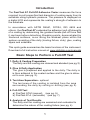
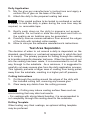
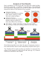
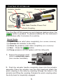
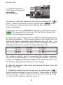
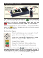
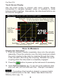
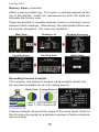
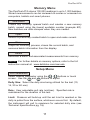
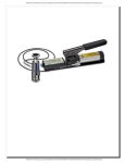
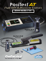
Quick Guide v. 5.0
PosiTest AT-A
(automatic)
PosiTest AT-M
(manual)
Introduction
The PosiTest AT Pull-Off Adhesion Tester measures the force
required to pull a specified test diameter of coating away from its
substrate using hydraulic pressure. The pressure is displayed on
a digital LCD and represents the coating's strength of adhesion to
the substrate.
In accordance with ASTM D4541, D7234, ISO 4624 and
others, the PosiTest AT evaluates the adhesion (pull-off strength)
of a coating by determining the greatest tensile pull-off force that
it can bear before detaching. Breaking points, demonstrated by
fractured surfaces, occur along the weakest plane within the
system consisting of the dolly (loading fixture, stub), glue, coating
layers and substrate.
This quick guide summarizes the basic functions of the instrument.
Download a full instruction manual at: www.defelsko.com/manuals
Basic Steps to Perform a Pull-Off Test
1. Dolly & Coating Preparation
The dolly and the coating are cleaned and abraded (see pg.2).
2. Glue & Dolly Application
The glue is prepared and applied to the dolly. The dolly is
is then adhered to the coated surface and the glue is allowed to cure (see pg. 2).
3. Test Area Separation - optional
The test area of the coating is isolated from the area
surrounding the dolly by cutting or drilling (see pg. 3).
4. Pull-Off Test
a) PosiTest AT-M (manual) (see pg. 5)
b) PosiTest AT-A (automatic) (see pg. 7)
5. Analysis of Test Results
The dolly and the coating are examined and evaluated to
determine the nature of the coating failure (see pg. 4).
1
Dolly & Coating Preparation
Dolly Preparation
1. To remove oxidation and contaminants, place the included
abrasive pad on a flat surface and rub the base of the dolly
across the pad 4-5 times.
2. As required, remove residue left from the abrading process
using a dry cloth or paper towel.
Coating Preparation
1. Lightly roughen the coating using the included abrasive pad.
NOTE: As coating abrasion may introduce flaws, it should
only be used when necessary to remove surface contaminants,
or when the bond strength between the glue and the coating
is insufficient for pull testing.
2. To promote the bond between the dolly and the coating,
degrease the area of the coating to be tested using alcohol or
acetone to remove any oil, moisture or dust.
NOTE: Ensure that any alternative abrasion techniques,
degreasers or adhesives do not alter the properties of the coating.
Test by applying a small amount of degreaser or glue to a sample
area and observing effects.
Glue & Dolly Application
Glue Selection
The glue included in the PosiTest Adhesion Tester kit has been
selected due to its versatility. This glue has minimal impact on a
variety of coatings and has a tensile strength exceeding the
maximum performance capabilities of the pressure system under
ideal conditions. Other glues may be preferred based on
requirements such as cure time, coating type, working temperature
and pull-off strength. Quick curing one-part cyanoacrylates (super
glues) may be sufficient for painted surfaces, but two-part epoxies
are preferred for porous or rough coatings.
2
Dolly Application
1. Mix the glue per manufacturer’s instructions and apply a
uniform film of glue on the base of the dolly
2. Attach the dolly to the prepared coating test area.
NOTE: If the coated surface to be tested is overhead or vertical,
a means to hold the dolly in place during the cure time may be
required, i.e. removable tape.
3.
4.
5.
Gently push down on the dolly to squeeze out excess
adhesive. Do not twist or slide the dolly back and forth on
the coating as air bubbles may be generated.
Carefully remove excess adhesive from around the edges
of the dolly with included cotton swabs.
Allow to cure per the adhesive manufacturer's instructions.
Test Area Separation
The decision of when to cut around a dolly is dependent on the
standard, specification or contractual agreement to which the test
is to comply. The primary purpose for cutting through the coating
is to isolate a specific diameter test area. When the decision to cut
into the coating has been made, it is recommended to cut all the
way through to the substrate. As a minimum, it is suggested to
carefully cut away excess glue from the dolly application process.
This typically prevents a larger area of coating from being pulled
away from the substrate, resulting in a higher pull-off pressure.
Cutting Instructions
1. Cut through the coating around the edges of the dolly with
the included cutting tool, removing any excess glue.
2. Clear away any debris from the cutting process.
NOTE: - Cutting may induce coating surface flaws such as
microcracking that may alter test results.
- For coatings with strong lateral bonding, it is recommended to
cut completely through the coating down to the substrate.
Drilling Template
When testing very thick coatings, an optional drilling template
may be preferred.
3
Analysis of Test Results
Upon completion of the pull-off test, the dolly and coated surface
should be examined. In addition to pull-off force, many National
and International standards such as ASTM D4541 and ISO 4624
require the nature of the fracture to be recorded.
Cohesive fracture:
fracture occurs within a coating
layer (same coating on dolly
face and coated surface).
Dolly Face
Coated Surface
Adhesive fracture:
fracture occurs at the interface
between layers (coating on
dolly face differs from surface).
Glue failure: visible separation of the glue from itself,
the coating or dolly (no coating visible on the dolly face).
Dolly
Glue
Substrate
Cohesive fracture
(intercoat)
Adhesive fracture
(between layers)
Glue failure
(coating/glue)
Glue failures typically occur when the glue is improperly mixed or
the coated surface has not been adequately prepared (see pg.2).
The PosiTest AT-A model provides an interface to document the
nature of the fracture for each pull-off test (see pg. 10). Fracture
results are included in test reports.
4
PosiTest AT-M Manual
Actuator Handle
Hose
Display
Pump Handle
Pump
Actuator
Assembly
USB Data Transfer /Power Port
Quick Coupling
The PosiTest AT-M powers-up and displays dashes when the
button is pressed. To preserve battery life, the instrument
powers-down after 5 minutes of no activity.
Quick Guide
(1) Open pressure relief valve completely (turn counter clockwise)
(2) Connect the actuator to the dolly
(3) Close the pressure relief valve completely (turn clockwise)
(4) Zero - Press the
button
(5) Pump pressure into the system until the dolly pulls
1. Ensure the pressure relief
valve is completely open.
(turn counter clockwise)
OPEN
2. Push the actuator handle completely down into the actuator
assembly. Place the actuator over the dolly head and attach the
quick coupling to the dolly by reaching through the holes in the
actuator and lifting the coupling. Release the quick coupling when
the dolly head is completely engaged.
5
PosiTest AT-M
3. Close the pressure
relief valve on the pump
completely
(turn clockwise).
CLOSE
As required, verify and adjust the dolly size by pressing the
button. Select the pressure units by pressing the
button.
The instrument will maintain these settings even after the
button is pressed.
4. Zero the instrument BEFORE pumping by pressing the button.
This prepares the instrument for the test by clearing the
display, and zeroing the instrument.
5. Prime the pump slowly until the displayed reading approaches
the priming pressure. The priming pressure is the point that the
instrument begins calculating and displaying the pull rate. It is
also the pressure at which the ability to store readings is enabled.
Priming pressures for the various dolly diameters are:
10 mm
14 mm
20 mm
50 mm
400 psi
200 psi
100 psi
50 psi
2.8 MPa
1.4 MPa
0.7 MPa (default setting)
0.4 MPa
For optimum results, prior to exceeding the priming pressure,
return the pump handle to its full upright position and then
complete a single continuous stroke at the desired pull rate until
the actuator separates the dolly from the coating.
6. Open the pressure relief valve and remove the dolly from the
actuator assembly.
7. Readings may be stored into memory by pressing the
button (memory storage for up to 200 pulls). Press again to review
stored readings. Stored measurements can be accessed using
our PosiSoft 3.0 desktop software (pg. 14).
6
PosiTest AT-A Automatic
Touch Screen Display
AC Adapter Port
(Charges batteries
and powers
instrument)
Hose
Actuator
Handle
Actuator
Assembly
USB Port
Quick Coupling
The PosiTest AT-A powers-up when the
button is pressed.
To preserve battery life, the instrument powers-down after 5
minutes of no activity. Alternatively, press and hold the
button for 5 seconds or select Power Off from the menu.
Instrument functions are menu controlled. To access the Menu,
press the
button. Navigate using the multifunction keypad
or touch screen display.
Multifunction Keypad
Directional buttons are used to navigate through
menu options and adjust parameters.
Note: Some menus display on more than a
single view. Use the
or
buttons or swipe
the touch display to switch between views.
Access Menu / Select
Power On / Start Test / Return to Main View
Stop Test / Power-down (hold for 5 seconds)
Screen Capture: Press both
buttons at any time to copy
and save an image copy of the the current display. The last 10
screen captures are stored in memory and can be accessed when
connected to a computer (see PosiSoft USB Drive pg. 14).
7
PosiTest AT-A
Touch Screen Display
Use the touch screen to interact with menu options. Swipe
horizontally to navigate between views or vertically to move
between batch readings. Alternatively, the directional buttons can
be used for navigation.
Main View (shown with memory batch open)
Carousel: indicates the current view. Swipe horizontally
or use arrow keys to switch between views.
(see pg.10)
Pull Chart
displays
pressure
over time
Current
Reading
Dolly
Size
Limit Hold Time
Pull Rate
Pull Parameters (pg.11)
Battery
WiFi Bluetooth USB
(Status icons)
How to Measure
Prepare the Instrument
1. Push the actuator handle completely down into the actuator
assembly. Place the actuator over the dolly head and attach
the quick coupling to the dolly by reaching through the holes
in the actuator and lifting the coupling. Release the quick
coupling when the dolly head is completely engaged.
2. Press the
button to power-up the instrument if necessary.
3. Verify Pull Parameters (pg. 11) are set to the preferred dolly
size, pull rate, pull limit and hold time. Change if necessary.
NOTE: If recording of test results is desired, a memory batch
must be opened prior to the test. Select New Batch from the
Memory menu (pg. 11).
8
Perform the Test
4. Press the
PosiTest AT-A
button to initiate the test.
The instrument begins building pressure (priming stage) and a
green animated arrow (up) appears on the display. When the
priming pressure is achieved the LCD starts displaying pressure
over time on the pull chart. Refer to step 5 (pg. 6) for Priming
Pressures.
Pressure build-up stops when the dolly is pulled from the
surface, the pull limit has been reached or when the
button
is pressed. The maximum pressure value will blink on the display
and a red animated arrow (down) will display while the pump
retracts the actuator.
CAUTION: To avoid injury, keep fingers away from the
quick coupling and actuator assembly until the pull test
has completed and the actuator has been fully retracted. Press the
stop button to abort the pull test at any time.
NOTE: Setting a Pull Limit or stopping the test before a fracture
occurs is useful when the coating strength exceeds specified
requirements.
5. Remove the dolly from the actuator assembly.
6. Examine the dolly and surface to analyze the result (pg. 4).
Recording the Result
If a memory batch is open, the maximum pressure result is
automatically stored into memory (pg.11). Pass/fail, pull
parameters, date and time are also recorded.
The nature of the fracture (cohesive, adhesive, glue), batch and
reading notes can also be recorded. Swipe the touch screen
horizontally or use the left/right buttons to navigate to the
appropriate view and select Edit. See Memory Views (pg. 10).
All stored measurement data can be accessed using PosiSoft
solutions (pg. 13).
9
PosiTest AT-A
Memory Views (carousel)
When a memory batch (pg. 11) is open, a carousel appears at the
top of the display. Views are represented by dots, the solid dot
indicates the current view.
Swipe horizontally to navigate between views or vertically to move
between batch readings. Alternatively, the directional buttons can
be used for navigation. Six views are available:
Main View
Reading List
Reading Summary
Layer/Fracture
Reading Note
Batch Note
Recording Fracture Analysis
The cohesive and adhesive fracture visual analysis results can
be recorded (available for up to 5 coating layers).
Dolly Face Coated Surface
Layer 2
Layer 1
Layer 2: 50% Cohesive (C)
Layer 1: 50% Cohesive (B)
Fracture analysis is beyond the scope of this quick guide. Refer to
the full instruction guide for a detailed overview of fracture analysis
and recording.
10
Memory Menu
PosiTest AT-A
The PosiTest AT-A stores 100,000 readings in up to 1,000 batches.
Stored measurements can be reviewed on-screen or accessed via
computers, tablets and smart phones.
New Batch
Closes any currently opened batch and creates a new memory
batch, named using the lowest available number (example: B2).
New batches are date stamped when they are created.
Open
Selects a previously created batch to open and make current.
Close
Stops the recording process, closes the current batch, and
removes batch information from the display.
Delete
Removes a batch and associated measurements from memory.
NOTE: For further details on memory options, refer to the full
instruction manual at: www.defelsko.com/manuals
Setup Menu
Pull Parameters
Select desired parameter using the
buttons or touch
screen. Use the
and
buttons to adjust.
Dolly Size: Select the dolly size being utilized for the test (10,
14, 20 or 50 mm)
Rate: User selectable pull rate (unit/sec). Specified rate is
maintained for the duration of the test.
Limit: Pressure will build-up until the set Limit is reached or the
dolly is pulled from the surface, whichever occurs first. By default,
the instrument will pull to maximum for selected dolly size (see
Technical Specifications pg. 16).
11
PosiTest AT-A
Hold Time:
(up to 60 seconds)
pressure is
maintained (held)
at defined Limit.
Default: 0 seconds.
Hold Time is
displayed on
the pull chart
(shaded area).
Defined
Hold Time
Orientation
Rotates display between landscape (default) or portrait views.
Ideal for use in horizontal or vertical positions.
Units
Converts the display from psi, MPa, N/mm2 or Newtons (unit of
force). Existing measurements in memory are not converted.
Switching units closes Memory.
Gage Info
Displays the model number & serial number, PosiSoft.net
registration key, the amount of remaining memory for storage of
readings, date and time, and software packages.
For security purposes, the registration key is required to add the
Gage to your PosiSoft.net account (pg. 14).
Reset
Restores factory settings and returns the instrument to a known
condition. The following occurs:
- All batches, stored readings, notes, batch names and screen
captures are erased.
- Menu settings are returned to the following:
Memory = OFF
Pull Parameters = default
Orientation = Landscape
Bluetooth = ON
WiFi = OFF
USB Drive = ON
Units = psi
Backlight = Sun
Language = English
NOTE: Date, Time and WiFi are not affected by a Reset.
12
Connect Menu
PosiTest AT-A
PosiSoft.net
Select Sync Now to immediately synchronize stored measurement
data via USB or WiFi to PosiSoft.net (pg.14). PosiSoft Desktop
Manager and an internet connection are required when using USB.
The instrument automatically attempts synchronization with
PosiSoft.net when initially connected via USB to a PC running
PosiSoft Desktop Manager.
NOTE: Additional measurements added to memory while
connected are synchronized only when the USB cable is
disconnected, then reconnected or when the Sync Now option is
selected.
USB Drive
The instrument uses a USB mass storage device which provides a
simple interface to retrieve data in a manner similar to USB flash
drives, cameras or digital audio players.
Bluetooth Smart
Allows communication with a smart device running the PosiTector
App (pg.14) via
wireless technology. No pairing
required. When connected, measurement data is automatically
transfered. Select Send Now to manually transfer batches (useful
when switching between smart devices).
WiFi
Allows wireless communication with devices such as tablets,
smart phones and computers connected to your local wireless
network or portable mobile hot spot. See www.defelsko.com/WiFi
Updates
Determines if a software update is available for your instrument.
See www.defelsko.com/update
WARNING:
The instrument will perform a Reset after an update (pg. 12).
13
Accessing Stored Measurement Data
PosiSoft solutions for viewing, analyzing and reporting data:
PosiTest AT (all models)
PosiSoft 3.0 - Desktop software for downloading, viewing,
printing and storing measurement data.
Customizable reporting tools allow you to add pictures and
screen captures, notes and annotations, add or remove sections
(drag and drop), change headings and more. Save your custom
layouts as templates for future use.
PosiTest AT-A
In addition to PosiSoft 3.0, the PosiTest AT-A is also compatible
with the following solutions...
PosiSoft USB Drive - connect to a PC/Mac using the supplied
USB cable to access and print stored readings, graphs, notes
and screen captures. No software or internet connection
required. USB Drive must be selected. (see pg.13)
PosiSoft.net - a free web-based application offering secure
centralized storage of instrument readings. Access your data
from any web connected device. Go to: www.PosiSoft.net
PosiTector App - Wirelessly transfer measurement data to your
Apple iOS or Android smart device. Create, customize and
share professional PDF reports quickly and easily. The
PosiTector App is available on the iTunes App Store and
Google Play.
For more information on the PosiSoft suite of software, visit:
www.defelsko.com/posisoft
14
Power Supply / Charging
PosiTest AT-M (manual)
Power Source: Built-in rechargeable NiMH battery**
~60 hours continuous with full charge
The built-in rechargeable NiMH batteries are charged using the
included USB AC power supply/charger. Ensure batteries are
charged prior to use. The battery icon will blink while the
instrument is charging and disappear when fully charged. The
charging process will take up to 14 hours depending on remaining
battery power.
Alternatively, the AC power supply or any computer USB port can
be used to power and charge the instrument.
**Do not attempt to remove or replace the PosiTest AT-M internal NiMH
battery pack. In the unlikely event power issues are experienced,
please contact our technical support for assistance.
PosiTest AT-A (automatic)
Power Source: Built-in rechargeable NiMH battery
>200 pulls with full charge
The built-in rechargeable NiMH batteries are charged using the
included AC power supply/charger. Ensure batteries are charged
prior to use. The USB port will not charge or power the PosiTest
AT-A.
The charging process will take 2-3 hours depending on remaining
battery power. Alternatively, the AC power supply can be used to
power the instrument.
The
icon will display while the instrument is charging.
When fully charged the
icon will appear.
NOTE:
The PosiTest AT-A internal NiMH battery pack is user
replaceable. In the unlikely event power issues are experienced,
please contact our technical support or your local dealer for OEM
battery pricing, availability and detailed replacement instructions.
15
Calibration
Calibration and Verification
The PosiTest AT is shipped with a Certificate of Calibration
showing traceability to a national standard. For organizations with
re-certification requirements, the PosiTest AT may be returned at
regular intervals for calibration. DeFelsko recommends that our
customers establish their instrument calibration intervals based
upon their own experience and work environment. Based on our
product knowledge, data and customer feedback, a one year
calibration interval from either the date of calibration, date of
purchase, or date of receipt is a typical starting point.
Verification
The PosiTest AT Verifier is available for verifying the accuracy and
operation of PosiTest Adhesion Testers and is an important
component in fulfilling both ISO and in-house quality control
requirements. Fully portable with hardshell carry case for use in
the field or laboratory. Learn more at: www.defelsko.com/at/verifier
Technical Data
Conforms to: ASTM D4541, ASTM D7234, ISO 4624 and others.
Specifications:
Resolution: 1 psi (0.01 MPa)
Dolly Size (mm)
Accuracy: ±1% Full Scale
Max Pull-Off
Pressure (AT-M)
Max Pull-Off
Pressure (AT-A)
6,000 psi (40 MPa)
7,000 psi (50 MPa)
500 psi (3.5 MPa)
560 psi (3.8 MPa)
10 mm
10,000 psi (70 MPa) 14,000 psi (96 MPa)
20 mm
3,000 psi (20 MPa)
14 mm
50 mm
3,500 psi (24 MPa)
*requires the use of a 50 mm stand off
The instrument also measures in N/mm2 and Newtons (unit of
force). See Units (pg. 12).
16
Returning for Service
There are no user serviceable components. Any service must be
performed by DeFelsko Corporation.
If you need to return the instrument for service, describe the
problem fully and include reading results, if any. Be sure to include
contact information including your company name, company
contact, telephone number and fax number or email address.
Website: www.defelsko.com/support
Limited Warranty, Sole Remedy
and Limited Liability
DeFelsko's sole warranty, remedy, and liability are the express
limited warranty, remedy, and limited liability that are set forth on
its website: www.defelsko.com/terms
www.defelsko.com
© 2015 DeFelsko Corporation USA
All Rights Reserved
This manual is copyrighted with all rights reserved and may not be reproduced or transmitted,
in whole or part, by any means, without written permission from DeFelsko Corporation.
DeFelsko, PosiTector, PosiTest and PosiSoft are trademarks of DeFelsko Corporation
registered in the U.S. and in other countries. Other brand or product names are trademarks
or registered trademarks of their respective holders.
Every effort has been made to ensure that the information in this manual is accurate.
DeFelsko is not responsible for printing or clerical errors.
17
33
m
74
k 28
c 33
m
www.defelsko.com
© 2015 DeFelsko Corporation USA
All Rights Reserved
This manual is copyrighted with all rights reserved and may
not be reproduced or transmitted, in whole or part, by any means,
without written permission from DeFelsko Corporation.
DeFelsko, PosiTest, PosiTector and PosiSoft are trademarks of
DeFelsko Corporation registered in the U.S. and in other
countries. Other brand or product names are trademarks or
registered trademarks of their respective holders.
Every effort has been made to ensure that the information in
this manual is accurate. DeFelsko is not responsible for
printing or clerical errors.
19
19