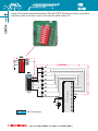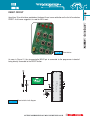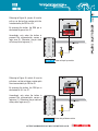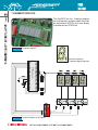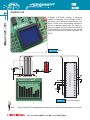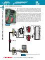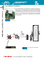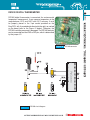
1
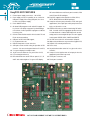
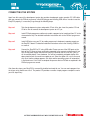
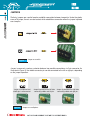
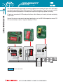
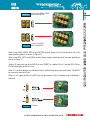
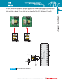
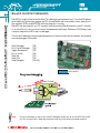
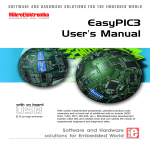
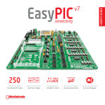
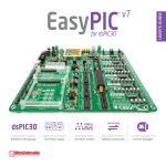
CONTENTS
EasyPIC5 KEY FEATURES
CONNECTING THE SYSTEM
INTRODUCTION
Switches
Jumpers
MCU Sockets
Power Supply
On-Board USB 2.0 Programmer
Oscillator
mikroICD (Hardware In-Circuit Debugger)
LEDs
Reset Circuit
Push Buttons
7-segment Displays
2x16 Character LCD
Graphic LCD
Touch Panel
RS-232 Communication Module
USB Communication Module
PS/2 Communication Module
DS1820 Digital Thermometer
A/D Converter Test Inputs
Direct Port Access Connectors
4
5
6
7
8
9
11
12
14
16
17
19
20
22
23
24
25
26
27
28
29
30
32
4
EasyPIC5 KEY FEATURES
1. External power supply connector 8 - 16V AC/DC;
2. Power supply selector. It is possible to use external or
USB power supply. When using USB port, there is no
need for external power supply;
3. Power ON/OFF switch;
4. On-board USB programmer with mikroICD support. Its
key feature is an ability to upgrade. By downloading a
new software, it will be possible to program new MCUs
in coming years;
5. RS-232 communication module with selectable TX and
RX for all microcontrollers;
6. USB port for MCU with USB support;
7. PC keyboard connector;
8. DS1820 temperature sensor connector;
9. A/D input selector used for testing the operation of A/D
converter. It is connected to potentiometers P1 and P2;
10. 7- segment displays in multiplex mode;
11. 16-pin connector allows an easy connection of LCD;
12. LCD contrast potentiometer;
13. DIP switch SW6 turns on/off LEDs on ports A, B, C, D
and E and enables digits on 7-segment LED display.
DIP switch SW9 turns on/off touch panel controller, PS/2
and LCD and GLCD backlights;
14. EasyPIC5 supports microcontrollers in DIP8, DIP14,
DIP18, DIP20, DIP28 and DIP40 packages;
15. Jumper to determine port performance in idle state (pullup/pull-down). Select pull-up to enable port pins to detect
logic zero (0) and vice versa;
16. PORTA connected to a resistor network using DIP switch
SW1. If a switch is OFF, the appropriate pin does not have
a resistor attached. It enables PORTA pins to be used in
analog mode as well as digital I/O pins. The same applies
to other ports: PORTB, PORC, PORTD and PORTE;
17. 36 LEDs connected to the microcontroller I/O ports;
18. 20-pin connector allows an easy connection of graphic LCD;
19. Graphic LCD contrast potentiometer;
20. Reset circuit;
22. 36 push buttons allow control of every pin on the microcontroller;
21. Jumper to select high/low state of an input pin when the
appropriate push button is pressed;
23. Touch panel connector; and
24. Touch panel controller.
CONNECTING THE SYSTEM
5
Step no.1
Take the development system and product CD out of the box. Insert the product CD into
CD drive. Do not connect the development system to a PC yet.
Step no.2
Install PICflash programmer software to enable a program to be transferred from PC to the
microcontroller chip. For detailed installation instructions refer to the PICflash programmer
manual.
Step no.3
Install USB drivers on your PC to enable programmer's hardware to operate properly on
the EasyPIC5 board. For detailed installation instructions refer to the Installing USB drivers manual.
Step no.4
Connect the EasyPIC5 to PC using USB cable. Please use one of the USB ports on the
back of the PC because these are directly connected to the computer motherboard. If you
turn ON the power supply switch on the EasyPIC5 board for the very first time, your PC
will immediately detect a new hardware. You will be immediately prompted whether Windows should search for new drivers update or not. Select the option No, not this time and
click Next. Another window appears, click Next and the operating system will automatically find the drivers. Click Finish to complete this process and run PICflash as explained in the
PICflash programmer manual.
After these four steps, your EasyPIC5 is successfully installed and ready for use. You can read a program from
the chip or write another one into it. The product CD provides numerous simple program examples to make
your first steps Easy...
.
CONNECTING THE SYSTEM
Apart from this manual, the development system box contains development system, product CD, USB cable
and user manuals for PICflash programmer, mikroICD Debugger and Installing USB drivers. In order to use the
EasyPIC5 properly, it is necessary to go through the following steps:
INTRODUCTION
6
INTRODUCTION
The EasyPIC5 is a full-featured development system for almost all Microchip PIC microcontrollers.
It is designed to allow students and engineers to easily test and explore the capabilities of PIC
microcontrollers. It also allows PIC microcontrollers to be interfaced with external circuits and a
broad range of peripheral devices. The user can therefore concentrate on software development
only.
Figure 1 illustrates the EasyPIC5 development system. There are identification marks next to each
component on a silkscreen, both on the top and bottom. These marks describe connection to the
microcontroller, operation modes and provide additional useful information so that there is almost no
need for additional schematics.
Figure 1
EasyPIC5 development system
The EasyPIC5 development system features a number of peripheral devices. In order to enable
these before programming, the appropriate jumpers or switches have to be properly set. Switches
are mechanical devices used to establish or break connection between two contacts. As for this system, switches are grouped in nine DIP switches.
DIP switches SW1 - SW5 are used to enable external pull-up/pull-down resistors on port pins. Each
pull-up/pull-down resistor is individually enabled.
DIP switch SW6 is used to enable/disable LEDs connected to the microcontroller ports. Each group
of 8 port LEDs has its own switch. Four lower switches in this group are used to enable/disable 7segment LED displays. Each display digit can be individually enabled.
DIP switches SW7 and SW8 select MCU pins to be used as RX or TX in serial communication.
DIP switch SW9 is used to control both LCD backlights, communication via PS/2 connector and
touch panel driver.
Figure 2 illustrates the DIP switch SW9. As seen, switches 1, 2, 3 and 4 are ON, whereas 5, 6, 7
and 8 are OFF.
Figure 2
DIP switch SW9
7
SWITCHES
SWITCHES
JUMPERS
8
JUMPERS
Similarly, jumpers are used to break or establish connection between two points. Under the plastic
cover of a jumper, there is a metal contact which establishes connection when the jumper is placed
over two pins.
Figure 3
Jumper as a switch
Jumper is commonly used as a selector between two possible connections via 3-pin connector. As
illustrated in Figure 4, the middle connector pin can be connected to the left or right pin, depending
on the jumper’s position.
Jumper is not placed and
middle pin is unconnected.
Figure 4
Jumper is placed on the left side
connecting middle and left pin.
Jumper as a multiplexer
Jumper is placed on the right side
connecting middle and right pin.
MCU SOCKETS
9
MCU SOCKETS
The EasyPIC5 comes with a 40-pin microcontroller PIC16F887. The user can remove this microcontroller and fit another one in DIP40, DIP28, DIP20, DIP18, DIP14 or DIP8 package into MCU socket.
Figure 5
MCU sockets
Note:
There are two DIP18 sockets with different pinouts (DIP18A and DIP18B). If you use 18-pin microcontrollers, make sure to select the right socket. For example, PIC18F1220 uses DIP18A socket,
while PIC16F628A uses DIP18B socket.
All 8-pin microcontrollers use DIP8 socket. The exception is PIC10F family which uses 10F MCU socket.
Note:
Since all packages have parallel connections, it is not allowed to have more than one microcontroller on the board at a time.
Note:
Some of the 28-pin PIC microcontrollers use the seventh pin as RA5, while some of them use this
pin as VCC. Depending on this, jumper J18 must be set in RA5 and VCC position, respectively. For
example, if you use the PIC18F2331 microcontroller, jumper J18 has to be set in VCC position.
MCU SOCKETS
10
The microcontroller pins are routed to various peripherals as illustrated in Figure 6. All MCU ports
are directly connected to Direct Port Access 2x5 (10-pin) connectors. These are normally used for
connecting external peripherals to the board or as points for digital logic probe connecting.
All ports are connected to LEDs and push buttons, which allows you to easily test and monitor digital pin state.
Some of the pins are connected to on-board peripherals, such as DS1820 temperature sensor, RS232 communication module, 7-segment displays, LCD etc.
Figure 6
System connection
POWER SUPPLY
The EasyPIC5 can use one out of two power supply sources - PC
power supply over USB cable (by default) or external power supply
(external AC/DC power adapter). When using power supply over USB
cable, jumper J6 should be set in the right-hand position.
When using external power supply, the EasyPIC5 board produces
+5V using LM7805 voltage regulator. The external power supply can
be AC or DC, while its voltage ranges between 8 and 16V. In this case
jumper J6 should be set in the left-hand position. Figure 9 illustrates
USB and external power supply circuit diagram.
Figure 7
Power supply connector
Figure 9
Power supply circuit diagram
J6 in the left-hand
position: system is
powered from external
AC/DC power adapter.
J6 in the right-hand
position: system is
powered from PC over
USB cable.
Figure 8
Power supply select jumper
POWER SUPPLY
11
ON-BOARD USB 2.0 PROGRAMMER
12
ON-BOARD USB 2.0 PROGRAMMER
There is no need to use external equipment during programming as the EasyPIC5 development system has its
own on-board USB 2.0 programmer. All you need to do is
to connect the system to PC using the USB cable. Then,
load your program into the microcontroller via the
PICflash programming software supplied with the
EasyPIC5 board.
Please refer to PICflash documentation for more information.
Figure 10 USB 2.0 programmer
There are two different programming modes for PIC MCUs: Low-Voltage and High-Voltage. Some
of the PIC MCUs are shipped with Low-Voltage programming mode enabled by default. PICflash is
a High-Voltage programmer only and it can program MCUs regardless of whether they have LowVoltage programming mode enabled or disabled. In the USB programmer section there is the jumper
group J10. These jumpers are used for PGM pin selection. The PGM pin is used to enter programming mode when Low-Voltage programming is enabled. As the Low-Voltage programming mode is
not supported by PICflash programmer, this jumper group J10 should remain in default position.
Figure 11 J10 jumpers
Note:
There is no need to reset MCU after programming because it will be automatically cleared by
the programmer.
Figure 13
J8 and J9 for DIP8,
DIP14 and DIP20
When using DIP28, DIP40, DIP18A and DIP18B sockets, jumpers J8 and J9 should be set in the
upper position (default) as shown in Figure 12.
When using DIP8, DIP14 and DIP20 sockets, these jumpers should be set in the lower position as
shown in Figure 13.
Jumper J7 allows the use of the MCLR pin as a RESET or a digital I/O pin. It can be RE3, RA5 or
RA3 pin depending on MCU in use.
When J7 is in lower position, the hardware reset is enabled by pressing the reset button. The MCLR
pin cannot be used as I/O pin.
When J7 is in upper position, the MCLR pin can be used as I/O pin. Hardware reset is disabled in
this case.
Figure 14 J7 jumper
13
ON-BOARD USB 2.0 PROGRAMMER
J8 and J9 for DIP28, DIP40,
Figure 12 DIP18A and DIP18B
OSCILLATOR
14
OSCILLATOR
The EasyPIC5 enables you to use microcontrollers fitting eight different sockets. Since these are not
close to each other, there are two on-board clock oscillators. One of them, denoted by OSC1, is connected to DIP28, DIP40, DIP18A and DIP18B sockets. Another one, denoted by OSC2, is connected to
DIP8, DIP14 and DIP20 sockets. There are identification marks next to each MCU socket on a
silkscreen indicating which oscillator should be used. Quartz crystal is placed in the X1 socket by default.
If you use OSC2, it is necessary to remove it from the X1 socket and place it in the X2 socket.
Figure 15 Oscillators
Note:
10F MCU socket is not connected to either oscillator. The appropriate MCUs have only an internal
oscillator and do not use quartz crystal. Refer to the Figure above.
15
OSCILLATOR
On some of the microcontrollers, oscillator input pins can also be used as digital input/output pins.
In order to implement this feature, the EasyPIC5 has jumpers enabling MCU to be connected to
either oscillator or digital I/O pins. Refer to the schematic of the OSC oscillator in Figure 16.
Figure 16 Oscillator connection with MCU
MikroICD (IN-CIRCUIT DEBUGGER)
16
MikroICD (IN-CIRCUIT DEBUGGER)
MikroICD is a highly effective tool for Real-Time debugging on hardware level. The mikroICD debugger enables you to execute a program on PIC microcontroller and view variable values, special function registers (SFRs) and EEPROM while the program is running.
MikroICD can be used with any PIC compiler manufactured by MikroElektronika (mikroC, mikroBasic or mikroPascal). You just have to select the appropriate build type (Release or ICD Debug), build
a project, program the MCU and run debugger.
The mikroICD debugger uses on-board programmer to communicate with the compiler and supports
common debugger commands:
Start Debugger
Run/ Pause Debugger
Toggle Breakpoints
Run to cursor
Step Into
Step Over
Stop Debugger
[F9]
[F6]
[F5]
[F4]
[F7]
[F8]
[Ctrl+F2]
Figure 17 On-Board USB programmer
with mikroICD
Note:
For more information on how to use mikroICD debugger please refer to the mikroICD User’s Manual. You can also find it in Help documentation inside any of the before mentioned compilers.
LEDs
17
Each group of eight port LEDs can be enabled or disabled using switches of the DIP switch SW6.
The exception is PORTE which has four LEDs and shares the same switch with PORTA.
Port LEDs are enabled when the corresponding switch of the DIP switch SW6 is ON. In this case,
LEDs will display the state of the corresponding microcontroller pin. Otherwise, the LEDs are always
off, no matter what the port state is, as no current can flow through them.
Figure 18 LEDs
LEDs
Light Emitting Diodes (LEDs) are components used for displaying pin digital state. The EasyPIC5
has 36 LEDs connected to the microcontroller PORTA, PORTB, PORTC, PORTD and PORTE.
Figure 19 illustrates the connection between LEDs and PORTB. Resistors are serially connected to
the LEDs in order to limit their current. In this case the resistor value is 1K.
LEDs
18
Figure 19 LEDs circuit diagram
RESET CIRCUIT
19
RESET CIRCUIT
Apart from 36 push buttons provided on the board, there is one red button on the far left marked as
RESET. As its name suggests it is used for MCU reset.
Figure 20 Reset button
As seen in Figure 21, the microcontroller MCLR pin is connected to the programmer instead of
being directly connected to the RESET button.
Figure 21 Reset switch circuit diagram
PUSH BUTTONS
The EasyPIC5 has 36 push buttons which
can be used to change states of digital
inputs on the microcontroller ports. Connection between buttons and PORTA,
PORTB, PORTC, PORTD and PORTE is
shown in Figure 22. Jumper J17 determines whether a button press will bring
logic zero (0) or logic one (1) to the appropriate pin. When the button is released,
the pin state is determined by pull-up or
pull-down port jumpers. As seen in the
Figure below, J17 is connected to +5V,
which means that the button press will
bring logic one (1) to the appropriate pin.
PUSH BUTTONS
20
Figure 23 Push buttons
Figure 22 Push buttons circuit diagram
21
PUSH BUTTONS
Referring to Figure 24, jumper J2 is set to
pull-up, so that pull-up resistor pulls the
microcontroller pin RB4 to +5V.
By pressing the button, the RB4 pin is
connected to ground via J17.
Accordingly, only when the button is
pressed the microcontroller senses a
logic zero (0). Otherwise, the pin state
will always be a logic one (1).
Figure 24 Button with pull-up resistor
Referring to Figure 25, switch J2 is set to
pull-down, so that pull-down resistor pulls
the microcontroller pin RB4 to 0V.
By pressing the button, the RB4 pin is
connected to +5V via J17.
Accordingly, only when the button is
pressed the microcontroller senses a
logic one (1). Otherwise, the pin state will
always be a logic zero (0).
Figure 25 Button with pull-down resistor
7-SEGMENT DISPLAYS
22
7-SEGMENT DISPLAYS
The EasyPIC5 has four 7-segment displays
set up to operate in multiplex mode. Data lines
are connected to PORTD, while each display
is enabled by four PORTA bits.
Figure 26 7-segment displays
Common marking of
7-segment display segments
Figure 27 7-segment display circuit diagram
2X16 CHARACTER LCD
A standard character LCD is probably the most widely
used data visualization component. It usually displays
messages in two lines, containing up to 16 alphanumeric characters each. The character LCD communicates
with the microcontroller via 4-bit data bus. Figure 29
illustrates its connection to the microcontroller.
Figure 28 2x16 LCD in 4-bit mode
Figure 29 2x16 LCD circuit diagram
Note:
Have in mind that LCD should be placed or removed from the EasyPIC5 only after the power
is turned off.
2X16 CHARACTER LCD
23
GRAPHIC LCD
A graphic LCD (GLCD) provides an advanced
method for displaying visual messages. While a
character LCD can display only alphanumeric characters, a GLCD can be used to display messages in
the form of drawings and bitmaps. The most commonly used graphic LCD has the screen resolution of
128x64 pixels.The GLCD contrast can be adjusted
using the potentiometer P3 placed right above the
GLCD.
GRAPHIC LCD
24
Figure 30 GLCD
Figure 31 GLCD circuit diagram
Note:
Have in mind that GLCD should be placed or removed from the EasyPIC5 only after the power is turned off.
TOUCH PANEL
25
TOUCH PANEL
Touch panel is a tin, self-adhesive, transparent
panel which could be placed over the screen of
graphic LCD. It consists of two separate foils
which form a “sandwich” structure. It is very sensitive to press so that even a soft touch causes
some changes on the output signal. It is used in
various user-friendly devices in combination with
graphic LCD.
Connector CN13 enables this device to be connected to on-board touch panel controller the
active part of which consists of 5 discrete transistors. Four switches of the DIP switch SW9 enable
or disable connection between this controller and
RA0, RA1, RC0 and RC1 pins.
Figure 32 Touch panel
Figure 33 Touch panel circuit diagram
RS-232 COMMUNICATION MODULE
26
RS-232 COMMUNICATION MODULE
RS-232 communication module enables point-to-point data transfer. It is commonly used in data acquisition applications to transfer
data between the microcontroller and PC. Since the voltage levels
of the microcontroller and PC are not directly compatible with each
other, a level converter, such as MAX232, must be used. In order
to provide more flexible system, the microcontroller is connected to
the MAX232 via the DIP switches SW7 and SW8. The DIP switch
SW7 is used to connect Rx line to RC7, RB2, RB1, RB4, RA3 or
RB5. The DIP switch SW8 is used to connect Tx line to RC6, RB5,
RB2, RB1, RA2 or RB7. Note that pin RB2 must not be simultaneously connected to Rx and Tx line. If you want to implement hardware handshaking, it is necessary to connect the RB0 pin to CTS
line and the RC2 pin to RTS line using the DIP switch SW7.
Figure 34 RS-232 module
Figure 35 Connection between microcontroller and PC
USB COMMUNICATION MODULE
USB communication connector is placed in the upper right corner
of the EasyPIC5. It is used with PIC microcontrollers having USB
support,such as PIC18F2450 or PIC18F4550. Note that this USB
connector cannot be used for programming. In order to make connection between the microcontroller and USB connector, the J12
jumper group should be set in the right-hand position. As a result,
the microcontroller pins RC3, RC4 and RC5 are disconnected
from the rest of the board and connected to the USB connector.
Figure 36 USB connector
Figure 37
USB communication circuit diagram
USB COMMUNICATION MODULE
27
PS/2 COMMUNICATION MODULE
28
PS/2 COMMUNICATION MODULE
PS/2 connector allows the EasyPIC5 to be directly connected to
devices such as PC, keyboard or mouse. The PS/2 communication is
of half-duplex type. It means that the microcontroller can be connected
to a keyboard to capture pressed keys or to a PC to act as a keyboard.
CLK line is used for clock transfer, whereas DATA line is used for data
transfer. In this case, these lines are connected to the RC1 and RC0
pins, respectively.
Figure 38 PS/2 connector
Figure 39 PS/2 communication circuit diagram
DS1820 DIGITAL THERMOMETER
DS1820 digital thermometer is convenient for environmental
temperature measurement. It can measure temperature in the
range between -55°C and 125°C with 0.5°C accuracy. It must
be properly placed in the 3-pin socket provided on the
EasyPIC5, with its rounded side directed to the right, as marked
on the board (refer to the Figure 41 below). Otherwise, the
DS1820 could be permanently damaged. The DS1820 data pin
can be connected to either RA5 or RE2 pin, which is determined
by the jumper J11.
Figure 40 DS1820 connector
Figure 41 DS1820 circuit diagram
DS1820 DIGITAL THERMOMETER
29
A/D CONVERTER TEST INPUTS
30
A/D CONVERTER TEST INPUTS
There are many applications of A/D conversion. The microcontroller takes an analog signal from its
input pin and converts it into a digital value. Basically, you can measure any analog signal that fits
in the range acceptable by PIC (0 - VCC).
The EasyPIC5 development system has two
potentiometers used to adjust the level of
analog signals in order to test the operation
of analog-to-digital converter (ADC). Both
potentiometers outputs have voltage in the
range of 0-5V. These two analog signals can
be connected to different analog input pins
simultaneously. The jumper group J15
enables the P1 potentiometer to be connected to one of the following pins: RA0, RA1,
RA2, RA3 or RA4. The jumper group J16
enables the P2 potentiometer to be connected to one of the following pins: RA1, RA2,
RA3, RA4 or RA5.
Figure 42 A/D Converter input
In order to measure an analog signal without interference, turn off the corresponding switch of the
DIP switch SW1. This will disable connection between PORTA pins and pull-up/down resistors.
Potentiometer P1 is connected to the RA2 pin
and potentiometer P2 to
the RA3 pin.
Pull-up/down resistors on
PORTA analog input pins
should be disabled using the
DIP switch SW1.
Figure 43 A/D Converter input circuit diagram
Note:
When the both potentiometers are in use, be sure that jumpers J15 and J16 do not select the
same pin. Otherwise, the development system can be permanently damaged.
A/D CONVERTER TEST INPUTS
31
DIRECT PORT ACCESS CONNECTORS
32
DIRECT PORT ACCESS CONNECTORS
All microcontroller input/output pins can be accessed via IDC-10 connectors (2x5) placed along the
right side of the board. For each microcontroller port there is one connector providing up to eight
port pins and two additional pins connected to VCC and GND.
These connectors can be used to connect the system to external peripherals such as Serial Ethernet,
Compact Flash, MMC/SD, ADC, DAC, CAN, RTC, RS-485 etc. If on-board and external peripherals use
the same pins then on-board peripherals must be disconnected from the microcontroller using appropriate jumpers. The connectors can also be used for attaching logic probes or other test equipment.
Figure 45 Connecting external
peripheral via flat cable
Figure 44 Direct port access connectors
DIRECT PORT ACCESS CONNECTORS
33
Figure 46 PORTB connection circuit diagram
EasyPIC5
Expand your development
system with our extra
boards:
Package content:
Development system:
CD:
Cables:
Documentation:
EasyPIC5 comes with PIC16F887
mikroE product CD with software
USB cable
User manual for EasyPIC5, driver installation guide Installing USB
drivers, manual for PICflash programmer and manual for mikroICD
MMC/SD multimedia card
System specifications:
USB programmer:
Power supply:
Power consumption:
Size:
Weight:
USB type B
External 8-16V AC/DC
PC over USB cable (5V DC)
>75mA (depends on connected pheriperials)
25 x 21cm (9,8 x 8,2 inch)
393g (0.866 lbs)
CAN-SPI board
MikroDRIVE board
RS485 board
RTC2 Real Time Clock
...and many others. Please
visit our website:
www.mikroe.com