1
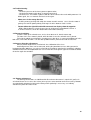
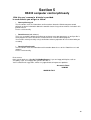
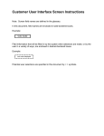
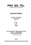
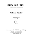
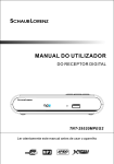
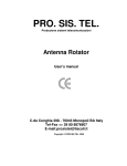
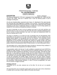
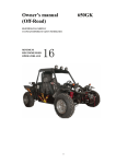
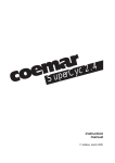
PRO. SIS. TEL.
Produzione sistemi telecomunicazioni
Antenna Rotator
Elevation “D” DC version
User’s manual
Rev.1
C.da Conghia 298 - 70043 Monopoli BA Italy
Tel-Fax ++ 39 80 8876607
E-mail:[email protected]
Copyright @ PRO.SIS.TEL. 2004
Warning
This manual must be read carefully before proceeding to assembly.
Warranty
1) The rotator with the control box, hereinafter called “product”, or “rotator”, is warranted for 2
years from date of purchase, provided that it is supported by the document of sale issued by the
manufacturer or authorized distributor.
2) The warranty covers replacement or repair of any defective component.
3) This warranty does not apply to product which have been subjected to misuse, negligence,
accident, incorrect wiring performed by the user, improper installation or non-compliance to
instructions furnished by us, damage to product which has been repaired or altered without
authorization or to injury or loss resulting from careless maintenance. The warranty does not cover
damage due to transportation and all causes not arising from defects in workmanship.
4) The warranty does not cover costs of transport or insurance for material returned to our
workshops.
5) The manufacturer is not responsible for personal injury or property damage resulting from
improper or careless use of the product.
6) All product is tested after assembly and is supplied without defect. We exclude the
substitution or the prolongation of warranty for a possible damage.
7) After the 2 years warranty period, maintenance or repair will be subject to parts and labor
charges.
8) No person is authorized to assume for us any liability in connection with the sale of our
products.
9) This warranty does not cover damage to people or things due to misuse, improper or
careless installation, or misunderstanding of instructions furnished by us.
10) The right of recession must be exercised in according to the law.
11) Our products are subject to continuous improvement. We reserve the right to implement
improvements and changes without prior notification.
12) The legal code applying in MONOPOLI, Italy, will apply, in cases of dispute.
13) Purchasers of product are deemed to accept paragraphs 1, 2, 3, 4, 5, 6, 7, 8, 9, 10, 11, 12
and 13 as above.
Model:
PST
S/N:
Date of purchase:
2
Important
Read this instruction manual carefully before attempting to operate the antenna rotator.
Save this instruction manual.
This instruction manual contains important safety and operating instruction for antenna rotator.
Precautions
! WARNING, never connect or disconnect rotor cable or RS232 connectors while
power is on. This may results in electrical shock or burn.
Table of contents
Section 1:
Description;
Section 2:
Installation and use;
Section 3:
Principle of operation ;
Section 4:
Technical specifications;
Section 5:
RS232 remote control philosophy;
Table:
Note:
3
Section 1
The controller “D” version
1-1 Front panels description.
1 - POWER SWITCH (POWER)
Turns power ON and OFF
2 – Right lever: CW – UP momentarily switch
Push and hold this switch will activate the rotator clock wise rotation.
Push momentarily while the rotator is running, will stop the rotation.
3 – Left Lever: CCW - DOWN momentarily switch
Push and hold this switch will activate the rotator counter clock wise rotation.
Push momentarily while the rotator is running, will stop the rotation.
4 - Display
Three digit, 7 led bars, will show the rotator degrees bearing.
When turn preset knob, display will show the preset bearing.
The decimal points on the LED display blink when:
• you turn the target position knob on the front panel
• rotation begins and is in progress
• after the end of rotation, while the software waits the programmed time before allowing a new
rotation (if you are using the CW/CCW keys, such a wait time is zero for successive rotations in
the same direction)
5 - Preset rotating encoder
Enables to preset a wanted bearing, just turns the knob, the display will switch on preset function and
will show the encoder position, when the wanted bearing is reach, leaves the knob and after 3 second
the rotor will automatically start and turn to the preset value, as the rotator start, the display will show
the actually rotator bearing.
“Err” is displayed when you turn the target position knob on the front panel to an angle outside the
rotation limits.
4
1-2 Rear panels description.
1 - DB9, RS232 female connector
Enables connectio to a personal computer RS232 serial port, for rotator’s remote operations.
Pin 5 = computer ground
Pin 2 = serial data out (to computer data in)
Pin 3 = serial data in (from computer data out)
2 - Rotator control cable male connector.
Connects the rotator external unit with the controller.
3 – AC Power male socket (230Vac or 115 Vac)
Accept 230Vac or 115Vac throught the AC power cable (check the house’s power before to connect)
4 – Fuse holder.
19x5mm, 1.6A fuse is required.
1-3 “D” Controller features.
Warning:
this is a complex controller, be sure that all functions are well understood before to use it.
This controller has several features settable via RS232 and some of such features are even
settable manually. Four on board dip-switch allows manual selections.
Controller parameters settable in either modes:
•
Soft start – Soft stop
•
South stop or North stop
•
Rotation range 360 or 500 (not used in elevation version)
•
Calibration
•
Off-set
Controller parameters settable via RS232 only:
•
Revers delay
•
Preset delay
•
PWM duty cycles
•
Rotation range (do not use in elevation version)
•
Optimizer (do not use in elevation version)
•
Rotor chk
Controller display mode settable manually only:
•
Absolute or relative display mode.
•
Entering in Absolute mode
The controller uses an ADC which accepts 0-5V voltages. The antenna position voltage readout is
mapped to be inside the 0-5V range. In the absolute mode the display shows directly the rotator
position expressed in absolute degrees: you read values from 0 to 500. In the other operational modes
(north/south-stop) the absolute readings are converted into different angular position numbers, but
only for input/display purposes: internally the program works with absolute angles.
The absolute mode can be only entered turning-on the CBOX with the CW key pressed until the
display shows a blinking “---“ (three minus): now you can release the key and the absolute mode is
entered. You can move the motor using CW and CCW keys between the rotation limits.
To exit from such a mode you must recycle CBOX power (forcing another mode by RS232 command
isn’t effective).
In the absolute mode the rotor can be only operated by the CW/CCW
The absolute mode is usefull for CBOX calibration (see CALIBRATION paragraph).
It is NOT recommended to turn big antennas which need to be started and stopped softly.
5
The bearing values in degree as shown by the display, are not absolute but relative, as show in the
conversion tables:
Vdc
Deg.
000
110
east side
outrange
070
180
S
South stop
absolute values
160
250
340
270
000
090
W
N
E
South stop
Vdc
Deg.
000
290
west side
outrange
070
000
S
500
240
west side
outrange
430
000
S
500
070
east side
outrange
relative values
North stop
absolute values
160
250
340
090
180
270
W
N
E
North stop
430
180
S
relative values
That mean when the Vdc coming from rotor potentiometer is 0V, the display will show 110 deg. when
in South stop (default) and will show 290 deg. when in North stop.
With an applied voltage of 2.50V the display will show 000 deg when in South stop and and 180 deg
when in North stop, while with an applied voltage of 5V the display will show 240 deg. when in South
stop and 070 deg. when in North stop.
•
The on-board dip-switch
There is a on-board dip-switch that allows the user to control a bit the operating mode without the
intervention of a personal computer.
Remember that the dip-switch status is read only at power-up and copied into the EEPROM: you must
recycle the power in order a dip-switch status changement becomes effective.
There are four switches:
•
#1: select the source of the three following parameters: if ON the source is the other three
switches status, otherwise the relative EEPROM contents modifiable through the W command
•
#2: operating mode: if ON is north-stop, otherwise is south-stop
•
#3: rotation range: if ON the rotation range is 0 to 500 absolute degrees, otherwise is 70 to
430 absolute degrees
•
#4: PWM: if ON the PWM is enabled, otherwise is disabled
The above parameters (ENA_PWM, LOWLIM, UPLIM, MODE) are not modifiable by RS232
commands is the switch #1 is ON (dip-switch selected). LOWLIM and UPLIM change accordingly with
the POS_OFFSET values.
•
Soft start and soft stop:
A mosfet controlled PWM is provided, when included it allow to get a soft start and a soft motor stop.
Default valoue: included.
•
South stop or North stop:
Via RS232 or on board dip-switch, it’s possible to switch the display reading mode.
Default valoue: South stop.
•
Rotation range 360 or 500:
500 degrees of rotation range are provided. Such wide rotating range include 70° of extra travel for
each side. In some cases it’s necessary to reduce that rotor’s overrun.
Two modes are provided:
Manually with the on board dip-switch that allow to select between two limits 500 or 360 degrees. Via
RS232, is possible to reduce the rotating range having 1degree step in the range 0-500 degree as well
even the CCW and CW ends. Absolute valoues must to be entered iaw conversion tables.
Default valoue: 0-500 Degrees azimuth, 0-90 elevation
•
Calibration
Two on board trimmers are provided to calibrate the controller.
If necessary, you can recalibrate your controller via RS232. See calibration procedure issue.
6
•
Off-set
If the initial antenna direction it’s not coincident with the geografic direction, you can fix it manually
using an on board off-set trimmer as well via RS232.
Default valoue: 0
•
Revers delay
A reverse delay time is provided to prevent rotor, antennas and tower stress in case of immediate
reversing rotation sense. You can increase or reduce such delay time as you like in consideration of
the antenna dimentions. Suggested/default time: 3 seconds.
•
Preset delay
A preset delay time is provided, it allow you to change the preset valoue several time before than the
rotor start automatically to reach the selected position. Suggested/default time: 3 seconds
•
PWM duty cycles
When included PWM allow to have a soft starting ramp and a soft stopping ramp.
•
Rotation range
This controller allow you to have 500 degrees of total rotor rotation range with 70 degrees of extra
travel for each side. An on board dip switch allow you to choose between two rotations ranges, 0-500
degrees (default) or 0-360 degrees. Do not use in elevation version.
•
Optimizer
When included, if you select a target with Preset knob or via Rs232, the CPU check the shortest way
than will start the rotor following such way. Do not use in elevation version.
•
Rotor chk
When included, if you select a target with Preset knob or via RS232, the CPU check the rotor feed
back signal, if it is not like it have to be, the rotor will be automatically stopped within 5 seconds.
•
Controller internal view
7
•
Calibration procedure.
First-time calibration: It is made in factory.
Whenever an realignment is required (using the on-board OFFSET trimmer):
1. Turn the antenna in a well known direction: if there is some disalignment the position readout
differs from the expected one.
2. Regulate the on-board OFFSET trimmer until the readout reach the expected value
1.4 The rotator
The rotor has a structure where a TV disc actuator is used as elevation motor. It push or pull an arm
welded up a mast clamp having 90° of elevation range.
Top
cm 23 - 30
Tubular mast clamp
Front side
Back side
cm 30
UP
cm 67
cm 35
DOWN
Rotor position
on the vertical mast
30 cm or more
TV disc jack
Azimuth mast
Bottom
8
Section 2
Installation and connections
2.1 Unpacking
After unpacking, immediately report any damage to the delivering carrier or dealer.
Keep the shipping cartoon.
2.2 Power supply connection
Connect the power cable and switch power on, display will show PHH. Switch power OFF.
2.3 Rotator control cable preparation & connection
Before installing the rotator inside a tower, you need to prepare male connector for remote
control cable, make all connections and test rotator operation throughly on the ground, as described
below.
Connect the rotator and control box with a 5-core control cable. Two cores are used for the
motor DC power supply, and three for the position reading potentiometer. If the diameter of the control
cable is too thin, it will limit the voltage and reduce the torque.
Do not use cable with less than 0.5 mm² of section area.
Before connecting rotator and controller, make sure that power switch is OFF.
Cable plug
Wire no. 1
Wire no. 2
Wire no. 3
Wire no. 4
Wire no. 5
Motor terminals board
must be connected to
must be connected to
must be connected to
must be connected to
must be connected to
1 (VDC motor power) >= 1mm²
2 (VDC motor power) >= 1mm²
3 (P to pot central lead)
4 (+5 Vdc pot lead)
5 (0 Vdc pot lead/GROUND)
Warning: Improper wiring can result in damage to the rotator
circuitry when the power is swiched on.
THIS IS NOT COVERED BY THE WARRANTY.
2.4 Rotator cable inspection
Carefully check that the rotator cable connections are as they should be before to connect the
controller.
To check the rotor cable you need a digital multimeter.
Rotator cable true table (either valid for motor board and rotor control cable connector end).
Pins 1 and 2 (internal DC motor resistence = ~ 19 ohm)
Pin 1 and ground = open
Pin 2 and ground = open
Pin 3 and 5 = ~2K (mobile pot end and negative pot end)
Pin 3 and 4 = ~8K (positive pot ends and mobile pot end)
Pin 4 and 5 = 10K (pot ends)
If you did not get such values, check the cable connections ends.
2.5 Preinstallation check
! Warning, use only CW and CCW switch while preinstallation check is in progress.
Switch power ON, display will show PHH and after than the rotator position.
Push the direction lever in CW sense and jack will push up the tubular clamp arm, the display
will follow the rotation and will show increasing positive valoue in degrees. Revers the lever in CCW
sense, and the jack will pull the tubular clamp arm. The display will follow the rotation and will show
decreasing valoue.
To become familiar with the rotor, do some test CW/UP and CCW/DOWN, ceck the travel
limits, they should be: CCW/DOWN +- -000 and CW/UP +- 090.
9
2.6 Troubleshooting
- Power
- Check the presence of the house power at power outlet;
- Check that the power cable plugs is correctly connected.
- Check the fuse. If it’s blown, replace it with one of the correct value and switch power on. If it
blows again, the user contacts the local service agent.
-
Motor turns in the wrong direction
- If while you were pushing CW switch the rotator started in counter sense, than the motor is
getting reversed DC power polarity. Exchange the wires between leads 1 and 2.
-
Rotator follow the right CW and CCW commands but display show the opposite.
- With a digital voltmeter, check the presence of +5Vdc on the motor board, lead no. 4
If +5Vdc is not there, check the rotator cable connections/continuity.
2.7 Rotator installation
Install the rotor up the azimuth mast, no less then 30cm or 1ft from the tower top.
The front side is were motor is placed, while the back is were the azimuth mast is placed.
Fit inside the tubular mast clamp the elevation mast, after when is centered and balanced in the
both sides, lock it with the bolts. Turn the rotor up 000 and then procede to install the antennas.
2.8 Antenna direction adjustement
Antenna rotator alignement is mechanical. See Calibration Offset issue.
Small allignement errors can be corrected, turning the potentiometer case, bring antenna in
horizontal position (000) than just release a little bit the metal belt, switch on the controller in absolute
condition and turn the round potentiometer case to read 25.0, than tighten again the metal belt. Swicth
off and on again the controller.
2.9 Rotator maintenance
The worm-geared motors are lubrificated for life and no maintenance is required. If you live in
an industrial zone or sea area, after a time you may have some corrosion to the outer casing. Rotators
are coated with anticorrosive paint at the factory and if repainting is necessary, use ordinary
anticorrosive paint for ferrous metal.
10
Section 3
Principles of operation
3.1 Electrical configuration
3.1.1 Indicator circuit
Three digit, 7 segments led display are used for the direction indicator and the antenna direction
is displayed in degrees.
3.1.2 Motor power switch
The motor is powered throught two 10 Amps long life relais.
AC
FILTER
POWER
SUPPLY
115V 60Hz
0-42Vac
230V 50Hz
0-12Vac
TRANSF
0-9Vac
CPU
INPUT
1 +
DC
MOTOR
POWER
M
DISPLAY
2 -
4 +5VDC
CW
CCW
ENCODER
3 P
POT.
GND
RS232
PRO.SIS.TEL.
C.da Conghia 298
70043 Monopoli BA
tel.- fax ++39 80 8876607
www.prosistel.it
DRAW: PST61DC, working basic block scheme
S/N: A005
REV: 1
DRAWN BY: Capitanio Piero
DATE: December, 15/2003
Note:
All controllers have the same circuit board, and the same circuit drawing.
Azimuth or elevation version depend only from software setup.
11
Section 4
Rotators Specifications
CARATTERISTICHE
METRICS
PST75-12
PST75-18
PST75-24
Antenna wind area
1.2 m2
2.5 m2
4.5 m2
Elevation range
92°
92°
92°
Static load
250Kg
460Kg
600kg
Dinamic load
150Kg
250kg
300Kg
Maximum mast diameter
53mm
53mm
As request
Rotore weight Kg
8
10
—
US/UK
CARATTERISTICHE
PST75-12
PST75-18
PST75-24
Antenna wind area
12 sq.ft
25 sq.ft
45 sq.ft
Elevation range
92°
92°
92°
Static load
550 lbs
1000 lbs
1320 lbs
Dinamic load
330 lbs
550 lbs
660 lbs
Maximum mast diameter
2.5 inchs
2.5 inch
As request
Rotor weight lbs
17
22
__
12
Section 5
RS232 computer control philosofy
With this user’s manual a diskette is provided.
In such diskette you will get as follow:
• RS232 philosofy.pdf
This file contain extensive informations and instructions about the RS232 computer control
philosofy and more information about the controller features larger than of what is included in this
printed manual.
Please read it carefully.
• RotorVxxx.exe (tool software)
This is an executable software that allow you to change your rotor parameters as well you like it.
Such program have to be intended as a tool and not as a remote control program.
You must be extremly carefully using it and before to do any operation be sure to know what you
are doing.
• RotorVxxxReadme.pdf
This file contain extensive information and instruction about the use of the “RotorVxxx.exe” tool
software.
Please read it carefully.
Dear custmer,
thank you for purchase a Pro.Sis.Tel./BigBoyRotators, if you are happy with it please talk to
everybody, if you are unhappy with it please talk with us.
Your feed back and suggestions, will be very appreciated, to improve our products.
Annamaria Fiume
IK7MWR
MADE IN ITALY
13