1
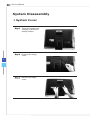
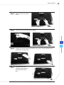
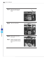
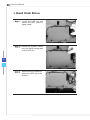
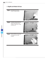
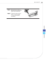
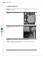
AE221 Series All-in-One (AIO) PC MS-AC95 System G52-AC911X Service Manual Getting Started Important All information is subject to change without prior notice. How to Use this Service Manual This Service Manual is targeted for MSI-authorized dealer or service center. It provides in-depth illustration of disassembling the system. Each topic may be related with each other; hence you are highly recommended to read this guide from cover to cover first. After that, you may go directly to any specific topic that most meets your immediate needs. Necessary Tools A Phillips (crosshead) screwdriver and a flathead screwdriver, can be used to do most of the installation. Choose one with a magnetic head would be better. Pliers, can be used as an auxiliary tool to connect some connectors or cables. Forceps, can be used to pick up tiny screws or set up the jumpers. Rubber gloves, can prevent yourself from being incised and suffering the static charge. Safety Precautions The following precautions should be observed while handling the system: ■ Place the system on a flat and stable surface. ■ Do not place the system in environments subject to mist, smoke, vibration, excessive dust, salty or greasy air, or other corrosive gases and fumes. ■ Do not drop or jolt the system. All-in-One PC ■ Do not bump or knock the LCD screen as it is fragile and could break. ■ Do not use another power adapter other than the one enclosed with the system. ■ Disconnect the AC/DC adapter before performing any installation procedures on the system. ■ Do not perform any maintenance with wet hands. ■ Prevent foreign substances, such as water, other liquids or chemicals, from entering the system while performing installation procedures on the system. ■ Use a grounded wrist strap before handling system components such as CPU, Memory, HDD, mini PCI-E card, etc. ■ Place system components on a grounded antistatic pad or on the bed that came with the components whenever the components are separated from the system. ■ If there are any difficulties installing hardware devices, please contact MSI for further information. Other Notice ■ The peripheral devices contained herein may vary depending on your actual system configuration. ■ Third-party trademarks and names are the properties of their respective owners. ■ The information contained herein relevant to software and hardware are for reference only and in accordance with actual system configuration. All information is subject to change without notice. Upgrade and Warranty Please note that certain components preinstalled in the product users purchased may be upgradable or replaceable by user’s request. To learn more about upgrade limitation, please refer to the specification in the User’s Manual. For any further information about the product users purchased, please contact the local dealer. Do not attempt to upgrade or replace any component of the product, if you are not an authorized dealer or service center, since it may cause the warranty void. It is strongly recommended that you contact the authorized dealer or service center for any upgrade or replace service. Acquisition of Replaceable Parts Please be noticed that the acquisition of replaceable parts (or compatible ones) of the product users purchased in certain countries or territories may be fulfilled by the manufacturer within 5 years at most since the product has been discontinued, depending on the official regulations declared at the time. Please contact the manufacturer via http://www.msicomputer.com/msi_user/msi_rma/ for the detailed information about the acquisition of spare parts. Important The system photos are provided for demonstration of system disassembly only. The internal view of your system may vary depending on the model you purchased. Service Manual System Disassembly System Cover Step 1. Place the system horizontally on a flat and steady surface. Step 2. Unscrew the hinge cover. Step 3. Remove the hinge cover. All-in-One PC Step 4. Remove the foot stand cover. Step 5. Unscrew and remove the foot stand. Step 6. Locate the screws that secure the rear cover. Unscrew them and keep them for later use. Step 7. Pull the rear cover carefully upwards and set it aside for later use. Service Manual Step 8. Under the rear cover is a metal shield provided to secure and protect the system components. Locate the screws that secure the metal shield. Remove the screws and the metal shield and keep them for later use. Important Before you remove or install any components, make sure the system is not turned on or connected to the AC power. All-in-One PC CPU Step 1. Locate the cooler set and the screws that attach the cooler set to the mainboard. Remove the screws in a diagonal sequence and set the screws aside for later use. Step 2. Disconnect the fan power connector. (GPU Model) (UMA Model) Step 3. Remove the cooler set to uncover the CPU. (GPU Model) (UMA Model) Service Manual Step 4. Open the load lever and lift it up to a 90-degree angle. Step 5. Open the load plate. Step 6. Remove the CPU from the socket. Step 7. Follow the above procedures in reverse order to replace the CPU if necessary. All-in-One PC Memory Step 1. Locate the SO-DIMM slot. Step 2. Flip the slot clips outwards and the DIMM will spring upwards instantly. Step 3. To avoid damaging the golden finger, remove the DIMM at the same angle it was inserted. Important To reinstall the DIMM, you should: 1. Align the notch on the DIMM with the key on the slot and insert the DIMM into the slot at a 45-degree angle. 2. Push the DIMM gently downwards until the slot clips click and lock the DIMM in place. Service Manual Hard Disk Drive Step 1. Locate the HDD set and detach the HDD power & signal cable. Step 2. Detach the system cables from the cable routing tabs on the HDD set. 10 Step 3. Remove the screws that attach the HDD set to the chassis. All-in-One PC Step 4. Lift up the HDD set to release it from the system chassis. Step 5. Unscrew the HDD and pull it out from the HDD tray. Step 6. Follow the above procedures in reverse order to replace the HDD if necessary. 11 Service Manual Optical Disk Drive Step 1. Disconnect the ODD power & signal cable. Step 2. Unfasten the screws that secure the ODD to the chassis. Keep the screws for later use. 12 Step 3. Lift the ODD set upwards to release it from the chassis. All-in-One PC Step 4. Remove the screws on the ODD set and take the ODD out from the tray. Step 5. Follow the above procedures in reverse order to replace the ODD if necessary. 13 Service Manual CMOS Battery NOTE: Make sure that you write down the CMOS settings before removing the CMOS battery. Step 1. Locate the CMOS battery. Step 2. Disconnect its cable. 14 Step 3. Detach the battery sticker to release the battery. Step 4. Replace only with the same or equivalent type of battery recommended by the manufacturer.