1
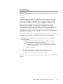
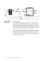
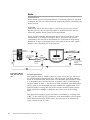
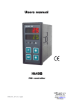
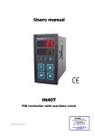
Series 988
Enhanced Software Features
Includes 986, 987, 988 and 989
1/8 DIN Microprocessor-Based Temperature/Process Controller
Watlow Controls
1241 Bundy Boulevard, P.O. Box 5580, Winona, Minnesota USA 55987-5580
Phone: (507) 454-5300, Fax: (507) 452-4507 http://www.watlow.com
Table of Contents
Cascade . . . . . . . . . . . . . . . . . . . . . . . .3
Differential . . . . . . . . . . . . . . . . . . . . . .7
Dual PID . . . . . . . . . . . . . . . . . . . . . . . .9
Duplex . . . . . . . . . . . . . . . . . . . . . . . .11
Ratio . . . . . . . . . . . . . . . . . . . . . . . . . .12
Technical Assistance
If you encounter a problem with your Watlow controller, review all of your
configuration information for each step of the setup to verify that your
selections are consistent with your applications.
If the problem persists, an Application Engineer can discuss your
application with you.
Before calling, please have the complete model number and user’s manual
available. You can get technical support by dialing 507/494-5656, 7 a.m.
to 7 p.m. Central Standard Time, or e-mail to [email protected].
We Value Your Feedback
Your comments and suggestions on this manual are welcome. Please send
them to, Technical Writer, Watlow Controls, P.O. Box 5580, Winona, MN
55987-5580, or call (507) 454-5300, or fax (507) 452-4507. The Series
988 Advanced Software Features manual is copyrighted by Watlow
Winona, Inc., © October 1999, with all rights reserved. (1859)
2
WATLOW Series 988 Enhanced Software Features
Cascade
Requirements
Cascade control requires enhanced software and two analog inputs, input
1 to monitor the primary, or outer, loop and input 2 to monitor the
secondary, or inner, loop. At least one control output is required to control
the process.
Overview
Cascade control can handle a difficult process with minimal overshoot,
while reaching the set point quickly. This minimizes damage to system
components and allows for oversizing heaters for optimal heat-up rates.
Heater life is also extended by reducing thermal cycling of the heater.
Systems with long lag times between the energy source (heater, steam,
etc.) and the measured process value cannot be controlled accurately or
efficiently with a single control loop, because a lot of energy can build up
before a response is detected. This
can cause the system to overshoot
the set point, which could damage
the heater, product or heat transfer
medium, such as a heat transfer
fluid.
Figure 9.3a - System
heat-up profiles
using three different
control methods.
Figure 9.3b - The
cascade feature
allows one Series
988 controller to
internalize the functions of two controllers.
This graph illustrates a system with
a long lag time. Curve A represents
a single-control system with PID
parameters that allow a maximum
heat-up rate. Too much energy is
introduced and the set point is overshot. In most long-lag-time systems the process value may never settle out
to an acceptable error. Curve C represents a single-control system tuned
to minimize overshoot. This results in unacceptable heat-up rates, with
the final value taking hours to reach. Curve B shows a cascade system
that limits the energy
introduced into the system,
allowing an optimal heatup rate with minimal overshoot.
This drawing shows two
controllers configured as a
cascade system. The
second controller generates
the internal set point. The
Series 988 effectively
combines both controllers into a single package.
The primary controller measures the process in the outer, or primary, loop
with input 1 and compares the value to the desired set point. The
WATLOW Series 988 Enhanced Software Features
3
difference between the set point and the process temperature generates an
internal percent output value for the second, or inner loop, controller. This
value cannot be seen by the operator. This internal percent (% int) output
generates the internal set point for the secondary, or inner loop. The
secondary loop uses this set point and the value of input 2 (typically
attached to the heater sheath) to control the heat source temperature.
Algorithm
The following formulas show how the primary control sends a set point
(based on input 2 range-high and range-low values) to the secondary control. The secondary control uses this set point (SP int) to generate a
percent output (% out) to the heater.
1.) %int = PID Set A [In1 - SP]
2.) SPint = (rH2 - rL2) * %int + rL2
3.) %out = PID Set B [In2 - SPint]
The critical parameters are the range settings for input 2 of the inner loop
controller. The range-high value (rH2) is the maximum allowed set point
for the secondary, or inner, loop. The range-low value (rL2) is the minimum allowed set point. In a system controlling a heater this would be the
maximum and minimum desired sheath temperatures of the heater.
Typically the range-low term is set below the ambient temperature.
Otherwise the system could never fully cool down.
Setup
When tuning a cascade system, the inner loop must be tuned first. In a
heating system the inner loop is comprised of the output device and the
input 2 sensor, which usually measures the heater sheath temperature.
The output device controls a power switching device, which, in turn
switches the heater. The set point for the inner loop is generated by the
outer loop and will have a range between range low 2 [`rL2] and range
high 2 [`rH2].
Before tuning the inner loop you must make sure [`rL2] and [`rH2] are
set properly. Set the value of [`rL2] slightly lower than the ambient temperature, otherwise the system will never fully cool down. Set [`rH2] to
the maximum desired heat source temperature. The inner loop can be
auto-tuned by setting [`AUt] to [Pidb]. While auto-tuning, the inner loop
will be controlled in an ON/OFF mode at a set point equal to [AtSP] x
[`rH2].
Once the inner loop, PID B, has completed auto-tuning, we can then autotune the outer loop, PID A. The outer loop will generate the set point for
the inner loop. This is done by comparing the value of the input 1 sensor
to the process set point, performing the control algorithm by using the
values of [PidA], then generating a set point between [`rL2] and [`rH2].
4
WATLOW Series 988 Enhanced Software Features
The outer loop can be auto-tuned by setting [`AUt] to [PidA]. While autotuning, the outer loop will be controlled in an on/off mode at a set point
equal to [AtSP] x [`SP1]. In a heating application, make sure the set
point is set at a value above ambient temperature. In most cases, the
auto-tuning feature will tune [PidA] for acceptable control. If not, you
must then manually tune the outer loop.
Before beginning manual tuning, record the values of [Pb1A] and [rE1A]
generated by the auto-tuning feature. The auto-tune for the outer loop will
not generate a value for [rA1A], because rate (derivative) in the outer loop
seems to cause instability in most systems.
Start manual tuning by setting [rE1A] to [`)00]. Enter the desired
process set point and let the system stabilize. Once the system stabilizes,
observe the value of [`Pr2] in the Display Menu. If the [`Pr2] value
fluctuates, make the proportional band setting [Pb1A] wider until the
[`Pr2] value stabilizes. Make adjustment [Pb1A] in 5° to 10° increments,
allowing time between adjustments for the system to stabilize.
Once [`Pr2] has stabilized, observe percent power in the display loop. It
should be stable, ±10%. At this point, the process temperature should also
be stable, but will exhibit droop (stabilized below set point). The droop can
be eliminated with reset of integral.
Start with a setting of 0.01; allow 10 minutes for the process temperature
to come up to set point. If it has not, increase the setting to 0.05 and wait
another 10 minutes. After this, double the reset setting until process value
equals the set point. If the process becomes unstable, the reset value is
too large. Decrease the setting until the process stabilizes.
WATLOW Series 988 Enhanced Software Features
5
Figure 9.6 - Lube oil
tank with cascade
control.
Sample Application
A Series 988 controller is used to heat lube oil to 125°F with a screw-plugstyle heater. To protect the oil from breaking down and maximize its life, it
is desirable to limit the maximum heater sheath temperature to 250° F.
The Series 988 is ordered with two thermocouple inputs. Input 2, the
inner loop in the cascade configuration, measures the heater sheath.
Input 1, the outer loop, measures the lube oil temperature before it leaves
the tank. The external set point is 125°. By setting range high 2 [`rH2] to
250° the set point for the heater sheath will be limited, thus extending the
lube oil life.
6
WATLOW Series 988 Enhanced Software Features
Differential
Requirements
Two inputs and the enhanced software option are required.
Overview
Differential control allows the Series 988 to control one process at a
difference to another process. Input 2 acts as a remote set point input.
However the displayed set point indicates the desired difference between
input 1 and input 2. The set point that input 1 will use is determined by
the equation:
internal set point = input 2 + differential set point
The lower display shows the differential set point, which can be adjusted
with the increment (up-arrow) and decrement (down-arrow) keys.
Please note that while in the differential control mode the internal set
point for input 1 cannot be viewed and must be calculated with the
equation.
WATLOW Series 988 Enhanced Software Features
7
Figure 9.8 - Freezer
display case with
differential control.
Sample Application
An application using differential control is to maintain glass temperature
of a freezer display case above dew point at a differential to the ambient
air temperature. A thermocouple at input 2 senses the outside air temperature and adjusts the internal set point to maintain the glass temperature
10 degrees higher. Substituting values we have: glass temperature =
ambient + 10°.
In this application the system uses two type J thermocouples: one to
sense glass temperature (input 1) and one to sense the ambient air temperature (input 2).
To configure the controller, first enable input 2 (set
to
). To
enable the differential control algorithm set the control prompt
in
the Global Menu to differential
. Press the DISPLAY key. The lower
display will read 0, indicating no differential between input 1 and input 2.
Adjust the set point to 10. The internal set point for input 1 is now equal
to the input 2 value plus 10, which will maintain the boiler water temperature 10 degrees higher than the outside air temperature.
8
WATLOW Series 988 Enhanced Software Features
Dual PID Sets
Requirements
The Series 988 controller needs the enhanced software option to use dual
PID sets.
Overview
Standard software units have a single set of PID parameters. Units with
enhanced software can use two independent sets of heat/cool PID parameters, PID A [PidA] and PID B [Pidb]. To enable dual PID, enter the
Global Menu and set the algorithm prompt [ALgO] to dual PID [Pid2].
This second set of PID parameters enables the controller to switch
between two sets of PIDs, to compensate for changes in the system
characteristics. This need can arise from a variety of circumstances, such
as significant set point changes (controlling at 250, then controlling at
750), operating a furnace with half a load versus a full load of steel,
changing the speed of a conveyor through a curing oven or using different
materials in an extruder.
Series 988 controllers can be configured to switch between PID A and PID B
based on a process value, a set point value or the event input status.
• At [Pid2] PID 2 Crossover Selection (Global Menu) select what will
cause the switch:
• [Proc] Crossover Process Value, (input 1), PIDs will switch
based on the crossover process value;
• [StPt] Crossover Set Point (1) Value, PIDs will switch at the
crossover set point value, PID A used below the crossover
point and PID B above;
• [``no] no crossover.
• At [`Ei1] Event Input 1 or [`Ei2] Event Input 2 select [`Pid]:
• PID A is used when the event input switch is open;
• PID B when the event input switch is closed.
(Note: One event input is standard on all units, a second event input is an
option.)
WATLOW Series 988 Enhanced Software Features
9
Figure 9.10 - Test
chamber controlled
with dual PID sets.
Sample Application
A test engineer needs to control the temperature in a test chamber that
can be operated at normal atmosphere or under vacuum conditions. If he
tunes the controller for normal atmospheric conditions, when he reaches
the portion of his test that requires a vacuum, he must stop the test and
enter new PID parameters to maintain stable temperatures. The system
characteristics are so very different, that one set of PIDs will not give satisfactory results under both normal and vacuum conditions.
The Series 988 solves this problem with the dual PID option. Auto-tuning
PID A under normal atmospheric conditions, then auto-tuning PID B
under vacuum conditions, establishes PID values for two sets of system
characteristics. A pressure switch connected to the event input tells the
controller when to switch between PID A and PID B, eliminating the need
to change PID values manually.
10
WATLOW Series 988 Enhanced Software Features
Duplex
Requirements
The duplex control feature requires enhanced software and a process output.
NOTE:
Duplex applications
require a special
valve.
Figure 9.11 - Fluid
sample container
with duplex control.
Overview
Certain systems require that a single process output control both heating
and cooling outputs. A Series 988 controller configured with enhanced
software and a process output can function as two separate outputs. With
a 4 to 20mA output the heating output will operate from 12 to 20mA (0 to
+100 percent) and the cooling output will operate from 12 to 4mA (0 to 100 percent). In some cases this type of output is required by the device
that the 988 controls, such as a three-way valve that opens one way with
a 12 to 20mA signal and opens the other way with a 4 to 12mA signal.
This feature reduces the overall system cost by using a single output to
act as two outputs.
Sample Application
The system outlined above uses a three-way valve for heating and cooling
a fluid sample. Coils surround the container holding the fluid. When the
temperature needs to be raised, the signal to the valve will be between 12
and 20mA, sending hot water through the coils. When cooling is required,
the signal will be between 12 and 4mA, sending cold water through the
coils.
WATLOW Series 988 Enhanced Software Features
11
Ratio
Requirements
Ratio control requires enhanced software. Two analog inputs are required
to monitor the process, and at least one output adjusts the controlled part
of the process.
Overview
This feature allows the Series 988 to control one process as a ratio of
another process. This is especially useful in applications that mix two
materials, whether steam, paint or food ingredients.
Input 2 of the controller measures the part of the process that is either
uncontrolled or controlled by another device. The part of the process
controlled by the 988 will be maintained at a level equal to the quantity
measured at input 2 multiplied by the ratio term set by the user. Input 1
monitors the controlled part of the process.
Figure 9.12 - Mixing
tank with ratio control.
Sample Application
Blue pigment must be added to paint at a ratio of one part per 100 to create a mixed paint of the desired color. The uncolored paint flows into the
mixer in an uncontrolled stream that is set manually and sensed by input
2. A motorized valve controls the flow of pigment, which is monitored by
the flow sensor to input 1. The flow rate of the uncolored paint determines
the set point for the motorized valve that controls the pigment flow. If an
operator needs to change the rate of flow for the uncolored paint, the set
point will shift accordingly to maintain the correct ratio in the mixing
tank.
The application engineer set up this feature in software by choosing ratio
[rAti] as the control [CntL] parameter in the Global Menu. The set point
value displayed was then a ratio value. He entered 0.01 to maintain an
input 1:input 2 ratio of 1:100.
12
WATLOW Series 988 Enhanced Software Features