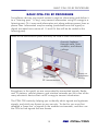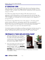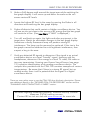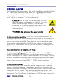
1
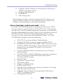
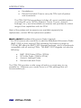
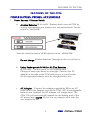
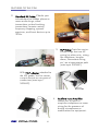
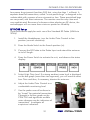
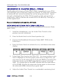
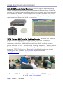
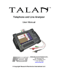
C P M- 7 0 0
COUN
TE
R S U R VEIL
LAN
C E PR
O B E/
*
MON
ITOR
*CPM-700 is available with sev eral optional probes a nd accessories; some of which are
pictured above. This manual addres ses availabl e probes and accessorie s with the CPM-7 00,
however these probes and accessori es are not necessarily included with each CPM-700.
PREC AUTIO N / WARNING !
The overall effectiveness of this product is directly dependent on your familiarization and level
of threat. T his manual is marked * in areas where special a ttention is required.
This manual c ontains proprietary information intended
solely for use with the CPM-700 an d CPM-700 Probes and Accesso ries.
All information contained within this manual
is subject to change withoutnotice.
O WNER’S REC O RD
The Serial Number of your unit is located on the side panel. Please rec ord
this number and refer to it whenever you contact your dealer or Research
Electronics International concerning this product. Note: Removal or
alteration of the serial number automatically voids all warranties of this
product.
MO DEL:
CPM-700
SERIAL NUMBER: ___ _______________
TABLE OF CONTENTS
TABLE OF CONTENTS
INTRODUCTION............................................................. 1
CPM-700 PACK AGES . . . . . . . . . . . . . . . . . . . . . . . . . . . . . . . . . . . . . . . . . . . . . . 2
FEATURES OF THE CPM................................................... 5
POWER SUPP LIES, P ROBES, ACCE SSORIES . . . . . . . . . . . . . . . . . . 5
F RO N T P AN E L F EATUR ES . . . . . . . . . . . . . . . . . . . . . . . . . . . . . . . . . . . . . . . . . 9
AU DI O GROUP . . . . . . . . . . . . . . . . . . . . . . . . . . . . . . . . . . . . . . . . . . . . . . . . . . . . . . 9
MONITOR GROUP . . . . . . . . . . . . . . . . . . . . . . . . . . . . . . . . . . . . . . . . . . . . . . . . . . 9
DISPLAY GROUP . . . . . . . . . . . . . . . . . . . . . . . . . . . . . . . . . . . . . . . . . . . . . . . . . . 1 0
P RO BE GROUP . . . . . . . . . . . . . . . . . . . . . . . . . . . . . . . . . . . . . . . . . . . . . . . . . . . . 1 1
SIDE PANEL FEATURES . . . . . . . . . . . . . . . . . . . . . . . . . . . . . . . . . . . . . . . . . . . 1 1
POWER SOURCES......................................................... 13
A LKA LI NE BA TTE R Y OPE RA TIO N . . . . . . . . . . . . . . . . . . . . . . . . . . . . . .
A C A DAPT ER OPE RAT IO N . . . . . . . . . . . . . . . . . . . . . . . . . . . . . . . . . . . . . .
OP TI O NAL R E CHAR GEA BLE BA T TER Y OP ERA TIO N . . . . . . .
CHARGI NG INSTRUCTIONS . . . . . . . . . . . . . . . . . . . . . . . . . . . . . . . . . . .
13
13
13
13
BASIC CPM-700 RF PROCEDURE.................................... 15
R F C O NSI DE RA TI O N S . . . . . . . . . . . . . . . . . . . . . . . . . . . . . . . . . . . . . . . . . . . 1 6
PE RFO RMING A “ WALK A ROU ND R OOM SWEEP” . . . . . . . 1 6
DETAILED CPM-700 PROCEDURE................................... 19
ME TE R CA LI BRATION . . . . . . . . . . . . . . . . . . . . . . . . . . . . . . . . . . . . . . . . . . . .
K NOW N SOU ND S OU RC E . . . . . . . . . . . . . . . . . . . . . . . . . . . . . . . . . . . . .
R F P R OBE A NA LY SI S . . . . . . . . . . . . . . . . . . . . . . . . . . . . . . . . . . . . . . . . . . . . .
B R OA D BA ND RF A NA LY S IS ( 2 GHZ – 1 2 GHZ) . . . . . . . . . . . . .
DETAILED INSPE CTI ON SWEEP . . . . . . . . . . . . . . . . . . . . . . . . . . . . . . . .
P HONE / LI NE RF SWEEP . . . . . . . . . . . . . . . . . . . . . . . . . . . . . . . . . . . . . . . . .
T RA CK I NG D E V I C E S . . . . . . . . . . . . . . . . . . . . . . . . . . . . . . . . . . . . . . . . . . . . . .
V LF P R O BE . . . . . . . . . . . . . . . . . . . . . . . . . . . . . . . . . . . . . . . . . . . . . . . . . . . . . . . . . .
AU DI O TE STI NG . . . . . . . . . . . . . . . . . . . . . . . . . . . . . . . . . . . . . . . . . . . . . . . . . .
MI SC. WIRE / AU DI O EVALUA TI ON . . . . . . . . . . . . . . . . . . . . . . . . . .
19
19
20
22
24
25
26
27
29
30
PLANNING AND CONDUCTING A SWEEP...................... 31
SWEEP P REPA RA TION . . . . . . . . . . . . . . . . . . . . . . . . . . . . . . . . . . . . . . . . . . . .
E ST AB LI S H A “ GAME P L A N” . . . . . . . . . . . . . . . . . . . . . . . . . . . . . . . . . . . .
SWEEP TIPS . . . . . . . . . . . . . . . . . . . . . . . . . . . . . . . . . . . . . . . . . . . . . . . . . . . . . . . . .
P HY SI CA L SEA R C H . . . . . . . . . . . . . . . . . . . . . . . . . . . . . . . . . . . . . . . . . . . . . . . .
i
31
31
32
34
REI CPM-700
TABLE OF CONTENTS
OTHER PROCEDURES AND EQUIPMENT ........................ 37
SPECIFICATIONS........................................................... 41
WARNINGS .................................................................. 45
TSCM TRAINING
REI Center for Technical Security: REI offers the World’s largest unclassified
commercially available Technical Surveillance Countermeasure (TSCM)
training facility. Training courses include classroom instruction and handson exercises where students perform sweep exercises in “live” environments
utilizing “target rich” project rooms. The progressive course curriculum is
designed for the beginner or the seasoned TSCM Technician. Regularly
scheduled courses are taught monthly; visit REI’s website (www.reiusa.net)
or contact REI ([email protected]) for training dates.
Contact REI for more information TSCM training and/or other
TSCM equipment visit www.reiusa.net.
REI CPM-700
ii
INTRODUCTION
INTRODUCTION
The CPM-700 Countersurveillance Probe/Monitor is a universal sweep tool
that can be used to detect and locate a wide variety of surveillance devices.
A broad range of probes and accessories are available for the CPM-700 to
expand the CPM’s countersurveillance capabilities.
NOTE: Depending on the CPM-700 package purchased, and/or
additional probes purchased, you may or may not have all the
probes and accessories discussed in this manual.
The CPM-700 detects and locates transmitting devices, quickly and silently,
including:
• AF (Audio Frequency)……...100 Hz to 15 kHz.
• VLF (Very Low Frequency)….15 kHz to 1 MHz and carrier current
• RF (Radio Frequency...……..50 kHz to 3 GHz
With the additional probes and accessories, the CPM can detect and
locate:
• High Frequency transmitters (3 - 12 GHz, such as 802.11 wireless
networks and 5.8 GHz cordless telephones, with BMP-1200)
• Infrared transmitters (with IRP-700)
• Magnetic Leakage (with MLP-700)
• Acoustic Leakage vulnerability (with ALP-700)
Special Note
The overall effectiveness of any technical surveillance
countermeasure is directly dependent on the level of threat and the
users ability to properly deploy the appropriate countermeasure.
Familiarization with the level of threat, the physical and technical
environment, and most importantly the capabilities of the CPM700 is critical to using the CPM-700 successfully. The
manufacturer makes no guarantee about the performance of the
unit when attempting to detect hidden electronic devices. It may
be necessary to employ other supplementary equipment and/or
procedures. REI’s Center for Technical Security offers training on
technical surveillance countermeasure equipment.
The section “Planning and Conducting a Sweep” contains many
practical tips for getting the most out of your CPM and other
countersurveillance equipment.
1
REI CPM-700
INTRODUCTION
CPM-700 PACKAGES
Several probes and accessories (some of which are optional) are available
for the CPM-700. Many of these probes and accessories are available
separately, but also in the packages listed below:
CPM-700 STANDARD
The CPM-700 STANDARD package provides the basic tools for
users who are only concerned with minimal RF testing; the CPM700 STANDARD package includes the following:
•
•
•
•
•
•
•
CPM-700 Countersurveillance Probe/Monitor
Standard RF Probe (50kHz-3GHz)
VLF Carrier Current Probe
TVLF Patch Cable
Auxiliary Patch Cable
Headphones
Soft carrying case
This is the most basic package providing for TSCM RF testing up to
3GHz.
CPM-700 ADVANCED PACKAGE
The CPM-700 ADVANCED package is designed for users who
have a need for additional TSCM testing (IR, Acoustic Leakage,
Network and Telephone wiring testing, etc.). This package also
provides several convenience accessories and includes the
following:
•
•
•
•
•
•
•
•
•
•
CPM-700 Countersurveillance Probe/Monitor
Standard RF Probe (50kHz-3GHz)
Acoustic Leakage Probe
Infrared Probe
VLF Carrier Current Probe
TVLF Patch Cable
Magnetic Leakage Probe
Auxiliary Patch Cable
Modular Phone Adapter for network and phone line
testing
Tape Recorder Patch Cords
REI CPM-700
2
INTRODUCTION
•
•
•
•
Cigarette Lighter Adapter for powering the CPM from a
12VDC automobile socket
Rechargeable Batteries
Headphones
Soft carrying case
This package includes several accessories for RF analysis up to
3GHz, Infrared analysis, acoustic leakage testing, network and
telephone testing adaptors, and other accessories.
(12GHz)
The CPM-700 DELUXE package is designed for the serious TSCM
user who wants to get the most out of the CPM-700. This package
includes all currently available probes and accessories, including the
directional Broadband Microwave Probe, which extends the range of
the CPM-700 to 12GHz and adds additional sensitivity in the
common 2.4 GHz range over the Standard RF Probe. The CPM700 DELUXE package includes the following:
CPM-700 DELUXE PACKAGE
•
•
•
•
•
•
•
•
•
•
•
•
•
•
CPM-700 Countersurveillance Probe/Monitor
Standard RF Probe, frequency range of 50kHz-3GHz
Broadband Microwave Probe (BMP-1200), frequency range
of 2GHz-12GHz (This probe is directional and much more
sensitive than the standard RF probe in the common
2.4GHz range.)
Acoustic Leakage Probe for evaluating structural bound
audio leakage
RF Sniffer Probe (10MHz-3GHz) for pinpointing surveillance
devices where the Standard RF Probe may become
saturated with RF energy
Infrared Probe
VLF Carrier Current Probe
TVLF Patch Cable
Magnetic Leakage Probe
Auxiliary Patch Cord
Modular Phone Adapter for network and phone line testing
Tape Recorder Patch Cords
Cigarette Lighter Adapter for powering the CPM from a
12VDC automobile socket
Rechargeable Batteries
3
REI CPM-700
INTRODUCTION
•
•
Headphones
Deluxe Hard-shell Case to carry the CPM and all probes
and accessories
The CPM-700 Deluxe package includes all current available probes
(including RF up to 12GHz, Infrared, Carrier Current, Acoustic
Leakage, etc.), and all available accessories and provides the widest
range of test capabilities with the CPM.
Most of the probes and accessories are available separately for
replacement; contact REI for replacement probes.
Broadband Microwave Probe Upgrade
For CPM owners who would like to add the Broadband Microwave Probe
(BMP-1200) to their existing CPM (extending the frequency range to
12GHz), REI offers the BMP-1200 Upgrade package, which is backwards
compatible with all existing CPMs. The BMP-1200 Upgrade includes the
following:
BMP-1200
•
•
•
•
BMP-1200 Probe (2GHz-12GHz)
RF Sniffer Probe (10MHz-3GHz)
Acoustic Leakage Probe
Deluxe Hard-shell Case
The CPM-700 provides a wide range of tools in a single easy-to-use
portable kit. Whatever your needs, there is a CPM package that will
accommodate you.
REI CPM-700
4
FEATURES OF THE CPM
FEATURES OF THE CPM
POWER SUPPLIES, PROBES, ACCESSORIES
1. Power Sources / Selector Switch:
a. Alkaline Batteries (8 AA cells) - Remove back cover of CPM by
turning two fasteners one-quarter turn counterclockwise. Set the
switch to “ALKALINE.”
Selector switch in back of CPM is factory set to “ALKALINE”
Do not charge Alkaline batteries. Damage to the unit will occur.
b. Using Rechargeable Ni-MH or Ni-Cad Batteries
(8 AA cells) – Set the switch to “RECHARGEABLE.”
Charge at least eight hours or overnight. Connect the AC
adapter to the side of the CPM and plug in to a wall outlet.
All rechargeable batteries must be charged before use.
c.
AC Adaptor – Connect the adapter supplied by REI to an AC
outlet and to the Adapter input of the CPM-700. If rechargeable
batteries are installed, the AC adapter will charge them. The
CPM-700 will automatically operate on the battery pack if the
AC power fails. NOTE: Do not use any adapter other than the
one supplied by REI.
5
REI CPM-700
FEATURES OF THE CPM
2. Standard RF Probe: Checks your
environment for hidden phone or
room-audio bugs; video
transmitters; pulsed tracking
transmitters; remote control,
frequency-hopping, spreadspectrum, and burst devices up to
3GHz.
3. VLF Probe: Tests for carriercurrent bugs that use AC
wiring (or other misc. wiring
like telephone, burglar
alarm, thermostat wiring,
etc.) as a transmission path
(max input 300VAC).
With TVLF adapter attached to
the VLF probe, test for carrier
current devices on any pair of
conductors (max input
300VAC).
4. Auxiliary Input Amplifier:
Allows you to listen to
suspicious telephone or room
wiring for the presence of
buried microphones or
modifications to equipment.
REI CPM-700
6
FEATURES OF THE CPM
5. BMP-1200 Broadband
Microwave Probe: Receives RF
energy between 2GHz and
12GHz, including frequencies
used for wireless networks and
many cordless telephones.
6. RF “Sniffer” Probe: Helps to isolate
‘threat’ transmissions from
legitimate broadcast transmissions
in RF-rich environments up to
3GHz. Must check within 18” of
every object in the target area.
7. IRP-700 Infrared Probe: Locates
infrared transmissions.
8. MLP-700 Magnetic Leakage Probe:
Locates carrier current devices, tape
recorders and video cameras.
7
REI CPM-700
FEATURES OF THE CPM
9. MPA Modular Phone Adaptor: Rapidly tests each pair of conductors in
telephone and network cables or carrier current or audio transmissions
Testing for carrier
current devices
Testing for line
audio
Modular Phone
Adapter (MPA)
Cable from
telephone
TVLF Adaptor
Auxiliary Patch
Cable
VLF Probe
To CPM
To CPM
10. TVLF Adaptor: Adapts VLF Probe to check any kind of wiring (not just
wall outlets) for carrier current devices (see above).
11. ALP-700 Acoustic Leakage
Probe: Detects and evaluates
areas vulnerable to acoustic
leakage. (Also used with testing
of REI’s ANG 2200 – Acoustic
Noise Masking System.)
12. NCB: Rechargeable battery pack, 8 Ni-MH cells, size AA
13. CLA: 12 VDC automotive cigarette lighter adapter
REI CPM-700
8
FEATURES OF THE CPM
FRONT PANEL FEATURES
1
2
6
3
7
4
8
5
9
10
11
12
AUDIO GROUP
PHONES (1): Allows the use of silent headphone detection, disconnects the
internal speaker.
GAIN (2): Controls the Audio Gain (volume) to the speaker or Headphone
Output. Does not affect Record Out level.
FILTER (3): The audio Filter will “band-pass” the audio
response for voice levels by enhancing the 500 Hz to 2.5 kHz
frequencies. The Filter also removes much of the AC hum on
the Auxiliary Input, or video hum when using the RF Probe
Input. The Filter processes the audio for both the headphones and the
record-out jack. Display shows whether filter is IN or OUT.
MONITOR GROUP
MODE (4): Sets the unit to its Search or Monitor function.
The SEARCH mode is used for performing a sweep. The
MONITOR mode is used after a sweep to check continually
for new devices. Display shows whether Mode is SEARCH or
MONITOR
With the CPM in MONITOR mode, a new signal stronger than the
THRESHOLD level (see below) will cause the ALERT LED to flash, and the
CPM will make an audible TONE.
9
REI CPM-700
FEATURES OF THE CPM
The remaining functions in this group are active only while in the MONITOR mode:
SILENT/TONE (5): Silences the audible beeper during an
ALERT. The LED will continue to flash. Display shows whether
CPM is in TONE or SILENT mode.
THRESHOLD (6): Moves a pulsing segment to any position on the LCD Bar
graph. When the input level exceeds the pulsing segment, the CPM-700
enters an Alert Mode and activates the Remote Output.
The THRESHOLD control is active only in the MONITOR mode.
ALERT (7): LED flashes red while in ALERT mode.
DISPLAY GROUP
INPUT LEVEL (8): Bar graph indicates signal strength of Probe or Auxiliary
Inputs; compressed semi-logarithmic with two sensitivity scales.
PULSING SEGMENT (9): In MONITOR mode only, displays the Threshold
Point that will activate the Alert mode and Remote Output.
LOW BATT (not shown): Battery voltage indicator; indicates approximately
10% remaining power.
STATUS DISPLAY (10): Shows unit operating conditions made by switch
selections and input used.
NOTE: This status display figure is used in this manual to help you verify
the current setup. Only one label per block appears at any one time on the
actual display, depending on the switch settings.
REI CPM-700
10
FEATURES OF THE CPM
PROBE GROUP
PROBE (11): Input jack for CPM probes. This jack also
provides power to “active” CPM probes. The CPM-700 will
automatically select this input when a CPM Probe is
connected.
Connect only CPM probes to this jack. Display shows whether PROBE or
AUX jack is in use.
GAIN (12): Selects the internal sensitivity of the Bar graph
and audio systems. The HIGH position provides additional
Gain to boost low-level input signals. Display shows whether
HIGH Gain or LOW gain is selected.
SIDE PANEL FEATURES
A
B
C
D
E
F
A. AUXILIARY INPUT: Audio input for internal amplifier. Use to test
wires for the presence of audio or control signals.
B. METER: Calibrates the LCD Bar graph to the HIGH GAIN setting.
C. REMOTE: Connects to “remote” compatible input of audio
recorder. Use to start/stop the recording function.
D. RECORD: Provides low level audio output of received sounds,
connects to “microphone” input of recorder.
E. CHARGE: LED indicates charging of nickel-metal-hydride battery.
F. ADAPTER: Accepts power from AC Adapter, and charges nickelmetal-hydride battery pack (make sure switch is set to
“RECHARGEABLE”).
11
REI CPM-700
POWER SOURCES
POWER SOURCES
The CPM-700 can be operated by Alkaline batteries, the AC Adapter, or
an optional rechargeable nickel-metal-hydride battery pack.
ALKALINE BATTERY OPERATION
Remove the rear cover panel on the CPM-700 by turning the two fasteners
one-quarter turn counterclockwise. Install eight AA (MN 1500) alkaline
cells in the pack as shown in the holder. Typical operating time on Alkaline
batteries is from 10-15 hours. Set the Battery Selector Switch to the
ALKALINE (MN 1500) position. Do not attempt to charge Alkaline batteries.
Damage to the unit may occur. Replace the battery pack and rear cover.
AC ADAPTER OPERATION
Connect the AC adapter supplied by REI to an AC outlet and to the
Adapter input of the CPM-700. If rechargeable batteries are installed, the
AC adapter will charge them (see below).
OPTIONAL RECHARGEABLE BATTERY OPERATION
A rechargeable battery pack is available from REI. Or, you may purchase
eight AA cells locally.
CHARGING INSTRUCTIONS
REI recommends that you use only high quality rechargeable cells. All NiMH or Ni-Cad batteries must be charged before use. Charge at least eight
hours or overnight. Be sure to set the internal Battery Selector Switch to the
RECHARGEABLE position, so the batteries will recharge while it is operating
from the AC Adapter.
NOTE: The CPM-700 will automatically operate on the battery pack if the
AC power fails. This is to provide continued monitoring even in the event of
a power interruption. To avoid accidentally running down the batteries, be
sure to verify that the AC supply is good.
NOTE: Do not use any adapter other than the one supplied by REI.
Typical operating time is 12-15 hours on high quality nickel-metal-hydride
batteries. If you choose to use rechargeable battery power “in the field”
with no AC power outlets available, a spare “back-up” Alkaline pack is a
good idea.
13
REI CPM-700
POWER SOURCES
The Charge LED light indicates the status of the power/battery circuits.
a. If batteries are installed and the AC Adapter is connected, the LED
should be on. If not, check the Battery Selector Switch position
inside the battery compartment, the AC outlet for power, proper
polarity of each cell, and cell-to-cell contact in the battery holder.
If these are correct, then there may be a bad cell in the pack or a
defective AC Adapter.
b. The charge LED should not be lit when either Alkaline or no
batteries are installed.
NOTE: Rechargeable cells will sometimes develop an internal short when
left discharged for long periods or when run flat (fully discharged). It is
recommended the battery pack be charged overnight after being run flat
and once every three months when not in use. If your battery pack develops
a shorted cell the “Low Batt” message will be displayed after a brief period
(up to 15 min. with RF Probe). If this happens try an overnight charge to
correct; otherwise, replace the defective cell.
REI CPM-700
14
BASIC CPM-700 RF PROCEDURE
BASIC CPM-700 RF PROCEDURE
Surveillance devices use several means to capture information and deliver it
to a “listening post.” A ‘bug’ may transmit information using RF energy to a
listening post. Or it may send information out along ordinary power lines or
phone lines. Information may be analog (modulated onto the signal) or
digital (encoded into a series of 1’s and 0’s that will be de-coded at the
listening post).
Some of the transmission paths that may be used to steal information:
Acoustic leakage
through walls, onto
windows, and above
ceilings
‘Bugs’ using
RF transmissions
Room or
telephone
wiring
Everywhere in the world, we are surrounded by transmitted signals: Radio
and TV stations, cellular phones, and wireless networks are just a few of the
many electronic devices that use RF energy to transmit information.
The CPM-700 works by helping you to identify which signals are legitimate
signals, and which are threats to your security. To do this, you must first
establish a ‘base-line’ of signals in the ambient environment, and then use
the CPM to find signals that are threats.
15
REI CPM-700
BASIC CPM-700 RF PROCEDURE
RF CONSIDERATIONS
The CPM-700, with the Standard RF Probe, detects and locates audio or
video surveillance transmitters (bugs) broadcasting from 50 kHz to 3 GHz.
The BMP-1200, included in the CPM-Deluxe, extends the CPM’s frequency
range to 12 GHz.
The CPM’s bar graph shows the effects of RF field intensity as you
approach a transmitting device, and the received audio can help you to
discern between a friendly local source of RF and an actual bug. The CPM700 will display an increasing level on the bar graph as you approach a
stronger RF level.
The detection range depends on two major factors: 1) The bug’s output
power, antenna efficiency, and pattern; and 2) The surrounding RF
environment such as commercial radio/TV and two-way radio transmission.
Other, minor factors are the frequency of the transmission and probe
antenna’s length in the case of the Standard RF Probe.
To find the location of a hidden surveillance transmitter, find the area of the
room that produces the highest level on the bar graph. A “walk around
sweep” will locate the area of a room that is “HOT” with RF energy.
PERFORMING A “WALK AROUND ROOM SWEEP”
1. With the headphones on, holding the
RF Probe by the foam grip, position
the probe vertically while holding it out
in front of your body. (See page 22 for
information on using the Broadband
Microwave Probe (BMP-1200)).
2. Enter the target area while noting the
average bar graph Level. If the bar
graph displays “MAX”, use Low Gain.
If the bar graph still displays “MAX” on
Low Gain, shorten the probe antenna.
(See page 22 for information on using the Broadband Microwave
Probe (BMP-1200)).
REI CPM-700
16
BASIC CPM-700 RF PROCEDURE
3. Make a 360-degree walk around the target area while watching the
bar graph display. It will move up and down the scale as the unit
senses various RF levels.
4. Locate the highest RF level in the room by moving the Probe in all
directions and watching the bar graph display.
5. Probe all objects that could contain a hidden surveillance device. You
will see as you get close to the source of RF energy that the bar graph
will continue to rise. (Use Low Gain if “MAX” is displayed.)
6.
Turn off, and back on again, the lights and other equipment in the
target area. Watch for noticeable changes in the bar graph display.
Sometimes a faulty fluorescent lamp will produce strong RF
interference. The lamp can be removed or replaced. If the rise in the
bar graph cannot be attributed to such legitimate interference, then
suspect a bug in the area.
7. Verify any detected RF signals to determine if the signal is an actual
surveillance device or a local “friendly” signal. Listening with the
headphones, determine if the energy is a local TV video, FM radio or
two-way transmission. Hearing your Known Sound Source (see page
19) is positive identification of an analog surveillance device. The
compact disc provided with the CPM-700 contains examples of various
transmissions. Be aware that if there is a strong RF signal, but no
audible audio, there is still a potential that the signal is a digital
surveillance device.
There are many other ways to use the CPM-700 than this basic description. Please
see additional details in the “DETAILED CPM-700 PROCEDURE” section and the
“PLANNING AND CONDUCTING A SWEEP” section.
REI offers regularly scheduled (monthly) Technical Security CounterMeasures (TSCM) training courses.
Contact REI or visit our web site www.reiusa.net for more info.
17
REI CPM-700
DETAILED CPM-700 PROCEDURE
DETAILED CPM-700 PROCEDURE
METER CALIBRATION
The CPM-700 utilizes high performance components and temperature
compensation to provide stable, accurate operation. Due to the high
system gain, changes in temperature, humidity or component aging may
require the CPM to be adjusted periodically.
Meter Calibration is performed by plugging the VLF Probe into the CPM
Probe Input (this selects the Probe Input).
NOTE: Do not plug the VLF into any outlets during this adjustment.
Adjust the Meter Calibration Control on the side panel, using a small flatblade screwdriver, until the display reads two to three segments on the High
Gain setting.
KNOWN SOUND SOURCE
A “Known Sound Source” provides two very important functions.
1. It “masks” most of the inspection noises made during a physical
search.
2. It gives a recognizable sound within the sweep area, which, when
received through the CPM-700, will identify the existence of a
surveillance device (Caution: If a digital transmitter is present, you
will hear audio variation based on the type of digital modulation,
but you will NOT hear the known sound source through the CPM.)
Any CD or MP3 player will provide a Known Sound Source within the
sweep area, but usually a unit with medium size speakers will give the best
results.
Choose a sound source that is normal or appropriate for the environment
being inspected (i.e. music may not be normal to a business setting, etc).
Bring a sufficient quantity, since a quality sweep includes a physical search,
which may take many hours.
Note: Do not use a radio as a Known Sound Source since it is possible to
receive the same station through the CPM-700. This would falsely indicate
the radio station’s signal is a surveillance device.
19
REI CPM-700
DETAILED CPM-700 PROCEDURE
RF PROBE ANALYSIS
The Standard RF Probe contains a low noise, broadband amplifier (50 kHz
to 3 GHz) which boosts the weak “near field” signals emitted from RF
transmitters. Signal strength is displayed by the CPM-700 bar graph in
either high or low sensitivity ranges and is used to indicate the location of
an RF device by “homing in” on the highest level.
CAUTION: The RF Probe can be damaged by a highlevel electrostatic discharge to the antenna. In an area
where static discharges are likely, such as in dry
conditions, or on carpeting, touch each object to be
tested with your hand, if possible, before making
antenna contact.
*WARNING: Do not contact live power circuits!
A note concerning modulation: The CPM-700 is primarily sensitive to
amplitude information. Some transmitters may employ an unusual type of
modulation, hop frequencies, store information and output it in a burst or
have a very narrow bandwidth. These devices may not provide a strong
audio signal and therefore the CPM-700 may not give a clear audible
output of the Known Sound Source, but may only show a reading on the
LCD bar graph.
Be sure to investigate all suspicious RF levels.
A note concerning frequency: The CPM-700 and the Standard RF Probe
comprise a broadband RF receiver covering frequencies from 50kHz to
3GHz. Generally, the RF Probe is used extended to its full length. You can,
however, shorten the antenna to make a more focused search for higherfrequency (i.e., shorter-wavelength) signals. The Broadband Microwave
Probe covers frequencies from 2GHZ – 12GHz, and is directional.
A note concerning power: Surveillance RF transmitters can be divided into
four power groups: micro power, low power, medium power, and high
power. Transmitting distance is dependant not solely on power but also
antenna placement and design, structural environment, ambient noise, and
the receiver and its antenna. High power bugs generally, though, can
broadcast a quarter mile or more with 100 milliwatts. Medium power
devices use 1 to 100 milliwatts for a distance of 300 feet to a quarter mile.
REI CPM-700
20
DETAILED CPM-700 PROCEDURE
Low power bugs transmit less than 300 feet, using less than 1 milliwatt. A
separate breed of transmitters, called “micro power bugs” is designed to be
undetectable with a power of one microwatt or less. These specialized bugs
are very small, with short antennas. The monitor must be very close and
very sophisticated. Because of unknowns when planting an RF device, the
eavesdropper will use more than minimum power for reliability.
RF PROBE Set-up
These procedures apply for each use of the Standard RF Probe (50kHz to
3GHz).
1. Install the Headphones, turn the Audio Gain Control to low
position (counter-clockwise).
2. Press the Mode Switch to the Search position (in).
3. Connect the RF Probe to the Probe Input and extend the antenna
to its full length.
4. Press the Power Switch to activate the unit, and observe the status
display:
5. Select High Gain level. If a strong ambient noise level is displayed
on the bar graph (more than ten segments), you will need to select
Low Gain and then, if necessary, shorten the antenna.
6. Adjust the Audio Gain Control to a
comfortable monitoring level.
7. Use the probe near all surfaces to
be “swept” for potential transmitters.
Changes in the bar graph on the
CPM-700 and significant audible
noise changes may be indicators of
transmitters. Investigate all
suspicious indicators.
21
REI CPM-700
DETAILED CPM-700 PROCEDURE
BROADBAND RF ANALYSIS (2GHZ – 12GHZ)
The Broadband Microwave Probe (BMP-1200), optional with some CPM700 packages, has a frequency range of 2 GHz to 12 GHz) and is sensitive
to horizontal and vertical orientation as well as being directional. Signal
strength is displayed by the CPM-700 bar graph in high gain sensitivity
range and is used to indicate the location of an RF device by “homing in”
on the highest level.
Be sure to investigate all suspicious RF levels.
BROADBAND MICROWAVE PROBE (BMP-1200) Set-up
These procedures apply for each use of the Broadband Microwave Probe
(BMP-1200).
1. Install the Headphones, turn the Audio Gain Control to low
position (counter-clockwise).
2. Press the Mode Switch to the Search position (in).
3. Connect the Broadband Microwave Probe (BMP-1200) to the
Probe Input.
4. Press the Power Switch to activate the unit, and observe the status
display:
5. Select High Gain level on the CPM-700. If a strong ambient noise
level is displayed on the bar graph (more than ten segments), you
may want to use the attenuator built into the BMP by squeezing the
Attenuator button on the BMP (identified by a green or orange
light). An orange light on the BMP indicates that the attenuator is
active (20dB); squeeze the attenuator button again to de-activate
the attenuator (0dB) indicated by a green light.
6. Adjust the Audio Gain Control to a comfortable monitoring level.
REI CPM-700
22
DETAILED CPM-700 PROCEDURE
7. Hold the Broad Band
Microwave Probe in your hand
at the base of the probe (as
shown in the picture).
8. Use the probe directionally,
oriented both horizontally and
vertically, as well as near all surfaces and objects that could
contain a hidden surveillance device while watching the bar graph
display. The bar graph display will move up and down the scale
as the unit senses various RF levels.
9. As described earlier in the PERFORMING A “WALK AROUND
ROOM SWEEP” section on page 16, locate the highest RF level in
the room. You will notice as you get close to a source of RF
energy that the bar graph will continue to rise. Turn off, and back
on again, the lights and other equipment in the target area and
watch for noticeable changes in the bar graph display (fluorescent
lights and other devices may produce strong RF interference and
create “false positive” indications).
23
REI CPM-700
DETAILED CPM-700 PROCEDURE
DETAILED INSPECTION SWEEP
Please note that in some areas which are close to high power commercial
transmitters such TV, AM or FM radio you will be using the Low Gain
setting (areas with more than ten segments displayed in Low Gain). It is
normal to see large signal level variations located throughout your sweep
area.
Often, when the Probe is held near wires or a metal object, the bar graph
level will increase, as well as the activity heard through the headphones.
This may not be a “bug,” but rather the metal acting as an antenna
extension. Verify by listening for your Known Sound Source.
There are available in the consumer market small FM wireless
microphones. These broadcast on the commercial FM broadcast band. In
order to meet FCC (USA) regulations, they must be very low power, about
two microwatts. This extremely low power makes them difficult to resolve
using the CPM-700. Fortunately, it also makes them quite useless as bugs
due to their short range – less than fifty feet under most circumstances.
Again, a close physical search, using the CPM-700 as an inspection tool, is
necessary.
NOTE: For best results in an RF-rich environment, test each object in the
room by placing the RF Probe against it, and noting if the level is higher
than the normal surrounding levels. The “Sniffer” Probe, included in the
CPM-Deluxe kit, is also very effective at isolating undesirable transmissions
in RF-rich environments.
Video Transmitters
Surveillance video transmitters sound the same through the headphones as
a “friendly” local TV signal. In many cases you can compare the RF and
audio signal levels by moving to another room. If you notice that a change
in light level in the room also changes the tone of the video buzz, then
localize the area that gives the strongest reading on the bar graph and
search for a transmitter and/or camera.
REI CPM-700
24
DETAILED CPM-700 PROCEDURE
PHONE/LINE RF SWEEP
To test a telephone for RF transmitters, measure the signal strength of the
instrument and line when in an “off hook” (in-use) condition. Listen for a
dial tone through the headphones to verify a phone bug. You may turn off
or lower your Known Sound Source for this sweep since the telephone
provides a dial tone and/or messages. If a long recorded message service
is available, such as a business report or farm market report, use one of
them as a Known Sound Source to disguise your actions.
1. With the CPM-700 next to
the phone and the phone
on hook, shorten the
Probe’s antenna to
approximately four inches
(10 cm) to reduce
ambient RF reception.
Wrap the curly cord from
the handset around the
antenna at least four
turns.
2. Compare the previous
room levels to the
measured (on hook) phone levels. If there is a substantial increase
on this test an audio verification is necessary to determine if it is a
“friendly” signal (possibly short-wave signals) or a phone powered
room transmitter.
3. While noting the nominal RF level on the bar graph, lift the
handset off the hook and look for an RF level increase (normally
more than two segments). Listen for a dial tone through the
Headphones. If the bar graph level increases or if a dial tone is
heard in the headphones, this indicates a possible bug. A normal
phone will cause only a small pop sound and a momentary jump
in the bar graph.
4. Check the telephone instrument by repeating the above tests with
the probe by the side of the telephone. Measure the difference
between on-hook and off-hook. Listen for a dial tone.
25
REI CPM-700
DETAILED CPM-700 PROCEDURE
5. Check the line where it enters the
wall by repeating the on-hook/offhook procedure.
6. Go to the patch panel or the
telephone switching system and
repeat the above; have someone go
“on-hook” and “off-hook” while you
are testing (if you have a long offhook message or alert tone, listen
for it while testing).
7. Repeat the above tests at the meter (utility) room or outside at the
drop point where the phone line enters the building.
NOTE: A normal non-bugged phone or phone-line will present a
momentary click and a small change in RF levels when the phone is taken
off-hook, with no dial tone heard through the headphones.
NOTE: With older type multi-line phones, which use 25- pair connectors, it
is necessary to perform all the above tests and inspections on each
instrument in the building. The older type phones can be used as a “remote
location” to connect a surveillance device since all phone lines are
available along the cable and within each telephone instrument.
TRACKING DEVICES
Using the Standard RF Probe, the CPM-700 can detect and locate certain
types of RF tracking transmitters that are used to track vehicles. The typical
“Bumper Beeper” uses an output of 100 milliwatts to more than 5 watts
and usually has a pulsed output. Newer GPS (Global Positioning System)
tracking devices are of two types:
1. Non-transmitting – these devices only log where a vehicle has
been. They must be removed to be read or downloaded, and are
not detectable with the CPM.
2. Transmitting – Usually on cellular phone frequencies, these devices
transmit either: a) at regular intervals, or b) only when the GPS
detects movement during a certain interval.
REI CPM-700
26
DETAILED CPM-700 PROCEDURE
VLF PROBE
The VLF Probe detects and locates very low frequency devices, also known
as carrier current transmitters. These transmitters use the AC power lines as
a transmission path by placing a carrier signal on the line (FM wireless
intercoms sold through electronics dealers are an example of a carrier
current transmitter). Carrier current devices can also use other
miscellaneous wires, cables, or phone lines.
Some equipment with switching power supplies, such as computers,
copiers, fax machines, etc. may produce VLF signals on the power lines.
Selectively turn off these products one at a time to isolate which one may
be causing the interference. Unless you are sure the interference is from a
switching power supply, you must inspect the suspect equipment.
1. Install the Headphones and turn the Audio GAIN Control to a low
(counter-clockwise) position. The status display reads:
2. Check the Meter Calibration. The bar graph should read two or
three segments on HIGH GAIN.
3. First, plug the VLF Probe into an AC outlet in a low security setup
area. Select HIGH or LOW GAIN as necessary. It is normal to
have three to seven segments of AC hum. (Note the level on the
bar graph for comparison.) It isolates the AC voltage while band
passing the 15 kHz to 1 MHz frequencies to the CPM-700.
4. Plug the VLF Probe into
an outlet in the “target
area” and compare the
level displayed on the
bar graph to the level
obtained from the “setup area.”
5. Adjust the Audio GAIN Control to a comfortable monitoring level
and listen for the known sound source.
27
REI CPM-700
DETAILED CPM-700 PROCEDURE
6. Test other outlets by plugging in and comparing the bar graph
level and audio sound. As you approach a VLF device the signal
level on the bar graph will increase. Listen for your known sound
source.
7. To test other wires,
cables, or phone lines for
the presence of VLF
signals, including video:
Connect the TVLF
Adaptor to the probe
and clip onto the suspect
pair of wires.
NOTE: Dimmer controls and defective fluorescent lamps may cause
background hum and buzz due to AC power line harmonics. These can be
reduced by removing or replacing the defective fluorescent lamp or by
turning dimmer controls on full. Usage of the audio FILTER will also help
reduce low frequency audio hum and buzz. Simply turning off the noisy
circuit may also turn off the bug.
NOTE: VLF frequencies normally will not pass through a separate power
transformer; therefore be sure to check all outlets since they may be on
different circuits (power phases).
REI CPM-700
28
DETAILED CPM-700 PROCEDURE
AUDIO TESTING
The CPM’s Auxiliary Input amplifier is used with the supplied Auxiliary Patch
Cable to “listen” to suspicious wiring for the presence of voices or other
signals. The balanced input allows testing of phones and phone lines for
modifications, and after-hour evidence monitoring.
NOTE: Monitoring of phone lines is for temporary testing purposes only
and is not to be used for surreptitious interception.
*WARNING: The Aux Input is not to be connected to power lines or circuits
with voltages over 52 volts. Unit damage or shock hazard may result!
NOTE: The CPM audio amplifier is sufficient for lowlevel threats. For more sophisticated audio testing, the
CMA-100 from REI provides additional amplification,
voltmeter, voice band filters, and the ability to bias the
line with voltage for additional testing.
Unit Set-up for Audio Testing
Remove any probe connected to the front panel Probe Input and plug the
Auxiliary input Patch Cord into the side Aux Input.
NOTE: The Auxiliary Input will not function if a probe is connected to the
Probe input.
NOTE: The CPM-700 utilizes an AGC (Automatic Gain Control) in the
audio circuitry to control the volume and prevent overloads. The bar graph
display will not be active beyond two or three segments when using the
Audio Patch Cord.
Phone Line Audio Test
Test telephones and lines for devices such as infinity or harmonic bugs that
listen to the room while on-hook.
1. Identify the ring and tip conductors of the phone line (usually red &
green) and connect the Auxiliary Input Patch Cord to these points.
2. Listen through the Headphones for the Known Sound Source (a
normal unmodified telephone will not pass audio when “on
hook”.) If an “electronic trigger” is in use or a hook-switch bypass
29
REI CPM-700
DETAILED CPM-700 PROCEDURE
has been made, you will hear the room’s audio. Check the phone
and the line to locate the microphone.
3. You may wish to utilize the CPM-700 Monitor Mode since these
remotely controlled devices may not be operational during the
initial test.
MISC. WIRE / AUDIO EVALUATION
Listen to any ‘unknown’ wires and cables you discover to determine if they
are used for legitimate purposes, or as a conductor for audio surveillance.
Even though a wire has a legitimate purpose, do not assume it is safe.
Public-Address (P.A.) background music speakers, intercoms, computers,
desktop radios, and audio-monitored burglar alarms can all be used for
surveillance activities.
*WARNING! Before you attempt to connect the CPM-700 to an unknown
wire or cable you must determine if it contains a HAZARDOUS VOLTAGE.
Use a voltmeter to measure the AC voltage starting at a high range (250V)
and stepping down to a range that will show the line to be less than 50V.
Repeat using a DC voltage range before connecting the CPM-700
1. After testing the wire or cable for any hazardous voltage, connect
the Auxiliary Input Patch Cord to the line to be tested. (You may
wish to use the FILTER to reduce AC hum.)
2. Listen for your Known Sound Source or unusual modulations.
3. You may change the GAIN settings to LOW (out) position if the
input sounds overloaded.
4. In a multi-conductor cable, any two conductors can be used for
surveillance, whether or not paired. Every combination of two wires
must be tested to ensure no device is present.
NOTE: The RF Probe and the VLF Probe should also be used to detect RF
and very low RF frequencies present on telephone lines and on suspicious
wires and cables. See “RF PROBE” and “VLF PROBE” in this manual for
more information.
REI CPM-700
30
PLANNING AND CONDUCTING A SWEEP
PLANNING AND CONDUCTING A SWEEP
SWEEP PREPARATION
As you prepare to do a sweep, remember:
•
The most thorough method of detection and location is to use the
CPM-700 as an inspection tool during a physical search.
•
A physical search is the root of all countersurveillance work. It also
overlaps other procedures. Be thorough and look closely for
anything suspicious. Your physical search may be the only method
to uncover wired microphones, fiber optic microphones, passive
resonators, inactive remote controlled “dormant” devices, or
devices which are not generally detectable with countersurveillance
equipment.
Before a sweep, consider:
•
The level of threat: Varies from low (such as off-the-shelf consumer
wireless mikes or telephone pickups) to extremely sophisticated
(custom-developed high tech devices). Other equipment and other
specialized procedures may be required.
•
Building History: Consider the past history of the building.
Consider the possibility of devices implanted during construction or
leftover from previous tenants.
•
Ease of access to the target area: Just who is permitted access to
sensitive areas of the facility? A sweep is good only as long as the
target area is secured from the intrusion of new devices. Establish
access guidelines: who, where and when access is permitted.
•
Customer’s needs: Whether your client is yourself, your company,
or another party, consider the issue of economics and willingness
to maintain security measures.
ESTABLISH A “GAME PLAN”
A ‘game plan’ for a sweep includes:
•
Time of entry: Conduct the sweep at a time when the bugs will be
active (normally during business hours).
31
REI CPM-700
PLANNING AND CONDUCTING A SWEEP
•
Setting up the eavesdropper: Since some devices may be remote
controlled, set up a fictitious, but plausible, meeting to prompt the
eavesdropper to activate all of his devices.
•
Additional personnel: During the sweep, additional trustworthy
personnel may be needed to aid in the inspection procedure.
•
Random follow-up sweeps: Conduct follow-up sweeps at random
intervals.
•
Controlled leakages: To discover the source of “leaked”
information, allow some information, real or contrived, to be
leaked intentionally in a controlled way. Only you know what
information was given to whom and where, so you then can
determine the source of the leak. It may be through
eavesdropping, an inside person, un-shredded paperwork, or
other method.
•
Reverse intelligence: To use “reverse intelligence,” a sweep must
be conducted covertly. Your consultation with your colleagues or
customer, your entry into the target area, equipment setup, known
sound source, and localization of a surveillance device must not
tip off the eavesdropper if you intend to “feed” information to him
once a device is uncovered.
SWEEP TIPS
Low Security Area
This is an area used for practice and setup. This should be an area that an
eavesdropper normally would not want to monitor so your actions can be
covert.
Target Area
The target area is the location where sensitive conversations take place
(normally at a desk near the telephone). Most devices will be placed within
a twenty-foot (7 meter) radius for good audio and/or visual reception.
Be sure you are familiar with the operation of the CPM-700 and the
various detection methods before you begin a sweep. Practice detection
and location procedures with this product in a low security area prior to
performing an actual sweep.
REI CPM-700
32
PLANNING AND CONDUCTING A SWEEP
Log Book
Maintain a logbook for future reference of data pertaining to various target
areas that have been inspected. To guarantee privacy, assign each location
or customer a discreet number, without listing names or addresses.
During the initial sweep, record critical equipment setup and adjustment
information and data from readings obtained during the sweep. Follow-up
sweeps with the aid of the logbook can then be more efficient and effective.
Follow-up Sweeps
If you plan to provide follow-up sweeps, much of the repeat inspection time
can be reduced by covertly marking screws on wall plates, outlets,
telephone base plates and/or other accessible equipment. Invisible ultraviolet markers and portable UV lights can be used to mark the position of
the screws and will show if someone has tampered with a previously
inspected object.
Notes of what items have been marked can be added to your logbook for
future reference.
More Tips
Once a bug is uncovered, do not break your covert procedure. Do not
assume that there is only one device planted. Eavesdroppers often plant
two or more devices for backup or to produce better reception. Sometimes,
when the eavesdropper knows that you suspect a bug, he will plant one or
more for you to find, hoping you will be satisfied with your “catch” and stop
searching.
The CPM-700 can also perform an “audio feedback detection” of an
audio surveillance device. The audio feedback method uses the internal
speaker to cause sound regeneration, i.e., speaker sounds are projected
into the area, a surveillance device with a microphone “hears” the sound
and transmits it back simultaneously to the CPM-700 input. This feedback
will cause an audio “squeal” sound from the speaker. This is a positive
identification of a bug.
Remember: The eavesdropper listening to the device will also hear the
“feedback.” If a remote control is used with this “bug” it may be
deactivated. A sweep should be covert; try not to make recognizable
sounds that may only serve to escalate the problem.
33
REI CPM-700
PLANNING AND CONDUCTING A SWEEP
An EXAMPLE / TRAINING compact disc (CD) containing further instructions
and examples of normal and suspicious reception, is supplied with the
CPM-700.
DO NOT PLAY THIS CD IN ANY AREA WHICH MAY BE A
TARGET FOR EAVESDROPPERS AS IT WILL DISCLOSE YOUR
INTENTIONS.
PHYSICAL SEARCH
Any sweep must include a complete physical search of the target area. No
spectrum analyzer can find surveillance devices that are turned off or
hardwired. Note: The Orion Non-Linear Junction Detector from REI can
find electronic devices whether or not they are transmitting.
1. Visually inspect and probe each object in the target area that is
large enough to conceal a surveillance device (which can be quite
small).
2. Examine carefully and disassemble, if necessary, lamps, desktop
items, books, picture frames, plants, and AC powered equipment.
3. Examine outlets, wall switches, lighting fixtures, electrical
equipment such as calculators, copy machines, radios, etc. for
unusual extra wiring or parts.
4. Inspect baseboards and other trim for tampering. Pull back the
carpeting around the baseboard to look for hidden wires.
5. Inspect above ceiling tiles for anything placed above the target
area including recorders, cameras, or microphones.
6. Use an ultraviolet black light to inspect for alterations such as new
paint or trim to cover wires or a device.
7. Telephones:
a. Dismantle the telephone handset and the instrument. Look
for unusual non-telephone components with different
colored wires or quick and sloppy installation.
b. Inspect the wire from the phone to the wall. Remove the
wall plate, and check for any added non-standard
components.
REI CPM-700
34
PLANNING AND CONDUCTING A SWEEP
c.
Repeat the above on the patch panel and the telephone
switching system, and again at the meter (utility) room or
on the outside “drop” connections.
8. Automobiles:
a. All transmitters used to track automobiles need to be
hidden under a non-metal surface in order for their
transmitters to work properly. Look first under vinyl
bumper trim, dashboards, and similar locations.
b. Inspect the frame for “add-ons,” remove the seats; check
the antenna lead to the radio for other devices in line.
c. Measure with a digital voltmeter the vehicle’s idle or
leakage current drawn from the battery (all accessories
and the engine must be turned off for this test.) Refer to
the vehicle’s technical manual for the idle current
specification.
35
REI CPM-700
OTHER PROCEDURES AND EQUIPMENT
OTHER PROCEDURES AND EQUIPMENT
Computers And Related Equipment
Today’s business offices contain many pieces of RF-producing equipment.
Personal computers, facsimile machines, copiers, cellular telephones, and
other devices may radiate RF energy. These devices will show some RF
levels when probed with the CPM. They may also emit VLF signals onto the
power lines.
Two kinds of problems must be solved: 1. Determine whether an
eavesdropping device is planted in those products, and 2. Prevent
sophisticated eavesdroppers from gaining information from unintentional
radiation (via the computer monitor or data I/O cables).
CATV, CCTV
Nearly every business or residence today has some type of cable system for
TV or FM stereo reception. An eavesdropper can use the cable to reverse
feed a signal out of the target area or building. To check for RF, VLF, or
audio bugging, disconnect the cable at the point the cable enters the
building and, using the RF and VLF probes, the Auxiliary Input Patch Cord,
and a DVM, look for any signal on the building side of the cable. In most
cases, there will be no signals or DC voltage present on the cable. Use a
DVM to check the incoming line for any DC voltage. Unless your system
has a power supply for a preamp (booster), the incoming line should have
no DC voltage.
Fiber Optic Bugs
Fiber optic bugs, as with wired microphones, can be extremely difficult to
find if they were installed during construction or modification. A thorough
search of any access to the target area is necessary. When the level of
threat is sufficient to warrant such high technology, proper supervision must
be provided with any modification or new construction.
Infrared Link
Infrared (IR) provides a useful transmission medium for surveillance. Its
advantages are that it is not detectable by conventional RF detectors,
directional beam, and extremely small size. Disadvantages include a
limitation to line of sight, visually clear transmission path and high current
consumption, which limits battery use. The emitter may be a wide-angle IR
diode or a narrow beam laser.
37
REI CPM-700
OTHER PROCEDURES AND EQUIPMENT
Microwave Link
Point-to-point surveillance transmission by microwave is not common due
to difficulty of installation and alignment. However, in some cases this
disadvantage is outweighed by the advantages: it is reliable, directional
and can support many channels of information, including video.
Microwave transmission is harder to detect because of its directional beam.
The sweep operator must get the CPM Probe in the beam to detect it. A
physical search is necessary to uncover either the microphone or camera,
or transmitter. The transmitter element usually will be outside the building
or beaming through a window. Microwaves do not penetrate structures very
well. Inspect the roof and outside walls for any new or unusual “black
boxes” that may be hiding an antenna. When probing with the CPM-700,
shorten the RF Probe antenna to minimize extraneous signals. The RF Probe
is able to receive up to 3 GHz. For higher frequencies (3 to 12 GHz), use
the BMP-1200 from REI.
Tape/Digital Recorders
Tape recorders are commonly associated with eavesdropping. The major
disadvantages are the short time available for recording (even with an
extended play recorder, someone must change the tape daily), delayed
reception of recorded information, relatively large size, and high current
consumption. Digital recorders do not transmit RF energy, nor do they have
magnetic bias oscillators, and so may only be detected by a non-linear
junction detector (REI’s Orion). However, some digital recorders may emit
magnetic leakage (i.e. through the LCD display) and can sometimes be
detected using the Magnetic Leakage Probe at close range.
Acoustic Leakage
Often, security personnel get so involved looking for high tech surveillance
devices that they overlook very basic sources of “leaks,” as simple as an
individual placing his ear on the outside wall of an office. Sound can be
transmitted outside the room by vibrations through windows, walls,
plumbing, ductwork, etc. and picked up by microphones or laser devices
outside the target area.
The ALP-700, used with the CPM, can detect where a target area is most
vulnerable to acoustic eavesdropping. Other REI products can also be used
to defeat acoustic eavesdropping, including the ANG-2200 system, the
ALL-900 with a laptop computer, and the ALA-900 coupled with the CMA100. Contact REI for more information, or visit www.reiusa.net.
REI CPM-700
38
OTHER PROCEDURES AND EQUIPMENT
Additional REI TSCM Equipment
REI also manufactures other countermeasure equipment to protect from:
contact microphones, laser and microwave reflections from windows, high
impedance telephone taps, sophisticated transmitters and other
eavesdropping devices.
ORION Non-Linear Junction
Detector: Finds electronic devices
even when they are not turned on.
OSCOR 5000E Omni Spectral Correlator:
Complete package for RF detection, analysis,
signal storage, and evaluation
CMA-100 Countermeasures Amplifier: High
gain amplifier utilized to detect certain types of
surveillance devices connected to building
wiring, and to test for audio leakage.
39
REI CPM-700
OTHER PROCEDURES AND EQUIPMENT
ANG-2200 Acoustic Noise Generator: Protects against eavesdropping
threats from perimeter contact microphones and reflected laser listening
devices by injecting tuned masking noise into perimeter structures to mask
structure-bound audio. Acoustic Spectrum Analysis Software (ASA-2000)
ensures the masking noise is properly adjusted to provide adequate
masking without being too loud or disruptive.
TSCM Training, REI Center for Technical Security: REI offers the World’s
largest unclassified commercially available Technical Surveillance
Countermeasure (TSCM) training facility. Training courses include
classroom instruction and hands-on exercises where students perform
sweep exercises in “live” environments utilizing “target rich” project rooms.
The progressive course curriculum is designed for the beginner or the
seasoned TSCM Technician. Regularly scheduled courses are taught
monthly; visit REI’s website (www.reiusa.net) or contact REI
([email protected]) for training dates.
Contact REI for more information on our TSCM equipment
or visit www.reiusa.net.
REI CPM-700
40
SPECIFICATIONS
SPECIFICATIONS
NOTE: Some items listed below are optional accessories available
separately or with the CPM-700 Advanced and CPM-700 Deluxe
Packages.
STANDARD RF PROBE
Frequency Response:
Preamp Gain:
Sensitivity:
Audible Sensitivity:
50 kHz to 3 GHz +3 dB (direct 50 Ω input)
20dB nominal
–62 dBm (1 segment, direct 50 Ω input)
–85 dBm M.D.L. (direct 50 Ω input)
CAUTION: ESD Sensitive!
VLF PROBE
Frequency Response:
Sensitivity:
Audible Sensitivity:
Maximum Input Voltage:
15 kHz to 1 MHZ +3 dB
–38 dBm (1 segment)
–50 dBm M.D.L.
300 VAC 50-60 Hz, + 15 dBm max
AUDIO AMPLIFIER
Input Impedance
50 kΩ balanced
Input Range:
1.7 µV - 10 V (135 dB)
AGC Dynamic Range:
100 dB (High and Low Gain)
Frequency Response:
100 Hz - 15 kHz +3 dB
(filtered) 500 Hz -24 dB/octave, 2.5 kHz -18 dB/octave
Headphone Output:
5 V p-p (peak-to-peak), 220 Ω nominal
Record Out:
25mV p-p nominal with AGC
DISPLAY
18 segment LCD Bar graph (compressed dual range)
50 dB dynamic range (1 segment High Gain to “MAX” Low Gain)
MONITOR
Threshold Adjustment:
Trip Point Indicator:
Alert output:
Remote Output:
full 18 segments
pulsing single segment
2.8 kHz tone or silent (flashing) LED at 2 Hz
N.O. contact (300mA 25V Max)
41
REI CPM-700
SPECIFICATIONS
BATTERY
8 each MN1500 AA Alkaline – Life 10-16 hours
(Optional) 8 ea 2200 mA/hr Nickel-metal-hydride – Life 12-15 hrs
Low Battery Indicator: approx. 10% remaining power
AC ADAPTER/CHARGER
Input: 95-130 VAC 50-60 Hz, or 200-275 VAC 50-60 Hz
Output: 12 VDC @ 500mA nominal
Battery Recharge Time: max 10 hours.
CPM-700 UNIT
Size:
9 1/8 x 6 1/8 x 1 ¾ in., 23.2 x 15.6 x 4.4 cm
Weight: 39 oz, 1.1 kg
CPM-700 Soft CARRY CASE WITH ALL STANDARD ITEMS
Size:
16 3/8 x 11 ¼ x 3 in., 41.6 x 28.6 x 7.6 cm
Weight: 6 lbs., 2.75 kg
BROADBAND MICROWAVE PROBE (BMP-1200)
Frequency Response:
2 GHz to 12 GHz +/–3 dB
Antenna Gain:
7dB nominal
Sensitivity:
–65 dBm (1 segment)
Audible Sensitivity:
–70 dBm M.D.L.
Attenuator:
20 dB nominal
RF SNIFFER PROBE
Pre-amp Gain:
Frequency Response:
Sensitivity:
Audible Sensitivity:
20dB nominal
10 MHz – 3 GHz
-35 dBm (8 cm from point source) @ 100 MHz
-55 dBm (8 cm from point source) @ 100 MHz
MAGNETIC LEAKAGE PROBE (MLP-700)
Center Frequency:
40 kHz
Usable Frequency Range: 20 kHz – 250 kHz
Preamp Gain:
40 dB
INFRARED PROBE (IRP-700)
Frequency Response:
10 kHz to 5 MHz
Wavelength:
725 – 1150 nm
Viewing Angle:
± 40 deg
Preamp Gain:
40 dB
REI CPM-700
42
SPECIFICATIONS
ACOUSTIC LEAKAGE PROBE (ALP-700)
Frequency Response:
50 Hz – 10 kHz (surface dependent)
Sensitivity:
Optimized for voice use / low noise element
Impedance:
47 kΩ unbalanced
CPM-DELUXE HARDSHELL CASE WITH ALL INCLUDED ITEMS
Size:
18.5 in x 6 in x 14.5 in (47 cm x 15.3 cm x 36.8 cm)
Weight: 10.3 lbs., 4.7 kg
43
REI CPM-700
WARNINGS
WARNINGS
*WARNING:
The following specifications are MAXIMUM ratings.
Do Not Exceed!
UNIT DAMAGE OR SHOCK HAZARD MAY RESULT
1. RF PROBE
50 VDC, + 15 dBm
CAUTION: DO NOT MAKE CONTACT WITH LIVE
POWER CIRCUITS!
CAUTION: The RF Probe contains a sensitive
amplifier system that can be damaged by a highlevel electrostatic discharge (ESD) to the antenna. In
an area where static discharges are likely, such as in
dry conditions, or on carpeting, touch each
object to be tested with your hand before
making antenna contact.
ESD Sensitive
2. VLF PROBE
Input 300 VAC 50-60 Hz., +15 dBm > 5kHz
3. AUX AUDIO INPUT
50VDC, 150 VAC @ 30 Hz (ringer level)
CAUTION: DO NOT MAKE CONTACT WITH LIVE
POWER CIRCUITS!
4. CHARGING
Do not attempt to charge ALKALINE BATTERIES:
UNIT DAMAGE OR BATTERY LEAKAGE may result.
45
REI CPM-700