1
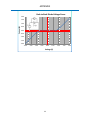
Non-Linear Junction Detector User Manual Research Electronics International, LLC 455 Security Drive, Algood, TN 38506 U.S.A. (800) 824-3190 (US Only) • +1 931-537-6032 www.reiusa.net © Copyright Research Electronics International LLC 2 Non-Linear Junction Detector This document is intended to provide guidance and instruction on using the ORION 2.4 Non-Linear Junction Detector for finding hidden electronic devices. This manual contains proprietary information intended solely for use with the ORION 2.4 Non-Linear Junction Detector. The overall effectiveness of this product, and of any surveillance countermeasure, is dependent on the threat level and the user’s ability to properly utilize the appropriate equipment. The REI Training Center offers training on technical surveillance countermeasure equipment. 3 Revision 1.10 © COPYRIGHT RESEARCH ELECTRONICS INTERNATIONAL REI products are designed and intended for legal commercial applications, however because laws and regulations vary from state to state and country to country, it is the sole responsibility of the purchaser and user/operator to check and comply with all applicable laws and regulations for the possession and operation of this equipment before and after making a purchase. WARNING: It is the responsibility of the user to comply with the appropriate radio communication laws of the country in which the ORION 2.4 is being used. This device complies with part 15 of the FCC Rules. Operation is subject to the following two conditions: (1) This device may not cause harmful interference, and (2) this device must accept any interference received, including interference that may cause undesired operation. This device complies with Industry Canada license-exempt RSS standard(s). Operation is subject to the following two conditions: (1) this device may not cause interference, and (2) this device must accept any interference, including interference that may cause undesired operation of the device. Cet appareil est conforme avec Industrie Canada RSS standard exempts de licence (s). Son utilisation est soumise aux deux conditions suivantes: (1) cet appareil ne peut pas provoquer d'interférences et (2) cet appareil doit accepter Toute interférence, y compris les interférences qui peuvent causer un mauvais fonctionnement du dispositif. Information contained in this manual including product operation and specifications is subject to change without notice. Any product or brand names contained in this manual are used only for identification purposes and are trademarks or registered trademarks of their respective holders. Patents Pending OWNER’S RECORD The Serial Number of each ORION 2.4 is located on the bottom of the unit near the battery compartment door. Please record this number and refer to it whenever you contact your dealer or Research Electronics International concerning this product. Note: Removal or alteration of the serial number automatically voids all warranties of this product. SERIAL NUMBER: _________________________ Research Electronics International, LLC 455 Security Drive, Algood, TN 38506 U.S.A. (800) 824-3190 (US Only), +1 931-537-6032 www.reiusa.net 4 This device has been tested and complies with the essential requirements of the following CE directives: LVD Directive 2006/95/EC R&TTE Directive 1999/5/EC This device does, however, make use of frequency bands whose use is not harmonized throughout the European community and is therefore identified as Class 2 equipment as indicated by the Class Identifier (Alert Symbol) Label found on the bottom side of the equipment: As Class 2 equipment, additional restrictions may need to be observed depending on where this product is used in Europe. Please consult the table below for a list of required restrictions by country. The equipment should be operated within these restrictions for the given country. See Page 24 for details on how to configure the ORION 2.4 to operate within these restrictions. Country Restrictions Austria (AT) Belgium (BE) Bulgaria (BG) Cyprus (CY) Czech Republic (CZ) Denmark (DK) Estonia (EE) Finland (FI) France (FR) Germany (DE) Greece (GR) Hungary (HU) Iceland (IS) Ireland (IE) Latvia (LV) Lithuania (LT) Luxembourg (LU) Malta (MT) Netherlands (NL) Norway (NO) Portugal (PT) Romania (RO) Slovak Republic (SK) Slovenia (SI) Sweden (SE) Switzerland/Liechtenstein (CH) 100 mW Max Transmit Power No restrictions 2.446 GHz to 2.454 GHz Transmit Freq Range No restrictions No restrictions No restrictions No restrictions No restrictions 10 mW Max Transmit Power 10 mW Max Transmit Power No restrictions 10 mW Max Transmit Power No restrictions No restrictions No restrictions 10 mW Max Transmit Power No restrictions No restrictions No restrictions No restrictions 10 mW Max Transmit Power No restrictions No restrictions 10 mW Max Transmit Power No restrictions 10 mW Max Transmit Power United Kingdom (UK) Italy (IT) Poland (PL) Spain (ES) No restrictions 10 mW Max Transmit Power No restrictions No restrictions 5 “Country” setting for ORION 2.4 (see Page 24) Austria FCC/IC/CE Bulgaria FCC/IC/CE FCC/IC/CE FCC/IC/CE FCC/IC/CE FCC/IC/CE France Germany FCC/IC/CE Hungary FCC/IC/CE FCC/IC/CE FCC/IC/CE Lithuania FCC/IC/CE FCC/IC/CE FCC/IC/CE FCC/IC/CE Portugal FCC/IC/CE FCC/IC/CE Slovenia FCC/IC/CE Switzerland or Liechtenstein FCC/IC/CE Italy FCC/IC/CE FCC/IC/CE Table of Contents PRECAUTIONS ............................................................................................................................................... 9 Equipment Description ............................................................................................................................... 10 Overview ................................................................................................................................................. 10 Keypad .................................................................................................................................................... 11 SET-UP & BASIC OPERATION ....................................................................................................................... 12 Battery Usage .......................................................................................................................................... 12 Real Time Clock Battery .......................................................................................................................... 13 Procedure................................................................................................................................................ 14 Basic ORION 2.4 Functions ...................................................................................................................... 15 Power On/Off ...................................................................................................................................... 15 Operation/Menu Item: Transmit Power Level .................................................................................... 15 Auto / Manual Transmit ...................................................................................................................... 15 Volume Level ....................................................................................................................................... 15 Volume Mute ...................................................................................................................................... 16 Adjusting the Menu Items ...................................................................................................................... 17 Menu Structure ....................................................................................................................................... 18 Quick Access Buttons .............................................................................................................................. 18 Menu Items / Operations........................................................................................................................ 19 Mode: Search2&3 ............................................................................................................................... 19 Mode: Listen 2nd AM ........................................................................................................................... 19 Mode: Listen 2nd FM............................................................................................................................ 20 Mode: Listen 3rd AM............................................................................................................................ 20 Mode: Listen 3rd FM ............................................................................................................................ 20 Mode: Freq Scan ................................................................................................................................. 20 Auto/Manual Transmit Power ............................................................................................................ 21 Manual Frequency Adjust ................................................................................................................... 21 Auto Frequency Mode ........................................................................................................................ 22 Alert: Trip Level ................................................................................................................................... 22 Vibrate Setup ...................................................................................................................................... 22 6 Gain Level ............................................................................................................................................ 22 Headlamp Setup.................................................................................................................................. 23 Battery Status...................................................................................................................................... 23 Display REI Information....................................................................................................................... 23 Display System IDs .............................................................................................................................. 23 Restore User Settings .......................................................................................................................... 23 Save/Recall User Settings.................................................................................................................... 24 Display Brightness ............................................................................................................................... 24 Country Setting ................................................................................................................................... 24 Show Clock .......................................................................................................................................... 25 Set Clock .............................................................................................................................................. 25 Standby Mode Setup........................................................................................................................... 26 Auto Off Mode Setup .......................................................................................................................... 26 Keypad Backlight Setup ....................................................................................................................... 26 Specifications .............................................................................................................................................. 27 APPENDIX .................................................................................................................................................... 29 Background Theory ................................................................................................................................. 29 7 Technical Security Training REI Training Center: REI offers the world’s largest commercially available Technical Security training facility. Training courses include classroom instruction and hands-on exercises where students perform sweep exercises in “live” environments utilizing “target rich” project rooms. The progressive course curriculum is designed for the beginner or the seasoned Technical Security Technician. Regularly scheduled courses are taught monthly; visit REI’s website (www.reiusa.net) or contact REI ([email protected]) for training dates. Contact REI for more information about technical security training and/or other equipment: www.reiusa.net 8 PRECAUTIONS PRECAUTIONS ORION 2.4 CAUTION: Any changes or modifications not expressly approved by REI could void the user’s authority to operate the equipment. The ORION 2.4 is for professional use only. The ORION 2.4 is capable of emitting a radio signal between 2.404 GHz and 2.472 GHz. The ORION 2.4 meets USA FCC transmission requirements and has been CE marked, however, it is the responsibility of the user to practice good safety procedures. In doing so, you should take the following precautions: o Do not point the antenna at a person’s eyes or head. o Maintain a distance of at least 20 cm between the antenna and the body of the user or nearby persons o Do not leave the antenna in close proximity to any part of the body for more than 5 minutes. o Do not use near flammable fluids or explosives or in any area where the use of radio communications equipment is prohibited. o Do not use in close proximity to any person fitted with a heart pacemaker, heart defibrillator, or any other life support device. For your own safety do not use the ORION 2.4 if: o The ORION 2.4 cables or its plugs become frayed or otherwise damaged. o The ORION 2.4 housing is cracked or otherwise damaged. o You suspect that the unit requires servicing Only use REI approved power sources, batteries, chargers, and accessories. The supplied power supply is REI #UIB345-15. The supplied battery pack for CE units: RRC Power Solutions Lithium Ion Rechargeable Battery pack Model #RRC2040, rated 11.25V, 2950mAh, 33.2Wh. The supplied battery pack for non-CE units: Inspired Energy Lithium Ion Rechargeable Battery pack Model #NC2040HD, rated 10.8V, 2.9Ah, 31Wh. The supplied real-time clock battery is a CR2032 coin cell battery with the following specifications: 3V nominal voltage, 225mAh nominal capacity, -30C to 60C operating temp The ORION 2.4 should not be used for normal operation while charging a battery in the ORION 2.4 unit. To return to normal operation, disconnect the AC power supply. There are no serviceable parts inside. Contact your dealer or Research Electronics International, LLC for repairs. Opening the unit will void the warranty. For your own safety do not use the AC power battery charger if: o The battery charger cables or its plugs become frayed or otherwise damaged. o The battery charger housing is cracked or otherwise damaged. o The battery charger is exposed to rain, liquid or excessive moisture. Lithium-Ion Batteries CAUTION: RISK OF EXPLOSION IF BATTERY IS REPLACED BY AN INCORRECT TYPE. DISPOSE OF USED BATTERIES ACCORDING TO THE INSTRUCTIONS. For your own safety do not use any ORION 2.4 battery if: o The battery case is cracked or otherwise damaged. o The battery is excessively hot or warm for any reason. Avoid shorting the battery, immersing in water, or exposing to fire. Also, avoid excessive physical shock or vibration. Only use the specified REI battery chargers or products to charge REI batteries There are no serviceable parts inside the battery. Contact your dealer or Research Electronics International, LLC for repairs. Opening or puncturing the unit can be dangerous and may result in injury. Using the Lithium-Ion batteries in a manner not specified by this user’s guide may override the equipment’s built-in protection mechanisms. Keep out of the reach of children. Dispose of Lithium-Ion batteries in accordance with local regulations. 9 OPERATION Equipment Description Overview 2 5 3 1 7 4 6 8 1. ANTENNA – located on opposite side of head display 2. HEAD DISPLAY – LED Bargraphs for indicating Transmit Power level, 2nd & 3rd Harmonic levels and a small informational display for indicating status and displaying the menu. 3. KEYPAD – used for controlling the ORION 2.4 4. HEADPHONE JACK – for connection of headphones to monitor audio from the unit 5. USB CONNECTOR – used for connecting to a PC for software updates 6. SPEAKER – used to monitor audio from the unit 7. POWER INPUT (under battery door) – for AC adapter (only use REI supplied AC Adapter) 8. BATTERY DOOR / BATTERY DOOR LATCH – conceals battery compartment 10 OPERATION Keypad 1 3 2 5 7 6 4 8 1. POWER – Press to Power on. Press and hold while the unit is on to Power off. A quick press of the power button while the unit is on will toggle the Transmit Power Mode (Auto or Manual) 2. AUDIO – Press and hold to Mute and Unmute the speaker or headphone. A quick press will access the Mode Sub-Menu directly. 3. TRANSMIT POWER INCREASE / UP ARROW – Increases Auto Transmit Power maximum or Manual Transmit Power level depending on current Transmit Power mode (Auto or Manual). When a menu is on the screen, this button acts as an up arrow, navigating up through subitems. 4. TRANSMIT POWER DECREASE / DOWN ARROW – Decreases Auto Transmit Power maximum or Manual Transmit Power level depending on current Transmit Power mode (Auto or Manual). When a menu is on the screen, this button acts as a down arrow, navigating down through subitems. 5. VOLUME DOWN / LEFT ARROW – Decreases the volume. When a menu is on the screen, this button acts as a left arrow, navigating to the previous menu level. 6. VOLUME UP / RIGHT ARROW – Increases the volume. When a menu is on the screen, this button acts as a right arrow, navigating to the next lower menu level. 7. SET – When a menu is on the screen, this button sets the currently active menu item. Press and hold this button to turn on or off the headlight. 8. MENU – Displays the Top Menu. If the top menu is displayed, this button exits the Menu. If a sub-item of the menu is currently displayed, this button will return you to the Top Menu. 11 OPERATION SET-UP & BASIC OPERATION The ORION 2.4 has been designed for quick and easy deployment. Depending on your application, some adjustments to the default setting may need to be made. Battery Usage Lithium-Ion rechargeable batteries have been included with your unit. To insert or switch out a new battery: 1. While pressing the latch on the bottom of the grip housing unit, raise the battery door at the rear of the unit. 2. Slide the battery into the battery slot observing proper contact alignment until it latches into place. 3. Close the battery door. The ORION 2.4 has a built-in battery charger. To charge the battery in the unit: 1. While pressing the latch on the bottom of the grip housing unit, raise the battery door at the rear of the unit. 2. With the battery already inserted in the unit, connect the provided AC power supply to the jack located just above the battery slot and to an AC source. The battery will begin charging. Charging is automatic; it will stop when the battery is fully charged. The OLED display on the head indicates the battery charge status during charging. Note: The ORION 2.4 should not be used for normal operation while charging a battery in the ORION unit. To return to normal operation, disconnect the AC power supply. 12 OPERATION Real Time Clock Battery An internal CR2032 coin cell battery provides power for the real time clock function and for maintaining saved user settings. The Real Time Clock (RTC) battery should provide years of service. In the event that the clock on the ORION 2.4 stops functioning or user settings are no longer saved, the Real Time Clock battery will need to be replaced. To replace the Real Time Clock battery: 1) Open the battery door and remove the product’s Lithium Ion Battery. 2) Remove the Phillips head screw in the panel above the battery compartment. 3) Slide the battery tray that rests above the battery compartment out of the unit. Do not disconnect the cable attached to the circuit board. 4) Locate the CR2032 battery on the right side of the battery tray circuit board. 5) Remove the old CR2032 battery from the battery clip and replace with a new CR2032 battery. Observe the battery polarity marking on the holder clip when replacing the battery; the positive (+) side should be facing up, away from the circuit board. 6) Replace the battery tray and secure with the Phillips head screw. Be careful not to pinch the attached cable while positioning the battery tray. Do not force the battery tray – the tray rests along plastic ridges in the side of the battery compartment. If positioned correctly, it should slide easily into place. Note: The provided internal coin cell is a CR2032 battery with the following specifications: 3V nominal voltage, 225 mAh nominal capacity, -30C to 60C operating temperature. 13 OPERATION After taking the ORION 2.4 out of the case, follow these simple steps to begin using it: 1. Place one of the provided rechargeable batteries in the battery compartment 2. Rotate the head for easy viewing 3. If preferred, extend the telescoping pole to a convenient length Procedure When the ORION 2.4 is turned on, it scans and displays the Transmit, 2nd Harmonic, and 3rd Harmonic spectrums. If the Frequency Mode is set to automatic (see page 22), the unit will also automatically select a quiet frequency avoiding any interference. The operator may also manually select frequencies. Two test tags are included with the ORION 2.4. One is a semiconductor diode to simulate an electronic device. The second is a steel wool pack, to simulate a corrosive metal-to-metal junction. These tags can be used to verify the proper operation of the ORION 2.4. There are two basic procedures to using any Non-Linear Junction Detector: 1. Detecting a non-linear junction and 2. Discriminating between electronics and false detection The ORION 2.4 can be configured multiple ways to aid in these two processes. 14 OPERATION Basic ORION 2.4 Functions Power On/Off To Power on or off the unit: 1. With the unit off, press and release the Power button to turn the unit on. 2. With the unit on, press and hold the Power button to turn the unit off. Operation/Menu Item: Transmit Power Level The Transmit Power Level may need to be adjusted depending on several factors, including the target or detection range. To manually adjust the Transmit Power Level: 1. Repeatedly press the Up Arrow button to increase the transmit power. The TX1 Green Bar graph will increase corresponding to the increase in transmit power. The OLED Display above the bar graphs will display the numerical value of the transmit power level. 2. Repeatedly press the Down Arrow button to decrease the transmit power. The TX1 Green Bar graph will decrease corresponding to the decrease in transmit power. The OLED Display above the bar graphs will display the numerical value of the transmit power level. Note: Whenever a menu is on the screen, the Up Arrow and Down Arrow serve as navigation keys for the menu. To adjust the Transmit Power Level, confirm that no menu is displayed. To exit a menu, press the Left Arrow button or wait about 15 seconds for the menu to time out. Auto / Manual Transmit The ORION 2.4 can be operated in either auto transmit mode or manual transmit mode. In auto transmit mode, the transmit power will automatically reduce whenever the receiver becomes saturated. In Manual transmit mode, the transmit power remains at the same level unless it is manually changed. To toggle between Auto Transmit mode and Manual Transmit Mode: 1. With the unit on & with the Transmit Power adjusted so that the Transmit Power is not OFF, press and release the Power button. The OLED screen will display the current transmit mode. Volume Level In addition to bar graphs and the OLED display, which give visual cues whenever a hidden electronic target is detected, the ORION 2.4 also has several operation modes, which give different audio cues whenever targets are detected. For details on these operation modes, see the appropriate sections later in this User’s Manual. These audio cues can be received either through the provided speaker on the unit or through headphones. 15 OPERATION To adjust the audio level of the ORION 2.4: 1. Repeatedly press the Right Arrow button to increase the volume. The OLED screen will display the volume level as it increases. 2. Repeatedly press the Left Arrow button to decrease the volume. The OLED screen will display the volume level as it decreases. Note: Whenever a menu is on the screen, the Left Arrow and Right Arrow serve as navigation keys for the menu. To adjust the Volume Level, confirm that no menu is displayed. To exit a menu, press the Left Arrow button or wait about 15 seconds for the menu to time out. Volume Mute To quickly mute the volume level: 1. Press and hold the Audio button until the audio silences. 2. Press and hold the Audio button again to return the previous volume level. 16 OPERATION Adjusting the Menu Items The ORION 2.4 can be configured for multiple situations. The majority of settings changes are handled through the menu. To adjust menu items: 1. Press the MENU button. The Main Menu will appear. 2. Press the Up or Down Arrow to begin scrolling through the Base Level Menu Items: Mode, Transmit, Set Alert, Set Gain, & Settings. 3. To enter one of the Base Level Menu Items, press the Right Arrow when that Menu Item is displayed. 4. Press the Up or Down Arrow to begin scrolling through the Level 1 Sub-Items. 5. A right arrow next to the name of a menu item indicates another sub-level of menu items. To access that sub-menu, press the Right Arrow button. 6. Any menu item without a right arrow next to the name or that is displayed with a lit background is a setting. Press the SET button to activate that setting. 7. Press the Left Arrow to go back up a menu level or to exit the menu if you are already at the Base Level. 17 OPERATION Menu Structure Base Level Level 1 Level 2 Level 3 Level 4 Search2&3 nd Mode 2 AM, 2 rd AM, 3 FM Listen nd FM, 3 rd Freq Scan Transmit Tx Power Frequency Set Alert Set Gain Trip Level Vibrate High, Med, Low Headlamp About Memory Auto Manual Manual Automatic 0, 5, 10, 15, 20, 25, 30, 35, 40, 45, 50% Enabled, Disabled On, Off Battery REI Sys ID Save, Recall, Restore Bright Country Settings Adjust Pwr Level Adjusts freq Low, Medium, High FCC/IC/CE, Austria, Bulgaria, France, Germany, Hungary, Italy, Liechtenstein, Lithuania, Portugal, Slovenia, Switzerland Show Clock General Clock Set Clock Standby Pwr Save Auto Off Key Light Selects h, m, s, M, D, Y; change selected item; Completes Disabled, 1, 2, 3, 4, 5 mins Disabled, 5, 10, 15, 20, 30 mins Off, On, Momentary Quick Access Buttons POWER Button: Quick Press – To toggle between Auto Transmit mode and Manual transmit mode, quickly press the POWER button while the unit is powered on Press & Hold – To power down the unit, press & hold the POWER button while the unit is powered on AUDIO Button: Quick Press – To access the Mode Sub-Menu directly, quickly press the AUDIO button Press & Hold – To mute the volume, press & hold the AUDIO Button until the audio silences. Press & hold the AUDIO button again to return to the previous volume level 18 OPERATION SET () Button Press & Hold – To toggle the headlamp on and off, press & hold the SET button () MENU Button Press & Hold – To scan the frequency spectrum to automatically find and select a quiet channel for use, press & hold the MENU button. Menu Items / Operations Mode: Search2&3 Purpose: This is the default search mode. In Search 2&3 mode, the 2nd and 3rd harmonics of the transmitted signal are monitored. A strong 2nd harmonic response indicates the presence of a semi-conductor junction. A strong 3rd harmonic response indicates the presence of a corrosive junction. Search 2&3 mode may provide the user with a faster method of sweeping an area, while the Listen modes described below may give better discrimination of the target. Audio: When the received 2nd harmonic signal level surpasses the set trip level, a synthetic tone will be heard. As the 2nd harmonic signal level increases, the frequency of the synthetic tone will increase. If the received 3rd harmonic signal level becomes higher than the received 2nd harmonic signal level, a lower frequency tone representing the 3rd harmonic will be heard alternating (or warbling) with the 2nd harmonic tone. Access: Menu > Mode > Search2&3 > (press set button) Quick Access: Press the Audio button to quickly access the Mode Sub-menu Mode: Listen 2nd AM Purpose: Provides an alternate audible response. The Rx2 and Rx3 LED Bargraphs representing the 2nd and 3rd harmonic response will continue to operate the same as Search2&3 mode. Audio: The received 2nd harmonic signal is AM demodulated and output through the speakers or headphones Access: Menu > Mode > Listen > 2nd AM > (press set button) Quick Access: Press the Audio button to quickly access the Mode Sub-menu 19 OPERATION Mode: Listen 2nd FM Purpose: Provides an alternate audible response. The Rx2 and Rx3 LED Bargraphs representing the 2nd and 3rd harmonic response will continue to operate the same as Search2&3 mode. Audio: The received 2nd harmonic signal is FM demodulated and output through the speakers or headphones Access: Menu > Mode > Listen > 2nd FM > (press set button) Quick Access: Press the Audio button to quickly access the Mode Sub-menu Mode: Listen 3rd AM Purpose: Provides an alternate audible response. The Rx2 and Rx3 LED Bargraphs representing the 2nd and 3rd harmonic response will continue to operate the same as Search2&3 mode. Audio: The received 3rd harmonic signal is AM demodulated and output through the speakers or headphones Access: Menu > Mode > Listen > 3rd AM > (press set button) Quick Access: Press the Audio button to quickly access the Mode Sub-menu Mode: Listen 3rd FM Purpose: Provides an alternate audible response. The Rx2 and Rx3 LED Bargraphs representing the 2nd and 3rd harmonic response will continue to operate the same as Search2&3 mode. Audio: The received 3rd harmonic signal is FM demodulated and output through the speakers or headphones Access: Menu > Mode > Listen > 3rd FM > (press set button) Quick Access: Press the Audio button to quickly access the Mode Sub-menu Mode: Freq Scan Purpose: To find a quiet frequency channel for operating the ORION 2.4. This mode scans and displays the Transmit, 2nd Harmonic, & 3rd Harmonic 20 OPERATION spectrums allowing the user to manually select a quiet channel for operation. Access: Menu > Mode > Freq Scan > (press set button) Operation: When Freq Scan mode is first entered, the Transmit Frequency bandwidth is shown. Press the Up or Down arrow to change the bandwidth to the 2nd Harmonic or 3rd Harmonic bandwidth. The selected bandwidth is displayed on the left side of the screen. Press the Left or Right arrow to move the cursor to a quiet frequency. Press the set button to change the transmit frequency of the ORION 2.4 to the cursor frequency. Quick Access: Press the Audio button to quickly access the Mode Sub-menu Note: When Frequency is set to Auto, the ORION 2.4 will automatically find a clean channel when the unit is powered on. Auto/Manual Transmit Power Purpose: To adjust the transmit power level and to switch between automatic and manual transmit modes. In auto transmit mode, the transmit power will automatically reduce whenever the receiver becomes saturated. In auto transmit mode, the set transmit power level is indicated by a blinking LED in the Tx Power bargraph. In Manual transmit mode, the transmit power remains at the same level unless it is manually changed. Menu Access: Menu > Transmit > Tx Power > or to select Automatic or Manual Quick Access: Press the Up or Down Arrow ( or ) with no menu on the screen to adjust the Transmit Power Level. Quickly press the POWER button to toggle between Auto Transmit power mode and Manual Transmit power mode. Range: 0 to 100% Manual Frequency Adjust Purpose: Sets Transmitter Frequency Menu Access: Menu > Transmit > Frequency > Manual > or to adjust frequency Range: 2.4040 GHz to 2.4720 GHz, adjustable in 1 MHz steps 21 OPERATION Display: “#.#### GHz” Auto Frequency Mode Purpose: When enabled, the unit will scan the frequency spectrums of the transmitter, 2nd harmonic, and 3rd harmonic to find and select a quiet channel for use avoiding any interference to and from other devices. This occurs on power up, as well as when Auto Frequency is selected. Menu Access: Menu > Transmit > Frequency > Automatic > (press set button) Quick Access: Alert: Trip Level Purpose: Press and hold the MENU button to perform an Auto Frequency Scan. To set a trip level for the alert tones, the vibration feedback, and target indicators (“SEMICOND” or “CORROSIVE”). The trip level is indicated by blinking LEDs on the RX2 and RX3 bargraphs. Menu Access: Menu > Set Alert > Trip Level - or to adjust Trip Level The Listen Menu must be set to “Alert Tones”: Menu > Listen > Alert Tones Range: 0%, 5%, 10%, 15%, 20%, 25%, 30%, 35%, 40%, 45%, 50% Display: “Trip: ##%” Vibrate Setup Purpose: Access: Gain Level Purpose: To enable or disable vibrator/haptic feedback Menu > Set Alert > Vibrate > or to turn off or on Sets the level of digital signal processing integration that is used to process the received signals. Access: Menu > Set Gain > or to adjust Gain Level Range: Low, Medium, High Display: “Gain Level” 22 OPERATION Headlamp Setup Purpose: To enable the headlamp on the head Access: Menu > Settings > Headlamp > or to turn off or on Quick Access: Press and hold the set button () to toggle the headlamp on and off Battery Status Purpose: To display current battery status to the customer Access: Menu > Settings > About > Battery > (press set button) To exit this screen, press any key Display: Current battery status. Display REI Information Purpose: To display general information about REI & the ORION 2.4 Access: Display System IDs Purpose: Access: Menu > Settings > About > REI > (press set button) This screen will time out automatically after about 7 seconds. To exit this screen before then, press any key To display internal component information Menu > Settings > About > Sys IDs > (press set button) The about screen will time out automatically after about 7 seconds. To exit this screen before then, press any key Restore User Settings Purpose: Anytime that the ORION 2.4 is shut down, it saves any user settings that have been changed to memory. The next time the unit is powered on, it will recall these saved settings. However at any time the original factory user settings can be restored. Access: Menu > Settings > Memory > Restore > (press set button) 23 OPERATION Save/Recall User Settings Purpose: For saving the current configuration for recall at a later time. Access: Display Brightness Purpose: To Save current settings - Menu > Settings > Memory > Save > (press set button) To Recall saved settings - Menu > Settings > Memory > Recall > (press set button) To adjust the brightness of the OLED character display and LED Bar Graphs. Access: Menu > Settings > General > Bright > or to change the setting. Range: Low, Medium, High Country Setting Purpose: The ORION 2.4 is CE Marked but is identified as Class 2 equipment due to the use of frequency bands whose use is not harmonized throughout the European community. Therefore, some countries in the EU restrict the use of the ORION 2.4. The “Country” setting allows the user to configure the ORION 2.4 for operation within the restrictions imposed by these countries. The table below lists these restrictions by country and the proper setting for the ORION 2.4 when operated within these countries. Access: Menu > Settings > General > Country > or to change the country. Range: FCC/IC/CE, Austria, Bulgaria, France, Germany, Hungary, Italy, Liechtenstein, Lithuania, Portugal, Slovenia, Switzerland Country Restrictions Austria (AT) Belgium (BE) Bulgaria (BG) Cyprus (CY) Czech Republic (CZ) Denmark (DK) 100 mW Max Transmit Power No restrictions 2.446 GHz to 2.454 GHz Transmit Freq Range No restrictions No restrictions No restrictions 24 “Country” setting for ORION 2.4 Austria FCC/IC/CE Bulgaria FCC/IC/CE FCC/IC/CE FCC/IC/CE OPERATION Country Restrictions Estonia (EE) Finland (FI) France (FR) Germany (DE) Greece (GR) Hungary (HU) Iceland (IS) Ireland (IE) Latvia (LV) Lithuania (LT) Luxembourg (LU) Malta (MT) Netherlands (NL) Norway (NO) Portugal (PT) Romania (RO) Slovak Republic (SK) Slovenia (SI) Sweden (SE) Switzerland/Liechtenstein (CH) No restrictions No restrictions 10 mW Max Transmit Power 10 mW Max Transmit Power No restrictions 10 mW Max Transmit Power No restrictions No restrictions No restrictions 10 mW Max Transmit Power No restrictions No restrictions No restrictions No restrictions 10 mW Max Transmit Power No restrictions No restrictions 10 mW Max Transmit Power No restrictions 10 mW Max Transmit Power United Kingdom (UK) Italy (IT) Poland (PL) Spain (ES) No restrictions 10 mW Max Transmit Power No restrictions No restrictions Show Clock Purpose: “Country” setting for ORION 2.4 FCC/IC/CE FCC/IC/CE France Germany FCC/IC/CE Hungary FCC/IC/CE FCC/IC/CE FCC/IC/CE Lithuania FCC/IC/CE FCC/IC/CE FCC/IC/CE FCC/IC/CE Portugal FCC/IC/CE FCC/IC/CE Slovenia FCC/IC/CE Switzerland or Liechtenstein FCC/IC/CE Italy FCC/IC/CE FCC/IC/CE To display the current time and date Access: Menu > Settings > General > Clock > Show Clock > (press set button) To exit this screen before then, press any key Display: Current time and date Set Clock Purpose: Access: To set the current time and date Menu > Settings > General > Clock > Set Clock > (press set button) Press Left or Right Arrow () to select h, m, s, M, D, Y Press the Up or Down Arrow () to change the selected item Press the set button () to complete the change and exit the set clock screen 25 OPERATION Standby Mode Setup Purpose: To configure Standby Mode. This feature will automatically put the unit into a low power state after a predetermined period of inactivity. Full operation returns when unit is picked up or handled. Access: Menu > Settings > General > Power Save > Standby > Press or to adjust timeout Range: Disabled, 1 2, 3, 4, or 5 minutes Auto Off Mode Setup Purpose: To configure Auto Off Mode. This feature will automatically shut off the unit after a predetermined period of inactivity. Power Up operation (pressing the power button) is required to return to full operation. Access: Menu > Settings > General > Power Save > Auto Off > Press or to adjust timeout Range: Disabled, 5, 10, 15, 20, or 30 minutes Keypad Backlight Setup Purpose: To configure keypad backlight Access: Menu > Settings > General > Key Backlight > or to change the setting. Range: Off, On, Momentary 26 SPECIFICATIONS Specifications TRANSMITTER Frequency Bands: 2.404 GHz – 2.472 GHz center Transmit Channels: Manual or Auto selection, more than 60 available Transmit Power: 3.3 W EIRP Power Control: Manual or Auto control Detection Modulation: Digital 1.25 MHz BW RECEIVER Simultaneous 2nd & 3rd harmonic receive Digitally Correlated Frequency Bands: Transmit Band (2.404 GHz – 2.472 GHz); Second Harmonic (4.808 GHz – 4.944 GHz); Third Harmonic (7.212 GHz – 7.416 GHz) Sensitivity: -140 dBm for both harmonics DISPLAY Antenna-Mounted Display Bar Graph Display for transmit power level, 2nd harmonic level, 3rd harmonic level, data field display, for other information (operation mode, low battery, volume, DSP gain, etc.) MECHANICAL Extension Lengths: 16-51 in (40.6 - 129.5 cm) Case Dimensions: 6.25 in x 14.9 in x 18.5 in (15.9 cm x 37.8 cm x 47.0 cm) ORION 2.4 Dim: 22.4 in x 3.75 in x 3 in (57 cm x 9 cm x 7.5 cm) Overall Extended Length: 58 in (147 cm) ORION 2.4 Weight w/ Battery: 2.8 lbs (1.3 kg) Case Weight including ORION 2.4 & Accessories: 11.6 lbs (5.2 kg) MAIN BATTERY Input AC: 100 - 240 V, 50 – 60 Hz Run Time: >8 hours per battery (typical) Charge Time: 2.5 hours per battery (typical) Batteries: Lithium Ion Rechargeable Battery (2 included) The supplied battery pack for CE units: RRC Power Solutions Lithium Ion Rechargeable Battery pack Model #RRC2040, rated 11.25V, 2950mAh, 33.2Wh. The supplied battery pack for non-CE units: Inspired Energy Lithium Ion Rechargeable Battery pack Model #NC2040HD, rated 10.8V, 2.9Ah, 31Wh. THERMAL Operating Temperature: -10 to 53C Battery Charging Temperature: 5 to 37C Storage Temperature: -20 to 60C Note: extended storage at temperatures above 40C could degrade battery & OLED display performance and life. 27 SPECIFICATIONS Product specifications and descriptions subject to change without notice 28 APPENDIX APPENDIX The ORION 2.4, designed and built by the engineers at Research Electronics International, is the latest advancement in Non-Linear Junction Evaluation. The ORION 2.4 can be used to locate electronic devices whether in furniture, walls, ceiling fixtures or elsewhere. The ORION 2.4 detects semiconductor junctions, to alert in the presence of electronics. It is important to note that due to the variations in electronic circuitry, the unit will respond differently to different electronic circuits. Therefore, the manufacturer makes no guarantee about the performance of the unit when attempting to detect hidden electronic devices. Background Theory The ORION 2.4 radiates RF energy at frequency f0 and receives energy at 2f0 & 3f0. When the radiated signal at f0 encounters a non-linear junction, some of the energy is re-radiated back at f0, 2f0, 3f0, ... It is the non-linear characteristic of the junction that generates 2f0, 3f0, ... (the 2nd & 3rd harmonics respectively). By observing the presence of returned signals at 2f0, 3f0, the user can detect the presence of a non-linear junction. Now consider a basic diode; the simplest form of an electronic non-linear junction. [ ] Eq. 1 Where i is the current of the signal, Is the leakage current, q equals the electron charge, v is the voltage, K equals Boltzman’s constant, and T is the temperature in Kelvins. A plot of this equation for a typical diode looks something like the following: 29 APPENDIX Typical Diode Voltage Curve 2.00 Current (A) 1.50 1.00 0.50 0.00 -0.50 -0.50 0.00 0.50 1.00 1.50 2.00 Voltage (V) If we approximate Eq. 1 near the origin using Taylor Series, ( [ ) ( ) ] Eq. 2 For small signals across the diodes terminals, we can reduce this to the first three terms, ( [ ) ( ) ] Eq. 3 In Eq. 3, the second term is responsible for generating the 2nd harmonic and the third term is responsible for generating the 3rd harmonic. Electronic devices typically have many different non-linear junctions (diodes, transistors, etc.) linked by wires or printed circuit board traces. Therefore energy can be radiated in and out of the device through complex paths. Typically the 2nd harmonic signal is stronger than the 3rd harmonic signal. However, some circuits can re-radiate strong 3rd harmonic signals. Other situations can also produce harmonic signals. Two dissimilar metals, joined or touching, and corroded metals return harmonic signals (passive intermodulation). These we will refer to as false junctions (Sometimes called “rusty bolt effect” or “environmental diodes”.) 30 APPENDIX The junctions in electronic devices and those in false junctions are quite different. The junctions in electronic devices are well defined, but those created by false junctions are not as well defined or as clean a physical junction. Imagine two perfect cubes joined—this would be a junction found in electronic devices. False junctions are more like two irregularly shaped items touching in places, but not in a smooth, regular pattern. http://en.wikipedia.org/wiki/File:Rust_Bolt.JPG Although there are various different types of semiconductor junctions (PN, PIN, JFET, MOSFET, etc.), they all produce clean, predictable junction characteristics. For the junctions found in electronic devices, this equation produces a predictable, but unsymmetrical curve. False junctions produce a less regular curve, one that is noisy and unpredictable, yet they are typically symmetrical: their curve is mirrored for negative values. The current/voltage characteristics are illustrated below. Semiconductor Junction Characteristics False Junction Characteristics 31 APPENDIX This level of regularity in the junction results in differences in the harmonic signals. When the ORION 2.4 radiates a signal that is returned by the junction in electronics, it results in a strong 2nd harmonic signal and a weak 3rd harmonic. A false junction returns a very weak 2nd harmonic and a strong 3rd. A B ORION 2.4 COMPARISON OF HARMONIC LEVELS nd rd (A – Semiconductor, B – False Junction; Bargraphs on the right are the 2 and 3 harmonic levels) As mentioned earlier, some semiconductor circuits re-radiate a strong third harmonic signal. For example with two diodes connected back to back (see below), the shape of the voltage curve resembles the symmetry of a false junction and produces a stronger third harmonic than does a single diode. 32 APPENDIX Back to Back Diode Voltage Curve 2.00 1.50 Current (A) 1.00 0.50 0.00 -0.50 -1.00 -1.50 -2.00 -2.00 -1.50 -1.00 -0.50 0.00 0.50 Voltage (V) 33 1.00 1.50 2.00