1
GOT-A900 Series Operating Manual
(SW4D5C-GOTR-PACKE compatible
Extended•Option Functions Manual)
MITSUBISHI Graphic Operation Terminal
• SAFETY PRECAUTIONS •
(Always read these instructions before using this equipment.)
Before using this product, please read this manual and the relevant manuals introduced in this manual carefully
and pay full attention to safety to handle the product correctly.
The instructions given in this manual are concerned with this product. For the safety instructions of the
programmable controller system, please read the CPU module user's manual.
In this manual, the safety instructions are ranked as "DANGER" and "CAUTION".
!
DANGER
! CAUTION
Indicates that incorrect handling may cause hazardous conditions,
resulting in death or severe injury.
Indicates that incorrect handling may cause hazardous conditions,
resulting in medium or slight personal injury or physical damage.
Note that the ! CAUTION level may lead to a serious consequence according to the circumstances.
Always follow the instructions of both levels because they are important to personal safety.
Please save this manual to make it accessible when required and always forward it to the end user.
[PRECAUTION WHEN PERFORMING THE TEST OPERATION]
! CAUTION
• Read the manual carefully and fully understand the operation before the test operation (ON/OFF of
bit devices, modifying current value of a word device, modifying timer/counter setting, modifying the
current value, or modifying the current value of a buffer memory) of system monitor, special function
module monitor, and ladder monitor.
In addition, never modify data in a test operation to a device which performs a crucial operation to the
system.
It may cause an accident by a false output or malfunction.
A-1
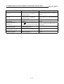
Revisions
*The manual number is given on the bottom left of the back cover.
Print Date
Jan.,2000
May.,2000
*Manual Number
SH(NA)-080069-A
SH(NA)-080069-B
Revision
First edition
Partial additions
Section 1.2, 4.1, 4.5
This manual confers no industrial property rights or any rights of any other kind, nor does it confer any patent
licenses. Mitsubishi Electric Corporation cannot be held responsible for any problems involving industrial property
rights which may occur as a result of using the contents noted in this manual.
2000 MITSUBISHI ELECTRIC CORPORATION
A-2
INTRODUCTION
Thank you for choosing the Mitsubishi Graphic Operation Terminal.
Before using the equipment, please read this manual carefully to use the equipment to
its optimum.
Please forward a copy of this manual to the end user.
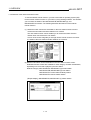
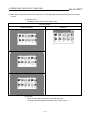
Whereabouts and Usage of This Manual
The manuals relating to SW4D5C-GOTR-PACKE are available in the following types.
The manuals are classified according to their purposes. Please read the proper
manuals to understand the handling, operation and functions of the GOT unit and
SW4D5C-GOTR-PACKE.
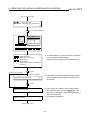
[ A985GOT Graphic Operation Terminal User’s Manual(Hardware) ]
• To know the features of A985GOT unit.
• To confirm the specifications of A985GOT unit.
• To know the part names of A985GOT unit.
• To know how to install and wire A985GOT unit.
• To know the outline dimension drawing of A985GOT unit.
A985GOT
Graphic Operation
Terminal
User's Manual
(Hardware)
Found in the packing
of the A985GOT unit.
[ A975GOT-TBA/TBD(-B), A970GOT-TBA/TBD(-B), A970GOT-SBA/SBD, A970GOT-LBA/LBD, A960GOTEBA/EBD User’s Manual(Hardware) ]
• To know the features of A975GOT/A970GOT/A960GOT unit.
A975GOT-TBA/TBD(-B)
A970GOT-TBA/TBD(-B)
• To confirm the specifications of A975GOT/A970GOT/A960GOT unit. A970GOT-SBA/SBD
A970GOT-LBA/LBD
• To know the part names of A975GOT/A970GOT/A960GOT unit.
A960GOT-EBA/EBD
user's Manual
• To know how to install and wire A975GOT/A970GOT/A960GOT
(Hardware)
unit.
• To know the outline dimension drawing of
A975GOT/A970GOT/A960GOT unit.
Found in the packing
of the A975GOT/
A970GOT/A960GOT
unit.
[ A985GOT-TBA-EU, A975GOT-TBA-EU, A970GOT-TBA-EU, A970GOT-SBA-EU, A960GOT-EBA-EU
User’s Manual(Hardware) ]
• To know the features of the GOT-A900 series EMC directive Low
voltage directive compliant unit.
• To confirm the specifications of the GOT-A900 series EMC directive
Low voltage directive compliant unit.
• To know the part names of the GOT-A900 series EMC directive Low
voltage directive compliant unit.
• To know how to install and wire the GOT-A900 series EMC directive
Low voltage directive compliant unit.
• To know the outline dimension drawing of the GOT-A900 series
EMC directive Low voltage directive compliant unit.
A-3
A985GOT-TBA-EU
A975GOT-TBA-EU
A970GOT-TBA-EU
A970GOT-SBA-EU
A960GOT-EBA-EU
User's Manual
(Hardware)
Found in the packing
of the
A985GOT-TBA-EU,
A975GOT-TBA-EU,
A970GOT-TBA-EU,
A970GOT-SBA-EU,
A960GOT-EBA-EU
unit.
[ A950GOT-TBD/SBD/LBD (-M3), A951GOT-QTBD/QSBD/QLBD (-M3), A951GOT-TBD/SBD/LBD (-M3),
A953GOT-TBD/SBD/LBD (-M3), A956GOT-TBD/SBD/LBD (-M3) User's Manual(Hardware) ]
• To know the features of A950GOT/A951GOT/A953GOT/A956GOT unit.
• To confirm the specifications of
A950GOT/A951GOT/A953GOT/A956GOT unit.
• To know the part names of
A950GOT/A951GOT/A953GOT/A956GOT unit.
• To know how to install and wire
A950GOT/A951GOT/A953GOT/A956GOT unit.
• To know the outline dimension drawing of
A950GOT/A951GOT/A953GOT/A956GOT unit.
A950GOT-TBD/SBD/LBD(-M3)
A951GOT-QTBD/QSBD/QLBD(-M3)
A951GOT-TBD/SBD/LBD(-M3)
A953GOT-TBD/SBD/LBD(-M3)
A956GOT-TBD/SBD/LBD(-M3)
User's Manual
(Hardware)
Found in the packing
of the A950GOT/
A951GOT/A953GOT/
A956GOT unit.
[ GOT-A900 Series Option Unit User's Manuals ]
• To know the features of the corresponding GOT-A900 series option unit.
• To confirm the specifications of the corresponding GOT-A900 series option unit.
• To know the part names of the corresponding GOT-A900 series option unit.
• To know the outline dimension drawing of the corresponding GOT-A900 series
option unit.
GOT-A900 Series
Option Unit
User's Manuals
Found in the packing
of the corresponding
GOT-A900 series
option unit.
[ A985GOT/ A975GOT/ A970GOT/ A960GOT User’s Manual ]
• To know the features of A985GOT/ A975GOT/ A970GOT/ A960GOT unit.
• To confirm the component devices of A985GOT/ A975GOT/ A970GOT/
A960GOT unit.
• To confirm the specifications of A985GOT/ A975GOT/ A970GOT/ A960GOT unit.
• To know the part names of A985GOT/ A975GOT/ A970GOT/ A960GOT unit.
• To fit various units to A985GOT/ A975GOT/ A970GOT/ A960GOT unit.
• To know how to install and wire A985GOT/ A975GOT/ A970GOT/ A960GOT unit.
• To know how to maintain and inspect A985GOT/ A975GOT/ A970GOT/
A960GOT unit.
• To confirm the error codes of A985GOT/ A975GOT/ A970GOT/ A960GOT unit.
• To know the outline dimension drawing of A985GOT/ A975GOT/ A970GOT/
A960GOT unit.
A985GOT/A975GOT
/A970GOT/A960GOT
User's Manual
Available as an option.
[ A950GOT/ A951GOT/ A953GOT/ A956GOT User’s Manual ]
• To know the features of A950GOT/ A951GOT/ 953GOT/ A956GOT unit.
• To confirm the component devices of A950GOT/ A951GOT/ 953GOT/
A956GOT unit.
• To confirm the specifications of A950GOT/ A951GOT/ 953GOT/ A956GOT unit.
• To know the part names of A950GOT/ A951GOT/ 953GOT/ A956GOT unit.
• To fit various units to A950GOT/ A951GOT/ 953GOT/ A956GOT unit.
• To know how to install and wire A950GOT/ A951GOT/ 953GOT/ A956GOT unit.
• To know how to maintain and inspect A950GOT/ A951GOT/ 953GOT/
A956GOT unit.
• To confirm the error codes of A950GOT/ A951GOT/ 953GOT/ A956GOT unit.
• To know the outline dimension drawing of A950GOT/ A951GOT/ 953GOT/
A956GOT unit.
A-4
A950GOT/A951GOT
/A953GOT/A956GOT
User's Manual
Available as an option.
[ GOT-A900 Series User’s Manual(SW4D5C-GOTR-PACKE compatible Connection System Manual) ]
• To know the connection forms available for the GOT-A900 series.
• To confirm the specifications of each connection form.
• To know the system configuration of each connection form.
• To know how to set the unit used.
• To confirm the connection diagrams of the connection cables.
SW4D5C-GOTR-PACKE
Contained in the
SW4D5C-GOTR-PACKE
as PDF data.
* The printed matter is also available
as an option.
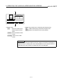
[ SW4D5C-GOTR-PACKE(V) Operating Manual ]
• To install the software into the personal computer.
• To start each software.
• To know how to connect the personal computer and GOT.
• To know the screen makeup of the software.
• To grasp the outline of various monitoring functions.
• To know the procedure of displaying the monitor screen.
• To know how to use the help function.
SW4D5C-GOTR-PACKE(v)
Operating Manual
Found in the packing
of SW4D5C-GOTR-PACKE.
* Contained also in the SW4D5C-GOTRPACKE as PDF data.
[ SW4D5C-GOTR-PACKE Help Functions]
• To confirm how to operate each software of SW4D5C-GOTRPACKE.
• To confirm how to set various object functions.
SW4D5C-GOTR-PACKE
Incorporated in
each software of
SW4D5C-GOTR-PACKE
[ GOT-A900 Series Operating Manual (SW4D5C-GOTR-PACKE compatible Extended • Option Functions Manual ) ]
• To perform the utility function.
• To perform the system monitoring function.
• To perform the ladder monitoring function.
• To perform the special function unit monitoring function.
• To perform the network monitoring function.
• To perform the list editor function.
SW4D5C-GOTR-PACKE
Contained in the
SW4D5C-GOTR-PACKE
as PDF data.
* The printed matter is also available
as an option.
[ GOT Operations Guide ]
• To learn the sequence of operations by creating a simple screen
using the drawing software (the screen displays of the drawing
software introduced in the GOT Operations Guide are partly different
from those of SW4D5C-GOTR-PACKE).
A-5
GOT Operations Guide
Contained in the
GOT Operations Guide.
Abbreviations, generic terms and special terms used in this manual
Abbreviations, generic terms and special terms used in this manual are described as
follows:
Abbreviations, generic terms and
special terms
A985GOT
A975GOT
A970GOT
A97*GOT
A960GOT
A956GOT
A953GOT
A951GOT
A951GOT-Q
A950GOT
A950 handy GOT
A95*GOT
GOT
Memory
OS
A9GT-QBUSS
A9GT-QBUS2S
A9GT-BUSS
A9GT-BUS2S
Bus connection board
A9GT-RS4
A9GT-RS2
A9GT-RS2T
Serial communication board
Communication board
A9GT-QBUS2SU
A9GT-BUSSU
A9GT-BUS2SU
A7GT-BUSS
A7GT-BUS2S
Bus connection unit
A7GT-J71AP23
A7GT-J71AR23
A7GT-J71AT23B
Data link unit
A7GT-J71LP23
A7GT-J71BR13
Network unit
A8GT-J61BT13
A8GT-J61BT15
CC-Link communication unit
Communication unit
Protection sheet
Backlight
Debug stand
PC card ( memory card )
Memory board
Description
Generic term of A985GOT-TBA, A985GOT-TBD and A985GOT-TBA-EU
Generic term of A975GOT-TBA-B, A975GOT-TBD-B, A975GOT-TBA, A975GOT-TBD and
A975GOT-TBA-EU
Generic term of A970GOT-TBA-B A970GOT-TBD-B, A970GOT-TBA, A970GOT-TBD, A970GOTSBA, A970GOT-SBD, A970GOT-LBA, A970GOT-LBD, A970GOT-TBA-EU and A970GOT-SBA-EU
Generic term of A975GOT and A970GOT
Generic term of A960GOT-EBA, A960GOT-EBD and A960GOT-EBA-EU
Generic term of A956GOT-TBD, A956GOT-SBD, A956GOT-LBD, A956GOT-TBD-M3, A956GOTSBD-M3 and A956GOT-LBD-M3
Generic term of A953GOT-TBD, A953GOT-SBD, A953GOT-LBD, A953GOT-TBD-M3, A953GOTSBD-M3 and A953GOT-LBD-M3
Generic term of A951GOT-TBD, A951GOT-SBD, A951GOT-LBD, A951GOT-TBD-M3, A951GOTSBD-M3 and A951GOT-LBD-M3
Generic term of A951GOT-QTBD, A951GOT-QSBD, A951GOT-QLBD, A951GOT-QTBD-M3, A951GOTQSBD-M3 and A951GOT-QLBD-M3
Generic term of A950GOT-TBD, A950GOT-SBD, A950GOT-LBD, A950GOT-TBD-M3, A950GOTSBD-M3 and A950GOT-LBD-M3
Generic term of A953GOT-SBD-M3-H and A953GOT-LBD-M3-H
Generic term of A956GOT, A953GOT, A951GOT, A951GOT-Q, A950GOT and A950 handy GOT
Generic term of A985GOT, A97*GOT, A960GOT and A95*GOT
Abbreviation of memory (flash memory) in the GOT
Abbreviation of GOT system software
Abbreviation of A9GT-QBUSS type bus connection board
Abbreviation of A9GT-QBUS2S type multi-drop bus connection board
Abbreviation of A9GT-BUSS type bus connection board
Abbreviation of A9GT-BUS2S type multi-drop bus connection board
Generic term of A9GT-QBUSS, A9GT-QBUS2S, A9GT-BUSS and A9GT-BUS2S
Abbreviation of A9GT-RS4 type serial communication board
Abbreviation of A9GT-RS2 type serial communication board
Abbreviation of A9GT-RS2T type serial communication board
Generic term of A9GT-RS4, A9GT-RS2 and A9GT-RS2T
Generic term of bus connection board and serial communication board
Abbreviation of A9GT-QBUS2SU type multi-drop bus connection unit
Abbreviation of A9GT-BUSSU type bus connection unit
Abbreviation of A9GT-BUS2SU type multi-drop bus connection unit
Abbreviation of A7GT-BUSS type bus connection unit
Abbreviation of A7GT-BUS2S multi-drop bus connection unit
Generic term of A9GT-QBUS2SU, A9GT-BUS2SU, A9GT-BUS2SU, A7GT-BUSS and A7GT-BUS2S
Abbreviation of A7GT-J71AP23 type data link unit
Abbreviation of A7GT-J71AR23 type data link unit
Abbreviation of A7GT-J71AT23B type data link unit
Generic term of A7GT-J71AP23, A7GT-J71AR23 and A7GT-J71AT23B
Abbreviation of A7GT-J71LP23 type network unit
Abbreviation of A7GT-J71BR13 type network unit
Generic term of A7GT-J71LP23 and A7GT-J71BR13
Abbreviation of A8GT-J61B13 CC-Link communication unit
Abbreviation of A8GT-J61B15 CC-Link communication unit
Generic term of A8GT-J61BT13 and A8GT-J61BT15
Generic term of bus connection unit, data link unit, network unit and CC-Link communication unit
Abbreviation of A9GT-80PSC, A9GT-70PSC, A9GT-60PSC and A9GT-50PSC type transparent
protection sheets
Abbreviation of A9GT-80LTT, A9GT-70LTTB, A9GT-70LTT, A9GT-70LTS and
A9GT-50LT type backlights
Abbreviation of A9GT-80STAND, A9GT-70STAND and A9GT-50STAND type debug stand
Abbreviation of PC card with PCMCIA Ver.2.1
Abbreviation of A9GT-FNB, A9GT-FNB1M, A9GT-FNB2M, A9GT-FNB4M, A9GT-FNB8M, A9GTQFNB, A9GT-QFNB4M, A9GT-QFNB8M type option function memory board
A-6
Abbreviations, generic terms and
special terms
External I/O unit
Printer interface unit
Memory card interface unit
Attachment
QCPU (Q Mode)
QCPU (A Mode)
QCPU
QnACPU (Large Type)
QnACPU (Small Type)
QnACPU
AnUCPU
AnACPU
AnNCPU
ACPU (Large Type)
A2US(H)CPU
AnS(H)CPU
A1SJ(H)CPU
ACPU (Small Type)
ACPU
FX0 series
FX0N series
FX0S series
FX1 series
FX1S series
FX2 series
FX2C series
FX2N series
FX2NC series
Description
Drawing software
Data conversion software
Debug software
Object
Windows95
Abbreviation of A9GT-70KBF and A8GT-50KBF type external I/O interface unit
Abbreviation of A9GT-50PRF type printer interface unit
Abbreviation of A1SD59J-MIF memory card interface unit
Generic term of A77GT-96ATT/A85GT-95ATT/A87GT-96ATT/A87GT-97ATT attachments
Generic term of Q02CPU, Q02HCPU, Q06HCPU, Q12HCPU and Q25HCPU CPU units
Generic term of Q02CPU-A, Q02HCPU-A and Q06HCPU-A CPU units
Generic term of QCPU (Q Mode) and QCPU (A Mode)
Generic term of Q2ACPU, Q2ACPU-S1, Q3ACPU, Q4ACPU and Q4ARCPU CPU units
Generic term of Q2ASCPU, Q2ASCPU-S1, Q2ASHCPU and Q2ASHCPU-S1 CPU units
Generic term of QnACPU (Large Type) and QnACPU (Small Type)
Generic term of A2UCPU, A2UCPU-S1, A3UCPU and A4UCPU CPU units
Generic term of A2ACPU, A2ACPU-S1 and A3ACPU CPU units
Generic term of A1NCPU, A2NCPU, A2NCPU-S1 and A3NCPU CPU units
Generic term of AnUCPU, AnACPU and AnNCPU CPU units
Generic term of A2USCPU, A2USCPU-S1 and A2USHCPU-S1 CPU units
Generic term of A1SCPU, A1SHCPU, A2SCPU and A2SHCPU CPU units
Generic term of A1SJCPU-S3 and A1SJHCPU CPU units
Generic term of A2US(H)CPU, AnS(H)CPU and A1SJ(H)CPU CPU units
Generic term of ACPU (Large Type), ACPU (Small Type) and A1FXCPU CPU units
Generic term of FX0 series CPU unit
Generic term of FX0N series CPU unit
Generic term of FX0S series CPU unit
Generic term of FX1 series CPU unit
Generic term of FX1S series CPU unit
Generic term of FX2 series CPU unit
Generic term of FX2C series CPU unit
Generic term of FX2N series CPU unit
Generic term of FX2NC series CPU unit
Generic term of FX0 series, FX0N series, FX0S series, FX1 series, FX1S series, FX2 series , FX2C
series, FX2N series, FX2NC series CPU unit
Generic term of A373UCPU, A373UCPU-S3, A273UCPU, A273UHCPU, A273UHCPU-S3,
A171SCPU-S3, A171SHCPU, A172SHCPU CPU unit
Generic term of LM610, LM7600, LM8000 CPU unit
Generic term of C200HS, C200H, C200HX, C200HG, C200HE, CQM1, C1000H,C2000H,CV1000
CPU unit
Generic term of GL60S, GL60H, GL70H, GL120, GL130, CP-9200SH, CP-9300MS, MP-920, MP-930,
CP-9200(H) and PROGIC-8 CPU unit
Generic term of SLC 5/03, SLC 5/04 CPU unit
Generic term of JW-21CU, JW-22CU, JW-31CUH, JW-32CUH, JW-33CUH, JW-50CUH,
JW-70CUH, JW-100CUH CPU unit
Generic term of T3, T3H CPU unit
Generic term of SIMATIC S7-300 Series and SIMATIC S7-400 Series CPU unit
Generic term of Omron PLC, Yasukawa PLC , Allen-Bradley PLC , Sharp PLC , Toshiba PLC and
SIEMENS PLC CPU unit
Generic term of SW4D5C-GOTR-PACKE software package and SW4D5C-GOTR-PACKEV
software package
Abbreviation of image creation software GOT Screen Designer for GOT900
Abbreviation of data conversion software GOT Converter for GOT900
Abbreviation of debugging software GOT Debugger
Setting data for dynamic image
1
Abbreviation of Microsoft Windows95∗
Windows98
Abbreviation of Microsoft Windows98∗
Windows NT4.0
Windows
Acrobat Reader
Personal Computer
Abbreviation of Microsoft Windows NT Workstation 4.0∗
Generic term of Windows95, Windows98 and Windows NT4.0
2
Abbreviation of Adobe Acrobat Reader3.0 ∗
Windows compatible Personal Computer that can install SW4D5C-GOTR-PACKE
FXCPU
Motion controller CPU
FA controller
Omron PLC
Yasukawa PLC
Allen-Bradley PLC
Sharp PLC
Toshiba PLC
SIEMENS PLC
Other PLC
SW4D5C-GOTR-PACKE
1
1
*1 Microsoft Windows95, Microsoft Windows98 and Microsoft Windows NT Workstation 4.0 are the trademarks of Microsoft Corporation, U.S.
*2 Adobe and Adobe Acrobat are the trademarks of Adobe Systems Incorporated. (C)1998 Adobe Systems Incorporated. All right reserved.
A-7
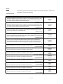
Manual
The following manuals related to this product are available. Obtain the manuals as
required the according to this table.
• Related manual
Manual name
Manual number (Model code)
A985GOT/A975GOT/A970GOT/A960GOT User’s Manual
Explains the specifications, general system configuration, component devices, part names, option
unit loading methods, installation and wiring methods, maintenance and inspection methods, and
error codes of A985GOT/A975GOT/A970GOT/A960GOT unit.
(Available as option)
A950GOT/A951GOT/A953GOT/A956GOT User’s Manual
Explains the specifications, general system configuration, component devices, part names, option
unit loading methods, installation and wiring methods, maintenance and inspection methods, and
error codes of A950GOT/A951GOT/A953GOT/A956GOT unit.
(Available as option)
GOT-A900 Series User’s Manual (SW4D5C-GOTR-PACKE compatible Connection System Manual)
Gives the specifications, system configuration, setting method and connection diagram of each
connection form available for the GOT-A900 series.
(Available as option)
GOT-A900 Series Operating Manual (SW4D5C-GOTR-PACKE compatible Extended • Option Functions Manual)
Provides the specifications of the utility, system monitoring, ladder monitoring, special function unit
monitoring, network monitoring functions and list editor functions available for the GOT-A900 series
and how to operate the dedicated monitor screen.
(Available as option)
SW4D5C-GOTR-PACKE(V) Operating Manual
Deals with how to install and start the SW4D5C-GOTR-PACKE, its system configuration, the
screen makeup of the software package, the general description of various monitoring functions,
the procedure for displaying the monitor screen on the GOT, and how to use the help function.
(Found in the packing of the SW4D5C-GOTR-PACKE)
A9GT-QBUSS Type Bus Connection Board User's Manual
Describes specifications, part names and installation of A9GT-QBUSS.
(with A9GT-QBUSS)
A9GT-QBUS2S Type Multi-Drop Bus Connection Board User's Manual
Describes specifications, part names and installation of A9GT-QBUS2S.
(with A9GT-QBUS2S)
A9GT-QBUS2SU Type Multi-Drop Bus connection unit User's Manual
Describes specifications, part names and installation of A9GT- QBUS2SU.
(with A9GT- QBUS2SU)
A9GT-BUSSU Type Bus connection unit User's Manual
Describes specifications, part names and installation of A9GT-BUSSU.
(with A9GT-BUSSU)
A9GT-BUS2SU Type Multi-Drop Bus connection unit User's Manual
Describes specifications, part names and installation of A9GT-BUS2SU.
(with A9GT-BUS2SU)
A9GT-BUSS Type Bus Connection Board User's Manual
Describes specifications, part names and installation of A9GT-BUSS.
(with A9GT-BUSS)
A9GT-BUS2S Type Multi-Drop Bus Connection Board User's Manual
Describes specifications, part names and installation of A9GT-BUS2S.
(with A9GT-BUS2S)
A7GT-BUSS Type bus connection unit User's Manual
Describes specifications, part names and operation of A7GT-BUSS.
(with A7GT-BUSS)
A-8
SH-4005
(13JL70)
SH-080018
(13JL92)
SH-080070
(13JR11)
SH-080069
(13J979)
IB-0800094
(13J978)
IB-0800073
(13JQ75)
IB-0800074
(13JQ76)
IB-0800083
(13JQ83)
IB-0800076
(13JQ78)
IB-0800077
(13JQ79)
IB-68953
(13JM87)
IB-68954
(13JM88)
IB-66760
(13JL07)
Manual name
Manual number (Model code)
A7GT-BUS2S Type multi-drop bus connection unit User's Manual
Describes specifications, part names and operation of A7GT-BUS2S.
(with A7GT-BUS2S)
A9GT-RS4 Type Serial Communication Board User's Manual
Describes specifications, part names and installation of A9GT-RS4.
(with A9GT-RS4)
A9GT-RS2 Type Serial Communication Board User's Manual
Describes specifications, part names and installation of A9GT-RS2.
(with A9GT-RS2)
A9GT-RS2T Type Serial Communication Board User's Manual
Describes specifications, part names and installation of A9GT-RS2T.
(with A9GT-RS2T)
A7GT-J71AP23/R23 Type Data Link Unit User's Manual
Describes specifications, part names and installation of A7GT-J71AP23/R23.
(with A7GT-J71AP23/R23)
A7GT-J71AT23B Type Data Link Unit User's Manual
Describes specifications, part names and installation of A7GT-J71AT23B.
(with A7GT-J71AT23B)
A7GT-J71LP23/BR13 Type Network Unit User's Manual
Describes specifications, part names and installation of A7GT-J71LP23/BR13.
(with A7GT-J71LP23/BR13)
A8GT-J61BT13 Type CC-Link Communication Unit User's Manual
Describes specifications, part names and installation of A8GT-J61BT13.
(with A8GT-J61BT13)
A8GT-J61BT15 Type CC-Link Communication Unit User's Manual
Describes specifications, part names and installation of A8GT-J61BT15.
(with A8GT-J61BT15)
A9GT-80LTT Type Back light Unit User's Manual
Describes specifications, part names and installation of A9GT-80LTT.
(with A9GT-80LTT)
A9GT-70LTT Type Back light Unit User's Manual
Describes specifications, part names and installation of A9GT-70LTT.
(with A9GT-70LTT)
A9GT-70LTS Type Back light Unit User's Manual
Describes specifications, part names and installation of A9GT-70LTS.
(with A9GT-70LTS)
A9GT-70LTTB Type Back light Unit User's Manual
Describes specifications, part names and installation of A9GT-70LTTB.
(with A9GT-70LTTB)
A9GT-50LT type backlight User's Manual
Describes specifications and operation of A9GT-50LT.
(with A9GT-50LT)
A9GT-80STAND User's Manual
Describes specifications, part names and installation of A9GT-80STAND.
(with A9GT-80STAND)
A9GT-70STAND User's Manual
Describes specifications, part names and installation of A9GT-70STAND.
(with A9GT-70STAND)
A9GT-50STAND User's Manual
Describes specifications and operation of A9GT-50STAND.
(with A9GT-50STAND)
A-9
IB-66761
(13JL08)
IB-68955
(13JM89)
IB-68956
(13JM90)
IB-0800022
(13JQ38)
IB-66438
(13JE26)
IB-66439
(13JA81)
IB-66558
(13JE94)
IB-66838
(13JL56)
IB-66788
(13JL29)
IB-80027
(13JQ21)
IB-68982
(13JM97)
IB-68984
(13JM99)
IB-80033
(13JQ25)
IB-0800020
(13JQ29)
IB-80028
(13JQ22)
IB-68981
(13JM96)
IB-0800021
(13JQ30)
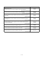
Manual name
Manual number (Model code)
Add-on memory board for A9GT-FNB, A9GT-FNB1M, A9GT-FNB2M, A9GT-FNB4M and A9GTFNB8M type option function
Describes specifications, part names and installation of A9GT-FNB (1M/2M/4M/8M).
(with A9GT-FNB (1M/2M/4M/8M))
IB-68975
(13JM91)
Add-on memory board for A9GT-QFNB, A9GT-QFNB4M and A9GT-QFNB8M type option function
Describes specifications, part names and installation of A9GT-QFNB (4M/8M).
(with A9GT- QFNB (4M/8M))
IB-0800051
(13JQ62)
A9GT-70KBF Type External I/O Interface Unit User's Manual
Describes specifications, system configurations, part names and installation/wiring methods of
A9GT-70KBF.
(with A9GT-70KBF)
IB-80018
(13JQ14)
A8GT-50KBF Type External I/O Interface Unit User's Manual
Describes specifications, system configurations, part names and installation/wiring methods of
A8GT-50KBF.
(with A8GT-50KBF)
IB-66787
(13JL28)
A9GT-50PRF type printer interface unit user's manual
Describes specifications, system configuration, part names, installation method and external
dimensions of A9GT-50PRF.
(with A9GT-50PRF)
IB-0800019
(13JQ28)
A8GT-TK Type Numerical Keypad Panel User's Manual
Describes specifications, part names and installation of A8GT-TK.
(with A8GT-TK)
A9GT-QCNB Type bus connector conversion box User's Manual
Describes specifications, part names and installation of A9GT-QCNB.
(with A9GT-QCNB)
A7GT-CNB Type bus connector conversion box User's Manual
Describes specifications, part names and installation of A7GT-CNB.
IB-0800082
(13JQ82)
BCN-P5138
(with A7GT-CNB)
A - 10
IB-66832
(13JL51)
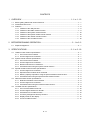
CONTENTS
1
OVERVIEW .................................................................................................... 1 - 1 to 1 - 16
1.1
1.2
1.3
2
BEFORE BEGINNING OPERATION................................................................ 2 - 1 to 2- 2
2.1
3
Before getting started with various functions ..................................................................................... 1 - 1
Precautions before use....................................................................................................................... 1 - 1
Features .............................................................................................................................................. 1 - 6
1.3.1 Features of the utility function................................................................................................. 1 - 6
1.3.2 Features of the ladder monitor function.................................................................................. 1 - 8
1.3.3 Features of the system monitor function .............................................................................. 1 - 10
1.3.4 Features of the special module monitor function ................................................................. 1 - 12
1.3.5 Features of the network monitor function............................................................................. 1 - 14
1.3.6 Features of the List editor function ....................................................................................... 1 - 16
Required equipment ........................................................................................................................... 2 - 1
SPECIFICATIONS ......................................................................................... 3 - 1 to 3 - 18
3.1
3.2
3.3
3.4
3.5
Ladder monitor function specifications............................................................................................... 3 - 1
3.1.1 PLC CPUs to be monitored .................................................................................................... 3 - 1
3.1.2 Access ranges to be monitored .............................................................................................. 3 - 1
System monitor function specifications .............................................................................................. 3 - 2
3.2.1 PLC CPUs to be monitored .................................................................................................... 3 - 2
3.2.2 Access ranges to be monitored .............................................................................................. 3 - 2
3.2.3 Names of devices to be monitored......................................................................................... 3 - 2
3.2.4 Precautions when using the system monitor function ........................................................... 3 - 2
Special module monitor function specifications ................................................................................. 3 - 4
3.3.1 Access ranges to be monitored .............................................................................................. 3 - 4
3.3.2 Special function modules to be monitored ............................................................................. 3 - 4
3.3.3 Memory capacity required for using the special module monitor function ............................ 3 - 5
3.3.4 Precautions when using the special module monitor function .............................................. 3 - 6
Network monitor function specifications............................................................................................. 3 - 8
3.4.1 Network information to be monitored ..................................................................................... 3 - 8
3.4.2 Access ranges to be monitored .............................................................................................. 3 - 9
3.4.3 Precautions when using the network monitor function .......................................................... 3 - 9
List editor function specifications...................................................................................................... 3 - 10
3.5.1 PLC CPU that allows for list edit........................................................................................... 3 - 10
3.5.2 Access range that allows for list edit .................................................................................... 3 - 10
3.5.3 Precautions for List editor function ....................................................................................... 3 - 10
3.5.4 List of key arrangement and key functions........................................................................... 3 - 11
3.5.5 Display format on the display................................................................................................ 3 - 14
3.5.6 List of List editor function ...................................................................................................... 3 - 17
A - 11
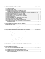
4
OPERATING THE UTILITY FUNCTION........................................................ 4 - 1 to 4 - 18
4.1
4.2
4.3
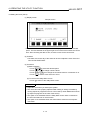
Utility function table............................................................................................................................. 4 - 1
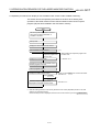
Selecting the utility function ................................................................................................................ 4 - 2
Selecting the required function on the utility menu screen
(Adjusting the brightness/contrast of the monitor screen) ................................................................. 4 - 3
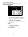
4.4 Copying the monitor data/OS data between the internal memory and memory card (Screen & OS copy) .. 4 - 5
4.5 Setting the operating environment of the GOT (Setup)..................................................................... 4 - 7
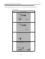
4.6 Running diagnostic checks on GOT hardware (self-test)................................................................ 4 - 11
4.7 Displaying GOT memory information (memory information)........................................................... 4 - 12
4.8 Setting the Clock (Clock) .................................................................................................................. 4 - 13
4.9 Displaying the display area cleanup screen (screen cleanup)........................................................ 4 - 14
4.10 Changing security levels (security password).................................................................................. 4 - 15
4.11 Controlling limited access to the utility menu (password)................................................................ 4 - 16
4.12 Adjusting the brightness of the monitor screen on the dedicated screen
(Brightness adjustment) ................................................................................................................... 4 - 17
5
OPERATION PROCEDURES FOR THE LADDER
MONITOR FUNCTION..................................................................................... 5 - 1 to 5 - 2
5.1
5.2
6
Operation procedures before starting ladder monitoring................................................................... 5 - 1
Operation procedures from display of user-created monitor screen
to start of ladder monitoring ................................................................................................................ 5 - 2
OPERATING THE VARIOUS LADDER MONITOR SCREENS.................... 6 - 1 to 6 - 20
6.1
6.2
Screen operation and screen changes when monitoring .................................................................. 6 - 1
6.1.1 Reading data from the PLC .................................................................................................... 6 - 1
6.1.2 Ladder read operation............................................................................................................. 6 - 7
6.1.3 Using the defect search ........................................................................................................ 6 - 10
6.1.4 Changing from one screen to another.................................................................................. 6 - 13
Ladder monitor .................................................................................................................................. 6 - 14
6.2.1 Ladder monitor screen display and key functions................................................................ 6 - 14
6.2.2 Precaution during ladder monitoring .................................................................................... 6 - 16
6.2.3 Switching the display form (decimal/hexadecimal)
and turning the comment display on/off ............................................................................... 6 - 17
6.2.4 Changing the device value ................................................................................................... 6 - 18
6.2.5 Printing................................................................................................................................... 6 - 19
7
ERROR DISPLAY AND HANDLING WITH LADDER MONITORING............. 7 - 1 to 7 - 2
8
OPERATION PROCEDURES
FOR THE SYSTEM MONITOR FUNCTION.................................................... 8 - 1 to 8 - 2
8.1
8.2
Operation procedures before starting system monitoring ................................................................. 8 - 1
Operation procedures from user-created monitor screen display
to start of system monitoring............................................................................................................... 8 - 2
A - 12
9
OPERATION OF THE VARIOUS SYSTEM MONITOR SCREENS ............. 9 - 1 to 9 - 22
9.1
9.2
9.3
9.4
9.5
9.6
Screen configuration, common operations and changing screens when monitoring....................... 9 - 1
9.1.1 Basic screen configuration and key functions (menu) ........................................................... 9 - 1
9.1.2 Switching the display form (decimal/hexadecimal) and
turning the comment display on/off (FORM) .......................................................................... 9 - 2
9.1.3 Specifying the monitor station and device (SET)................................................................... 9 - 4
9.1.4 Changing screens ................................................................................................................... 9 - 6
Entry monitor....................................................................................................................................... 9 - 7
9.2.1 Basic operation........................................................................................................................ 9 - 7
9.2.2 Entry monitor screen display and key functions..................................................................... 9 - 8
9.2.3 Deleting a registered device ................................................................................................... 9 - 9
Batch monitor .................................................................................................................................... 9 - 10
9.3.1 Basic operation...................................................................................................................... 9 - 10
9.3.2 Batch monitor screen display and key functions.................................................................. 9 - 11
TC Monitor (monitor of timer and counter)....................................................................................... 9 - 12
9.4.1 Basic operation...................................................................................................................... 9 - 12
9.4.2 TC Monitor screen display and key functions ...................................................................... 9 - 13
BM Monitor (monitor of buffer memory) ........................................................................................... 9 - 14
9.5.1 Basic operation...................................................................................................................... 9 - 14
9.5.2 BM Monitor screen display and key functions...................................................................... 9 - 15
Test.................................................................................................................................................... 9 - 16
9.6.1 Basic operation...................................................................................................................... 9 - 16
9.6.2 Quick test function................................................................................................................. 9 - 19
10 ERROR DISPLAY AND HANDLING WITH SYSTEM MONITORING ........ 10 - 1 to 10 - 2
11 OPERATION PROCEDURES
FOR SPECIAL MODULE MONITOR FUNCTION....................................... 11 - 1 to 11 - 2
11.1 Operation procedures before starting special module monitoring .................................................. 11 - 1
11.2 Operation procedures from user-created monitor screen display
to start of special module monitor .................................................................................................... 11 - 2
12 OPERATION OF EACH SPECIAL MODULE MONITOR SCREEN ....... 12 - 1 to 12 - 114
12.1 Screen configuration, common operation and changing screens when monitoring....................... 12 - 1
12.1.1 Composition of system configuration screen and key functions ....................................... 12 - 1
12.1.2 Monitor screen configuration and key functions ................................................................ 12 - 2
12.1.3 Setting method for remote station monitoring.................................................................... 12 - 3
12.1.4 Specifying monitor module and selecting monitor menu................................................... 12 - 4
12.1.5 Test for special function module......................................................................................... 12 - 5
12.1.6 Changing the screen........................................................................................................... 12 - 7
12.2 A61LS module monitor ..................................................................................................................... 12 - 8
12.2.1 Operation monitor ............................................................................................................... 12 - 8
12.2.2 I/O monitor........................................................................................................................... 12 - 9
12.3 AD61 module monitor .....................................................................................................................12 - 10
12.3.1 Operation monitor .............................................................................................................12 - 10
A - 13
12.4 A1SD61 module monitor ................................................................................................................12 - 11
12.4.1 Operation monitor .............................................................................................................12 - 11
12.4.2 I/O monitor.........................................................................................................................12 - 12
12.5 A62DA-S1 module monitor.............................................................................................................12 - 13
12.5.1 Operation monitor .............................................................................................................12 - 13
12.5.2 Graph monitor ...................................................................................................................12 - 14
12.6 A1S62DA module monitor ..............................................................................................................12 - 15
12.6.1 Operation monitor .............................................................................................................12 - 15
12.7 A62LS module monitor ...................................................................................................................12 - 16
12.7.1 Operation monitor .............................................................................................................12 - 16
12.7.2 I/O monitor.........................................................................................................................12 - 17
12.8 A1S62RD module monitor..............................................................................................................12 - 18
12.8.1 Operation monitor .............................................................................................................12 - 18
12.8.2 I/O monitor.........................................................................................................................12 - 19
12.8.3 Graph monitor ...................................................................................................................12 - 20
12.9 A1S63DA module monitor ..............................................................................................................12 - 21
12.9.1 Operation monitor .............................................................................................................12 - 21
12.9.2 Simple loop monitor ..........................................................................................................12 - 22
12.9.3 I/O monitor.........................................................................................................................12 - 23
12.10 A1S64DA module monitor..........................................................................................................12 - 24
12.10.1 Operation monitor.......................................................................................................12 - 24
12.10.2 I/O monitor ..................................................................................................................12 - 25
12.10.3 Graph monitor.............................................................................................................12 - 26
12.11 A68AD module monitor ..............................................................................................................12 - 27
12.11.1 Operation monitor.......................................................................................................12 - 27
12.11.2 I/O monitor ..................................................................................................................12 - 28
12.11.3 Graph monitor.............................................................................................................12 - 29
12.12 A1S68AD module monitor..........................................................................................................12 - 30
12.12.1 Operation monitor.......................................................................................................12 - 30
12.12.2 I/O monitor ..................................................................................................................12 - 31
12.12.3 Graph monitor.............................................................................................................12 - 32
12.13 A68ADN module monitor............................................................................................................12 - 33
12.13.1 Operation monitor.......................................................................................................12 - 33
12.13.2 I/O monitor ..................................................................................................................12 - 34
12.13.3 Graph monitor.............................................................................................................12 - 35
12.14 A68RD module monitor ..............................................................................................................12 - 36
12.14.1 Operation monitor.......................................................................................................12 - 36
12.14.2 I/O monitor ..................................................................................................................12 - 37
12.14.3 Graph monitor.............................................................................................................12 - 38
12.15 A1S68DAI, A1S68DAV module monitor....................................................................................12 - 39
12.15.1 Operation monitor.......................................................................................................12 - 39
12.15.2 I/O monitor ..................................................................................................................12 - 40
12.15.3 Graph monitor.............................................................................................................12 - 41
12.16 A616AD module monitor ............................................................................................................12 - 42
12.16.1 Operation monitor.......................................................................................................12 - 42
12.16.2 Operation monitor
(connect No. 0 to connect No. 7 when multiplex module is used)............................12 - 43
12.16.3 I/O monitor ..................................................................................................................12 - 44
A - 14
12.17
12.18
12.19
12.20
12.21
12.22
12.23
12.16.4 Graph monitor.............................................................................................................12 - 45
12.16.5 Graph monitor
(connect No. 0 to connect No. 7 when multiplex module is used)............................12 - 46
A616DAI, A616DAV module monitor.........................................................................................12 - 47
12.17.1 Operation monitor.......................................................................................................12 - 47
12.17.2 I/O monitor ..................................................................................................................12 - 48
12.17.3 Graph monitor.............................................................................................................12 - 49
A616TD module monitor ............................................................................................................12 - 50
12.18.1 Operation monitor (INPUT 0-F)..................................................................................12 - 50
12.18.2 Operation monitor
(connect No. 0 to connect No. 7 when multiplex module is used)............................12 - 51
12.18.3 I/O monitor ..................................................................................................................12 - 52
12.18.4 Setting monitor (when A60MXT is used) ...................................................................12 - 53
12.18.5 Temperature monitor
(connect No. 0 to connect No. 7 when A60MXT is used) .........................................12 - 54
12.18.6 Graph monitor (INPUT 0-F)........................................................................................12 - 55
12.18.7 Graph monitor (connect No.0 to connect No.7 when multiplex module is used) .....12 - 56
AD70, A1SD70 module monitor.................................................................................................12 - 57
12.19.1 Positioning and parameter data monitor....................................................................12 - 57
12.19.2 Zero return monitor.....................................................................................................12 - 59
12.19.3 I/O Monitor ..................................................................................................................12 - 60
A70D module monitor.................................................................................................................12 - 61
12.20.1 Positioning monitor ..................................................................................................... 12 - 61
12.20.2 Zero return monitor.....................................................................................................12 - 63
12.20.3 Parameter data monitor..............................................................................................12 - 65
12.20.4 I/O monitor ..................................................................................................................12 - 67
AD71 Module monitor.................................................................................................................12 - 68
12.21.1 Positioning monitor .....................................................................................................12 - 68
12.21.2 Zero return monitor.....................................................................................................12 - 69
12.21.3 Parameter data monitor..............................................................................................12 - 70
12.21.4 M code comment monitor...........................................................................................12 - 71
12.21.5 I/O monitor ..................................................................................................................12 - 72
12.21.6 Positioning data monitor.............................................................................................12 - 73
AD72, A1SD71 module monitor.................................................................................................12 - 74
12.22.1 Positioning monitor .....................................................................................................12 - 74
12.22.2 Zero return monitor.....................................................................................................12 - 75
12.22.3 Parameter data monitor..............................................................................................12 - 76
12.22.4 M code comment monitor...........................................................................................12 - 77
12.22.5 I/O monitor ..................................................................................................................12 - 78
12.22.6 Positioning data monitor.............................................................................................12 - 79
AD75, A1SD75 module monitor.................................................................................................12 - 80
12.23.1 I/O monitor ..................................................................................................................12 - 80
12.23.2 Operation monitor.......................................................................................................12 - 81
12.23.3 Basic parameter monitor ............................................................................................12 - 82
12.23.4 Extended parameter monitor .....................................................................................12 - 84
12.23.5 Zero return parameter monitor...................................................................................12 - 86
12.23.6 Monitoring the error history and warning history .......................................................12 - 88
12.23.7 Monitoring the error termporary startup history and startup history..........................12 - 89
A - 15
12.24
12.25
12.26
12.27
12.23.8 Monitoring Speed/Position Control ............................................................................12 - 91
12.23.9 Monitoring special startup, jogging, and manual pulser operation ...........................12 - 92
12.23.10 Monitoring an origin point return ..............................................................................12 - 93
12.23.11 Monitoring axis control data .....................................................................................12 - 94
12.23.12 Monitoring the output speed ....................................................................................12 - 95
12.23.13 Monitoring the target values and machine values...................................................12 - 96
12.23.14 Monitoring external I/O signals and status signals (flags) ......................................12 - 97
12.23.15 Monitoring positioning information ...........................................................................12 - 98
AJ71PT32-S3 and A1SJ71PT32-S3 module monitor ...............................................................12 - 99
12.24.1 I/O monitor (I/O mode) ...............................................................................................12 - 99
12.24.2 Monitoring the link status..........................................................................................12 - 100
12.24.3 Monitoring batch refreshing......................................................................................12 - 101
12.24.4 Monitoring separate refreshing ................................................................................12 - 102
12.24.5 Monitoring input and output (expansion mode).......................................................12 - 103
AJ71ID1 (ID2)-R4 and A1SJ71ID1 (ID2)-R4 module monitor ................................................12 - 104
12.25.1 Action monitor (CH 1 and CH 2) ..............................................................................12 - 104
12.25.2 I/O monitor ................................................................................................................12 - 105
12.25.3 Monitoring set information........................................................................................12 - 106
A84AD module monitor ............................................................................................................12 - 107
12.26.1 Action monitor...........................................................................................................12 - 107
12.26.2 Setting monitor..........................................................................................................12 - 108
12.26.3 I/O monitor ................................................................................................................12 - 109
12.26.4 Monitoring graphs.....................................................................................................12 - 110
A1S64TCTT(BW)-S1 and A1S64TCRT(BW)-S1 module monitor .........................................12 - 111
12.27.1 Operation monitor.....................................................................................................12 - 111
12.27.2 Alert detail monitor....................................................................................................12 - 112
12.27.3 Operation monitor (CH1 to CH4) .............................................................................12 - 113
13 OPERATING I/O MODULE MONITOR SCREENS..................................... 13 - 1 to 13 - 2
13.1 Specifying the module to be monitored............................................................................................ 13 - 1
13.2 Monitor screen configuration and key functions .............................................................................. 13 - 2
14 ERROR DISPLAY AND HANDLING
WITH SPECIAL MODULE MONITORING................................................... 14 - 1 to 14 - 2
15 OPERATING THE NETWORK MONITOR FUNCTION .............................. 15 - 1 to 15 - 2
15.1 Steps in getting started with the network monitor function .............................................................. 15 - 1
15.2 Steps in starting the network monitor function from the user-created monitor screen................... 15 - 2
16 SWITCHING THE NETWORK MONITOR SCREENS ................................ 16 - 1 to 16 - 2
A - 16
17 USING THE NETWORK MONITOR SCREENS ....................................... 17 - 1 to 17 - 18
17.1 Own station monitor .......................................................................................................................... 17 - 1
17.1.1 Display contents and keys functions: own station monitor .................................................. 17 - 1
17.2 Detailed own station monitor ............................................................................................................ 17 - 3
17.2.1 Display contents and keys functions: acting as a
MELSECNET/B or MELSECNET (II) master station........................................................... 17 - 3
17.2.2 Display contents and keys functions: acting as a
MELSECNET/B or MELSECNET (II) local station............................................................... 17 - 4
17.2.3 Display contents and keys functions: acting as a
MELSECNET/10 Control station/ordinary Station ............................................................... 17 - 5
17.2.4 Display contents and keys functions: acting as a
MELSECNET/10 remote master station .............................................................................. 17 - 8
17.3 Other station monitor ......................................................................................................................17 - 11
17.3.1 Display contents and keys functions: other station monitor menu ....................................17 - 11
17.3.2 Display contents and keys functions: other station communication status monitor..........17 - 12
17.3.3 Display contents and keys functions: other station data link status monitor.....................17 - 13
17.3.4 Display contents and keys functions: other station parameter status monitor..................17 - 14
17.3.5 Display contents and keys functions: other station CPU action status monitor................17 - 15
17.3.6 Display contents and keys functions: other station CPU RUN status monitor..................17 - 16
17.3.7 Display contents and keys functions: other station loop status monitor............................17 - 17
18 ERROR DISPLAYS AND COUNTERMEASURES WHEN
MONITORING NETWORKS........................................................................ 18 - 1 to 18 - 2
19 OPERATION PROCEDURES FOR THE LIST EDITOR FUNCTION ........ 19 - 1 to 19 - 6
19.1 Operation procedures before starting the list edit............................................................................ 19 - 1
19.2 Operation procedures from user-created monitor screen display to starting list editing ................ 19 - 2
19.2.1 Operation of keyword input................................................................................................... 19 - 3
19.2.2 Selection and operation of mode.......................................................................................... 19 - 5
A - 17
20 OPERATION OF EDITING SCREEN FOR EACH LIST............................ 20 - 1 to 20 - 16
20.1 Basic operation of key input ............................................................................................................. 20 - 1
20.1.1 Switching of valid key (function indicated at the upper/lower part of the key) .................... 20 - 1
20.1.2 Command input procedures ................................................................................................. 20 - 2
20.1.3 Action if an incorrect key is input .......................................................................................... 20 - 6
20.2 Basic operation of list edit................................................................................................................. 20 - 7
20.2.1 Reading sequence program ................................................................................................. 20 - 7
20.2.2 Changing (overwriting) command ........................................................................................ 20 - 8
20.2.3 Adding (inserting) command................................................................................................. 20 - 9
20.2.4 Deleting command ..............................................................................................................20 - 10
20.2.5 Using Help function .............................................................................................................20 - 11
20.3 Operation procedure list of list edit.................................................................................................20 - 13
20.3.1 Common operation..............................................................................................................20 - 13
20.3.2 Operation in Write mode (W)..............................................................................................20 - 13
20.3.3 Operation in Read mode (R)...............................................................................................20 - 14
20.3.4 Operation in Insert mode (I)................................................................................................20 - 14
20.3.5 Operation in Delete (D) mode.............................................................................................20 - 14
20.3.6 Operation in Parameter mode (P) ......................................................................................20 - 15
20.3.7 Operation in Other modes (O) ............................................................................................20 - 16
21 ERROR DISPLAY AND CORRECTIVE ACTIONS FOR LIST EDIT .......... 21 - 1 to 21 - 6
21.1 Error detected with the list editor function ........................................................................................ 21 - 1
21.2 Error of PLC CPU ............................................................................................................................. 21 - 4
21.3 Error using list editor function on the link system ............................................................................ 21 - 5
Index ......................................................................................................... Index - 1 to Index - 3
A - 18
1. OVERVIEW
MELSEC GOT
Chapter1 Overview
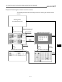
This manual that can be used on a GOT with an operating system installed. These
functions include the utility function, ladder monitor function, system monitor function,
special module monitor function, network monitor function and list editor function.
1.1 Before getting started with various functions
To use in this manual, such as the utility function, ladder monitor function, system
monitor function, special module monitor function, and network monitor function, an
operating system (OS) for each function must be installed first on your GOT by
using drawing software.
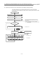
To install an OS for your desired function on your GOT, see SW4D5C-GOTRPACKE(V) Operating Manual (Drawing Software Manual).
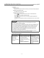
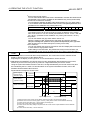
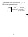
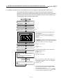
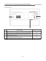
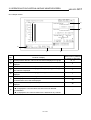
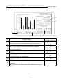
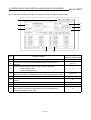
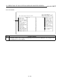
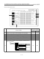
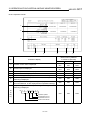
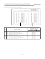
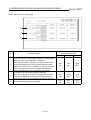
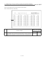
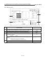
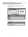
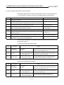
1.2 Precautions before use
Precautions before using each function are described as follows:
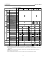
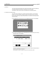
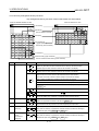
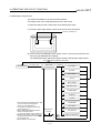
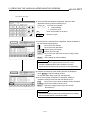
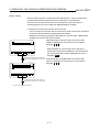
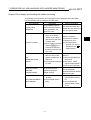
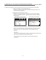
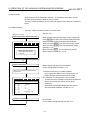
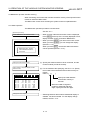
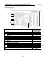
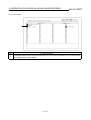
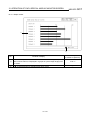
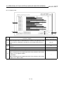
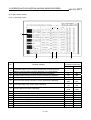
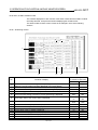
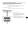
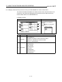
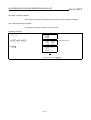
(1) There are unavailable functions depending on the GOT.
Please note that some functions require extension memory in the GOT unit.
Memory is extended according to the following procedures.
For A985GOT/A97*GOT/A960GOT : Memory board is installed in the GOT.
For A95*GOT : A95*GOT-*BD-M3 (memory extension type) is used.
Requirement for
memory extension
Function category
Not required
Basic function
Extension function
Required
Option function
Function
Utility function
System monitor function
Ladder monitor function
Special unit monitor function
Network monitor function
List editor function
A985GOT
A97*GOT
A960GOT
A95*GOT
!
!
!
!
!
×
!
×
!
!
!
!
!: Applicable ×: Not applicable
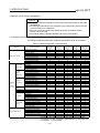
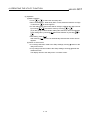
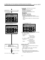
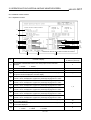
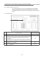
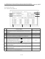
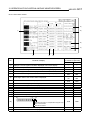
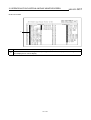
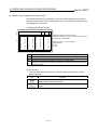
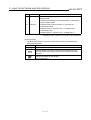
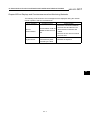
(2) Note that some functions are unavailable depending on the connection target CPU and
connection form. There are the following restrictions on each function depending on the
connection target CPU and connection form.
Refer to Chapter 2 of the GOT-A900 Series User's Manual (SW4D5C-GOTR-PACKE
compatible Connection System Manual) for the connectable CPU names and the access
range for monitoring per connection form.
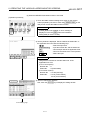
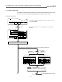
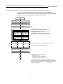
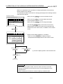
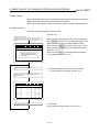
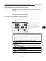
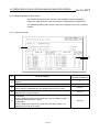
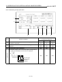
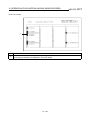
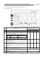
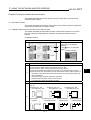
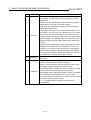
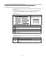
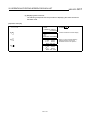
POINTS
(1) Ladder monitoring is not available for sub-programs 2 and 3 of the A4UCPU
(when connected to the computer link).
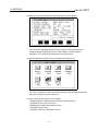
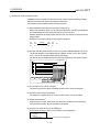
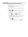
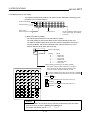
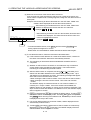
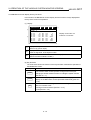
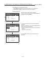
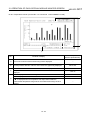
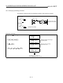
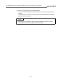
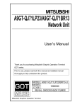
(2) When the monitoring destination is QnACPU, Q4ARCPU, or Q2ASCPU, the
CPU that can perform setup value changes to the timer/counter of the
system monitor function and perform device comment displays, is that the
CPU which ahs "9707 B" and later in the date column of the rated plate.
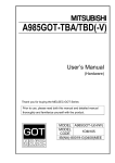
When changing the timer/counter setup value
<Viewing the Rated Plate>
and performing the device comment display,
use the CPU that is described above.
(3) When the GOT is connected to an AnNCPU
or AnACPU, the I/O No. to which a data link
module or network module is installed cannot
PROGRAMMBLE CONTROLLER
be displayed.
(4) When the GOT is connected to an AnNCPU
or AnACPU, a screen display shows a screen
DATE 9707 B
of the MELSECNET II network even when
you are connected to the MELSECNET/10
network (the monitor screen shows the
Date of
Function
display contents of the MELSECNET II).
manufacture version
1-1
1
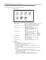
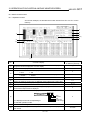
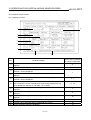
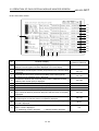
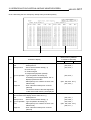
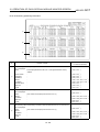
1. OVERVIEW
MELSEC GOT
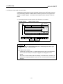
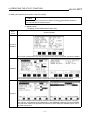
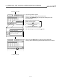
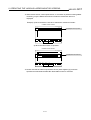
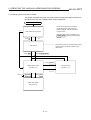
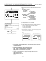
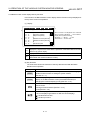
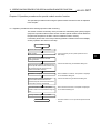
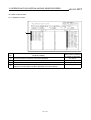
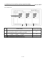
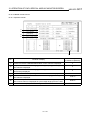
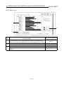
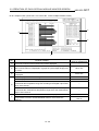
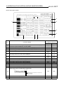
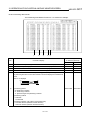
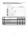
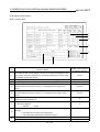
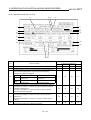
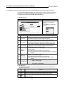
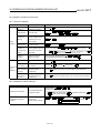
(a) Connection with QCPU
Functions
Brightness/
Adjusting the brightness/contrast
contrast
of a monitor screen
adjustment
Message
display
Selecting a message display.
selection
Copying the screen and OS data
Screen &
between the internal memory and
OS copy
memory card.
Setting a use environment of the
Setup
Utility
GOT
function
Running diagnostic checks on
Self-test
GOT hardware
Memory
Displaying GOT memory
information information.
Clock
Setting the clock.
Screen
cleanup
Displaying the display area
cleanup screen.
Defining a password for limited
access to the utility menu screen.
Sequence program monitoring
using ladder signals
Decimal and hexadecimal display
of word device values
Device comment display
Password
Ladder
monitor
Display
Ladder
switching
monitor
function Device
changing
Print out
Changing of device values
Printing of ladder
Entry
monitor
Monitoring of current values by
pre-registering monitor devices
Monitoring of n points of current
Batch
values subsequent to specified
monitor
device
Monitoring of m points of current
values, set values, contact points,
T/C monitor
and coils subsequent to specified
device
Monitoring of x points of current
values subsequent to specified
BM monitor
buffer memory of specified special
module
System
Setting/resetting of bit device
monitor
function
Changing of current value for
Data
buffer memory of word device
editing
Changing of current value for T/C
using test
(can be used while monitoring
operation
T/C)
Changing of set value for T/C (can
be used while monitoring T/C)
Changing of device values using
Quick test
quick test
Ref.
Section
Bus
connection
CPU direct
connection
QCPU(Q Mode)
Computer
MELSEC
link
NET
connection connection
CC-Link
connection
CPU direct
connection
QCPU(A Mode)
Computer
MELSEC
link
NET
connection connection
CC-Link
connection
Section
4.3
Section
4.3
Section
4.4
Section
4.5
Section
4.6
Section
4.7
Section
4.8
Section
4.9
Section
4.10
Section
6.2.1
∗1
Section
6.2.3
Section
6.2.4
Section
6.2.5
Section
9.2
∗2
∗2
∗3
∗3
Section
9.4
∗2∗4
∗2
Section
9.5
∗2
∗2
Section
9.3
∗2
∗5
Section
9.6
∗2
∗2
∗5
∗2
∗2
∗2
∗2∗6
∗2
∗2∗6
∗2
Section
9.6.2
Device comment display
Decimal and hexadecimal display
of word device values and buffer
memory values
Section
9.1.2
Special module
monitor function
Monitoring of buffer memory of
special module on special screen
Ch. 11
∗2
Network monitor
function
Monitoring of network status of
MELSECNET/B, (II) or /10
Ch. 15
∗2
List editor function
Sequence program in the ACPU is
Ch. 19
list edited.
∗2
Display
switching
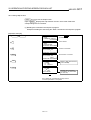
*1 Subprograms 2 and 3 are not possible.
*2 Can be monitored only when the A8GT-J61BT13 is used (in the intelligent device station).
*3 When the A8GT-J61BT15 is used (in the remote device station), only the link devices assigned to the GOT can
be monitored.
*4 The T/C set values cannot be monitored if the software version of the A8GT-J61BT13 used is version W or
earlier.
*5 Can't change V or Z current values.
*6 Cannot be monitored if the software version of the A8GT-J61BT13 used is version W or earlier.
1-2
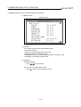
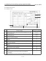
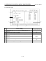
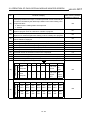
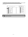
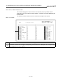
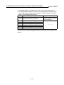
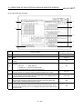
1. OVERVIEW
MELSEC GOT
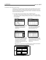
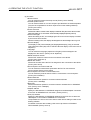
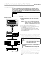
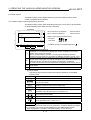
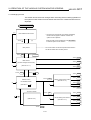
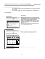
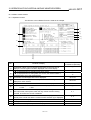
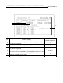
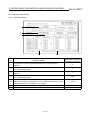
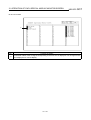
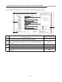
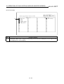
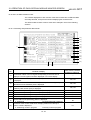
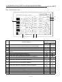
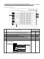
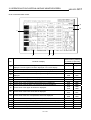
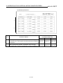
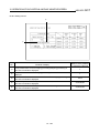
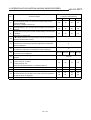
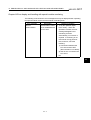
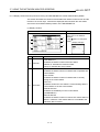
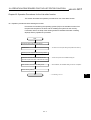
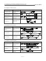
(b) Connection with QnACPU or ACPU
Functions
Brightness/
Adjusting the brightness/contrast
contrast
of a monitor screen
adjustment
Message
display
Selecting a message display.
selection
Copying the screen and OS data
Screen &
between the internal memory and
OS copy
memory card.
Setting a use environment of the
Setup
Utility
GOT
function
Running diagnostic checks on
Self-test
GOT hardware
Memory
Displaying GOT memory
information information.
Clock
Setting the clock.
Screen
cleanup
Displaying the display area
cleanup screen.
Defining a password for limited
access to the utility menu screen.
Sequence program monitoring
using ladder signals
Decimal and hexadecimal display
of word device values
Device comment display
Password
Ladder
monitor
Display
Ladder
switching
monitor
function Device
changing
Print out
Changing of device values
Printing of ladder
Entry
monitor
Monitoring of current values by
pre-registering monitor devices
Monitoring of n points of current
Batch
values subsequent to specified
monitor
device
Monitoring of m points of current
values, set values, contact points,
T/C monitor
and coils subsequent to specified
device
Monitoring of x points of current
values subsequent to specified
BM monitor
buffer memory of specified special
module
System
Setting/resetting of bit device
monitor
Changing of current value for
function
buffer memory of word device
Data
editing
Changing of current value for T/C
using test
(can be used while monitoring
operation
T/C)
Changing of set value for T/C (can
be used while monitoring T/C)
Changing of device values using
Quick test
quick test
Device comment display
Display
Decimal and hexadecimal display
switching
of word device values and buffer
memory values
Ref.
Section
Bus
CPU direct
connection connection
QnACPU
ACPU
Computer MELSEC
Computer MELSEC
CC-Link
Bus
CPU direct
CC-Link
link
NET
link
NET
connection connection connection
connection
connection connection
connection connection
Section
4.3
Section
4.3
Section
4.4
Section
4.5
Section
4.6
Section
4.7
Section
4.8
Section
4.9
Section
4.10
Section
6.2.1
∗2
Section
6.2.3
Section
6.2.4
Section
6.2.5
Section
9.2
Section
9.3
∗1
∗2
∗2
∗2
∗3
∗3
∗2
∗2
Section
9.4
Section
9.5
∗5
Section
9.6
∗6
∗2
∗5
∗2
∗2
∗2
∗1∗6
∗2
∗2
∗2
Section
9.6.2
Section
9.1.2
Special module
monitor function
Monitoring of buffer memory of
special module on special screen
Ch. 11
∗2
∗2
Network monitor
function
Monitoring of network status of
MELSECNET/B, (II) or /10
Ch. 15
∗2
∗2
List editor function
Sequence program in the ACPU is
Ch. 19
list edited.
∗2
*1 Subprograms 2 and 3 are not possible.
*2 Can be monitored only when the A8GT-J61BT13 is used (in the intelligent device station).
*3 When the A8GT-J61BT15 is used (in the remote device station), only the link devices assigned to the GOT can
be monitored.
*4 Can't monitor T/C set values.
*5 Can't change V or Z current values.
*6 If you modified the set value for T/C using the ladder monitor test function, you need to repeat the PC readout
procedure to enable the display of the modification.
1-3
1. OVERVIEW
MELSEC GOT
(c) Connection with FXCPU, third party PLC or microcomputer
Functions
Brightness/
Adjusting the brightness/contrast
contrast
of a monitor screen
adjustment
Message
display
Selecting a message display.
selection
Copying the screen and OS data
Screen &
between the internal memory and
OS copy
memory card.
Setting a use environment of the
Setup
Utility
GOT
function
Running diagnostic checks on
Self-test
GOT hardware
Memory
Displaying GOT memory
information information.
Clock
Setting the clock.
Screen
cleanup
Displaying the display area
cleanup screen.
Defining a password for limited
access to the utility menu screen.
Sequence program monitoring
using ladder signals
Decimal and hexadecimal display
of word device values
Device comment display
Password
Ladder
monitor
Display
Ladder
switching
monitor
function Device
changing
Print out
Changing of device values
Printing of ladder
Entry
monitor
Monitoring of current values by
pre-registering monitor devices
Monitoring of n points of current
Batch
values subsequent to specified
monitor
device
Monitoring of m points of current
values, set values, contact points,
T/C monitor
and coils subsequent to specified
device
Monitoring of x points of current
values subsequent to specified
BM monitor
buffer memory of specified special
module
System
Setting/resetting of bit device
monitor
Changing of current value for
function
buffer memory of word device
Data
editing
Changing of current value for T/C
using test
(can be used while monitoring
operation
T/C)
Changing of set value for T/C (can
be used while monitoring T/C)
Changing of device values using
Quick test
quick test
Device comment display
Display
Decimal and hexadecimal display
switching
of word device values and buffer
memory values
Ref.
Section
FXCPU
CPU direct connection
Other PLC connection
Microcomputer connection
Section
4.3
Section
4.3
Section
4.4
Section
4.5
Section
4.6
Section
4.7
Section
4.8
Section
4.9
Section
4.10
Section
6.2.1
∗1
∗2
∗3
Section
6.2.3
Section
6.2.4
Section
6.2.5
Section
9.2
Section
9.3
Section
9.4
∗4
Section
9.5
Section
9.6
Section
9.6.2
Section
9.1.2
Special module
monitor function
Monitoring of buffer memory of
special module on special screen
Ch. 11
Network monitor
function
Monitoring of network status of
MELSECNET/B, (II) or /10
Ch. 15
List editor function
Sequence program in the ACPU is
Ch. 19
list edited.
*1 When connected to the PLC CPU without clock function (FX0, FX0N, FX1, FX2NC, FX0S), additional function
cannot be set. Also, the clock function can be used with the FX2 and FX2N, when cassette for the realtime clock
is used.
*2 When connected to the PLC CPU without clock function, additional function cannot be set.
*3 You can set the clock function only when you are using A9GT-RS2T, which includes a clock element.
*4 T/C set values and coils cannot be monitored.
1-4
1. OVERVIEW
MELSEC GOT
(3) If a system program (OS) for the expanded or option functions has been installed,
the following space is required in the GOT built-in internal memory to store usercreated monitor screen data. Hence, add the memory board as required.
The installation of an operating system is required for the following expended or
option functions:
• System monitor
1
• MELSEC-ACPU ladder monitor *
1
• MELSEC-FXCPU ladder monitor *
1 2
• MELSEC-QnACPU ladder monitor * *
• Special unit monitor, recipe, sound
• Network monitor
2
• List editor*
3
• ESC printer, bar code, report, external key input *
3
• PCL printer, bar code, report, external key input *
3
• ESC printer, bar code, report, proximity I/O *
3
• PCL printer, bar code, report, proximity I/O *
*1 Any one of the 3 types can be installed.
*2 The memory capacity is different from other OS. It is considered as the
installation of 2 operating systems.
*3 Any one of the 4 types can be installed.
Number of Extended
Memory Space Used
functions OSs
[k bytes]
Free Space [k bytes]
0
0
1152
1
256
896
2
384
768
3
640
512
4
768
384
5
1024
128
6
1152
0
POINT
If the special module monitor function is being used, enough memory space
must be reserved in the internal memory to store the special module monitoring
data (see Section 3.3.3).
1-5
1. OVERVIEW
MELSEC GOT
1.3 Features
The monitor functions described in this manual are intended to improve the efficiency
of trouble-shooting and maintenance operations for the PLC system.
The features of each monitor function are explained in the following sections.
1.3.1 Features of the utility function
The utility function enables you to use GOT setup and self-tests. To use the utility
function, you need to install an operating system for the utility function on the GOT
built-in internal memory by using drawing software. The features of the utility function
are shown below.
(1) The brightness of a monitor screen can be adjusted (see Section 4.3 for details).
(2) The screen and OS data can be copied between the internal memory and memory
card (see Section 4.4 for details).
The data monitored can be copied to and from the GOT built-in internal memory or
a memory card installed on the GOT.
The OS data can only be copied from the GOT to the memory card.
1-6
1. OVERVIEW
MELSEC GOT
(3) Setting a use environment of the GOT (see Section 4.5 for details).
You can set the operating environment of the GOT such as the beep sound,
message display language and screen saver's idle time. When using the
A985GOT, you can also make settings on the Human sensor.
(4) Running diagnostic checks on GOT hardware (see Section 4.6).
You can run diagnostic checks on the GOT hardware, including the image check,
font check, memory card check and so on.
(5) Other functions (see Section 4.7 for details)
• Displaying data on available space in the GOT internal memory.
• Adjusting the clock of the PLC CPU.
• Displaying the display area cleanup screen.
• Changing security levels.
• Limiting access to the Utility Menu screen.
1-7
1. OVERVIEW
MELSEC GOT
1.3.2 Features of the ladder monitor function
Installing the ladder monitor function operating system into the GOT built-in memory
using the drawing software enables ladder monitoring of the PLC CPU program as
shown in a ladder diagram. The features of the ladder monitor function are shown
below.
(1) Monitoring based on ladder symbols (see Section 6.2 for details)
(Sample display)
Ladder monitor screen
STEP : 12345/18374
K
MOV 1
D1
K
MOV 2
D2
P0
M999
187
K
1234
=
D100
MOV
MOV
MOV
K
DUTY 350
D1
D2
1
V
2
D162
47
D167
90
RST
K
90
K
110
K
100
SET
K
400
V
D162
D167
D172
M9028
M9020
D172
110
100
DATA OVERFLOWS ONE SCREEN
Exit
PLCRD.
Mon.
Menu
Print
Screen
List
Cancel
Print
REMARK
The Print Screen and Cancel Print buttons are not displayed on the EL type
screen.
(1) Ladder monitor screen
A maximum of 8 lines (max. 11 contact points per line; with 12 contact points
or more, the line returns) of a sequence program are displayed on one
screen.
Also, for the current values and other settings of word devices, a maximum of
8 devices are displayed (With 9 devices or more, use the arrow keys to switch
displays.).
1-8
1. OVERVIEW
MELSEC GOT
(2) The display format can be changed to show comments for devices (see Section
6.2.2 for details).
(Sample display)
Ladder monitor screen
STEP : 12345/18374
M9036
0
PLS M910
Character string
display
Normally ON
Action
X0001
X0002
4
Ready
display
Y0023
Operation ready
Start
operation
instruction
K25
T0
Operation start
warning
T0
Exit
7
25
PCRD.
Mon.
Menu
Print
Screen
List
Cancel
Print
1) Switching the display format
The current values monitor of the word devices at the bottom of the screen are
executed in decimal or hexadecimal format.
2) Displaying device comments
Comments of for the device used in the PLC program (comments that are
written into the PLC CPU) are displayed.
When comments are displayed, 3 lines of the program are shown.
(3) Monitoring other stations
Other stations in data link systems, network system or CC-Link system, including
the GOT (or stations connected to the GOT), can be monitored.
1-9
1. OVERVIEW
MELSEC GOT
1.3.3 Features of the system monitor function
Installing the screen monitor function operating system into the GOT built-in memory
using the drawing software enables monitoring and testing of the buffer memory for
the PLC CPU program and the special functions module. The features of the system
monitor function are shown below.
(1) Any desired device can be monitored, using 4 dedicated screens
The system monitor function provides an entry monitor, a batch monitor, and a
buffer memory monitor, enabling monitoring of any device, for complete flexibility
in any application.
Entry monitor
Batch monitor
DEVICE MONITOR TEST MENU FORM SET
NETWK No. [ 0]
STATION[FF]
D
D
X
M
Y
W
R
D
15
10
001
25
70
200
50
300
-2147483648
-32767
BATCH MONITOR TEST MENU FORM SET
NETWK No. [ 0]
STATION[FF]
D
D
D
D
D
D
D
D
DW
43
68378428
30000
DW
10
11
12
13
14
15
16
17
32767
0
0
-1
0
3
0
0
D
D
D
D
D
D
D
D
18
19
20
21
22
23
24
25
-500
3234
0
0
0
-32768
0
0
• Up to 8 points for a PLC CPU device
registered by the user can be
monitored in one window (see
Section 9.2).
• Up to 16 points subsequent to a
PLC CPU device specified by the
user can be monitored in one
window (see Section 9.3).
T/C monitor
Buffer memory monitor
TC MONITOR
NETWK No. [ 0]
BM MONITOR TEST MENU FORM SET
NETWK No. [ 0]
STATION[FF]
I/O NO[ 1]
BM 1110 -32767
BM 1118
0
BM 1111
64
BM 1119
0
BM 1112
149
BM 1120
150
BM 1113
-1111
BM 1121
131
BM 1114
126
BM 1122 -32768
BM 1115
160
BM 1123
555
BM 1116
255
BM 1124
2368
BM 1117
1200
BM 1125 11000
TEST MENU FORM SET
STATION[FF]
T
0 PV
0
[Production line
1 PV
0
[Production line
T
2 PV 150
[Production line
T
3 PV
0
[Production line
T
SV
A
SV
B
SV
C
SV
D
0
]
0
]
150
]
0
]
• Up to 8 points, including the current
value, set value, contact point, and
coil can be monitored in a window
subsequent to a PLC CPU timer
(T)/counter (C) specified by the user
(see Section 9.4).
• Up to 16 points subsequent to the
buffer memory of a special function
module specified by the user can be
monitored in one window (see
Section 9.5).
• With the GOT, the full screen can be divided into four windows and separate
monitoring carried out in all four windows simultaneously.
DEVICE MONITOR TEST MENU FORM SET
NETWK No.[ 0]
STATION[FF]
D
D
X
M
Y
W
R
D
15
10
001
25
70
200
50
300
-2147483648
-32767
TC MONITOR
NETWK No.[ 0]
T
DW
43
68378428
30000
DW
TEST MENU FORM SET
STATION[FF]
0 PV
0
[Production line
T
1 PV
0
[Production line
T
2 PV 150
[Production line
T
3 PV
0
[Production line
SV
A
SV
B
SV
C
SV
D
0
]
0
]
150
]
0
]
BATCH MONITOR TEST MENU FORM SET
NETWK No.[ 0]
STATION[FF]
D
D
D
D
D
D
D
D
10
11
12
13
14
15
16
17
32767
0
0
-1
0
3
0
0
D
D
D
D
D
D
D
D
18
19
20
21
22
23
24
25
-500
3234
0
0
0
-32768
0
0
BM MONITOR TEST MENU FORM SET
NETWK No.[ 0]
STATION[FF]
I/O NO[ 1]
BM 1110 -32767
BM 1118
0
BM 1111
64
BM 1119
0
BM 1112
149
BM 1120
150
BM 1113
-1111
BM 1121
131
BM 1114
126
BM 1122 -32768
BM 1115
160
BM 1123
555
BM 1116
255
BM 1124
2368
BM 1117
1200
BM 1125 11000
1 - 10
1. OVERVIEW
MELSEC GOT
(2) Data can be changed by test operation (see Section 9.6 for details).
(Test sample)
When M0 is on
NETWK No.[ 0]
DEVICE[ M] [
STATION[FF]
DEC
0]
RST:0 SET:1[1]
When changing D0 present value
NETWK No.[ 0]
DEVICE[ D] [
STATION[FF]
DEC
0]
VL[ K-2147483648 ]
7
8
9
A
B
7
8
9
A
B
4
5
6
C
D
4
5
6
C
D
1
2
3
E
F
1
2
3
E
F
0
−
!
0
−
!
AC DEL
AC DEL
1) Test for bit device
Device specified by user is turned on or off.
2) Test for word device
Writes designated value into device specified by user.
3) Test for timer/counter
Writes in designated value as current value or set values of device specified by
user.
4) Test for buffer memory
Writes designated value into buffer memory specified by user.
(3) Display format can be changed and device comments can be displayed (see
Section 9.1.2 for details).
(Sample display)
For entry monitor
(comment display)
For batch monitor
(hexadecimal display)
DEVICE MONITOR TEST MENU FORM SET
NETWKNo.[ 0] STATION[FF]
BATCHMONITOR TEST MENU FORM SET
NETWK No.[ 0] STATION[FF]
D
W
R
X
200
30
[Line 1 current units ]
200
43
[Production line A
]
50
68378428 DW
[link status
]
3
[Input switch 3
]
D
D
D
D
D
D
D
D
10
11
12
13
14
15
16
17
H
H
H
H
H
H
H
H
7FFF
0000
0000
FFFF
0000
0003
0000
0000
D
D
D
D
D
D
D
D
18
19
20
21
22
23
24
25
H
H
H
H
H
H
H
H
FE0C
0CA2
0000
0000
0000
8000
0000
0000
1) Changing display format
The word device values for the entry monitor, batch monitor, T/C monitor, and
the buffer memory monitor are monitored in decimal or hexadecimal format.
2) Device comment display
When the PLC CPU device is monitored, the comments written into the PLC
CPU are displayed.
(4) Other stations can be monitored.
Other stations in data link systems, network systems or CC-Link systems,
including the GOT (or stations connected to the GOT), can be monitored.
1 - 11
1. OVERVIEW
MELSEC GOT
1.3.4 Features of the special module monitor function
Installing (or downloading) the special module monitor function operating system and
special module monitor data into the GOT built-in memory using the drawing software
enables monitoring and changing of data in the special function module buffer
memory, using dedicated screens.
Signal statuses of I/O modules can also be monitored.
The features of the special module monitor function are shown below.
(1) Monitoring can be done with dedicated screens (see Section 12.2 for details).
Monitoring is carried out using dedicated screens provided by the manufacturer
for the special function module and I/O module.
It is not necessary for the user to create monitor screens.
(Sample display 1: for special function module)
Menu screen after module
Monitor screen after menu
selection
selection
A68RD
Graph monitor screen
*********
87654321
0000000000000000
1:*** 0:***
600
500
1 Operation Monitor
2 I/O Monitor
3 Graph Monitor
Menu
selection
400
* 300
*
[°C] 200
100
0
-100
-180
1
******
******:
0
2
3
4
********
0
0:**JIS.DIN
5
1:**JIS
6
7
8
*********
87654321
0000000000000000
1:*** 0:***
******/******
****/****
8765432187654321
0000000000000000
1:********************
0:********************
CH1********
CH2 ″
CH3 ″
CH4 ″
CH5********
CH6 ″
CH7 ″
CH8 ″
(Sample display 2: for I/O module)
Monitor screen
X MODULE
X
X
040
041
042
043
044
045
046
047
048
049
04A
04B
04C
04D
04E
04F
"
#
#
#
"
"
#
"
#
#
#
#
#
#
#
#
050
051
052
053
054
055
056
057
058
059
05A
05B
05C
05D
05E
05F
#
#
#
#
#
#
#
#
#
#
#
#
#
#
#
#
060
061
062
063
064
065
066
067
068
069
06A
06B
06C
06D
06E
06F
"
"
"
"
"
"
#
#
#
#
#
#
#
#
#
#
070
071
072
073
074
075
076
077
078
079
07A
07B
07C
07D
07E
07F
#
#
#
#
#
#
#
#
#
#
#
#
#
#
#
#
1) Menu screen
The menu is displayed classified into monitor items for the special function
module only.
The object monitor screen is displayed by selecting the item from the menu.
2) Monitor screen
With the special function module, the buffer memory contents and the status
of the PLC CPU I/O signals are monitored using text, numbers, and graphs.
With the I/O module, the status of I/O signals to and from an external module
is monitored.
1 - 12
1. OVERVIEW
MELSEC GOT
(2) Data can be changed by writing (see Section 12.1.5. for details).
(Writing example)
Monitor screen
A68RD
Graph monitor screen
500
400
* 300
*
200
[°C]
100
0
-100
-180
1
0
2
3
4
********
0
0:**JIS.DIN
5
1:**JIS
6
7
8
*********
87654321
0000000000000000
1:*** 0:***
******/******
****/****
8765432187654321
0000000000000000
1:********************
0:********************
CH1********
CH2 ″
CH3 ″
CH4 ″
Parameter Data Monitor Screen
X∗∗ Y∗∗
*********
87654321
0000000000000000
1:*** 0:***
600
******
******:
When changing channel that can be changed
AD71
Menu
selection
Y10 Y11 ∗∗∗∗∗∗∗∗∗∗
Y12 ∗∗∗∗∗
X02 X03 ∗∗∗∗∗∗∗∗∗∗
X06 X07 ∗∗∗∗∗∗∗∗∗∗
Y13 Y14 ∗∗∗∗∗∗∗
X0C X0D ∗∗∗∗∗∗
Y17 Y19 ∗∗∗∗∗∗∗∗
Y1B Y1A ∗∗∗∗∗∗∗
Y15 Y16 ∗∗∗∗
X08 X09 ∗∗∗∗
X04 X05 RUSY
X0E X0F ∗∗∗∗
CH5********
CH6 ″
CH7 ″
CH8 ″
X00 ∗∗∗∗∗∗∗∗
X0A ∗∗∗∗∗∗∗∗
X0B ∗∗∗∗∗∗∗∗
X∗∗
Y∗∗
X∗∗
ABCDDEFF
0000000011110100
∗∗∗∗∗∗∗∗∗∗∗∗∗
∗∗∗∗∗∗∗∗∗∗
1
1
1
1
∗∗∗∗∗∗∗∗∗∗∗∗∗
∗∗∗∗∗∗∗∗∗∗
120
120
120
120
1000
1000
-6
2550
7
8
9
0 100
4
5
6
−
1
2
3
!
0
0
0DEL
300
0 70
100
0
0
0
300
0 70
Y∗∗
ABCDDEFF
0000000011110100
A:∗∗∗∗∗∗∗∗∗∗∗∗∗∗∗∗
0:R∗∗∗ 1:A∗∗∗
B:M∗∗∗∗∗ON/OFF
0:NO
1:YES
C:M∗∗∗∗∗∗∗∗∗∗
0:NO
1:YES
DD:∗∗∗∗∗∗∗∗∗∗
00:ABS 01:INS
10:ABS+INS
E:∗∗∗∗∗∗∗∗∗∗∗∗∗∗∗∗
0:∗∗∗∗ 1:∗∗∗∗
F:∗∗∗∗∗∗∗∗∗∗∗∗∗∗∗∗
00:∗∗∗ 01:∗∗∗
10:∗∗∗ 11:PLS
1) The designated values are written into the user-specified buffer memory by
writing the values from the monitor.
2) When changing the buffer memory data, input the numeric value using the auto
display key window and write it into the buffer memory.
(3) Special module monitor data can be allocated as user monitor screen data.
The special module monitor data installed in the computer can be allocated to
serve as user monitor screen data. To do this, the steps below are required.
1) Using the Copy function, allocate special module monitor data from another
project as user monitor screen data.
2) Correct the data to match the system used for the BM initial buffer memory
number of the sprite function which has been set.
1 - 13
1. OVERVIEW
MELSEC GOT
1.3.5 Features of the network monitor function
To use the network monitor function, you first must install an operating system (OS)
for the network monitor function on your GOT by using drawing software. This enables
you to monitor the status of the MELSECNET/B, MELSECNET (II), and
MELSECNET/10 networks. The following describes the features of the network
monitor function.
(1) Network monitor screens are selectable on the own station monitor screen to
monitor the own station and other stations on a network.
The own station monitor screen enables you to monitor the status of all the
network lines connected to the own station.
A touch of the screen will guide you through various monitor screens to monitor
the status of the own station and other stations on a network.
(2) Network information can be obtained from the own station monitor screen.
Dedicated monitor screens are available for each category of station classification,
depending on the role that is played by the own station.
Network category: MELSECNET/B, MELSECNET (II) master station
MELSECNET/B, MELSECNET (II) local station
MELSECNET/10 control station/ordinary station
MELSECNET/10 remote master station
(Sample display) MELSECNET/B, MELSECNET (II) master station
1 - 14
1. OVERVIEW
MELSEC GOT
(3) The status of other stations can be monitored on the other-station monitor screen.
The other-station monitor screen provides the following type of information on the
status of other stations connected on a network:
• Communications status of each station
• Data link status of each station
• Parameters status of each station
• CPU action status of each station
• CPU RUN status of each station
• Loop status of each station
(Sample display) Other station monitor menu screen
Other station's communications status monitor screen
1 - 15
1. OVERVIEW
MELSEC GOT
1.3.6 Features of the List editor function
Installation of the List editor function OS into the memory with the drawing software
allows for list edit of the sequence program in the ACPU.
The following shows features of the List editor function.
(1) Easy parameters and sequence program maintenance
Simple key operations allow checks, partial modifications, changes and additions
of the parameters and the sequence program in the PLC CPU.
Without peripheral equipment other than the GOT, the sequence program can be
simply edited.
Example of command change in the sequence program
LD
OUT
LD
X0
Y20
X1
LD
X0
MOV D0
LD
X1
Change
D1
(2) Interlock with the ladder monitor function (only when A985/97*/960GOT is used)
The list edit window can be started from the ladder monitor screen with a single
touch. The list can be edited while viewing the ladder.
The list can also be displayed from the step line displayed on the ladder monitor.
P0
STEP : 12345/18374
K
MOV 1
D1
K
M999
187
K
1234
=
D100
R 187
188
193
198
LD M999
List
D1
MOVK1
AND =K123 D100 EDITOR
D2
MOVK1
READ
INSERT
FROM
A
B
B
TO
C
D
D
PARAM
OTHER
INC
E
F
F
*
G
/
H
CALL
I
RET
J
DEC
K
MRD
L
MOV
M
SHIFT WRITE DELETE
D1
D2
1
Exit
V
2
PLCRD.
D162
47
Mon.
D167
90
Menu
Print
Screen
>
N
<
O
P
P
_
Q
MPP
R
S
T
BCD
U
BIN
V
W
W
MPS
X
LD
C
AND
D
OR
E
MC
F
MCP
W
END
Z
LDI
8
ANI
9
ORI
A
MCR
B
Ý è
’
(
SET
4
ANB
5
ORB
6
PLS ƒ
N ƒ
Š ƒ
A
7
«
(¨ )
RST
0
SFT
1
CJ
2
OUT
3
GO
D167 +
110
List
Cansel
Print
HELP
SP
)
(3) The list edit screen can be recorded.
The hard copy function allows recording the edit screen of the list program.
(4) Access to other station is available.
The sequence program of the PLC CPU in other station can be list edited.
(5) Useful help functions
Help functions for read, write, insert and delete are available on the interactive
menu selection system. Simple operation is facilitated.
(6) Comment for each device can be displayed.
Comment of the device at the cursor position can be displayed.
W
M50
9 OUT
1 0 MOV
10
D1
Current value
Comment of D1 is displayed.
1 - 16
2. BEFORE BEGINNING OPERATION
MELSEC GOT
Chapter2 Before beginning operation
The required equipment for using the monitor functions in this manual are described in
this section.
2.1 Required equipment
2
The chart below shows the equipment required for using the monitor functions.
!: Required
Required
equipment
GOT main unit
(A95*GOT*BD-M3)
Memory
board *1
PLC drawing
software *2
Connecting
cables *2
Application
Utility
• It is required to use the option function
installed on the A95*GOT.
• It is required to use the option function
installed on the A985/97*/960GOT.
• Required for installing the object
monitor function OS into the GOT and
downloading the special module
monitor data.
• It is necessary to install the drawing
software into the PLC.
• Required for connecting the above
PLC and the GOT when installing the
object monitor function OS into the
GOT and downloading the special
module monitor data.
×
Ladder
monitor
×
Special
function
module
monitor
System
monitor
×: Not required
Network
monitor
List
editor
!
!
×
×
!
!
!
!
*1 The table below shows the types of memory boards available for using the option functions.
Name
Model
Memory board for option
A9GT-FNB
functions
Contents
For option function (applicable for A/FX ladder
monitor)
A9GT-QFNB
For option function (applicable for QnA/A/FX ladder
monitor)
Expanded memory board
A9GT-FNB1M
for option functions
Option function (applicable for A/FX ladder monitor) +
internal memory extension 1MB
A9GT-FNB2M
Option function (applicable for A/FX ladder monitor) +
internal memory extension 2MB
A9GT-FNB4M
Option function (applicable for A/FX ladder monitor) +
internal memory extension 4MB
A9GT-FNB8M
Option function (applicable for A/FX ladder monitor) +
internal memory extension 8MB
A9GT-QFNB4M
Option function (applicable for QnA/A/FX ladder
monitor) + internal memory extension 4MB
A9GT-QFNB8M
Option function (applicable for QnA/A/FX ladder
monitor) + internal memory extension 8MB
*2 For information about the PLC on which to install and use drawing software and the
cable to be connected between the PLC and the GOT, see SW4D5C-GOTRPACKE(V) Operating Manual.
2-1
2. BEFORE BEGINNING OPERATION
MELSEC GOT
MEMO
2-2
3. SPECIFICATIONS
MELSEC GOT
Chapter3 Specifications
In this chapter, the specifications of the ladder monitor function, system monitor
function, special module monitor function, and list editor function are discussed
separately.
3
3.1 Ladder monitor function specifications
POINTS
• When the ladder monitor function is used on the A985/97*/960GOT, the
memory board applicable for the PLC CPU at the monitoring destination.
• The ladder monitor function cannot be used on the A95*GOT.
3.1.1 PLC CPUs to be monitored
The PLC CPUs that allow ladder monitoring are the QCPU (A Mode), QnACPU,
ACPU, FXCPU and motion controller CPU. For details, refer to Section 1.2 (2).
POINT
Ladder monitoring is not available for sub-programs 2 and 3 of A4UCPU (when
connected to the computer link).
3.1.2 Access ranges to be monitored
For access range for the ladder monitor function, see GOT-A900 Series User’s
manual (SW4D5C-GOTR-PACKE compatible Connection system manual).
POINT
• When the capacity of parameter, PLC program, TC setting value, comment
and extension comment is 144 kbytes or more, the comment will not be
properly displayed.
• The local device cannot be monitored on the QnACPU.
3-1
3. SPECIFICATIONS
MELSEC GOT
3.2 System monitor function specifications
3.2.1 PLC CPUs to be monitored
The PLC CPUs that allow system monitoring are the QCPU, QnACPU, ACPU,
FXCPU and motion controller CPU. For details, refer to Section 1.2 (2).
3.2.2 Access ranges to be monitored
For access range for the system monitor function, see GOT-A900 Series User’s
manual (SW4D5C-GOTR-PACKE compatible Connection system manual).
3.2.3 Names of devices to be monitored
For the names of devices that can be monitored with the system monitor function, see
GOT-A900 Series User’s manual (SW4D5C-GOTR-PACKE compatible Connection
system manual).
3.2.4 Precautions when using the system monitor function
The precautions to follow when using the system monitor function are shown below.
(1) Monitor and test of real number data
Real number data cannot be monitored or tested.
Monitoring of word devices that save real number data is all done by integer data
(binary data).
(2) Monitoring in 32-bit modules
When monitoring word devices (such as T, C, D, W) in 32-bit (2-word) modules,
monitor up to the point where 32 bits remain in the monitor processing. A location
where 16 bits (1 word) remain cannot be monitored.
This situation occurs when an odd number has been specified as the initial number
in the monitor device.
(Example) When monitoring the A2NCPU data register in 32-bit modules
beginning with an odd number (D1, D3...)
1017
1018
1019
1020
Monitor display module
3-2
1021
1022
1023
Nothing displayed
3. SPECIFICATIONS
MELSEC GOT
(3) The "Date" column of a Rated Plate shows the date manufactured and function
version number. If it reads "9707 B" or a later notation, timer/counter settings can
be changed and device comments can be displayed when using any of the largescale QnACPUs or small-scale QnACPUs.
When changing the timer/counter setup value and performing the device comment
display, use the CPU that is described above.
<Viewing the Rated Plate>
PROGRAMMBLE CONTROLLER
DATE 9707 B
Date of
Function
manufacture version
3-3
3. SPECIFICATIONS
MELSEC GOT
3.3 Special module monitor function specifications
POINTS
• The memory board is required to use the special unit monitor function on the
A985/97*/960GOT.
• The special unit monitor function cannot be used on the A95*GOT.
3.3.1 Access ranges to be monitored
(1) When using bus connection/CPU direct connection/computer link connection
! The special function modules on the bases of the connected station and other
stations can be monitored.
(2) When using MELSECNET(II) connection/MELSECNET/B connection
! The special function module on the base of the master station can be monitored.
(Cannot be monitored when the master station is the QnACPU.)
! The special function modules on the bases of local stations cannot be monitored.
(3) When using MELSECNET/10 connection
! The special function modules on the bases of the control station and normal
stations can be monitored.
(Cannot be monitored when the stations are the QnACPU.)
(4) When using CC-Link connection (remote device station)
! The special function modules cannot be monitored.
(5) When using CC-Link connection (intelligent device station)
! The special function modules on the bases of the master and local stations can
be monitored.
(6) When using the system configuration where remote I/O stations exist
! The special function modules cannot be monitored in any connection form.
3.3.2 Special function modules to be monitored
The modules for which special function monitoring can be done are only those types
shown in Section 3.3.3.
Monitoring of special function modules other than those can be done with the system
monitor function "BM Monitor".
3-4
3. SPECIFICATIONS
MELSEC GOT
3.3.3 Memory capacity required for using the special module monitor function
The memory capacity required when saving special module monitor data to the GOT
built-in memory and the memory capacity required when saving to a Personal
computer hard disk are shown below.
(Unit: kilobytes)
Software to be saved
Special module monitor data
Memory capacity required
when saving to a personal
computer hard disk
Memory capacity required
when saving to GOT built-in
memory
13.4
A61LS
14.5
AD61
8.14
A62DA-S1
6.91
A62LS
69.8
A68AD(S2)
9.97
A68ADN
15.0
A68RD3
A68RD4
A616AD
A616DAI
A616DAV
A616TD
123
33.5
20.5
29.3
AD71(S1/S2/S7)
546
AD75P1(P2/P3)*1
A1SD75P1(P2/P3)*2
AJ71PT32-S3
AJ71ID1(ID2)-R4
A1SJ71ID1(ID2)-R4
562
520
43.5
20.2
A1SD61
36.9
A1S62DA
5.12
A1S62RD
12.5
A1S63ADA
16.4
A1S64AD
12.3
A1S68AD
9.75
A1S68DAV
40.5
A84AD
A1S68DAI
By merely downloading either,
both sides can be monitored.
230
AD70D
A1SD71-S2(S7)
17.8
AD70
AD72
Remarks
25.8
A1SD70
21.1
A1SJ71JPT32-S3
43.2
A1S64TCTT/RT-S1
45.7
Input module
0.0
Output module
0.0
*1 The AD75M1(M2/M3) can be monitored within the monitoring range of the AD75P1(P2/P3).
*2 The A1SD75M1(M2/M3) can be monitored within the monitoring range of the A1SD75P1(P2/P3).
3-5
By merely downloading either,
both sides can be monitored.
3. SPECIFICATIONS
MELSEC GOT
3.3.4 Precautions when using the special module monitor function
The precautions to follow when using the special module monitor function are
discussed below.
(1) Special function modules that cannot be monitored
Modules displayed as "special" on the system configuration screen cannot be
monitored using the special module monitor function.
To monitor these modules, use the system monitor function "BM Monitor".
(2) Display when connecting the small building-block type PLC CPU
This precaution pertains to a situation where an expansion base unit for a large
building block type of setup is connected to a small building-block type CPU (such
as the A1SCPU) in a station connected to the GOT.
In such a case, the special function module on the large expansion base unit is
displayed on the system configuration screen with the same model name as that of
the small building-block type special function module.
If there is no small building-block type special function module, "special" is
displayed and the object module cannot be monitored.
(Example)
[Module Model]
AD72
AJ71ID
AJ71PT32-S3
AD75P
A68AND
A68RD
[Model Name Displayed]
A1SD71
A1SJ71ID
A1SJ71PT32-S3
A1SD75P
A1S64AD
A1S62RD
(3) Monitoring restricted special function modules
(a) When monitoring the AD71 (S1, S2, S7)
When the slot on front of the AD71 module is an empty slot, monitoring is done
in the following way.
1) The AD71 is treated as the AD72, and "AD72" is displayed on the system
configuration screen.
In this case, when monitoring the AD71, select the AD72 in the object
display position.
2) The monitor screen that is displayed by 1) above is for the AD72.
The number obtained by subtracting 10H from the I/O signal number on the
display is the number to be used when installing the AD71 in the 0 slot.
∗ If you do not want the AD1 to be treated as the AD72, execute "Shift the
installation position of AD71 forward" or "In the I/O assignments, assign
the empty slot in front of AD71 to the 16 X-Y points."
(b) When monitoring the A68AD installed in the small building-block type PLC CPU
With the GOT, the A68AD that is installed in the expansion base unit for the
building-block type setup connected to the small building-block type CPU (such
as the A1SCPU) is recognized as the A1S68AD and monitored as such.
Since the buffer memory composition of the A68AD and the A1S68AD is not
the same, different data is displayed on the screen when monitoring the
A68AD(displayed as the A1S68AD).
∗ An A68AD that is installed in the base unit of the building-block type PLC
CPU (such as the AnUCPU) can be monitored normally.
3-6
3. SPECIFICATIONS
MELSEC GOT
(c) When monitoring the A1SD75M, AD75M
The A1SD75M/AD75M is displayed as A1SD75P/AD75P.
The A1SD75M/AD75M can be monitored within the monitoring range of the
A1SD75P/AD75P.
(d) When monitoring the A81CPU
The A81CPU is monitored in the following way.
64 points in first half
Treatment of A81CPU
64 points in last half
Change to module that cannot be
Change to input module.
monitored.
System configuration
Display "Special X, Y
screen
Possibility of monitoring
"
Display "Input 64 X
Not possible
"
Can be monitored as input.
(e) When monitoring an I/O composite module
1) With an I/O composite module for which "Output
" is displayed on the
system configuration screen, only the output signal can be monitored.
For the input signal, monitor X of the PLC CPU device with the system
monitor function.
(4) Editing and allocating of special module monitor data
Data displayed on a special module monitor screen cannot be edited by modifying
or adding an object, except that the data can be used on a user-created monitor
screen.
(5) Precaution for I/O allocation setting
(a) When the QnACPU is connected, the head XY numbers are displayed in due
order on the special module monitoring system configuration screen if the I/O
allocation setting is random as shown below.
When performing special module monitoring, always perform the I/O allocation
in order from slot 0.
QnA
CPU
0
1
Input
32
points
Input
32
points
0
200
2
3
4
5
Input AD75 A68AD Output
special special
32
32
32
points
32
points
points points
20
220
40
6
7
Open
Open
240
Slot number
Head XY number
Set randomly
GOT system configuration screen
Input
32
Input
32
Input
32
0
20
40
Special Special
Input
CPU
60
80
A0
Module name not displayed.
(b) If the slot assigned to Output in I/O allocation is not fitted with a module, the
GOT displays Input. (Common to ACPU and QnACPU)
(6) The system configuration including remote I/O stations cannot be monitored.
3-7
3. SPECIFICATIONS
MELSEC GOT
3.4 Network monitor function specifications
POINTS
• The memory board is required to use the network monitor function on the A985
/97*/960GOT.
• The A95*GOT-*BD-M3 (memory extension type) is required to use the network
monitor function on the A95*GOT.
• When the connection target is the QCPU (Q mode), the network monitor
function cannot be used.
• The network status of the MELSECNET/10H cannot be monitored.
3.4.1 Network information to be monitored
The following table shows the types of network information that can be monitored.
Table 3.1 Network Information To be Monitored
Function
Own station monitor
Own station
information
Controlstation
information
Detailed
own
station
monitor
Data link
information
Constant link
scan
BWY receive
BW receive
Loopback
Own station
status
Other station monitor
Network Information
Network category display
Network No. display
Station No. display
Own station operation mode
Own station loop line status
Loop back execution status
Link scan time display
Data link system loop status
Own station communications status
Own station's station No.
Own station
Network No.
Group No.
Specified control station
Current control station
Communications information
Sub-control-station link
Remote-I/O-master-station station No.
Total of linked stations
Largest connected station
Largest data-linked station
Communications status
Causes of interrupted communications
Causes of data link stoppage
Constant link scan
BWY from the master station
BW from the master station in the higher loop
F-loop status
R-loop status
F-loopback station
R-loopback station
Loop switching frequency
Parameter settings
Designation of reserved stations
Communications mode
Designation of transmission
Transmission status
Communications status of each station
Data link status of each station
Parameter status of each station
CPU action status of each station
CPU RUN status of each station
Loop status of each station
MELSECNET
(II)/B Master
Station
MELSECNET
(II)/B Local
Station
MELSECNET
/10 Control
Station
MELSECNET
/10 Ordinary
Station
MELSECNET
/10 Remote
Master Station
!
!
!
!
!
!
!
!
!
!
!
!
!
!
!
!
!
!
!
!
!
!
!
!
!
!
!
!
!
!
!
!
!
!
!
!
!*1
!
!
!
!
!
!
!
!
!
!
!
!
!
!
!
!
!
!
!
!
!
!
!
!
!
!
!
!
!
!
!
!
!
!
!
!
!
!
!
!
!
×
×
×
×
×
×
×
×
!
!
×
×
×
×
×
×
×
!
×
×
×
×
×
×
×
×
!
!
!
!
!
×
×
×
×
×
!
!
!
!
!
!
×
×
×
×
×
×
×
×
×
×
!
×
×
!
×
×
×
!
!
!
!
×
×
×
×
×
×
×
×
×
×
×
!
!
×
×
×
!*2
!*2
!*2
!*2
!*2
!
!
!
!*2
!*2
!
!
!
!
!
!*2
×
×
!*2
!*2
!*2
!*2
!*2
!
!
!
!*2
!*2
!
!
!
!
!
!*2
×
×
×
×
×
×
×
×
!*2
!*2
!*2
!*2
!*2
×
!
!
!*2
!*2
!
!
!
×
×
!*2
*1 Accessible only when connected to a MELSECNET(II) local station.
*2 Accessible only when connected to a MELSECNET/10 optical fiber cable.
!: Accessible ×: Not accessible
3-8
3. SPECIFICATIONS
MELSEC GOT
3.4.2 Access ranges to be monitored
For access range for monitoring, see Chapter 2 of the GOT-A900 Series User’s
manual (SW4D5C-GOTR-PACKE compatible Connection system manual).
3.4.3 Precautions when using the network monitor function
The following describes precautions that should be followed when using the network
monitor function.
(1) When the GOT is connected to an AnNCPU or AnACPU, a screen display shows a
screen of the MELSECNET II network even when you are connected to the
MELSECNET/10 network (the monitor screen shows the display contents of the
MELSECNET II).
(2) There may be a possibility that the network monitor function cannot be used,
depending on which CPU to connect and which connection method to use.
Network Monitor Function
CPU to Be
Connected
Connection Method
Own Station
Monitor
QCPU,
Bus connection
QnACPU,
Direct CPU connection
ACPU,
MELSECNET connection *1
Motion
Computer link connection *2
Detailed Own
Station
Monitor
Other Station
Monitor
!
!
!
×
×
×
controller
cpu
FXCPU
CC-Link connection
CPU direct connection
Other manufacture’s PLC
*1 When connected to a QnACPU, control and master stations cannot be monitored.
*2 When connected to an AnUCPU, monitoring cannot be done with the
MELSECNET/10 network card being installed.
(3) When connected to a QnACPU, monitoring cannot be done with the keyword being
defined.
3-9
3. SPECIFICATIONS
MELSEC GOT
3.5 List editor function specifications
POINTS
• To use the List editor function on the A985/97*/960GOT, the memory board is
required.
• To use the List editor function on the A95*GOT, the A95*GOT-*BD-M3
(memory extension type) is required.
3.5.1 PLC CPU that allows for list edit
PLC CPUs that allow list edit are either the QCPU(A mode) or the ACPU.
For details, refer to section 1.2 (2) (a).
POINT
• With the computer link connection, the above PLC CPUs do not allow use of
the List editor function.
• In using the A2USH-S1/A2SH-S1/A2SH/A1SH/A1SJHCPU, the following
restrictions should be observed in the range of list edit.
In using the A2USHCPU-S1
: In the range of the A3UCPU
In using the A2SH-S1/A2SH/A1SH/A1SJHCPU : In the range of the A3NCPU
3.5.2 Access range that allows for list edit
For information about the access range that allows for list edit, see Chapter 2 of the
GOT-A900 Series User's manual (SW4D5C-GOTR-PACKE compatible Connection
system manual).
3.5.3 Precautions for List editor function
Precautions for the List editor function are as follows:
(1) Precaution for reading with the specified command
The command cannot be specified to read the ladder.
(2) Precaution for use with the ladder monitor function
If list edit is performed while the ladder monitor function is started, the edit details
are not shown on the ladder monitor screen.
To show the edit details, the ladder monitor must be read from the PLC again.
(3) Precaution for list edit
While the corresponding PLC is at stop status, perform list edit.
The list cannot be edited during PLC running.
(4) Precaution for parameter changing on the other peripheral device
If parameter settings are changed on the other peripheral device during use of the
list edit function, they will be different from the settings of the internal parameters of
the list edit function.
For this reason, reset the GOT unit or make PC No. setting again to read the
parameters.
3 - 10
3. SPECIFICATIONS
MELSEC GOT
3.5.4 List of key arrangement and key functions
Key arrangement and key functions of the list edit window are shown below.
When the A985/97*/960GOT is used
When the A95*GOT is used
1) Control key
List EDITOR
List
EDITOR
SHIFT
READ INSERT
WRITE DELETE
PARAM
OTHER
B
B
TO
C
D
D
INC
E
F
F
*
G
/
H
CALL
I
RET
J
DEC
K
MRD
L
MOV
M
>
N
<
O
P
P
=
Q
MPP
R
+
S
T
BCD
U
BIN
V
W
W
MPS
X
LD
C
AND
D
OR
E
MC
F
NOP
Y
END
Z
LDI
8
ANI
9
ORI
A
MCR
B
SET
(
)
SET
4
ANB
5
ORB
6
PLS
7
CLEAR
(
)
RST
0
SFT
1
CJ
2
OUT
3
SP
1)
Name
SHIFT
3) Help key
HELP
FROM
A
No.
2) Mode key
(key for selection of mode)
4) Command key
(upper character)
Device key (lower character)
READ
WRITE
INSERT
DELETE
SET
PARAM
OTHER
HELP
GO
FROM
A
B
B
TO
C
D
D
INC
E
F
F
*
G
/
H
CALL
I
RET
J
DEC
K
MRD
L
MOV
M
>
N
<
O
P
P
=
Q
MPP
R
+
S
T
BCD
U
BIN
V
W
W
MPS
X
NOP
Y
END
Z
LDI
8
ANI
9
ORI
A
MCR
B
LD
C
AND
D
OR
E
MC
F
CLEAR
RST
0
SFT
1
CJ
2
OUT
3
SET
4
ANB
5
ORB
6
PLS
7
SP
GO
Key
General description of function
Key that declares start of step number input or automatic scroll.
Switch key that makes the lower character valid on each key with dual functions.
Whether upper or lower character is valid can be checked on the display.
Switch key that makes the upper character valid on each key with dual functions.
Whether upper or lower character is valid can be checked on the display.
If the Clear key is pressed when the system is not in the Parameter mode, Other mode or
Help function, the screen returns to the initial status of the mode selection.
(The input commands or device numbers except for the mode are cleared.)
This is used for repeating the procedure if incorrect keys are pressed.
SHIFT
CLEAR
In the Parameter mode, the process is cancelled. After restarting, continue the operation.
In the Other mode, the screen returns to the previous display.
When the Help function is used, the screen returns to the display at the input of the
HELP key.
SP
Key that provides blank space at the command and at between device names.
) , (
)
3)
Help key
4)
Command key
Advice key
READ
WRITE
to
Key that moves the cursor on the display (
PARAM
OTHER
Command key
Device
No./Constant
setting key
) or determines scroll directions.*
HELP
Key that selects each mode of the List editor function.
Switch the upper/lower character mode with the
SHIFT key.
Key that selects the help function in the mode supporting the help function.
Key that inputs K/H at the input of command, device name and constant input.
FROM to END
A
Z
Only when the valid key of upper/lower character needs to be switched, switching is
allowed with input of the
5)
,
Press this key at the last of a series of key operations to execute the operation.
Check the details of key operations on the display before pressing this key.
GO
Mode key
)
5)Command key (upper character)
Device number/constant set key (lower character)
SET
2)
)
(
1) Control key
Control key
(
(
SHIFT and SET keys.
Key that inputs the command, device number and constant.
RST to
0
MC
F
Only when the valid key of upper/lower character needs to be switched, switching is
allowed with input of the
3 - 11
SHIFT and SET keys.
3. SPECIFICATIONS
MELSEC GOT
* Movement of the cursor key between steps, between the menu items and in the
input area is explained below.
(1) Keep pressing the cursor key to repeat the movement toward the specified key
direction.
(2) Movement between steps and between menu items
To display the program immediately before/after the current step number
command, Input either
or
key.
: Program immediately before the command (no change after 0 step)
: Program immediately after the command (no change after the last step)
R
"
0
1
2
3
L D
A N D
O U T
K 1 2 3
X 0 0 0 5
M 2
T 0
" moves to the specified direction (upward/downward) with
or
key.
(3) Movement in the input area
To move the cursor between command names, between sources, and between
destinations, input either
W
P
1
1
1
K
1
2
2
2
(
)
or
(
)
key.
5
M 5
0
L D
M 3
1
N 0 P
1 4 7 4 8 3 6 4 7
D 1 0 0 0
Input area
Display example for DWOVP K2147483647 D1000
"
" moves to the specified direction (left/right) with
3 - 12
(
)
or
(
)
key.
3. SPECIFICATIONS
MELSEC GOT
In this operating manual, the List editor function key is represented in the following
abbreviation form.
(1) Expression of Key 1
Key 1 to Key n .
Key 2
.. ..... Key n means the sequential input from
(2) Expression of Key 1 + Key 2 means input of Key 1 and Key 2 at the same
time.
(3) As in
RST
0
key or
MOV
M
key, keys with dual functions for input of the command or
the device/constant or control keys that control the List editor function are
represented as follows:
(a) The mode command or only alphanumeric characters are described.
Example
RST
0
RST or 0
,
MOV
M
MOV or M
(b) Only commands are shown for explanation of command input. (Alphanumeric
characters are omitted.)
Only alphanumeric characters are shown for explanation of alphanumeric
characters. (Command expressions are omitted.)
Example
To express
MOV
M
key
When input of command is explained........................... MOV
When input of alphanumeric characters is explained... M
3 - 13
3. SPECIFICATIONS
MELSEC GOT
3.5.5 Display format on the display
The following describes the position and content of each data field in the display area
provided by the List editor function.
Current mode display
Valid key display
Step number;
device name and number
Program list etc.
The 4th line displays data (program
name, device name, etc.) entered
by the user.
(1) Mode and valid key display
The following describes the mode and valid key display.
The mode display shows the list editor function mode selected by the user.
The valid key display shows which of the two functions assigned to each key is
currently available: the function indicated at the upper part of the key or the
function indicated at the lower part of the key.
Current mode display
R
(Display)
(Mode)
R .................. Read mode
W ................. Write mode
I ....................Insert mode
D .................. Delete mode
P ................... Parameter mode
O ..................Other mode
Valid key display (This display is not always available.)
With regard to keys framed in dotted lines in the figure
shown at the left, the valid key display indicates which
of the two functions assigned to each key is valid:
SHIFT
READ
WRITE
INSERT
PARAM
DELETE
OTHER
FROM
A
B
B
TO
C
D
D
INC
E
F
F
*
G
/
H
CALL
I
RET
J
DEC
K
MRD
L
MOV
M
>
N
_
<
O
P
P
=
Q
MPP
R
T
BCD
U
BIN
V
W
W
MPS
X
LD
C
AND
D
OR
E
MC
F
NOP
Y
END
Z
LDI
8
ANI
9
ORI
A
MCR
B
SET
(
)
SET
4
ANB
5
ORB
6
PLS
7
CLEAR
(
)
RST
0
SFT
1
CJ
2
OUT
3
SP
+
S
HELP
: Function indicated at the upper part of each key is available.
: Function indicated at the lower part of each key is available.
Example:
FROM
key
A
Function indicated at the upper part of the key is
available. ...... FROM
Function indicated at the lower part of the key is
available. ...... A
GO
POINTS
To switch between two functions of keys (functions indicated at upper and lower
parts of the keys), press the SHIFT and SET keys.
For details, see Section 20.1.1
3 - 14
3. SPECIFICATIONS
MELSEC GOT
(2) Cursor display
The GOT controls the display of the cursor when the user has to input data; it
displays a " " at the cursor position. For more information, see Paragraph (6)
below.
If the cursor overlaps the display of a character, however, the character and " "
alternate on the display.
(3) Indication of the selected line
When a program list is displayed, the line currently selected for editing is indicated
by " " appearing immediately after the step number.
The 3rd line in the display area is selected for editing.
R
0
1
2
3
L D
A N D
O U T
K 1 2 3
You can use the
and
X 0 0 0 5
M 2
T 0
keys to move "
" up and down.
(4) Step number display
A step number is displayed as a decimal number.
On the 1st and 2nd lines in the display area, significant digits in the lower four
digits of a step number are displayed.
On the 3rd and 4th lines in the display area, up to five significant digits in a step
number are displayed.
Mode
Line 1
R 2
2
1 2
1 2
to
Line 4
3
3
3
3
4
4
4
4
5
6
6
6
X 0 0 0 0
L D
MO V
D 1 0 0
D 2 0 0
Displays significant digits in the lower
four digits of a step number.
Displays up to five significant digits in
a step number.
Step number
(5) Device display
Two or more device specifications attached to a basic or application instruction are
displayed using the same step number.
For information on the step numbers, see Paragraph (4) above.
(6) Display of data input from the keys
Data input from the keys will appear at the cursor position. As more characters are
input, the cursor moves to the right.
The cursor appears as " ".
1
0
Example: The user enters SET
R
0
1
2
3
SET
R
0
1
2
L
O
O
L
D
R
U T
D
1
X
M
M
M
0
1
1
1
0 0 0
0
0 0
0 0
0
L D
O R
O U T
X 0 0 0 0
M1 0
M1 0 0
1 0
3 - 15
3. SPECIFICATIONS
MELSEC GOT
(7) Shifting of data to the left during the input of a program
When the user inputs a program, the codes entered before a touch on the GO
key will appear on the 4th (bottom) line of the display area.
If the codes cannot appear on a single line, the display on the 4th line only will shift
by a single character position to the left each time the user touches a key. (Each
character that goes out of the display area by the left-shift operation is retained in
the memory.)
W
P
1
1
1
K
1
2
2
2
5
M 5
X 0 0 0 5
0
L D
M 3
1
N 0 P
1 4 7 4 8 3 6 4 7
D 1 0 0 0
The user has entered "DMOVP K2147483647 D1000".
(8) Numerical display
The following describes the display of numerical values in devices and of
constants in a program input by the user. Note, however, that only some
examples are shown. For details, see Chapter 20.
Example: D1000 4231H
1) Display in decimal format
Only significant digits are displayed with zero-suppression.
M
D 1 0 0 0
1 6 4 9 5
2) Display in hexadecimal format
Four digits are displayed without zero-suppression.
M
D 1 0 0 0
H 4 2 3 1
3) Display in octal format
Six digits are displayed without zero-suppression.
M
D 1 0 0 0
0 0 4 1 0 6 1
4) ASCII format
A numerical value in the specified device is read in byte units and converted
into associated character codes.
If a value fell outside the ranges 20H through 7FH and A0H through DFH,
dots ".." will appear.
M
D 1 0 0 0
a s c i i
B 1
(9) Display of an error message
An error message will appear on the 4th line of the display area.
If an error message appears, perform corrective action as described in Chapter 21.
An error message on the display is cleared when you press any key. Then the
display resumes the state before the appearance of the error message.
3 - 16
3. SPECIFICATIONS
MELSEC GOT
3.5.6 List of List editor function
Mode
(mode display)
Function
Action
Write program
Writes, adds, or modifies a program.
Change device
Changes a device used at the selected step in the program
Write (W)
Help
Write
Instruction
help
Display/
select
instruction
Read step
NOP continuous
Comment display
Displays a list of instructions that start with the specified character and
allows the user to choose from them.
Reads a program after allowing the user to specify a step number.
Declares the specified part of the program NOP.
Displays a comment for the specified device.
Reads a program after allowing the user to specify a step number.
Read program
Reads a program after allowing the user to specify an instruction used.
Reads a program after allowing the user to specify a device used.
Automatically scrolls the display of a program that has been read up to
a specified step.
Automatic scrolling
Read (R)
Step
Help
Read
Instruction
Corresponds to program read and automatic scroll functions described
above.
Device
Automatic scrolling
Comment display
Displays a comment for the specified device.
Insert program
Inserts a new program into the displayed program.
Instruction
help
Insert (I)
Help
Insert
Display/sel
ect
instruction
Displays a list of instructions that start with the specified character and
allows the user to choose from them.
Read step
Reads a program after allowing the user to specify a step number.
Move
Moves the selected part of the program to a specified part of the
program.
Copy
Copies the selected part of the program to a specified part of the
program.
Comment display
Delete program
Delete (D)
Help
Delete
Deletes a program at the specified step.
Specified block
Deletes the specified block in the program.
All NOPs
Deletes all NOP instructions found in program codes described before
the END instruction. (NOPLF instructions will not be deleted.)
Comment display
Parameter
(P)
Displays a comment for the specified device.
Displays a comment for the specified device.
Clear all parameters
Clears all parameters in the ACPU only.
Set parameter
Sets or changes various parameters like those for the memory
capacity, timer/counter, and latching range.
Sets or changes a keyword.
3 - 17
3. SPECIFICATIONS
Mode
(mode display)
MELSEC GOT
Function
Change T/C set values
PC
check
PC
system
Changes values set to timer/counter devices.
Read erroneous step
Displays details of an error in the ACPU and the associated step
number.
Program check
Checks duplex coils, instruction codes, and other elements in the
program.
Monitor
Others (O)
Action
Monitor
All
clear
Switch
Others
Buffer memory batch
monitor
With regard to a special function unit of the specified I/O number,
monitors the contents of the buffer memory at the specified address.
Clock monitor
Monitors the ACPU clock (D9025 through D9027).
PC memory
Clears all contents of the ACPU memory and resets it to the initial
state.
Program
Clears the program (Main/Sub) currently selected.
Device memory
Clears all device memories except for special-D, special-M, and R.
PC No. setup
Switches the target ACPU in GOT operations in each mode.
Switch Main/Sub
Switches the target program (Main/Sub) in GOT operations in each
mode.
Remote RUN/STOP
Forcibly changes the ACPU running status between RUN and STOP.
Machine language
read/write
Performs a read or write operation to the ACPU memory in the
machine language.
3 - 18
4. OPERATING THE UTILITY FUNCTION
MELSEC GOT
Chapter4 Operating the utility function
4.1 Utility function table
Functions
Brightness/contr
ast adjustment
Description
Adjusting the brightness/contrast of a monitor
screen.
System monitor
Monitoring or changing devices in a PLC CPU.
Special module
monitor
Monitoring or changing buffer memory of a
special module.
Screen & OS
copy
Setup
Self-test
Memory
information
Remarks
This function changes with the GOT used.
Copying of screen data between internal
memory and memory card
Copying of OS data between internal memory
and memory card
The options of settings include:
• Language used in a message display
(Japanese/English)
• Buzzer sound adjustment
• Sounds from an external speaker
• Idle time for a screen saver
• Backlighting for a screen saver
• Protocol and baud rate when connected to a
microcomputer
• Reverse display
• Extension number and slot number for bus
connection with QCPU
• Transmission speed for Computer link connection
• Transmission speed for Yasukawa PLC
connection
• Transmission speed and address for
SIEMENS PLC connection
• Grip switch enable/disable setting
(A950 handy GOT only)
The self-test include diagnostic checks on
GOT hardware as follows:
• Drawing check
• Font check
• Memory card check
• User-space-in-the-internal-memory check
• OS-space-in-the-internal-memory check
• CPU communications check
• Touch key check
The contents of GOT memory information include:
• OS version number
• Status of communications with the PLC CPU
• Available space in the internal memory
• Availability of memory cards and available
space in a memory card
• Availability of the ladder monitor function
Ladder monitor
Monitoring the sequence programs on the PLC
CPU.
Clock
Screen cleanup
Setting date and time.
Displaying the display area cleanup screen.
Network
monitor
Monitoring the line status of MELSECNET.
Security
password
Password
List edit
Changing the security levels of numeric input
and objects.
Defining a password for limited access to the
utility menu screen.
List editing of PLC programs in PLC CPU
This function can be executed only after installing
an OS on the GOT by using drawing software.
This function can be executed only when the GOT
memory is extended and the OS is installed from
the drawing software to the GOT.
Refer to the HELP function of SW4D5C-GOTRPACKE to install the OS (from memory card to
internal memory).
Ref. section
Section 4.3
Chapter 9
Chapter 12
Section 4.4
Section 4.5
Section 4.6
Section 4.7
This function can be executed only when the GOT
memory is extended and the OS is installed from
the drawing software to the GOT.
This function can be executed only when the GOT
memory is extended and the OS is installed from
the drawing software to the GOT.
If a security password is defined by using drawing
software, security levels can be changed.
Chapter 6
Section 4.8
Section 4.9
Chapter 17
Section 4.10
Section 4.11
This function can be executed only when the GOT
memory is extended and the OS is installed from
the drawing software to the GOT.
Chapter 19
4-1
4
4. OPERATING THE UTILITY FUNCTION
MELSEC GOT
4.2 Selecting the utility function
This section describes how to select the utility function.
The utility function can be activated with a touch of the screen.
To select the utility function, follow either of the following two steps.
(1) Touch the upper right and left corners of the screen at the same time.
Touch here simultaneously.
(2) Touch a touch key displayed on the monitor screen. A touch key can be set in the
touch key (expanded) function settings.
The following flowchart outlines the steps involved in selecting the utility function.
Touch
Monitor screen
Touch key input *1
after changing the setup data.
Utility menu
(Contrast adjustment *2 )
Selection
PLC. MON.
*4
SP UNIT.
DATA COPY
SETUP *3
SELF CHECK
MEMORY INFO.
*4
LADDER MON.
TIME SET
CLEAN
*1 If you have set the password for the utility
menu, the utility menu will appear
after you enter the password.
For the way of entering the password,
refer to Section 4.11.
*2 How to adjust the brightness/contrast
differs with the GOT used.
For more information, refer to Section 4.3.
*3 Changing any setting in Setup and
touching resets the GOT and returns to
the monitor screen.
*4 Not available on the A95*GOT.
PASSWORD
NET. MON.
Simultaneous
touching
LIST EDITOR
Brightness adjustment*2
Touch
4-2
4. OPERATING THE UTILITY FUNCTION
MELSEC GOT
4.3 Selecting the required function on the utility menu screen (Adjusting the brightness/contrast of the monitor
screen)
(1) Display screen
The display screen differs with the GOT used.
Screen Example
A985/97*/960GOT
A95*GOT
(2) Function
• Menu screen used to select any of the utility functions.
• Used to adjust the brightness/contrast of the monitor screen.
4-3
4. OPERATING THE UTILITY FUNCTION
MELSEC GOT
(3) Operation
(a) Basic operation
Directly touch the portion where the function you will select is being displayed.
(b) Return to the monitor screen
Touch to return to the monitor screen.
(c) Brightness/contrast adjustment
• Touch
and at top of the screen to make contrast adjustment.
• You can adjust the contrast in about 20 steps.
• Touch
at top right of the screen to show the brightness adjustmentdedicated screen.
For details of the adjustment method on the dedicated screen, refer to section
4.12.
POINTS
• If the OS is not installed on the GOT, items are displayed on the system
monitor, but they cannot be selected.
• If the memory board is not installed in the GOT or the OS is not installed on the
GOT, items are displayed on the special unit monitor, the ladder monitor and
the network monitor of the A985/97*/960GOT, but they cannot be selected.
• If the compatible model (A95*GOT-*BD-M3) is not used or the OS is not
installed on the GOT, items are displayed on the network monitor of the
A95*GOT, but they cannot be selected.
• If the GOT is connected to the PLC CPU without clock function, items are
displayed on the clock window, but they cannot be selected.
(4) On-screen error messages
Message
Cause
Corrective Action
Can′t be selected
(When system monitor,
special module
monitor, ladder
monitor,or clock setting
is selected)
• The OS is not installed on the GOT.
• The memory board is not installed
in the A985/97*/960GOT.
• The A95*GOT other than the
compatible model (A95*GOT-*BDM3) is used.
• The GOT is connected to a PLC
CPU without a clock function.
• Install the OS.
• Install the memory board
in the A985/97*/960GOT.
• Use the compatible model
(A95*GOT-*BD-M3).
• Replace the CPU with
one with a clock function
or do not use the clock
setting.
4-4
4. OPERATING THE UTILITY FUNCTION
MELSEC GOT
4.4 Copying the monitor data/OS data between the internal memory and memory card (Screen & OS copy)
(1) Display screen
Sample screen
(2) Features
• Project data stored in the internal memory can be saved to the memory card.
• Project data stored in the memory card can be saved to the internal memory.
• OS data can be backed up by copying them from the internal memory to the
memory card.
(3) Procedure
(a) Basic operation
• Touch
or
to select options.
• Touching
will display a message asking you to answer the question
"Do you want to execute?"
• If you answers Yes to the question, touch again. Touch
or
to
select another option. To quit the backup copy, touch to return to the
Utility Menu screen.
(b) To return to the Utility Menu screen:
• Touch
to return to the Utility Menu screen.
(4) On-screen error messages
Message
Cancel write protect
function
Install memory card
Format memory card
Write Error (M-CARD
capacity shortage)
Data transfer error
M-CARD error Data
transfer error
Memory card error
Cause
The memory card is write-protected.
A memory card is not installed on the
GOT.
The installed memory card is not yet
formatted.
Memory card loaded has memory
space less than written data.
Write error occurred in the memory
card during copying, or the memory
card used has no free space.
The hardware of the installed
memory card is defective.
4-5
Corrective Action
Release write protection of
the memory card.
Install a memory card on
the GOT.
Format the memory card.
Change the memory card
for the one having enough
memory space.
Change the memory card,
or increase the free space
of the memory card.
Replace the memory card
with a new one.
4. OPERATING THE UTILITY FUNCTION
MELSEC GOT
(5) Directory tree in a memory card
The directory tree in a memory card is shown as follows.
(Directory Tree)
\
ALARMHST. DAT................. Alarm history data file
RECIP001. CSV
............... Recipe data files
to
RECIP256. CSV
DList. ini ................................ Downloaded information data file
......................... Folder for GOT OS program files
\OS
\SYSTEM
\UserData............................. Folder for on-screen data files
\SpcData............................... Folder for special module monitor data files
• Backup copies of screen data files are saved to the UserData folder.
• To delete a file from the memory card by operating from the GOT, perform a
memory card check, one of the options of the utility function. After the memory
card check is complete, the memory card will be formatted.
To delete a file from the memory card by operating from the personal computer,
install a memory card on the GOT and use the Explorer to delete the file.
• Since an OS and data are controlled by the Dlist.ini file, create a memory card by
using OS Install or OS Download of drawing software.
When data is copied by using the Windows explorer on the personal computer
side, the data cannot be recognized by the GOT.
POINTS
You cannot use this function to install the OS (from memory card to internal
memory). For details of OS installation, refer to the Help function of SW4D5CGOTR-PACKE.
4-6
4. OPERATING THE UTILITY FUNCTION
MELSEC GOT
4.5 Setting the operating environment of the GOT (Setup)
POINT
After changing any of the items in Setup, touching
GOT and shows the monitor screen.
automatically resets the
(1) Display screen
The display screen differs with the GOT used.
GOT
Used
Screen Example
A97*GOT/
A960GOT
This screen example assumes that the communication driver "Computer" has been installed.
A985GOT
This screen example assumes that the communication driver "Bus (Q)" has been installed.
A95*GOT
This screen example assumes that the communication driver other than "Computer", "Bus(Q)",
"AJ71QC24", "YASUKAWA GL/CP9200(SH/H)", and "SIEMENS S-300/400" has been installed.
The grip switch setting and grip switch cancel-time key OFF setting are available only for use of
the A950 handy GOT.
4-7
4. OPERATING THE UTILITY FUNCTION
MELSEC GOT
(2) Functions
• Buzzer volume
You can select the length of the beep sound.(Factory-set to SHORT)
• Outside speaker sound
You can select whether or not voice output is provided from the external speaker
(only the voice specified for the touch input sound on the drawing software).
(Factory-set to OFF)
•Screen save time
Set the time until the monitor screen display is switched off by the screen saver function.
When this setting is "0", the monitor screen is always displayed.(Factory-set to 0)
• Screen save light
When this setting is OFF, the backlight goes off as soon as the display is erased
by the screen saver function.
When this setting is ON, the display will disappear but the backlight will not go off.
• Reverse display
The display mode (normal display (No)/highlighted display (Yes)) is selected.
(Only A95*GOT-LBD (-M3) can be selected. Normal display is set at the time of
shipment.)
• Language
You can select the language (Japanese or English) of the messages to be
displayed on the screen. (Factory-set to Japanese)
• QBUS extension number
Set the GOT extension number for bus connection to the QCPU.
(Factory set to extension 7)
• QBUS slot number
Set the slot number where the GOT is assigned for bus connection to the QCPU.
(Factory set to slot 0)
• Microcomputer connection baud rate
You can select the transmission speed when the GOT is connected to a
microcomputer.(Factory-set to 19200)
• Microcomputer connection communication form
You can select the protocol when the GOT is connected to a microcomputer.
(Factory-set to FORM-1)
• QC24 Baud rate
Set the transmission speed for connection with the QC24N.
(Factory-set to 19200bps)
• Baud rate
Set the transmission speed for connection with the Yaskawa PLC or SIEMENS
PLC. (Factory-set to 19200bps)
• Adapter address
Specify the MPI address on PROFIBUS assigned to the HMI adapter connected
to the GOT for SIEMENS PLC connection. (Factory-set to 1)
• Host (FF) address
Specify the MPI address on PROFIBUS assigned to the PLC CPU to which the
HMI adaptor is connected for SIEMENS PLC connection.
The specified PLC CPU is the "host" when monitor device setting is made on the
drawing software.
For details of monitor device setting, refer to the help function of SW4D5CGOTR-PACKE. (Factory-set to 2)
4-8
4. OPERATING THE UTILITY FUNCTION
MELSEC GOT
• Screen save Human sensor
You can select whether the screen saver is deactivated or not when the Human sensor
has detected a man's motion. (Available for the A985GOT only, factory-set to Invalid)
• Human sensor detection sensitivity
You can select the detection sensitivity of the Human sensor in any of 11 steps, levels 0
to 10, so that the sensor will not detect a motion such as a man passing before the GOT.
(Available for the A985GOT only, factory-set to 10)
Detection sensitivity setting
10
9
8
7
6
5
4
3
2
1
0
Monitor time [sec]
0
0.1
0.2
0.4
0.8
1
1.5
2
2.5
3
4
• Human sensor OFF delay
The Human sensor can be turned off when it does not detect a man's motion
after it has turned on. You can set that period between "00 min. 10 sec." and "60
min. 00 sec.".(Available for the A985GOT only, factory-set to 00 min. 10 sec.)
• Grip switch
You can set whether the grip switch will be used or not.
When the setting is USE, hold down the grip switch and perform operation.
Setup and self-diagnostic operations can be performed independently of the grip switch.
(May be set only for the A950 handy GOT, factory-set to USE)
• If it is released
You can set whether the touch key pressed on the GOT display will be turned off
or not at the time of grip switch cancel.
At the setting of "NO ACTION", the pressed touch key is turned off when it is
released.(May be set only for the A950 handy GOT, factory-set to KEY OFF)
POINT
• If the touch panel is not touched within the specified time, the screen saver function switches off the
display to prevent "burn-in" of the display device.
Especially for the display screen type of EL, it is recommended to use this function.
• Dedicated to the A985GOT, the Human sensor function automatically deactivates the screen saver,
without any touch on the touch panel, by means of a signal detected by the Human sensor.
Using the system information function of the GOT, the signal detected by the Human sensor may also
be controlled by the PLC CPU. For full information on the system information function, refer to the
SW4D5C-GOTR-PACKE HELP function.
Signal detection timings are shown below.
System signal 2
(Human sensor
detection signal)
Detection
No detection
Human sensor
(operator motion)
5)
Activation
Screen saver status
Deactivation
3)
1)
2)
4)
6)
Operator approached
Operator moved away
1) Motion that the Human sensor cannot detect (outside the range or too low moving speed)
2) Detection error of Human sensor (approx. 0.5 sec) + delay due to Human sensor detection sensitivity
3) Human sensor OFF delay time + communication processing time
4) Time when screen saver is being deactivated
5) Human sensor OFF delay setting is required since the Human sensor outputs Detection and No detection
alternately.
6) Human sensor OFF delay + screen save time
4-9
4. OPERATING THE UTILITY FUNCTION
MELSEC GOT
(3) Operation
(a) Basic operation
• Touch
or
to select the necessary item.
• When the A985GOT, A950 handy GOT is used, select the last item on Page
1/2 and touch
to show Page 2/2.
• For the setting item whose value will be changed, highlight the digit to be set
by touching
, and set the value by touching
or
.
(If you are going to select another setting item after that, return the highlight
to the setting item by touching
, and make selection by touching
or
.)
• After setting, touch
.
, the GOT is automatically reset and the monitor screen
After touching
appears.
(b) Return to each screen
• If no change has been made to the Setup settings, touching returns to the
utility menu screen.
• If any change has been made to the Setup settings, touching resets and
restarts the GOT.
The display returns to the utility menu or monitor screen.
4 - 10
4. OPERATING THE UTILITY FUNCTION
MELSEC GOT
4.6 Running diagnostic checks on GOT hardware (self-test)
(1) Display screen
(2) Features
Diagnostic checks on GOT hardware include the following options:
• Graphic Check ......................... Allows you to perform visual inspection on screen
display for discoloration and lack of display.
• Fontrom Check ........................ Allows you to perform visual inspection for
deformation in font size.
• Memcard Check....................... Allows you to make a check on the
hardware of a memory card. After
checking, a memory card are
initialized.
• Userrom Check ........................ Allows you to check for user space
The
in the internal memory. After
GOT
checking, user space is cleared to
performs
delete any data contained in the
these
user space.
checks.
• OS Area Check ........................ Allows you to check for OS space in
the internal memory.
..........................
• Comm. Check
Allows you to check for GOT-to-PLC
CPU communications.
• Touchsw Check ....................... Allows you to check for touch keys.
(3) Procedure
(a) Basic operation
• Select the desired button to perform a diagnostic check.
• Select options as instructed on-screen.
• You will see a message indicating that the selected diagnostic check was
successfully completed.
• If an error is detected, you will see a message indicating the occurrence of
the error.
• The Image Check allows you to view the following elements:
1) The entire screen is displayed in one color. Display colors are changed in
the order of red-green-blue.
2) Basic figures are displayed, including circles and squares.
3) Ellipses and checkered patterns are tiled or cascaded on-screen.
4 - 11
4. OPERATING THE UTILITY FUNCTION
MELSEC GOT
4.7 Displaying GOT memory information (memory information)
(1) Display screen
Sample screen
(2) Features
The contents of GOT memory information include:
• OS version number
• Status of communications with the PLC CPU
• Available space in the internal memory
• Availability of memory cards and available space in a memory card
• Availability of the ladder monitor function
(3) Procedure
(a) Basic operation
Touch
to scroll screens.
(b) To return to the Utility Menu screen
Touch to return to the Utility Menu screen.
4 - 12
4. OPERATING THE UTILITY FUNCTION
MELSEC GOT
4.8 Setting the Clock (Clock)
(1) Display screen
Sample screen
∗ The time when the Clock Settings screen was displayed is shown in the window
panel. The time indicator in the upper-right corner of the screen shows the current
time. After correcting the date or time, check the clock for the current time.
(2) Features
• The date, time, and a day of the week can be set to adjust the clock of the PLC
CPU and the A9GT-RS2T.
(3) Procedure
(a) Basic operation
• Touch
to select the desired option.
• Touch
or
to change numeric values.
• Touch +10 or -10 to to change the numerical values in increments of 10.
• Touch
to set the clock of the PLC CPU.
(b) To return to the Utility Menu screen
• Touch to return to the Utility Menu screen.
POINTS
• Adjust the clock when you start up the system.
• The clock cannot be properly adjusted while reading or writing clock data by
running sequence programs on the PLC CPU side (or when M9028 is turned on
by sequence programs in the case of the ACPU).
• This option is not selectable from the Utility Menu screen when connected to
the PLC CPU that has no clock function.
• This option is not selectable when the A9GT-RS2 is used for microcomputer
connection.
4 - 13
4. OPERATING THE UTILITY FUNCTION
MELSEC GOT
4.9 Displaying the display area cleanup screen (screen cleanup)
(1) Display screen
(2) Features
• A black screen is displayed when cleaning up the display area. This makes the
screen easy to view.
(3) Procedure
(a) Basic operation
• Touch the upper right and left corners of the screen at the same time to return
to the Utility Menu screen.
Touch at the same time.
4 - 14
4. OPERATING THE UTILITY FUNCTION
MELSEC GOT
4.10 Changing security levels (security password)
(1) Screen display
(2) Features
• If objects (numeric input or touch keys, etc.) are secured by using drawing
software, their security levels can be changed by entering a password.
• If the characters entered match a password, a message appears on-screen,
telling that the security levels have been properly changed. Touching will
return to the Utility Menu screen.
• If the characters entered do not match a password, an error message appears
on-screen. Touching will return to the Utility Menu screen.
• Numerical numbers and alphabets [A] to [F] can be used for a password.
• Details about security levels, see SW4D5C-GOTR-PACKE(V) Operating Manual
(Drawing Software Manual).
(3) Procedure
(a) To enter a password, follow these steps:
• Touch 0 to 9 and A to F to enter a password.
• Touch
to confirm the password entered.
• To correct the password entered, touch DEL to delete wrong characters and
enter correct characters again.
(b) To quit entering a password:
• Touch to return to the previous monitor screen.
4 - 15
4. OPERATING THE UTILITY FUNCTION
MELSEC GOT
4.11 Controlling limited access to the utility menu (password)
(1) Screen display
(2) Features
• Password protection can be set on the GOT by using drawing software. If access
to the Utility Menu screen is password-protected, a screen asking you to enter a
password is displayed when you touch the upper right and left corners of the
screen or when you touch a touch key on the screen.
A dialog box for defining a password is contained in the common settings menu
of drawing software.
• If the characters entered match a password, the Utility Menu screen appears.
• If the characters entered do not match a password, an error message appears
on-screen. Touching [EXIT] will return to the previous monitor screen.
• Numerical numbers and alphabets [A] to [F] can be used for a password.
(3) Procedure
(a) To enter a password, follow these steps:
• Touch 0 to 9 and A to F to enter a password.
• Touch
to confirm the password entered.
• To correct the password entered, touch DEL to delete wrong characters and
then enter correct characters again.
(b) To quit entering a password:
• Touch Exit to return to the previous monitor screen.
4 - 16
4. OPERATING THE UTILITY FUNCTION
MELSEC GOT
4.12 Adjusting the brightness of the monitor screen on the dedicated screen (Brightness adjustment)
(1) Display screen
Screen Example
4 - 17
4. OPERATING THE UTILITY FUNCTION
MELSEC GOT
(2) Function
• Used to adjust the brightness of the monitor screen.
(3) Operation
(a) Basic operation
• Touch any of
to
to select the brightness.
• Touch
and at top of the screen to make contrast adjustment.
You can adjust the contrast in about 20 steps.
• Touch Enter to store the settings into the GOT.
(b) Return to the utility menu screen
• Touching returns to the utility menu screen.
4 - 18
5. OPERATION PROCEDURES FOR THE LADDER MONITOR FUNCTION
MELSEC GOT
Chapter5 Operation procedures for the ladder monitor function
The operation procedures to follow when using the ladder monitor function are
explained in the following section.
5.1 Operation procedures before starting ladder monitoring
This section contains a summary of the procedures for transmitting the system
program (OS) for the ladder monitor function from the personal computer to the GOT
until it is installed in the built-in memory.
For details, please refer to the Help in Drawing Software. Details of the screen display
and key operation are shown in the Help.
Start
Connect GOT to Personal computer.
!!! It is not necessary to set up and operate the GOT
after startup.
Start up GOT.
Start up Personal computer to start drawing
software.
With the drawing software, transmit the
system program (OS) for the ladder monitor
function from the Personal computer to the
GOT and install it in the built-in memory.
!!! Transmit the data using the installation dialog box.
When installation is finished, the ladder
monitor can be operated through the GOT.
!!! When installation is finished, "Completed" is displayed
on the installation dialog box.
The drawing software operation is finished.
!!! Proceed to Section 5.2 to operate the screen monitor.
End
5-1
5
5. OPERATION PROCEDURES FOR THE LADDER MONITOR FUNCTION
MELSEC GOT
5.2 Operation procedures from display of user-created monitor screen to start of ladder monitoring
This section shows the operation procedures for the GOT when starting each
operation of the ladder monitor function after the ladder monitor function system
program (OS) has been installed in the GOT built-in memory.
Start
The memory board applicable for the PLC
CPU at the monitoring destination is
installed on the GOT.
Start up GOT.
Display the user-created monitor screen.
Start the ladder monitor function.
1)
!!! (∗1)
When not reading the
sequence program from
the PLC CPU
!!!
Display the PLC read screen.
! When reading the sequence program from
the PLC CPU
!!! See Sec. 6.1.1
Specify the PLC CPU for the ladder monitor
and the program to be read.
The PC program is read.
Display the ladder monitor screen.
Touch PLCRD.
!!! When you touch Mon. , the circuit monitor starts.
See Sec. 6.2
1)
Touch Menu
Read the sequence program that is
displayed on the ladder monitor screen.
!!! See Sec. 6.1.2
*1 With the drawing software, touch the key where the touch switch (expanded) function is set, and
start the circuit monitor function.
When the Utility screen is displayed, start the circuit monitor function by touching LADDER MON. .
5-2
6. OPERATING THE VARIOUS LADDER MONITOR SCREENS
MELSEC GOT
Chapter6 Operating the various ladder monitor screens
The following sections describe each screen operation when using the ladder monitor
function.
6.1 Screen operation and screen changes when monitoring
This section includes an explanation of the PLC read operation that reads out the
sequence program from the PLC CPU when executing the ladder monitor, the ladder
read operation that specifies the sequence program to be displayed on the ladder
monitor screen, and the screen movement when executing the ladder monitor.
6.1.1 Reading data from the PLC
The operation of reading the sequence program for the ladder monitor from the PLC
CPU is described below.
The operation procedures vary depending on the PLC CPU to be monitored.
All of the keys used with the operation are touch keys displayed on the screen. Touch
the position where the object key is displayed and enter the data.
(1) When the MELSEC-A/FX ladder monitor is executed
[Operation procedure]
When the ladder monitor function starts up, execution begins
from the specified operation with the network No. and Station
of the object PLC CPU noted below.
UTILITY MENU
LADDER MON. (Touch)
NET. No [ 0]
READ ST. ( )
Exit
Ladder
Break
Menu
Print
Screen
7
8
9
A
B
4
5
6
C
D
1
2
3
E
F
0
−
!
AC DEL
Cancel
Print
To the following page
When the screen below is currently displayed, it is not necessary to
touch this.
1) Specify the network No. and station No. for the object PLC
CPU.(*1)
(For data link system, CC-Link system)
NET NO
:
0
READ ST. :
FF (Own station)
0 (Master station)
1 to 64 (Local stations)
(For network system)
NET NO
:
0 (Host loop)
0 (Master station)
READ ST. :
FF (Own station)
1 to 64 (Control station)
1 to 64 (Normal station)
6-1
6
6. OPERATING THE VARIOUS LADDER MONITOR SCREENS
MELSEC GOT
From the previous page
: Select input area.
Alphanumeric: Input network No. and station No.
(*2)
(Touch: Input confirmation)
READ STATE
READ SELECTION
PARAM
PROG
CMNT
EX.CMNT
NETWORK NO.0
PLC NO.FF
READ PROGRAM
COMMENT
MAIN PROGRAM 1
SUB PROGRAM 2 (A4U)
SUB PROGRAM 3 (A4U)
SETTING
NON SETTING
← →: SWITCH
Exit
Ladder
Break
↑↓: SEL
↵: SET
Menu
: Setting item switch
(Read program comment)
: Select program
(Read program)
Select comment read enabled/disabled
(Comment)
2) In "Read Selection", specify the sequence program
to be read from the object station.
Specify whether or not to perform comment read.
(Touch)
Keyword is not registered.
Keyword is registered.
Alphanumeric: Enter a keyword.
(*1)
3) Input the keyword that is registered to that station.
If no keyword has been registered, nothing has to
be entered.
(Touch)
Sequence program is read.
Reading is complete.
4) The contents and capacity of the read procedure
are displayed. When you touch Break , the read
procedure is interrupted. When reading resumes, it
stars at the beginning.
5) "Completed" is displayed.
To the following page
6-2
6. OPERATING THE VARIOUS LADDER MONITOR SCREENS
MELSEC GOT
2)
READ STATE
READ SELECTION
PARAM
PROG
CMNT
EX.CMNT
NETWORK NO.0
PLC NO.FF
READ PROGRAM
COMMENT
MAIN PROGRAM 1
SUB PROGRAM 2 (A4U)
SUB PROGRAM 3 (A4U)
SETTING
NON SETTING
← →: SWITCH
Exit
Ladder
Break
↑↓: SEL
↵: SET
Menu
Change screen.
Exit
: Moves to screen where
ladder monitor function
starts.
Ladder : Moves to ladder monitor
screen.
PLCRD. : Moves to PLC read
screen.
*1 Data being entered can be cleared by the following keys.
AC : Clears all data being entered to the object area.
DEL : Clears one character at the cursor position.
POINT
Once this data has been read from the PLC, it does not need to be read again. If
data for screens created by the user is downloaded from the computer after this
data has been read, however, the data will have to be read again.
6-3
6. OPERATING THE VARIOUS LADDER MONITOR SCREENS
MELSEC GOT
(2) When the MELSEC-QnA ladder monitor is executed
[Operation procedure]
1) Touch the ladder monitor starting touch switch on the monitor
screen prepared by the user or touch the LADDER MON. on the
utility screen to start the ladder monitor function.
POINT
If ROM_BIOS is not installed, an error message is
displayed. Touch the END button and install the
ROM_BIOS (H version or later).
2) The key window is displayed. Set the network No./station No. of
the applicable PLC CPU with the following keys.
: Select the input area.
Alphanumeric
: Input the network No. and the station No.
AC
: Clear all input data to the applicable area.
DEL
: Clear one character at the cursor position.
: Define the input.
POINT
Designate the network No. and the station No. of the
applicable PLC CPU.
(For CC-Link system)
Network No. : 0
Station No.
: 0 (mask station)
(For network system)
Network No. : 1 to 255 (self-loop)
Station No.
: 1 to 64 (control station)
1 to 64 (normal station)
3) The PLC read screen appears.
First, touch the Set Up key to display the setting window.
To the following page
6-4
6. OPERATING THE VARIOUS LADDER MONITOR SCREENS
MELSEC GOT
From the previous page
4) The setting window appears.
Make the setting for initial ladder monitor start.
Touching the MEMORY key changes the setting choice as
indicated below.
DISPLAY USE OF EXISTING DATA,
SELECT USE OR CLEAR.
CLEAR EXISTING DATA.
USE OF EXISTING DATA.
After the setting is over, touch the
button.
5) Then, touch the Drive key to select the drive (applicable
memory) which stores the applicable ladder data to be monitored.
To the following page
6-5
6. OPERATING THE VARIOUS LADDER MONITOR SCREENS
MELSEC GOT
From the previous page
6) The Drive Selection Window is displayed. Select the drive
(applicable memory) with the following keys.
0 to 4
: Input the drive number.
0
(internal RAM)
1 - 4 (memory card)
AC
: Clear all input data on the drive.
: Define the input.
7) The file list of the selected drive is displayed. Select the ladder to
be read with the following keys.
: Move the cursor upward.
: Move the cursor downward.
Page : Display the previous page.
Page : Display the next page.
SEL.
: Move the cursor and touch the key to change select
(*)/cancel.
READ : Start reading the selected ladder.
POINT
When a keyword is registered at the PLC CPU, a key
window is displayed at the start of reading. Input the
keyword. (It does not have to be input if it is not registered.)
8) Contents and capacity of the reading process are displayed.
Touch Break to stop the reading process.
To read the ladder again, start from the beginning.
9) When the message "Completed" is displayed, reading is
completed. Change the screen with the following keys.
Exit
: Move to the screen when the ladder monitor is started.
Ladder : Move to the ladder monitor screen.
Menu : Start from setting window (2) for the network
No./station No.
POINT
Once PLC reading is performed, operations for PLC reading
are not required from the next time onward.
6-6
6. OPERATING THE VARIOUS LADDER MONITOR SCREENS
MELSEC GOT
6.1.2 Ladder read operation
This section describes the object sequence program of the ladder monitor that is read
from the PLC CPU, for the operation displayed on the ladder monitor screen.
[Operation procedure]
T0
7
25
Exit
PLCRD.
Mon.
* When there is a at the upper left of the screen, touch it to return
to the original screen.
List
Menu
Print
Screen
Cancel
Print
MENU
When the screen below is currently displayed, it is not necessary to
touch this.
(Touch)
K30
T1
T0
10
Y0023
12
Y0025
Y0025
X0005
15
T0
7
25
Exit
T1
0
50
PLCRD.
Mon.
Dev.Sea.
Step.Sea.
16/32Bit
Cont.Sea.
End.Sea.
10/16Dec.Hex.
Coil.Sea.
Cancel
Fact.Sea.
Menu
Print
Screen
Test
Cmnt.
Print
The ladder read operation is executed.
When specifying and reading the device, contact point or coil used in the program (*4)
(Touch any of these.)
Dev.Sea.
Cont.Sea.
(When entering device name)
DEVICE [ D ][
Coil.Sea.
(When entering device No.)
]
DEVICE [ D ][
1 ]
X
Y
M
L
S
7
8
9
A
B
B
F
D
W
R
4
5
6
C
D
A
Z
V
T
C
1
2
3
E
F
E
G
0
−
!
AC DEL
AC DEL
: Select input area.
Alphanumeric: Enter device name and device No.
(*1)
Move to ladder monitor screen (*2)
1)
(Touch: Input confirmation)
6-7
6. OPERATING THE VARIOUS LADDER MONITOR SCREENS
MELSEC GOT
1)
When specifying and reading the step number in the program.
Step.Sea.
[
(Touch)
] STEP
7
8
9
A
B
4
5
6
C
D
1
2
3
E
F
0
−
!
AC DEL
0 to 9 : Input step No.
(*1)
Move to ladder monitor screen
(Touch: Input confirmation)
When specifying and reading the final ladder in the program.
End.Sea.
(Touch)
Move to ladder monitor screen
*1 Data being entered can be cleared by the following keys.
AC : Clears all data being entered to the target area.
DEL : Clears one character at the cursor position.
*2 When specifying and reading a device, contact point or coil used in the program,
the search targets all programs starting from the step number displayed on the
previous ladder monitor screen, to the program immediately previous to the one
displayed.
After moving to the screen monitor screen, continuous reading by the same device
is enabled by touching
on the screen.
If you touch any other key but
, the continuous read function is canceled.
6-8
6. OPERATING THE VARIOUS LADDER MONITOR SCREENS
MELSEC GOT
*3 When device search, contact point search, or coil search is performed during ladder
monitoring, only the ladder block which includes the read search device is
displayed.
Example) 1) When the device name to be searched is entered as "X0001"
<Ladder monitor screen>
STEP : 12345/18374
X0001
Y0025
10
X0002
Displayed in the top area.
14
Exit
PLCRD.
Mon.
Menu
Print
Screen
List
Cancel
print
2) When the same search is repeated
<Ladder monitor screen>
STEP : 12345/18374
X0001
Y0025
10
X0002
14
X0001
X0002
107
Y0030
Displayed on the next line.
Y0040
Exit
PLCRD.
Mon.
Menu
Print
Screen
List
Cancel
Print
*4 Please note that the indirect specification device (index register (z)) cannot be
specified and read while the MELSEC-QnA ladder monitor is executed.
6-9
6. OPERATING THE VARIOUS LADDER MONITOR SCREENS
MELSEC GOT
6.1.3 Using the defect search
The defect search enables you to examine an ladder block that caused a failure. It
helps you to search from the ladder block backward so that you can determine why
any coil was turned ON or OFF during the ladder monitoring, or whether its contact is
conductive or nonconductive.
POINT
While the MELSEC-QnA ladder monitor is performed, the factor search function
cannot be used.
(The touch key of Fact.Sea. is not displayed.)
[Operation procedure]
STEP
M120
M130
(1) Search for and display a ladder block where a failure
occurred.
67/ 932
M131
42
Y0010
X0010
MOV C123 D0
46
X0001
X0002
48
Y0023
K25
T0
K50
T1
T0
52
Example: When a valve connected to Coil Y0030 does
not operate properly, begin searching for Coil
Y0030 and view its ladder block on the screen.
M669
54
M120
X0025
M120
57
Y0030
*
Exit
PLCRD.
Mon.
Menu
List
Print
Screen
Cancel
Print
(2) Touch Mon. to start the ladder monitoring.
(3) Touch Menu and then select Fact.Sea. from among
options that appear on-screen.
If you touch Fact.Sea. without executing the ladder
monitor function, a message appears on-screen, telling
that "No MONITORING."
Mon.
Menu
18
Y0025
M120
21
Exit
PLCRD.
Mon.
Dev.Sea.
Step.Sea.
16/32Bit
Cont.Sea.
End. Sea.
10/16Dec.Hex.
Coil.Sea.
Fact.Sea.
(4) Another dialog box where you can specify a device name
or device number is displayed on-screen. Specify any
contact of which coil is not turned ON as a search device.
Example: Specify "M120" as the search device.
Menu
Print
Screen
Cancel
Print
Test
Cmnt.
Fact.Sea.
(Specify a device name)
-< >- DEVICE [
][
]
(Specify a device number)
-< >- DEVICE [ M ][
1]
S
7
8
9
A
B
W
R
4
5
6
C
D
T
C
1
2
3
E
F
0
−
!
X
Y
M
L
B
F
D
A
Z
V
E
G
AC DEL
: Used to select a data entry field.
Alphanumeric : Used to enter a device name or device
*1
number.
: Used to stop the defect search, returning
to the ladder monitor screen.
AC DEL
*1 Use the following touch keys if you want to delete any
data entry:
AC : Clears all the data entered in a specific field.
DEL : Clears one character at the cursor position.
STEP :
63/ 932
M120
57
Y0030
M6699
M120
54
X0025
(5) Start searching for a device that caused a failure and
view search results on the ladder monitor screen.
Search from the last step number backward as displayed
on the ladder monitor screen.
Please note that any touch keys other than Esc and
Exit are enabled until the defect search is completed.
6 - 10
6. OPERATING THE VARIOUS LADDER MONITOR SCREENS
MELSEC GOT
[Search results]
Search results reveal any occurrences of the search device. They are useful when
you determine whether a defective device is conductive or nonconductive.
If any occurrence of the search device is not found as a result of the search, a
message appears on-screen, telling that "PROGRAM NOT FOUND."
(1) When an occurrence of the search device is found:
If an occurrence of the search device is found as a result of the search, the search
for another defective device will automatically be started.
Example: After searching for Device M120 that is in the OFF state, "M669" will be
displayed as a device that caused a failure.
After searching for Coil M120 that is in the OFF state,
"M669" is displayed as a device that is not conductive.
Example: M669L
STEP :
M120
57
63/ 932
Y0030
M6699
M120
54
X0025
*
Exit
PLCRD.
Mon.
Menu
List
Print
Screen
Cancel
Print
(This automatically begins searching for the
defect that caused M669 to be turned OFF.)
STEP :
63/ 932
M120
57
Y0030
M6699
* After searching for a device that is in the ON state, a
device that is conductive is displayed. The entire field of
the device name and number is highlighted on-screen.
Example: M6691
After searching for Coil M669 that is in the OFF state,
"M111" is displayed as a device that is not conductive.
Example: M1111
M120
54
X0025
M1119
18
X0023
M115
*
Exit
PLCRD.
Mon.
Menu
Print
Screen
List
Cancel
Print
(This automatically begins searching for the
defect that caused M111 to be turned OFF.)
A search for another defect is repeated.
6 - 11
6. OPERATING THE VARIOUS LADDER MONITOR SCREENS
MELSEC GOT
(2) When two occurrences of the search device are found.
If two occurrences of the search device are found as a result of the search, the
search will be completed and a message appears, telling that "the defect search is
interrupted."
Example: After searching for Device M120 that is in the OFF state, "M669" and
"X0025" will be displayed as devices that caused a failure.
STEP :
63/ 932
M120
57
Y0030
M6699
M120
54
X0025
*
the defect search is interrupted.
Exit
PLCRD.
Mon.
Menu
Print
Screen
List
Cancel
Print
MENU
After searching for Coil M120 that is in the OFF state, "M669" and
"X0025" are displayed as devices that are not conductive.
Example: M669L, X0025
* After searching for a device that is in the ON state, devices that are
conductive are displayed. The entire field of the device name and
number is highlighted on-screen.
Example: M6691, X0025
*
* To restart the defect search, touch Menu and then select Fact.Sea. from
among options that appears on-screen.
Select either of Contact M669 or X0025 and start the defect search again.
(3) To use the defect search, follow the instructions described below.
(a) If a B-contact is found defective as a result of the defect search, a search for
the cause of the ON/OFF state will be automatically switched.
(b) The monitoring of device data will be restarted after the defect search is
completed.
(c) Whether an A/B contact is conductive or nonconductive may not match its
screen display during and after the defect search. This is because the
monitoring is continued during the defect search.
(d) After the defect search is completed, touching
or
will allow you to
search from the ladder backward in the search results display mode. Up to
100 ladders can be displayed on-screen. The following messages will appear
at the start or the end of the search results.
• When viewing the start of search results: "This is the start of search results."
• When viewing the end of the search results: "This is the end of search
results."
The ON/OFF display of contacts and coils on one screen is limited to 11
contacts per 1 coil per 1 ladder. If there are several coils available, the
ON/OFF display of coils appears on-screen only for the device searched. If the
steps of search results are related to 100 ladders or more, the ON/OFF display
does not appear on-screen.
(e) Menu is replaced with Esc upon starting the defect search. Touching Esc
can exit the search results display mode. Touching Esc again will replace it
with Menu . When returning to the ladder mode, the last step of search results
is displayed in the top of the screen.
(f) If on-screen data exceeds one screenful of data, it will be displayed across
automatically scrolled screens.
(g) Touching Esc can stop the defect search. Search results are continuously
displayed on-screen until Esc is touched. The ON/OFF display of the lastsearched ladder does not appear on-screen.
6 - 12
6. OPERATING THE VARIOUS LADDER MONITOR SCREENS
MELSEC GOT
6.1.4 Changing from one screen to another
This section describes the screen movements when executing the ladder monitor from
the status where the user-created monitor screen is displayed.
Start
(*1)
*1 Touch the key where the touch switch
(expanded) function was set with the
graphics software, and start the system
monitor function.
User-created monitor screen
When the Utility screen is displayed, touch
LADDER MON. to start the system monitor
function.
Touch
(*1)
Utility screen
Touch Exit
!!!!!!!!!!!!!!!!!!!!!!!!!!!!!!! The system monitor function and special module
monitor function can also be started from the
Utility screen.
Touch LADDER MON.
Touch PLCRD.
Ladder monitor screen
(see Sec. 6.2)
PLC read screen
(see Sec. 6.1.1)
Touch Ladder
Touch
/ End. Sea.
Touch Menu
Ladder read screen
(see Sec 6.1.2)
6 - 13
6. OPERATING THE VARIOUS LADDER MONITOR SCREENS
MELSEC GOT
6.2 Ladder monitor
The ladder monitor screen display and the keys that are shown at the top of the
screen are explained in this section.
6.2.1 Ladder monitor screen display and key functions
The ladder monitor screen varies depending on the type of PLC CPU to be monitored.
(1) When MELSEC-A/FX ladder monitor is executed
(a) Display
4)
M9036
1)
Normalily
ON
Action
X0001
X0002
Ready
display
Start
operation
instruction
K25
T0
Operation
start
warning
2)
T0
Exit
M910
Character
string
display
Y0023
Operation
ready
4
3)
STEP : 12345/18374
PLS
0
7
25
PLCRD.
Mon.
Menu
1)
2)
3)
4)
: maximum 8 lines
: maximum 3 lines
ON/OFF status display for ladder monitor
• ON status
• OFF status
* The MCR command is normally displayed as
List
Print
Screen
When comment is not displayed
When comment is displayed
.
Cancel
Print
Sequence program is displayed.
A maximum of 11 contact points is displayed in one line of a ladder; for 12 contact
points or more, move to the next line.
When a comment display is specified, a comment is also displayed; expanded
comments are given priority (For the method of displaying comments, see Sec. 6.2.3.).
A maximum of eight devices is displayed for the word device current value, timer and
counter current value (upper row), and set value (lower row). When the set value is an
indirect specification, the value of the indirectly specified device is displayed.
(To switch between decimal and hexadecimal for the displayed value, see Sec. 6.2.3.).
Display the keys used with the operation on the ladder monitor screen shown in (b)
(Touch input).
The display step number (left) and the remaining step number (right) are displayed.
(b) Key functions
This table shows the key functions used with the operations on the ladder
monitor screen.
Key
Exit
PLCRD.
Menu
Mon.
List
Function
Return to screen where ladder monitor function starts.
Move to PLC read screen to read sequence program being monitored from
PLC CPU (PLC read).
Move to ladder monitor menu screen, to specify sequence program to be
displayed on ladder monitor screen (Ladder read).
Start monitoring of sequence program that is displayed on ladder monitor screen.
Activates the List editor function.
(For details of the List editor function, see Chapter 19.)
Switch display device when there are nine or more devices displaying
current values and set values.
Display one ladder; scroll up or down.
When reading ladder with device specification, read next program with same
device specification (see *2 in Sec. 6.1.2.).
POINT
After executing PLC read, if the PLC CPU comment or comment capacity is changed,
the comment may not be correctly displayed on the ladder monitor screen.
When changing the comment or comment capacity, re-start the GOT.
6 - 14
6. OPERATING THE VARIOUS LADDER MONITOR SCREENS
MELSEC GOT
(2) When MELSEC-QnA ladder monitor is executed
(a) Display
4)
5)
6)
7)
O-FF
PLC RAM
MAIN
124STEP
M9036
1)
PLS
0
Normalily
ON
Action
X0001
X0002
Y0023
Operation
ready
4
Ready
display
Start
operation
instruction
K25
T0
Operation
start
warning
2)
7
25
T0
3)
Exit
M910
Character
string
display
PLCRD.
Print
Screen
Mon.
When comment is not displayed
When comment is displayed
: maximum 8 lines
: maximum 3 lines
ON/OFF status display for ladder monitor
• ON status
• OFF status
* The MCR command is normally displayed as
.
Menu
Cancel
Print
JUMP
JUMP
4)
Sequence program is displayed.
A maximum of 11 contact points is displayed in one line of a ladder; for 12 contact
points or more, move to the next line.
When a comment display is specified, a comment is also displayed; expanded
comments are given priority (For the method of displaying comments, see Sec. 6.2.3.).
A maximum of eight devices is displayed for the word device current value, timer and
counter current value (upper row), and set value (lower row). When the set value is an
indirect specification, the value of the indirectly specified device is displayed.
(To switch between decimal and hexadecimal for the displayed value, see Sec. 6.2.3.).
Display the keys used with the operation on the ladder monitor screen shown in (b)
(Touch input).
The network No. and the station No. are displayed.
5)
The drive is displayed.
6)
The file name of the PLC program is displayed.
7)
The total number of steps in the current monitor PLC program is displayed.
1)
2)
3)
(b) Key functions
This table shows the key functions used with the operations on the ladder
monitor screen.
Key
Exit
PLCRD.
Menu
Mon.
JUMP
JUMP
Function
Return to screen where ladder monitor function starts.
Move to PLC read screen to read sequence program being monitored from
PLC CPU (PLC read).
Move to ladder monitor menu screen, to specify sequence program to be
displayed on ladder monitor screen (Ladder read).
Start monitoring of sequence program that is displayed on ladder monitor
screen.
Switch display device when there are nine or more devices displaying
current values and set values.
Display one ladder; scroll up or down.
When reading ladder with device specification, read next program with same
device specification (see *2 in Sec. 6.1.2.).
Scrolls the display up or down by ten ladders.
POINT
After executing PLC read, if the PLC CPU comment or comment capacity is changed,
the comment may not be correctly displayed on the ladder monitor screen.
When changing the comment or comment capacity, re-start the GOT.
6 - 15
6. OPERATING THE VARIOUS LADDER MONITOR SCREENS
MELSEC GOT
6.2.2 Precaution during ladder monitoring
(1) When making connection to the FXCPU
(a) The comment display is kana comments only.
(b) During PLC read operation, the PLC read can only be performed for own
station only.
(c) STL (step ladder), the FXCPU exclusive instruction, is not a contact point, but
treated as an instruction and displayed in the following manner:
When monitoring with the peripheral device for FX
S0
STL
Y0000
X0000
SET S20
X0000
SET S21
When ladder monitoring with GOT
STL S0
Y0000
X0000
SET S20
X0000
SET S21
(d) When searching for STL instruction, search for "S (state)" in the device search.
(2) When making connection with the motion controller CPU
(a) When the OS version is "SV5**" in the SVST instruction, "J**" appears as the
tag name of MC.
6 - 16
6. OPERATING THE VARIOUS LADDER MONITOR SCREENS
MELSEC GOT
6.2.3 Switching the display form (decimal/hexadecimal) and turning the comment display on/off
You can switch the display form (decimal/hexadecimal) of the word device value or the
timer/counter value that is displayed on the ladder monitor screen. You can also
specify whether or not to display a comment for the object device.
1) Switching the display form (decimal/hexadecimal)
When monitoring, display the word device current value, the timer/counter current
value (upper row) or the set value (lower row) in decimal or hexadecimal (When
decimal is displayed, the display changes to hexadecimal.).
2) Switching the comment display on and off
Display the comment that is written in the object PLC CPU (When no comment is
displayed, this turns on the comment display). Comment display priority order:
expanded comment > Japanese character comment or Japanese kana comment
The display change operation is explained below.
[Operation procedure]
T0
* When there is a
at the upper left of the screen,
touch it to return to the original screen.
7
25
Exit
PLCRD.
Mon.
Menu
Print
Screen
List
When the screen below is currently displayed, it is not
necessary to touch this.
Cancel
Print
MENU
(Touch)
T0
K30
T1
10
Y0023
Y0025
12
Y0025
X0005
15
T0
7
25
Exit
T1
0
50
PLCRD.
Mon.
Dev.Sea.
Step.Sea.
16/32Bit
Cont.Sea.
End.Sea.
10/16Dec.Hex.
Coil.Sea.
Fact.Sea.
Test
Menu
Print
Screen
(Change display form.)
Cancel
Print
Cmnt.
Touch the appropriate display position on the ladder
monitor menu.
!!!!!!!! After moving to the ladder monitor screen, the word
device value is Mon. when you touch Mon.
(Change comment display.)
10/16 Dec.Hex. (Touch)
Cmnt.
(Touch)
Move to circuit monitor screen.
(When changing to hexadecimal display)
(When changing to comment display)
STEP : 12345/18374
STEP : 12345/18374
P0
M9036
M9036
PLS
0
X0001
M910
0
X0002
4
0
X0000
X0001
Y0015
K50
T1
8
T0
10
0
Ready
display
Y0025
12
K
4
= D0
PLS
Y0023
Operation
ready
Start
operation
instruction
K25
T0
Operation
start
warning
M210
CALL P2
T1
T0
0007
0019
Exit
T0
0000
0032
PLCRD.
Mon.
Menu
Print
Screen
List
7
25
Exit
Cancel
Print
PLCRD.
Mon.
Menu
Print
Screen
6 - 17
M910
Character
string
dispaly
X0002
4
M9036
14
PLS
Normalily
ON
Action
Y0023
K25
T0
List
Cancel
Print
6. OPERATING THE VARIOUS LADDER MONITOR SCREENS
MELSEC GOT
6.2.4 Changing the device value
• Read the manual carefully and fully understand the operation before the test
operation (ON/OFF of bit devices, modifying current value of a word device,
modifying timer/counter setting, modifying the current value, or modifying the
current value of a buffer memory) of ladder monitor.
In addition, never modify data in a test operation to a device, which performs a
crucial operation to the system.
It may cause an accident by a false output or malfunction.
CAUTION
Changing the device value on the screen during ladder monitoring is described.
Switches for the timer/counter value display format (decimal/hexadecimal), and the
comment display for the corresponding device (on/off) can be performed.
(1) Device value changing method
The device value changing method during ladder monitoring is described below:
Display the ladder monitor screen by touching
LADDER MON. .
1) Display the screen shown in 2) by touching Menu .
2) Display the test window by touching Test .
<Circuit monitor Screen>
1)
Exit
PLCRD.
Mon.
Menu
Print
Screen
Dev.Sea.
Step.Sea.
16/32BIT
Cont.Sea.
End.Sea.
10/16Dec.Hex
Coil.Sea.
Fact.Sea.
Test
2)
List
Cancel
Print
Cmnt.
[When using A970GOT-STN TFT]
3) As the test window will open, perform the operation by
seeing Sec. 9.6.
After the device change is complete, the changed contents
can be verified in the ladder monitor.
NETWK NO.[ 0] STATION[FF]
SET/RST VALUE16 BM VAL16
Menu
I ¹
—
PC“
Ço
ÓÆÀ
SET VAL VALUE32 BM VAL32
Print
Screen
List
Cancel
Print
3)
[When using A960GOT-EL]
NOTE
The current value display of the word device becomes
hidden from view due to the test window.
Using the
key entries, the hidden current
value display can be displayed by scrolling to the
right/left.
NETWK NO.[ 0] STATION[FF]
SET/RST
VALUE16 BM VAL16
SET VAL VALUE32 BM VAL32
Menu
PC“
Ço
ÓÆÀ
I ¹
—
Print
Screen
List
Cancel
Print
3)
6 - 18
6. OPERATING THE VARIOUS LADDER MONITOR SCREENS
MELSEC GOT
6.2.5 Printing
Printing out during ladder monitoring is described.
• When performing printouts of the ladder monitor screen, always install the option
driver to GOT.
• A printout on paper of a ladder monitor screen can be generated for the TFT-STN
type screen display.
For the EL type screen display, no printout can be produced.
(1) Printout method during ladder monitoring
The printout method during ladder monitoring is described below:
<Ladder monitor screen>
STEP : 12345/18374
Display the ladder monitor screen by touching LADDER MON.
1) Execute the printout by touching Print Screen .
2) To cancel the printout, touch Cancel Print .
Exit
PLCRD.
Mon.
Menu
Print
Screen
List
Cancel
Print
6 - 19
6. OPERATING THE VARIOUS LADDER MONITOR SCREENS
MEMO
6 - 20
MELSEC GOT
7. ERROR DISPLAY AND HANDLING WITH LADDER MONITORING
MELSEC GOT
Chapter7 Error display and handling with ladder monitoring
The following chart shows the error messages that are displayed during the ladder
monitor operation and the method of handling them.
Error Message
ENTRY CODE
MISMATCH
FILE NOT FOUND
PLC
COMMUNICATION
ERROR
LOCK ON OTHER
MACHINE.
PLEASE CANSEL
NOT EXISTING DRIVE,
DRIVE ERROR
Description
The specified keyword is
different from the keyword
that is registered in the
object PLC CPU.
(1) An attempt was made to
switch to the ladder
monitor screen when a
sequence program had
not been read.
(2) When the file is selected
and the Read key is
pressed, the selected
file does not exist in the
PLC drive.
(1) Cannot communicate
with PLC CPU of the
specified network No. or
station No.
(2) The specified drive does
not exist.
Method of Handling
Check the keyword that is
registered in the object PLC
CPU and specify again.
Read the sequence
program that is written in
the object PLC CPU.
(Ex.) A sub-sequence
program can only be
specified as A3
CPU/A4UCPU.
Check and correct the
following:
(1) Does the specified PLC
CPU exist?
(2) Is it online? (Data
communication status?)
(3) Has an error occurred?
After reading and writing
File is locked with the
with the peripheral
peripheral equipment
equipment (GPPW, GPPQ),
(GPPW, GPPQ).
read the file again.
(1) The specified drive does (1) Check whether the
specified drive exists or
not exist.
not.
(2) The specified drive is
(2) Check whether the
faulty.
specified drive is faulty
or not.
7-1
7
7. ERROR DISPLAY AND HANDLING WITH LADDER MONITORING
MEMO
7-2
MELSEC GOT
8. OPERATION PROCEDURES FOR THE SYSTEM MONITOR FUNCTION
MELSEC GOT
Chapter8 Operation procedures for the system monitor function
The operation procedures for using the system monitor function are explained in this
section.
8.1 Operation procedures before starting system monitoring
This section contains a summary of the procedure for transmitting the system program
(OS) for the system monitor function from the Personal computer to the GOT until it is
installed in the built-in memory.
For details, please refer to the Help in the drawing software. Details of the screen
display and key operation are shown in the Help.
Start
8
Connect GOT to Personal computer.
!!! It is not necessary to set up and operate the GOT
after startup.
Start up GOT.
Start up Personal computer and drawing
software.
!!! Transmit the data using the installation dialog box.
With the drawing software, transmit the
system program (OS) for the system monitor
function from the Personal computer to the
GOT and install it in the built-in memory.
When installation is finished, the system
monitor can be operated through the GOT.
!!! When installation is finished, "Completed" is displayed
on the installation dialog box.
Drawing software operation is finished.
!!! Proceed to Section 8.2 to operate the screen monitor.
End
8-1
8. OPERATION PROCEDURES FOR THE SYSTEM MONITOR FUNCTION
MELSEC GOT
8.2 Operation procedures from user-created monitor screen display to start of system monitoring
This section explains the operation procedure for the GOT when starting each
operation of the system monitor function, after the system program (OS) of the system
monitor function has been installed in the GOT built-in memory.
Start
Start up the GOT
Display the user-created monitor screen.
Start the system monitor function.
!!! (∗1)
Display the system monitor initial scren.
!!! The A985/97*/960GOT displays 4 divided windows.
Operation for each window is described.
The A95*GOT displays 1 window.
When END is selected in any window, the system
monitor ends and the display moves to the original
screen where the system monitor function started.
DEV MON
BAT MON
TC MON
DEV MON
BM MON
BM MON
END
END
DEV MON
BAT MON
TC MON
DEV MON
BM MON
BM MON
END
END
BAT MON
TC MON
BAT MON
TC MON
DEV MON
BAT MON
TC MON
To Sec. 9.2.
To Sec. 9.3.
To Sec. 9.4.
BM MON
!!! Touch display position of monitor function to be selected.
To Sec. 9.5. !!! See Sec. 9.1 for common operations.
Execute operation for selected monitor function.
Display monitor screen of selected function.
SET
TEST
To Sec. 9.6.
!!! The procedure for testing is as follows:
! Set/reset bit device.
! Change current values of word device.
! Change current value, set values of T or C.
*1 Touch the key where the touch switch (expanded) function was
set with the drawing software, and start the system monitor function.
When the Utility screen is displayed, touch PLC. MON. to start the
system monitor function.
8-2
9. OPERATION OF THE VARIOUS SYSTEM MONITOR SCREENS
MELSEC GOT
Chapter9 Operation of the various system monitor screens
This chapter contains an explanation of each screen operation when using the system
monitor function.
POINT
With any of the four windows, when changing the station/monitor device or
executing the test operation, it is not possible to do an operation with another
window until that series of operations is finished.
9.1 Screen configuration, common operations and changing screens when monitoring
The common operations of each monitor function such as screen configuration and
target PLC CPU specification when executing system monitoring are described below.
9
9.1.1 Basic screen configuration and key functions (menu)
The basic screen configuration displayed in the windows and the key functions
displayed on the screen are shown below.
(1) Display
DEV MON
BAT MON
TC MON
BM MON
END
(2) Key functions
The functions of keys that are used with the basic screen operation are shown in
the chart below.
Key
DEV MON
BAD MON
TC MON
BM MON
END
Function
The entry monitor is executed with the applicable window
(see Sec. 9.2.).
The batch monitor is executed with the applicable window
(see Sec. 9.3.).
The timer/counter monitor is executed with the applicable window
(see Sec. 9.4.).
The buffer memory monitor is executed with the applicable window
(see Sec. 9.5.).
System monitoring ends; display returns to the screen where
system monitors function started.
9-1
9. OPERATION OF THE VARIOUS SYSTEM MONITOR SCREENS
MELSEC GOT
9.1.2 Switching the display form (decimal/hexadecimal) and turning the comment display on/off (FORM)
(1) Switching the display form (decimal/hexadecimal)
Display the word device present value or the timer/counter present value or set
value in decimal or hexadecimal.
(2) Switching the comment display on and off
Display the comment that is written in the object PLC CPU (Comment display
priority order: expanded comment > Japanese character comment or Japanese
kana comment).
(When changing to hexadecimal display)
DEVICE MONITOR TEST MENU FORM
NETWK No.[ 0]
D
D
X
M
Y
W
R
C
15
10
001
25
70
200
50
200
STATION[FF]
SET
(When changing to comment display)
DEVICE MONITOR TEST MENU FORM
NETWK No.[ 0]
D 200
50
[Production line A ]
W 200
43
[Production quantity ]
R 50
68378428
[link status
]
X 10
100
[Production line B ]
H 80000000
H 8001
!
"
!
H 002B
H 04135
H 7000
SET
STATION[FF]
DW
When the monitoring destination is being operated with the following conditions
using the QnA series CPU, take note that the comment display cannot be
performed.
<Conditions>
When executing multiple programs, multiple comment files exist, and all comment
files are set as "same file name being used as program."
When performing the comment display, use the comment file with a set
specification.
9-2
9. OPERATION OF THE VARIOUS SYSTEM MONITOR SCREENS
MELSEC GOT
Below is an explanation of the operation for changing the display, using the Entry
Monitor window as an example.
The operation procedure is the same for changing the display when selecting windows
other than Entry Monitor.
[Operation procedure]
When you touch MENU you return to the basic screen.
Display Entry Monitor screen.
DEVICE MONITOR TEST MENU FORM
NETWK No.[ 0]
D
D
X
M
15
10
001
25
SET
STATION[FF]
H 80000000
H 8001
!
"
DW
When you touch, SET , the monitor station and device
) ........ can be specified. (See Sec. 9.1.3)
When you touch FORM , you can change this display.
The selected FORM display is also found on the screen
displayed after selecting the monitor function with the basic
screen and on each menu screen, in addition to each monitor
screen.
FORM (Touch)
DEVICE MONITOR TEST
NETWK No.[ 0]
MENU FORM
SET
)........ Display monitor station network no. and station
* When you touch CANCEL , the display change is
interrupted and the display returns to the monitor screen.
STATION[FF]
NUMERIC
DEC
HEX
COMMENT
DISPLAY
NOTHING
CANCEL
EXECUTE
(Change display form.)
DEC
(Change comment display)
HEX
YES
NO
(1) Touch the display position of the selected menu.
EXECUTE (Touch)
(Return)
Monitor screen
POINT
After starting the system monitor, if the PLC CPU comment or comment
capacity is changed, the comment may not be correctly displayed on each
monitor screen.
When changing the comment or comment capacity, re-start the GOT.
9-3
9. OPERATION OF THE VARIOUS SYSTEM MONITOR SCREENS
MELSEC GOT
9.1.3 Specifying the monitor station and device (SET)
An explanation of the procedure for specifying the monitor station and the device for
executing the system monitor is explained below, using the Entry Monitor window as
example.
The operation procedure is the same for specifying the monitor station and device
when selecting windows other than Entry Monitor.
* When there is a
(keywindow), touching it to returns to
the monitor screen.
[Operation procedure]
Select monitor function with basic screen.
Or, display
monitor screen or
menu screen.
DEVICE MONITOR TEST MENU FORM
NETWK No.[ 0]
D
D
X
M
T
W
R
C
15
10
001
25
30
200
50
5
SET
STATION[FF]
-2147483648 DW
-32767
!
"
100
200
43
68378428 DW
300
300
......See Sec. 9.1.1.
......See the explanatory section for each monitor screen and
the menu screen.
......When you touch MENU you return to the basic screen.
When you touch FORM , you change this display. (See
Sec. 9.1.2.)
When you touch SET , you can specify the monitor station
and device.
SET (Touch)
DEVICE MONITOR
NETWK No.[ 0]
ENTRY
MENU FORM
SET
STATION[FF]
DELETE
ALL CLR
TEST
CANCEL
ENTRY (Touch)
1)
9-4
9. OPERATION OF THE VARIOUS SYSTEM MONITOR SCREENS
1) Specify network No. and station No. of object PLC CPU.
(*1)
(For data link system)
NET WK No.:
0
STATION :
FF (Host station)
0 (Master station)
1 to 64 (Local station)
(For network system)
NET WK No.:
0 (Host loop)
1 to 255 (Specified loop)
STATION :
FF (Host station)
0 (Control station)
1 to 64 (Normal station)
1)
NETWK No.[ 0]
DEVICE[ D] [
STATION[FF]
]
16b:0 32b:1 [0]
X
Y
M
L
S
B
F
D
W
R
A
Z
V
T
C
E
G
MELSEC GOT
AC DEL
(2) Specify the device to be monitored.
Arrow: Select input area.
(
: Left / right)
Character: Input network no., station, device name,
device no.
0 1 : Enter monitor module.
(3) When specifying the word device or buffer memory as
a monitor device, specify the monitor module.
0: 16-bit (1-word) module
1: 32-bit (2-word) module
(*2)(*3)
(Touch: input confirmation)
* Match the data to be entered; the touch key display at the
bottom of the screen will change.
(EX.)
Entry monitor for specified device
(When entering network no.)
(When entering device no.)
NETWK No.[
DEVICE[ ] [
NETWK No.[
DEVICE[ D] [
]
STATION[FF]
] 16b:0 32b:1 [0]
0]
STATION[FF]
50 ] 16b:0 32b:1 [0]
7
8
9
A
B
7
8
9
A
B
4
5
6
C
D
4
5
6
C
D
1
2
3
E
F
1
2
3
E
F
0
−
#
0
−
#
AC DEL
AC DEL
*1 For the station, with either system, specify "FF", which shows the PLC CPU to be
accessed, or "0" to "64".
*2 Data being entered can be cleared by the following keys.
AC : Clears all data being entered to the target area.
DEL : Clears one character at the cursor position.
*3 The form of data to be entered is displayed at the right side of the screen.
DEC : Enter in decimal
HEX : Enter in hexadecimal
9-5
9. OPERATION OF THE VARIOUS SYSTEM MONITOR SCREENS
MELSEC GOT
9.1.4 Changing screens
This section shows the screen changes when executing each monitoring operation of
the system monitor function from the status where the user-created monitor screen is
displayed.
Start
(*1)
User-created monitor screen
*1 Touch the key that sets the touch switch (expanded)
function with the graphics software. and start the
system monitor operation.
When the Utility screen is dislayed, touch PLC.MON.
to start the system monitor function.
(*1)
Touch
####################### The circuit monitor function and special module function
can also be started from the Utility screen.
Utility screen
Touch PLC.MON.
Touch END
Touch STOP
2)
Basic screen
(Function change menu screen)
1)
Touch FORM
3)
(See Sec. 9.1.1.)
Touch SET
4)
Touch
Touch MENU
MON
Touch STOP
2)
Touch FORM
Monitor screen
for selected function
2)
(See Sec. 9.
Display change menu screen
(See Sec. 9.1.2.)
Touch MENU
1)
Touch SET
4)
3)
2.)
2)
Touch EXEC
Test menu screen
Touch STOP
2)
Touch SET
/
4)
(See Sec. 9.6.)
Device setting menu screen
(See Sec. 9.1.3)
Touch MENU
1)
Touch FORM
3)
2)
Touch TEST
9-6
9. OPERATION OF THE VARIOUS SYSTEM MONITOR SCREENS
MELSEC GOT
9.2 Entry monitor
Enter the device to be monitored in advance. The function that monitors only the
device that was entered is called the "entry monitor".
The entry monitor operation when executing the system monitor function is explained
below.
9.2.1 Basic operation
The entry monitor operation procedure is shown below.
See Sec. 9.1.1.
[Operation procedure]
Select "Device Monitor" with the basic screen.
TEST MENU FORM SET
PRESS "SET" KEY, SELECT
ITEM THEN ENTER DEVICE
TYPE & NO.
......When a screen other than the basic screen is displayed,
touch MENU at the top of the currently displayed screen,
display the basic screen, and select Device Monitor.
......When you touch MENU , you return to the basic screen.
When you touch FORM , you can change this display
(See Sec. 9.1.2.).
When you touch SET , you can specify the monitor
station and device (See Sec. 9.1.3.).
(*2)
Enter the monitor device.
(*1)
When entry is complete, display the Device
Monitor screen.
DEVICE MONITOR TEST MENU FORM
NETWK NO.[ 0]
D
D
X
M
Y
W
R
D
15
10
001
25
70
200
50
0
STATION[FF]
-2147483648
-32767
!
"
!
43
68378428
3
Change the screen display.
DW
SET
......Set the station and device to be monitored.
For the setting method, see Sec. 9.1.3.
*1 Monitor device entry is in station modules.
If you change the station for the monitor device, all
monitor devices entered before that are invalid.
*2 A maximum of 8 entry devices can be entered.
To enter more than 8, delete in order from the old entry
device. The 8 most recent entry device will be
monitored.
As needed, re-enter after deleting the entry device.
(For the method of deletion, see Sec. 9.2.3.)
DW
......Do if needed.
For the display change method, see Sec. 9.1.2.
9-7
9. OPERATION OF THE VARIOUS SYSTEM MONITOR SCREENS
MELSEC GOT
9.2.2 Entry monitor screen display and key functions
In this section, the Entry Monitor screen display and the functions of the keys
displayed at the top of the screen are explained.
(1) Display
DEVICE MONITOR TEST MENU FORM
2)
3)
NETWK No.[ 0]
SET
D 200
30
[Line 1 current units]
W 200
43
[Production line A ]
R 50
68378428
DW
[link status
]
!
X3
[Input switch 3
]
1)
2)
3)
1)
STATION[FF]
When comment is not displayed: max. 8 devices
When comment is displayed
: max. 4 devices
Display when system monitoring
": OFF
#Bit device #########!:ON
#Word device #####Current value
Displays the keys that are used with the operation of the Entry Monitor screen
shown in (2) (Touch input).
Displays the monitor station network No. and station No.
Displays the status and current value of the device.
(2) Key functions
The chart below shows the functions of the keys that are used with the Entry
Monitor screen operation.
Key
MENU
FORM
SET
Function
Move to basic screen (function change menu screen) to change to
another monitor function or ending the system monitor (See Sec.
9.1.1.).
Move to the display change menu screen to change the numerical
display on the Entry Monitor screen (decimal, hexadecimal) or
changing the comment display (on/off) (See Sec. 9.1.2.).
Move to device setting menu screen to enter the monitor device,
delete the device, or execute a test.
• Entry of monitor device (See Sec. 9.1.3.)
• Deletion of entry device (See Sec. 9.2.3.)
• Test (See Sec. 9.6.)
Scroll the display up or down one line, and display the monitor device
that is not displayed (just before or after the current display).
When five or more monitor devices are entered, operation is enabled
when the monitor device comment is displayed.
: Scrolls down one line.
: Scrolls up one line.
9-8
9. OPERATION OF THE VARIOUS SYSTEM MONITOR SCREENS
MELSEC GOT
9.2.3 Deleting a registered device
The operation of deleting (erasing) the entry of the device being monitored with the
Entry Monitor screen is explained below.
The following two methods can be used to delete the registered device.
• Random deletion .......... Deletes only one specified device.
• Batch deletion ............... Deletes all devices that are currently registered.
* If there is a
touching the
at the upper left of the screen,
returns to the monitor screen.
[Operation procedure]
.............. See Sec. 9.2.2.
Display Device Monitor screen.
SET (Touch)
Display device setting menu screen.
DEVICE MONITOR
TEST MENU FORM
NETWK No.[ 0]
STATION[FF]
DEVICE
DELETE
SET
ALL CLR
TEST
CANCEL
(Batch deletion)
(Random deletion)
ALL CLR
DELETE
(Touch either key.)
Display device deletion screen.
DEVICE [
][
X
Y
M
S
B
F
D
W
R
A
Z
V
T
C
E
G
(1) Specify the device to be deleted.
* Match the data to be enterd; the touch key
display at the bottom of the screen will change.
]
AC DEL
: Select input area
Character: Input device name and no.
*1 Data being entered can be cleared by the following
keys.
AC : Clears all data being entered to the object
area.
DEL : Clears one character at the cursor position.
(*1)
(Touch: Input confirmation)
Move (return) to
Device Monitor screen.
9-9
9. OPERATION OF THE VARIOUS SYSTEM MONITOR SCREENS
MELSEC GOT
9.3 Batch monitor
When monitoring, the function of specifying the device at the beginning of an optional
device range and monitoring it is called the "batch monitor".
The batch monitor operation when executing the system monitor is explained below.
9.3.1 Basic operation
The batch operation procedure is shown below.
See Sec. 9.1.1.
[Operation procedure]
Select "Batch Monitor" with the basic screen.
NETWK No.[ 0]
TEST MENU FORM SET
STATION[FF]
PRESS "SET" KEY, SELECT
ITEM THEN ENTER DEVICE
TYPE & NO.
......When a screen other than the basic screen is displayed,
touch MENU at the top of the currently displayed screen,
display the basic screen, and select "Batch monitor".
......When you touch MENU , you return to the basic screen.
When you touch FORM , you can change this display
(See Sec. 9.1.2.).
When you touch SET , the monitor station and device
can be specified (See Sec. 9.1.3.)
(1) Specify the station and device to be monitored.
For the method of specifying, see Sec. 9.1.3.
Specify the first monitor device.
When reading is complete, display the Batch
Monitor screen.
BATCH MONITOR TEST MENU FORM
NETWK No.[ 0]
D
D
D
D
D
D
D
D
10
11
12
13
14
15
16
17
SET
STATION[FF]
32767
0
0
-1
0
3
0
0
Change the screen display.
D
D
D
D
D
D
D
D
18
-500
19 3234
20
0
21
0
22
0
23 -32768
24
0
25
0
......Do if needed.
For the display change method, see Sec. 9.1.2.
9 - 10
9. OPERATION OF THE VARIOUS SYSTEM MONITOR SCREENS
MELSEC GOT
9.3.2 Batch monitor screen display and key functions
In this section, the Batch Monitor screen display and the functions of keys displayed at
the top of the screen are explained.
(1) Display
2)
3)
BATCH MONITOR TEST MENU FORM SET
NETWK No.[ 0] STATION[FF]
D
D
D
D
D
D
D
D
1)
2)
3)
10 32767[
]
11
0[Inventory quantity
]
12
0[Shipment quantity
]
13
-1[
]
14
0[Warehouse A temperature]
15
3[Warehouse B temperature]
16
0[
]
17
0[Production plan
]
1)
When comment is not displayed: max. 16 devices
When comment is displayed
: max. 8 devices
Display when system monitoring
!Bit device !!!!!!!!!":ON
#: OFF
!Word device !!!!!Current value
Displays the keys that are used with the operation of the Batch Monitor screen
shown in (2) (Touch input).
Displays the monitor station network No. and station No.
Displays the status and current value of the monitor device (The screen above
shows when the monitor module is 16 bits.).
(2) Key functions
The chart below shows the functions of the keys that are used with the Batch
Monitor screen operation.
Key
MENU
FORM
SET
Function
Move to basic screen (function change menu screen) for changing to
another monitor function or ending the system monitor
(See Sec. 9.1.1.).
Move to display change menu screen for changing the numerical
display on the Batch Monitor screen (decimal/hexadecimal) or
changing the comment display (on/off) (See Sec. 9.1.2.).
Move to device setting menu screen to change the monitor device or
execute a test.
• Change of monitor device (See Sec. 9.1.3.)
• Test (See Sec. 9.6.)
Scroll the display up or down one line, and display the monitor device
that is not displayed (just before or after the current display).
: Scrolls down one line.
: Scrolls up one line.
9 - 11
9. OPERATION OF THE VARIOUS SYSTEM MONITOR SCREENS
MELSEC GOT
9.4 TC Monitor (monitor of timer and counter)
The function that monitors only the time (T) and counter (c) when monitoring is called
the TC monitor.
The TC monitor operation when executing the system monitor is explained below.
9.4.1 Basic operation
The TC operation procedure is shown below.
See Sec. 9.1.1.
[Operation procedure]
Select "TC Monitor" with the basic screen.
NETWK No.[
0]
TEST MENU FORM SET
STATION[FF]
PRESS "SET" KEY, SELECT
ITEM THEN ENTER DEVICE
TYPE & NO.
Specify the initial monitor device.
......When a screen other than the basic screen is displayed,
touch MENU at the top of the currently displayed screen,
display the basic screen, and select "TC Monitor".
......When you touch MENU , you return to the basic screen.
When you touch FORM , you can change this display
(See Sec. 9.1.2.).
When you touch SET , the monitor station and device
can be specified (See Sec. 9.1.3.).
(1) Specify the station and devised to be monitored.
For the method of the specifying, see Sec.9.1.3.
When reading is complete, display the TC
Monitor screen.
TC MONITOR
NETWK No.[ 0]
T
T
T
T
T
T
T
T
0
1
2
3
4
5
6
7
PV
PV
PV
PV
PV
PV
PV
PV
TEST MENU FORM SET
STATION[FF]
0 SV
0 SV
150 SV
0 SV
0 SV
25 SV
100 SV
0 SV
Change the screen display.
0
0
150
0
0
200
300
0
......Do if needed.
For the display change method, see Sec. 9.1.2.
9 - 12
9. OPERATION OF THE VARIOUS SYSTEM MONITOR SCREENS
MELSEC GOT
9.4.2 TC Monitor screen display and key functions
In this section, the TC Monitor screen display contents and the function of keys
displayed at the top of the screen are explained.
(1) Display
2)
3)
TEST MENU FORM SET
TC MONITOR
NETWK No.[ 0] STATION[33]
FILE [ABCDEF.PRG]
T
0 PV
0 SV
0
[Production line A]
T
1 PV
0 SV
0
[Production line B]
T
2 PV
150 SV 150
[Production line C]
T
3 PV
0 SV
0
[Production line D]
1)
2)
3)
1)
When comment is not displayed: max. 8 devices
When comment is displayed
: max. 4 devices
Display when system monitoring
T/C
current value, set value
:ON
(Contact point, coil)
: OFF
Displays the keys that are used with the operation of the TC Monitor screen
shown in (2) (Touch input).
Displays the monitor station network No. and station No.
When connected to QnACPU, the execution file name is displayed (If there
are more than one file, the first file name is displayed.).
Displays the current value, set value, contact point and coil status of the
monitor device (The screen above shows when the monitor module is 16
bits.).
(2) Key functions
The chart below shows the function of the keys that are used with the operation of
the TC Monitor screen.
Key
MENU
FORM
SET
Function
Move to basic screen (function change menu screen) for changing to
another monitor function or ending the system monitor (See Sec.
9.1.1.).
Move to display change menu screen for changing the numerical
display on the TC monitor screen (decimal/hexadecimal) or changing
the comment display (on/off) (See Sec. 9.1.2.).
Move to device setting menu screen to change the monitor device or
execute a test.
• Change of monitor device (See Sec. 9.1.3)
• Test (See Sec. 9.6.)
Scroll the display contents up or down one line to display the monitor
device that is not displayed (just before or after the current display).
Operation is enabled when monitor device comment is displayed.
: Scrolls down one line.
: Scrolls up one line.
9 - 13
9. OPERATION OF THE VARIOUS SYSTEM MONITOR SCREENS
MELSEC GOT
9.5 BM Monitor (monitor of buffer memory)
When monitoring, the function that monitors the buffer memory of the special function
module is called the "BM monitor".
The BM monitor screen when executing the system monitor is explained below.
9.5.1 Basic operation
The BM Monitor operation procedure is shown below.
See Sec. 9.1.1.
[Operation procedure]
Select "BM Monitor" with the basic screen.
NETWK No.[
0]
TEST MENU FORM SET
STATION[FF]
PRESS "SET" KEY, SELECT
ITEM THEN ENTER DEVICE
TYPE & NO.
......When a screen other than the basic screen is displayed,
touch MENU at the top of the currently displayed screen,
display the basic screen, and select "BM Monitor".
......When you touch MENU , you return to the basic screen.
When you touch FORM , you can change this display
(See Sec. 9.1.2.).
When you touch SET , the monitor station and device
can be specified (See Sec. 9.1.3.).
Specify the initial monitor device.
(1) Specify the station and device to be monitored, and the
monitor module (16-/32-bit module).
When reading is complete, display the BM
Monitor screen.
(2) For the method of the specifying, see Sec.9.1.3. Specify
the module to be monitored and the buffer memory as
follows.
Initial Y [ ] [
]
BM MONITOR
NETWK No.[ 0]
I/O NO [ 1]
BM
BM
BM
BM
BM
BM
BM
BM
1110
1111
1112
1113
1114
1115
1116
1117
TEST MENU FORM SET
STATION[FF]
-32768
64
149
-1111
126
160
255
1200
BM
BM
BM
BM
BM
BM
BM
BM
Change the screen display.
1118
1119
1120
1121
1122
1123
1124
1125
Specify the initial address
of the buffer memory in
decimal.
0
0
150
131
-32768
555
2368
11000
When the initial I/O signal of
module is displayed with three
digits, specify the first two digits.
......Switching between decimal and hexadecimal display is
enabled. Do this as needed. For the display change
method, see Sec. 9.1.2.
9 - 14
9. OPERATION OF THE VARIOUS SYSTEM MONITOR SCREENS
MELSEC GOT
9.5.2 BM Monitor screen display and key functions
In this section, the BM Monitor screen display and the functions of keys displayed at
the top of the screen are explained.
(1) Display
2)
3)
1)
2)
3)
BM MONITOR
NETWK No.[ 0]
I/O NO[ 1]
BM
BM
BM
BM
BM
BM
BM
BM
1110
1111
1112
1113
1114
1115
1116
1117
TEST MENU FORM SET
STATION[FF]
-32767
64
149
-1111
126
160
255
1200
BM
BM
BM
BM
BM
BM
BM
BM
1118
1119
1120
1121
1122
1123
1124
1125
0
0
150
131
-32768
555
2368
11000
1)
Displays current value of a
maximum of 16 devices.
Displays the keys that are used with the operation of the BM Monitor screen
shown in (2) (Touch input).
Displays the monitor station network No. and station No., and the first 2 digits
of the I/O signal No. of the object module.
Displays the current values of the buffer memory (The screen above shows
when the monitor module is 16 bits.).
(2) Key functions
The chart below shows the function of the keys that are used with the operation of
the BM Monitor screen.
Key
MENU
FORM
SET
Function
This moves to basic screen (function change menu screen) for
changing to another monitor function or ending the system monitor
(See Sec. 9.1.1.).
This moves to display change menu screen for changing the number
display on the BM monitor screen (decimal/hexadecimal) (See Sec.
9.1.2.).
This moves to device setting menu screen to change the monitor
device or execute a test.
• Change of monitor device (See Sec. 9.1.3.)
• Test (See Sec. 9.6.)
9 - 15
9. OPERATION OF THE VARIOUS SYSTEM MONITOR SCREENS
MELSEC GOT
9.6 Test
• Read the manual carefully and fully understand the operation before the test
operation (ON/OFF of bit devices, modifying current value of a word device,
modifying timer/counter setting, modifying the current value, or modifying the
current value of a buffer memory) of system monitor.
In addition, never modify data in a test operation to a device which performs a
crucial operation to the system. It may cause an accident by a false output or
malfunction.
CAUTION
When monitoring with the system monitor function, you can specify an optional station
or device to be monitored and test it.
The operation of testing a bit device, word device, or special module buffer memory of
the PLC CPU is explained in this section.
9.6.1 Basic operation
The operation procedure for testing when monitoring with the system monitor function
is shown below.
See Sec. 9.
.2.
[Operation procedure]
When monitoring with the system monitor
function, display any monitor screen.
DEVICE MONITOR TEST MENU FORM
NETWK No.[ 0]
D
D
X
SET
......When a screen other than the monitor screen is
displayed, display any monitor screen according to the
explanatory section for each monitor function.
......When Device Monitor screen is displayed.
STATION[FF]
15 -2147483648
10
-32767
001
!
"
25
DW
SET (Touch)
Display device setting menu screen.
DEVICE MONITOR TEST MENU FORM
NETWK No.[ 0]
DEVICE
......When you touch CANCEL , the display moves (returns)
to the previous monitor screen.
SET
STATION[FF]
DELETE
ALL CLR
TEST
CANCEL
TEST (Touch)
......When you touch CANCEL , the display moves (returns)
to the previous monitor screen.
Display test menu screen.
DEVICE MONITOR
NETWK No.[ 0]
MENU FORM
SET
STATION[FF]
SET/RST
VALUE16
BM VAL16
SET VAL
VALUE32
BM VAL32
CANCEL
1)
9 - 16
9. OPERATION OF THE VARIOUS SYSTEM MONITOR SCREENS
(1) Touch either, depending on test contents.
SET/RST
SET/RST (set/reset) bit device.
VALUE16 or VALUE32
Change current value of word device.
SET VALUE
Change T, or C set value.
BM VAL16 or BM VAL32
Change current value of buffer memory.
* With VALUE16 or BM VAL16, 16 bits is the object
module.
With VALUE32 or BM VAL32, 32 bits is the object
module.
1)
Select test item.
When SET/RST is selected.
NETWK No.[ ]
DEVICE[ ] [
X
Y
B
F
M
G
STATION[ ]
] RST:0 SET:1
L
MELSEC GOT
S
AC DEL
When SET VALUE is selected.
When VALUE16 / VALUE32 is selected.
NETWK No.[ ]
DEVICE[ ] [
STATION[ ]
] VL[K
NETWK No.[ ]
DEVICE [ ] [
STATION[ ]
] VL[K
]
]
S
A
Z
E
G
D
W
R
V
T
C
AC DEL
Arrow
: Select input area.
(
: Left/right)
Character: Enter network No., station No.,
device name, device No., test value.
(*1)(*2)
(Touch: input confirmation)
T
C
AC DEL
(2) Specify the network No. and station No. of the object
PLC CPU (See Sec. 9.1.3, *1.).
(For data link system)
Network No.:
0
Station
:
FF (Own station)
0 (Master station)
1 to 64 (Local station)
(For network system)
Network No.:
0 (Host loop)
1 to 255 (Specify loop)
Station
:
FF (Own station)
0 (Control station)
1 to 64 (Normal station)
(3) Specify object device.
(4) Specify test value.
# With SET/RST (set/reset) of bit device, specify 0
(RST) or 1 (SET).
# When changing current value of word device
When changing T or C set value
or
When changing current value of buffer memory
Match current display form (decimal/hexadecimal)
and specify change value. (*3)
Move (return) to screen where SET was specified.
9 - 17
9. OPERATION OF THE VARIOUS SYSTEM MONITOR SCREENS
MELSEC GOT
*1 The data being entered can be cleared by using the following keys.
AC : Clear all data being entered in the object area.
DEL : Clear one character from the cursor position.
*2 The format for the data being entered is displayed on the right side of the screen.
DEC : Enter in decimal.
HEX : Enter in hexadecimal.
*3 Even when the setting value/current value is changed after the timer (T) has timed
out and the counter (C) has finished counting, the time-up status/count-up status
do not change. The current status is maintained.
(When the setting value is changed to a large value/when the current value is
changed to a small value)
9 - 18
9. OPERATION OF THE VARIOUS SYSTEM MONITOR SCREENS
MELSEC GOT
9.6.2 Quick test function
In addition to the existing tests for the direct input of device, station No., etc. during
monitoring with the system monitor function, this function enables the bit device
SET/RESET, word device, buffer memory data to change by a single touch.
1) Operation to set the quick test function on
To perform the quick test functions, perform the following operations:
[Operation procedure]
Display one of the system monitor screen.
......When displaying the device monitor screen.
DEVICE MONITOR TEST MENU FORM
NETWK No.[ 0]
D
15
ZR 1042431
X
0001
M
25
W
200
R
50
D
0
W
100
SET
STATION[FF]
-2147483648 DW
-32767
!
"
43
68378428 DW
0
0
TEST
(Touch)
......The quick test is turned on by clicking on OK .
DEVICE MONITOR TEST MENU FORM
NETWK No.[ 0]
SET
STATION[FF]
D
15@ -2147483648 @ DW
QUICK
MODE SET
ZR 1042431
@ @TEST
@ -32767
X
0001@ @ œ
M
25@ @ ›
W
200@ @
O43 K
R
50@ @ 68378428 DW
D
0@ @
0
W
100
0
O
K
DEVICE MONITOR TEST MENU FORM
NETWK No.[ 0]
D
15
ZR 1042431
X
0001
M
25
W
200
R
50
D
0
W
100
......Status when the quick test function is on.
SET
STATION[FF]
-2147483648
-32767
!
"
43
68378428
0
0
DW
DW
9 - 19
9. OPERATION OF THE VARIOUS SYSTEM MONITOR SCREENS
MELSEC GOT
2) Operation to turn off the quick test function
When TEST is touched when the quick test function is on, a dialog box is
displayed. When OK is touched, the quick test can be canceled.
DEVICE MONITOR
NETWK No.[ 0]
D
15
ZR 1042431
X
0001
M
25
W
200
R
50
D
0
W
100
3) Bit device quick test
......When the device monitor screen is displayed.
TEST MENU FORM SET
Touch the device name or device no. display position for
STATION[FF]
the bit device to be SET/RESET.
-2147483648
-32767
!
"
43
68378428
0
0
DW
DW
DEVICE MONITOR TEST MENU FORM
NETWK No.[ 0]
D
15
ZR 1042431
X
0001
M
25
W
200
R
50
D
0
W
100
STATION[FF]
-2147483648
-32767
!
"
43
68378428
0
0
DW
DW
DEVICE MONITOR TEST MENU FORM
NETWK No.[ 0]
D
15
ZR 1042431
X
0001
M
25
W
200
R
50
D
0
W
100
SET
SET
......The device name and device no. touched is displayed
highlighted.
When the on/off display (", !) of the hihglihted display is
touched, the status is SET/RESET.
* When the current bit device is ON, then it is turned OFF
(RESET).
When OFF, it will be (SET).
......The on/off display area (", !) of the X0001 device is
highlighted.
STATION[FF]
-2147483648
-32767
"
"
43
68378428
0
0
DW
DW
9 - 20
9. OPERATION OF THE VARIOUS SYSTEM MONITOR SCREENS
DEVICE MONITOR
NETWK No.[ 0]
D
15
ZR 1042431
X
0001
M
25
W
0
R
200
D
50
W
100
MELSEC GOT
4) Quick test for the word device, T/C monitor, and buffer memory
......When displaying the device monitor screen.
TEST MENU FORM SET
Touch the display position of the device to be changed.
STATION[FF]
-2147483648
-32767
!
"
43
68378428
0
0
DW
DW
NETWK No.[ 0] STATION[FF]
DEVICE[ W] [
200] VL [
7
8
9
A
B
4
5
6
C
D
1
2
3
E
F
0
−
#
DEC
]
......The change value input screen is displayed.
Enter the current value to be changed in the KEY window.
See Section 8.1.3 for the KEY window operations.
AC DEL
9 - 21
9. OPERATION OF THE VARIOUS SYSTEM MONITOR SCREENS
MEMO
9 - 22
MELSEC GOT
10. ERROR DISPLAY AND HANDLING WITH SYSTEM MONITORING
MELSEC GOT
Chapter10 Error display and handling with system monitoring
The following chart shows the error messages that may be displayed when operating
the system monitor and the method of handling them.
Error Message
PLC
communications
error
Description
Communication could not be
established with the PLC CPU.
Method of Handling
Check the following:
• Connections between the
PLC CPU and the GOT
(disconnected or cut cables).
• Has an error occurred in the
PLC CPU?
10
10 - 1
10. ERROR DISPLAY AND HANDLING WITH SYSTEM MONITORING
MEMO
10 - 2
MELSEC GOT
11. OPERATION PROCEDURES FOR SPECIAL MODULE MONITOR FUNCTION
MELSEC GOT
Chapter11 Operation procedures for special module monitor function
The operation procedure when using the special module monitor function is explained
in this chapter.
11.1 Operation procedures before starting special module monitoring
This section contains a summary of the procedure for transmitting the system program
(OS) for the special module monitor function and the special module monitor data from
the personal computer to the GOT until it is installed in built-in memory.
For details, please refer to the Help in Drawing Software. Details of the screen display
and key operation are shown in the Help.
Start
Connect GOT and personal computer.
!!! It is not necessary to set up and operate the GOT
after startup.
Start up GOT.
Start up personal computer and start
drawing software.
With the drawing software, transmit the OS !!! Transmit the data using the installation dialog box.
for the special module monitor function from
the personal computer to the GOT and
install it in the built-in memory.
Installation
is complete.
Installation
is complete.
!!! When installation is finished, "Completed" is displayed
on the installation dialog box.
With the drawing software, transmit the
special module monitor data from the
personal computer to the GOT and install it
in the built-in memory. (Download)
!!! Transmit the data using the download dialog box.
!!! When download is finished, "Completed" is displayed
When download is finished, the special
on the download dialog box.
module monitor can be operated through the
GOT.
Drawing software operation is finished.
!!! Proceed to Section 12.2 to operate the special module
monitor.
End
11 - 1
11
11. OPERATION PROCEDURES FOR SPECIAL MODULE MONITOR FUNCTION
MELSEC GOT
11.2 Operation procedures from user-created monitor screen display to start of special module monitor
This section describes the operation procedure for the GOT when starting each
operation of the special module monitor function after the system program (OS) of the
special module monitor function has been installed in the GOT built-in memory, and
downloading the special module monitor data.
Start
Install memory board on the GOT
Start up GOT.
Display the use-created monitor screen.
Start the special module monitor function.
!!! (∗1)
Display the system configuration screen.
!!! When starting, the module format and related data
are not displayed.
When reading of module data from the PLC CPU is
complete, the module format and related data is
displayed.
See Sec. 12.1.1.
System Configuration NETWK No. [0] PLC STATION [FF]
NET
END
PLCNo.
MAIN
CPU OUT64 IN 64
Ext.1
AJ71
PT32-S3
SP
IN 64
AJ71
PT32-S3
Y 40
X,Y 80
Y 0
Y 40
IN 16
OUT32 AJ71
A62LS
A616DA
Y120
Y130
X,Y180
X,Y 100
X,Y 80
X,Y150
X,Y A0
A616AD
Ext.2
A616TD
SP
X,Y 200
X,Y230
When END is selected, the special module monitoring
ends and the display moves to the original screen where
the special module monitor function was begun.
X,Y 280
Specify the module to be monitored.
!!! See Secs. 12.1.3, 12.1.4.
Display the special module monitor menu.
!!! See Sec. 12.1.4.
Select from the menu.
!!! The Special Module Monitor Screen is displayed by
selecting it from the menu.
See Sec. 12.1.4.
Display the monitor screen for the special
module.
Check the data for the module with the
displayed contents.
!!! See Sec. 12.1.2.
See Secs. 12.2 to 12.27.
Change the data.
Change the current value of the specified
area.
!!! Carry out the following operation when changing the
current values of the buffer memory that is displayed
on the monitor screen.
See Sec. 12.1.5.
∗1 Touch the key where the touch switch (expanded)
function was set with the drawing software, and start
the system monitor function.
When the Utility screen is displayed, touch SP.Mon.
to start the special module monitor function.
11 - 2
12. OPERATION OF EACH SPECIAL MODULE MONITOR SCREEN
MELSEC GOT
Chapter12 Operation of each special module monitor screen
Each screen operation when using the special module monitor function is explained in
this chapter.
12.1 Screen configuration, common operation and changing screens when monitoring
The screen configuration and common operations used when executing the special
module monitor are explained in this section.
12.1.1 Composition of system configuration screen and key functions
This section describes the structure of the system configuration screen that is
displayed after starting the special module monitor function and the key functions
displayed on the screen.
(1) Display
The module format and related data are
1)
displayed at the end of the module data
readout from the PLC CPU.
(OS executes it automatically.)
When connected to MELSECNET, the
screen shown in Section 12.1.3 is
2)
displayed.
3)
1)
2)
3)
Displays network No. and station No.. of monitor station.
With the module installed in the monitor station, the special function module displays
the format and the initial no. of the I/O signal with the sequencer CPU; the I/O module
displays "Input"/"Output" and the I/O points.
For a special function module that cannot be monitored, "Special" and the initial no. of
the I/O signal are displayed.
The display position of the module is the key for moving the special function module
monitor of that module to the screen where it is executed (Touch input)
The keys used for the operation with the System Configuration screen shown in (2) are
displayed. (Touch input)
(2) Key functions
The chart below shows the functions of the keys that are used with the System
Configuration screen operation.
Key
Function
Monitoring ends; and display returns to the screen where the special module
END
monitor function was begun.
Module display Moves to screen where the special module monitor for that module is
executed. Slots 0 through 7 are valid for each base module.
position
12 - 1
12
12. OPERATION OF EACH SPECIAL MODULE MONITOR SCREEN
Key
MELSEC GOT
Function
Scrolls display up or down one level to display the system configuration of
the level number just before or after the one that is currently displayed.
Operation of these keys is enabled when the system configuration extends to
three levels or more.
: Scrolls down one level.
: Scrolls up one level.
12.1.2 Monitor screen configuration and key functions
This section describes the structure of the monitor screen that is displayed by
specifying the module with the system configuration screen, and the key functions that
are displayed at the top of the screen.
(1) Display (with A68RD)
All types of data are displayed when the
3)
1)
readout from the special function module
is complete.
(OS executes it automatically.)
2)
1)
Displays format of module being monitored.
Displays buffer memory data of object module in its current form, or in a graph.
2)
Display status of I/O signal with the PLC CPU.
When testing, tests after moving the cursor to the display position of the target data.
3)
The keys used for the operation with the monitor screen shown in (2) are displayed.
(Touch input)
(2) Key functions
The chart below shows the functions of the keys that are used with the System
monitor screen operation.
Key
END
MONIT
MENU
Function
Monitoring ends; and display returns to the screen where the special module
monitor function was begun.
Ends current monitoring and moves to screen that shows monitor menu.
Operation can be used only if the special function module has a Monitor
menu.
Data
Chg.
SET/
RESET
Starts change of current values for buffer memory of special function module
displayed on screen.
Starts test set/reset for I/O signal between PLC CPU and special function
module.
12 - 2
12. OPERATION OF EACH SPECIAL MODULE MONITOR SCREEN
MELSEC GOT
12.1.3 Setting method for remote station monitoring
The setting method to perform remote station monitoring during special module
monitoring is described below.
<Special Module Monitor>
1)
When connected to MELSECNET
Touch SP.UNIT to display the system configuration screen.
Depending on the connection method, the screen first
displayed will be different as indicated below.
Bus connection and CPU direct
The base of the connection station
connection
is displayed.
MELSECNET (II), /B connection
No system configuration display
MELSECNET/10 connection
No system configuration display
for MELSECNET connections, the following operations will always be
required:
1) Touch NETPCNo. to display the window shown in 2)
2)
2) Touch Alphanumeric to specify the network No. and PLC station
No..
Alphanumeric .. Enter the network No. and PLC station No..
................. Select the input area.
............. Set the area value.
In the case of data link systems
NETWK NO. :
0
STATION
:
FF (Host)
:
0 (Master station)
: 1 to 64 (Local station)
In the case of network systems
NETWK NO. :
0 (Host loop)
: 1 to 255 (Specified loop)
STATION
:
FF (Host)
:
0 (Station number
of management
station)
: 1 to 64 (Normal station)
When the setting is finished, the system configuration of the specified station is
displayed.
See Sec. 12.1.4 for operations which come after these operations.
12 - 3
12. OPERATION OF EACH SPECIAL MODULE MONITOR SCREEN
MELSEC GOT
12.1.4 Specifying monitor module and selecting monitor menu
The operation when starting the special module monitor for an optional module is
explained, using the positioning module (AD71) as an example.
[Operation procedure]
Display System Configuration screen.
!!! See Sec. 12.1.1.
[Specify module to be monitored] (Touch display position of module.)
(1) From the modules assigned to slots 0 through
7 of each base unit, specify the special function
module where the format is displayed.
* For modules where the format is not
displayed, monitor with the system monitor
function (See Sec. 9.5.).
Specify input/output modules according to Sec.
13.1.
(2) Specify the menu corresponding to the type of
data to be monitored.
(3) With modules for which the monitor menu
cannot all be displayed in one screen, touch the
keys at the right of the screen to scroll
the display menu.
Display screen that shows monitor menu.
[Specify menu to be monitored] (Touch display position of menu.)
(4) Check the contents of the display. Carry out
the subsequent operation according to Sec.
12.2 to 12.27.
(5) Carry out tests for the displayed data according
to Sec. 12.1.5.
• Change current value of buffer memory
• Turn output signal from PLC CPU on and off
Display monitor screen of specified menu.
Proceed to Sec. 12.1.5 and Secs. 12.2 to 12.27.
12 - 4
12. OPERATION OF EACH SPECIAL MODULE MONITOR SCREEN
MELSEC GOT
12.1.5 Test for special function module
CAUTION
• Read the manual carefully and fully understand the operation before the test
operation (modifying the current value of a buffer memory) of special function
module monitor.
In addition, never modify data in a test operation to a device which performs a
crucial operation to the system. It may cause an accident by a false output or
malfunction.
Testing can be performed for all buffer memory data displayed on the current monitor
screen.
This section describes the operation for changing the current value of the buffer
memory and turning the output signal from the PLC CPU to the special module on and
off.
POINTS
(1) When testing, test for the buffer memory to be written in from the PLC CPU
and the output signal that is output from the PLC CPU.
(2) Be sure to carry out the test operation with the PLC CPU in STOP status.
If the PLC CPU is tested during RUN status, it returns to the output values
and output status from the sequence program.
[Operation procedure]
Display monitor screen.
2)
Data
Chg.
SET/
(Touch)
, RESET
3)
1)
12 - 5
12. OPERATION OF EACH SPECIAL MODULE MONITOR SCREEN
1)
(Touch: input confirmation)
(Test continues)
Data
is touched (changes current value of buffer
Chg.
memory)
• All of the following operations can be carried out by touching
the keys in the displayed key window.
• When you touch
at the upper left of the key window, the
key window closes and the display returns to the monitor
screen.
(1) Move the cursor to the position where the data to be tested
is displayed. (*1)
(
: Up/down
: Left/right)
(2) Use the numeric keys to specify the value to be changed.
(*2)
The DEL key can be used to clear individual characters
among those input.
When
Display key window on monitor screen.
3)
MELSEC GOT
(Test ends)
SET/
is touched (tests the I/O signal)
RESET
• All of the following operations can be carried out by touching
the keys in the displayed key window.
• When you touch
at the upper left of the key window, the
key window closes and the display returns to the monitor
screen.
(1) Use the alphabetic character keys to specify the name of
the device to be tested, and then touch
. (*1)
(2) Use the numeric keys to specify the device number, and
then touch
.
(3) Use the numeric keys to specify "Set" or "Reset".
0 : OFF
1 : ON
When
(Touch)
2)
*1 Do not perform the following tests.
When testing, the module may not operate correctly or the buffer memory/input
signal may return to the output value/output status from the special function
module.
1) Test the buffer memory for reading-only from the PLC CPU.
2) Test the input signal to the PLC CPU from the special function module.
*2 When testing buffer memory data, specify the change value in the following way.
1) For data where 16/32 bits is displayed with one number, specify the change
value in decimal.
2) For data where one number of 16/32 bits is displayed as a percent, such as with
an A/D conversion module, specify the change value corresponding to the
percentage in decimal.
Example:
When the set value of the offset or gain is 0 to 2000, when specifying a change
value of 50%, input 1000.
3) For data where 16 bits is displayed one bit at a time as "0" and "1", specify the
change value of 16 bits in decimal.
12 - 6
12. OPERATION OF EACH SPECIAL MODULE MONITOR SCREEN
MELSEC GOT
12.1.6 Changing the screen
This section describes how to change the screen when executing each monitor
function of the special module monitor function from the status where the user-created
monitor screen is displayed.
Start
(∗1)
User-created monitor screen
Touch
∗1 Touch the key where the touch switch (expanded)
function was set with the drawing software, and start
the special module monitor operation.
When the Utility screen is displayed, touch SP.UNIT
and start the special module monitor function.
(∗1)
!!!!!!!!!
Utility screen
Touch END
The system monitor function and special module monitor
function can also be started from the Utility menu screen.
Touch SP.UNIT
Key window display screen
for test
(See Sec. 12.1.5.)
System Configuration screen
(See Sec. 12.1.1.)
Touch
sys.conf.
1)
Touch on display module.
When I/O module is selected
When special function
module is selected
Touch DataChg.
and SET/RESET
Touch
Touch on
monitor menu.
Monitor menu display screen
for specified module
(See Sec. 12.1.4.)
Monitor screen for specified
monitor menu
(See Sec. 12.1.2.)
Touch
MONIT MENU
1)
Touch END
Go to user-created monitor screen
or utility screen.
12 - 7
12. OPERATION OF EACH SPECIAL MODULE MONITOR SCREEN
MELSEC GOT
12.2 A61LS module monitor
12.2.1 Operation monitor
1)
2)
3)
4)
5)
6)
7)
8)
No.
9)
Contents of display
1)
The number of the program being used is displayed.
The output status of each channel is displayed.
2) The specified status for the Output Enable command of each channel is
displayed.
3) The measured distance value for the distance detection function is displayed.
4) The rotation speed of the resolver connected to A61LS is displayed.
5) The set value of the target address for the positioning function is displayed.
The compensation value for the zero point compensation function is
6)
displayed.
The current value of the resolver after compensation by the zero point
7)
compensation function is displayed.
8) The error code is displayed when an error occurs.
When an A61LS resolver underflow is detected, "1" is displayed.
9) When an A61LS resolver overflows is detected, "1" is displayed.
When a low battery charge is detected, "1" is displayed.
The set values A and B for executing the positioning function are displayed
10)
for each channel.
12 - 8
10)
10)
Buffer memory address
to reference (decimal)
11
4
10
5, 6
3
12
7
0
8
2
1
9
13 to 44
12. OPERATION OF EACH SPECIAL MODULE MONITOR SCREEN
MELSEC GOT
12.2.2 I/O monitor
1)
No.
Contents of display
1)
The ON/OFF status of the I/O signal corresponding to the PLC CPU is displayed. The I/O signal is ON
when displayed in a reverse display.
12 - 9
12. OPERATION OF EACH SPECIAL MODULE MONITOR SCREEN
MELSEC GOT
12.3 AD61 module monitor
12.3.1 Operation monitor
1)
2)
3)
4)
No.
1)
2)
3)
4)
Contents of display
The current values of channels 1 and 2 are displayed.
The set values of channels 1 and 2 are displayed.
The specified status of the mode register of channels 1 and 2 is displayed.
The ON/OFF status of the I/O signal corresponding to the PLC CPU is
displayed. The I/O signal is ON when displayed in a reverse display.
12 - 10
Buffer memory address
to reference (decimal)
4, 5, 36, 37
6, 7, 38, 39
3, 35
12. OPERATION OF EACH SPECIAL MODULE MONITOR SCREEN
MELSEC GOT
12.4 A1SD61 module monitor
12.4.1 Operation monitor
The Channel 1 and 2 Monitor Screen is used as an example.
7)
8)
5)
1)
9)
10)
11)
6)
2)
3)
4)
No.
Contents of display
The ON/OFF status of the I/O signal corresponding to the PLC CPU is
displayed. The I/O signal is ON when displayed in a reverse display.
A "!" is displayed when a watchdog timer error occurs.
2) A "!" is displayed when a writing data error occurs; the channel where it
occurred and the error code are displayed.
3) The number of multi-dogs that are set is displayed.
The set value for the on position and off position of the multi-dog no. is
4)
displayed for each channel.
5) The specified status of the counter function selection is displayed.
The limit switch output status of each channel is displayed.
6)
0: OFF
1: ON
The current value of the counter is displayed for the following situations: in
7) pulse input mode, when preset, when the ring counter function is being
executed, and when the counter is disabled.
The count value for execution of the latch counter, sampling counter, and
8)
periodic pulse counter set with the counter function selection (5) is displayed.
9) The preset value is displayed.
10) The ring counter value that was set is displayed.
11) The set status of the pulse input mode is displayed.
1)
12 - 11
Buffer memory address
to reference (decimal)
11
12 to 147
12 to 147
5
0, 1
2, 3
6, 7
8, 9
4
12. OPERATION OF EACH SPECIAL MODULE MONITOR SCREEN
MELSEC GOT
12.4.2 I/O monitor
1)
No.
Contents of display
1)
The ON/OFF status of the I/O signal corresponding to the PLC CPU is displayed. The I/O signal is ON
when displayed in a reverse display.
12 - 12
12. OPERATION OF EACH SPECIAL MODULE MONITOR SCREEN
MELSEC GOT
12.5 A62DA-S1 module monitor
12.5.1 Operation monitor
1)
2)
1)
2)
3)
No.
1)
2)
3)
Contents of display
The current input value, a value between 0 to 4000 for the digital input value
of channels 1 and 2, is displayed as a percentage ranging from 0 to 100%.
"1" is displayed for Output Over when an input value of 4001 or greater was
set for channel 1 or 2; "1" is displayed for Output Under when a negative
number was set.
The ON/OFF status of the I/O signal corresponding to the PLC CPU is
displayed. The I/O signal is ON when displayed in a reverse display.
12 - 13
Buffer memory address
to reference (decimal)
0, 1
2 to 5
12. OPERATION OF EACH SPECIAL MODULE MONITOR SCREEN
MELSEC GOT
12.5.2 Graph monitor
2)
1)
3)
4)
No.
1)
2)
3)
4)
Contents of display
The current input value, a value between 0 to 4000 for the digital input value
of channels 1 and 2, is displayed as a percentage ranging from 0 to 100%.
A "!" is displayed in the Over Error column when an input value of 4001 or
greater was set for channel 1 or 2.
A "!" is displayed in the Under Error column when an input value consisting
of a negative number was set for channel 1 or 2.
A "!" is displayed when a watchdog timer error occurs.
12 - 14
Buffer memory address
to reference (decimal)
0, 1
2, 4
3, 5
12. OPERATION OF EACH SPECIAL MODULE MONITOR SCREEN
MELSEC GOT
12.6 A1S62DA module monitor
12.6.1 Operation monitor
2)
3)
1)
4)
5)
6)
7)
8)
9)
10)
5)
6)
7)
8)
9)
10)
11)
No.
12)
13)
Contents of display
Buffer memory address
to reference (decimal)
1)
The specified enable/disable status for the analog output of each channel is
displayed.
0: Enable
1: Disable
0
2)
The channel 1 digital input value is displayed.
1
3)
The channel 2 digital input value is displayed.
2
The ON/OFF status of the I/O signal corresponding to the PLC CPU is displayed. The
I/O signal is ON when displayed in a reverse display.
The current input value, a value between -4000 to 4000 for the digital input value of
channels 1 and 2, is displayed in a graph as a percentage ranging from 0 to 100%.
The current input value, a value between -8000 to 8000 for the digital input value of
channels 1 and 2, is displayed in a graph as a percentage ranging from 0 to 100%.
4)
5)
6)
7)
The current input value, a value between -12000 to 12000 for the digital input value of
channels 1 and 2, is displayed in a graph as a percentage ranging from 0 to 100%.
8)
The current input value, a value between 0 to 4000 for the digital input value of
channels 1 and 2, is displayed in a graph as a percentage ranging from 0 to 100%.
9)
10)
11)
12)
13)
The current input value, a value between 0 to 8000 for the digital input value of
channels 1 and 2, is displayed in a graph as a percentage ranging from 0 to 100%.
The current input value, a value between 0 to 12000 for the digital input value of
channels 1 and 2, is displayed in a graph as a percentage ranging from 0 to 100%.
When the channel 1 digital input value was set outside the allowable setting range, a
check code is displayed.
When the channel 2 digital input value was set outside the allowable setting range, a
check code is displayed.
The set resolution selection is displayed.
1: 1/4000
2: 1/8000
3: 1/12000
12 - 15
1, 2
10
11
9
12. OPERATION OF EACH SPECIAL MODULE MONITOR SCREEN
MELSEC GOT
12.7 A62LS module monitor
12.7.1 Operation monitor
As a screen example, we will store the monitor screens from CH. 0 to CH. 3 in the
memory.
4)
5)
1)
6)
3)
7) 8)
9)
2)
10)
11)
No.
1)
2)
3)
4)
5)
6)
7)
8)
Buffer memory address
to reference (decimal)
Contents of display
The ON/OFF status of the I/O signal corresponding to the PLC CPU is displayed. The
I/O signal is ON when displayed in a reverse display.
The error code is displayed when an error occurs.
The output status of each channel is displayed.
0: OFF
1: ON
The set limit switch output enable/disable status for each channel is displayed.
0: Enable
1: Disable
The sensor binary current value is displayed.
After module conversion of the sensor binary current value to mm or inches, the value
added to the minimum current value is displayed as the scaling binary current value.
The set value of the positioning object stop position is displayed.
The program number used with the limit switch output function is displayed.
The answer back program number corresponding to the program number used with
the limit switch output function is displayed.
The A62LS operation mode status is displayed.
7
4
8
2, 3
0, 1
10, 11
9
5
b4 b3 b2 b1 b0
Run
Trial run
Set
Parameter
Initial settings
9)
"1" is displayed in the bit corresponding to
the selected operation mode.
10)
11)
The number of multi-dogs that are set is displayed.
The set value for the on position and off position of the multi-dog No. is displayed for
each channel.
12 - 16
6
12 to 226
12 to 226
12. OPERATION OF EACH SPECIAL MODULE MONITOR SCREEN
MELSEC GOT
12.7.2 I/O monitor
1)
No.
Contents of display
1)
The ON/OFF status of the I/O signal corresponding to the PLC CPU is displayed. The I/O signal is ON
when displayed in a reverse display.
12 - 17
12. OPERATION OF EACH SPECIAL MODULE MONITOR SCREEN
MELSEC GOT
12.8 A1S62RD module monitor
12.8.1 Operation monitor
4)
1)
2)
3)
5)
6)
7)
8)
9)
No.
Contents of display
The temperature detection value of each channel is displayed up to 1 digit
after the decimal point.
The temperature detection value of each channel is displayed up to 3 digits
2)
after the decimal point.
The values set for the time and count of times for averaging processing of
3)
each of the channels is displayed.
The specified conversion enabled/disabled status of each channel is
4)
displayed.
5) The Conversion Completed flag status for each channel is displayed.
The specified status for the averaging processing/sampling processing of
6)
each channel is displayed.
The specified status for the averaging processing of each channel is
7)
displayed.
A "!" is displayed when a watchdog timer error occurs.
8) A "!" is displayed when a writing data error occurs; the channel where it
occurred and error code are displayed.
The specified status of the platinum temperature sensor that is used is
9)
displayed.
For A1S62RD3
A "!" is displayed in a channel where broken wire was detected.
10)
For A1S62RD4
A "!" is displayed in CH1 when a broken wire is detected in any channel.
1)
12 - 18
10)
Buffer memory address
to reference (decimal)
10, 11
18 to 21
2, 3
0
35
1
1
34
36
12. OPERATION OF EACH SPECIAL MODULE MONITOR SCREEN
MELSEC GOT
12.8.2 I/O monitor
1)
No.
Contents of display
1)
The ON/OFF status of the I/O signal corresponding to the PLC CPU is displayed. The I/O signal is ON
when displayed in a reverse display.
12 - 19
12. OPERATION OF EACH SPECIAL MODULE MONITOR SCREEN
MELSEC GOT
12.8.3 Graph monitor
7)
2)
3)
4)
5)
6)
7)
No.
1)
2)
3)
4)
5)
6)
7)
8)
8)
Contents of display
The temperature detection value of each channel is displayed as a graph.
The specified conversion enabled/disabled status for each channel is
displayed.
The status of the Conversion Complete flag for each channel is displayed.
The specified status for the averaging processing/sampling processing of
each channel is displayed.
The specified status for the averaging processing of each channel is
displayed.
A "!" is displayed when a watchdog timer error occurs.
A "!" is displayed when a writing data error occurs; the channel where it
occurred and the error code are displayed.
The specified status of the platinum temperature sensor that is used is
displayed.
For A1S62RD3
A "!" is displayed in a channel where a broken wire was detected.
For A1S62RD4
A "!" is displayed in CH1 when a broken wire is detected in any channel.
12 - 20
Buffer memory address
to reference (decimal)
10, 11
0
35
1
1
34
36
12. OPERATION OF EACH SPECIAL MODULE MONITOR SCREEN
MELSEC GOT
12.9 A1S63DA module monitor
12.9.1 Operation monitor
1)
2)
3)
4)
5)
6)
8)
7)
11)
No.
9)
10)
12)
Contents of display
The specified conversion enabled/disabled status for each channel is
displayed.
2) The Conversion Completed flag status for channels 1 and 2 is displayed.
The specified status for the averaging processing/sampling processing of
3)
channels 1 and 2 is displayed.
The specified status for the averaging processing of channels 1 and 2 is
4)
displayed.
The values set for the time and number of times for averaging processing of
5)
channels 1 and 2 is displayed.
The current output value, a value between 0 to 4000 for the digital output
6) value of channels 1 and 2, is displayed as a percentage ranging from 0 to
100%. (Resolution selection: 2: 0 to 8000, 3: 0 to 12000)
The upper limit of the digital value following D/A conversion with channel 3 is
7)
displayed.
The lower limit of the digital value following D/A conversion with channel 3 is
8)
displayed.
The set value of the digital value following D/A conversion with channel 3 is
9)
displayed.
10) The digital value of channel 3 calculated by simple loop control is displayed.
11) The error code is displayed when a writing data error occurs.
12) The set resolution selection is displayed.
1)
12 - 21
Buffer memory address
to reference (decimal)
0
15
1
2, 3
11, 12
4
5
10
13
16
14
12. OPERATION OF EACH SPECIAL MODULE MONITOR SCREEN
MELSEC GOT
12.9.2 Simple loop monitor
1)
4)
5)
2)
6)
3)
7)
No.
1)
2)
3)
4)
5)
6)
7)
8)
8)
Contents of display
The specified simple loop control execution enabled/disabled status is
displayed.
The control mode set status is displayed.
The set value of the simple loop control constant is displayed.
The set values of channel 1 coordinates that were set in each point are
displayed.
The set values of channel 3 coordinates that were set in each point are
displayed.
The number of coordinate points of the simple loop control that was set is
displayed.
The error code is displayed when a writing data error occurs.
The set resolution selection is displayed.
12 - 22
Buffer memory address
to reference (decimal)
6
7, 8, 9
18 to 37
17
16
14
12. OPERATION OF EACH SPECIAL MODULE MONITOR SCREEN
MELSEC GOT
12.9.3 I/O monitor
1)
No.
Contents of display
1)
The ON/OFF status of the I/O signal corresponding to the PLC CPU is displayed. The I/O signal is ON
when displayed in a reverse display.
12 - 23
12. OPERATION OF EACH SPECIAL MODULE MONITOR SCREEN
MELSEC GOT
12.10 A1S64DA module monitor
12.10.1 Operation monitor
1)
2)
3)
4)
5)
6)
No.
1)
2)
3)
4)
5)
6)
7)
7)
Contents of display
The specified conversion enabled/disabled status of each channel is
displayed.
The specified status for the averaging processing/sampling processing of
each channel is displayed.
The specified status for the averaging processing of each channel is
displayed.
The values set for the time and number of times for averaging processing of
each channel is displayed.
The current output value, a value between 0 to 4000 for the digital output
value of each channel, is displayed as a percentage ranging from 0 to 100%.
(Resolution selection: 2: 0 to 8000, 3: 0 to 12000)
The error code is displayed when a writing data error occurs.
The set resolution selection is displayed.
12 - 24
Buffer memory address
to reference (decimal)
0
1
1
2 to 5
10 to 13
18
20
12. OPERATION OF EACH SPECIAL MODULE MONITOR SCREEN
MELSEC GOT
12.10.2 I/O monitor
1)
No.
Contents of display
1)
The ON/OFF status of the I/O signal corresponding to the PLC CPU is displayed. The I/O signal is ON
when displayed in a reverse display.
12 - 25
12. OPERATION OF EACH SPECIAL MODULE MONITOR SCREEN
MELSEC GOT
12.10.3 Graph monitor
2)
2)
No.
1)
2)
3)
4)
3)
Contents of display
The current output value, a value between 0 to 4000 for the digital output
value of each channel, is displayed in a graph as a percentage ranging from
0 to 100%. (Resolution selection: 2: 0 to 8000, 3: 0 to 12000)
The set resolution selection is displayed.
1: 1/4000
2: 1/8000
3: 1/12000
A "!" is displayed when a writing data error occurs.
A "!" is displayed when a watchdog timer error occurs.
12 - 26
4)
Buffer memory address
to reference (decimal)
10 to 13
20
12. OPERATION OF EACH SPECIAL MODULE MONITOR SCREEN
MELSEC GOT
12.11 A68AD module monitor
12.11.1 Operation monitor
1)
2)
5)
6)
3)
No.
1)
2)
3)
4)
5)
6)
4)
Contents of display
The specified status for the averaging processing/sampling processing of
each channel is displayed.
The specified status for the averaging processing of each channel is
displayed.
The values set for the time and number of times for averaging processing of
each channel is displayed.
The current output value, a value between 0 to 2000 for the digital output
value of each channel, is displayed as a percentage ranging from 0 to 100%.
The number of channels that are used is displayed. (With A68AD-S2
monitoring, the display value is invalid.)
The error code is displayed when a writing data error occurs.
12 - 27
Buffer memory address
to reference (decimal)
1
1
2 to 9
10 to 17
0
34
12. OPERATION OF EACH SPECIAL MODULE MONITOR SCREEN
MELSEC GOT
12.11.2 I/O monitor
1)
No.
Contents of display
1)
The ON/OFF status of the I/O signal corresponding to the PLC CPU is displayed. The I/O signal is ON
when displayed in a reverse display.
12 - 28
12. OPERATION OF EACH SPECIAL MODULE MONITOR SCREEN
MELSEC GOT
12.11.3 Graph monitor
1)
2)
No.
1)
2)
Contents of display
The current output value, a value between 0 to 2000 for the digital output
value of each channel, is displayed in a graph as a percentage ranging from
0 to 100%.
A "!" is displayed when a watchdog timer error occurs.
12 - 29
Buffer memory address
to reference (decimal)
10 to 17
12. OPERATION OF EACH SPECIAL MODULE MONITOR SCREEN
MELSEC GOT
12.12 A1S68AD module monitor
12.12.1 Operation monitor
1)
2)
3)
4)
5)
6)
7)
No.
Contents of display
1)
The A/D conversion enabled/disabled status of each channel is displayed.
The specified status for the averaging processing/sampling processing of
each channel is displayed.
The specified status for the averaging processing of each channel
(Time/count) is displayed.
The A/D Conversion Complete flag status for each channel is displayed.
The values set for the time and count of times for averaging processing of
each channel is displayed.
The current output value, a value between 0 to 2000 for the digital output
value of each channel, is displayed as a percentage ranging from 0 to 100%.
The error code is displayed when a writing data error occurs.
2)
3)
4)
5)
6)
7)
12 - 30
Buffer memory address
to reference (decimal)
0
2
2
28
10 to 17
20 to 27
1
12. OPERATION OF EACH SPECIAL MODULE MONITOR SCREEN
MELSEC GOT
12.12.2 I/O monitor
1)
No.
Contents of display
1)
The ON/OFF status of the I/O signal corresponding to the PLC CPU is displayed. The I/O signal is ON
when displayed in a reverse display.
12 - 31
12. OPERATION OF EACH SPECIAL MODULE MONITOR SCREEN
MELSEC GOT
12.12.3 Graph monitor
1)
2)
No.
1)
2)
Contents of display
The current output value, a value between 0 to 2000 for the digital output
value of each channel, is displayed in a graph as a percentage ranging from
0 to 100%.
A "!" is displayed when a watchdog timer error occurs.
12 - 32
Buffer memory address
to reference (decimal)
20 to 27
12. OPERATION OF EACH SPECIAL MODULE MONITOR SCREEN
MELSEC GOT
12.13 A68ADN module monitor
12.13.1 Operation monitor
1)
2)
3)
4)
5)
6)
No.
1)
2)
3)
4)
5)
6)
7)
7)
Contents of display
The specified conversion enabled/disabled status of each channel is
displayed.
The specified status for the averaging processing/sampling processing of
each channel is displayed.
The specified status for the averaging processing of each channel is
displayed.
The values set for the time and count of times for averaging processing of
each channel is displayed.
The current output value, a value between 0 to 4000 for the digital output
value of each channel, is displayed as a percentage ranging from 0 to 100%.
(Resolution selection: 2: 0 to 8000, 3: 0 to 12000)
The error code is displayed when a writing data error occurs.
The resolution selection that was set is displayed.
12 - 33
Buffer memory address
to reference (decimal)
0
1
1
2 to 9
10 to 17
18
20
12. OPERATION OF EACH SPECIAL MODULE MONITOR SCREEN
MELSEC GOT
12.13.2 I/O monitor
1)
No.
Contents of display
1)
The ON/OFF status of the I/O signal corresponding to the PLC CPU is displayed. The I/O signal is ON
when displayed in a reverse display.
12 - 34
12. OPERATION OF EACH SPECIAL MODULE MONITOR SCREEN
MELSEC GOT
12.13.3 Graph monitor
1)
2)
No.
1)
2)
3)
4)
3)
Contents of display
The current output value, a value between 0 to 4000 for the digital output
value of each channel, is displayed as a percentage ranging from 0 to 100%.
(Resolution selection: 2: 0 to 8000, 3: 0 to 12000)
The set resolution selection is displayed.
1: 1/4000
2: 1/8000
3: 1/12000
A "!" is displayed when a writing data error occurs.
A "!" is displayed when a watchdog timer error occurs.
12 - 35
4)
Buffer memory address
to reference (decimal)
10 to 17
20
12. OPERATION OF EACH SPECIAL MODULE MONITOR SCREEN
MELSEC GOT
12.14 A68RD module monitor
12.14.1 Operation monitor
4)
1)
2)
3)
5)
6)
7)
8)
9)
No.
Contents of display
The temperature detection value of each channel is displayed up to 1 digit
after the decimal point.
The temperature detection value of each channel is displayed up to 3 digits
2)
after the decimal point.
The values set for the time and count of times for averaging processing of
3)
each channel is displayed.
The specified conversion enabled/disabled status of each channel is
4)
displayed.
5) The conversion complete flag status for each channel is displayed.
The specified status for the averaging processing/sampling processing of
6)
each channel is displayed.
The specified status for the averaging processing of each channel is
7)
displayed.
A "!" is displayed when a watchdog timer error occurs.
8) A "!" is displayed when a writing data error occurs; the channel where it
occurred and the error code are displayed.
The specified status of the platinum temperature sensor that is used is
9)
displayed.
For A68RD3
A "!" is displayed in a channel where a broken wire was detected.
10)
For A68RD4
A "!" is displayed in CH1 when a broken wire is detected in any channel.
1)
12 - 36
10)
Buffer memory address
to reference (decimal)
10 to 17
18 to 33
2 to 9
0
35
1
1
34
36
12. OPERATION OF EACH SPECIAL MODULE MONITOR SCREEN
MELSEC GOT
12.14.2 I/O monitor
1)
No.
Contents of display
1)
The ON/OFF status of the I/O signal corresponding to the PLC CPU is displayed. The I/O signal is ON
when displayed in a reverse display.
12 - 37
12. OPERATION OF EACH SPECIAL MODULE MONITOR SCREEN
MELSEC GOT
12.14.3 Graph monitor
2)
1)
3)
4)
5)
6)
7)
No.
1)
2)
3)
4)
5)
6)
7)
8)
Contents of display
The temperature detection value of each channel is displayed in a graph.
The specified conversion enabled/disabled status of each channel is
displayed.
The conversion complete flag status for each channel is displayed..
The specified status for the averaging processing/sampling processing of
each channel is displayed.
The specified status for the averaging processing of each channel is
displayed.
A "!" is displayed when a watchdog timer error occurs.
A "!" is displayed when a writing data error occurs; the channel where it
occurred and the error code are displayed.
The specified status of the platinum temperature sensor that is used is
displayed.
For A68RD3
A "!" is displayed in a channel where a broken wire was detected.
For A68RD4
A "!" is displayed in CH1 when a broken wire is detected in any channel.
12 - 38
8)
Buffer memory address
to reference (decimal)
10 to 17
0
35
1
1
34
36
12. OPERATION OF EACH SPECIAL MODULE MONITOR SCREEN
MELSEC GOT
12.15 A1S68DAI, A1S68DAV module monitor
The contents displayed on each monitor of the A1S68DAI module and A1S68DAV
module are nearly identical, except for the sections displaying the module format.
The A1S68DAV module monitor screen is used as an example in each of the following
sections.
12.15.1 Operation monitor
1)
2)
3)
No.
Contents of display
1)
The analog output enabled/disabled status for each channel is displayed.
For A1S68DAI:
The present input value, a value between 0 to 4000 for the digital input value
of each channel, is displayed as a percentage ranging from 0 to 100%.
For A1S68DAV:
The present input value, a value between -2000 to 2000 for the digital input
value of each channel, is displayed as a percentage ranging from 0 to 100%.
When the digital input value set for each channel is greater than the
allowable value, "1" is displayed.
When the digital input value set for each channel is less than the allowable
value, "1" is displayed.
2)
3)
4)
12 - 39
4)
Buffer memory address
to reference (decimal)
0
1 to 8
10 to 17
10 to 17
12. OPERATION OF EACH SPECIAL MODULE MONITOR SCREEN
MELSEC GOT
12.15.2 I/O monitor
1)
No.
Contents of display
1)
The ON/OFF status of the I/O signal corresponding to the PLC CPU is displayed. The I/O signal is ON
when displayed in a reverse display.
12 - 40
12. OPERATION OF EACH SPECIAL MODULE MONITOR SCREEN
MELSEC GOT
12.15.3 Graph monitor
1)
2)
No.
1)
2)
3)
Contents of display
For A1S68DAI:
The present input value, a value between 0 to 4000 for the digital input value
of each channel, is displayed in a graph as a percentage ranging from 0 to
100%.
For A1S68DAV:
The present input value, a value between -2000 to 2000 for the digital input
value of each channel, is displayed in a graph as a percentage ranging from
0 to 100%.
The analog output enabled/disabled status for each channel is displayed.
A "!" is displayed when a watchdog timer error occurs.
When the digital input value set for each channel is greater than/ less than
the allowable value, a "!" is displayed.
12 - 41
3)
Buffer memory address
to reference (decimal)
1 to 8
0
10 to 17
12. OPERATION OF EACH SPECIAL MODULE MONITOR SCREEN
MELSEC GOT
12.16 A616AD module monitor
12.16.1 Operation monitor
4)
1)
2)
5)
3)
6)
No.
1)
2)
3)
4)
5)
6)
7)
7)
Contents of display
The specified conversion enabled/disabled status of each channel is
displayed.
The set status of the data format for each channel is displayed.
0: Data format 48-4047
1: Data format 2048-2047
The current output value, a value between 0 to 4000 for the digital output
value of each channel, is displayed as a percentage ranging from 0 to 100%.
The error code is displayed when an error occurs.
The set value of the sampling period is displayed.
The channels where direct access occurs are displayed.
The current output value, a value between 0 to 4000 for the digital output
value for each channel where direct access occurs, is displayed as a
percentage ranging from 0 to 100%.
12 - 42
Buffer memory address to
reference (hexadecimal)
F
4
30 to 3F
5
3
0
2
12. OPERATION OF EACH SPECIAL MODULE MONITOR SCREEN
MELSEC GOT
12.16.2 Operation monitor (connect No. 0 to connect No. 7 when multiplex module is used)
1)
5)
2)
6)
3)
7)
4)
8)
9)
No.
Contents of display
1)
The connect number of the monitor being used is displayed.
The specified conversion enabled/disabled status of each channel is
displayed.
The set status of the data format for each channel is displayed.
0: Data format 48-4047
1: Data format 2048-2047
The current output value, a value between 0 to 4000 for the digital output
value of each channel, is displayed as a percentage ranging from 0 to 100%.
The error code is displayed when an error occurs.
"1" is displayed when an error with error code 01 to 03 occurs for any
channel.
The set value of the sampling period is displayed.
The channels where direct access occurs are displayed.
The current output value, a value between 0 to 4000 for the digital output
value for each channel where direct access occurs, is displayed as a
percentage ranging from 0 to 100%.
2)
3)
4)
5)
6)
7)
8)
9)
12 - 43
Buffer memory address to
reference (hexadecimal)
10 to 17
4
100 to 17F
5
6
3
1
2
12. OPERATION OF EACH SPECIAL MODULE MONITOR SCREEN
MELSEC GOT
12.16.3 I/O monitor
1)
No.
1)
Contents of display
The ON/OFF status of the I/O signal corresponding to the PLC CPU is displayed. The I/O signal is ON
when displayed in a reverse display.
12 - 44
12. OPERATION OF EACH SPECIAL MODULE MONITOR SCREEN
MELSEC GOT
12.16.4 Graph monitor
1)
2)
3)
No.
1)
2)
3)
Contents of display
The current output value, a value between 0 to 4000 for the digital output
value of each channel, is displayed as a percentage ranging from 0 to 100%.
A "!" is displayed when watchdog timer error occurs.
A "!" is displayed when an error occurs.
The set status of the data format for each channel is displayed.
The specified conversion enabled/disabled status of each channel is
displayed.
12 - 45
Buffer memory address to
reference (hexadecimal)
30 to 3F
4
F
12. OPERATION OF EACH SPECIAL MODULE MONITOR SCREEN
MELSEC GOT
12.16.5 Graph monitor (connect No. 0 to connect No. 7 when multiplex module is used)
1)
2)
3)
4)
No.
1)
2)
3)
4)
Contents of display
The connect number of the monitor being used is displayed.
The current output value, a value between 0 to 4000 for the digital output
value of each channel, is displayed in a graph as a percentage ranging from
0 to 100%.
A "!" is displayed when watchdog timer error occurs.
A "!" is displayed when an error occurs.
The set status of the data format for each channel is displayed.
The specified conversion enabled/disabled status of each channel is
displayed.
12 - 46
Buffer memory address to
reference (hexadecimal)
100 to 17F
4
10 to 17
12. OPERATION OF EACH SPECIAL MODULE MONITOR SCREEN
MELSEC GOT
12.17 A616DAI, A616DAV module monitor
The contents displayed on each monitor of the A616DAI module and A616DAV
module are nearly identical, except for the sections displaying the module format.
The A616DAI module monitor screen is used as an example in each of the following
sections.
12.17.1 Operation monitor
1)
3)
4)
2)
No.
1)
2)
3)
4)
Contents of display
The set D/A conversion enabled/disabled status for each channel is
displayed.
The set analog output enabled/disabled status for each channel is displayed.
The current input value, a value between 0 to 4000 for the digital input value
of each channel, is displayed as a percentage ranging from 0 to 100%.
When the digital input value for any channel is set to 4096 or higher, "1" is
displayed in the over error column.
For A616DAI:
When the digital input value for any channel is set as a negative number, "1"
is displayed in the under error column.
For A616DAV:
When the digital input value for any channel is set to 4097 or less, "1" is
displayed in the under error column.
12 - 47
Buffer memory address to
referende (hexadecimal)
0
1
10 to 1F
30 to 3F
30 to 3F
12. OPERATION OF EACH SPECIAL MODULE MONITOR SCREEN
MELSEC GOT
12.17.2 I/O monitor
1)
No.
1)
Contents of display
The ON/OFF status of the I/O signal corresponding to the PLC CPU is displayed. The I/O signal is ON
when displayed in a reverse display.
12 - 48
12. OPERATION OF EACH SPECIAL MODULE MONITOR SCREEN
MELSEC GOT
12.17.3 Graph monitor
1)
2)
3)
No.
1)
2)
3)
Contents of display
The current input value, a value between 0 to 4000 for the digital input value
of each channel, is displayed in a graph as a percentage ranging from 0 to
100%.
The set D/A conversion enabled/disabled status for each channel is
displayed.
The set analog output enabled/disabled status for each channel is displayed.
A "!" is displayed when a watchdog timer error occurs.
For A616DAI:
A "!" is displayed when the digital input value of any channel is set to 4096
or higher, or to a negative number.
For A616DAV:
A "!" is displayed when the digital input value of any channel is set to 4096
or higher, or to -4097 or lower.
12 - 49
Buffer memory address to
reference (hexadecimal)
10 to 1F
0
1
12. OPERATION OF EACH SPECIAL MODULE MONITOR SCREEN
MELSEC GOT
12.18 A616TD module monitor
12.18.1 Operation monitor (INPUT 0-F)
3)
1)
4)
2)
5)
6)
7)
No.
1)
2)
3)
4)
5)
6)
7)
8)
9)
6)
8)
9)
Contents of display
The specified D/A conversion enabled/disabled status for each channel is
displayed.
The set status of the data format for each channel is displayed.
An error code is displayed when an error occurs.
"1" is displayed for CNT No. when an error with error code 01 to 04 has
occurred due to a malfunction of the A60MXT unit or a setting error.
"0" is displayed for the sampling period current value.
For a channel not connected to the A60MX
, the current output value, a
value between 0 to 4000 for the digital output of that channel, is displayed as
a percentage ranging from 0 to 100%.
When a channel is connected to the A60MX
, the above is displayed for
the digital output value for CH0 of A60MX
.
When the A60MXT is used, "!" is displayed when a temperature was input
that exceeds the temperature range set according to the digital output value
set for each channel.
When the A60MXT is used, "!" is displayed when a temperature was input
that exceeds the measurement temperature range set for the measurement
range of each channel.
When the A60MXT is used, "!" is displayed when broken wire is detected in
the thermocouple or the compensating lead wire.
12 - 50
Buffer memory address to
reference (hexadecimal)
F
0
1
2
4
70 to 7F
12. OPERATION OF EACH SPECIAL MODULE MONITOR SCREEN
MELSEC GOT
12.18.2 Operation monitor (connect No. 0 to connect No. 7 when multiplex module is used)
1)
2)
5)
6)
7)
8)
3)
4)
9)
10)
No.
Contents of display
1)
The connect number of the monitor being used is displayed.
The specified conversion enabled/disabled status for each channel is
displayed.
The set status of the data format for each channel is displayed.
0: Data format 48-4047
1: Data format 2048-4047
The current output value, a value between 0 to 4000 for the digital output
value of each channel, is displayed as a percentage ranging from 0 to 100%.
When the A60MXT is used, "1" is displayed when a temperature was input
that exceeds the temperature range set according to the digital output value
set for each channel.
When the A60MXT is used, "1" is displayed when a temperature was input
that exceeds the measurement temperature range set for the measurement
range of each channel.
When the A60MXT is used, "1" is displayed when broken wire is detected in
the thermocouple or the compensating lead wire.
When the A60MXT is used, the set status of the broken wire detection for the
thermocouple that is connected to each channel is displayed.
0: Broken wire detection disabled
1: Broken wire detection enabled
2)
3)
4)
5)
6)
7)
8)
9)
When the A60MXT is used, the temperature detection value of each channel
is displayed.
10)
The set temperature value (when the digital value is 0 or 4000) of the
channel to which the A60MXT being monitored is connected is displayed.
11)
Buffer memory address to
reference (hexadecimal)
10 to 17
0
180 to 1FF
50 to 57
60 to 67
40 to 47
20 to 27
200 to 27F
30 to 3F
11) A "!" is displayed when an error occurs.
12 - 51
12. OPERATION OF EACH SPECIAL MODULE MONITOR SCREEN
MELSEC GOT
12.18.3 I/O monitor
1)
No.
1)
Contents of display
The ON/OFF status of the I/O signal corresponding to the PLC CPU is displayed. The I/O signal is ON
when displayed in a reverse display.
12 - 52
12. OPERATION OF EACH SPECIAL MODULE MONITOR SCREEN
MELSEC GOT
12.18.4 Setting monitor (when A60MXT is used)
1)
No.
2)
3)
4)
Buffer memory address to
reference (hexadecimal)
Contents of display
The set value corresponding to the thermocouple used in each channel is
displayed only in the column of the the CNT No. to which the A60MXT is
connected.
The types of thermocouples that correspond to the set values are indicated
below.
Type of thermocouple
1)
2)
3)
4)
Set value
Rating
0
1
2
3
4
5
6
7
8
JIS
K
J
E
R
T
B
S
ANSI
K
J
E
R
T
B
S
BS
NiCr
-NiAl
Fe
-CuNi
NiCr
-CuNi
PtRh13
-Pt
Cu
-CuNi
PtRh30
-PtRh6
PtRh10
-Pt
DIN
NiCr
-Ni
PtRh
-Pt
Fe
-CuNi
Cu
-CuNi
The error correction value of each channel is displayed only in the column of
the CNT No. to which the A60MXT is connected.
The error code is displayed when an error occurs.
The connect number and channel are displayed when an error occurs in the
thermocouple type setting.
12 - 53
100 to 17F
80 to FF
1
3
12. OPERATION OF EACH SPECIAL MODULE MONITOR SCREEN
MELSEC GOT
12.18.5 Temperature monitor (connect No. 0 to connect No. 7 when A60MXT is used)
1)
2)
4)
3)
No.
Contents of display
1)
The connect number of the monitor being used is displayed.
2)
The temperature detection value for each channel is graphically displayed.
3)
4)
The set status of the data format for each channel is displayed.
The specified conversion enabled/disabled status for each channel is
displayed.
A "!" is displayed when a watchdog timer error occurs.
A "!" is displayed when an error occurs.
A "!" is displayed when a temperature was input that exceeds the
measurement temperature range set for the measurement range of each
channel.
12 - 54
Buffer memory address to
reference (hexadecimal)
200 to 27F
0
10 to 17
12. OPERATION OF EACH SPECIAL MODULE MONITOR SCREEN
MELSEC GOT
12.18.6 Graph monitor (INPUT 0-F)
1)
2)
3)
No.
1)
2)
3)
Contents of display
For a channel not connected to the A60MX
, the current output value, a
value between 0 to 4000 for the digital output of that channel, is displayed as
a percentage ranging from 0 to 100%.
When a channel is connected to the A60MX
, the above is displayed for
the digital output value for CH0 of A60MX
.
A "!" is displayed when a watchdog timer error occurs.
A "!" is displayed when an error occurs.
When the A60MXT is used, "!" is displayed when a temperature was input
that exceeds the temperature range set according to the digital output value
set for each channel.
When the A60MXT is used, "!" is displayed when a temperature was input
that exceeds the measurement temperature range set for the measurement
range of each channel.
The set status of the data format for each channel is displayed.
The specified conversion enabled/disabled status for each channel is
displayed.
12 - 55
Buffer memory address to
reference (hexadecimal)
70 to 7F
0
F
12. OPERATION OF EACH SPECIAL MODULE MONITOR SCREEN
MELSEC GOT
12.18.7 Graph monitor (connect No. 0 to connect No. 7 when multiplex module is used)
1)
3)
2)
4)
5)
No.
Contents of display
1)
The connect number of the monitor being used is displayed.
The current output value, a value between 0 to 4000 for the digital output
value of each channel, is displayed in a graph as a percentage ranging from
0 to 100%.
When the A60MXT is used, the temperature detection value of each channel
is displayed.
A "!" is displayed when a watchdog timer error occurs.
A "!" is displayed when an error occurs.
When the A60MXT is used, "1" is displayed when a temperature was input
that exceeds the temperature range set according to the digital output value
set for each channel.
When the A60MXT is used, "1" is displayed when a temperature was input
that exceeds the measurement temperature range set for the measurement
range of each channel.
The set status of the data format for each channel is displayed.
The specified conversion enabled/disabled status for each channel is
displayed.
2)
3)
4)
5)
12 - 56
Buffer memory address to
reference (hexadecimal)
180 to 1FF
200 to 27F
0
10 to 17
12. OPERATION OF EACH SPECIAL MODULE MONITOR SCREEN
MELSEC GOT
12.19 AD70, A1SD70 module monitor
The contents displayed on each monitor of the AD70 module and A1SD70 module
are nearly identical, except for the sections displaying the module format.
The AD70 module monitor screen is used as an example in each of the following
sections.
12.19.1 Positioning and parameter data monitor
1)
2)
13)
3)
14)
4)
15)
5)
16)
6)
17)
18)
7)
19)
8)
20)
9)
21)
22)
10)
23)
24)
11)
No.
12)
Contents of display
The ON/OFF status of the I/O signal corresponding to the PLC CPU is
displayed. The I/O signal is ON when displayed in a reverse display.
The calculated command pulse number (PLS) based on the command value
2)
is displayed.
The actual amount of servo movement (feedback pulse number) (PLS)
3)
calculated from the feedback pulse is displayed.
The difference between the command pulse number x CMS/CDV and the
4)
feedback pulse number (PLS) is displayed.
5) The set value of positioning address P1 (PLS) is displayed.
6) The set value of positioning address P2 (PLS) is displayed.
7) The set value of positioning velocity V1 is displayed.
8) The set value of positioning velocity V2 is displayed.
The set status of the positioning pattern is displayed.
9)
0: Positioning
1: 2-speed trapezoid positioning
The status of the control mode when changing modes from velocity to
10) position control is displayed.
0: Positioning control in progress
1: Velocity control in progress
1)
12 - 57
Buffer memory address
to reference (decimal)
100, 101
102, 103
106, 107
61, 62
65, 66
63, 64
67, 68
60
111
12. OPERATION OF EACH SPECIAL MODULE MONITOR SCREEN
No.
11)
12)
13)
14)
15)
16)
17)
18)
19)
20)
21)
22)
23)
24)
Contents of display
The error code is displayed when an error occurs that can be handled by a
sequence program such as a startup data error or BUSY in progress.
The error code is displayed when an error occurs that causes monitoring to
stop due to an external signal when starting or when a startup is in progress.
The change value (PLS) of the current value is displayed.
The change value (PLS) of the speed/position/travel distance is displayed.
The change value of the velocity change is displayed.
The set value of the JOG velocity is displayed.
The set value (PLS) of the upper stroke limit is displayed.
The set value (PLS) of the lower stroke limit is displayed.
The command pulse ratio numerator (CMX) and denominator (CDV) are
displayed.
The set value of the velocity limit is displayed.
The set value of the acceleration time is displayed.
The set value of the deceleration time is displayed.
The set value (PLS) of the in-position range is displayed.
The set status of the positioning mode is displayed.
0: Positioning
1: Velocity positioning
12 - 58
MELSEC GOT
Buffer memory address
to reference (decimal)
104
105
80, 81
88, 89
82, 83
84, 85
0, 1
2, 3
4, 5
20, 21
22
23
24
25
12. OPERATION OF EACH SPECIAL MODULE MONITOR SCREEN
MELSEC GOT
12.19.2 Zero return monitor
1)
2)
13)
3)
14)
4)
15)
5)
16)
6)
17)
7)
8)
9)
18)
19)
10)
20)
21)
11)
No.
12)
Contents of display
Buffer memory address to
reference (decimal)
1)
The ON/OFF status of the I/O signal corresponding to the PLC CPU is displayed.
The I/O signal is ON when displayed in a reverse display.
2)
The calculated command pulse number (PLS) based on the command value is displayed.
100, 101
3)
The actual amount of servo movement (feedback pulse number) (PLS) calculated from the
feedback pulse is displayed.
102, 103
4)
The difference between the command pulse number x CMS/CDV and the feedback pulse
number (PLS) is displayed.
106, 107
5)
6)
7)
8)
9)
10)
11)
The set value of positioning address P1 (PLS) is displayed.
The set value of positioning address P2 (PLS) is displayed.
The set value of positioning velocity V1 is displayed.
The set value of positioning velocity V2 is displayed.
The set status of the positioning pattern is displayed.
0: Positioning
1: 2-speed trapezoid positioning
The status of the control mode when changing modes from velocity to position control is
displayed.
0: Positioning control in progress
1: Velocity control in progress
The error code is displayed when an error occurs that can be handled by a sequence program
such as a data error or BUSY in progress.
61, 62
65, 66
63, 64
67, 68
60
111
104
12)
The error code is displayed when an error occurs that causes monitoring to stop due to an
external signal when starting or when a startup is in progress.
13)
14)
The change value (PLS) of the current value is displayed.
The change value (PLS) of the speed/position/travel distance is displayed.
80, 81
88, 89
15)
16)
The change value of the speed change is displayed.
The set value of JOG speed is displayed.
After zero return starts, the travel distance (PLS) from when the near zero point signal goes on
until zero return is complete is displayed.
82, 83
84, 85
17)
105
108, 109
18)
The set value (PLS) of the travel distance after the near zero point signal goes on is displayed.
46, 47
19)
The set value (PLS) of the zero address is displayed.
40, 41
20)
21)
The set value of the zero return velocity is displayed.
The set value of the creep velocity is displayed.
42, 43
44, 45
12 - 59
12. OPERATION OF EACH SPECIAL MODULE MONITOR SCREEN
MELSEC GOT
12.19.3 I/O Monitor
1)
No.
1)
Contents of display
The ON/OFF status of the I/O signal corresponding to the PLC CPU is displayed. The I/O signal is ON
when displayed in a reverse display.
12 - 60
12. OPERATION OF EACH SPECIAL MODULE MONITOR SCREEN
MELSEC GOT
12.20 A70D module monitor
12.20.1 Positioning monitor
2)
15)
3)
16)
4)
17)
5)
18)
6)
1)
19)
7)
20)
8)
21)
9)
22)
23)
24)
25)
10)11)
No.
12)
13)
14)
Contents of display
The ON/OFF status of the I/O signal corresponding to the PLC CPU is
displayed. The I/O signal is ON when displayed in a reverse display.
The calculated command pulse number (PLS) based on the command value
2)
is displayed.
The actual amount of servo movement (feedback pulse number) (PLS)
3)
calculated from the feedback pulse is displayed.
The difference between the command pulse number x CMS/CDV and the
4)
feedback pulse number (PLS) is displayed.
5) The set value of positioning address P1 (PLS) is displayed.
6) The set value of positioning address P2 (PLS) is displayed.
7) The set value of positioning velocity V1 is displayed.
8) The set value of positioning velocity V2 is displayed.
The set status of the positioning pattern is displayed.
9)
0: Positioning
1: 2-speed trapezoid positioning
The status of the control mode when changing modes from velocity to
10) position control is displayed.
0: Positioning control in progress
1: Velocity control in progress
This displays whether the torque command (electrical current command) for
the motor is controlled by the rated torque written in the motor catalog x the
11) "torque limit value".
0: When motor is rotating within set torque limit
1: Limited
1)
12 - 61
Buffer memory address
to reference (decimal)
100, 101
102, 103
104, 105
61, 62
65, 66
63, 64
67, 68
60
119
120
12. OPERATION OF EACH SPECIAL MODULE MONITOR SCREEN
No.
12)
13)
14)
15)
16)
17)
18)
19)
MELSEC GOT
Buffer memory address
to reference (decimal)
Contents of display
The error code is displayed when an error occurs that can be handled by a
sequence program such as a data error or BUSY in progress.
The error code is displayed when an error occurs that causes monitoring to
stop due to an external signal when starting or when a startup is in progress.
The error code output from the servo amp that was converted into an error
code for AD70D is displayed.
The change value (PLS) of the current value is displayed.
The change value (PLS) of the speed/position/travel distance is displayed.
The change value of the velocity change is displayed.
The set value of the JOG velocity is displayed.
The change value of the torque limit is displayed.
121
122
123
80, 81
86, 87
82, 83
84, 85
89
20) The actual number of revolutions of the motor is displayed.
110
21) The motor current is displayed as 100% of the rated current.
22) The data for monitoring the load of the regeneration resistance is displayed.
23) The maximum torque is displayed when it is 100% of the rated torque.
Valid when using peripheral equipment (SW
GP-AD70DP).
111
112
113
24)
Contents of display
Bit
8
7
6
5
4
3
2
Test mode
Servo
0 Ready
normal
OFF
1
1
Not in
test
mode
125
Test mode Test
Servo
Ready ON
request
mode in
error
progress
The set status of the AD70D slide switch is displayed.
25)
Contents of display
Bit
0
1
8
7
6
5
4
3
2
1
SW8
SW7
SW6
SW5
SW4
SW3
SW2
SW1
"OFF"
"OFF"
"OFF"
"OFF"
"OFF"
"OFF"
"OFF"
"OFF"
SW8
SW7
SW6
SW5
SW4
SW3
SW2
SW1
"ON"
"ON"
"ON"
"ON"
"ON"
"ON"
"ON"
"ON"
12 - 62
126
12. OPERATION OF EACH SPECIAL MODULE MONITOR SCREEN
MELSEC GOT
12.20.2 Zero return monitor
1)
2)
16)
3)
17)
4)
18)
5)
19)
6)
7)
20)
21)
8)
22)
9)
10)
23)
24)
25)
26)
11)12)
No.
13)
14)
15)
Contents of display
The ON/OFF status of the I/O signal corresponding to the PLC CPU is
displayed. The I/O signal is ON when displayed in a reverse display.
The calculated command pulse number (PLS) based on the command value
2)
is displayed.
The actual amount of servo movement (feedback pulse number) (PLS)
3)
calculated from the feedback pulse is displayed.
The difference between the command pulse number x CMS/CDV and the
4)
feedback pulse number (PLS) is displayed.
5) The set value (PLS) of the zero address is displayed.
6) The set value of the zero return velocity is displayed.
7) The set value of the creep velocity is displayed.
After zero return starts, the near zero point signal goes off, decelerates and
8) stops. The travel distance (PLS) from that point until zero return is complete
is displayed.
After zero return starts, the travel distance (PLS) from when the near zero
9)
point signal goes on until zero return is complete is displayed.
The set value (PLS) of the travel distance after the near zero point signal
10)
goes ON is displayed.
The status of the control mode when changing modes from velocity to
11) position control is displayed.
0: Positioning control in progress
1: Velocity control in progress
1)
12 - 63
Buffer memory address
to reference (decimal)
100, 101
102, 103
104, 105
30, 31
32, 33
34, 35
108, 109
106, 107
36, 37
119
12. OPERATION OF EACH SPECIAL MODULE MONITOR SCREEN
No.
12)
13)
14)
15)
16)
17)
18)
19)
20)
MELSEC GOT
Buffer memory address
to reference (decimal)
Contents of display
This displays whether the torque command (electrical current command) for
the motor is controlled by the rated torque written in the motor catalog x the
"torque limit value".
0: When motor is rotating within set torque limit
1: Limited
The error code is displayed when an error occurs that can be handled by a
sequence program such as a data error or BUSY in progress.
The error code is displayed when an error occurs that causes monitoring to
stop due to an external signal when starting or when a startup is in progress.
The error code output from the servo amp that was converted into an error
code for AD70D is displayed.
The change value (PLS) of the current value is displayed.
The change value (PLS) of the speed/position/travel distance is displayed.
The change value of the velocity change is displayed.
The set value of the JOG velocity is displayed.
The change value of the torque limit is displayed.
120
121
122
123
80, 81
86, 87
82, 83
84, 85
89
21) The actual number of revolutions of the motor is displayed.
110
22) The motor current is displayed as 100% of the rated current.
23) The data for monitoring the load of the regeneration resistance is displayed.
24) The maximum torque is displayed when it is 100% of the rated torque.
Valid when using peripheral equipment (SW
GP-AD70DP).
111
112
113
25)
Contents of display
Bit
8
0
1
7
Servo
ready OFF
6
5
4
3
2
1
Test mode
normal
Not in
test
mode
125
Test mode Test
Servo
ready ON
request
mode in
error
progress
The set status of the AD70D slide switch is displayed.
26)
Contents of display
Bit
0
1
8
7
6
5
4
3
2
1
SW8
SW7
SW6
SW5
SW4
SW3
SW2
SW1
"OFF"
"OFF"
"OFF"
"OFF"
"OFF"
"OFF"
"OFF"
"OFF"
SW8
SW7
SW6
SW5
SW4
SW3
SW2
SW1
"ON"
"ON"
"ON"
"ON"
"ON"
"ON"
"ON"
"ON"
12 - 64
126
12. OPERATION OF EACH SPECIAL MODULE MONITOR SCREEN
MELSEC GOT
12.20.3 Parameter data monitor
2)
13)
3)
14)
4)
15)
5)
16)
1)
6)
17)
7)
18)
8)
19)
9)
20)
10)
21)
11)
22)
12)
23)
No.
Contents of display
Buffer memory address to
reference (decimal)
1)
The ON/OFF status of the I/O signal corresponding to the PLC CPU is displayed. The
I/O signal is on when displayed in a reverse display.
2)
The set value (PLS) of the upper stroke limit is displayed.
0, 1
3)
The set value (PLS) of the lower stroke limit is displayed.
2, 3
4)
The command pulse ratio numerator (CMX) and denominator (CDV) are displayed.
4, 5
5)
The set status of the system is displayed.
0: MR-SB (standard) 1: MR-SB (absolute values)
10
6)
The set status of the regeneration resistance is displayed.
0: None
1: RB30
2: RB50,51 3: RB100, 101
11
7)
The set status of the motor type is displayed.
0: Standard 1: Low inertia L 2: Flat U
12
8)
The motor output capacity is displayed.
13
9)
The set status of the motor rpm is displayed.
14
10)
The set value of the position loop gain is displayed.
15
11)
The set value of the velocity loop gain is displayed.
16
12)
The set value of the velocity integration is displayed.
17
13)
The set value of the in-position range is displayed.
18
14)
The feedback pulse number (PLS) of one revolution of the motor is displayed.
19
15)
The set status of the direction of rotation is displayed.
0: Counter-clockwise with address increase
1: Clockwise with address increase
20
16)
The set value of the torque limit is displayed.
21
17)
The set value of the velocity limit is displayed.
40, 41
12 - 65
12. OPERATION OF EACH SPECIAL MODULE MONITOR SCREEN
No.
MELSEC GOT
Buffer memory address
to reference (decimal)
Contents of display
18) The set value of the acceleration time is displayed.
42
19) The set value of the deceleration time is displayed.
The set status of the positioning mode is displayed.
20)
0: Positioning mode
1: Velocity → position control change mode
21) The servo amp model code and version are displayed.
Valid when using peripheral instrument (SW
GP-AD70DP)
43
22)
Contents of display
Bit
8
0
1
7
Servo
ready OFF
6
5
4
3
2
Test mode
44
114 to 117
1
normal
Not in
test
mode
125
Test mode Test
Servo
ready ON
request
mode in
error
progress
The set status of the AD70D slide switch is displayed.
23)
Contents of display
Bit
0
1
8
7
6
5
4
3
2
1
SW8
SW7
SW6
SW5
SW4
SW3
SW2
SW1
"OFF"
"OFF"
"OFF"
"OFF"
"OFF"
"OFF"
"OFF"
"OFF"
SW8
SW7
SW6
SW5
SW4
SW3
SW2
SW1
"ON"
"ON"
"ON"
"ON"
"ON"
"ON"
"ON"
"ON"
12 - 66
126
12. OPERATION OF EACH SPECIAL MODULE MONITOR SCREEN
MELSEC GOT
12.20.4 I/O monitor
1)
No.
1)
Contents of display
The ON/OFF status of the I/O signal corresponding to the PLC CPU is displayed. The I/O signal is ON
when displayed in a reverse display.
12 - 67
12. OPERATION OF EACH SPECIAL MODULE MONITOR SCREEN
MELSEC GOT
12.21 AD71 Module monitor
12.21.1 Positioning monitor
3)
4)
5)
6)
1)
7)
8)
9)
10)
11)
12)
2)
No.
13)
14)
Contents of display
2)
3)
4)
The ON/OFF status of the I/O signal corresponding to the PLC CPU is
displayed. The I/O signal is ON when displayed in a reverse display.
The set manual pulser run enabled/disabled status is displayed.
The data number during execution of current positioning is displayed.
The remaining pointer value is displayed.
5)
The current value during execution of current positioning is displayed.
6)
The change value of the current value is displayed.
7)
The zero address set value is displayed.
8)
9)
10)
11)
12)
13)
14)
15)
The set value of the output speed is displayed.
The set value of the speed limit is displayed.
The change value of the speed change is displayed.
The set value of the jog speed is displayed.
The set value of the jog speed limit is displayed.
The set value of the M code is displayed. 0: M code not used
The error code is displayed when an error occurs.
The starting data number of each point is displayed.
1)
12 - 68
15)
Buffer memory address
to reference (decimal)
X axis
Y axis
47
48
39
602
603
41
42
7912
7913
600
7874
40
44
7875
46
45
0 to 37
347
348
339
604
605
341
342
7922
7923
601
7894
340
344
7895
346
345
300 to 337
12. OPERATION OF EACH SPECIAL MODULE MONITOR SCREEN
MELSEC GOT
12.21.2 Zero return monitor
3)
4)
15)
5)
6)
1)
15)
7)
8)
9)
10)
16)
11)
12)
17)
2)
No.
13)
14)
Contents of display
2)
3)
4)
The ON/OFF status of the I/O signal corresponding to the PLC CPU is
displayed. The I/O signal is ON when displayed in a reverse display.
The set manual pulser run enabled/disabled status is displayed.
The data number during execution of current positioning is displayed.
The remaining pointer value is displayed.
5)
The current value during execution of current positioning is displayed.
6)
The change value of the current value is displayed.
7)
The zero address set value is displayed.
8)
9)
10)
11)
12)
13)
14)
The set value of the output speed is displayed.
The set value of the speed limit is displayed.
The change value of the speed change is displayed.
The set value of the zero return speed is displayed.
The set value of the zero return creep speed is displayed.
The set value of the M code is displayed. 0: M code not used
The error code is displayed when an error occurs.
The zero return data is displayed.
1)
b15
b4
Buffer memory address
to reference (decimal)
X axis
Y axis
47
48
39
602
603
41
42
7912
7913
600
7874
40
7914
7915
46
45
347
348
339
604
605
341
342
7922
7923
601
7894
340
7924
7925
346
345
7918
7928
7917
7916
7927
7926
b0
15)
Method where return is complete when stopper stops.
Zero return direction
Zero return method
16) The set value of the torque limit is displayed.
17) The set value of the dwell time is displayed.
12 - 69
12. OPERATION OF EACH SPECIAL MODULE MONITOR SCREEN
MELSEC GOT
12.21.3 Parameter data monitor
16)
3)
4)
16)
5)
6)
1)
7)
8)
9)
10)
11)
12)
13)
2)
No.
14)
15)
Contents of display
5)
6)
7)
8)
The ON/OFF status of the I/O signal corresponding to the PLC CPU is
displayed.The I/O signal is ON when displayed in a reverse display.
The set manual pulser run enabled/disabled status is displayed.
The set value of the travel distance per 1 pulse is displayed.
The set value of the travel distance per 1 pulse using the manual pulser is
displayed.
The set value of the speed limit is displayed.
The set value of the jog speed limit is displayed.
The set value of the acceleration/deceleration time is displayed.
The set value of the backlash compensation amount is displayed.
9)
The set value of the upper stroke limit is displayed.
1)
2)
3)
4)
10) The set value of the lower stroke limit is displayed.
11) The set value of the error compensation amount is displayed.
12)
13)
14)
15)
16)
The set value of the starting bias speed is displayed.
The set value of the positioning complete signal output time is displayed.
The set value of the M code is displayed.
The error code is displayed when an error occurs.
The set status of the parameter data is displayed.
12 - 70
Buffer memory address
to reference (decimal)
X axis
Y axis
47
7873
7884
7885
7874
7875
7876
7877
7878
7879
7880
7881
7882
7883
7886
7887
46
45
7872
347
7893
7904
7905
7894
7895
7896
7897
7898
7899
7900
7901
7902
7903
7906
7907
346
345
7892
12. OPERATION OF EACH SPECIAL MODULE MONITOR SCREEN
MELSEC GOT
12.21.4 M code comment monitor
3)
5)
6)
1)
7)
8)
4)
2)
No.
1)
2)
3)
4)
5)
6)
7)
Contents of display
The ON/OFF status of the I/O signal corresponding to the PLC CPU is
displayed. The I/O signal is ON when displayed in a reverse display.
The set manual pulser run enabled/disabled status is displayed.
The set value of the M code is displayed.
The set value of the comment for the M code is displayed.
The data number during execution of current positioning is displayed.
The remaining pointer value is displayed.
The error code is displayed when an error occurs.
The 8 bits where the status is saved are displayed in hexadecimal format.
When "FF" is displayed
b15
Buffer memory address
to reference (decimal)
X axis
Y axis
47
46
49 to 200
48
39
45
347
346
349 to 500
348
339
345
43
343
b0
11111111
8)
"1" display conditions
"0" display conditions
Battery alarm
Zero return request
During dwell time
During positioning busy status
(except for zero return, jog run,
Not condition at left
manual pulser run)
Zero return complete
Near signal on
Drive module ready signal on
Stop signal from drive module on
12 - 71
12. OPERATION OF EACH SPECIAL MODULE MONITOR SCREEN
MELSEC GOT
12.21.5 I/O monitor
1)
No.
1)
Contents of display
The ON/OFF status of the I/O signal corresponding to the PLC CPU is displayed. The I/O signal is ON
when displayed in a reverse display.
12 - 72
12. OPERATION OF EACH SPECIAL MODULE MONITOR SCREEN
MELSEC GOT
12.21.6 Positioning data monitor
The positioning Data Monitor Screen No. 1 is used as an example.
1)
2)
3)
4)
5)
Buffer memory address
No.
Contents of display
to reference (decimal)
X axis
Y axis
1)
The set value of the positioning address for each data number is displayed.
5072 to 5111 7072 to 7111
2)
The set value of the positioning speed for each data number is displayed.
4272 to 4291 6272 to 6291
3)
The set value of the dwell time for each data number is displayed.
4672 to 4691 6672 to 6691
4)
The set value of the M code for each data number is displayed.
3872 to 3891 5872 to 5891
The 4 bits where the set status of the positioning pattern, the positioning method, and
the positioning direction for each data number is stored are displayed in hexadecimal
format.
When "F" is displayed
b0
b15
1111
M code housed
5)
3) 2)
1)
1)Positioning pattern
3872 to 3891 5872 to 5891
00: Positioning complete
01: Positioning continues
11: Speed changes and positioning continues
2)Positioning method
0: Absolute
1: Incremental
3)Positioning direction (only valid in incremental mode)
0: Forward direction (address increase direction)
1: Reverse direction (address decrease direction)
12 - 73
12. OPERATION OF EACH SPECIAL MODULE MONITOR SCREEN
MELSEC GOT
12.22 AD72, A1SD71 module monitor
The contents displayed on each monitor of the AD72 module and the A1SD71 module
are nearly identical, except for the sections displaying the module format.
The AD72 module monitor screen is used as an example in each of the following
sections.
12.22.1 Positioning monitor
3)
4)
5)
6)
1)
7)
8)
9)
10)
11)
12)
13)
2)
No.
14)
Contents of display
2)
3)
4)
The ON/OFF status of the I/O signal corresponding to the PLC CPU is
displayed. The I/O signal is ON when displayed in a reverse display.
The set manual pulser run enabled/disabled status is displayed.
The data number during execution of current positioning is displayed.
The remaining pointer value is displayed.
5)
The current value during execution of current positioning is displayed.
6)
The change value of the current value is displayed.
7)
The zero address set value is displayed.
8)
9)
10)
11)
12)
13)
14)
15)
The set value of the output speed is displayed.
The set value of the speed limit is displayed.
The change value of the speed change is displayed.
The set value of the jog speed is displayed.
The set value of the jog speed limit is displayed.
The set value of the M code is displayed. 0: M code not used
The error code is displayed when an error occurs.
The starting data number of each point is displayed.
1)
12 - 74
15)
Buffer memory address
to reference (decimal)
X axis
Y axis
47
48
39
602
603
41
42
7912
7913
600
7874
40
44
7875
46
45
0 to 37
347
348
339
604
605
341
342
7922
7923
601
7894
340
344
7895
346
345
300 to 337
12. OPERATION OF EACH SPECIAL MODULE MONITOR SCREEN
MELSEC GOT
12.22.2 Zero return monitor
3)
4)
15)
5)
6)
1)
15)
7)
8)
9)
10)
16)
11)
12)
17)
2)
No.
13)
14)
Contents of display
2)
3)
4)
The ON/OFF status of the I/O signal corresponding to the PLC CPU is displayed. The
I/O signal is ON when displayed in a reverse display.
The set manual pulser run enabled/disabled status is displayed.
The data number during execution of current positioning is displayed.
The remaining pointer value is displayed.
5)
The current value during execution of current positioning is displayed.
6)
The change value of the current value is displayed.
7)
The zero address set value is displayed.
8)
9)
10)
11)
12)
13)
14)
The set value of the output speed is displayed.
The set value of the speed limit is displayed.
The change value of the speed change is displayed.
The set value of the zero return speed is displayed.
The set value of the zero return creep speed is displayed.
The set value of the M code is displayed. 0: M code not used
The error code is displayed when an error occurs.
The zero return data is displayed.
Method where return is complete when stopper stops
1)
b15
b4
Buffer memory address
to reference (decimal)
X axis
Y axis
47
48
39
602
603
41
42
7912
7913
600
7874
40
7914
7915
46
45
347
348
339
604
605
341
342
7922
7923
601
7894
340
7924
7925
346
345
7918
7928
7917
7916
7927
7926
b0
15)
Method where return is complete when stopper stops.
Zero return direction
Zero return method
16)
17)
The set value of the torque limit is displayed.
The set value of the dwell time is displayed.
12 - 75
12. OPERATION OF EACH SPECIAL MODULE MONITOR SCREEN
MELSEC GOT
12.22.3 Parameter data monitor
16)
3)
4)
16)
5)
6)
1)
7)
8)
9)
10)
11)
12)
13)
2)
No.
14)
15)
Contents of display
5)
6)
7)
8)
The ON/OFF status of the I/O signal corresponding to the PLC CPU is
displayed. The I/O signal is ON when displayed in a reverse display.
The set manual pulser run enabled/disabled status is displayed.
The set value of the travel distance per 1 pulse is displayed.
The set value of the travel distance per 1 pulse using the manual pulser is
displayed.
The set value of the speed limit is displayed.
The set value of the jog speed limit is displayed.
The set value of the acceleration/deceleration time is displayed.
The set value of the backlash compensation amount is displayed.
9)
The set value of the upper stroke limit is displayed.
1)
2)
3)
4)
10) The set value of the lower stroke limit is displayed.
11) The set value of the error compensation amount is displayed.
12)
13)
14)
15)
16)
The set value of the starting bias speed is displayed.
The set value of the positioning complete signal output time is displayed.
The set value of the M code is displayed. 0: M code not used
The error code is displayed when an error occurs.
The set status of the parameter data is displayed.
12 - 76
Buffer memory address
to reference (decimal)
X axis
Y axis
47
7873
7884
7885
7874
7875
7876
7877
7878
7879
7880
7881
7882
7883
7886
7887
46
45
7872
347
7893
7904
7905
7894
7895
7896
7897
7898
7899
7900
7901
7902
7903
7906
7907
346
345
7892
12. OPERATION OF EACH SPECIAL MODULE MONITOR SCREEN
MELSEC GOT
12.22.4 M code comment monitor
3)
5)
6)
1)
7)
8)
4)
2)
No.
1)
2)
3)
4)
5)
6)
7)
Contents of display
The ON/OFF status of the I/O signal corresponding to the PLC CPU is
displayed. The I/O signal is ON when displayed in a reverse display.
The set manual pulser run enabled/disabled status is displayed.
The set value of the M code is displayed.
The set value of the comment for the M code is displayed.
The data number during execution of current positioning is displayed.
The remaining pointer value is displayed.
The error code is displayed when an error occurs.
The 8 bits where the status is saved are displayed in hexadecimal format.
When "FF" is displayed
b15
Buffer memory address
to reference (decimal)
X axis
Y axis
47
46
49 to 200
48
39
45
347
346
349 to 500
348
339
345
43
343
b0
11111111
8)
"1" display conditions
"0" display conditions
Battery alarm
Zero return request
During dwell time
During positioning busy status
(except for zero return, jog run,
Not condition at left
manual pulser run)
Zero return complete
Near signal on
Drive module ready signal on
Stop signal from drive module on
12 - 77
12. OPERATION OF EACH SPECIAL MODULE MONITOR SCREEN
MELSEC GOT
12.22.5 I/O monitor
1)
No.
Contents of display
1)
The ON/OFF status of the I/O signal corresponding to the PLC CPU is displayed. The I/O signal is ON
when displayed in a reverse display.
12 - 78
12. OPERATION OF EACH SPECIAL MODULE MONITOR SCREEN
MELSEC GOT
12.22.6 Positioning data monitor
The Positioning Data Monitor Screen No. 1 is used as an example.
1)
No.
2)
3)
4)
5)
Contents of display
Buffer memory address
to reference (decimal)
X axis
Y axis
1)
2)
3)
The set value of the positioning address for each data number is displayed.
The set value of positioning speed for each data number is displayed.
The set value of the dwell time for each data number is displayed.
5072 to 5111 7072 to 7111
4272 to 4291 6272 to 6291
4672 to 4691 6672 to 6691
4)
The set value of the M code for each data number is displayed.
The 4 bits where the set status of the positioning pattern, the positioning method, and
the positioning direction for each data number is stored are displayed in hexadecimal
format.
When "F" is displayed
3872 to 3891 5872 to 5891
b0
b15
1111
M code housed
5)
3) 2)
1)
1) Positioning pattern
00: Positioning complete
01: Positioning continues
11: Speed changes and positioning continues
2) Positioning method
0: Absolute
1: Incremental
3) Positioning direction (only valid in incremental mode)
0: Forward direction (address increase direction)
1: Reverse direction (address decrease direction)
12 - 79
3872 to 3891 5872 to 5891
12. OPERATION OF EACH SPECIAL MODULE MONITOR SCREEN
MELSEC GOT
12.23 AD75, A1SD75 module monitor
The contents displayed on each monitor of the AD75P1 (P2, P3) module and the
A1SD75P1 (P2, P3) module are nearly identical, except for the sections displaying the
module format.
The AD75P3 module monitor screen is used as an example in this section.
12.23.1 I/O monitor
1)
No.
Contents of display
1)
The ON/OFF status of the I/O signal corresponding to the PLC CPU is displayed. The I/O signal is ON
when displayed in a reverse display.
12 - 80
12. OPERATION OF EACH SPECIAL MODULE MONITOR SCREEN
MELSEC GOT
12.23.2 Operation monitor
1)
2)
4)
3)
7)
No.
8)
The feed current value is displayed.
2)
The axis speed is displayed.
3)
4)
5)
The axis operation status is displayed.
The axis error No. is displayed when an axis error occurs.
The axis warning No. is displayed when an axis warning occurs.
The M code (valid M code) that is set in the data during
positioning is displayed.
Positioning data No. during positioning is displayed.
(The actual data No. is also displayed when specified indirectly.)
The positioning identifier of the positioning data during
positioning is displayed.
7)
8)
9)
10)
11)
Bit 15
to
9)
8 7 6 5 4 3
11)
10)
to
9)
6)
10)
11)
Buffer memory address
to reference (decimal)
Axis 1
Axis 2
Axis 3
Contents of display
1)
6)
5)
800
801
812
813
809
807
808
900
901
912
913
909
907
908
1000
1001
1012
1013
1009
1007
1008
806
906
1006
835
935
1035
838
938
1038
0
8)
Operation pattern
Acceleration time no.
Deceleration time no.
Data control method
12 - 81
12. OPERATION OF EACH SPECIAL MODULE MONITOR SCREEN
MELSEC GOT
12.23.3 Basic parameter monitor
(1) Basic parameter 1
1)
2)
3)
4)
5)
6)
No.
1)
2)
3)
4)
5)
6)
Buffer memory address
to reference (decimal)
Axis 1
Axis 2
Axis 3
Contents of display
The command module for positioning control is displayed.
The pulse number per 1 revolution of the motor determined by
the machine system is displayed.
The travel distance per 1 revolution of the motor determined by
the machine system is displayed.
The multiplier of the travel distance per 1 pulse is displayed.
The pulse output mode is displayed.
The direction of rotation when the current value is increased is
displayed.
12 - 82
0
150
300
1
151
301
2
152
302
3
4
153
154
303
304
5
155
305
12. OPERATION OF EACH SPECIAL MODULE MONITOR SCREEN
MELSEC GOT
(2) Basic parameter 2
1)
2)
3)
No.
1)
2)
3)
Buffer memory address
to reference (decimal)
Axis 1
Axis 2
Axis 3
Contents of display
The maximum speed for the positioning operation (also
including zero return) and the manual pulser operation is
displayed.
With the positioning operation, the acceleration time 0 from
speed 0 until the speed limit has been attained is displayed.
With the positioning operation, the deceleration time 0 from the
speed limit to 0 speed is displayed.
12 - 83
6
7
156
157
306
307
8
9
10
11
158
159
160
161
308
309
310
311
12. OPERATION OF EACH SPECIAL MODULE MONITOR SCREEN
MELSEC GOT
12.23.4 Extended parameter monitor
(1) Extended parameter 1
1)
2)
3)
4)
5)
6)
No.
1)
2)
3)
4)
5)
6)
Buffer memory address
to reference (decimal)
Axis 1
Axis 2
Axis 3
Contents of display
The machine backlash compensation amount when the
positioning direction changes is displayed.
The upper limit of the range that the machine can travel is
displayed. (Software stroke upper limit)
The lower limit of the range that the machine can travel is
displayed. (Software stroke lower limit)
This shows whether the software stroke limit is applied to the
feed current value or the feed machine value.
Check the feed current value with the operation monitor (Sec.
12.23.1).
Check the feed machine value with the target value and the
machine value monitor (Sec. 12.23.13).
This shows whether the software stroke limit for the jog
operation and the manual pulser operation is enabled/disabled.
The torque limit is displayed.
12 - 84
15
165
315
16
17
18
19
166
167
168
169
316
317
318
319
20
170
320
21
171
321
24
174
324
12. OPERATION OF EACH SPECIAL MODULE MONITOR SCREEN
MELSEC GOT
(2) Extended parameter 2
1)
2)
No.
1)
2)
Buffer memory address
to reference (decimal)
Axis 1
Axis 2
Axis 3
Contents of display
With the positioning operation, acceleration time 1 through
acceleration time 3 from speed 0 until the speed limit is attained
is displayed.
With the positioning operation, deceleration time 1 through
deceleration time 3 from the speed limit to 0 speed is displayed.
12 - 85
36 to 41
186 to 191
336 to 341
42 to 47
192 to 197
342 to 347
12. OPERATION OF EACH SPECIAL MODULE MONITOR SCREEN
MELSEC GOT
12.23.5 Zero return parameter monitor
(1) Basic parameters for zero return
1)
2)
3)
4)
5)
6)
Buffer memory address
to reference (decimal)
Axis 1
Axis 2
Axis 3
No.
Contents of display
1)
The zero return method is displayed.
The zero return direction is displayed.
Forward: address increase direction
Reverse: address decrease direction
The zero address that is set when the zero return is complete is
displayed.
2)
3)
4)
5)
6)
The maximum speed for the zero return is displayed.
The creep speed after the near signal turns on is displayed.
(speed before zero return is complete)
This indicates whether or not to retry the zero return with the
zero return retry function.
12 - 86
70
220
370
71
221
371
72
73
74
75
76
77
222
223
224
225
226
227
372
373
374
375
376
377
78
228
378
12. OPERATION OF EACH SPECIAL MODULE MONITOR SCREEN
MELSEC GOT
(2) Detailed parameters for origin return
1)
2)
3)
4)
5)
6)
No.
1)
2)
3)
4)
5)
6)
Buffer memory address
to reference (decimal)
Axis 1
Axis 2
Axis 3
Contents of display
The time from when the proximity dog goes ON to when the
origin point return is completed is displayed. (for stopper stop 1)
The restriction value used to limit the torque of the servomotor
after reaching the creeping speed is displayed.
The amount of movement after the proximity dog goes ON is
displayed. (for count equation)
The display shows which acceleration time, 0 to 3 (basically, this
is set using the detailed parameters) is to be used as the
acceleration time when making an origin point return.
The display shows which deceleration time, 0 to 3 (basically, this
is set using the detailed parameters) is to be used as the
deceleration time when making an origin point return.
The shift amount (amount of movement) for an origin point shift
is displayed.
12 - 87
79
229
379
86
236
386
80
81
230
231
380
381
82
232
382
83
233
383
84
85
234
235
384
385
12. OPERATION OF EACH SPECIAL MODULE MONITOR SCREEN
MELSEC GOT
12.23.6 Monitoring the error history and warning history
1)
No.
1)
2)
2)
Buffer memory address
to reference (decimal)
Axis 1
Axis 2
Axis 3
Contents of display
The error history is displayed.
Axis : No. of axis on which error occurred
Code : Code for error which occurred (decimal)
Time : Time at which error occurred
The warning history is displayed.
Axis : No. of axis on which warning occurred
Code : Code for warning which occurred (decimal)
Time : Time at which warning occurred
12 - 88
624 to 687
(624, 628…)
(625, 629…)
(626, 630…)
689 to 752
(689, 693…)
(690, 694…)
(691, 695…)
12. OPERATION OF EACH SPECIAL MODULE MONITOR SCREEN
MELSEC GOT
12.23.7 Monitoring the error termporary startup history and startup history
1)
No.
1)
2)
Contents of display
The error startup history is displayed.
Axis
: Startup axis no.
Startup source
: Source which initiates startup (*1)
00: PLC CPU (Y)
01: External signal
10: Peripheral equipment (AD75P)
Type of operation : Type of operation at startup (*2)
If restarting from a stopped status, "Re" is
displayed just before this.
Time
: Startup time (hour: minutes: seconds: 100
milliseconds)
Judgment
: Error code when startup error occurred
(decimal)
The numeric values of the least significant
14 bits of the buffer memory are displayed.
The startup history is displayed.
(The contents of the display are the same as in 1).)
Axis
: Startup axis no.
Startup source
: Source which initiates startup (*1)
Type of operation : Type of operation at startup (*2)
Time
: Startup time (hour: minutes: seconds: 100
milliseconds)
Judgment
: Error code when startup error occurred
(decimal)
12 - 89
2)
Buffer memory address
to reference (decimal)
Axis 1
Axis 2
Axis 3
543 to 622
(543, 548…)
(544, 549…)
(544, 549…)
(545 ! 546, 550 ! 551…)
(547, 552…)
462 to 541
(462, 467…)
(463, 468…)
(463, 468…)
(464 ! 465, 469 ! 470…)
(466, 471…)
12. OPERATION OF EACH SPECIAL MODULE MONITOR SCREEN
MELSEC GOT
*1 The display is based on the data in Bits 13 and 14 of the object buffer memory.
*2 The correspondence between the numeric value displayed in the "Operation Type"
column and the type of startup is shown below. The display is based on the data in
Bits 0 to 12 of the object buffer memory.
Data no.
Type of startup
1 to 600 Startup with positioning operation
7000
8051
8052
8053
8160
8161
Startup with block positioning operation
Startup with origin point return
Startup with high-speed origin point return
Startup with change in current value
Startup with jogging operation
Startup with manual pulser operation
Remarks
Indicates the data number at
the time of startup
Items with the "Re" prefix are displayed based on the data of Bit 15 of the object buffer
memory.
12 - 90
12. OPERATION OF EACH SPECIAL MODULE MONITOR SCREEN
MELSEC GOT
12.23.8 Monitoring Speed/Position Control
1)
2)
3)
4)
5)
No.
1)
2)
3)
4)
5)
Buffer memory address
to reference (decimal)
Axis 1
Axis 2
Axis 3
Contents of display
The address (amount of movement) for position control in
speed/position changing control is displayed.
The changed value is displayed when the position control
address (amount of movement) in the speed control function is
changed in speed/position changing control.
The ON/OFF status of the speed/position changing latch flag
(the flag indicating the control status) is displayed. (The status of
Bit 1 of the pertinent buffer memory is displayed.)
" : Position control in progress
#: Speed control in progress/positioning is in progress in
another control method or operation method (such as
jogging)
This displays whether control switching in response to an
external signal is effective or not in speed/position changing
control.
1 : Switching is permitted
0 : Switching is not permitted
The ON/OFF status flag during speed control (the flag indicating
the control status) is displayed. (The status of Bit 0 of the
pertinent buffer memory is displayed.)
" : Speed control in progress
#: Position control in progress/positioning is in progress in
another control method or operation method (such as
jogging)
12 - 91
814
815
914
915
1014
1015
1164
1165
1214
1215
1264
1265
817
917
1017
1163
1213
1263
817
917
1017
12. OPERATION OF EACH SPECIAL MODULE MONITOR SCREEN
MELSEC GOT
12.23.9 Monitoring special startup, jogging, and manual pulser operation
1)
2)
3)
4)
No.
1)
2)
3)
4)
Buffer memory address
to reference (decimal)
Axis 1
Axis 2
Axis 3
Contents of display
The information for the special startup currently in progress is
displayed.
Operation : Startup data pointer
Information : Command code of the special startup data
specified by the startup data pointer
Parameter : Parameters for the special startup data
specified by the startup data pointer
Data No.
: Positioning data number specified by the
startup data pointer
The jogging speed used during jogging operation is displayed.
The input magnification per one pulse from the manual pulser is
displayed.
The display shows whether or not manual pulser operation is
permitted.
12 - 92
832
827
932
927
1032
1027
828
928
1028
829
929
1029
1160
1161
1168
1169
1210
1211
1218
1219
1260
1261
1268
1269
1167
1217
1267
12. OPERATION OF EACH SPECIAL MODULE MONITOR SCREEN
MELSEC GOT
12.23.10 Monitoring an origin point return
1)
2)
3)
No.
1)
2)
3)
4)
5)
6)
7)
4)
The address of the origin point set when an origin point return is
completed is displayed.
The amount of movement after the proximity dog goes ON is
displayed.
The torque limit value is displayed.
The ON/OFF status of the external I/O signal corresponding to
the signal name displayed on the screen is displayed.
! : OFF
" : ON
to
6)
7)
Buffer memory address
to reference (decimal)
Axis 1
Axis 2
Axis 3
Contents of display
Bit 15
5)
822
823
824
825
826
922
923
924
925
926
1022
1023
1024
1025
1026
816
916
1016
7 6 5 4 3 2 1 0
Zero point signal
Proximity signal
Upper limit
Lower limit
12 - 93
12. OPERATION OF EACH SPECIAL MODULE MONITOR SCREEN
MELSEC GOT
12.23.11 Monitoring axis control data
1)
2)
3)
4)
5)
6)
7)
No.
Buffer memory address
to reference (decimal)
Axis 1
Axis 2
Axis 3
Contents of display
1)
The value for the current value change is displayed.
2)
The speed change value is displayed.
3)
4)
5)
6)
7)
The override value in relation to the positioning speed is
displayed.
The ON/OFF status for the flag indicating whether step action is
effective is displayed; this flag confirms the actions of the
various positioning data in the step function.
1 : Step effective (step action is carried out)
0 : Step invalid (step action is not carried out)
This displays the module to be used for step action in operation
based on the step function.
1 : Step action in data number modules
0 : Step action in reduced-speed modules
The ON/OFF status of the skip command is displayed.
1 : Request for skip in progress
0 : Request for skip has been completed/No request
The display shows whether control based on an external startup
signal is effective or invalid.
1 : External startup effective
0 : External startup invalid
12 - 94
1154
1155
1156
1157
1204
1205
1206
1207
1254
1255
1256
1257
1159
1209
1259
1172
1222
1272
1173
1223
1273
1175
1225
1275
1171
1221
1271
12. OPERATION OF EACH SPECIAL MODULE MONITOR SCREEN
MELSEC GOT
12.23.12 Monitoring the output speed
1)
2)
3)
No.
1)
2)
3)
Buffer memory address
to reference (decimal)
Axis 1
Axis 2
Axis 3
Contents of display
When positioning, the actual speed, taking the override and the
speed limit value into consideration, is displayed.
When using interpolation operation, the target speeds for the
composite speed/reference axis speed are displayed on the
reference axis side, and "0" is displayed on the other axis side.
When using jogging operation, the actual speed taking the
jogging speed limit value into consideration is displayed.
The speed set for the positioning data is displayed.
When using interpolation operation, the target speeds for the
composite speed/reference axis speed are displayed on the
reference axis side, and "0" is displayed on the other axis side.
The actual positioning speed is displayed.
12 - 95
820
821
920
921
1020
1021
810
811
910
911
1010
1011
812
813
912
913
1012
1013
12. OPERATION OF EACH SPECIAL MODULE MONITOR SCREEN
MELSEC GOT
12.23.13 Monitoring the target values and machine values
1)
2)
No.
1)
2)
Buffer memory address
to reference (decimal)
Axis 1
Axis 2
Axis 3
Contents of display
The object values when using positioning based on position
control are displayed. (With ABS:adress/With INC:amount of
movement)
When using speed/position changing control, the amount of
movement following a change to position control is displayed.
The individual position determined by the machine is used as
the machine origin point, and the current machine feed value
(position)is displayed.
12 - 96
818
819
918
919
1018
1019
802
803
902
903
1002
1003
12. OPERATION OF EACH SPECIAL MODULE MONITOR SCREEN
MELSEC GOT
12.23.14 Monitoring external I/O signals and status signals (flags)
1)
2)
No.
Buffer memory address
to reference (decimal)
Axis 1
Axis 2
Axis 3
Contents of display
The ON/OFF status for the external I/O signal corresponding to
the signal name shown on the screen is displayed.
! : OFF " : ON
Bit 15 to
1)
9 8 7 6 5 4 3 2 1 0
Deviation counter
Speed/position
Change
External startup
Lower limit
Upper limit
Drive module ready
816
916
1016
817
917
1017
Zero point
Imposition
Proximity point
Stop
The ON/OFF status for the various flags corresponding to the
flag shown on the screen is displayed.
! : OFF " : ON
Bit 15 to 12 11 10 9
2)
Absolute origin
point position
Underflow
Overflow
Speed change 0
Axis warning
detection
to
4 3 2 1 0
Speed control in progress
Speed/position change
Command imposition
Request for origin
point return
Origin point return
completed
12 - 97
12. OPERATION OF EACH SPECIAL MODULE MONITOR SCREEN
MELSEC GOT
12.23.15 Monitoring positioning information
1)
2)
3)
No.
Contents of display
1)
The positioning data corresponding to the data number and data name shown on the screen for
Axis 1 is displayed.
Pattern
: This is displayed based on Bits 0 to 1 of the applicable buffer memory
address.
Control method
:
Acceleration
:
Deceleration
:
Address
:
Arc address
:
Specified speed
:
Dwell time
:
M code
:
2)
The positioning data corresponding to the data number and data name shown on the screen for
Axis 2 is displayed.
Pattern
: (The contents of the display are the same as for 1).)
Address
:
Arc address
:
Dwell time
:
M code
:
3)
The positioning data corresponding to the data number and data name shown on the screen for
Axis 3 is displayed.
Pattern
: (The contents of the display are the same as for 1).)
Address
:
Arc address
:
Dwell time
:
M code
:
12 - 98
Buffer memory address
to reference (decimal)
1300 to 2299
(1300, 1310… )
(1300, 1310… )
(1300, 1310… )
(1300, 1310… )
(1306 . 1307, 1316 . 1317… )
(1308 . 1309, 1318 . 1319… )
(1304, 1314… )
(1302, 1312… )
(1301, 1311… )
2300 to 3299
(2300, 2310… )
(2306 . 2307, 2316 . 2317… )
(2308 . 2309, 2318 . 2319… )
(2302, 2312… )
(2301, 2311… )
3300 to 4299
(3300, 3310… )
(3306 . 3307, 3316 . 3317… )
(3308 . 3309, 3318 . 3319… )
(3302, 3312… )
(3301, 3311… )
12. OPERATION OF EACH SPECIAL MODULE MONITOR SCREEN
MELSEC GOT
12.24 AJ71PT32-S3 and A1SJ71PT32-S3 module monitor
The contents displayed on the monitor screens of the AJ71PT32-S3 and
A1SJ71PT32-S3 modules are the same, except for the section where the module
model name is displayed.
In this section, we will look at the monitor screens for the AJ71PT32-S3.
12.24.1 I/O monitor (I/O mode)
1)
No.
Contents of display
1)
The ON/OFF status of the I/O signal corresponding to the PLC CPU of the master module is displayed.
The I/O signal is ON when displayed in a reversed display.
12 - 99
12. OPERATION OF EACH SPECIAL MODULE MONITOR SCREEN
MELSEC GOT
12.24.2 Monitoring the link status
1)
4)
5)
2)
6)
7)
8)
3)
No.
Contents of display
1)
The total number of remote stations connected is displayed.
This shows whether the station number of the connected remote module is for input or
output.
A "1" is displayed for the remote terminal module number where the error has
occurred.
When an error occurs in link communications, the communications error code is
displayed.
0: No error
1: Initial data error
2: Ladder error 3: Erroneous station issued
4: Separate refresh type remote I/O module error
A communications error has occurred, and a "1" is displayed for the station number of
the remote module. The detection status is maintained until the error is reset.
A communications error has occurred, and a "1" is displayed for the station number of
the remote module. If the automatic recovery function is on, a "0" is displayed when
normal communications have been resumed.
A "1" is displayed for the station number of a separate refresh type remote I/O module
where the input information could not be read out within a given time period. The
detection status is maintained until the error is reset.
A "1" is displayed for the station number of a separate refresh type remote I/O module
where the input information could not be read out within a given time period. If the
automatic recovery function is on, a "0" is displayed when the station is able to read
the input normally.
2)
3)
4)
5)
6)
7)
8)
12 - 100
Buffer memory address
to reference (decimal)
0
70 to 77
195
107
90 to 93
100 to 103
598
599
12. OPERATION OF EACH SPECIAL MODULE MONITOR SCREEN
MELSEC GOT
12.24.3 Monitoring batch refreshing
1)
No.
1)
2)
Contents of display
The output status for the batch refresh type remote I/O module is displayed.
0: OFF
1: ON
The input status for the batch refresh type remote I/O module is displayed.
0: OFF
1: ON
12 - 101
2)
Buffer memory address
to reference (decimal)
10 to 41
110 to 141
12. OPERATION OF EACH SPECIAL MODULE MONITOR SCREEN
MELSEC GOT
12.24.4 Monitoring separate refreshing
As a screen example, we will store the monitor screens from the split refresh monitors
(numbers 1 to 8) in the memory.
2)
1)
No.
1)
2)
Contents of display
The output status for the separate refresh type remote I/O module is
displayed.
0: OFF
1: ON
Output statuses are displayed in the following order for each of the station
numbers.
(2nd digit) (1st digit)
(4th digit) (3rd digit)
The input status for the separate refresh type remote I/O module is
displayed.
0: OFF
1: ON
Input statuses are displayed in the following order for each of the station
numbers.
(2nd digit) (1st digit)
(4th digit) (3rd digit)
12 - 102
Buffer memory address
to reference (decimal)
300 to 363
600 to 663
12. OPERATION OF EACH SPECIAL MODULE MONITOR SCREEN
MELSEC GOT
12.24.5 Monitoring input and output (expansion mode)
1)
No.
1)
Contents of display
The ON/OFF status for the I/O signal corresponding to the PLC CPU of the master module is
displayed.
An I/O signal is ON when it is displayed in a reverse display.
12 - 103
12. OPERATION OF EACH SPECIAL MODULE MONITOR SCREEN
MELSEC GOT
12.25 AJ71ID1 (ID2)-R4 and A1SJ71ID1 (ID2)-R4 module monitor
12.25.1 Action monitor (CH 1 and CH 2)
1)
No.
1)
Contents of display
Buffer memory address
to reference (decimal)
CH1
CH2
The contents of the data storage area are displayed in address modules.
100 to 163
(The illustration above shows the results when the CH 1 side is monitored.)
(Addresses are displayed in decimal format and data in hexadecimal format.)
12 - 104
4100
to
4163
12. OPERATION OF EACH SPECIAL MODULE MONITOR SCREEN
12.25.2 I/O monitor
1)
No.
1)
Contents of display
The ON/OFF status for the I/O signal corresponding to the PLC CPU is displayed.
An I/O signal is ON when it is displayed in a reverse display.
12 - 105
MELSEC GOT
12. OPERATION OF EACH SPECIAL MODULE MONITOR SCREEN
MELSEC GOT
12.25.3 Monitoring set information
1)
2)
3)
4)
5)
6)
7)
8)
Buffer memory address
No.
1)
2)
3)
4)
5)
6)
7)
Contents of display
to reference (decimal)
CH1
CH2
The output command for the data carrier is displayed.
0
4000
The first address for the data carrier which is reading and writing the data is displayed,
1
4001
along with the number of processing points for the data being read and written.
2
4002
The number of retries when a data communications error occurs is displayed.
8
4008
The number of communications (accumulated number of times) for the data carrier is
22
4022
displayed (exclusing the CM, CL, OF, and ON commands).
23
4023
4
4004
5
4005
4010
12
4012
The results of executing the compare command (CM) are displayed.
The direction in which data is copied when the copy data command (CO) is executed
is displayed.
The lighting status of the error LED is displayed. (A "!" is displayed when an error
occurs.)
4014
8)
The error codes for the five most recent times that an error has occurred is displayed.
14 to 18
to
4018
12 - 106
12. OPERATION OF EACH SPECIAL MODULE MONITOR SCREEN
MELSEC GOT
12.26 A84AD module monitor
12.26.1 Action monitor
1)
3)
2)
4)
5)
6)
9)
7)
No.
8)
Contents of display
Buffer memory address
to reference (decimal)
The current I/O data, a value between 0 to 1000 or 0 to 2000 for the digital I/O value
1)
of the various channels, is displayed as a percentage ranging from 0 to 100%, in the
10 to 13
2)
The temperature detection values for the various channels are displayed.
18 to 21
3)
The codes for installed modules for the various channels are displayed.
28 to 31
corresponding module code column.
If the digital values for the various channels have been set to values larger than the
4)
maximum value for the various modules, a "1" is displayed in the "Output Over"
22 to 25
column.
If the digital values for the various channels have been set to values smaller than the
5)
maximum value for the various modules, a "1" is displayed in the "Output Under"
22 to 25
column.
6)
If an error occurs in the data being written, the channel on which the error occurred,
and the error code, are displayed.
26
The specified effective/invalid status for the analog output enable signal for each of
7)
27
the channels is displayed.
0: Effective
1: Invalid
The specified status for the output enable command of each of the channels is
8)
displayed.
0: The offset value is output as an analog value.
1: The analog value following D/A conversion is output.
9)
A "!" is displayed when a watchdog timer error occurs.
A "!" is displayed when an error occurs in a module on the various channels.
12 - 107
12. OPERATION OF EACH SPECIAL MODULE MONITOR SCREEN
MELSEC GOT
12.26.2 Setting monitor
2)
3)
4)
5)
1)
No.
1)
2)
3)
4)
5)
Contents of display
The specified status for the averaging processing/sampling processing of
each of the channels is displayed.
The specified status for the averaging processing of each of the channels is
displayed.
The values set for the time and number of times for averaging processing of
each of the channels is displayed.
When a temperature sensor input module is installed, the offset values for
each of the channels is displayed.
When a temperature sensor input module is installed, the gain values for
each of the channels is displayed.
12 - 108
Buffer memory address
to reference (decimal)
1
1
2 to 5
32,34,36,38
33,35,37,39
12. OPERATION OF EACH SPECIAL MODULE MONITOR SCREEN
12.26.3 I/O monitor
1)
No.
1)
Contents of display
The ON/OFF status for the I/O signal corresponding to the PLC CPU is displayed.
An I/O signal is ON when it is displayed in a reverse display.
12 - 109
MELSEC GOT
12. OPERATION OF EACH SPECIAL MODULE MONITOR SCREEN
MELSEC GOT
12.26.4 Monitoring graphs
3)
1)
2)
4)
5)
No.
1)
Contents of display
The current I/O value, a value between 0 to 1000 or 0 to 2000 for the digital I/O value
of the various channels, is displayed as a percentage ranging from 0 to 100%.
Buffer memory address
to reference (decimal)
10 to 13
2)
The temperature detection values for the various channels are displayed.
18 to 21
3)
The module codes for installed modules for the various channels are displayed.
28 to 31
The specified effective/invalid status for the analog output enable signal for each of
27
the channels is displayed.
0: Effective
4)
1: Invalid
The specified status for the output enable command of each of the channels is
displayed.
0: The offset value is output as an analog value.
1: The analog value following D/A conversion is output.
9)
A "!" is displayed when a watchdog timer error occurs.
A "!" is displayed when an error occurs in a module on the various channels.
12 - 110
12. OPERATION OF EACH SPECIAL MODULE MONITOR SCREEN
MELSEC GOT
12.27. A1S64TCTT(BW)-S1 and A1S64TCRT(BW)-S1 module monitor
12.27.1 Operation monitor
1)
2)
3)
4)
5)
6)
7)
8)
No.
1)
2)
The type of the thermocouple connected to each channel is displayed.
The temperature measurement unit set for each channel is displayed.
The decimal position information of the temperature measurement value, goal
value, and warning setting value for the input range and temperature
measurement unit setting are displayed.
Display
3)
When 0
When 1
4)
5)
6)
7)
8)
Buffer memory address
to reference (hexadecimal)
Contents of display
When reading from PLC CPU
Use the data from buffer
memory as is.
Use the 1/10th of the data
read as actual value.
When writing from PLC CPU
Write the value to be specified
directly as is.
Write the value to be specified as
10 times the value.
The measured temperature (PV value) detected for each channel is displayed.
In the decimal point position = 0 column, the value of the detected measured
temperature is displayed as is.
In the decimal point position = 1 column, the value 1/10th of the detected
measured temperature is displayed.
The goal value (SV value) set for each channel is displayed.
In the decimal point position = 0 column, the value of the set goal value is
displayed as is.
In the decimal point position = 1 column, the 1/10th of the set goal value is
displayed.
The PID-calculated values (-5.0% to 105.0%) of the temperature values read
from the thermocouple of each is displayed in the graph.
A "!" is displayed when a warning is indicated in each channel.
The details of the warning can be verified in the warning occurrence details
monitor screen.
A "!" is displayed when out-of-range data is stored in the temperature
adjustment module buffer memory.
12 - 111
CH1
CH2
CH3
CH4
20
20
40
40
60
60
80
80
01
02
03
04
09
0A
0B
0C
22
42
62
82
0D
0E
0F
10
12. OPERATION OF EACH SPECIAL MODULE MONITOR SCREEN
MELSEC GOT
12.27.2 Alert detail monitor
1)
No.
1)
Buffer memory address
to reference (hexadecimal)
CH1
CH2
CH3
CH4
Contents of display
A "!" is displayed in the column corresponding to the warning
details detected for each channel.
12 - 112
05
06
07
08
12. OPERATION OF EACH SPECIAL MODULE MONITOR SCREEN
MELSEC GOT
12.27.3 Operation monitor (CH1 to CH4)
4)
8) 5)
2)
3)
1)
6)
9)
7)
10)
11)
12)
13)
14)
18)
15)
19)
16) 17)
No.
1)
2)
The type of the thermocouple connected to each channel is displayed.
The temperature measurement unit set for each channel is displayed.
The decimal position information of the temperature measurement value, goal
value, and warning setting value for the input range and temperature
measurement unit setting are displayed.
Display
3)
When 0
When 1
4)
5)
6)
Buffer memory address
to reference (hexadecimal)
Contents of display
When reading from PLC CPU
Use the data from buffer
memory as is.
Use the 1/10th of the data read
as actual value.
When writing from PLC CPU
Write the value to be specified
directly as is.
Write the value to be specified
as 10 times the value.
The measured temperature (PV value) detected for each channel is displayed.
In the decimal point position = 0 column, the value of the detected measured
temperature is displayed as is.
In the decimal point position = 1 column, the value 1/10th of the detected
measured temperature is displayed.
The goal value (SV value) set for each channel is displayed.
In the decimal point position = 0 column, the value of the set goal value is
displayed as is.
In the decimal point position = 1 column, the 1/10th of the set goal value is
displayed.
The PID-calculated values (-5.0% to 105.0%) of the temperature values read
from the thermocouple of each is displayed in the graph.
12 - 113
CH1
CH2
CH3
CH4
20
20
40
40
60
60
80
80
01
02
03
04
09
0A
0B
0C
22
42
62
82
0D
0E
0F
10
12. OPERATION OF EACH SPECIAL MODULE MONITOR SCREEN
MELSEC GOT
Buffer memory address
No.
to reference (hexadecimal)
Contents of display
CH1
CH2
CH3
CH4
23
43
63
83
24
44
64
84
25
45
65
85
66 to 69
86 to 89
The ratio range (P) which is set in the PID constant setting of each
7)
channel is displayed.
When 0, the 2-position control is set.
8)
The integral time (I), set in the PID constant setting of each channel is
displayed.
The derivative time (D), set in the PID constant setting of each channel
9)
is displayed.
When 0, the PI control is set.
10)
A "!" is displayed when out-of-range data is stored in the temperature
adjustment module buffer memory.
The buffer memory address for which an error was detected during the
11)
0
performance of a write to the temperature adjustment module buffer
memory is displayed.
12)
13)
14)
The details of the error detected during the performance of a write to
0
the temperature adjustment module buffer memory is displayed.
The temperatures for which the warning alarms 1 to 4 set for each
channel turns on are displayed.
26 to 29
The warning mode of warning alarm 1 to 4 set for each channel are
46 to 49
A0 to A3
displayed.
The current sensors connected to each channel are displayed.
15)
0: When using CTL-12-S36-8
39
1: When using CTL-6-P
59
79
99
(When using A1S64TCRTBW-S1 or A1S64TCTTBW-S1)
16)
The heater currents detected for each channel are displayed.
19
1A
1B
1C
17)
The standard heater current values set for each channel are displayed.
AB
AC
AD
AE
2A
4A
6A
8A
2B
4B
6B
8B
The upper/lower limits for when the movement value (MV) which are
18)
calculated with the PID calculation set for each channel is outputted to
the external device are displayed.
19)
A "!" is displayed when a warning occurs for each channel.
12 - 114
13. OPERATING I/O MODULE MONITOR SCREENS
MELSEC GOT
Chapter13 Operating I/O module monitor screens
This section explains how the various screens are operated in the special module
monitor function, when monitoring input or output modules.
13.1 Specifying the module to be monitored
This describes how to start monitoring an optional special input or output module.
[Operation procedure]
Display the System Configuration screen.
!!!!!!! See Sec. 12.1.1.
Specify the module to be monitored (Touch the position at which the module is displayed.)
(1) Of the modules installed in Slot 0 to Slot 7 of the base
unit, specify a module for which "Input" or "Output" is
displayed. For information on specifying special function
modules, please see Sec. 12.1.3.
Display the monitor screen for the specified module.
sys.
conf.
X MODULE
X
00
01
02
03
04
05
06
07
08
09
0A
0B
0C
0D
0E
0F
"
#
"
"
"
#
#
#
#
"
"
"
#
#
#
#
X
"
10
11
12
13
14
15
16
17
18
19
1A
1B
1C
1D
1E
1F
"
"
"
"
#
#
#
#
"
"
"
"
#
#
#
#
END
(2) For information on confirming the displayed contents and
subsequent operation, please see Sec. 13.2.
* Tests cannot be conducted on input or output modules.
20
21
22
23
24
25
26
27
28
29
2A
2B
2C
2D
2E
2F
"
"
"
"
#
#
#
#
#
#
#
#
#
#
#
#
30
31
32
33
34
35
36
37
38
39
3A
3B
3C
3D
3E
3F
"
#
"
"
"
#
#
#
#
"
"
"
#
#
#
#
To Sec. 13.2
13 - 1
13
13. OPERATING I/O MODULE MONITOR SCREENS
MELSEC GOT
13.2 Monitor screen configuration and key functions
This section describes the configuration of monitor screens displayed by specifying
the input module on the system configuration screen, and explains the functions of the
keys displayed on the screen.
(1) Display (for an input module)
1)
2)
3)
sys.
conf.
X MODULE
"
X
00
01
02
03
04
05
06
07
08
09
0A
0B
0C
0D
0E
0F
"
#
"
"
"
#
#
#
#
"
"
"
#
#
#
#
10
11
12
13
14
15
16
17
18
19
1A
1B
1C
1D
1E
1F
1)
2)
3)
4)
"
"
"
"
#
#
#
#
"
"
"
"
#
#
#
#
4)
END
X
20
21
22
23
24
25
26
27
28
29
2A
2B
2C
2D
2E
2F
"
"
"
"
#
#
#
#
#
#
#
#
#
#
#
#
30
31
32
33
34
35
36
37
38
39
3A
3B
3C
3D
3E
3F
"
#
"
"
"
#
#
#
#
"
"
"
#
#
#
#
Displays the statuses of input and output
signals after being read out from the corresponding module.
(OS executes it automatically.)
Statuses for up to 64 can be displayed.
Signal statuses:
# : ON
": OFF
Displays the type of the object module (input or output module).
Displays the name of the signal being monitored (X or Y).
Displays the number and status of the input or output signal.
Displays keys that are used with the operation of the monitor screen shown in
(2) (Touch input).
(2) Key functions
The chart below shows the functions of the keys that are used with the Monitor
Screen operation.
Key
END
sys.
conf.
Function
Monitoring ends; and display returns to the screen where the special
module monitor function was begun.
The current monitoring ends; and returns to the system configuration
screen.
13 - 2
14. ERROR DISPLAY AND HANDLING WITH SPECIAL MODULE MONITORING
MELSEC GOT
Chapter14 Error display and handling with special module monitoring
The following chart shows the error messages that may be displayed when operating
the special module monitor and the method of handling them.
Error message
Can not
Communication
Description
Method of Handling
Communication could (1) To try the operation again,
not be established with
touch "Retry". When the
the PLC CPU.
operation is retried, the error
message disappears and
monitoring resumes
automatically, so no action is
required. If monitoring is not
resumed for a long period of
time, however, check the
following:
1) Connections between the
PLC CPU and the GOT
(disconnected or cut cables).
2) Has an error occurred in the
PLC CPU?
Etc.
14
14 - 1
14. ERROR DISPLAY AND HANDLING WITH SPECIAL MODULE MONITORING
MEMO
14 - 2
MELSEC GOT
15. OPERATING THE NETWORK MONITOR FUNCTION
MELSEC GOT
Chapter15 Operating the network monitor function
This chapter describes how to operate the network monitor function.
15.1 Steps in getting started with the network monitor function
The following flowchart outlines how to transmit and install an operating system (OS)
for the network monitor function in the GOT internal memory using the Personal
computer.
For further information on screen displays and key operations, see the online help of
the drawing software.
Start
Connect the GOT and the Personal computer.
!!!!! The GOT does not require further setup
procedures or operations after the startup.
Start up the GOT.
Start up the Personal computer and start the
drawing software.
With the drawing software, transmit the OS for
the network monitor function from the Personal
computer to the GOT and install it in the built-in
memory.
!!!!! Transmit the data in the installation dialog box.
After the installation is finished, the network
monitor is ready to start through the GOT.
!!!!! After the installation is complete, a message indicating
"End" appears in the installation dialog box.
15
Finish operating the drawing software.
!!!!! Proceed to Section 15.2 to operate the network monitor.
Exit.
15 - 1
15. OPERATING THE NETWORK MONITOR FUNCTION
MELSEC GOT
15.2 Steps in starting the network monitor function from the user-created monitor screen
The following flowchart outlines how to start the network monitor function after the
operating system (OS) for the network monitor has been installed in the GOT built-in
internal memory.
Start
Install a memory board on the GOT.
Start up the GOT.
Go to the user-created monitor screen.
Start the network monitor function.
!!!!! (*1)
Go to the own station monitor screen.
!!!!! See Section 17.1.
Select the detailed own station monitor or other
station monitor option.
Go to the detailed own station monitor or other
station monitor menu.
!!!!! See Sections 17.2 and 17.3.
*1 Touch the key assigned to the network monitor function
(set in the touch switch expanded function of the drawing software).
In the Utility Menu screen, touch NET.MON. to start the
network monitor function.
15 - 2
16. SWITCHING THE NETWORK MONITOR SCREENS
MELSEC GOT
Chapter16 Switching the network monitor screens
The following flowchart outlines the steps involved in switching the network monitor
screens.
Utility menu screen
or
user-created monitor screen
(Touch a touch key for the
network monitor function)
Touch a module
Host-station monitor screen
Other station monitor menu screen
END
(Select a module)
RET
Touch a box.
RET
16
RET
(Select a box)
Detailed own station monitor screen
(Select a
menu item)
Other station monitor screen
END
END
16 - 1
16. SWITCHING THE NETWORK MONITOR SCREENS
MEMO
16 - 2
MELSEC GOT
17. USING THE NETWORK MONITOR SCREENS
MELSEC GOT
Chapter17 Using the network monitor screens
This chapter describes how to use various monitor screens when you execute the
network monitor function.
17.1 Own station monitor
This section describes the structure of the monitor screen and the common operations
used when executing the own station monitor.
17.1.1 Display contents and keys functions: own station monitor
This section describes the own station monitor screen and the function of on-screen
keys, all of which are displayed and used when executing the network monitor
function.
(1) Display contents
When the A985/97*/960GOT is used
When the A95*GOT is used
1)
2)
3)
No.
1)
2)
The display details are the same
as the ones on the A985/97*
/960GOT.
Touch
button to change the
display.
(Display example)
Contents of Display
(1) This shows the action mode of the own station: On-line, Off-line, loop test.
(2) This shows the status of the F-loop (primary loop): OK, NG.
(3) This shows the status of the R-loop (secondary loop): OK, NG.
(4) This shows whether the loopback was executed or not: Executed, Not executed.
(5) This shows link scan time required for the control station and the ordinary station, for
the remote master station and the remote I/O station, and for the mater station and
all the sub-stations.
(a) Maximum (the maximum value of link scan time)
(b) Minimum (the minimum value of link scan time)
(c) Current (the current value of link scan time)
This shows the network category, network number, and station number.
This shows the loop status of a network system as follows: (Primary loop: F, Secondary
loop: R)
(a) Primary loop : OK
(b) Primary loop : OK
(c) Primary loop : NG
Secondary loop : OK
Secondary loop : NG
Secondary loop : OK
F
F
F
R
R
R
3)
(d) Executing
loopback
(e) Primary loop : NG
Secondary loop : NG
F
F
R
R
17 - 1
(f) MELSECNET/10
coaxial bus (OK)
(g) MELSECNET/10
coaxial bus (NG)
17
17. USING THE NETWORK MONITOR SCREENS
No.
MELSEC GOT
Contents of Display
The following loop status in the data link system is displayed. (Primary loop: F, Subloop: R)
(a) Data is linked in the
Primary loop.
(b) Data is linked in the sub- (c) Loop-back is performed
loop.
in the Primary/sub loop
direction.
F
F
F
R
R
R
3)
(d) Loop-back is performed
(e) Loop-back is performed
in the Primary loop
in the sub-loop direction
direction only.
only.
F
(f) Data link is not available.
F
F
R
R
R
(2) Key functions
This section describes the function of keys to be used on the own station monitor
screen.
Key
Function
Exits the own station monitor screen and returns to the previous
monitor screen where the network monitor function was executed.
Switches to the detailed monitor screen that corresponds to the
module displayed on the current monitor screen. This key is effective
for each screen.
Switches to the other station monitor menu that corresponds to the
network displayed on the current monitor screen. This key is
effective for each screen.
Changes the details on the window.
(only for A95*GOT)
17 - 2
17. USING THE NETWORK MONITOR SCREENS
MELSEC GOT
17.2 Detailed own station monitor
This section describes the structure of the monitor screen and the common operations
used when executing the detailed own station monitor.
17.2.1 Display contents and keys functions: acting as a MELSECNET/B or MELSECNET (II) master station
This section describes the detailed own station monitor screen and the function of onscreen keys, all of which are displayed and used when the own station acts as the
master station on the MELSECNET/B or MELSECNET (II).
(1) Display contents
When the A985/97*/960GOT is used
1)
3)
2)
No.
1)
2)
3)
When the A95*GOT is used
The display details are the same
as the ones on the A985/97*
/960GOT.
Touch
button to change the
display.
(Display example)
Section
Contents of Display
• This Station’s #
TsSt’s Info
Indicates the station number of the own station.
• This Station’s: Indicates the category of the own station.
• Total of L-Sta:
D-Link Info
Indicates the maximum number of the stations to be linked.
The maximum number is defined by common parameters.
• FLoop:
Shows the status of the primary loop lines of the own station.
(Normal/NG)
• RLoop:
Shows the status of the secondary loop lines of the own
station. (Normal/NG)
• Floop Back Station:
LoopBK Info
Indicates the station number of a station that executes the
loopback along the primary loop.
• Rloop Back Station:
Indicates the station number of a station that executes the
loopback along the secondary loop.
• # of Loop Switching:
Indicates the cumulative number of times for which loops
have been switched.
(2) Key functions
The table below shows the function of keys that are used on the detailed own
station monitor screen.
Key
RET
END
Function
Returns to the own station monitor screen.
Exits the detailed own station monitor screen and returns to the
previous monitor screen where the network monitor function was
executed.
Changes the details on the window.
(only for A95*GOT)
17 - 3
17. USING THE NETWORK MONITOR SCREENS
MELSEC GOT
17.2.2 Display contents and keys functions: acting as a MELSECNET/B or MELSECNET (II) local station
This section describes the detailed own station monitor screen and the function of onscreen keys, all of which are displayed and used when the own station acts as the
local station on the MELSECNET/B or MELSECNET (II).
(1) Display contents
When the A985/97*/960GOT is used
1)
When the A95*GOT is used
6)
2)
3)
The display details are the same
as the ones on the A985/97*
/960GOT.
Touch
button to change the
display.
(Display example)
4)
5)
No.
1)
2)
3)
4)
5)
6)
Section
Contents of Display
• This Station’s #
TsSt’ Info
Indicates the station number of the own station.
• This Station’s: Indicates the category of the own station.
• Total of L-Sta:
Indicates the maximum number of the stations to be linked.
D-Link Info
The maximum number is defined by common parameters.
• Com Status:
Displays the communications status of the own station.
Com Status
(Parameter wait, Cyclic comm, NG)
• This shows the status of receiving Device BWY from the
master station.
BWY From
OK: Data is being received by cyclic receiving.
Master
NG: The own station cannot receive data because of column
reading.
• This shows the status of receiving Device BW from the master
station of a dual-layer system.
BW From
OK: Data is being received by cyclic receiving.
Hostmaster
NG: The own station cannot receive data due to column
reading.
• FLoop: Shows the status of the primary loop lines of the own
station. (Normal/NG)
LoopBK Info
• RLoop: Shows the status of the secondary loop lines of the
own station. (Normal/NG)
(2) Key functions
The table below shows the functions of keys that are used on the detailed own
station monitor screen.
Key
RET
END
Function
Returns to the own station monitor screen.
Exits the detailed own station monitor screen and returns to the previous
monitor screen where the network monitor function was executed.
Changes the details on the window.
(only for A95*GOT)
17 - 4
17. USING THE NETWORK MONITOR SCREENS
MELSEC GOT
17.2.3 Display contents and keys functions: acting as a MELSECNET/10 Control station/ordinary Station
This section describes the contents of the detailed own station monitor screen and the
function of on-screen keys. All these are displayed and used when the own station
acts as the control station/ordinary station on the MELSECNET/10.
(1) Display contents
When the A985/97*/960GOT is used
When the A95*GOT is used
4)
1)
5)
2)
The display details are the same
as the ones on the A985/97*
/960GOT.
Touch
button to change the
display.
(Display example)
6)
3)
No.
Section
1)
TsSt’ Info
2)
Ctrl St Info
Contents of Display
• This Station’s #:
Indicates the station number of the own station.
• Network #: Indicates the network number.
• Group #: Indicates the group number.
• Spc Ctrl Sta:
Indicates the station number of a station that is specified as a
control station.
• Curr Ctrl Sta:
Indicates the station number of a station that is currently
acting as the control station.
• Com Info:
Indicates whether the own station is communicating with the
control station or the sub control station.
• SubCtrl Sta Com:
Indicates the availability of a sub control station.
(Available/None)
• Rmt I/O Mst Sta:
Indicates the station number of a remote I/O master station in
Block 1 or Block 2. If the master station is not available, this
indicates "None" instead.
17 - 5
17. USING THE NETWORK MONITOR SCREENS
No.
3)
4)
5)
Section
MELSEC GOT
Contents of Display
• Total of L-Sta:
Indicates the maximum number of the stations to be linked.
The maximum number is defined by common parameters.
• Largest Nrm Sta:
Indicates the station number of the largest station that is
connected in a normal condition.
• Largest DL-Sta:
Indicates the station number of the largest station that is datalinked.
• Com Status:
Show the current communications status of the own station.
(D–Link in prog, D–Link Stop (A), D–Link Stop (H), B–Pass
D-Link Info
excut, Disconnection, Testing, Reset. in prgr.)
• Causes of Ssp:
Indicates the causes why the communications were
interrupted. This indicates "OK" if communications is in a
normal condition. (Normal, Offline, Offline Test, Others (error
codes))
• Causes of Stop:
Indicates the causes why the data link was stopped. This
indicate "OK" if the data link is in a normal condition. (No
common para, Host Para error, Instructed by Other Station (n
station), Essential Parameter Not Matched, Instructed by Host
Station, Improper I/O Allocation, Instructed by All Stations (n
stations), Others (error codes))
• Constant LS:
Constant LS
Indicates the predetermined time of constant link scans.
• FLoop:
Shows the status of the primary loop lines of the own station.
(Normal/LoopBK Trans/D-Link Impo)
• RLoop:
Shows the status of the secondary loop lines of the own
station. (Normal/LoopBK Trans/D-Link Impo)
• FLoop Back Station: Indicates the station number of a station
LoopBK Info
that executes the loopback along the primary loop.
• RLoop Back Station: Indicates the station number of a station
that executes the loopback along the secondary loop.
• # of Loop Switching:
Indicates the cumulative number of times for which loops
have been switched.
* "---" is displayed when coaxial bus connections are
established.
17 - 6
17. USING THE NETWORK MONITOR SCREENS
No.
6)
Section
TsSt’ Sta
MELSEC GOT
Contents of Display
• Parameter Setting: Common Param, Common + Spec if,
Default Param, Default + Specif
• Reserved Sta:
Indicates the availability of a reserved station. (Have/None)
• Communication Mode:
Indicates either of "Normal mode" or "Constant LS."
• Transmission Mode:
Indicates either of "Normal Trans" or "Multipl Trans." *
• Transmission Stat: Indicates either of "Normal Trans" or
Multipl Trans." *
* "---" is displayed when coaxial bus connections are established.
(2) Key functions
The table below shows the function of keys that are used on the detailed own
station monitor screen.
Key
RET
END
Function
Returns to the own station monitor screen.
Exits the detailed own station monitor screen and returns to the
previous monitor screen where the network monitor function was
executed.
Changes the details on the window.
(only for A95*GOT)
17 - 7
17. USING THE NETWORK MONITOR SCREENS
MELSEC GOT
17.2.4 Display contents and keys functions: acting as a MELSECNET/10 remote master station
This section describes the detailed own station monitor screen and the function of onscreen keys, all of which are displayed and used when the own station acts as the
remote master station on the MELSECNET/10.
(1) Display contents
When the A985/97*/960GOT is used
When the A95*GOT is used
4)
1)
5)
2)
The display details are the same
as the ones on the A985/97*
/960GOT.
Touch
button to change the
display.
(Display example)
6)
3)
No.
Section
1)
TsSt’ Info
2)
Ctrl St Info
Contents of Display
•This Stations #:
Indicates the station number of the own station.
• Network #: Indicates the network number.
• Group #: Not displayed.
• Spc Ctrl Sta:
Not displayed
• Curr Ctrl Sta:
Not displayed
• Com Info:
Not displayed
• SubCtrl-Sta Com:
Not displayed
17 - 8
17. USING THE NETWORK MONITOR SCREENS
No.
3)
4)
5)
Section
MELSEC GOT
Contents of Display
• Total of L-Sta: Indicates the maximum number of the stations
to be linked. The maximum number is defined by common
parameters.
• Largest Nrm Sta: Indicates the station number of the largest
station that is connected in a normal condition.
• Largest DL-Sta: Indicates the station number of the largest
station that is data-linked.
• Com Status: Show the current communications status of the
own station. (D–Link in prog, D–Link Stop (A), D–Link Stop
(H), B–Pass excut, Disconnection, Testing, Reset. in prgr.)
D-Link Info
• Causes of Ssp: Indicates the reason why the communications
were interrupted. This indicates "OK" if communications is in a
normal condition. (Normal, Offline, Offline Test, Others (error
codes))
• Causes of Stop: Indicates the causes why the data link was
stopped. This indicates "OK" if the data link is in a normal
condition. (No common para, Host Para error, Instructed by
Other Station (n station), Essential Parameter Not Matched,
Instructed by Host Station, Improper I/O Allocation, Instructed
by All Stations (n stations), Others (error codes))
• Constant LS: Indicates the predetermined time of constant
Constant LS
link scans.
• FLoop: Shows the status of the primary loop lines of the own
station. (Normal/LoopBK Trans/D-Link Impo)
• RLoop: Shows the status of the secondary loop lines of the
own station. (Normal/LoopBK Trans/D-Link Impo)
• FLoop Back Station: Indicates the station number of a station
that executes the loopback along the primary loop.
LoopBK Info
• RLoop Back Station: Indicates the station number of a station
that executes the loopback along the secondary loop.
• # of Loop Switching: Indicates the cumulative number of times
for which loops have been switched.
* "---" is displayed when coaxial bus connections are
established.
17 - 9
17. USING THE NETWORK MONITOR SCREENS
No.
6)
Section
TsSt’ Sta
MELSEC GOT
Contents of Display
• Parameter Setting: Not displayed.
• Reserved Sta:
Indicates the availability of a reserved station. (Have/None)
• Communication Mode:
Indicates either of "Normal mode" or "Constant LS."
• Transmission Mode:
Indicates either of " Normal Trans " or " Multipl trans." *
• Transmission Stat:
Indicates either of " Normal Trans " or Multipl trans." *
* "---" is displayed when coaxial bus connections are established.
(2) Key functions
The table below shows the function of keys that are used on the detailed own
station monitor screen.
Key
RET
END
Function
Returns to the own station monitor screen.
Exits the detailed own station monitor screen and returns to the
previous monitor screen where the network monitor function was
executed.
Changes the details on the window.
(only for A95*GOT)
17 - 10
17. USING THE NETWORK MONITOR SCREENS
MELSEC GOT
17.3 Other station monitor
This section describes the structure of the monitor screen and the common operations
used when executing the other station monitor.
17.3.1 Display contents and keys functions: other station monitor menu
This section describes the other station monitor menu screen and the function of onscreen keys. The menu screen for the other station monitor is displayed by touching a
module number displayed on the own station monitor screen. The menu screen
provides many options for the other station monitor.
(1) Display contents
When the A985/97*/960GOT is used
2)
1)
3)
4)
When the A95*GOT is used
The display details are the same
as the ones on the A985/97*
/960GOT.
(Display example)
5)
6)
No.
1)
2)
3)
4)
5)
6)
Touch Key
Contents of Display
Switches to a monitor screen that shows the
Communications Status
communications status of other stations. *
Switches to a monitor screen that shows the data
Data Link
link status of other stations. *
Switches to a monitor screen that shows the
Parameters
parameter status of other stations. *
Switches to a monitor screen that shows the CPU
CPU Action
action status of other stations.
Switches to a monitor screen that shows the CPU
CPU RUN
RUN status of other stations.
Switches to a monitor screen that shows the loop
Loop
status of other stations.
* This is not selectable when connected to a MELSECNET/B or MELSECNET (II)
local station.
(2) Key Functions
The table below shows the function of keys that are used on the other station
monitor screen.
Function
Key
Switches to the other station monitor screen.
RET
END
Returns to the own station monitor screen.
Exits the other station monitor screen and returns to the previous
monitor screen where the network monitor function was executed.
17 - 11
17. USING THE NETWORK MONITOR SCREENS
MELSEC GOT
17.3.2 Display contents and keys functions: other station communication status monitor
This section describes the other station communications status monitor screen and
the function of on-screen keys.
(1) Display contents
When the A985/97*/960GOT is used
When the A95*GOT is used
The display details are the same
as the ones on the A985/97*
/960GOT.
(Display example)
2)
3)
1)
No.
1)
2)
3)
Contents of Display
Station numbers are shown up to the maximum number of linked stations.
Any station in an abnormal condition is highlighted on-screen.
Any station specified as a reserved station is treated as a station that stays in
a normal condition.
(2) Key Functions
The table below shows the function of keys that are used on the other station
communications status monitor screen.
Key
RET
END
Function
Returns to the own station monitor screen.
Exits the other station communications status monitor screen and
returns to the previous monitor screen where the network monitor
function was executed.
17 - 12
17. USING THE NETWORK MONITOR SCREENS
MELSEC GOT
17.3.3 Display contents and keys functions: other station data link status monitor
This section describes the other station data link status monitor screen and the
function of on-screen keys.
(1) Display contents
When the A985/97*/960GOT is used
When the A95*GOT is used
The display details are the same
as the ones on the A985/97*
/960GOT.
(Display example)
2)
3)
1)
No.
1)
2)
3)
Contents of Display
Station numbers are shown up to the maximum number of linked stations.
Any station that is not data-linked is highlighted on-screen.
Any station specified as a reserved station is treated as a station that stays in
a normal condition.
(2) Key Functions
The table below shows the function of keys that are used on the other station data
link status monitor screen.
Key
Function
RET
Returns to the own station monitor screen.
Exits the other station data link status monitor screen and returns to
the previous monitor screen where the network monitor function was
executed.
END
17 - 13
17. USING THE NETWORK MONITOR SCREENS
MELSEC GOT
17.3.4 Display contents and keys functions: other station parameter status monitor
This section describes the other station parameter status monitor screen and the
function of on-screen keys.
(1) Display contents
When the A985/97*/960GOT is used
3)
2)
When the A95*GOT is used
The display details are the same
as the ones on the A985/97*
/960GOT.
(Display example)
4)
1)
No.
1)
2)
3)
4)
Contents of Display
Station numbers are shown up to the maximum number of linked stations.
Any station whose parameters are monitored is highlighted on-screen. *
Any station that stays in an abnormal condition is highlighted on-screen.
A station specified as a reserved station is treated as a station that stays in a
normal condition.
* Not highlighted when connected to a MELSECNET/B or MELSECNET (II) master
station.
(2) Key Functions
The table below shows the function of keys that are used on the other station
parameter status monitor screen.
Key
RET
END
Function
Returns to the own station monitor screen.
Exits the other station parameter status monitor screen and returns to
the previous monitor screen where the network monitor function was
executed.
17 - 14
17. USING THE NETWORK MONITOR SCREENS
MELSEC GOT
17.3.5 Display contents and keys functions: other station CPU action status monitor
This section describes the other station CPU action status monitor screen and the
function of on-screen keys.
This option is not selectable when connecting to a remote I/O network system.
(1) Display contents
When the A985/97*/960GOT is used
When the A95*GOT is used
The display details are the same
as the ones on the A985/97*
/960GOT.
(Display example)
2)
3)
1)
No.
1)
2)
3)
Contents of Display
Station numbers are shown up to the maximum number of linked stations.
Any station that stays in an abnormal condition or out of action is highlighted
on-screen.
A station specified as a reserved station is treated as a station that stays in a
normal condition.
(2) Key Functions
The table below shows the function of keys that are used on the other station CPU
action status monitor screen.
Key
RET
END
Function
Returns to the own station monitor screen.
Exits the other station CPU action status monitor screen and
returns to the previous monitor screen where the network monitor
function was executed.
17 - 15
17. USING THE NETWORK MONITOR SCREENS
MELSEC GOT
17.3.6 Display contents and keys functions: other station CPU RUN status monitor
This section describes the other station CPU RUN status monitor screen and the
function of on-screen keys.
This option is not selectable when connecting to a remote I/O network system.
(1) Display contents
When the A985/97*/960GOT is used
When the A95*GOT is used
The display details are the same
as the ones on the A985/97*
/960GOT.
(Display example)
2)
1)
No.
1)
2)
Contents of Display
Up to 64 station numbers are shown.
"---" is displayed below station numbers of reserved stations or any stations
that come after the maximum number of linked stations.
(2) Key Functions
The table below shows the function of keys that are used on the other station CPU
RUN status monitor screen.
Key
Function
RET
Returns to the own station monitor screen.
Exits the other station CPU RUN status monitor screen and returns to
the previous monitor screen where the network monitor function was
executed.
END
17 - 16
17. USING THE NETWORK MONITOR SCREENS
MELSEC GOT
17.3.7 Display contents and keys functions: other station loop status monitor
This section describes the other station loop status monitor screen and the function of
on-screen keys.
* This option is not selectable when connecting to a MELSECNET/B or MELSECNET
(II) local station or establishing MELSECNET/10 coaxial bus connections.
(1) Display contents
When the A985/97*/960GOT is used
When the A95*GOT is used
3)
The display details are the same
as the ones on the A985/97*
/960GOT.
(Display example)
4)
2)
1)
No.
1)
2)
3)
4)
Contents of Display
The F-loop (primary loop) status and the R-loop (secondary loop status are
displayed.
Station numbers are shown up to the maximum number of linked stations.
Any station that stays in an abnormal condition is highlighted on-screen.
A station specified as a reserved station is treated as a station that stays in a
normal condition.
(2) Key Functions
The table below shows the function of keys that are used on the other station loop
status monitor screen.
Key
RET
END
Function
Returns to the own station monitor screen.
Exits the other station loop status monitor screen and returns to the
previous monitor screen where the network monitor function was
executed.
17 - 17
17. USING THE NETWORK MONITOR SCREENS
MEMO
17 - 18
MELSEC GOT
18. ERROR DISPLAYS AND COUNTERMEASURES WHEN MONITORING NETWORKS
MELSEC GOT
Chapter18 Error Displays and Countermeasures when Monitoring Networks
The following chart shows the error messages that are displayed during the network
monitor operation and how to handle them.
Error message
Can not
Communication
Key Word error
Contents of error
Action to take
• Check the connections between
the PLC CPU and the GOT for
Communication could not
disconnected connectors and
established with the PLC
cables.
CPU.
• Check if an error has occurred in
the PLC CPU.
The PLC CPU to be
• Release the keyword.
connected is keywordprotected by the QnA.
18
18 - 1
18. ERROR DISPLAYS AND COUNTERMEASURES WHEN MONITORING NETWORKS
MEMO
18 - 2
MELSEC GOT
19. OPERATION PROCEDURES FOR THE LIST EDITOR FUNCTION
MELSEC GOT
Chapter19. Operation Procedures for the List editor function
This section describes the operation procedures for use of list editor function.
19.1 Operation procedures before starting the list edit
Procedures for transferring the operating system (OS) for the list editor function from
the personal computer to the GOT and for installing the system into the memory.
For details, refer to the Help of the drawing software. Detailed information including
displays and key operations is provided.
Start
Connect the GOT to the personal computer.
......... The GOT does not require setting and operation after start-up.
Start the GOT.
Start the personal computer and the drawing software.
......... Transfer the system in the installation dialog box.
Transfer the OS for the list editor function from the
personal computer to the GOT. Install it into the memory.
After installation, the GOT allows editing the list.
......... After installation, the installation dialog box shows "Completed".
End the drawing software.
......... For list edit, go to 19.2.
End
19 - 1
19
19. OPERATION PROCEDURES FOR THE LIST EDITOR FUNCTION
MELSEC GOT
19.2 Operation procedures from user-created monitor screen display to starting list editing
This section explains how you should operate the GOT to access the list editor
function after having installed the list editor function operating system (OS) to the GOT
internal memory.
Start
Start up the GOT.
Display the user-created monitor screen.
............... Activate the list editor function by touching a touch key to
which you have assigned this expanded function using the
(The screen switches
drawing software.
automatically after about one second.) If the utility menu or ladder monitor screen is displayed,
touch the LIST EDITER key to activate the list editor function.
Is a keyword
stored in
the ACPU?
Start the list editor function.
If no keyword is stored.
If a keyword is stored:
............... See Section 19.2.1.
Enter the keyword stored in the connected ACPU.
Keyword
GO
Select the list editor function mode.
*** MODE SELECTION ***
(READ) (INS) (PARAM)
SHIFT
*** MODE SELECTION ***
(WRITE) (DEL) (OTHERS)
PRESS MODE KEY
PRESS MODE KEY
READ
WRITE
INSERT
DELETE
PARAM
OTHER
.............. See Section 19.2.2.
READ
MODE
WRITE
MODE
INSERT
MODE
DELETE
MODE
PARAMATER
MODE
OTHER
MODE
.............. See Chapter 20.
(Selection of a different mode)
19 - 2
19. OPERATION PROCEDURES FOR THE LIST EDITOR FUNCTION
MELSEC GOT
19.2.1 Operation of keyword input
If a keyword is registered in the ACPU when the connected ACPU or the ACPU PLC
No. corresponding to the operation is changed, the GOT requests for input of the
registered keyword. Input the keyword registered in the ACPU and press the GO key.
If a keyword is not registered in the ACPU, this operation is not required.
(The operation automatically changes to Selection of Function and Mode in 19.2.2.)
* NOW READING PLC
PLESE WAIT A MOMENT
MOTION CONTOROLLER
NOT SUPPORTED
Start the list editor function.
(* shows communication status with the PLC CPU.)
Input of the keyword is requested.
KEYWORD= [
0
4
0
]
4
KEYWORD= [******]
1
1
Input the keyword registered in the connected
ACPU and press the GO key.
GO
When the keyword
(040411) is input
The GOT checks the input keyword and displays
the result.
KEYWORD= [ OK ]
When the input keyword
is correct
KEYWORD= [ NG ]
When the input keyword
is not correct *1
Input the keyword to 6 letters
maximum with the device
No./constant setting key.
("0" to "9", "A" to "F")
If an incorrect keyword is input
The check result display time is about 2 seconds.
To Mode Selection in 19.2.2
*1 When the input keyword does not match with the registered keyword, only
the following operations in Chapter 20 can be allowed.
Other modes
Error step reading
Buffer memory overall monitor
Time monitor
PLC No. setting
Main/sub switching
POINTS
• For operations not shown in other modes, clear (delete) the registered keyword
with the "PLC memory all clear" in the following page if you do not remember
the keyword registered in the ACPU. When "PLC memory all clear" is
performed, the user data including sequence program is also cleared.
• The keyword registered in the ACPU can be changed or a new keyword can
be registered as shown in Chapter 20.
19 - 3
19. OPERATION PROCEDURES FOR THE LIST EDITOR FUNCTION
MELSEC GOT
When input of a keyword is requested, all parameters and sequence programs can be
cleared together with the keyword registered in the ACPU using the operation below.
(Step 1) Display the keyword input request.
KEYWORD= [
]
(Step 2) Stop operation of ACPU
(Step 3) Operation of PC memory all clear
Input "ALLCLR" and press the GO key.
A
L
L
C
L
R
GO
(Step 4) Display of PC memory all clear process
When the GOT starts clearing the process, the display in the left appears. "*" column
and the total number of bytes change sequentially.
*
ALL CLEAR
20KB
**********
"*" (maximum 10 per process) is displayed according to the memory capacity to be cleared.
As the clearing process proceeds, each "*" is deleted.
One "*" shows 10% of memory capacity.
The memory capacity (total number of bytes) to be cleared is displayed in kbytes.
As the clearing process proceeds, 1 kbyte is decreased.
(Step 5) Completion of PC memory all clear process
When the GOT completes the clearing process, the screen in the left appears.
(status before the mode selection)
** MODE SELECTION **
(READ) (INS) (PARAM)
PRESS MODE KEY
(Step 6) Select the mode as in 19.2.2 and start the following operation.
19 - 4
19. OPERATION PROCEDURES FOR THE LIST EDITOR FUNCTION
MELSEC GOT
19.2.2 Selection and operation of mode
After the keyword input, select the mode in the list editor function for operations in
Chapter 20.
(1) Selection and change of mode with mode key
Select the mode with the mode key (Refer to 3.5.5.) so that operation
corresponding to the mode in Chapter 20 may be performed.
The mode can be freely changed when operations in Chapter 20 are performed.
Various operations can be continued while changing modes. *1
READ ------------------WRITE ------------------INSERT ------------------DELETE ------------------PARAM ------------------OTHER -------------------
Read mode
Write mode
Insert mode
Delete mode
Parameter mode
Other mode
*1 Mode key input is always valid.
Input of the mode key clears the input data except for the step numbers. The
display returns to the initial status of the mode selection.
(2) Operation in each mode
The mode selected in (1) allows for operation corresponding to the mode in
Chapter 20. Operation procedures of each mode are described in Chapter 20.
Operate the GOT according to the description.
If an error message appears during operation, take action according to Chapter 21.
19 - 5
19. OPERATION PROCEDURES FOR THE LIST EDITOR FUNCTION
MEMO
19 - 6
MELSEC GOT
20. OPERATION OF EDITING SCREEN FOR EACH LIST
MELSEC GOT
Chapter 20. Operation of Editing Screen for Each List
This section describes the operation procedures of the list edit screen.
20.1 Basic operation of key input
After starting the list editor function, basic operations of key input are described.
20.1.1 Switching of valid key (function indicated at the upper/lower part of the key)
When the list edit has started, whether the upper or the lower key available for two
purposes is valid is displayed on the second line at the left end of the display.
The GOT controls and displays the valid key. A user may switch the valid key with the
following keys.
SHIFT *
:Upper character key is valid.
SET
:Lower character key is valid.
* The following keys can be input if the valid key is at the lower character.
(Input of SHIFT key is not required.)
• Comparison symbol key at the command input of comparison operation instruction.
<, >, =
• Minus key at the source data of command.
The valid key after setting each mode switches as follows:
Read mode, Write mode, Insert mode
Parameter mode and other modes
Help of each mode
: Upper character key
(When the cursor position is at the setting
value and the device step is in the Write
mode, the "lower character" key is valid.)
: Always lower character key
: Always lower character key
(When "Command Read" is selected from
the Help in the Read mode, the upper
character key is valid.)
When SHIFT key is input and the valid key is switched, the switched side is valid
until the mode key and the control key are input.
For details of each key, refer to 3.5.4.
20 - 1
20
20. OPERATION OF EDITING SCREEN FOR EACH LIST
MELSEC GOT
20.1.2 Command input procedures
Command input procedures can be classified as follows:
1) Input the command key to use the command on the key.
2) Input the alphanumeric keys corresponding to each character of command
sequentially.
3) Select and input the command to be used from the Help function.
Command input procedures for 1) and 2) above are as follows.
For command input procedure 3) from the Help function, refer to 20.2.5.
POINT
When the command is input, the input details are displayed at the 4th line (the
bottom line) on the display. In the following description, the input of SP key
may be omitted when a blank space between the input command and the cursor
position is automatically inserted. Refer to the example in each description.
(1) For command code only
1) When the command available on the keyboard is input
GO
Command
(Ex) When END is input
W
1
1
1
1
1
1
1
1
2
2
3
4
0 U
K
N 0
N 0
END
W
1
1
1
1
1
1
1
1
T 0
T
1 2 3
P
P
GO
K 1 2 3
E N D
N 0 P
N 0 P
2
3
4
5
2) When the command not available on the keyboard is input
(Ex) When FOR K5 is input
W
5
5
5
5
0
1
2
3
0
N
N
N
U
0
0
0
F
SET
W
5
5
5
5
1
1
4
5
F 0
K
N 0
N 0
Y 0 0 2 2
T
P
P
P
0
R
R
5
P
P
20 - 2
SP
K
5
GO
20. OPERATION OF EDITING SCREEN FOR EACH LIST
MELSEC GOT
(2) For command code and device (1)
SP
Command
DEVICE DEVICE No.
(Ex) When LD X0 is input
W
1
1
1
1
1
1
1
1
2
2
3
4
0 U
K
N 0
N 0
LD
W
1
1
1
1
1
1
1
1
T 0
T
1 2 3
P
P
X
0
GO
K 1 2 3
L D
N 0 P
N 0 P
2
3
4
5
GO
X 0 0 0 0
(3) For commands other than above
Input the SP key between the command and the device, the source data, and
the destination data.
(Ex 1) When FMOV K-2 DO K5 is input
W
1
1
1
1
1
2
2
2
5
0
1
2
M 5
L D
N 0 P
N 0 P
F
W
1
1
1
1
2
2
3
3
1
1
0
1
M 3
MOV
D
K
N 0
N 0
K
-
2
SP
D
0
0
5
P
P
(Ex 2) When OUT T1 K10 is input
W
1
1
1
1
1
1
1
1
K 1 2 3
L D
N 0 P
N 0 P
2
3
4
5
OUT
W
1
1
1
1
1
1
1
1
4
4
5
6
T
0 U
K
N 0
N 0
X 0 0 0 0
1
SP
T 1
T
1 0
P
P
20 - 3
K
1
0
GO
SP
K
5
GO
20. OPERATION OF EDITING SCREEN FOR EACH LIST
MELSEC GOT
(Ex 3) When MC N3 M5 is input
W
1
1
1
1
1
1
1
1
4
4
5
6
0 U
K
N 0
N 0
MC
W
1
1
1
1
1
1
2
2
5
5
0
1
T 1
T
1 0
P
P
N
3
M
SP
5
GO
N 3
M C
M 5
N 0 P
N 0 P
(Ex 4) When LD = K10 D10 is input
W
1
1
1
1
2
2
3
3
9
9
0
1
0 U
K
N 0
N 0
LD
W
1
1
1
1
3
3
3
3
0
0
5
6
T 1 0
T
1 0 0
P
P
=
K
1
0
SP
D
1
0
GO
1 0
1 0
P
P
K
D
N 0
N 0
(Ex 5) When ANDD<=H7FFFF D20 is input
W
W
1
1
1
1
1
1
1
1
3
3
3
3
3
3
4
4
0
0
5
6
5
5
6
7
K
D
N 0
N 0
1 0
1 0
P
P
AND
D
<
2
0
GO
H
D
N 0
N 0
=
H
7
F
F
F
F
SP
D
0 0 0 7 F F F F
2 0
P
P
(4) Handling of devices M, L and S
Devices M, L and S in the Test, Monitor, Write and Insert modes change the
display depending on the set parameters.
If LD L0 is input for the parameter setting of M0 to 999 and L1000 to L2047, the
result is LD M0.
20 - 4
20. OPERATION OF EDITING SCREEN FOR EACH LIST
MELSEC GOT
(5) For extension timer/extension counter of AnA and AnUCPU
When the extension timer (T256 to T2047) and the extension counter (C256 to
C1023) are input as the first device of the command, input the first device and the
device number.
(Ex) When OUT T256 D500 is input
W
9 9
1 0 0
1 0 1
1 0 2
0
L
N
N
OUT
W
1
1
1
1
0
0
0
0
1
2
3
4
M 1 0
U T
D
0 P
0 P
0 U
D
N 0
N 0
T
2
5
6
GO
T 2 5 6
T
5 0 0
P
P
The device (D500) for the T256 setting value
on the parameter is automatically displayed.
POINT
When the extension timer and the extension counter are used, be sure to set the
257 points or more and the setting value device (D, W, R) on the parameter for
both the timer and the counter.
20 - 5
20. OPERATION OF EDITING SCREEN FOR EACH LIST
MELSEC GOT
20.1.3 Action if an incorrect key is input
(1) Input the CLEAR key before the GO key. Then input the correct key.
Input of the CLEAR key clears the command and the device number that have
been input immediately. The display returns to the status (status before change in
the Write mode) when the mode is selected.
(2) When the GO key is input, repeat the intended operation.
Command input procedures can be classified as follows:
REMARK
When the CLEAR key is input in the parameter mode, the GOT stops the process.
To continue the operation, carry on the key input.
20 - 6
20. OPERATION OF EDITING SCREEN FOR EACH LIST
MELSEC GOT
20.2 Basic operation of list edit
This section describes basic operations of list edit with simple operation examples.
20.2.1 Reading sequence program
The sequence program is read to check its content.
[Operation example]
1) READ
2) SET
3) GO
R
0
GO
Select the "Read" mode.
7 D2 0
1 4 END
1 5 NOP
1 6 NOP
R
0
1
2
3
R
3 OUT
4 OUT
4 K10
5 LD
LD
OR
ANI
OUT
X0 0 0 0
Y0 0 1 0
X0 0 0 1
Y0 0 1 0
Read the 0th step.
Y0 010
T0
T0
Scroll the screen with the GO key.
20 - 7
20. OPERATION OF EDITING SCREEN FOR EACH LIST
MELSEC GOT
20.2.2 Changing (overwriting) command
The following example shows the changing procedure of the sequence program.
Before change
3 OUT
4 OUT
Y010
T0 K10
X000
X001
Y010
0
K100
Y010
T0
Change the timer setting
value from K10 to K100.
After change
3 OUT
4 OUT
Y010
T0 K100
Change the timer setting
value from K10 to K100.
[Operation example]
WRITE
1) SHIFT
2) SET
3)
4
GO
GO
Select the "Write" mode.
W
7 K8 0
7 K5
7 D2 0
1 4 END
W
3 OUT
4 OUT
4 K10
5 LD
Y0 010
T0
3 OUT
4 OUT
4 K10
Y0 010
T0
W
Read the 4th step that changes
the setting value.
T0
Move the cursor to setting
value "K10" of T0.
K10
4) K
1
0
0
GO
W
4 OUT
T0
4 K1 00
5 LD
T0
6 ANI
M0
The setting value of timer T0
was changed from "K10" to "K100".
20 - 8
20. OPERATION OF EDITING SCREEN FOR EACH LIST
MELSEC GOT
20.2.3 Adding (inserting) command
The following example shows the procedure of adding the command to the sequence
program..
Before addition
7 +P K80 K5 D20
14 END
T0 M0
5
+P K80 K5 D20
MOV D20 K2Y018
After addition
7 +P K80 K5 D20
14 MOV D20 K2Y018
19 END
Add the MOV
command.
Add the MOV
command.
[Operation example]
1) INSERT
2) SET
I
1
D
3) MOV
2
Y
4
GO
2
1
0
8
SP
GO
K
4 OUT
T0
4 K1 00
5 LD
T0
6 ANI
M0
I
7 D2 0
1 4 END
1 5 NOP
1 6 NOP
I
1 4 D2 0
1 4 K2 Y0018
1 9 END
2 0 NOP
Select the "Insert" mode.
Read the 14th step to insert
the command.
The command of "MOV D20 K2Y0018" was
added to Step 14.
20 - 9
20. OPERATION OF EDITING SCREEN FOR EACH LIST
MELSEC GOT
20.2.4 Deleting command
The following example shows the procedure of deleting the command from the
sequence program.
Before deletion
Delete the ANI
MO command.
5 LD T0
6 ANI M0
7 +P K80 K5 D20
T0 M0
+P K80 K5 D20
5
MOV D20 K2Y018
After deletion
5 LD T0
7 +P K80 K5 D20
Delete the ANI
MO command.
[Operation example]
1) SHIFT
2) SET
3) GO
6
DELETE
D
GO
D
5 LD
6 ANI
7 +P
7 K80
T0
M0
D
5 LD
6 +P
6 K80
6 K5
T0
1 4 D2 0
1 4 K2 Y0018
1 9 END
2 0 NOP
Select the "Delete" mode.
Read the 6th step
The GO key deletes the command
at the cursor position.
The step number is brought forward.
The "ANI MO" command was deleted.
20 - 10
20. OPERATION OF EDITING SCREEN FOR EACH LIST
MELSEC GOT
20.2.5 Using Help function
HELP is input to use the Help function.
Input of HELP displays the Help function menus in each mode. Select the
corresponding item for execution.
(1) Reading the command in the sequence program
Example of reading the area using the "MOV" command in the sequence program.
[Operation example]
1) READ
HELP
* * *HELP MENU * * *
1 : READ
2 : COMMENT DISPLAY
CLEAR:END
Input the HELP key in
the Read mode.
2) 1
* * * READ * * *
1/ 2
1 : STEP
2 : INSTRUCTION
CLEAR:END HELP:MENU
Select "Read".
3) 2
* * * READ * * *
KEY IN STEP NO.
[
]
CLEAR:END HELP:MENU
2: Select "Command".
4) MOV
* * * READ * * *
KEY IN STEP NO.
[ MOV
]
CLEAR:END HELP:MENU
Set the "MOV" command.
5) GO
R
6) GO
R
6 D2 0
1 3 MOV
1 3 D2 0
1 3 K2 Y0018
6 D2 0
1 3 MOV
1 3 D2 0
NOT FOUND
Reading "MOV D20 K2Y0018"
of the 13th step.
Message when the "MOV"
command is not present after
the 13th step.
Now, reading the command with the Help function
command specification is completed.
20 - 11
20. OPERATION OF EDITING SCREEN FOR EACH LIST
MELSEC GOT
(2) Displaying Kana comment
The following example shows the procedure of displaying the Kana comment in
the Read mode.
[Operation example]
1) HELP
* * *HELP MENU * * *
1 : READ
2 : COMMENT DISPLAY
CLEAR:END
Input the HELP key in
the Read mode.
2) 2
* * *COMMENT DISP.* * *
1 : YES
2 : NO
CLEAR:END HELP:MENU
2: Select the Kana comment display.
3) 1
R
0 LD
X0 0 00
1 OUT
Y0 0 20
2 LD
X0 0 00
Motor start limit
Select "1: Kana comment display".
Display the Kana comment of
the device at the cursor position.
4)
R
0 LD
X0 0 0 0
1 OUT
Y0 0 2 0
2 LD
X0 0 0 0
Motor start check
20 - 12
20. OPERATION OF EDITING SCREEN FOR EACH LIST
MELSEC GOT
20.3 Operation procedure list of list edit
20.3.1 Common operation
Details
Purpose
Input of keyword Input when the keyword is
at start-up
registered in the ACPU.
Basic
operation
Procedures (key input sequence)
Keyword
GO
Mode key
( READ , INSERT , PARAM )
Mode selection
Select the mode.
Switching of
valid key
Switch the valid key
(function indicated at the
upper/lower part of the
key) by a user.
SHIFT
Action for
incorrect input
Perform the operation for
incorrect key input.
CLEAR , Mode key or SHIFT
Operation of
command help
function
Perform operation with the
Help function command
specification.
Display of
Comment
Display the comment
stored in the ACPU.
Perform program display operation
HELP
in the Write/Read/Insert/Delete mode.
Command code
only
Input the command code
only.
Command
GO
Command code
and 1 device
Input the command code
and 1 device.
Command
SP
Command
Input the command other
Other than
input
above command than above with the
operation
command key.
key input)
Other than
above (device
key input)
Input the command other
than above without the
command key.
Mode key ( WRITE , DELETE , OTHERS )
SHIFT
SET
or
Mode key
HELP
Perform program display
operation in the Write/Insert mode.
GO
1
1
1
Input the capital
letter of the command.
Device
1
1
Input the capital letter
of the command.
Input the corresponding
command number.
2
GO
1
2
Device No.
GO
Input the SP between the device, the source data and the destination.
Input the SP between the command, the device, the source data and the destination.
20.3.2 Operation in Write mode (W)
Details
Continuous write in NOP
Purpose
Set the specified range in
the program to NOP.
Procedures (key input sequence)
Program display
in the Write mode
SHIFT
Write/modify (change) of
program
HELP
1
2
1
Start step specification
GO
2
Start step specification
GO
WRITE
Write the new
program/modify (change)
20 - 13
SET
Final step specification
Step number
GO
Com
mand
GO
GO
20. OPERATION OF EDITING SCREEN FOR EACH LIST
MELSEC GOT
20.3.3 Operation in Read mode (R)
Details
Purpose
Command reading with the
specified step number
Read the command of the
specified step number in
the program.
Read the command with the
specified command.
Read the specified
command in the program.
Read the command with the
specified device.
Read the command with
the specified device used
in the program.
Procedures (key input sequence)
READ
READ
SET
Command
Device
GO
Device number
GO
GO
SET
READ
Device
Device number
GO
GO
SET
Read operation above
Automatic scroll
GO
Step number
Display the program with
automatic scroll.
SET
Step number
SET
SP
20.3.4 Operation in Insert mode (I)
Details
Purpose
Procedures (key input sequence)
INSERT
Insert a command in the
program.
SET
Display the program
in the Insert mode.
Move the program.
GO
Com
mand
HELP
1
GO
Specify the movement
start step.
2
Move the whole program.
GO
Specify the movement
end step.
Display the program
in the Insert mode.
Copy the program.
Step number
Insert a command in the
program.
HELP
GO
Specify the movement
destination step.
1
3
Specify the
copy start step.
Copy the program.
GO
Specify the
copy end step.
GO
Specify the copy
destination step.
GO
20.3.5 Operation in Delete (D) mode
Details
Purpose
Procedures (key input sequence)
SHIFT
Delete a command from the
program.
Delete the specified range of Specify the range of the
the program.
program for deletion.
Delete the whole NOP.
DELETE
SET
Step number
GO
GO
Delete a command from
the program.
Delete the whole NOP in
the program.
Display the program
in the Delete mode.
GO
HELP
Specify the deletion
end step.
Display the program
in the Delete mode.
20 - 14
HELP
1
Specify the
deletion start step.
1
GO
1
2
GO
20. OPERATION OF EDITING SCREEN FOR EACH LIST
MELSEC GOT
20.3.6 Operation in Parameter mode (P)
Details
Purpose
Procedures (key input sequence)
Clearing all parameters
Return the parameters to
the initial setting status.
PARAM
1
Parameter setting
(for A0J2HCPU)
Set the parameters for the
A0J2HCPU.
PARAM
2
Setting of latch range
Select the latch range from
1)
"No latch", "1/2 latch" and
"All latch".
Set the availability (S1536
to 2047) of the step relay.
1)
Setting of step relay
Completion of setting
(write)
When the parameter
setting is complete, write
the PLC CPU.
2)
Parameter setting
(other than A0J2HCPU)
Set the parameters other
than A0J2HCPU.
Setting of memory
capacity
Set the main sequence
program capacity and the
file register capacity.
2)
CLEAR
2
END
GO (End of writing is displayed.)
1)
1
Capacity
GO
END
2)
(For sub, input unit: 1K step)
1)
1
points
GO
END
2)
(For file register, input unit: 1K point)
Timer setting
(AnACPU)
Set the number of timers
used, the top device
number that stores the
setting value after T256,
and the top device used in
the low speed/high
speed/retentive timers.
Counter setting
(AnACPU only)
Set the number of
counters used, and the top
1)
device number that stores
the setting value after
C255.
Setting of latch range
Set the range of the device
for latch setting.
When parameter setting is
complete, write the PLC
CPU.
GO
2
1)
Set the top device used in
the low speed/high
speed/retentive timers.
Completion of setting
(write)
2)
1
Timer setting
(other than AnACPU)
Set the I/O control system.
GO
1)
Set the top device number 1)
used in the latch relay/step
relay/internal relay.
Setting of I/O control
system (only for A3HCPU
and A3MCPU)
GO
1)
1
PARAM
M, L, S setting
(AnA, AnUCPU only)
Set the value of the
watchdog timer in the unit
of 10 ms.
END
Setting for multiple items is
also available.
Set the top device number
M, L, S setting
used in the latch relay/step 1)
(other than AnA, AnUCPU)
relay.
WDT setting
GO
Capacity
GO
END
(For main, input unit: 1K step)
2
Top number of L
GO
Top number of S
GO
2
Top number of L
GO
Top number of S
GO
3
Top number of timer
1)
3
No. of timers
4
2)
Top device for storage of setting values
GO
Top number of timer
GO
GO
Top device for storage
of setting values
Top number of latch
GO
2)
GO
GO
END
End number of latch GO
1)
6
1)
7
WDT value
GO
GO
2) (input unit: 10 ms)
2)
CLEAR
2)
Setting for multiple items is
also available.
20 - 15
2)
GO
No. of counters
5
GO
2)
GO
Top number of M
1)
1)
2)
END
GO (End of writing is displayed.)
2)
2)
20. OPERATION OF EDITING SCREEN FOR EACH LIST
MELSEC GOT
20.3.7 Operation in Other modes (O)
Details
Purpose
Error check
Operation that checks the
error step number/error
code for the current error
in the ACPU. (other than
AnA and AnUCPU)
Program check
Check the program
(double coil, command
code, END command).
Procedures (key input sequence)
SHIFT
SHIFT
OTHER
OTHER
2
1
(Except AnA, AnUCPU)
2
1
(AnA, AnUCPU)
2
2
GO
Step number
SHIFT
1
3
OTHER
2
Y
Top I/O
number of unit
Buffer memory batch
monitoring
Monitor the buffer memory
details of the special
function unit.
Clock monitor
Monitor the clock data of
the ACPU.
SHIFT
OTHER
3
1
3
Clearing of all PC memories
Clear all memories in the
ACPU.
SHIFT
OTHER
3
2
GO
Clearing of all programs
Clear all sequence
program, microcomputer
program and T/C setting
value areas.
SHIFT
OTHER
3
2
2
GO
Clearing of all device
memories
Clear all details of the bit
device and the word
device in the ACPU.
SHIFT
OTHER
3
2
3
GO
SHIFT
OTHER
3
3
1
PLC No. setting
Set the PLC No. of other
stations for access on the
MELSECNET II (/B) or
MELSECNET/10.
H
K
Main/sub-program switching
Select the main/subprogram displayed on the
list edit screen.
Remote run/stop
Operate the run/stop
status of the ACPU from
the GOT.
Read/write of machine
language
Specify the memory
address (absolute
address) of the ACPU.
Read the memory details
and write the machine
language to the memory.
Buffer memory
address
GO
GO
1
END
2
PC No.
3
Network No.
GO
GO
Station No.
GO
SHIFT
OTHER
3
3
2
GO
SHIFT
OTHER
3
4
1
GO
3
SET
SHIFT
SP
OTHER
3
SET
20 - 16
4
Address
GO
(hexadecimal)
Address
(hexadecimal)
GO
GO
Machine
language code
GO
GO
21. ERROR DISPLAY AND CORRECTIVE ACTIONS FOR LIST EDIT
MELSEC GOT
Chapter 21. Error Display and Corrective Actions for List Edit
21.1 Error detected with the list editor function
If an error is detected with the list editor function during operation of each mode, an
error message appears at the 4th line of the display.
Error messages, display conditions and corrective actions are displayed below. If an
error message appears, take the following actions to resume operation.
1) Check the error message.
2) Remove the cause of the error.
3) Input the corresponding key.
(The error message disappears. The screen returns to the status before error.)
(Example)
R
0
1
2
3
L
0
A
0
RST
M
R
0
L D
1
0 R
2
A N I
NOT FOUND
SET
R
0
1
2
X
Y
M
Y
D
R
N I
U T
0
0
0
1
0
0
0
0
0
0 0
2 0
0
2 0
GO ............................... Reading the step with the RST command.
X 0 0 0 0
Y 0 0 2 0
M 1 0 0
Display the error message.
............................................................. Delete the error message.
L D
0 R
A N I
X 0 0 0 0
Y 0 0 2 0
M 1 0 0
The error message disappears.
The next operation is resumed.
21
21 - 1
21. ERROR DISPLAY AND CORRECTIVE ACTIONS FOR LIST EDIT
Error message
Display condition
MELSEC GOT
Action
Address error
• In machine language writing, the address
which was tried to be written was at the
write-protect area.
• Set the correct address.
No corresponding program
• The specified command was not found.
• Check the program.
Memory cassette check
• In communication with the CPU for clearing
• Mount the memory cassette properly.
the keyword or writing the parameter, the
• Replace the memory cassette with a new one.
memory cassette is insufficient or not
mounted.
Step over error
• The set step number is larger than the
maximum step number.
• Set the correct step number.
Setting error
• Setting value is not correct.
• Set the correct value.
Not selectable
• The function which cannot be executed was
• Select other function.
selected.
Operation error
• The set device symbol is incorrect.
• Perform the correct key operation.
Device error
• The specified command was not found.
• The device number exceeds the range.
• Set the correct device symbol.
• Set the number within the range of CPU device.
Identical coil
• The identical coil is found in the sequence
program.
• Proceed to the next operation if it does not affect
the control.
• Correct the program if it affects the control.
Command error
• When the program is read, it cannot be
converted to the proper command.
• When the CPU has detected the error, stop
running of the operation. After resetting the
CPU, check the command around the error.
Write the correct command. (For check of the
error step, refer to 20.3.7.)
Command setting error
• The command set at the time of read, write
or insert is not correct.
• Set the correct command.
Memory protect
• When writing in the Write or the
Insert/Delete mode, the memory protect
switch in the memory cassette is ON.
• Turn OFF the memory protect switch in the
memory cassette.
Capacity over
• Memory assignment set in the parameter
exceeded the capacity of the memory
cassette.
• Set the parameter within the capacity of the
memory cassette.
No END command
• There is no END command.
• Write the END command at the last step of the
program.
PLC communication error
• When the list editor function is started,
proper communication with the PLC is not
made.
• Restart the list editor function. If communication
is not made properly, check the following:
GOT main unit
Connection of the cable
CPU main unit (if any error has occurred)
PC write error
• Check the setting of RAM/ROM.
• Correct writing was not made in the Write or • Check the RAM mounting.
• Check the setting of the memory protect switch
Insert mode.
in the CPU.
PLC is running
• Writing, insertion or deletion was attempted
• Stop the CPU.
during running of the CPU.
PC No. error
• The PLC number is set to other station.
21 - 2
• Change the PLC number and set the station for
access to the host.
21. ERROR DISPLAY AND CORRECTIVE ACTIONS FOR LIST EDIT
Error message
Display condition
MELSEC GOT
Action
**KS over
• The value exceeding the range of the
program capacity by **K steps was
attempted to be set.
• Reduce the program capacity by **K steps for
setting.
**KP over
• The value exceeding the range of the file
register capacity by **K points was
attempted to be set.
• The value exceeding the range of the file
register capacity by **K points was attempted to
be set.
Not available for QnACPU.
Set the PLC No.
• The CPU at the list edit destination is
QnACPU.
• Set the PLC number and change the station for
access.
The keyword is not input.
Set the PLC No.
• The GO key was pressed without input of
the keyword on the keyword input screen.
• Set the PLC number and change the station for
list edit. Or select the same station and input
the keyword.
The PLC parameter was changed.
Restart the GOT system.
• The PLC parameter exceeding the file (R)
register capacity was set.
• Restart the GOT system if required.
The PLC parameter was changed.
Read the ladder monitor again.
• The capacity of the file (R) register was set.
• Read the ladder monitor on the PLC again if
required.
The PLC program was edited. Read
the ladder monitor again.
• Edit the PLC program.
• Set the PLC number and change the station for
access.
21 - 3
21. ERROR DISPLAY AND CORRECTIVE ACTIONS FOR LIST EDIT
MELSEC GOT
21.2 Error of PLC CPU
When the error step read in other mode is performed, the error message and the error
step of the current error in the ACPU are displayed.
Error messages, error details and corrective actions are displayed below. If an error
message appears, take the following actions to resume operation.
1) Check the error message.
2) If the error code is not displayed, check the error code of special register D9008
with the system monitor function (Refer to Chapter 8.).
3) Remove the cause of the error.
(Display)
Example of display for an error in the CPU other than AnA and AnU
E R R .
S T E P =
D OWN
S P . U N I T
E R R .
C O D E =
0
2 5
4 1
Mode is displayed (other mode).
Error step number is displayed
(step number of D9010).
Error message is displayed.
Error code is displayed
(error code of D9008).
Example of display for an error in the AnA or AnUCPU
0
E
S
E
E
R
P
R
R
R
.
R
R
.
S T E P =
D OW N
U N I T
.
C O D E =
.
I N F O =
2 5
4 1
4 1 1
Mode is displayed (other mode).
Error step number is displayed
(step number of D9010).
Error message is displayed.
Error code is displayed
(error code of D9008).
Error detail code is displayed
(error code of D9091).
Error history if available is displayed.
Example of next display for the display of " [«" above (error history is available)
0
E
1 A
E
9
R R .
C
D O
R R .
9 / 0 7
S
W
C
/
T E P =
0
N
9
O D E =
1 1 : 5 5 : 1 0
1 2
Mode is displayed (other mode).
Error history number is displayed
(history control No. of ACPU).
Error step number is displayed.
Error message is displayed.
Error code is displayed.
Error detail code is displayed.
Second, minute, hour, date, month
and year of the error are displayed.
Displayed if other error history is available.
POINT
When an error message of the PLC CPU appears, refer to the ACPU
programming manual (Common Command) and the user's manual for each
CPU for corrective actions.
21 - 4
21. ERROR DISPLAY AND CORRECTIVE ACTIONS FOR LIST EDIT
MELSEC GOT
21.3 Error using list editor function on the link system
When the list editor function is used on the link system, the "PLC communication error
( **)" may appear. In this case, check the error details and the corrective actions.
Error No.
Error message
Action
2
Time-out error:
No response to the request
Check the cable wiring.
4
Process cancel:
New process request was given to the list editor function while the CPU is processing.
Perform correct key operations on the
GOT.
5
Sum check error:
A sum check error from the link communication has occurred.
There may be noise interference.
Check the system again.
16
PLC No. error:
There is no station corresponding to the PLC number.
Check the PLC number setting. Set
the correct number.
19
This error may occur when the ACPU is reset during monitoring.
Perform the monitor setting again.
24
Remote error:
Although remote stop/pause is performed from the computer link unit, remote run/stop
is additionally performed.
Perform the remote run/stop/pause
from either unit.
32
Link error:
While the slave station is monitoring the master station, the master station is reset.
Perform the monitor setting again.
34
EEPROM failure:
The EEPROM, cannot be written due to EEPROM failure.
Replace the EEPROM with a new
one.
If error number "25" appears, the following causes are possible. Check the details and
the corrective actions.
(1) When connected to the master station
Device
number
Description
Details
M9210
Link card error
(for master station)
OFF: Normal
ON : Error
The control depends on whether there is an error at the
hardware of the link card. The link card in the CPU link unit is
judged at the CPU. Replace the link unit.
M9224
Link status
OFF: Online
ON : Offline, station-to-station test,
or self-loopback test
The control depends on whether the master station itself is
online or offline, or in the station-to-station mode or the selfloopback mode. Check the mode switch.
M9227
Loop test status
OFF: Not executed
ON : Normal loop test and subloop test are being executed.
The control depends on whether the master station itself is
executing the normal loop test or the sub-loop test.
(2) When connected to the local station
Device
number
Description
M9211
Link card error
(for local station)
OFF: Normal
ON : Error
The control depends on whether there is an error at the
hardware of the link card. The link card in the CPU link unit is
judged at the CPU. Replace the link unit.
M9240
Link status
OFF: Online
ON : Offline, station-to-station test,
or self-loopback test
The control depends on whether the local station itself is online
or offline, or in the station-to-station mode or the self-loopback
mode. Check the mode switch.
M9257
Loop test status
OFF: Not executed
ON : Normal loop test and subloop test are being executed.
The control depends on whether the local station itself is
executing the normal loop test or the sub-loop test.
Details
21 - 5
21. ERROR DISPLAY AND CORRECTIVE ACTIONS FOR LIST EDIT
MELSEC GOT
(3) When connected to the CPU in MELSECNET/10
An error in the MELSECNET/10 is reported using a four digit (hexadecimal) error
number.
For details of the errors and corrective actions, see the MELSECNET/10 Network
System Reference Manual.
POINT
If an error code not listed in the previous page is displayed, contact the nearest
of our system service centers, agents, and branch offices.
21 - 6
INDEX
[A]
[H]
Adaptor address ............................................ 4 - 8
Host (FF) address ..........................................4 - 8
How to display the utility menu .....................4 - 2
Human sensor detection sensitivity ..............4 - 9
Human sensor function ..................................4 -9
Human sensor OFF delay ............................4 - 9
[B]
Batch monitor .............................................. 9 -10
BM monitor .................................................. 9 -14
Brightness/contrast
adjustment of monitor screen ....................... 4 - 3
Brightness/contrast
adjustment screen ....................................... 4 -16
Buzzer sound ................................................ 4 - 8
[C]
[L]
Ladder monitor function .................................1 -8
Ladder read operation ..................................6 - 4
List editor function.........................................1 -16
[M]
Capacity of special module monitor data .... 3 - 5
Connection transmission speed ................... 4 - 8
Clock setting ................................................ 4 -12
Memory capacity of OS ................................1 - 5
Memory information .....................................4 -11
Message display ...........................................4 - 8
Microcomputer connection protocol .............4 - 8
Microcomputer
connection transmission speed ....................4 - 8
[D]
Deleting a registered device ........................ 9 - 9
Detailed own station monitor ..................... 17 - 3
[N]
[E]
Entry monitor ................................................ 9 - 7
Error display and handling
Ladder monitor function ............................ 7 - 1
Network monitor function ....................... 18 - 1
Special module monitor function ............ 14 - 1
System monitor function ......................... 10 - 1
List editor function ................................... 21 - 1
Network monitor function .............................1 -14
[O]
Operation for defect search .........................6 -10
Operation procedures
Ladder monitor function ............................5 - 1
Network monitor function ........................15 - 1
Special module monitor function ............11 - 1
System monitor function ...........................8 - 1
List editor function .....................................19- 1
Other station monitor ..................................17 - 9
Outside speaker sound ................................ 4 – 8
Own station monitor ....................................17 - 1
[F]
Features
Ladder monitor function ............................ 1 - 8
Network monitor function ........................ 1 -14
Special module monitor function ............. 1 -12
System monitor function .......................... 1 -10
Utility function ........................................... 1 - 6
List editor function .................................... 1 -16
Function list ................................................... 1 - 2
Functions requiring a memory board ........... 1 - 1
[P]
Password ....................................................4 - 15
[Q]
QC24 connection transmission speed ..........4 - 8
Quick test function ...................................... 9-19
QBUS extension number...............................4 - 8
QBUS slot number.........................................4 - 8
[G]
Grip switch..................................................... 4 - 9
Index - 1
IND.
[R]
Reading data from the PLC ......................... 6 - 1
Required equipment ..................................... 2 - 1
Reverse display............................................. 4 - 8
[S]
Screen display and key functions
Batch monitor ........................................... 9 -11
BM monitor .............................................. 9 -15
Detailed own station monitor ................... 17- 3
Entry monitor ............................................ 9 - 8
Ladder monitor function ........................... 6 -14
Other station monitor ............................... 17- 9
Special module monitor function ............. 12- 1
System monitor function ........................... 9 - 1
TC monitor ............................................... 9 -13
Screen cleanup ........................................... 4 -13
Screen & OS copy ........................................ 4 - 5
Screen save light........................................... 4 - 8
Screen saver function .................................. 4 - 9
Screen saver Human sensor ....................... 4 - 9
Screen save time .......................................... 4 - 8
Security password ....................................... 4 -14
Self test ........................................................ 4 -10
Setup ............................................................. 4 - 7
Special module monitor function ................. 1 -12
Specifications
Ladder monitor function ............................ 3 - 1
Network monitor function ......................... 3 - 8
Special module monitor function .............. 3 - 4
System monitor function ........................... 3 - 2
List editor function .................................... 3 -10
Specifying the monitor station and device ... 9 - 4
Switching the display form ........................... 9 - 2
System monitor function ............................. 1 -10
[T]
TC monitor ................................................... 9 -12
Test for special function module ................. 12- 5
Test function ................................................ 9 -16
[U]
Utility function ............................................... 1 - 6
Utility function list .......................................... 4 - 1
Index - 2
MEMO
Index - 3
WARRANTY
Please confirm the following product warranty details before starting use.
1. Gratis Warranty Term and Gratis Warranty Range
If any faults or defects (hereinafter "failure") found to be the responsibility of Mitsubishi occurs during use of the product
within the gratis warranty term, the product shall be repaired at no cost via the dealer or Mitsubishi Service Company.
Note that if repairs are required at a site overseas, on a detached island or remote place, expenses to dispatch an
engineer shall be charged for.
[Gratis Warranty Term]
The gratis warranty term of the product shall be for one year after the date of purchase or delivery to a designated
place.
Note that after manufacture and shipment from Mitsubishi, the maximum distribution period shall be six (6) months, and
the longest gratis warranty term after manufacturing shall be eighteen (18) months. The gratis warranty term of repair
parts shall not exceed the gratis warranty term before repairs.
[Gratis Warranty Range]
(1) The range shall be limited to normal use within the usage state, usage methods and usage environment, etc.,
which follow the conditions and precautions, etc., given in the instruction manual, user's manual and caution labels
on the product.
(2) Even within the gratis warranty term, repairs shall be charged for in the following cases.
1. failure occurring from inappropriate storage or handling, carelessness or negligence by the user. Failure caused
by the user's hardware or software design.
2. Failure caused by unapproved modifications, etc., to the product by the user.
3. When the Mitsubishi product is assembled into a user's device, failure that could have been avoided if functions
or structures, judged as necessary in the legal safety measures the user's device is subject to or as necessary
by industry standards, had been provided.
4. Failure that could have been avoided if consumable parts (battery, backlight, fuse, etc.) designated in the
instruction manual had been correctly serviced or replaced.
5. Failure caused by external irresistible forces such as fires or abnormal voltages, and failure caused by force
majeure such as earthquakes, lightning, wind and water damage.
6. Failure caused by reasons unpredictable by scientific technology standards at time of shipment from Mitsubishi.
7. Any other failure found to not be the responsibility of Mitsubishi or the user.
2. Onerous repair term after discontinuation of production
(1) Mitsubishi shall accept onerous product repairs for seven (7) years after production of the product is discontinued.
Discontinuation of production shall be notified with Mitsubishi Technical Bulletins, etc.
(2) Product supply (including repair parts) is not possible after production is discontinued.
3. Overseas service
Overseas, repairs shall be accepted by Mitsubishi's local overseas FA Center. Note that the repair conditions at each FA
Center may differ.
4. Exclusion of chance loss and secondary loss from warranty liability
Regardless of the gratis warranty term, Mitsubishi shall not be liable for compensation to damages caused by any cause
found not to be the responsibility of Mitsubishi, chance losses, lost profits incurred to the user by failures in Mitsubishi
products, damages and secondary damages caused from special reasons regardless of Mitsubishi's expectations,
compensation for accidents, and compensation for damages to products other than Mitsubishi products and other duties.
5. Changes in product specifications
The specifications given in the catalogs, manuals or technical documents are subject to change without prior notice.
6. Product application
(1) In using the Mitsubishi MELSEC programmable logic controller, the usage conditions shall be that the application will
not lead to a major accident even if any problem or fault should occur in the programmable logic controller device, and
that backup and fail-safe functions are systematically provided outside of the device for any problem or fault.
(2) The Mitsubishi general-purpose programmable logic controller has been designed and manufactured for applications
in general industries, etc. Thus, applications in which the public could be affected such as in nuclear power plants and
other power plants operated by respective power companies, and applications in which a special quality assurance
system is required, such as for each Japan Railways company or the Department of Defense shall be excluded from
the programmable logic controller applications.
Note that even with these applications, if the user approves that the application is to be limited and a special quality is
not required, application shall be possible.
When considering use in aircraft, medical applications, railways, incineration and fuel devices, manned transport
devices, equipment for recreation and amusement, and safety devices, in which human life or assets could be greatly
affected and for which a particularly high reliability is required fin terms of safety and control system, please consult
with Mitsubishi and discuss the required specifications.
GOT-A900 Series Operating Manual
(SW4D5C-GOTR-PACKE compatible
Extended•Option Functions Manual)
MODEL
SW4-GOTR-O(SYS)-E
MODEL
CODE
13J979
SH(NA)-080069-B(0005)MEE
HEAD OFFICE : MITSUBISHI DENKI BLDG MARUNOUCHI TOKYO 100-8310 TELEX : J24532 CABLE MELCO TOKYO
NAGOYA WORKS : 1-14 , YADA-MINAMI 5 , HIGASHI-KU, NAGOYA , JAPAN
When exported from Japan, this manual does not require application to the
Ministry of International Trade and Industry for service transaction permission.
Specifications subject to change without notice.