1
MITSUBISHI ELECTRIC
GOT1000
Graphic Operation Terminal
Extended/Option Functions Manual
Art. no. 169248
SH(NA)-080544ENG
01102008
Version K
MITSUBISHI ELECTRIC
INDUSTRIAL AUTOMATION
SAFETY PRECAUTIONS
(Always read these precautions before using this equipment.)
Before using this product, please read this manual and the relevant manuals introduced in this manual
carefully and pay full attention to safety to handle the product correctly.
The precautions given in this manual are concerned with this product.
In this manual, the safety precautions are ranked as "DANGER" and "CAUTION".
DANGER
Indicates that incorrect handling may cause hazardous
conditions, resulting in death or severe injury.
CAUTION
Indicates that incorrect handling may cause hazardous
conditions, resulting in medium or slight personal injury or
physical damage.
Note that the
caution level may lead to a serious accident according to the circumstances. Always
follow the instructions of both levels because they are important to personal safety.
Please save this manual to make it accessible when required and always forward it to the end user.
[DESIGN PRECAUTIONS]
DANGER
Some failures of the GOT, communication unit or cable may keep the outputs on or off.
An external monitoring circuit should be provided to check for output signals which may lead to a
serious accident.
Not doing so can cause an accident due to false output or malfunction.
If a communication fault (including cable disconnection) occurs during monitoring on the GOT,
communication between the GOT and controller is suspended and the GOT becomes inoperative.
For bus connection: The CPU becomes faulty and the GOT becomes inoperative.
For other than bus connection: The GOT becomes inoperative.
A system where the GOT is used should be configured to perform any significant operation to the
system by using the switches of a device other than the GOT on the assumption that a GOT
communication fault will occur.
Not doing so can cause an accident due to false output or malfunction.
Do not use the GOT as the warning device that may cause a serious accident.
An independent and redundant hardware or mechanical interlock is required to configure the device
that displays and outputs serious warning.
Failure to observe this instruction may result in an accident due to incorrect output or malfunction.
A-1
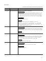
[DESIGN PRECAUTIONS]
DANGER
Incorrect operation of the touch switch(s) may lead to a serious accident if the GOT backlight is gone
out.
When the GOT backlight goes out, the POWER LED flickers (green/orange) and the display section
turns black and causes the monitor screen to appear blank, while the input of the touch switch(s)
remains active.
This may confuse an operator in thinking that the GOT is in "screensaver" mode, who then tries to
release the GOT from this mode by touching the display section, which may cause a touch switch to
operate.
Note that the following occurs on the GOT when the backlight goes out.
•The POWER LED flickers (green/orange) and the monitor screen appears blank
CAUTION
Do not bundle the control and communication cables with main-circuit, power or other wiring.
Run the above cables separately from such wiring and keep them a minimum of 100mm (3.94in.)
apart.Not doing so noise can cause a malfunction.
[MOUNTING PRECAUTIONS]
DANGER
Be sure to shut off all phases of the external power supply used by the system before mounting or
removing the GOT main unit to/from the panel.
Not doing so can cause the unit to fail or malfunction.
Be sure to shut off all phases of the external power supply used by the system before mounting or
removing the communication unit, option function board or multi-color display board onto/from the
GOT.
Not doing so can cause the unit to fail or malfunction.
When installing the multi-color display board, wear an earth band etc. to avoid the static
electricity.Not doing so can cause a unit corruption.
CAUTION
Use the GOT in the environment that satisfies the general specifications described in this manual.
Not doing so can cause an electric shock, fire, malfunction or product damage or deterioration.
When mounting the GOT to the control panel, tighten the mounting screws in the specified torque
range.
Undertightening can cause the GOT to drop, short circuit or malfunction.
Overtightening can cause a drop, short circuit or malfunction due to the damage of the screws or the
GOT.
A-2
[MOUNTING PRECAUTIONS]
CAUTION
When loading the communication unit to the GOT, fit it to the connection interface of the GOT and
tighten the mounting screws in the specified torque range.
Undertightening can cause the GOT to drop, short circuit or malfunction.
Overtightening can cause a drop, failure or malfunction due to the damage of the screws or unit.
When mounting the multi-color display board onto the GOT, tighten the mounting screws within the
specified torque range.
Loose tightening may cause the unit and/or GOT to malfunction due to poor contact.
Overtightening may damage the screws, unit and/or GOT; they might malfunction.
Push the option function board onto the corresponding connector until it clicks, so that it will be
secured firmly.
Push the multi-color display board onto the corresponding connector so that it will be secured firmly.
When inserting a CF card into the GOT, push it into the insertion slot until the CF card eject button
will pop out.
Failure to do so may cause a malfunction due to poor contact.
When inserting/removing a CF card into/from the GOT, turn the CF card access switch off in
advance.
Failure to do so may corrupt data within the CF card.
When removing a CF card from the GOT, make sure to support the CF card by hand, as it may pop
out.
Failure to do so may cause the CF card to drop from the GOT and break.
[WIRING PRECAUTIONS]
DANGER
Be sure to shut off all phases of the external power supply used by the system before wiring.
Failure to do so may result in an electric shock, product damage or malfunctions.
A-3
[WIRING PRECAUTIONS]
CAUTION
Always ground the FG terminal, LG terminal, and protective ground terminal of the GOT power to the
protective ground conductors dedicated to the GOT.
Not doing so may cause an electric shock or malfunction.
Terminal screws which are not to be used must be tightened always at torque 0.5 to 0.8 N·m.
Otherwise there will be a danger of short circuit against the solderless terminals.
Use applicable solderless terminals and tighten them with the specified torque.
If any solderless spade terminal is used, it may be disconnected when the terminal screw comes
loose, resulting in failure.
Correctly wire the GOT power supply section after confirming the rated voltage and terminal
arrangement of the product.
Not doing so can cause a fire or failure.
Tighten the terminal screws of the GOT power supply section in the specified torque range.
Undertightening can cause a short circuit or malfunction.
Overtightening can cause a short circuit or malfunction due to the damage of the screws or the GOT.
Exercise care to avoid foreign matter such as chips and wire offcuts entering the GOT. Not doing so
can cause a fire, failure or malfunction.
Plug the bus connection cable by inserting it into the connector of the connected unit until it "clicks".
After plugging, check that it has been inserted snugly.
Not doing so can cause a malfunction due to a contact fault.
Plug the communication cable into the connector of the connected unit and tighten the mounting and
terminal screws in the specified torque range.
Undertightening can cause a short circuit or malfunction.
Overtightening can cause a short circuit or malfunction due to the damage of the screws or unit.
[TEST OPERATION PRECAUTIONS]
DANGER
When testing the operation (e.g. turning bit devices ON/OFF or changing a current word device
value, a current or set timer/counter value, or a current buffer memory value), thoroughly read the
relevant manual to fully understand the operating procedures. When testing, never change the data
of the devices that control the operation essential for the system.
False output or malfunction can cause an accident.
A-4
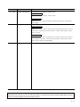
[STARTUP/MAINTENANCE PRECAUTIONS]
DANGER
When power is on, do not touch the terminals.
Doing so can cause an electric shock or malfunction.
Connect the battery correctly.
Do not discharge, disassemble, heat, short, solder or throw the battery into the fire.
Incorrect handling may cause the battery to generate heat, burst or take fire, resulting in injuries or
fires
Before starting cleaning or terminal screw retightening, always switch off the power externally in all
phases.
Not switching the power off in all phases can cause a unit failure or malfunction.
Undertightening can cause a short circuit or malfunction.
Overtightening can cause a short circuit or malfunction due to the damage of the screws or unit.
CAUTION
Do not disassemble or modify the unit.
Doing so can cause a failure, malfunction, injury or fire.
Do not touch the conductive and electronic parts of the unit directly.
Doing so can cause a unit malfunction or failure.
The cables connected to the unit must be run in ducts or clamped.
Not doing so can cause the unit or cable to be damaged due to the dangling, motion or accidental
pulling of the cables or can cause a malfunction due to a cable connection fault.
When unplugging the cable connected to the unit, do not hold and pull the cable portion.
Doing so can cause the unit or cable to be damaged or can cause a malfunction due to a cable
connection fault.
Do not drop the module or subject it to strong shock.
A module damage may result.
Do not drop or give an impact to the battery mounted to the unit.
Doing so may damage the battery, causing the battery fluid to leak inside the battery.
If the battery is dropped or given an impact, dispose of it without using.
Before touching the unit, always touch grounded metal, etc. to discharge static electricity from
human body, etc.
Not doing so can cause the unit to fail or malfunction.
[BACKLIGHT REPLACEMENT PRECAUTIONS]
DANGER
Be sure to shut off all phases of the external power supply of the GOT (and the controller in the case
of a bus topology) and remove the GOT from the control panel before replacing the backlight (when
using the GOT with the backlight replaceable by the user).
Not doing so can cause an electric shock.
Replacing a backlight without removing the GOT from the control panel can cause the backlight or
control panel to drop, resulting in an injury.
A-5
[BACKLIGHT REPLACEMENT PRECAUTIONS]
CAUTION
Wear gloves for the backlight replacement when using the GOT with the backlight replaceable by the
user.
Not doing so can cause an injury.
Before replacing a backlight, allow 5 minutes or more after turning off the GOT when using the GOT
with the backlight replaceable by the user.
Not doing so can cause a burn from heat of the backlight.
[DISPOSAL PRECAUTIONS]
CAUTION
When disposing of the product, handle it as industrial waste.
[TRANSPORTATION PRECAUTIONS]
CAUTION
When transporting lithium batteries, make sure to treat them based on the transport regulations.
(Refer to Appendix 3 for details of the regurated units.)
Make sure to transport the GOT main unit and/or relevant unit(s) in the manner they will not be
exposed to the impact exceeding the impact resistance described in the general specifications of this
manual, as they are precision devices.
Failure to do so may cause the unit to fail.
Check if the unit operates correctly after transportation.
A-6
REVISIONS
* The manual number is given on the bottom left of the back cover.
Print Date
* Manual Number
Revision
Mar., 2005
SH(NA)-080544ENG-A First edition
Oct., 2005
SH(NA)-080544ENG-B Compatible with GT Designer2 Version2.18U.
Partial corrections
Abbreviations and generic terms in this manual, Chapter1, Section 1.1.1, 1.1.2,
1.1.3, 2.1, 2.2.1, 2.2.2, 2.3.1, 2.4.2, 2.4.3, 2.4.4, 2.4.5, 2.5, 2.5.1, 2.5.3, 2.6.1,
2.7.1, 2.8.1, 2.9.2, 2.9.3, 2.9.4, 2.9.5, 3.1, 3.2.1, 3.2.2, 3.3, 3.3.1, 3.3.2, 3.3.3,
3.4.1, 3.8, 4.1, 4.2.1, 4.3, 4.3.1, 4.3.2, 4.4.1, 4.4.2, 4.4.7, 4.7.3, App.1, INDEX
Partial additions
Section 2.6, 2.7, 2.8, 3.4, 3.5.4
Additions
Section 2.2.3, 3.2.3, 3.2.4, 4.2.2, 4.4.6, Chapter 5, 6, 7, 8, 9, 10
Section 2.2.3
3.4.3
2.2.4, Section 5.1
3.4.2, Section 4.2.2
4.4.8, Section 5.2
Jan., 2006
2.10, Section 3.3.4
4.2.3, Section 4.4.6
3.8, Section 5.3
3.3.3, Section
4.4.7, Section 4.4.7
4.7
SH(NA)-080544ENG-C Compatible with GT Designer2 Version2.27D.
Partial corrections
About Manuals, Abbreviations and generic terms in this manual, How to read this
manual, Section 3.1, 3.4.2, 4.4.6, 5.4.12, 7.4.1, 8.4.11, 9.2.1, 9.4.8, 10.2.1, App1
Additions
Section 1.1.4, 3.5.7
Jun., 2006
SH(NA)-080544ENG-D Compatible with GT Designer2 Version2.32J.
Partial corrections
About Manuals, Abbreviations and generic terms in this manual, How to read this
manual, Section 1.1.1, 1.1.2, 2.3.1, 3.2.1, 3.3.2, 4.1, 5.1, 5.3, 6.1, 6.2.2, 6.4.1,
6.4.2, 7.1, 7.2.1, 7.2.4, 8.2.1, 8.4.2, 8.4.11, 10.2.1, 10.2.3, App1
Additions
Chapter 1, Section 2.1, 3.2.4, 8.2.3, 9.2.1
Nov., 2006
SH(NA)-080544ENG-E Compatible with GT Designer2 Version2.43V.
Partial corrections
Section 2.2.4, 3.1, 3.2.4, 3.3.2, 3.6, 3.8, 6.2.2, 7.2.3, 8.2.2
Partial additions
Section 3.3.1, 3.3.3, 3.4.1
(Continued to next page)
A-7
Print Date
* Manual Number
May, 2007
SH(NA)-080544ENG-F
Revision
Compatible with GT Designer2 Version 2.58L
Partial corrections
Section 1.1.1, 1.1.2, 2.1, 2.2.1, 2.5.1, 2.6.1, 2.7.1, 2.8.1, 2.9.3, 3.1, 3.2.1, 3.2.4,
3.3.1, 3.3.3, 3.3.4, 3.4.1, 3.4.2, 3.5.1 to 3.5.7, 3.6.1 to 3.6.7, 3.7.1, 4.2.1, 5.2.1,
5.3, 5.4.9 to 5.4.11, 7.1, 8.2.1, 8.4.11, 9.2.1, 9.4.8
Partial additions
Section 5.2.3, 5.4.1
Additions
Section 3.3.5, 3.8, 5.4.12, 14.10, Chapter 11
Section 3.8
Aug., 2007
3.9, Section 5.4.12
5.4.13, Section 5.4.13
5.4.14
SH(NA)-080544ENG-G Compatible with GT Designer2 Version 2.63R
Partial corrections
Section 3.2.1, 8.2.3, 8.3, 8.4.1, 8.4.6
Partial additions
Chapter 1, Section 1.1.1, 1.1.2, 1.1.4, 2.2.3, 3.2.2, 3.2.3, 3.2.4, 6.2.2, 6.2.3,
8.2.1, 8.4.4, 10.2.1, 10.2.2, 10.2.3, 10.4, 10.5, 11.2.1, App1
Additions
Section 11.5, Chapter 12
Section 11.5
Dec., 2007
11.6
SH(NA)-080544ENG-H Compatible with GT Designer2 Version 2.72A
Partial corrections
Section 1.1.3, 1.1.4, 3.2.1, 3.3.3, 10.2, 10.2.1, 11.3.1, 11.3.2, 11.4.1, 11.5.2,
11.5.3, 12.4
Partial additions
Section 1.1.1, 1.1.2, 2.1, 2.3.1, 3.2.4, 3.4.1, 11.1, 11.2.1, 11.2.3, 11.3.3
Additions
Section 11.3.4
Feb., 2008
SH(NA)-080544ENG-I
Compatible with GT Designer2 Version 2.77F
Partial corrections
Section 1.1.3, 2.2.3, 3.2.3, 7.2.3
Partial additions
Chapter 1, Section 1.1.1, 1.1.2, 1.1.4, 2.2.1, 3.1, 3.2.1, 6.2.1, 6.2.2, 7.1, 7.2.1,
7.2.2, 7.2.4, 7.4.1 to 7.4.9, 8.2, App1
Additions
Chapter 13
(Continued to next page)
A-8
Print Date
* Manual Number
Revision
Jun., 2008
SH(NA)-080544ENG-J
Compatible with GT Designer2 Version 2.82L
Partial corrections
Section 3.2.2, 3.7, 6.4.4, 7.2.1, 11.2.1, 11.3.3
Partial additions
Section 1.1.1, 1.1.2, 2.2.1, 3.2.4, 6.2.1, 6.3, 6.4.1, 6.4.2, 6.4.3, 11.2.3, 11.6,
13.2.1, App1
Oct., 2008
SH(NA)-080544ENG-K Compatible with GT Designer2 Version 2.90U.
Partial corrections
Section 1.1.3, 2.1, 2.3.1, 3.3.1, 4.4.1, 5.5, 6.3, 7.3, 8.3, 9.3, 10.3, 11.1, 11.3.1,
11.3.4, 11.4.1, 11.4.3, 11.6, 12.3, 13.1, 13.3.1, 13.5.1, 13.5.2, 13.6.1, 13.6.3,
13.7.1
13.7.3
Partial additions
Section 1.1.1, 1.1.2, 2.2.1, 3.2.1, 3.5.4, 4.1, 4.2.1, 4.3.1, 4.4.6, 5.1, 5.2.3, 5.3,
5.4.1, 5.4.10, 5.4.13, 6.2.1, 7.2.1, 8.2.1, 9.2.1, 10.2.1, 10.2.3, 11.2.1, 11.3.2,
12.2.3, 13.2.1, 13.2.2, 13.8, 13.9, App1
Japanese Manual Version SH-080541-N
This manual confers no industrial property rights or any rights of any other kind, nor does it confer any patent licenses.
Mitsubishi Electric Corporation cannot be held responsible for any problems involving industrial property rights which may
occur as a result of using the contents noted in this manual.
© 2005 MITSUBISHI ELECTRIC CORPORATION
A-9
INTRODUCTION
Thank you for choosing Mitsubishi Graphic Operation Terminal (Mitsubishi GOT).
Read this manual and make sure you understand the functions and performance of the GOT thoroughly
in advance to ensure correct use.
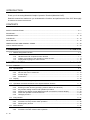
CONTENTS
SAFETY PRECAUTIONS .................................................................................................................................A - 1
REVISIONS.......................................................................................................................................................A - 7
INTRODUCTION.............................................................................................................................................A - 10
CONTENTS ....................................................................................................................................................A - 10
About Manuals ................................................................................................................................................A - 18
ABBREVIATIONS AND GENERIC TERMS....................................................................................................A - 20
How to read this manual .................................................................................................................................A - 24
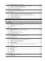
1. OVERVIEW
1.1
1 - 1 to 1 - 12
Before Using Each Function
1.1.1
1.1.2
1.1.3
1.1.4
1-2
Each function and related manuals ...................................................................................... 1 - 2
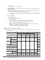
Hardware and OS’ required for each function ...................................................................... 1 - 4
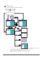
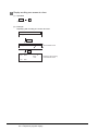
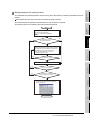
Outline of procedure to the operation of each function....................................................... 1 - 10
Displayable languages for each function ............................................................................ 1 - 12
2. SYSTEM MONITOR
2 - 1 to 2 - 56
2.1
Features
2-1
2.2
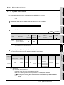
Specifications
2-6
2.2.1
2.2.2
2.2.3
2.2.4
2.3
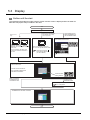
Display
2.3.1
2.4
2.6
A - 10
2 - 31
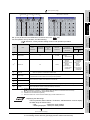
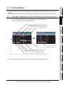
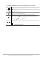
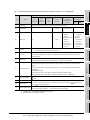
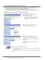
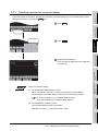
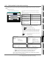
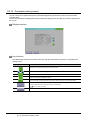
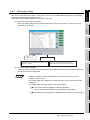
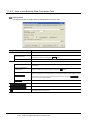
Information displayed on the Entry Monitor screen and key functions ............................... 2 - 31
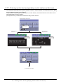
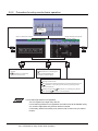
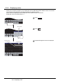
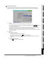
Procedure for entry monitor basic operation....................................................................... 2 - 34
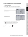
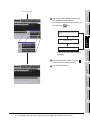
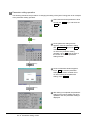
Deleting entry devices ........................................................................................................ 2 - 35
Batch Monitor
2.6.1
2.6.2
2 - 19
Functional change menu screen......................................................................................... 2 - 19
Entering monitor devices (specifying monitor stations and devices) .................................. 2 - 20
Key window setting columns and operation procedure ...................................................... 2 - 23
Switching the display format (DEC/HEX) and comment/no-comment display.................... 2 - 24
Quick test operation of monitor devices.............................................................................. 2 - 26
Changing screens............................................................................................................... 2 - 30
Entry Monitor
2.5.1
2.5.2
2.5.3
2 - 16
Outline until starting the system monitor............................................................................. 2 - 16
Operation Procedure Common to the System Monitor Screens
2.4.1
2.4.2
2.4.3
2.4.4
2.4.5
2.4.6
2.5
System configuration ............................................................................................................ 2 - 6
Devices that can be monitored ........................................................................................... 2 - 14
Access range ...................................................................................................................... 2 - 14
Precautions......................................................................................................................... 2 - 14
2 - 36
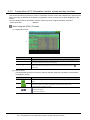
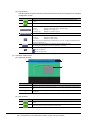
Information displayed on the Batch Monitor screen and key functions............................... 2 - 36
Procedure for batch monitor basic operation...................................................................... 2 - 40
2.7
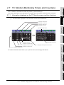
TC Monitor (Monitoring Timers and Counters)
2.7.1
2.7.2
2.7.3
2.8
2.9
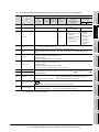
Information displayed on the TC Monitor screen and key functions ................................... 2 - 41
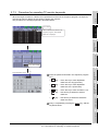
Procedure for TC monitor basic operation.......................................................................... 2 - 44
Procedure for canceling TC monitor keywords................................................................... 2 - 45
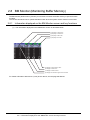
BM Monitor (Monitoring Buffer Memory)
2.8.1
2.8.2
2 - 46
Information displayed on the BM Monitor screen and key functions .................................. 2 - 46
Procedure for BM monitor basic operation ......................................................................... 2 - 48
Test Operation
2.9.1
2.9.2
2.9.3
2.9.4
2.9.5
2 - 41
2 - 49
Procedure for displaying the test menu screen and the setting key window screen .......... 2 - 49
Information displayed on the test menu screen and key functions ..................................... 2 - 50
Information and set items displayed on each setting key window screen .......................... 2 - 51
Test operation procedure ................................................................................................... 2 - 53
Test operation basic procedure .......................................................................................... 2 - 55
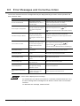
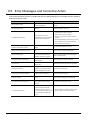
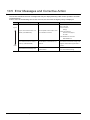
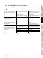
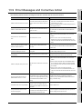
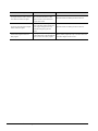
2.10 Error Messages and Corrective Action
3. LADDER MONITOR FUNCTION
2 - 56
3 - 1 to 3 - 74
3.1
Features
3-1
3.2
Specifications
3-4
3.2.1
3.2.2
3.2.3
3.2.4
3.3
Display
3.3.1
3.3.2
3.3.3
3.3.4
3.3.5
3.4
3.6
3.7
3.8
3 - 54
Device search ..................................................................................................................... 3 - 55
Contact point search........................................................................................................... 3 - 57
Coil search.......................................................................................................................... 3 - 59
Step search ........................................................................................................................ 3 - 61
Ladder end search.............................................................................................................. 3 - 62
Defect search ..................................................................................................................... 3 - 63
Touch search ...................................................................................................................... 3 - 67
Test Operation
3.7.1
3 - 45
Display switching of 16-bit (one-word)/32-bit (two-word) modules ..................................... 3 - 45
Display switching of decimal numbers/hexadecimal numbers............................................ 3 - 46
Switching comment/no-comment display ........................................................................... 3 - 47
Displaying 32 characters of comments............................................................................... 3 - 48
Displaying notes ................................................................................................................. 3 - 50
Displaying statements ........................................................................................................ 3 - 51
Language switching of the sequence program (MELSEC-Q/QnA ladder monitor)............. 3 - 52
Search Operation
3.6.1
3.6.2
3.6.3
3.6.4
3.6.5
3.6.6
3.6.7
3 - 37
Information and key functions displayed on the screen...................................................... 3 - 37
Hard copy output ................................................................................................................ 3 - 44
Switching the Display Format
3.5.1
3.5.2
3.5.3
3.5.4
3.5.5
3.5.6
3.5.7
3 - 15
Outline until the start........................................................................................................... 3 - 15
Setting and deleting media for saving ladder data ............................................................. 3 - 20
Display ................................................................................................................................ 3 - 21
Searching from the monitor screen .................................................................................... 3 - 31
Reading comment files from CF cards ............................................................................... 3 - 36
Operation Procedure Common
3.4.1
3.4.2
3.5
System configuration ............................................................................................................ 3 - 4
Devices and range that can be monitored ............................................................................ 3 - 9
Access range ...................................................................................................................... 3 - 11
Precautions......................................................................................................................... 3 - 11
3 - 69
Displaying the test menu screen ........................................................................................ 3 - 69
Local Device Monitor
3 - 70
A - 11
3.8.1
3.9
Operation procedure for local device monitor..................................................................... 3 - 70
Error Messages and Corrective Action
4. MELSEC-A LIST EDITOR
3 - 73
4 - 1 to 4 - 38
4.1
Features
4-1
4.2
Specifications
4-3
4.2.1
4.2.2
4.2.3
4.3
Display
4.3.1
4.3.2
4.4
4.6
4.7
4 - 28
Common operation ............................................................................................................. 4 - 28
Operation in write mode (W)............................................................................................... 4 - 29
Operation in read mode (R) ................................................................................................ 4 - 29
Operation in insert mode (I) ................................................................................................ 4 - 30
Operation in delete mode (D) ............................................................................................. 4 - 30
Operation in parameter mode (P) ....................................................................................... 4 - 31
Operation in other mode (O)............................................................................................... 4 - 32
Error Messages and Corrective Actions
4.7.1
4.7.2
4.7.3
4 - 21
Reading sequence programs.............................................................................................. 4 - 21
Changing (Overwriting) commands .................................................................................... 4 - 22
Adding (Inserting) commands............................................................................................. 4 - 23
Deleting commands ............................................................................................................ 4 - 24
Using the help function ....................................................................................................... 4 - 25
PLC memory all clear ......................................................................................................... 4 - 27
List of Operation Procedures
4.6.1
4.6.2
4.6.3
4.6.4
4.6.5
4.6.6
4.6.7
4 - 10
Key arrangement and a list of key functions....................................................................... 4 - 10
Display format of the display area ...................................................................................... 4 - 12
Switching valid keys (upper/lower functions) ...................................................................... 4 - 15
Selection and operation of modes ...................................................................................... 4 - 15
Command input procedures ............................................................................................... 4 - 16
Hard copy output ................................................................................................................ 4 - 19
Action if an incorrect key is input ........................................................................................ 4 - 19
List of functions................................................................................................................... 4 - 20
Basic Operation
4.5.1
4.5.2
4.5.3
4.5.4
4.5.5
4.5.6
4-6
Outline until the start............................................................................................................. 4 - 6
Operation of keyword input................................................................................................... 4 - 8
Operation Methods
4.4.1
4.4.2
4.4.3
4.4.4
4.4.5
4.4.6
4.4.7
4.4.8
4.5
System configuration ............................................................................................................ 4 - 3
Access range ........................................................................................................................ 4 - 4
Precautions........................................................................................................................... 4 - 5
4 - 33
Error messages and corrective actions in direct CPU connection...................................... 4 - 33
PLC CPU error messages and troubleshooting.................................................................. 4 - 36
Error using list editor function on the link system ............................................................... 4 - 37
5. MELSEC-FX LIST EDITOR
5 - 1 to 5 - 34
5.1
Features
5-1
5.2
Specifications
5-3
5.2.1
5.2.2
5.2.3
System configuration ............................................................................................................ 5 - 3
Access range ........................................................................................................................ 5 - 5
Precautions........................................................................................................................... 5 - 5
5.3
Display
5-6
5.4
Operation Procedures
5-9
5.4.1
A - 12
Key arrangement and a list of key functions......................................................................... 5 - 9
5.4.2
5.4.3
5.4.4
5.4.5
5.4.6
5.4.7
5.4.8
5.4.9
5.4.10
5.4.11
5.4.12
5.4.13
5.4.14
5.5
Selection and operation of modes ...................................................................................... 5 - 12
Sequence program display ................................................................................................. 5 - 13
Searching commands and devices..................................................................................... 5 - 15
Writing commands .............................................................................................................. 5 - 17
Changing operands, set values .......................................................................................... 5 - 20
Deleting commands ............................................................................................................ 5 - 21
Sequence program all clear................................................................................................ 5 - 22
PLC diagnostics.................................................................................................................. 5 - 23
Parameter setting ............................................................................................................... 5 - 25
Keywords ............................................................................................................................ 5 - 28
List monitor ......................................................................................................................... 5 - 30
Hard copy output ................................................................................................................ 5 - 32
Action for an incorrect key input ......................................................................................... 5 - 32
Error Messages and Corrective Actions
6. INTELLIGENT MODULE MONITOR
5 - 33
6 - 1 to 6 - 116
6.1
Features
6-1
6.2
Specifications
6-3
6.2.1
6.2.2
6.2.3
System configuration ............................................................................................................ 6 - 3
Access range ........................................................................................................................ 6 - 6
Precautions........................................................................................................................... 6 - 8
6.3
Display
6 - 11
6.4
Operation of Each Intelligent Module Monitor Screen
6 - 15
6.4.1
6.4.2
6.4.3
6.4.4
6.4.5
6.4.6
6.4.7
6.5
Composition of the system configuration screen and key functions ................................... 6 - 15
Setting method for other station monitoring........................................................................ 6 - 17
Composition of PC Information monitor screen and key functions .................................... 6 - 18
Composition of the unit detail info screen and key functions ............................................. 6 - 22
Composition of the intelligent module monitor screen and key functions ........................... 6 - 23
Specifying a module to monitor and selecting monitor menu ............................................. 6 - 24
Testing of the intelligent function module ........................................................................... 6 - 25
Intelligent Module Monitor Screens
6.5.1
6.5.2
6.5.3
6.5.4
6.5.5
6.5.6
6.5.7
6.5.8
6.5.9
6.5.10
6.5.11
6.5.12
6.5.13
6.5.14
6.5.15
6.5.16
6.5.17
6.5.18
6.5.19
6.5.20
6.5.21
6.5.22
6 - 27
A62DA-S1 module monitoring ............................................................................................ 6 - 27
A68AD module monitoring.................................................................................................. 6 - 28
A68ADN module monitoring ............................................................................................... 6 - 29
A68RD module monitoring ................................................................................................. 6 - 30
A84AD module monitoring.................................................................................................. 6 - 31
A616AD module monitoring................................................................................................ 6 - 33
A616TD module monitoring ................................................................................................ 6 - 35
A616DAV module monitoring ............................................................................................. 6 - 38
A616DAI module monitoring............................................................................................... 6 - 39
A61LS module monitoring .................................................................................................. 6 - 40
A62LS module monitoring .................................................................................................. 6 - 41
AD61 module monitoring .................................................................................................... 6 - 42
AD70 module monitoring .................................................................................................... 6 - 43
AD70D module monitoring ................................................................................................. 6 - 45
AD71 module monitoring .................................................................................................... 6 - 47
AD72/A1SD71 module monitoring...................................................................................... 6 - 50
AJ71PT32-S3 module monitoring....................................................................................... 6 - 53
A1SD61 module monitoring................................................................................................ 6 - 55
A1S64AD module monitoring ............................................................................................. 6 - 56
A1S62DA module monitoring ............................................................................................. 6 - 57
A1SD70 module monitoring................................................................................................ 6 - 58
A1S62RD module monitoring ............................................................................................. 6 - 59
A - 13
6.5.23
6.5.24
6.5.25
6.5.26
6.5.27
6.5.28
6.5.29
6.5.30
6.5.31
6.5.32
6.5.33
6.5.34
6.5.35
6.5.36
6.6
Operating I/O Module Monitor Screen
6.6.1
6.6.2
6.7
A1SJ71PT32-S3 module monitoring .................................................................................. 6 - 60
A1S63ADA module monitoring ........................................................................................... 6 - 61
AD75P/A1SD75P module monitoring ................................................................................. 6 - 62
AJ71ID1(ID2)-R4/A1SJ71ID1(ID2)-R4 module monitoring................................................. 6 - 68
A1S68DAV module monitoring ........................................................................................... 6 - 69
A1S68DAI module monitoring ............................................................................................ 6 - 70
A1S68AD module monitoring ............................................................................................. 6 - 71
A1S64TCTT(BW)/A1S64TCRT(BW)-S1 monitoring........................................................... 6 - 72
Q68ADV/Q68ADI/Q64AD module monitoring .................................................................... 6 - 74
Q62DA/Q64DA module monitoring..................................................................................... 6 - 75
QD62D/QD62E/QD62 module monitoring .......................................................................... 6 - 76
QD75P/QD75D module monitoring .................................................................................... 6 - 77
QD75M module monitoring................................................................................................. 6 - 87
QD75MH module monitoring ............................................................................................ 6 - 100
6 - 113
Specifying the module to be monitored ............................................................................ 6 - 113
Monitor screen configuration and key functions ............................................................... 6 - 114
Error Messages and Corrective Action
7. NETWORK MONITOR
6 - 115
7 - 1 to 7 - 30
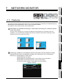
7.1
Features
7-1
7.2
Specifications
7-3
7.2.1
7.2.2
7.2.3
7.2.4
System configuration ............................................................................................................ 7 - 3
Network information that can be monitored .......................................................................... 7 - 5
Access range ........................................................................................................................ 7 - 7
Precautions........................................................................................................................... 7 - 7
7.3
Display
7.4
Operation Procedures
7.4.1
7.4.2
7.4.3
7.4.4
7.4.5
7.4.6
7.4.7
7.4.8
7.4.9
7.5
7-9
7 - 12
Line monitor ........................................................................................................................ 7 - 12
Detailed monitor.................................................................................................................. 7 - 15
Other station monitor .......................................................................................................... 7 - 23
Other station communication status monitor ...................................................................... 7 - 24
Other station data link status monitor ................................................................................. 7 - 25
Other station parameter status monitor .............................................................................. 7 - 26
Other station CPU operation status monitor ....................................................................... 7 - 27
Other station CPU RUN status monitor .............................................................................. 7 - 28
Other station loop status monitor........................................................................................ 7 - 29
Error Message and Corrective Action
8. Q MOTION MONITOR
7 - 30
8 - 1 to 8 - 26
8.1
Features
8-1
8.2
Specifications
8-3
8.2.1
8.2.2
8.2.3
System configuration ............................................................................................................ 8 - 3
Access range ........................................................................................................................ 8 - 5
Precautions........................................................................................................................... 8 - 5
8.3
Display
8-6
8.4
Operation Procedures
8-9
8.4.1
8.4.2
8.4.3
A - 14
System configuration screen layout...................................................................................... 8 - 9
Monitor Menu screen .......................................................................................................... 8 - 10
Present Value Monitor screen ............................................................................................ 8 - 11
8.4.4
8.4.5
8.4.6
8.4.7
8.4.8
8.4.9
8.4.10
8.4.11
8.5
SFC Error History screen ................................................................................................... 8 - 12
Error List screen ................................................................................................................. 8 - 13
Error List Designated-Axis screen ...................................................................................... 8 - 15
Positioning Monitor screen ................................................................................................. 8 - 17
Servo Monitor screen ......................................................................................................... 8 - 19
Present Value History Monitor screen ................................................................................ 8 - 20
Parameter setting screen ................................................................................................... 8 - 22
Hard copy output ................................................................................................................ 8 - 25
Error Messages and Corrective Action
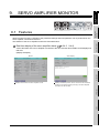
9. SERVO AMPLIFIER MONITOR
8 - 26
9 - 1 to 9 - 44
9.1
Features
9-1
9.2
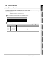
Specifications
9-3
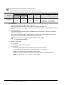
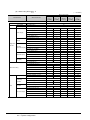
9.2.1
9.2.2
9.2.3
System configuration ............................................................................................................ 9 - 3
Access range ...................................................................................................................... 9 - 11
Precautions......................................................................................................................... 9 - 11
9.3
Display
9 - 12
9.4
Operations of Servo Amplifier Monitor Screens
9 - 15
9.4.1
9.4.2
9.4.3
9.4.4
9.4.5
9.4.6
9.4.7
9.4.8
9.5
Servo amplifier monitor....................................................................................................... 9 - 15
Setup .................................................................................................................................. 9 - 16
Monitor functions ................................................................................................................ 9 - 17
Alarm function..................................................................................................................... 9 - 19
Diagnostics function ........................................................................................................... 9 - 22
Parameter setting ............................................................................................................... 9 - 29
Test operations ................................................................................................................... 9 - 35
Hard copy output ................................................................................................................ 9 - 43
Error Messages and Corrective Action
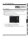
10. CNC MONITOR FUNCTIONS
9 - 44
10 - 1 to 10 - 10
10.1
Features
10 - 1
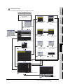
10.2
Specifications
10 - 2
10.2.1
10.2.2
10.2.3
System configuration .......................................................................................................... 10 - 2
Access range ...................................................................................................................... 10 - 5
Precautions......................................................................................................................... 10 - 5
10.3
Display
10 - 6
10.4
Operation Procedures
10 - 8
10.5
Error Messages and Corrective Action
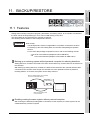
11. BACKUP/RESTORE
10 - 10
11 - 1 to 11 - 36
11.1
Features
11 - 1
11.2
Specifications
11 - 3
11.2.1
11.2.2
11.2.3
11.3
System configuration .......................................................................................................... 11 - 3
Access range ...................................................................................................................... 11 - 9
Precautions......................................................................................................................... 11 - 9
Display Operation
11.3.1
11.3.2
11.3.3
11.3.4
11 - 11
Outline before starting ...................................................................................................... 11 - 11
Setting storage location for backup data .......................................................................... 11 - 13
Security and password ..................................................................................................... 11 - 14
Trigger backup.................................................................................................................. 11 - 19
A - 15
11.4
Operation Procedures
11.4.1
11.4.2
11.4.3
11.4.4
11.5
11.6
Main menu ........................................................................................................................ 11 - 26
Progress screen (backup)................................................................................................. 11 - 27
Data list (restoration) ........................................................................................................ 11 - 28
Progress screen (restoration) ........................................................................................... 11 - 29
Backup Data Conversion Tool
11.5.1
11.5.2
11.5.3
11 - 26
11 - 30
Operating environment ..................................................................................................... 11 - 30
How to install and start Backup Data Conversion Tool..................................................... 11 - 31
How to use Backup Data Conversion Tool ....................................................................... 11 - 32
Errors and Corrective Actions
12. CNC DATA I/O
11 - 35
12 - 1 to 12 - 10
12.1
Features
12 - 1
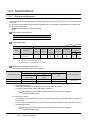
12.2
Specifications
12 - 2
12.2.1
12.2.2
12.2.3
System configuration .......................................................................................................... 12 - 2
Access range ...................................................................................................................... 12 - 3
Precautions......................................................................................................................... 12 - 3
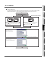
12.3
Display
12 - 5
12.4
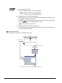
Operation Procedures
12 - 7
12.5
Error Messages and Corrective Actions
12 - 9
13. SFC MONITOR
13 - 1 to 13 - 42
13.1
Features
13 - 1
13.2
Specifications
13 - 4
13.2.1
13.2.2
13.2.3
13.2.4
13.3
Display Operation
13.3.1
13.3.2
13.3.3
13.4
13.6
13.7
A - 16
13 - 23
Displayed contents ........................................................................................................... 13 - 23
Key functions .................................................................................................................... 13 - 24
Menus ............................................................................................................................... 13 - 24
How to Operate SFC Diagram Monitor Screen
13.7.1
13.7.2
13.7.3
13 - 17
Displayed contents ........................................................................................................... 13 - 17
Key functions .................................................................................................................... 13 - 20
How to Operate Block List Screen
13.6.1
13.6.2
13.6.3
13 - 15
Switching languages of SFC programs ............................................................................ 13 - 15
Setting display mode of SFC programs ............................................................................ 13 - 15
Setting zoom comment display mode............................................................................... 13 - 15
Switching display formats between decimal and hexadecimal numbers .......................... 13 - 15
Setting automatic scroll mode........................................................................................... 13 - 16
How to Operate PLC Read Screen
13.5.1
13.5.2
13 - 9
Outline before starting ........................................................................................................ 13 - 9
Setting SFC data storage location .................................................................................... 13 - 12
Reading comment files from CF card ............................................................................... 13 - 13
Setting Display Format
13.4.1
13.4.2
13.4.3
13.4.4
13.4.5
13.5
System configuration .......................................................................................................... 13 - 4
Devices and range that can be monitored .......................................................................... 13 - 7
Access range ...................................................................................................................... 13 - 8
Precautions......................................................................................................................... 13 - 8
13 - 25
Displayed contents ........................................................................................................... 13 - 25
Key functions .................................................................................................................... 13 - 28
Menus ............................................................................................................................... 13 - 29
13.8
Test Operation
13 - 38
13.9
Error Messages and Corrective Action
13 - 41
APPENDICES
App - 1 to App - 34
Appendix1
List of Functions Added by GT Designer2 Version Upgrade (For GOT1000 Series) ...... App - 1
Appendix.1.1GT16, GT15, GT SoftGOT1000 and GT11.....................................................................App - 1
Appendix.1.2For GT10.......................................................................................................................App - 31
INDEX
Index - 1 to Index - 8
A - 17
About Manuals
The following manuals are also related to this product.
If necessary, order them by quoting the details in the tables below.
The manual in PDF-format is included in the GT Works2 and GT Designer2 products.
Related Manuals
Manual Number
Manual Name
(Model Code)
GT16 User's Manual
-Describes the GT16 hardware-relevant contents, including the specifications, part names, mounting, power
supply wiring, external dimensions, and option devices.
SH-080778ENG
(1D7M88)
-Describes the GT16 functions, including the utility.
(Sold separately)
GT15 User's Manual
-Describes the GT15 hardware-relevant contents, including the specifications, part names, mounting, power
supply wiring, external dimensions, and option devices.
SH-080528ENG
(1D7M23)
-Describes the GT15 functions, including the utility.
(Sold separately)
GT11 User's Manual
-Describes the GT11 hardware-relevant contents, including the specifications, part names, mounting, power
supply wiring, external dimensions, and option devices.
JY997D17501A
(09R815)
-Describes the GT11 functions, including the utility.
(Sold separately)
Handy GOT User's Manual
-Describes the Handy GOT hardware-relevant contents, including the system configurations, specifications, part
names, mounting, power supply wiring, external dimensions, and option devices.
JY997D20101B
(09R817)
-Describes the Handy GOT functions, including the utility, and how to make cables.
(Sold separately)
GT10 User's Manual
-Describes the GT10 hardware-relevant contents, including the specifications, part names, mounting, power
supply wiring, external dimensions, and option devices.
JY997D24701
(09R819)
-Describes the GT10 functions, including the utility.
(Sold separately)
GT SoftGOT1000 Version2 Operating Manual
SH-080602ENG
Describes the screen configuration, functions and using method of GT SoftGOT1000.
(Sold separately)
(1D7M48)
GT Designer2 Version2 Basic Operation/Data Transfer Manual (For GOT1000 Series)
Describes methods of the GT Designer2 installation operation, basic operation for drawing and transmitting data
SH-080529ENG
(1D7M24)
to GOT1000 series
(Sold separately)
GT Designer2 Version2 Screen Design Manual (For GOT1000 Series) (1/3, 2/3, 3/3)
SH-080530ENG
(1D7M25)
Describes specifications and settings of each object function applicable to GOT1000 series.
(Sold separately)
GOT1000 Series Connection Manual (1/3, 2/3, 3/3)
Describes system configurations of the connection method applicable to GOT1000 series and cable creation
(Sold separately)
SH-080532ENG
(1D7M26)
(Continued to next page)
A - 18
Manual Number
Manual Name
(Model Code)
GOT1000 Series Gateway Functions Manual
SH-080545ENG
Describes specifications, system comfigurations and setting method of the gateway function.
(Sold separately)
GOT1000 Series MES Interface Function Manual
Describes the specifications, system configurations, and setting method of GT MES interface function.
(Sold separately)
(1D7M33)
SH-080654ENG
(1D7M63)
A - 19
ABBREVIATIONS AND GENERIC TERMS
Abbreviations and generic terms used in this manual are as follows:
GOT
Abbreviations and generic terms
Description
GT SoftGOT1000
Abbreviation of GT SoftGOT1000
GT1695
GT1695M-X
Abbreviation of GT1695M-XTBA, GT1695M-XTBD
GT1685
GT1685M-S
Abbreviation of GT1685M-STBA, GT1685M-STBD
GT16
GT1595
, GT16
Abbreviation of GT1695, GT1685
GT1595-X
Abbreviation of GT1595-XTBA, GT1595-XTBD
GT1585V-S
Abbreviation of GT1585V-STBA, GT1585V-STBD
GT1585-S
Abbreviation of GT1585-STBA, GT1585-STBD
GT1575V-S
Abbreviation of GT1575V-STBA, GT1575V-STBD
GT1575-S
Abbreviation of GT1575-STBA, GT1575-STBD
GT1575-V
Abbreviation of GT1575-VTBA, GT1575-VTBD
GT1575-VN
Abbreviation of GT1575-VNBA, GT1575-VNBD
GT1585
GT157
GT1572-VN
Abbreviation of GT1572-VNBA, GT1572-VNBD
GT1565-V
Abbreviation of GT1565-VTBA, GT1565-VTBD
GT1562-VN
Abbreviation of GT1562-VNBA, GT1562-VNBD
GT1555-V
Abbreviation of GT1555-VTBD
GT1555-Q
Abbreviation of GT1555-QTBD, GT1555-QSBD
GT1550-Q
Abbreviation of GT1550-QLBD
GT156
GOT1000 Series
GT155
GT15
, GT15
GT1155-Q
GT115
Abbreviation of GT1595, GT1585, GT157 , GT156 , GT155
Abbreviation of GT1155-QTBDQ, GT1155-QSBDQ, GT1155-QTBDA, GT1155-QSBDA,
GT1155-QTBD, GT1155-QSBD
GT1150-Q
Abbreviation of GT1150-QLBDQ, GT1150-QLBDA, GT1150-QLBD
Handy
GT1155HS-Q
Abbreviation of GT1155HS-QSBD
GOT
GT1150HS-Q
Abbreviation of GT1150HS-QLBD
GT11
, GT11
Abbreviation of GT115 , GT11 Handy GOT
GT1055-Q
Abbreviation of GT1055-QSBD
GT1050-Q
Abbreviation of GT1050-QBBD
GT105
GT1030
Abbreviation of GT1030-LBD, GT1030-LBD2, GT1030-LBDW, GT1030-LBDW2
Abbreviation of GT1020-LBD, GT1020-LBD2, GT1020-LBL, GT1020-LBDW,
GT1020
GT10
GT1020-LBDW2, GT1020-LBLW
, GT10
Abbreviation of GT105 , GT1030, GT1020
GOT900 Series
Abbreviation of GOT-A900 series, GOT-F900 series
GOT800 Series
Abbreviation of GOT-800 series
A - 20
Communication unit
Abbreviations and generic terms
Description
GT15-QBUS,
GT15-QBUS2,
GT15-ABUS,
GT15-ABUS2,
GT15-75QBUSL,
GT15-75QBUS2L,
GT15-75ABUSL,
GT15-75ABUS2L
Serial communication unit
GT15-RS2-9P,
GT15-RS4-9S,
GT15-RS4-TE
RS-422 conversion unit
GT15-RS2T4-9P,
GT15-RS2T4-25P
Ethernet communication unit
GT15-J71E71-100
MELSECNET/H communication unit
GT15-J71LP23-25,
GT15-J71BR13
MELSECNET/10 communication unit
GT15-75J71LP23-Z*1,
GT15-75J71BR13-Z*2
Bus connection unit
CC-Link IE controller network communication
unit
GT15-J71GP23-SX
CC-Link communication unit
GT15-J61BT13,
Interface converter unit
GT15-75IF900
*1
A9GT-QJ71LP23 + GT15-75IF900 set
*2
A9GT-QJ71BR13 + GT15-75IF900 set
*3
A8GT-J61BT13 + GT15-75IF900 set
GT15-75J61BT13-Z*3
Option unit
Abbreviations and generic terms
Printer unit
Description
GT15-PRN
Video input unit
GT16M-V4,
GT15V-75V4
RGB input unit
GT16M-R2,
GT15V-75R1
Video/RGB input unit
GT16M-V4R1,
GT15V-75V4R1
RGB output unit
GT16M-ROUT,
GT15V-75ROUT
Video/RGB unit
Multimedia unit
GT16M-MMR
CF card unit
GT15-CFCD
CF card extension unit
*1
GT15-CFEX-C08SET
External I/O unit
GT15-DIO,
Sound output unit
GT15-SOUT
*1
GT15-DIOR
GT15-CFEX + GT15-CFEXIF + GT15-C08CF set.
A - 21
Option
Abbreviations and generic terms
Memory card
CF card
Memory card adaptor
Option function board
Battery
Protective Sheet
Description
GT05-MEM-16MC,
GT05-MEM-32MC,
GT05-MEM-64MC,
GT05-MEM-128MC,
GT05-MEM-256MC
GT05-MEM-ADPC
GT16-MESB,
GT15-FNB,
GT15-QFNB,
GT15-QFNB16M,
GT15-QFNB32M,
GT15-QFNB48M,
GT15-MESB48M,
GT11-50FNB
GT16-90PSGW,
GT15-BAT,
GT11-50BAT
GT16-90PSCB,
GT16-90PSGB,
GT16-90PSCW,
GT16-80PSCB,
GT16-80PSGB,
GT16-80PSCW,
GT16-80PSGW,
GT15-90PSCB,
GT15-90PSGB,
GT15-90PSCW,
GT15-90PSGW,
GT15-80PSCB,
GT15-80PSGB,
GT15-80PSCW,
GT15-80PSGW,
GT15-70PSCB,
GT15-70PSGB,
GT15-70PSCW,
GT15-70PSGW,
GT15-60PSCB,
GT15-60PSGB,
GT15-60PSCW,
GT15-60PSGW,
GT15-50PSCB,
GT15-50PSGB,
GT15-50PSCW,
GT15-50PSGW,
GT11-50PSCB,
GT11-50PSGB,
GT11-50PSCW,
GT11-50PSGW,
GT10-50PSCB,
GT10-50PSGB,
GT10-50PSCW,
GT10-50PSGW,
GT10-30PSCB,
GT10-30PSGB,
GT10-30PSCW,
GT10-30PSGW,
GT10-20PSCB,
GT10-20PSGB,
GT10-20PSCW,
GT10-20PSGW
GT05-90PCO,
GT05-80PCO,
GT05-70PCO,
GT05-60PCO,
GT16-UCOV,
GT15-UCOV,
GT11-50UCOV
GT15-90STAND,
GT15-80STAND,
GT15-70STAND,
GT15-70ATT-98,
GT15-70ATT-87,
GT15-60ATT-97,
GT15-60ATT-96,
GT15-60ATT-87,
GT15-60ATT-77,
GT15-50ATT-95W,
GT15-50ATT-85
GT16-90XLTT,
GT16-80SLTT,
GT15-90XLTT,
GT15-80SLTT,
GT15-70SLTT,
GT15-70VLTT,
GT15-70VLTN,
GT15-60VLTT,
GT11H-50PSC,
Protective cover for oil
USB environmental protection cover
Stand
GT05-50PCO
A9GT-50STAND,
GT05-50STAND
Attachment
Backlight
GT15-60VLTN
Multi-color display board
GT15-XHNB,
Connector conversion box
GT11H-CNB-37S
Emergency stop sw guard cover
GT11H-50ESCOV
Memory loader
GT10-LDR
Memory board
GT10-50FMB
GT15-VHNB
Software
Abbreviations and generic terms
GT Works2 Version
Description
SW D5C-GTWK2-E, SW D5C-GTWK2-EV
GT Designer2 Version
SW D5C-GTD2-E, SW D5C-GTD2-EV
GT Designer2
Abbreviation of screen drawing software GT Designer2 for GOT1000/GOT900 series
GT Converter2
Abbreviation of data conversion software GT Converter2 for GOT1000/GOT900 series
GT Simulator2
Abbreviation of screen simulator GT Simulator 2 for GOT1000 / GOT900 series
GT SoftGOT1000
Abbreviation of monitoring software GT SoftGOT1000
GT SoftGOT2
Abbreviation of monitoring software GT SoftGOT2
GX Developer
Abbreviation of SW D5C-GPPW-E(-EV)/SW D5F-GPPW-E type software package
GX Simulator
Abbreviation of SW D5C-LLT-E(-EV) type ladder logic test tool function software packages
(SW5D5C-LLT (-EV) or later versions)
Document Converter
Abbreviation of document data conversion software Document Converter for GOT1000 series
PX Developer
Abbreviation of SW D5C-FBDQ-E type FBD software package for process control
A - 22
License key (for GT SoftGOT1000)
Abbreviations and generic terms
License
Description
GT15-SGTKEY-U, GT15-SGTKEY-P
License key (for GT SoftGOT2)
Abbreviations and generic terms
Description
License key
A9GTSOFT-LKEY-P (For DOS/V PC)
License key FD
SW5D5F-SGLKEY-J (For PC CPU module)
Others
Abbreviations and generic terms
Description
OMRON PLC
Abbreviation of PLC manufactured by OMRON Corporation
KEYENCE PLC
Abbreviation of PLC manufactured by KEYENCE CORPORATION
KOYO EI PLC
Abbreviation of PLC manufactured by KOYO ELECTRONICS INDUSTRIES CO., LTD.
SHARP PLC
Abbreviation of PLC manufactured by Sharp Corporation
JTEKT PLC
Abbreviation of PLC manufactured by JTEKT Corporation
TOSHIBA PLC
Abbreviation of PLC manufactured by TOSHIBA CORPORATION
TOSHIBA MACHINE PLC
Abbreviation of PLC manufactured by TOSHIBA MACHINE CO., LTD.
HITACHI IES PLC
Abbreviation of PLC manufactured by Hitachi Industrial Equipment Systems Co., Ltd.
HITACHI PLC
Abbreviation of PLC manufactured by Hitachi, Ltd.
FUJI FA PLC
Abbreviation of PLC manufactured by Fuji Electric FA Components & Systems Co., Ltd.
MATSUSHITA PLC
Abbreviation of PLC manufactured by Matsushita Electric Works, Ltd.
YASKAWA PLC
Abbreviation of PLC manufactured by YASKAWA Electric Corporation
YOKOGAWA PLC
Abbreviation of PLC manufactured by Yokogawa Electric Corporation
ALLEN-BRADLEY PLC
Abbreviation of Allen-Bradley PLC manufactured by Rockwell Automation, Inc.
GE FANUC PLC
Abbreviation of PLC manufactured by GE Fanuc Automation Corporation
LS IS PLC
Abbreviation of PLC manufactured by LS Industrial Systems Co., Ltd.
SCHNEIDER PLC
Abbreviation of PLC manufactured by Schneider Electric SA
SIEMENS PLC
Abbreviation of PLC manufactured by Siemens AG
OMRON temperature
controller
SHINKO indicating
controller
CHINO controller
Temperature
controller
FUJI SYS temperature
controller
YAMATAKE temperature
controller
YOKOGAWA temperature
controller
RKC temperature
controller
PC CPU module
Abbreviation of temperature controller manufactured by OMRON Corporation
Abbreviation of temperature controller manufactured by Shinko Technos Co., Ltd.
Abbreviation of temperature controller manufactured by CHINO CORPORATION
Abbreviation of temperature controller manufactured by Fuji Electric Systems Co., Ltd.
Abbreviation of temperature controller manufactured by Yamatake Corporation
Abbreviation of temperature controller manufactured by Yokogawa Electric Corporation
Abbreviation of temperature controller manufactured by RKC INSTRUMENT INC.
Abbreviation of PC CPU Unit manufactured by CONTEC CO., LTD
GOT (server)
Abbreviation of GOTs that use the server function
GOT (client)
Abbreviation of GOTs that use the client function
Windows
font
Intelligent function module
MODBUS
/TCP
Abbreviation of TrueType font and OpenType font available for Windows
(Differs from the True Type fonts settable with GT Designer2)
Indicates the modules other than the PLC CPU, power supply module and I/O module that are
mounted to the base unit.
Generic term for the protocol designed to use MODBUS
protocol messages on a TCP/IP
network.
A - 23
How to read this manual
1 Functions
This manual describes functions available for GT Designer2 Version2.90U.
For the added functions by the product version upgrade, refer to the list of functions added by GT
Designer2 version upgrade in Appendices.
2 Symbols
Following symbols are used in this manual.
Refers to the information
required.
Remark
Refers to the supplementary
explanations for reference.
....
Indicates the operation steps.
Menu and items are differentiated with
parentheses.
[
] :Refers to an item displayed on
the computer screen or the GOT
screen.
:Refers to a button displayed on
the computer screen or the GOT
screen, or a key of the computer
keyboard.
Show the items including detailed explanation
(manual and the chapter, section, item).
A - 24
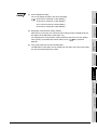
(1) Precautions for using each function
Some functions are not available depending on the GOT used, target CPU or
connection form.
For option function boards, functions available on each GOT, and restrictions on
each target CPU and connection form, see the appropriate chapter.
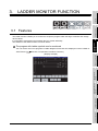
SYSTEM MONITOR
3
4
5
MELSEC-FX LIST
EDITOR
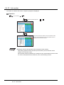
(2) Display examples in this manual
In this manual, with a few special exceptions, explanations are given primarily
using the GTI575-V screens.
2
LADDER MONITOR
FUNCTION
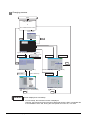
This manual describes the following functions available on a GOT system in which the standard monitor OS,
an Extended function OS, an Option OS, and the Communication driver are installed.
• System monitor
• Ladder monitor
• A list editor
• FX list editor
• Intelligent module monitor
• Network monitor
• Q motion monitor
• Servo amplifer monitor
• CNC monitor
• Backup/restore
• CNC data I/O
• SFC monitor
The monitor functions explained herein are intended to troubleshoot the PLC system and to streamline
maintenance operations.
OVERVIEW
1
OVERVIEW
MELSEC-A LIST EDITOR
1.
INTELLIGENT MODULE
MONITOR
6
NETWORK MONITOR
7
Q MOTION MONITOR
8
1-1
1.1 Before Using Each Function
1.1.1
Each function and related manuals
The difference between the extended and option functions of the GOT is shown below.
• Extended functions : Functions available by installing an Extended function OS.
• Option functions : Functions available by connecting an option function board (including a board with
add-on memory).
Many of the option functions require an Option OS to be installed.
For a description of each function, see the appropriate manual listed below.
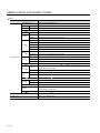
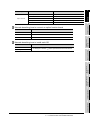
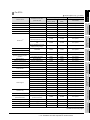
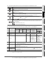
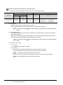
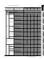
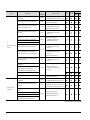
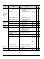
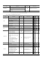
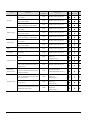
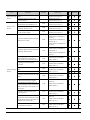
1 Manuals describing functions and how to set them
Category
Function name
Reference
Bar code
RFID
System monitor
GT Designer 2 Version
Screen Design Manual
Chapter 2
Stroke font
Video display
RGB display
GT Designer2 Version
Screen Design Manual
Remote personal computer operation
Multimedia
Backup/restore
Chapter11
CNC data I/O
Chapter12
Operator authentication
Sound output
External I/O/operation panel
GT Designer2 Version
Screen Design Manual
Device data transfer
Maintenance timing setting
GT15 User’s Manual
Multi-channel
Extended functions
KANJI regions
Operation log
Document display
Kana-kanji conversion*1
Kana-kanji conversion (enhanced version)
GT Designer 2 Version
Screen Design Manual
Historical Trend Graph
Logging
Recipe
Advanced Recipe
Object Script
Ladder monitor
Chapter 3
A list editor
Chapter 4
FX list editor
Chapter 5
Intelligent module monitor
Chapter 6
Network monitor
Chapter 7
Q motion monitor
Chapter 8
(Continued to next page)
1-2
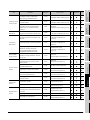
1.1 Before Using Each Function
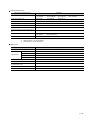
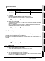
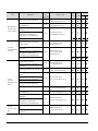
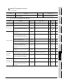
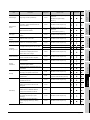
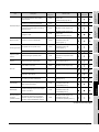
1.1.1 Each function and related manuals
Function name
Servo amplifer monitor
Option functions
1
Reference
Chapter 9
CNC monitor
Chapter 10
SFC monitor
Chapter 13
Gateway
GOT1000 Series Gateway Functions Manual
MES interface
GOT1000 Series MES Interface Function Manual
OVERVIEW
Category
2
Reference manual
GT16
GT16 User's Manual
GT15
GT15 User's Manual
GT11
GT11 User's Manual
3
LADDER MONITOR
FUNCTION
GOT
SYSTEM MONITOR
2 Manuals describing how to connect an option function board
3 Manuals describing how to install each OS
OS
Reference manual
Extended function OS
Basic Operation/Data Transfer Manual
4
MELSEC-A LIST EDITOR
GT Designer 2 Version
MELSEC-FX LIST
EDITOR
5
INTELLIGENT MODULE
MONITOR
6
NETWORK MONITOR
7
8
Q MOTION MONITOR
Option OS
1.1 Before Using Each Function
1.1.1 Each function and related manuals
1-3
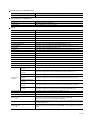
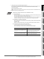
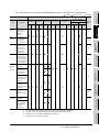
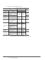
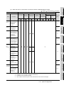
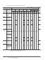
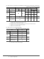
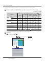
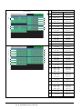
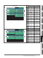
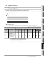
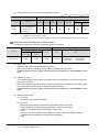
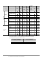
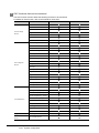
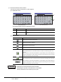
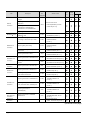
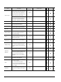
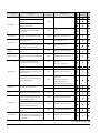
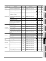
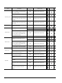
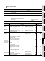
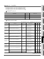
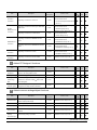
1.1.2
Hardware and OS’ required for each function
To use each function, extended function OS, or option OS and option function board is required.
For installing the extended function OS or option OS on the GOT, make sure that the user area of the
specified drive has enough free space for the OS memory space shown on the next page.
For details of data transfer, refer to the following.
GT Designer 2 Basic Operation/Data Transfer Manual
Subsection 8.1.2 Drive capacity required for data transfer
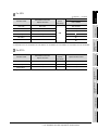
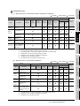
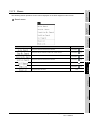
The following shows the option function boards applicable to each GOT.
GOT
Option function board
GT16
GT16-MESB
GT15
GT15-FNB, GT15-QFNB, GT15-QFNB16M, GT15-QFNB32M, GT15-QFNB48M, GT15-MESB48M
GT11
GT11-50FNB
GT10
Not required
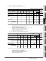
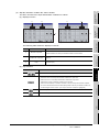
An option function board (GT15-FNB or GT11-50FNB) is built in the following GOTs.
GOT
GT15*1
Model
Description
All models
GT1155-QTBDQ, GT1155-QTBDA,
Function version D or later
GT1155-QSBDQ, GT1155-QSBDA,
GT1150-QLBDQ, GT1150-QLBDA
GT11
GT1155-QTBD
Hardware Version A or later
GT1155HS-QSBD, GT1150HS-QLBD
Hardware Version B or later
GT1155-QSBD, GT1150-QLBD
Hardware Version C or later
*1 For using an option function board built in the GOT, the latest standard monitor OS must be installed on the GOT.
For OS versions, refer to the following.
Appendix1 List of Functions Added by GT Designer2 Version Upgrade (For GOT1000
Series)
Option functions operated with the GT15-FNB or GT11-50FNB can be used without installing an additional
option function board.
For using functions operated with the GT16-MESB, GT15-QFNB( M), or GT15-MESB48M, and for adding
more memory to the GT15, install an applicable option function board.
An additional option function board can be installed on the GOT with a built-in option function board. (An
option function board inapplicable to the GOT cannot be used. (An option function board for the GT11 cannot
be installed on the GT15.))
For how to check function versions and hardware versions, refer to the following manuals.
GT15 User's Manual
GT11 User's Manual
Handy GOT User's Manual
1-4
1.1 Before Using Each Function
1.1.2 Hardware and OS’ required for each function
1
1 For GT16
Built-in flash
User memory
memory (ROM)
(RAM)
Option function board
GT16-MESB
Bar code
Bar code
84KB
84KB
Not required
RFID
RFID
166KB
166KB
Not required
System monitor
System monitor
746KB
746KB
Not required
Report
Report
150KB
235KB
Not required
Printer
Printer
522KB
1104KB
Not required
Stroke Font Support Data
400 KB
400 KB
Not required
Stroke Standard Font(JPN)
2160KB
2160KB
Not required
3175KB
3175KB
Not required
1474KB
1474KB
Not required
2016KB
2016KB
Not required
Video/RGB
292KB
474KB
Not required
Multimedia
Multimedia
292KB
1074KB
Not required
Remote personal computer
Video/RGB
292KB
474KB
Not required
operation
PC Remote Operation
50KB
84KB
Not required
Stroke Standard
Stroke font*2
Font(JPN)(supporting Hangul)
Stroke Standard Font(China
GB)
Stroke Standard Font(China
GB)(supporting Hangul)
2
3
4
MELSEC-A LIST EDITOR
Video display
RGB display
Backup/Restore
420KB
766KB
Not required
Operator authentication
460KB
730KB
Not required
Sound Output
Sound Output
100KB
200KB
Not required
External I/O / Operation Panel
External I/O / Operation Panel
70KB
100KB
Not required
CNC Data I/O
210KB
383KB
Not required
GOT Platform Library
77KB
200KB
Not required
Device data transfer
Device Data Transfer
50KB
100KB
Not required
Maintenance timing setting
Not required
-
-
Not required
Multi-channel
Not required
-
-
Not required
Standard Font (China GB)
1280KB
1280KB
Not required
Standard Font (China Big5)
1920KB
1920KB
Not required
Standard Font (Japanese)
1280KB
1280KB
Not required
Stroke Font (JPN)
1037KB
1037KB
Not required
Stroke Font (China GB5)
1248KB
1248KB
Not required
Stroke Font (China Big5)
1680KB
1680KB
Not required
Operation Log
384KB
1221KB
Not required
5
MELSEC-FX LIST
EDITOR
Backup/restore
Operator Authentication
CNC data I/O
INTELLIGENT MODULE
MONITOR
6
KANJI regions
7
Device name converter
400KB
800KB
Not required
Document Display
150KB
3072KB
Not required
242KB
1274KB
Not required
-
Not required
Kana-kanji conversion
KANA KANJI(JPN)
(enhanced version)
(Enhanced Version)
Historical Trend Graph
Not required
-
Logging
Logging
380KB
710KB
Not required
Recipe
Recipe
70KB
100KB
Not required
Advanced Recipe
Advanced Recipe
310KB
1187KB
Not required
NETWORK MONITOR
Operation log
Document display
8
(Continued to next page)
1.1 Before Using Each Function
1.1.2 Hardware and OS’ required for each function
OVERVIEW
option OS name
OS memory space (user
SYSTEM MONITOR
Extended function OS /
LADDER MONITOR
FUNCTION
Function name
: Unusable
1-5
Q MOTION MONITOR
: Required (Either one)
area)*1
: Required
OS memory space (user area)
Function name
Object Script
Option function board
Extended function OS /
Built-in flash
User memory
memory (ROM)
(RAM)
Object Script
180KB
360KB
Not required
Ladder monitor for MELSEC-A
342KB
674KB
Not required
342KB
674KB
Not required
590KB
4170KB
Not required
542KB
1024KB
Not required
option OS name
Ladder monitor for
Ladder monitor
: Unusable
MELSEC-FX
Ladder monitor for
MELSEC-Q/QnA
GT16-MESB
A list editor
List editor for MELSEC-A
FX list editor
List editor for MELSEC-FX
542KB
1024KB
Not required
Intelligent module monitor
Intelligent module monitor
390KB
770KB
Not required
Network monitor
Network monitor
210KB
370KB
Not required
Q motion monitor
Q motion monitor
390KB
770KB
Not required
Servo amplifier monitor
Servo amplifier monitor
390KB
770KB
Not required
CNC monitor
SFC monitor
CNC monitor
390KB
770KB
Not required
GOT Platform Library
77KB
200KB
Not required
SFC monitor
608KB
1940KB
Not required
4728KB
19381KB
Not required
Gateway (Server, Client)
50KB
100KB
Not required
Gateway (Mail)
50KB
100KB
Not required
Not required
GOT Function Expansion
Library
Gateway
MES interface
Gateway (FTP)
50KB
84KB
MES Interface
1598KB
13461KB
*1 The OS memory space differs between the built-in flash memory (ROM) and the user memory (RAM).
When writing data, including the OS, communication drivers, and project data, from the built-in flash memory (ROM) to the user
memory (RAM), the OS data size increases. Make sure that the total data size does not exceed the user memory (RAM) capacity.
*2 For using fonts, install option fonts if necessary.
For how to use fonts and the setting method, refer to the following manual.
GT Designer2 Version
1-6
Screen Design Manual (2.3 Specifications of Applicable Characters)
1.1 Before Using Each Function
1.1.2 Hardware and OS’ required for each function
1
2 For GT15
GT15-QFNB
(user area)
GT15-FNB
GT15-QFNB M
Bar code
Bar code
84KB
Not required
RFID
RFID
166KB
Not required
System monitor
System monitor
746KB
Not required
Report
Report
235KB
Not required
Printer
Printer
1104KB
Not required
Stroke Font Support Data
400 KB
Not required
Stroke Standard Font(JPN)
2160KB
Not required
3175KB
Not required
1474KB
Not required
2016KB
Not required
Video/RGB
512KB
Not required
Remote personal computer
Video/RGB
512KB
Not required
operation*2
PC Remote Operation
84KB
Not required
Backup/restore
Backup/Restore
820KB
Not required
Operator Authentication
Operator authentication
784KB
Not required
Sound Output
Sound Output
200KB
Not required
External I/O / Operation Panel
External I/O / Operation Panel
100KB
Not required
CNC Data I/O
437KB
Not required
GOT Platform Library
100KB
Not required
Device data transfer
Device Data Transfer
100KB
Not required
Maintenance timing setting
Not required
-
Stroke Standard
Font(JPN)(supporting Hangul)
Stroke font*6
Stroke Standard Font(China
GB)
Stroke Standard Font(China
GB)(supporting Hangul)
GT15-MESB48M
2
SYSTEM MONITOR
space
3
LADDER MONITOR
FUNCTION
option OS name
Option function board
OS memory
4
MELSEC-A LIST EDITOR
Video display*2
RGB display*2
Multi-channel
Not required
-
Standard Font (China GB)
1280KB
Standard Font (China Big5)
1920KB
Standard Font (Japanese)
1280KB
MELSEC-FX LIST
EDITOR
6
INTELLIGENT MODULE
MONITOR
CNC data I/O*1
5
KANJI regions
Stroke Font (JPN)
1037KB
Stroke Font (China GB5)
1248KB
Stroke Font (China Big5)
1680KB
Operation Log
1218KB
7
Device name converter
800KB
Document display
Document Display
2048KB
Kana-kanji conversion*4
KANA KANJI(JPN)*4
1223KB
Kana-kanji conversion
KANA KANJI(JPN)
*4
(enhanced version)
(Enhanced Version)*4
NETWORK MONITOR
Operation log
1274KB
Historical Trend Graph
Not required
Logging
Logging
740KB
Recipe
Recipe
100KB
Advanced Recipe
Advanced Recipe
1241KB
8
-
(Continued to next page)
1.1 Before Using Each Function
1.1.2 Hardware and OS’ required for each function
1-7
Q MOTION MONITOR
Extended function OS /
Function name
: Unusable
OVERVIEW
: Required (Either one)
: Required
Extended function OS /
Function name
option OS name
Object Script
Object Script
360KB
523KB
Ladder monitor for
MELSEC-FX
Ladder monitor for
MELSEC-Q/QnA
1058KB
FX list editor
List editor for MELSEC-FX
1058KB
Intelligent module monitor
384KB
Network monitor
Network monitor
324KB
Q motion monitor
Q motion monitor
607KB
Servo amplifier monitor
Servo amplifier monitor
524KB
CNC monitor
588KB
GOT Platform Library
100KB
SFC monitor
1373KB
CNC monitor
*1
SFC monitor*3*7
GOT Function Expansion
Library
100KB
Gateway (Mail)
100KB
Gateway (FTP)
64KB
MES Interface
3196KB
MES interface
GT15-MESB48M
Not required
4728KB
Gateway (Server, Client)
Gateway
GT15-QFNB M
1082KB
List editor for MELSEC-A
Intelligent module
GT15-FNB
592KB
A list editor
monitor*3
GT15-QFNB
space
Ladder monitor for MELSEC-A
Ladder monitor*3
Option function board
OS memory
(user area)
: Unusable
*5
*1 Applicable to the GT1595-X, GT1585V-S, GT1585-S, GT1575V-S, and GT1575-S only.
*2 Applicable to the GT1585V-S and GT1575V-S only.
*3 Inapplicable to the GT1555-Q and GT1550-Q.
*4 This function is dedicated to Japanese version.
*5 A capacity of 8218KB in the add-on memory (48MB) of the GT15-MESB48M is used for the MES interface function operation.
*6 For using fonts, install option fonts if necessary.
For how to use fonts and the setting method, refer to the following manual.
GT Designer2 Version
Screen Design Manual (2.3 Specifications of Applicable Characters)
*7 For using the SFC monitor function, a capacity of 6201KB or more is required in the user area of the specified drive for installing the
extended function OS and option OS. (For using the GOT with the built-in flash memory of 5MB, set the OS boot drive to [A:
Standard CF Card].)
For operating GOT Function Expansion Library (option OS), a capacity of 8192KB is required in the user area of the GOT memory.
(A total memory capacity of 14393KB is required for using the SFC monitor function.)
Therefore, the following settings are required depending on the GOT to be used.
GOT
GT1575-VN,
GT1572-VN,
GT1562-VN
Other than the above
Required setting
• Setting the OS boot drive to [A: Standard CF Card]
• Memory expansion (Installing an option function board with add-on
memory)
• Memory expansion (Installing an option function board with add-on
memory)
For setting the OS boot drive, refer to the following.
GT Designer2 Version
1-8
Basic Operation/Data Transfer Manual (Chapter 8 TRANSFERRING DATA)
1.1 Before Using Each Function
1.1.2 Hardware and OS’ required for each function
1
3 For GT11
GT11-50FNB
2
Option function board
space
(user area)
Bar code
Bar code
Not required
RFID
RFID
Not required
System monitor
System monitor
Recipe
Recipe
A list editor*1
List editor for MELSEC-A
FX list editor*2
List editor for MELSEC-FX
SYSTEM MONITOR
Option OS name
OS memory
Not required
0KB
3
*1 Inapplicable to the GT1155-QTBDQ, GT1155-QSBDQ, and GT1150-QLBDQ.
*2 Inapplicable to the GT1155-QTBDQ, GT1155-QTBDA, GT1155-QSBDQ, GT1155-QSBDA, GT1150-QLBDQ, and GT1150-QLBDA.
4 For GT10
Option OS name
4
OS memory
capacity
MELSEC-A LIST EDITOR
Function name
Extended function OS/
LADDER MONITOR
FUNCTION
Function name
Extended function OS/
OVERVIEW
: Required - : Unusable
Option function board
(user area)
Bar code
Not required
-
Not required
Recipe
Not required
-
Not required
FX list editor *1
Not required
-
Not required
5
MELSEC-FX LIST
EDITOR
*1 Inapplicable to the GT1030 and GT1020.
INTELLIGENT MODULE
MONITOR
6
NETWORK MONITOR
7
Q MOTION MONITOR
8
1.1 Before Using Each Function
1.1.2 Hardware and OS’ required for each function
1-9
1.1.3
Outline of procedure to the operation of each function
Before operating each function, download the required Extended function OS or Option OS into the GOT
according to the procedure shown below, and connect required hardware to the GOT.
Start
Install GT Designer2 in the PC.
Create project data.
Wire for the GOT power supply.
Mount the option function board or multi-color
display board.
(As necessary)
When transferring data from PC to
built-in flash memory and starting
GOT with built-in flash memory
When transferring data from CF card
to built-in flash memory and starting
GOT with built-in flash memory
Connect GOT and PC with a
USB cable or RS-232 cable.
Insert the CF card in the PC.
GT Designer2 Version
Basic Operation/Data Transfer Manual
GT Designer2 Version
Basic Operation/Data Transfer Manual
GT Designer2 Version Screen Design Manual
GT10 User's Manual
GT11 User's Manual
GT15 User's Manual
GT16 User's Manual
GT10 User's Manual
GT11 User's Manual
GT15 User's Manual
GT16 User's Manual
When transferring data to CF card
and starting GOT with CF card
Insert the CF card in the PC.
Transfer the OS and project
data to be installed on the GOT
from the PC to the GOT.
Write the OS and project data to
be installed on the GOT from
the PC to the CF card.
Write the OS and project data to
be installed on the GOT from
the PC to the CF card.
1) Install standard monitor
OS,communication driver,
extended function OS, option
OS to the GOT.
1) Write the standard monitor OS,
communication driver, extended
function OS, option OS, project
data in the CF card.
1) Set the OS boot drive to [A:
Standard CF Card]. *2
After installation is completed,
the GOT automatically restarts.
2) Download the project data
created by the PC. *1
Check that the CF card access
switch is off, and insert the CF
card into the GOT.
Turn on the CF card access
switch, and then install or
download the standard monitor
OS, communication driver,
option OS, extended function
OS, and project data.
Mount units to GOT.
2) Write the standard monitor
OS, communication driver,
option OS, extended function
OS, project data, and special
data into the CF card.
GT Designer 2
Version Basic
Operation/Data
Transfer Manual
GT11 User's Manual
GT15 User's Manual
GT16 User's Manual
Check that the CF card access
switch is off, and insert the CF
card into the GOT.
Turn on the CF card access
switch.
GT15 User's Manual
GT16 User's Manual
Check the Communication settings.
GOT1000 Series Connection Manual.
Connect the GOT and controller with a cable.
Turn on the power supply of GOT and
the system of the connection destination.
Start the monitor.
End
1 - 10
1.1 Before Using Each Function
1.1.3 Outline of procedure to the operation of each function
*1
1
Project data can be also downloaded/uploaded via Ethernet.
For download/upload of project data via Ethernet, BootOS and standard monitor OS should be installed in the
GOT in advance so that the GOT and PC can communicate with each other via Ethernet by setting
Refer to the following manual for details.
GT Designer2 Version
Basic Operation/Data Transfer Manual (Chapter 8 TRANSFERRING DATA)
The B drive cannot be set as the OS boot drive.
2
(2) Handling CF card during booting OS
Do not remove the CF card and do not turn off the CF card access switch during
booting the OS.
Doing so causes the boot to fail. As a result, the GOT does not start correctly.
(3) Corrective actions when OS cannot be booted
The OS cannot be booted in the following conditions.
Take the following corrective actions, and then boot the OS again.
GOT type data set with GT Designer2 stored in
the CF card.
The OS boot drive has insufficient free space.
The CF card access switch is off.
Corrective action
Select the same GOT type as the GOT to be used in
the Communicate with Memory Card screen. Select
OSs and project data to be downloaded, and then
MELSEC-A LIST EDITOR
The type of the GOT to be used differs from the
4
5
download the selected data to the CF card.
Mount an option function board with add-on memory
on the GOT or delete unnecessary data.
Turn on the CF card access switch.
MELSEC-FX LIST
EDITOR
Condition
3
LADDER MONITOR
FUNCTION
(1) GOT startup time
When the OS boot drive is set to [A: Standard CF Card], the GOT startup time with
the A drive takes longer than that with the C drive.
The GOT startup time with the A drive differs depending on the CF card type, the
numbers of extended function OSs and option OSs, and project data size.
SYSTEM MONITOR
Precautions for setting OS boot drive to [A: Standard CF Card]
INTELLIGENT MODULE
MONITOR
6
NETWORK MONITOR
7
8
Q MOTION MONITOR
*2
OVERVIEW
Communication Settings.
1.1 Before Using Each Function
1.1.3 Outline of procedure to the operation of each function
1 - 11
1.1.4
Displayable languages for each function
Languages available for each function are shown in the following table.
For details of font data and displayable language, refer to the following.
GT Designer2 Version
Screen Design Manual (2.3.1 Fonts)
(
Function
Japanese
: Displayed,
English
: Not displayed, Eng.: Displayed in English)
Chinese
Chinese
(Simplified)
(Traditional)
German
Korean
Utility function
System monitor
Backup/restore
Ladder monitor
Ladder monitor for MELSEC-A
· File name
· Title
Ladder monitor for MELSEC-FX
· Comment
· Note
Ladder monitor for
· Statement
*1
MELSEC-Q/QnA
Ladder monitor for MELSEC-A*3
Eng.
Eng.
Eng.
Eng.
Eng.
Eng.
Eng.
Eng.
Eng.
Eng.
Eng.
Eng.
Q motion monitor*3
Eng.
Eng.
Eng.
Eng.
Servo amplifier monitor*3
Eng.
Eng.
Eng.
Eng.
*2
*2
*2
*2
Eng.
Eng.
Eng.
Other than the
Ladder monitor for MELSEC-FX
above
Ladder monitor for
MELSEC-Q/QnA
A list editor*3
FX list editor
Intelligent module monitor*3
Network monitor
CNC monitor
Monitor area
*2
*2
Other than the above
CNC data I/O
SFC monitor
*1
For further information, see the following:
Section 3.5.7 Language switching of the sequence program (MELSEC-Q/QnA ladder
monitor)
*2
The displayable language depends on the setting of the CNC side. (The language used on the monitor
area is not linked to the language setting of [GOT setup].)
For the CNC settings, refer to the manual of CNC (C70, C6/C64) to be connected.
*3
For displaying the system screen for the function in English, install the OS for the function on the GOT
with the English version of GT Designer2.
1 - 12
1.1 Before Using Each Function
1.1.4 Displayable languages for each function
1
SYSTEM MONITOR
OVERVIEW
2.
1 Any device on four dedicated screens can be monitored.
The system monitor function comprises four monitors - entry monitor, batch monitor, TC monitor, and
BM monitor, and you can monitor any device according to the application.
Batch monitor
Entry monitor
(On the GT15)
(On the GT15)
3
LADDER MONITOR
FUNCTION
The system monitor function is capable of monitoring and changing the devices within a target controller.
It is intended to troubleshoot the controller system and to streamline maintenance operations.
By installing the system monitor, an extended function OS, from GT Designer 2 into the GOT, you can monitor and
test the devices of the controller and the buffer memory of the intelligent function module.
4
MELSEC-A LIST EDITOR
2.1 Features
SYSTEM MONITOR
2
(
Section 2.5 Entry Monitor)
The batch monitor function monitors up to 16 controller
devices from the device number specified by the user in a
single window.
(
Section 2.6 Batch Monitor)
BM monitor (monitoring Buffer memory)
(On the GT15)
TC monitor
(On the GT15)
6
INTELLIGENT MODULE
MONITOR
The entry monitor function monitors up to 8 controller devices
entered by the user in a single window.
MELSEC-FX LIST
EDITOR
5
NETWORK MONITOR
7
The BM monitor function monitors up to 16 devices from the
initial device number in the buffer memory of the intelligent
function module specified by the user in a single window.
(
Section 2.8 BM Monitor (Monitoring Buffer Memory))
(
Section 2.7 TC Monitor (Monitoring Timers and
Counters))
2.1 Features
2-1
8
Q MOTION MONITOR
The TC monitor function monitors the present value, set
value, contact point, and coil of up to 8 controller timers (T)/
counters (C) from the device number specified by the user in
a single window.
(1) Displaying the system monitor screen of the GT16 or GT15
Display methods differ depending on the GOT.
For the GOT with VGA or higher resolution, the monitor screen is divided into four
windows. The GOT can simultaneously display four different kinds of monitor
screens.
For the GT1555-VTBD, the monitor screen can be switched between the full and
quad modes with the button for switching the number of monitor screens.
For the GOT with QVGA resolution, the GOT can display one of the four monitor
screens as a full screen.
(GOT with VGA or higher resolution)
(GOT with QVGA resolution)
• For GT1555-VTBD
(a) Full mode
When starting the system monitor, the GOT displays the monitor screen in
the full mode.
The GOT displays one of the four monitor screens.
The screen display size differs depending on the monitor screen to be
displayed.*1
(b) Quad mode
With the button for switching the number of monitor screens, the monitor
screen is divided into four windows. The GOT can simultaneously display the
four kinds of monitor screens.
(Full mode)
*1
(Quad mode)
The monitor screen in the full mode is four times bigger than each monitor screen in the quad
mode.
For displaying screens commonly used in the system, including the key window, the monitor
screen size in the full mode is the same as each monitor screen size in the quad mode.
For details of switching the number of the monitor screens, refer to the
following.
Section 2.3.1 Outline until starting the system monitor
2-2
2.1 Features
1
OVERVIEW
(2) Displaying the system monitor screen of the GT11
The GOT can display one of the four monitor screens as a full screen.
SYSTEM MONITOR
2
LADDER MONITOR
FUNCTION
3
MELSEC-A LIST EDITOR
4
MELSEC-FX LIST
EDITOR
5
INTELLIGENT MODULE
MONITOR
6
NETWORK MONITOR
7
Q MOTION MONITOR
8
2.1 Features
2-3
2 Data can be changed by test operation.
For further information, see the following:
Section 2.9 Test Operation
(Test example)
When turning ON MO
When changing the present value of DO
(On the GT15)
(On the GT15)
(1) Testing a bit device
A device specified by the user is turned on and off.
(2) Testing a word device
A specified value is written to a device specified by the user.
(3) Testing a timer/counter
Specified values are written as the present and set values of a device specified by the user.
(4) Testing buffer memory
A specified value is written to buffer memory specified by the user.
3 The display format and device comment/no-comment display can be switched.
For further information, see the following:
Section 2.4.4 Switching the display format (DEC/HEX) and comment/no-comment
display
(Test example)
When the entry monitor is displayed
When the entry monitor is displayed
(comment display)
(hexadecimal display)
(On the GT15)
(On the GT15)
(1) Switching the display format
Word device values are displayed in decimal or hexadecimal numbers on the entry, batch, TC, and
BM monitors.
(2) Device comment display
Comments written in the controller are displayed when a controller device is monitored.
2-4
2.1 Features
You can monitor other stations in the data link system containing the GOT (or GOT-connected station),
network system or CC-Link system.
For further information about the connection forms that can be monitored, see the following:
Section 2.2.1 System configuration
OVERVIEW
1
4 Other stations can be monitored.
SYSTEM MONITOR
2
LADDER MONITOR
FUNCTION
3
MELSEC-A LIST EDITOR
4
MELSEC-FX LIST
EDITOR
5
INTELLIGENT MODULE
MONITOR
6
NETWORK MONITOR
7
Q MOTION MONITOR
8
2.1 Features
2-5
2.2 Specifications
2.2.1
System configuration
This subsection describes the controller names and the connection forms between the GOT and the controller that can be covered by the system monitor function.
For further information about communication units and cables for each connection form, see the following:
GOT1000 Series Connection Manual
1 Target controller
Controller
QCPU (Q mode), Q series motion controller CPU
QSCPU*1
QnACPU
ACPU/QCPU (A mode), A series motion controller CPU
FXCPU
Remote I.O station (MELSECNET/H system)
MELDAS C6/C64
*1 The GOT cannot write data to devices in the QSCPU. (The test operation is not available.)
2-6
2.2 Specifications
2.2.1 System configuration
1
2 Connection type
Reference
section
2
Connection type between GOT and controller
*9
*9
Description
Ethernet
connection
*9
Monitoring present
values by entering
devices to be
monitored in
advance
MELSECNET/H
connection,
CC-Link IE*5
MELSECNET/
10 connection
GT16/
GT15
GT11
CC-Link connection
ID*6*9
G4*7*9
GT16/
GT16/
GT16/
GT11
GT11
GT11
GT15
GT15
GT15
2.5
*2
3
Batch
monitor
Monitoring the
present value of n
devices from a
specified device
2.6
TC
monitor
Monitoring the
present value, set
value, contact
point, and coil of m
devices from a
specified device
2.7
BM
monitor
Data
change
by test
operation
Monitoring the
present value of x
devices in specified
buffer memory of a
specified intelligent
function module
*1
*1
*1
*1
*1
*1
*1*2
*1
*1
4
*1
2.8
Setting/Resetting
bit devices
*4
Changing the
present value of
word devices and
buffer memory
*3
*4
5
*3
Changing the
present value of
TC (possible during
TC monitoring)
Changing the set
value of TC
(possible during TC
2.9
*4
*4
*4
*4
*2*4
*4
*4
6
*4
monitoring)*8
Quick
test
Changing device
values by
performing a quick
test
*4
*4
2.4.5
Display
Displaying device
switching comments
Displaying word
device and buffer
memory values in
decimal or
hexadecimal
These items cannot be monitored when a motion controller (Q series) is monitored.
When the GOT is connected to the MELSECNET/10, use a QCPU and a network module (QJ71LP21,
QJ71LP21-25, QJ71LP21S-25, QJ71LP21G, QJ71BR11) of function version B or a later version.
The present value of Z cannot be changed. None of the connection types supports V.
When a motion controller (Q series) is connected, device comments cannot be displayed.
Indicates the CC-Link IE controller network connection.
Indicates CC-Link connection (Intelligent device station).
Indicates CC-Link connection (via G4).
When a QCPU redundant system is used, data of the set value cannot be changed.
The QSCPU does not support the connection type.
2.2 Specifications
2.2.1 System configuration
7
NETWORK MONITOR
*3
*4
*5
*6
*7
*8
*9
2.4.4
8
Q MOTION MONITOR
*1
*2
LADDER MONITOR
FUNCTION
Direct CPU
connection
MELSEC-A LIST EDITOR
Bus
connection
Computer
link
connection
GT16/
GT16/
GT16/
GT16/
GT11
GT11
GT11
GT11
GT15
GT15
GT15
GT15
Entry
monitor
: Unavailable)
MELSEC-FX LIST
EDITOR
Name
: Partly restricted,
INTELLIGENT MODULE
MONITOR
Function
: Available,
SYSTEM MONITOR
(
OVERVIEW
(1) When the GOT is connected to a QCPU (Q mode), Q series motion controller CPU, or QSCPU
2-7
(2) When the GOT is connected to a QnACPU
(
Function
Direct CPU
connection
Computer link
connection
Ethernet
connection
MELSECNET/10
connection
Description
GT16/
GT16/
GT16/
GT11
GT11
GT11
GT15
GT15
GT15
Entry
monitor
: Partly restricted,
: Unavailable)
Connection form between GOT and controller
Bus
connection
Name
: Available,
GT16/
GT15
GT11
Monitoring present
values by entering
devices to be
monitored in
advance
GT16/
GT15
GT11
CC-Link connection
ID*4
G4*5
Reference
section
GT16/
GT16/
GT11
GT11
GT15
GT15
2.5
*2
Batch
monitor
Monitoring the
present value of n
devices from a
specified device
2.6
TC monitor
Monitoring the
present value, set
value, contact
point, and coil of m
devices from a
specified device
2.7
BM monitor
*1*2
Monitoring the
present value of x
devices in specified
buffer memory of a
specified intelligent
function module
Data change Setting/Resetting
by test
bit devices
operation
Changing the
present value of
word devices and
buffer memory
2.8
*3
*3
*3
*3
*3
*2
*3
*3
*2
Changing the
present value of TC
(possible during TC
monitoring)
2.9
Changing the set
value of TC
(possible during TC
monitoring)
Quick test
Display
switching
Changing device
values by
performing a quick
test
* 2 *3
*3
*3
2.4.5
Displaying device
comments
Displaying word
device and buffer
memory values in
decimal or
hexadecimal
2.4.4
*1
When the GOT is connected to the MELSECNET/10, use a QCPU and a network module (QJ71LP21,
*2
The present value of Z cannot be changed. None of the connection forms supports V.
*3
When the GOT is connected to a QnACPU whose date shown on the rating plate is earlier than 9707B, device
*4
Indicates CC-Link connection (Intelligent device station).
*5
Indicates CC-Link connection (via G4).
QJ71LP21-25, QJ71LP21S-25, QJ71LP21G, QJ71BR11) of function version B or a later version.
comments cannot be displayed.
2-8
2.2 Specifications
2.2.1 System configuration
1
(3) When the GOT is connected to a ACPU/QCPU (A mode) or A series motion controller CPU
(
CC-Link connection
MELSECNET/10
connection
ID*3
Description
Monitoring present
values by entering
devices to be
monitored in
advance
GT16/
GT15
GT11
GT16/
GT15
GT11
G4*4
Reference
section
GT16/
GT16/
GT11
GT11
GT15
GT15
2
2.5
*2
*2
Batch
monitor
Monitoring the
present value of n
devices from a
specified device
2.6
TC monitor
Monitoring the
present value, set
value, contact
point, and coil of m
devices from a
specified device
2.7
*1
*1
*1
*1
*1
*1
*1
*1
4
2.8
Setting/Resetting
bit devices
5
*2
*2
Changing the
present value of TC
(possible during TC
monitoring)
2.9
6
Changing the set
value of TC
(possible during TC
monitoring)
Display
switching
Changing device
values by
performing a quick
test
*2
*2
2.4.5
7
Displaying device
comments
Displaying word
device and buffer
memory values in
decimal or
hexadecimal
2.4.4
*1
These items cannot be monitored when an A motion controller CPU is monitored.
*2
V, Z, and A cannot be monitored, or their present values cannot be changed.
*3
Indicates CC-Link connection (Intelligent device station).
*4
Indicates CC-Link connection (via G4).
8
Q MOTION MONITOR
Quick test
MELSEC-FX LIST
EDITOR
Changing the
present value of
word devices and
buffer memory
INTELLIGENT MODULE
MONITOR
Data
change by
test
operation
Monitoring the
present value of x
devices in specified
buffer memory of a
specified intelligent
function module
3
NETWORK MONITOR
BM monitor
OVERVIEW
Ethernet
connection
SYSTEM MONITOR
Computer link
connection
LADDER MONITOR
FUNCTION
Direct CPU
connection
GT16/
GT16/
GT16/
GT11
GT11
GT11
GT15
GT15
GT15
Entry
monitor
: Unavailable)
Connection form between GOT and controller
Bus
connection
Name
: Partly restricted,
MELSEC-A LIST EDITOR
Function
: Available,
2.2 Specifications
2.2.1 System configuration
2-9
(4) When the GOT is connected to an FXCPU
(
: Available,
: Partly restricted,
Connection form between GOT
and controller
Function
Direct CPU connection
Name
Reference
section
Description
GT16/GT15
Entry monitor
: Unavailable)
Monitoring present values by
entering devices to be monitored
in advance
Batch monitor
Monitoring the present value of n
devices from a specified device
TC monitor
Monitoring the present value, set
value, contact point, and coil of m
devices from a specified device
BM monitor
Monitoring the present value of x
devices in specified buffer
memory of a specified special
function unit/block
Setting/Resetting bit devices
GT11
2.5
*2
*2
2.6
*1*2
*1*2
2.7
2.8
*2
*2
*2
*2
2.9
*2
*2
2.4.5
*2
*2
Changing the present value of
word devices and buffer memory
Data change by test
operation
Changing the present value of
TC (possible during TC
monitoring)
Changing the set value of TC
(possible during TC monitoring)
Quick test
Changing device values by
performing a quick test
Displaying device comments
Display switching
2 - 10
Displaying word device and buffer
memory values in decimal or
hexadecimal
2.4.4
*1
The set value and coil of T/C cannot be monitored.
*2
V, Z, and A cannot be monitored, or their present values cannot be changed.
2.2 Specifications
2.2.1 System configuration
1
(5) When the GOT is connected to a remote I/O station of MELSECNET/H system
Ethernet
connection
GT11
GT16/
GT15
GT11
GT16/
GT15
GT11
GT16/
GT15
GT11
ID*2
Data
change by
test
operation
G4*3
Refer-ence
section
GT16/
GT16/
GT11
GT11
GT15
GT15
Monitoring present
values by entering
devices to be
monitored in
advance
2.5
Monitoring the
present value of n
devices from a
specified device
2.6
3
2.7
4
Monitoring the
present value of x
devices in specified
buffer memory of a
specified intelligent
function module
2.8
5
Setting/Resetting bit
devices
Changing the
present value of
word devices and
buffer memory
*1
*1
Changing the
present value of TC
(possible during TC
monitoring)
2.9
INTELLIGENT MODULE
MONITOR
6
Changing the set
value of TC
(possible during TC
monitoring)*4
Display
switching
Changing device
values by
performing a quick
test
2.4.5
Displaying device
comments
Displaying word
device and buffer
memory values in
decimal or
hexadecimal
2.4.4
7
8
*1
The present value of V and Z cannot be changed.
*2
Indicates CC-Link connection (Intelligent device station).
*3
Indicates CC-Link connection (via G4).
*4
When a QCPU redundant system is used, data of the set value cannot be changed.
2.2 Specifications
2.2.1 System configuration
Q MOTION MONITOR
Quick test
2
LADDER MONITOR
FUNCTION
GT16/
GT15
CC-Link connection
MELSEC-A LIST EDITOR
GT11
MELSECNET/
H connection,
MELSECNET/
10 connection
TC monitor Monitoring the
present value, set
value, contact point,
and coil of m
devices from a
specified device
BM
monitor
OVERVIEW
Computer link
connection
MELSEC-FX LIST
EDITOR
Batch
monitor
Direct CPU
connection
Description
GT16/
GT15
Entry
monitor
: Unavailable)
Connection form between GOT and controller
Bus connection
Name
: Partly restricted,
NETWORK MONITOR
Function
: Available,
SYSTEM MONITOR
(
2 - 11
(6) When the GOT is connected to a MELDAS C6/C64
(
Function
Direct CPU
connection
Computer link
connection
Ethernet
connection
MELSECNET/
10 connection
Description
GT16/
GT15
Entry
monitor
: Partly restricted,
: Unavailable)
Connection form between GOT and controller
Bus
connection
Name
: Available,
GT11
GT16/
GT15
GT11
GT16/
GT15
GT11
GT16/
GT15
GT11
GT16/
GT15
GT11
CC-Link connection
ID*1
GT16/
GT15
GT11
G4*2
GT16/
GT15
Reference
section
GT11
Monitoring present
values by entering
devices to be
monitored in
advance
2.5
Batch
monitor
Monitoring the
present value of n
devices from a
specified device
2.6
TC monitor
Monitoring the
present value, set
value, contact
point, and coil of m
devices from a
specified device
2.7
Monitoring the
present value of x
devices in specified
buffer memory of a
specified intelligent
function module
2.8
BM monitor
Data change Setting/Resetting
by test
bit devices
operation
Changing the
present value of
word devices and
buffer memory
Changing the
present value of TC
(possible during TC
monitoring)
2.9
Changing the set
value of TC
(possible during TC
monitoring)
Quick test
Display
switching
Changing device
values by
performing a quick
test
Displaying device
comments
Displaying word
device and buffer
memory values in
decimal or
hexadecimal
2 - 12
2.4.5
*1
Indicates CC-Link connection (Intelligent device station).
*2
Indicates CC-Link connection (via G4).
2.2 Specifications
2.2.1 System configuration
2.4.4
1
3 Required Extended function OS
System monitor
GT16
Built-in flash
User memory
memory (ROM)
(RAM)
746KB
746KB
GT15
GT11
GT16
GT15
GT11
746KB
0KB
Not required
Not required
Not required
(2) Install the Extended function OS.
Install System monitor (Extended function OS) in the GOT.
For a detailed installation procedure, see the following:
2
SYSTEM MONITOR
Extended
function OS
Option function board
3
Section 1.1.3 Outline of procedure to the operation of each function
4
MELSEC-A LIST EDITOR
Before transferring data from GT Designer 2 to the GOT (installing OS', downloading project data),
it is necessary to confirm the free capacity of the user area in the specified drive and the size of the
data to be transferred.
For further information, see the following:
LADDER MONITOR
FUNCTION
OS memory space (user area)
OVERVIEW
(1) The Extended function OS shown in the table below is required.
GT Designer 2 Basic Operation/Data Transfer Manual
Subsection 8.1.2 Drive capacity required for data transfer
MELSEC-FX LIST
EDITOR
5
INTELLIGENT MODULE
MONITOR
6
NETWORK MONITOR
7
Q MOTION MONITOR
8
2.2 Specifications
2.2.1 System configuration
2 - 13
2.2.2
Devices that can be monitored
For further information about the monitor device names that can be monitored and the scope, see the following:
GT Designer2 Version
2.2.3
Screen Design Manual
Access range
With Universal model QCPU, the GOT can monitor up to 64 stations.
When the GOT is connected to the remote I/O station in MELSECNET/H network system, only the master
station can be monitored.
The access range other than above is the same as the access range when the GOT is connected to a
controller.
Refer to the following manual for details of the access range.
GT Designer2 Version
Screen Design Manual (2.7 Controller that can be monitored
and the Access Range)
2.2.4
Precautions
(1) Monitoring and testing real number data
Real number data cannot be monitored and tested.
All word devices containing real number data are monitored in integer data (binary data).
(2) Monitoring devices in 32-bit (two-word) module
When monitoring word devices (T, C, D, W, etc.) in 32-bit (two-word) module, those with 32 bits of
data remaining are monitored.
Devices with 16 bits (one-word) of data remaining are not monitored.
If an odd number is specified for the first monitor device number, the last device number of the
specified controller will not be displayed.
(Example) When the data entry of the A2NCPU is monitored in units of 32 bits from odd numbers
(D1, D3 ...)
D1017 D1018 D1019 D1020 D1021 D1022 D1023 (Device name)
Unit of monitor display
2 - 14
2.2 Specifications
2.2.2 Devices that can be monitored
Nothing displayed
1
OVERVIEW
(3) Changing the T/C set values of large-size and small-size QnACPUs and displaying device
comments
The T/C set values of QnACPUs whose date on the CPU rating plate is after [9707B] can be
changed, and device comments can be displayed.
<Information on the rating plate>
SYSTEM MONITOR
2
PROGRAMMBLE CONTROLLER
DATE 9707 B
(5) Z0 of QCPUs and QnACPUs and Z0 and V0 of ACPUs
• Z0 of QCPUs and QnACPUs and Z0 and V0 of ACPUs are displayed as Z and V respectively.
4
MELSEC-A LIST EDITOR
(4) Programs capable of changing timer/counter set values
• Only the main program can change the timer/counter set values of AnNCPUs, AnACPUs, and
AnUCPUS.
• When executing multiple programs with the QCPU (Q mode) and QnACPU, setting values of
timer/counter can be changed only to the program (scan execution type program set at the
lowest number among them in parameter settings of GX Developer) whose file name is
displayed on the TC Monitor screen.
Note that a file to be displayed cannot be changed on the GOT.
LADDER MONITOR
FUNCTION
3
Function version
Date of manufacture
MELSEC-FX LIST
EDITOR
5
INTELLIGENT MODULE
MONITOR
6
NETWORK MONITOR
7
Q MOTION MONITOR
8
2.2 Specifications
2.2.4 Precautions
2 - 15
2.3 Display
This section describes the operation procedure from turning on the power to the GOT to system monitor display.
2.3.1
Outline until starting the system monitor
This subsection describes the flow until the system monitor function screen is displayed after System monitor (Extended function OS) is installed in the GOT.
Start
Turn on the power to the GOT
Starting from the special function
switch (System Monitor) set in the
project data
Starting from the utility
Display the utility.
Touch the special function switch.
After the utility is displayed, touch [Debug & self check]
[Debug]
[System monitor] from the Main Menu.
Refer to the following manual for how to set the special
function switch.
For how to display the utility, refer to the user's manual of
the GOT to be used.
GT Designer2 Version Screen Design
Manual (6.2 Touch Switch)
Display the functional change menu screen of the system monitor function.
Depending on the model used, the GT15 displays the functional
change menu screen in four different screen displays.
Set the channel No.,
network No., station
No., etc.
Communication setting window
(GT15)
(GT11)
Reads the PLC and
displays the
sequence program.
(Continued to next page)
2 - 16
2.3 Display
2.3.1 Outline until starting the system monitor
1
OVERVIEW
From previous page
Changing monitor screen from full mode to quad mode (For GT1555-VTBD)
For the GT1555-VTBD, the monitor screen can be switched between the full and quad
modes with the button for switching the number of monitor screens
When the monitor screen is switched to the full mode, the GOT displays a monitor screen
displayed on the upper left in the quad mode in the full mode.*1
2
SYSTEM MONITOR
When starting the system monitor,
the GOT displays the monitor
screen in the full mode.
LADDER MONITOR
FUNCTION
3
The button for switching the
number of monitor screens
4
MELSEC-A LIST EDITOR
The monitor screen is switched
between the full and quad modes
with the button for switching the
number of monitor screens.
MELSEC-FX LIST
EDITOR
5
*1 The monitor screen in the full mode is four times bigger than each monitor screen in the quad mode.
For displaying screens commonly used in the system, including the key window, the monitor screen
size in the full mode is the same as each monitor screen size in the quad mode.
INTELLIGENT MODULE
MONITOR
6
NETWORK MONITOR
7
Q MOTION MONITOR
8
2.3 Display
2.3.1 Outline until starting the system monitor
2 - 17
(1) How to display the utility
For how to display the utility, refer to the following.
GT16 User's Manual (8.3 Utility Display)
GT15 User's Manual (9.3 Utility Display)
GT11 User's Manual (9.3 Utility Display)
(2) Displaying the start screen on the GT16 and GT15
If you reactivate the system monitor function without turning off the power to the
GOT, the last displayed screen appears.
(3) Displaying communication setting window
After turning on the GOT, the communication setting window is displayed at the
first startup of the system monitor only.
For displaying the communication setting window at the second or later startup,
touch the ENTRY button on the system monitor screen.
(4) If the project data has not been downloaded
The system monitor can be started from the utility even if the project data has not
been downloaded to the GOT.
2 - 18
2.3 Display
2.3.1 Outline until starting the system monitor
1
Functional change menu screen
This subsection describes the configuration of the functional change menu screen and the functions of the
keys displayed on it.
2
SYSTEM MONITOR
2.4.1
OVERVIEW
2.4 Operation Procedure Common to the System
Monitor Screens
LADDER MONITOR
FUNCTION
3
The table below describes the functions of the keys displayed on the functional change menu screen.
4
MELSEC-A LIST EDITOR
Key
Function
Performs entry monitoring in the Entry Monitor window.
DEV MON
Section 2.5 Entry Monitor
Performs batch monitoring in the Batch Monitor window.
BAT MON
Section 2.6 Batch Monitor
5
Performs TC monitoring in the TC Monitor window.
TC MON
Section 2.7 TC Monitor (Monitoring Timers and Counters)
MELSEC-FX LIST
EDITOR
Performs buffer memory monitoring in the BM Monitor window.
BM MON
Section 2.8 BM Monitor (Monitoring Buffer Memory)
The system monitor function is deactivated, and the screen returns to Main Menu
of the utility.
If the system is activated from the User screen, the screen returns to it.
INTELLIGENT MODULE
MONITOR
6
NETWORK MONITOR
7
8
Q MOTION MONITOR
END
2.4 Operation Procedure Common to the System Monitor Screens
2.4.1 Functional change menu screen
2 - 19
2.4.2
Entering monitor devices (specifying monitor stations and devices)
This subsection describes how to specify network numbers, monitor stations, and monitor devices by taking
the Entry Monitor window as an example.
The procedure for specifying network numbers, monitor stations, and monitor devices is the same even if
other items than the "entry monitor."
(Example) Entering a monitor device when the entry monitor is used
Functional change menu screen
Touch
"DEV MON"
When no device
is entered
When devices are
already entered
Touch "SET"
Touch
"ENTRY"
(Continued to next page)
2 - 20
2.4 Operation Procedure Common to the System Monitor Screens
2.4.2 Entering monitor devices (specifying monitor stations and devices)
Touch "SET"
1
(From previous page)
Device entry screen when the
BM monitor is selected
OVERVIEW
Device entry screen when the entry monitor,
batch monitor or TC monitor is selected
1)
2)
3)
4)
SYSTEM MONITOR
2
Set 1) to 9) as shown in the table below, and then touch the Enter key.
For the operation of key windows, see the following:
Section 2.4.3 Key window setting columns and operation procedure
Description of setting
No.
Item
1)*1
Channel No.
2)
Network No.
Bus
connection
Direct CPU
connection
Computer
link
connection
Ethernet
connection
MELSECNET/H
connection,
MELSECNET/10
connection
CC-Link
connection
ID*2
G4*3
Sets the channel number of the controller targeted to the system monitor.
0
1 to 239
0: Host loop
1 to 255:
Specified loop
FF: When the host
station is
selected
0: When the control
station is
selected
1 to 64: When a
normal station
is selected
0
FF: When the
host station
is selected
0: When the
master
station is
selected
1 to 64: When a
local station
is selected
3)*4
Station No.
4)
CPU No.
0 to 4: This item must be set only when the system is connected to multiple QCPUs. It is not necessary
when the system is connected to another CPU.
5)
Data range
1: Indicates that the device value is a 32-bit (two-word) module.
0: Indicates that the device value is a 16-bit (one-word) module.
6)*1
Device name
7)*1
Device number
8)*1
I/O number
When the initial I/O signal of module is displayed with three digits, specify the first two digits.
9)*1
Initial device
number
Set the initial device number of the buffer memory in decimal.
1 to 64
7
For devices that can be set, see the following:
GT Designer 2 Version
Screen Design Manual (Section 2.9 Devices that can be set)
Indicates CC-Link connection (Intelligent device station).
Indicates CC-Link connection (via G4).
When the station No. is set to the host station (FF), set the network No. to 0.
NETWORK MONITOR
*2
*3
*4
Displaying the data range
The Entry Monitor, Batch Monitor, TC Monitor, and BM Monitor screens display
the data range as shown below.
• DW
: 32-bit (two-word) module
• Nothing displayed : 16-bit (one-word) module
(Continued to next page)
2.4 Operation Procedure Common to the System Monitor Screens
2.4.2 Entering monitor devices (specifying monitor stations and devices)
5
6
Set the name and number of the device to be monitored.
*1
4
INTELLIGENT MODULE
MONITOR
FF
LADDER MONITOR
FUNCTION
3
9)
MELSEC-A LIST EDITOR
8)
MELSEC-FX LIST
EDITOR
5)
2 - 21
8
Q MOTION MONITOR
7)
6)
(From previous page)
DEVICE ENTRY
Touch
" "
(1) Retaining entered information
If the system monitor function is reactivated without turning off the power to the
GOT, the last displayed information will be retained.
If the power to the GOT is turned on again and the system monitor function is
reactivated, the last displayed information will be deleted.
(2) Entry unit of monitor devices
Each monitor device is entered in a combination of a network number and a CPU
station number. If the CPU station number is changed, the entered monitor device
will become invalid.
2 - 22
2.4 Operation Procedure Common to the System Monitor Screens
2.4.2 Entering monitor devices (specifying monitor stations and devices)
1
Key window setting columns and operation procedure
OVERVIEW
2.4.3
1 Operating the key window
1
Using the
and
keys, move the cursor to the item you want to set.
2
SYSTEM MONITOR
The displayed keyboard depends on the position of the cursor as shown below.
Displayed position of cursor
Keyboard displayed when the cursor
3
LADDER MONITOR
FUNCTION
is placed on the device name
MELSEC-A LIST EDITOR
4
Keyboard displayed when the cursor
is placed on the device number
2
MELSEC-FX LIST
EDITOR
5
If necessary, enter numbers or characters from the keyboard.
• Del key: Used to delete a character of the entered information.
6
3
Entry is completed by touching the Enter key.
4
The keyboard closes by touching the
INTELLIGENT MODULE
MONITOR
• AC key: Used to delete all characters under the cursor.
• The
keys without a description do not function.
key.
NETWORK MONITOR
7
Q MOTION MONITOR
8
2.4 Operation Procedure Common to the System Monitor Screens
2.4.3 Key window setting columns and operation procedure
2 - 23
2.4.4
Switching the display format (DEC/HEX) and comment/no-comment display
This subsection describes how to switch the display format and comment/no-comment display.
The Entry Monitor window is taken here as an example to describe the specification of a monitor station and a
monitor device when the system monitor function is executed.
The procedure for switching the display format (DEC/HEX) and comment display when another item is selected.
(Example of switching when the entry monitor is selected)
Switching the display format from DEC to HEX
Switching no-comment display to comment display
Touch
"FORM"
Switching the display format from DEC to HEX
Switching no-comment display to comment display
Touch "HEX"
Touch
"DISPLAY"
2 - 24
Touch
Touch
"EXECUTE"
"EXECUTE"
2.4 Operation Procedure Common to the System Monitor Screens
2.4.4 Switching the display format (DEC/HEX) and comment/no-comment display
• Internal device of the GOT (GB, GD, GS)
• Host device (B, W, SB, SW) when the MELSECNET/H or MELSECNET/10
is connected
• Host device (X,Y, WW, WR) when a CC-Link is connected
(d) Displaying the comments of QCPUs (Q02CPU, Q02HCPU, Q06HCPU,
Q12HCPU, Q25HCPU, Q12PHCPU, Q25PHCPU, Q12PRHCPU,
Q25PRHCPU, Q02UCPU, Q03UDCPU, Q04UDHCPU, Q06UDHCPU)
Comments will not be displayed when the following PLC parameters (PLC file
settings) are set:
• When the comment file is set to "Not used"
• When the comment file is set to "Use the same file name as the program"
• When a password is set to the comment file
• When a comment file is stored in program memory
(e) Displaying the comments of QCPUs (Q00JCPU, Q00CPU, Q01CPU)
(f)
Comments will not be displayed when the following PLC parameter (PLC file
setting) is set:
• When the comment file "MAIN" does not exist in the program memory
Displaying the comments of QnACPUs
With a QnACPU whose date on the rating plate is earlier than 9707B,
comments cannot be displayed.
Use a QnACPU whose date on the rating plate is 9707B or later.
Also, comments will not be displayed when the following settings are made to
the PLC parameter (PLC file setting) is set.
• When the comment file is not set "Not used"
• When the comment file is set to "Use the same file name as the program"
• When a keyword is entered for each memory
2.4 Operation Procedure Common to the System Monitor Screens
2.4.4 Switching the display format (DEC/HEX) and comment/no-comment display
2 - 25
SYSTEM MONITOR
LADDER MONITOR
FUNCTION
• FXCPU
• QnACPU or Q series motion controller CPU whose date on the rating plate
is earlier than 9707B
(c) Comments will not be displayed when any of the devices listed below is
monitored.
4
MELSEC-A LIST EDITOR
(b) Comments will not be displayed when any of the CPUs listed below is
monitored.
5
MELSEC-FX LIST
EDITOR
(4) Comment/No-comment display
(a) The BM monitor does not display comments.
3
6
INTELLIGENT MODULE
MONITOR
(3) Switching comment/no-comment display
The comments written to the target controller will be displayed or not be displayed.
(Priority of comment display: Extension comment > Comment)
2
7
NETWORK MONITOR
(2) Switching the display format (DEC/HEX)
The present value of word devices and the present value and set value of timers/
counters will be displayed in decimal or hexadecimal numbers.
8
Q MOTION MONITOR
(1) Changing the comment or comment capacity of the controller
If you change a comment or comment capacity of the controller after the system
monitor function is activated, the comment may not be properly displayed on each
monitor screen.
After a comment or comment capacity is changed, turn off the GOT and turn it on
again.
OVERVIEW
1
2.4.5
Quick test operation of monitor devices
Danger
Before performing the quick test operations of the system monitor function (such as turning ON or
OFF bit device, changing the word device current value, changing the settings or current values of
the timer or counter, and changing the buffer memory current value), read through the manual
carefully and make yourself familiar with the operation method.
During quick test operation, never change the data of the devices which are used to perform
significant operation for the system.
False output or malfunction can cause an accident.
The quick test operation procedure for monitor devices is described below.
The Entry Monitor screen is taken as an example to describe quick test operation when the system monitor
function is executed.
The operation procedure is the same even if the batch monitor, TC monitor or BM monitor is selected.
(Example of quick test operation when the entry monitor is selected)
Touch "TEST"
Touch "OK"
This indicates that Quick
test operation is valid.
Quick test of bit devices
(1) To quick test of bit devices
2 - 26
Quick test of word devices
(2) To quick test of word devices
2.4 Operation Procedure Common to the System Monitor Screens
2.4.5 Quick test operation of monitor devices
1
OVERVIEW
(1) Quick test of bit devices
(Operation example)
Change the status of bit device X001 from off ( ) to on ( ).
2
SYSTEM MONITOR
Touch the bit
device you want
to switch its
status to on or off.
LADDER MONITOR
FUNCTION
3
The device name and number of
the selected bit device are
4
MELSEC-A LIST EDITOR
highlighted.
MELSEC-FX LIST
EDITOR
5
Touch
"
"
INTELLIGENT MODULE
MONITOR
6
The status of the selected
7
bit device is switched
(off) to
(on).
NETWORK MONITOR
from
Q MOTION MONITOR
8
2.4 Operation Procedure Common to the System Monitor Screens
2.4.5 Quick test operation of monitor devices
2 - 27
(2) Quick test of word devices
(Operation example)
Change the device value of word device W200 from 43 to 100.
Conditions: Data range: 16 bits, device value display format: decimal number
Touch the device
you want to change
the device value.
Enter a new device value by operating
the key window.
In this example, enter "100."
For the operation of the key window,
see the following:Subsection
2.4.3 Key window setting columns
and operation procedure
Touch
"Enter"
DEVICE ENTRY
(Continued to next page)
2 - 28
2.4 Operation Procedure Common to the System Monitor Screens
2.4.5 Quick test operation of monitor devices
1
OVERVIEW
(From previous page)
Touch
"
2
SYSTEM MONITOR
"
LADDER MONITOR
FUNCTION
3
The device value of W200
4
MELSEC-A LIST EDITOR
is changed from 43 to 100.
5
MELSEC-FX LIST
EDITOR
If an entered value exceeds the corresponding number of digits specified below, the
device value cannot be changed.
[Decimal number]
16-bit (one-word) module : Six digits (including a digit for a sign)
32-bit (two-word) module : Ten digits (including a digit for a sign)
[Hexadecimal number]
16-bit (one-word) module : Four digits
32-bit (two-word) module : Eight digits
6
INTELLIGENT MODULE
MONITOR
Effective number of digits of device values that can be changed
NETWORK MONITOR
7
Q MOTION MONITOR
8
2.4 Operation Procedure Common to the System Monitor Screens
2.4.5 Quick test operation of monitor devices
2 - 29
2.4.6
Changing screens
This subsection takes the entry monitor as an example to describe how to change screens.
Functional change menu screen
Section 2.3
Display of the
system monitor
function
The screen returns to the screen on which
the system monitor function was activated.
(Start from the utility screen)
END
Touch
The screen returns to the Main
Menu screen of the utility.
(Start from the user-created screen)
The screen returns to the
User-created screen.
DEV MON
END
Functional change
menu screen
Touch
Touch
CANCEL
Touch
DEV MON
Touch
MENU
Touch
SET
FORM
MENU
FORM
Touch
Touch
Touch
Touch
Device entry screen
Display format
change menu screen
MENU
Touch
CANCEL
SET
Touch
Touch
FORM
Touch
Touch
TEST
SET
Touch
Touch
CANCEL
Touch
Test menu screen
MENU
Touch
CANCEL
FORM
Touch
Touch
2 - 30
2.4 Operation Procedure Common to the System Monitor Screens
2.4.6 Changing screens
The device monitor is a function to enter devices to be monitored in advance and monitor only entered
devices.
This section describes how to activate the entry monitor when the system monitor function is executed.
Information displayed on the Entry Monitor screen and key functions
2
SYSTEM MONITOR
2.5.1
OVERVIEW
1
2.5 Entry Monitor
(1) The information displayed on the Entry Monitor screen is described below.
For the key functions, see the page that follows.
1) Displays a channel No.
3
2) Displays a network No.
3) Displays a station No.
LADDER MONITOR
FUNCTION
4) Displays a CPU No.
e
MELSEC-A LIST EDITOR
4
(No comments
(Comments displayed)
displayed)
5
5) Displays a comment.
MELSEC-FX LIST
EDITOR
6) Displays a data range.
7) Displays a word device value.
8) Displays bit device on/off.
9) Displays a device No.
6
10) Displays a device name.
INTELLIGENT MODULE
MONITOR
11) Displays a monitor display area.
For further information about items 1) to 11) shown above, see the page that follows.
NETWORK MONITOR
7
Q MOTION MONITOR
8
2.5 Entry Monitor
2.5.1 Information displayed on the Entry Monitor screen and key functions
2 - 31
(2) The following table describes the key functions displayed on the Entry Monitor screen.
Key switch
Function
Activates the Quick test operation.
TEST
Section 2.4.5 Quick test operation of monitor devices
Switches the screen to the functional change menu screen to activate another monitor function or terminate the
MENU
system monitor function.
Section 2.4.6 Changing screens
Switches the screen to the display format switching screen to change the value display format (DEC/HEX) on the
FORM
Entry Monitor screen or comment/no-comment display.
Section 2.4.4 Switching the display format (DEC/HEX) and comment/no-comment display
Switches the screen to the Device entry screen to enter monitor devices or delete or test entry devices.
Entering monitor devices:
Section 2.4.2 Entering monitor devices (specifying monitor stations and
devices)
SET
Deleting entry devices:
Test operation:
Section 2.5.3 Deleting entry devices
Section 2.9 Test Operation
Scroll displayed information upward or downward by a line to display the preceding or next monitor device that is
not currently displayed. When five or more monitor devices are entered, these switches are available when their
comments are displayed.
: Scrolls information upward by a line.
: Scrolls information downward by a line.
2 - 32
2.5 Entry Monitor
2.5.1 Information displayed on the Entry Monitor screen and key functions
1
(3) The following table below describes the range of display of items 1) to 11) displayed
Direct
Bus
connection
Computer
CPU
link
connection
connection
MELSECNET/H
CC-Link
Ethernet
connection,
connection
connection
MELSECNET/10
ID*1
connection
1)
Channel No.
Sets the channel number of the controller targeted to the entry monitor.
2)
Network No.
0
G4 *2
0: Host loop
1 to 239
1 to 255: Specified
0
loop
FF: When the host
FF: When the
station is
host station is
selected
0: When the control
Station No.
FF
1 to 64
station is
master station
selected
1 to 64: When a
4)
CPU No.
5)
Comment
is selected
1 to 64: When a
normal station is
local station is
selected
selected
0 to 4: This item must be set only when the system is connected to multiple QCPUs. It is not necessary
when the system is connected to another CPU.
Displays a comment (maximum number of characters: 16 one-byte characters)
A comment is displayed when "DISPLAY" is selected for comment display on the display format
switching screen.
6)
Data range
3
0: When the
4
MELSEC-A LIST EDITOR
3)
selected
2
SYSTEM MONITOR
Item
LADDER MONITOR
FUNCTION
No.
OVERVIEW
Description of setting
DW: Indicates that the device value is a 32-bit (two-word) module.
Nothing displayed: Indicates that the device value is a 16-bit (one-word) module.
5
[Decimal number]
12345)
Word device value
32-bit (two-word) module: Ten digits (including a digit for a sign) are displayed. (Display example: 123456789)
[Hexadecimal number]
16-bit (one-word) module: Four digits are displayed. (Display example: H AB12)
32-bit (two-word) module: Eight digits are displayed. (Display example: H ABCDE123)
8)
Bit device ON/OFF
6
: ON
: OFF
Device No.
10)
Device name
11)
Monitor display area
Up to eight devices can be monitored with regard to each CPU station number.
For further information about device numbers and names that can be entered:
Version
GT Designer 2
Screen Design Manual
When no comments are displayed : Up to eight devices can be displayed.
When comments are displayed
7
: Up to four devices can be displayed.
*1:
Indicates CC-Link connection (Intelligent device station).
*2:
Indicates CC-Link connection (via G4).
NETWORK MONITOR
9)
INTELLIGENT MODULE
MONITOR
7)
MELSEC-FX LIST
EDITOR
16-bit (one-word) module: Six digits (including a digit for a sign) are displayed. (Display example: -
Q MOTION MONITOR
8
2.5 Entry Monitor
2.5.1 Information displayed on the Entry Monitor screen and key functions
2 - 33
2.5.2
Procedure for entry monitor basic operation
Touch
"DEV MON"
When no devices are entered
Display example when devices
are already entered
MENU
MENU
Touch
Touch
TEST
FORM
SET
Touch
Touch
Touch
If necessary, perform Quick test
operation.
If necessary, switch the screen display.
Subsection 2.4.4 Switching the
Subsection 2.4.5 Quick test
operation of monitor devices
display format (DEC/HEX) and
comment/no-comment display
If necessary, perform the following:
Entering monitor devices
Enter the name and number of the devices you want to monitor one by one.
Subsection 2.4.2 Entering monitor devices (specifying monitor
stations and devices)
Deleting entry devices
Test operation
Subsection 2.5.3 Deleting entry devices
Section 2.9 Test operation
If more than eight devices are registered
You can register up to eight entry devices.
If more than eight devices are registered, the oldest ones will be deleted one by
one, and the eight latest entry devices will be monitored.
If necessary, delete unnecessary entry devices and re-enter ones you want to
monitor.
2 - 34
2.5 Entry Monitor
2.5.2 Procedure for entry monitor basic operation
2.5.3
1
Deleting entry devices
OVERVIEW
This subsection describes how to delete entry devices.
Deleting entry devices with the system monitor function executed is described below.
2
SYSTEM MONITOR
Touch "SET"
3
When deleting devices at a time
LADDER MONITOR
FUNCTION
When specifying the device
name you want to delete
Touch
Touch
"DELETE"
"ALL CLR"
MELSEC-A LIST EDITOR
4
MELSEC-FX LIST
EDITOR
5
(1)
(2)
INTELLIGENT MODULE
MONITOR
6
Enter the device name you
want to delete in (1).
7
NETWORK MONITOR
Enter the device number you
want to delete in (2).
Touch the Enter key.
Touch the
key. The window closes.
For further information about key window
operation, see
Subsection 2.4.3
Key window setting columns and
operation procedure.
Q MOTION MONITOR
8
2.5 Entry Monitor
2.5.3 Deleting entry devices
2 - 35
2.6 Batch Monitor
The batch monitor is a function to specify the head device of any device range to perform monitoring.
This section describes how to operate the batch monitor when the system monitor function is executed.
2.6.1
Information displayed on the Batch Monitor screen and key functions
(1) The information displayed on the Batch Monitor screen is described below.
1) Displays a channel No.
2) Displays a network No.
3) Displays a station No.
4) Displays a CPU No.
Display example
of bit devices
(No comments displayed)
(Comments displayed)
6) Displays a comment.
5) Displays bit device on/off.
Display example of word devices (16-bit)
(No comments displayed)
(Comments displayed)
7) Displays a word device value.
8) Displays a device number.
9) Displays a device name.
2 - 36
2.6 Batch Monitor
2.6.1 Information displayed on the Batch Monitor screen and key functions
1
OVERVIEW
Display example of word devices (32-bit)
(No comments displayed)
SYSTEM MONITOR
2
(Comments displayed)
10) Displays a data range.
11) Monitor display area
3
LADDER MONITOR
FUNCTION
For further information about items 1) to 11) shown above, see the page that follows.
Section 2.4.2 Entering monitor devices (specifying monitor stations and
devices)
4
MELSEC-A LIST EDITOR
The number of devices displayed on a single screen depends on the setting of the
data range, as shown below.
Word devices (16-bit) : 16 devices (no comments displayed), eight devices
(comments displayed)
Word devices (32-bit) : Eight devices (no comments displayed), four devices
(comments displayed)
Bit devices
: 16 devices (no comments displayed), eight devices
(comments displayed)
For further information about the setting of the data range, see the following:
5
MELSEC-FX LIST
EDITOR
Number of devices displayed on a single screen
INTELLIGENT MODULE
MONITOR
6
NETWORK MONITOR
7
Q MOTION MONITOR
8
2.6 Batch Monitor
2.6.1 Information displayed on the Batch Monitor screen and key functions
2 - 37
(2) The following table describes the key functions displayed on the Batch Monitor screen.
Key switch
Function
Activates the Quick test operation.
TEST
Section 2.4.5 Quick test operation of monitor devices
Switches the screen to the functional change menu screen to activate another monitor function or terminate the
MENU
system monitor function.
Section 2.4.6 Changing screens
Switches the screen to the display format switching screen to change the value display format (DEC/HEX) on the
FORM
Batch Monitor screen or comment/no-comment display.
Section 2.4.4 Switching the display format (DEC/HEX) and comment/no-comment display
Switches the screen to the Device entry screen to enter or test monitor devices.
Entering monitor devices :
Section 2.4.2 Entering monitor devices (specifying monitor stations and
SET
devices)
Test operation :
Section 2.9 Test Operation
Scroll displayed information upward or downward by a line to display the preceding or next monitor device that is
not currently displayed. When five or more monitor devices are entered, these switches are available when their
comments are displayed.
: Scrolls information upward by a line.
: Scrolls information downward by a line.
2 - 38
2.6 Batch Monitor
2.6.1 Information displayed on the Batch Monitor screen and key functions
1
(3) The following table below describes the range of display of items 1) to 11) displayed.
Computer
link
connection
MELSECNET/H
connection,
MELSECNET/10
Ethernet
connection
CC-Link
connection
ID*1
connection
1)
Channel No.
Sets the channel number of the controller targeted to the batch monitor.
2)
Net No.
0
G4*2
2
1 to 239
0: Host loop
1 to 255: Specified loop
1 to 64
FF: When the host
station is
FF: When the host station
selected
is selected
0: When the master
0: When the control station
station is
is selected
selected
1 to 64: When a normal
1 to 64: When a
station is selected
local station is
selected
0
3)
Station No.
FF
4)
CPU No.
0 to 4: This item must be set only when the system is connected to multiple QCPUs. It is not necessary when the
system is connected to another CPU.
5)
Bit device ON/OFF
: ON
Displays a comment (maximum number of characters: 16 one-byte characters).
Comment
A comment is displayed when "DISPLAY" is selected for comment display on the display format switching screen.
[Decimal number]
16-bit (one-word) module: Six digits (including a digit for a sign) are displayed. (Display example: -12345)
7)
Word device value
32-bit (two-word) module: Ten digits (including a digit for a sign) are displayed. (Display example: -123456789)
[Hexadecimal number]
16-bit (one-word) module: Four digits are displayed. (Display example: H AB12)
5
8)
Device No.
Up to 16 devices can be entered when the data range is word (16 bits).
Up to eight devices can be entered when the data range is two-word (32 bits).
9)
Device name
For further information about device numbers and names that can be entered:
MELSEC-FX LIST
EDITOR
32-bit (two-word) module: Eight digits are displayed. (Display example: H ABCDE123)
GT Designer 2 Version
Screen Design Manual
10)
DW: Indicates that the device value is a 32-bit (two-word) module.
Data range
Nothing displayed: Indicates that the device value is a 16-bit (one-word) module.
When no comments are displayed
Monitor display area
: Up to 16 devices can be displayed at a time (monitor module: one-word).
Up to eight devices can be displayed at a time (monitor module: two-word).
When comments are displayed
: Up to eight devices can be displayed at a time (monitor module: one-word).
Up to four devices can be displayed at a time (monitor module: two-word).
*1:
Indicates CC-Link connection (Intelligent device station).
*2:
Indicates CC-Link connection (via G4).
6
NETWORK MONITOR
7
8
Q MOTION MONITOR
11)
3
4
: OFF
6)
SYSTEM MONITOR
connection
Direct CPU
connection
LADDER MONITOR
FUNCTION
Bus
MELSEC-A LIST EDITOR
Item
INTELLIGENT MODULE
MONITOR
No.
OVERVIEW
Description of setting
2.6 Batch Monitor
2.6.1 Information displayed on the Batch Monitor screen and key functions
2 - 39
2.6.2
Procedure for batch monitor basic operation
Touch
"BAT MON"
When no devices
When devices are entered
are entered
MENU
MENU
Touch
Touch
TEST
FORM
SET
Touch
Touch
Touch
If necessary, perform Quick test
operation.
If necessary, switch the screen display.
Subsection 2.4.4 Switching the
Subsection 2.4.5 Quick test
display format (DEC/HEX) and
operation of monitor devices
comment/no-comment display
If necessary, perform the following:
Entering monitor devices
Enter the initial device name and a device number you want to monitor.
Subsection 2.4.2 Entering monitor devices (specifying monitor
stations and devices)
Test operation
2 - 40
2.6 Batch Monitor
2.6.2 Procedure for batch monitor basic operation
Section 2.9 Test operation
1
2.7 TC Monitor (Monitoring Timers and Counters)
2.7.1
OVERVIEW
The TC monitor is a function to monitor only timers (T) and counters (C).
This section describes how to operate the TC monitor when the system monitor function is executed.
Information displayed on the TC Monitor screen and key functions
2
SYSTEM MONITOR
(1) The information displayed on the TC Monitor screen is described below.
1) Displays a channel No.
2) Displays a network No.
3) Displays a station No.
3
4) Displays a CPU No.
LADDER MONITOR
FUNCTION
(10) Displays a file name.
(No comments displayed)
6) Displays a set value.
MELSEC-A LIST EDITOR
4
(Comments displayed)
5) Displays a comment.
7) Displays a present value.
8) Displays a device number.
5
11) Displays contact point and coil on/off.
9) Displays a device name.
MELSEC-FX LIST
EDITOR
12) Monitor display area
For further information about items 1) to 12) shown above, see the page that follows.
INTELLIGENT MODULE
MONITOR
6
NETWORK MONITOR
7
Q MOTION MONITOR
8
2.7 TC Monitor (Monitoring Timers and Counters)
2.7.1 Information displayed on the TC Monitor screen and key functions
2 - 41
(2) The following table describes the key functions displayed on the TC Monitor screen.
Key switch
Function
Activates the Quick test operation.
TEST
MENU
Section 2.4.5 Quick test operation of monitor devices
Switches the screen to the functional change menu screen to activate another monitor function or terminate the
system monitor function.
Section 2.4.6 Changing screens
FORM
Switches the screen to the display format switching screen to change the value display format (DEC/HEX) on the
TC Monitor screen or comment/no-comment display.
Section 2.4.4 Switching the display format (DEC/HEX) and comment/no-comment display
Switches the screen to the Device entry screen to enter or test monitor devices.
Entering monitor devices:
SET
Test operation:
Canceling keywords:
Section 2.4.2 Entering monitor devices (specifying monitor stations and
devices)
Section 2.9 Test Operation
Section 2.7.3 Procedure for canceling TC monitor keywords
Scroll displayed information upward or downward by a line to display the preceding or next monitor device that is
not currently displayed. When five or more monitor devices are entered, these switches are available when their
comments are displayed.
: Scrolls information upward by a line.
: Scrolls information downward by a line.
2 - 42
2.7 TC Monitor (Monitoring Timers and Counters)
2.7.1 Information displayed on the TC Monitor screen and key functions
1
(3) The following table below describes the range of display of items 1) to 12) displayed.
connection
Direct CPU
connection
Computer
link
connection
Ethernet
connection
MELSECNET/H
connection,
MELSECNET/10
Channel No.
Sets the channel number of the controller targeted to the TC monitor.
2)
Network No.
0
Station No.
FF
ID*1
connection
1)
3)
CC-Link
connection
G4*2
2
1 to 239
0: Host loop
1 to 255: Specified loop
1 to 64
FF: When the host
station is
FF: When the host station
selected
is selected
0: When the master
0: When the control station
station is
is selected
selected
1 to 64: When a normal
1 to 64: When a
station is selected
local station is
selected
0
4)
CPU No.
0 to 4: This item must be set only when the system is connected to multiple QCPUs. It is not necessary when the
system is connected to another CPU.
5)
Comment
Displays a comment (maximum number of characters: 16 one-byte characters).
A comment is displayed when "DISPLAY" is selected for comment display on the display format switching
screen.
Set value
[Decimal number]
Four digits are displayed. (Display example: 1234)
[Hexadecimal number]
Four digits are displayed. (Display example: H AB12)
7)
Present value
[Decimal number]
Four digits are displayed. (Display example: 1234)
[Hexadecimal number]
Four digits are displayed. (Display example: H AB12)
(Present values cannot be monitored when the CPU is an FXCPU.)
8)
Device No.
Up to eight devices can be entered.
9)
Device name
10)
File name
For further information about device numbers and names that can be entered:
When the CPU is an ACPU or FXCPU
11)
Contact point and coil
on/off
12)
Monitor display area
MELSEC-A LIST EDITOR
4
5
GT Designer 2 Version
Screen Design Manual
When the CPU is a QnACPU or QCPU
: A program name will be displayed. When there are plural program
names, the initial file name to be executed will be displayed.
: "MAIN PROGRAM" will always be displayed.
: On
6
: Off
(When the CPU is an FXCPU, contact points and coils cannot be monitored.)
When no comments are displayed
When comments are displayed
: Up to eight devices can be displayed at a time.
: Up to four devices can be displayed at a time.
*1:
Indicates CC-Link connection (Intelligent device station).
*2:
Indicates CC-Link connection (via G4).
3
INTELLIGENT MODULE
MONITOR
6)
SYSTEM MONITOR
Bus
LADDER MONITOR
FUNCTION
Item
MELSEC-FX LIST
EDITOR
No.
OVERVIEW
Description of setting
NETWORK MONITOR
7
Q MOTION MONITOR
8
2.7 TC Monitor (Monitoring Timers and Counters)
2.7.1 Information displayed on the TC Monitor screen and key functions
2 - 43
2.7.2
Procedure for TC monitor basic operation
Touch
"TC MON"
When no devices are entered
Display example when devices
are already entered
MENU
MENU
Touch
Touch
TEST
FORM
SET
Touch
Touch
Touch
If necessary, perform Quick test operation.
If necessary, switch the screen display.
Subsection 2.4.5 Quick test
Subsection 2.4.4 Switching
operation of monitor devices
the display format (DEC/HEX) and
comment/no-comment display
If necessary, perform the following:
Entering monitor devices
Enter the initial device name and a device number you want to
monitor.
Subsection 2.4.2 Entering monitor
devices (specifying monitor stations and devices)
Test operation
Canceling keywords
Section 2.9 Test operation
Subsection 2.7.3 Procedure
for canceling TC monitor keywords
2 - 44
2.7 TC Monitor (Monitoring Timers and Counters)
2.7.2 Procedure for TC monitor basic operation
1
Procedure for canceling TC monitor keywords
When the target controller is a QCPU and a password is entered in the sequence program, the keyword
must be canceled to display the set values of timers and counters.
The procedure for canceling keywords is described below.
OVERVIEW
2.7.3
2
SYSTEM MONITOR
Touch "SET"
When a password is entered in the
sequence program, "KEY WORD
ERR" will be displayed.
LADDER MONITOR
FUNCTION
3
MELSEC-A LIST EDITOR
4
Touch "KEY WORD"
(1)
Enter the password entered in the sequence program
at 1).
• A-Z key : Touch this key to enter alphabetic
characters A to Z (uppercase).
6
key : Touch this key to enter alphabetic
characters a to z (lowercase).
• 0-9 key : Touch this key to enter numbers 1 to 9.
• Del
•
key : Use this key to delete an entered
character.
7
AC key : Use this key to delete all characters
under the cursor.
2
INTELLIGENT MODULE
MONITOR
•
a-z
Entry is completed by touching the Enter key, and the
keyboard closes.
NETWORK MONITOR
1
8
Q MOTION MONITOR
Keyword Release screen
MELSEC-FX LIST
EDITOR
5
2.7 TC Monitor (Monitoring Timers and Counters)
2.7.3 Procedure for canceling TC monitor keywords
2 - 45
2.8 BM Monitor (Monitoring Buffer Memory)
The BM monitor (buffer memory monitor) is a function to monitor the buffer memory of special function
modules.
This section describes how to operate the BM monitor when the system monitor function is executed.
2.8.1
Information displayed on the BM Monitor screen and key functions
(1) The information displayed on the BM Monitor screen is described below.
1) Displays a channel No.
2) Displays a network No.
3) Displays a station No.
4) Displays a CPU No.
5) Displays a word device value.
6) Displays a device No.
7) Displays a device name.
8) Displays the initial I/O signal of the module.
For further information about items 1) to 8) shown above, see the page that follows.
2 - 46
2.8 BM Monitor (Monitoring Buffer Memory)
2.8.1 Information displayed on the BM Monitor screen and key functions
1
(2) The following table describes the key functions displayed on the BM Monitor screen.
Function
Activates the Quick test operation.
Section 2.4.5 Quick test operation of monitor devices
Switches the screen to the functional change menu screen to activate another monitor function or terminate the
system monitor function.
Switches the screen to the display format switching screen to change the value display format (DEC/HEX) on the
BM Monitor screen or comment/no-comment display.
Section 2.4.4 Switching the display format (DEC/HEX) and comment/no-comment display
Switches the screen to the Device entry screen to enter or test monitor devices.
Section 2.4.2 Entering monitor devices (specifying monitor stations and
devices)
3
Section 2.9 Test Operation
Scroll displayed information upward or downward by a line to display the preceding or next monitor device that is
not currently displayed. When five or more monitor devices are entered, these switches are available when their
comments are displayed.
: Scrolls information upward by a line.
: Scrolls information downward by a line.
4
(3) The following table below describes the range of display of items 1) to 8) displayed.
Description of setting
No.
Item
Bus
connection
Direct CPU
connection
Computer
link
connection
LADDER MONITOR
FUNCTION
Test operation:
Ethernet
connection
MELSECNET/H
connection,
MELSECNET/10
CC-Link
connection
ID*1
connection
1)
Channel No.
Sets the channel number of the controller targeted to the BM monitor.
2)
Network No.
0
G4 *2
1 to 239
0: Host loop
1 to 255: Specified loop
1 to 64
FF: When the host
station is
FF: When the host station
selected
is selected
0: When the master
0: When the control station
station is
is selected
selected
1 to 64: When a normal
1 to 64: When a
station is selected
local station is
selected
0
3)
Station No.
FF
4)
CPU No.
0 to 4: This item must be set only when the system is connected to multiple QCPUs. It is not necessary when the
system is connected to another CPU.
5)
Word device value
[Decimal number]
four digits (including a digit for a sign) are displayed. (Display example: 1234)
[Hexadecimal number]
four digits are displayed. (Display example: H AB12)
6)
Device No.
Up to 16 devices can be entered. (When the CPU is an FXCPU, devices cannot be entered.)
7)
Device name
8)
Monitor display area
For further information about device numbers and names that can be entered:
GT Designer 2 Version
Up to 16 devices can be displayed at a time.
*2:
Indicates CC-Link connection (via G4).
6
2.8 BM Monitor (Monitoring Buffer Memory)
2.8.1 Information displayed on the BM Monitor screen and key functions
8
Q MOTION MONITOR
Indicates CC-Link connection (Intelligent device station).
5
7
Screen Design Manual
*1:
MELSEC-A LIST EDITOR
Entering monitor devices:
SET
MELSEC-FX LIST
EDITOR
FORM
SYSTEM MONITOR
2
Section 2.4.6 Changing screens
INTELLIGENT MODULE
MONITOR
MENU
NETWORK MONITOR
TEST
OVERVIEW
Key switch
2 - 47
2.8.2
Procedure for BM monitor basic operation
Touch
"BM MON"
When no devices are entered
Display example when devices
are already entered
MENU
MENU
Touch
Touch
TEST
FORM
SET
Touch
Touch
Touch
If necessary, perform Quick test operation.
If necessary, switch the screen display.
Subsection 2.4.5 Quick test
Subsection 2.4.4 Switching the
operation of monitor devices
display format (DEC/HEX) and
comment/no-comment display
If necessary, perform the following:
Entering monitor devices:
Subsection 2.4.2 Entering monitor
devices (specifying monitor stations and devices)
As shown below, set a unit and buffer memory.
I/O No.[
]
[
]
Set the initial device number of
the buffer memory in decimal.
Set the first two digits of the
three-digit initial I/O signal
of the module.
Test operation
2 - 48
Section 2.9 Test operation
2.8 BM Monitor (Monitoring Buffer Memory)
2.8.2 Procedure for BM monitor basic operation
Before performing the quick test operations of the system monitor functin (such as turning ON or OFF bit
device, changing the word device current value, changing the settings or current values of the timer or
counter, and changing the buffer memory current value), read through the manual carefully and make
yourself familiar with the operation method.
During test operation, never change the data of the devices which are used to perform significant
operation for the system.
False output or malfunction can cause an accident.
You can specify and test any station and device that can be monitored during monitoring by the system monitor function. This section describes how to test the bit or word devices of the controller or the buffer memory
of the intelligent function unit.
3
LADDER MONITOR
FUNCTION
Procedure for displaying the test menu screen and the setting key
window screen
This subsection describes how to display the test menu screen and the setting key window screen.
Touch SET .
(When performing test operation from the Entry Monitor
screen)
2
Touch TEST
3
The test menu screen appears.
4
MELSEC-A LIST EDITOR
1
1
.
5
MELSEC-FX LIST
EDITOR
Touch SET
Touch
TEST
SET/RST
BM VAL 32
,
SET VAL
,
VALUE 16
,
VALUE 32
,
BM VAL 16
or
.
Operation example: touch SET VAL .
For a detailed description of each key function, see the following:
Touch any switch.
3
Section 2.9.2 Information displayed on the test menu
screen and key functions
4
The setting key window screen appears.
Display example: set value operation screen of T (timer) and
C (counter)
For further infomation about each setting key window, see the
following:
Setting key window screen
4
5
6
7
Section 2.9.2 Information displayed on the test menu
screen and key functions
For further information about the test operation procedure,
see the following:
Section 2.9.4 Test operation procedure
2.9 Test Operation
2.9.1 Procedure for displaying the test menu screen and the setting key window screen
2 - 49
7
NETWORK MONITOR
Touch
INTELLIGENT MODULE
MONITOR
6
Test menu screen
8
Q MOTION MONITOR
2.9.1
2
SYSTEM MONITOR
Danger
OVERVIEW
1
2.9 Test Operation
2.9.2
Information displayed on the test menu screen and key functions
(1) Test menu screen
The table shown below describes the key functions.
Key
Function
Switches the screen to the functional change menu screen to activate another monitor function or terminate the system monitor
MENU
function.
Section 2.4.6 Changing screens
Switches the screen to the display format switching screen to change the value display format (DEC/HEX) or comment/no-
FORM
comment display.
Section 2.4.4 Switching the display format (DEC/HEX) and comment/no-comment display
SET
Switches the screen to the Device entry screen.
SET/RST
Displays the screen for bit device on/off operation.
SET VAL
Displays the Set value operation screen for T (timers) and C (counters).
Displays the Present value operation screen for word devices.
VALUE 16
Data range: 16-bit (one-word) module
Displays the Present value operation screen for word devices.
VALUE 32
Data range: 32-bit (two-word) module
Displays the Present value operation screen for buffer memory.
BM VAL 16
Data range: 16-bit (one-word) module
Displays the Present value operation screen for buffer memory.
BM VAL 32
CANCEL
2 - 50
Data range: 32-bit (two-word) module
Terminates the test menu screen and displays each monitor screen.
2.9 Test Operation
2.9.2 Information displayed on the test menu screen and key functions
2.9.3
Information and set items displayed on each setting key window screen
1
The information and set items on the setting key window screen to be used for each test are described below.
OVERVIEW
(1) Information displayed on each setting key window screen
1) Displays a channel No.
2) Displays a network No.
2
SYSTEM MONITOR
3) Displays a station No.
4) Displays a CPU No.
5) Sets on/off
6) Sets a device number.
7) Sets a device name.
Displays whether decimal or
hexadecimal is selected.
D: Decimal
H: Hexadecimal
8) Sets a T/C set value.
MELSEC-A LIST EDITOR
4
SET VAL
Set value operation screen for timers and counters
3
LADDER MONITOR
FUNCTION
SET/RST
Screen for bit device on/off operation
VALUE 16
MELSEC-FX LIST
EDITOR
5
VALUE 32
Present value operation screen for word devices
(16-bit (one-word) module/32-bit (two-word) module)
9) Sets the present
6
INTELLIGENT MODULE
MONITOR
value of a word
device.
7
BM VAL 32
Present value operation screen for buffer memory
(16-bit (one-word) module/32-bit (two-word) module)
10) Sets the initial I/O signal of a module.
NETWORK MONITOR
BM VAL 16
11) Sets the initial device number of the buffer memory.
Q MOTION MONITOR
8
2.9 Test Operation
2.9.3 Information and set items displayed on each setting key window screen
2 - 51
(2) Set items on the setting key window screen
The table shown below describes details of the set items mentioned on the preceding page.
Description of setting
No.
Item
Bus
Direct CPU
connection
connection
Computer
link
connection
MELSECNET/H
CC-Link
Ethernet
connection,
connection
connection
MELSECNET/10
ID *1
connection
1)
Channel No.
Sets the channel number of the controller targeted to the test operation.
2)
Net No.
0
1 to 239
0: Host loop
1 to 255: Specified loop
G4 *2
0
FF: When the host
FF: When the host
station is selected
3)
Station number
FF
1 to 64
0: When the control
station is selected
1 to 64: When a normal
station is selected
station is
selected
0: When the
master station
is selected
1 to 64: When a
local station is
selected
0 to 4: This item must be set only when the system is connected to multiple QCPUs. It is not necessary when
4)
CPU No.
5)
On/Off setting
Set "1": On, Set "0": Off
6)
Device No.
For further information about device numbers and names that can be entered:
7)
Device name
the system is connected to another CPU.
GT Designer 2 Version
Screen Design Manual
[Decimal number]
16-bit (one-word) module: Six digits (including a digit for a sign) are set. (Entry example: -12345)
32-bit (two-word) module: Ten digits (including a digit for a sign) are set. (Entry example: -123456789)
8)
[D] displayed in the number entry box indicates that the entry is decimal.
T/C set value
[Hexadecimal number]
16-bit (one-word) module: Four digits are set. (Entry example: H AB12)
32-bit (two-word) module: Eight digits are set. (Entry example: H ABCDE123)
[H] displayed in the number entry box indicates that the entry is hexadecimal.
[Decimal number]
16-bit (one-word) module: Six digits (including a digit for a sign) are set. (Entry example: -12345)
32-bit (two-word) module: Ten digits (including a digit for a sign) are set. (Entry example: -123456789)
9)
Word device present value
[D] displayed in the number entry box indicates that the entry is decimal.
[Hexadecimal number]
16-bit (one-word) module: Four digits are set. (Entry example: H AB12)
32-bit (two-word) module: Eight digits are set. (Entry example: H ABCDE123)
[H] displayed in the number entry box indicates that the entry is hexadecimal.
10)
11)
2 - 52
Initial I/O signal of
module
Initial device number of
buffer memory
Set the first two digits of the three-digit initial I/O signal of the module.
Set the number in a decimal number.
*1:
Indicates CC-Link connection (Intelligent device station).
*2:
Indicates CC-Link connection (via G4).
2.9 Test Operation
2.9.3 Information and set items displayed on each setting key window screen
1
Test operation procedure
Test operation takes place by setting on the setting key window screen the name and number of a device,
initial device number of the buffer memory, and the initial I/O of the module or entering change values.
This subsection takes a change of set values as an example to describe the test operation procedure.
Touch the SET VAL key on the test menu screen.
The setting key window screen appears.
2
Using the
and
2
SYSTEM MONITOR
1
OVERVIEW
2.9.4
keys, move the cursor to the item you want to set.
The keyboard displayed depends on the position of the cursor, as shown below.
The position of the cursor displayed
LADDER MONITOR
FUNCTION
3
Keyboard displayed when the cursor is
placed in the device name box
MELSEC-A LIST EDITOR
4
Keyboard displayed when the cursor is
placed in the device number box
MELSEC-FX LIST
EDITOR
5
6
If necessary, enter numbers or characters on the keyboard.
INTELLIGENT MODULE
MONITOR
3
• Del key: Use the Del key to delete an entered character.
• AC key: Use the AC key to delete all characters under the cursor.
• The
and the keys on which nothing is displayed are not available.
• For further information about the setting ranges, see the following:
Section 2.9.3 Information and set items displayed on each setting key window screen
Entry is completed by touching the Enter key.
5
The keyboard closes by touching the
NETWORK MONITOR
4
7
key.
Q MOTION MONITOR
8
2.9 Test Operation
2.9.4 Test operation procedure
2 - 53
Operating the set values of timers and counters
(1) Time-up/Count-up status
Even if a set value or present value is changed after a timer or counter is up, the
time-up or count-up status does not change. The present status is retained.
(2) Changing an index qualifier
Only the constant part of a T/C set value with a qualifier can be changed. The
index qualifier cannot be changed.
(Example) Change the set value of T5 from 300 to 200.
5
200
Change the set value of
T5 from K300 to K200.
Program before change
K300
T5
Program after change
Z2
K200
T5
Z2
Constant part
The index qualifier cannot be changed.
(3) Operation when a password is entered for the controller
When the target controller is a QCPU, the Keyword Release screen appears.
Enter the password.
1)
1
Enter the password entered in the sequence program
at 1).
• A-Z key : Touch this key to enter alphabetic
characters A to Z (uppercase).
• a-z key : Touch this key to enter alphabetic
characters a to z (lowercase).
• 0-9 key : Touch this key to enter numbers 1 to 9.
• Del key : Use this key to delete an entered
character.
• AC key : Use this key to delete all characters
under the cursor.
2
2 - 54
2.9 Test Operation
2.9.4 Test operation procedure
Entry is completed by touching the Enter key, and the
keyboard closes.
1
OVERVIEW
Test operation basic procedure
SYSTEM MONITOR
2
Touch any switch.
Device entry screen
3
Device Entry screen
LADDER MONITOR
FUNCTION
SET
Touch
MELSEC-A LIST EDITOR
4
Touch
"TEST"
Test menu screen
5
MELSEC-FX LIST
EDITOR
CANCEL
Touch
SET/RST
SET VAL
VALUE 16
VALUE 32
Touch
Touch
Touch
Touch
BM VAL 16
BM VAL 32
Touch
Touch
If necessary, change bit device on/off or word device values on the setting key window screen.
For further information about each setting key window screen, see the following:
INTELLIGENT MODULE
MONITOR
6
7
NETWORK MONITOR
Subsection 2.9.3 Information and set items displayed on each setting key window screen
8
Q MOTION MONITOR
2.9.5
2.9 Test Operation
2.9.5 Test operation basic procedure
2 - 55
2.10 Error Messages and Corrective Action
This section describes the error messages displayed when the system monitor function is executed, and
corrective action.
Error message
Description
Corrective action
(1) Connections between the
PLC CPU and the GOT
(disconnected or cut cables).
(2) Has an error occurred in the
PLC communications error
Communication could not be
established with the PLC CPU.
PLC CPU?
(3) Refer to the following manual for confirming whether
the error has occurred in network.
GT16 User's Manual
GT15 User's Manual
GT11 User's Manual
2 - 56
2.10 Error Messages and Corrective Action
LADDER MONITOR FUNCTION
1
OVERVIEW
3.
The ladder monitor enables you to monitor the sequence program within the target controller and change
device values.
It is intended to troubleshoot and maintain the PLC system efficiently.
The features of the ladder monitor are shown below.
1 The program with ladder symbols can be monitored
You can monitor PLC CPU programs in ladder diagram format and save displayed screens in BMP or
Section 3.4 Operation Procedure Common)
(Display example)
MELSEC-A LIST EDITOR
4
MELSEC-FX LIST
EDITOR
5
INTELLIGENT MODULE
MONITOR
6
NETWORK MONITOR
7
8
Q MOTION MONITOR
JPEG format. (
3
LADDER MONITOR
FUNCTION
3.1 Features
SYSTEM MONITOR
2
3.1 Features
3-1
2 The display format, device comment display and language can be switched
The following can be switched. (
Section 3.5 Switching the Display Format)
• Display format of device values, timer and counter values
• Comment display/non-display of the target device
• Language used for items of the sequence program such as file name and comments
(Display example)
(1) Switching the display format
The present value of a word device is displayed in a decimal of hexadecimal number in the lower
area of the screen.
(
Subsection 3.5.2 Display switching of decimal numbers/hexadecimal numbers)
(2) Device comment display
Comments of the devices used in the sequence program (comments written in the controller) are
displayed.
(
Subsection 3.5.3 Switching comment/no-comment display)
Comment file data stored in a CF card can also be displayed when the MELSEC-Q/QnA ladder
monitor is used.(Subsection 3.3.5 Reading comment files from CF cards)
(3) Language switching (for MELSEC-Q/QnA ladder monitor only)
In the MELSEC-Q/QnA ladder monitor, language switching (Japanese/Korean) is available for
displaying the following items of a sequence program.
(To switch the language, register the following items with the language (Japanese/Korean) used for
the PLC READING DATA DISPLAY. To display Korean, for example, register the following items
with Korean on GX Developer.)
• File name
• Title
• Comment
• Note
• Statement
Items other than the above (such as menu) are displayed with the language set on [GOT setup].
(
Section 3.5.7 Language switching of the sequence program (MELSEC-Q/QnA ladder
monitor))
3-2
3.1 Features
You can use the ladder monitor on other station in the data link system containing the GOT (or GOTconnected station), network system or CC-Link system.
For further information about the connection forms available for the ladder monitor, see the following:
Subsection 3.2.1 System configuration
OVERVIEW
1
3 Other stations can be monitored
Example) Coil searching by touching a touch switch
(User-created screen)
3
LADDER MONITOR
FUNCTION
(1) One-touch ladder jump function
Only by touching an object on a user-created screen, a target device can be searched and
displayed.
In addition, in the case of the Q/QnA ladder monitor, searching is performed only when the monitor
target of the sequence program that has been read and the monitor target that is set on the object
match, enabling more accurate search.
Even a person who is not the operator familiar with the equipment inside can trace the source of
the equipment error without fail by simple operations, reducing time to stop the error.
SYSTEM MONITOR
2
4 Enhanced interaction with objects
Hand close
Hand open
Lifter up
Lifter up
Forward
Back
5
Lifter lower end
X13
Hand close
M52
M54
M53
Lifter up
M54
Forward
MELSEC-FX LIST
EDITOR
Lifter down
M53
Touch the button of error process
Lifter upper end Lifter up
X10
M53
M55
6
M54
"Forward operation M54" was not turned
on since the lifter upper-end sensor (X10)
was not turned on.
(2) Real-time program searching from advanced alarm display, touch switch (for the Q/QnA ladder
monitor only)
PLC data can be read automatically and programs to be read can be specified.
When a Japanese or English file name is specified, the corresponding program can be read.
Accordingly, the specified program can be read to be searched and the search result is displayed
on the monitor screen by a simple operation as selecting a displayed alarm and then touch the key
code switch.
INTELLIGENT MODULE
MONITOR
Lifter down
7
NETWORK MONITOR
Home position
8
5 Multiple files can be read
By reading multiple PLC CPU files in advance, reading of another program from the PLC CPU is not
needed every time the program display is switched, and comment display can be switched
automatically.
This enables more efficient ladder monitoring, reducing the operation time.
3.1 Features
3-3
Q MOTION MONITOR
Operation flow screen
MELSEC-A LIST EDITOR
4
The ladder monitor starts
and searchs for coil "M53"
automatically.
3.2 Specifications
3.2.1
System configuration
This section describes the system configuration of the ladder monitor.
For connection type settings and precautions regarding the communication unit/cable and connection type,
see the following manual.
GOT1000 Series Connection Manual
1 Target controller
Controller
QCPU (Q mode)
QSCPU*1
QnACPU
ACPU/QCPU (A mode), Motion controller (A Series)*2
FXCPU*3
CNC (C70, C6/C64)*4
3-4
*1
The GOT cannot write data to devices in the QSCPU.
*2
Monitoring is not possible when the target CPU is a motion controller (Q series).
*3
The ladder monitor is not applicable to the FX3G.
*4
Use the function version A2 or later.
3.2 Specifications
3.2.1 System configuration
1
2 Connection type
Connection type between GOT and controller
*6
Search
operation
Display
switching
Computer
link
connection
*6
*6
MELSEC
NET/H
connection,
MELSEC
NET/10
connection
Ethernet
connection
Device search, defect
search, etc.
*1
Displaying word
devices in DEC or
HEX
*1
Displaying device
comments, etc.
*1
CC-Link connection
Reference
section
CC-Link
*3
IE
ID*4*6
G4*5*6
3.6
3.5
Test
operation
Changing device
values, etc.
Local device
monitor
Monitoring local
devices
*1
3.8
Hard copy
Storing ladder monitor
screen in BMP/JPEG
format or printing it
with a printer
*1
3.4.2
*1
*2
*3
*4
*5
*6
*2
*1 *2
*2
3.7
For the MELSECNET/10 connection, use a QCPU and network module (QJ71LP21, QJ71LP21-25, QJ71LP21S25, and QJ71BR11) with the function version B or later.
The present value of Z cannot be changed. V cannot be turned ON or OFF.
Indicates the CC-Link IE controller network connection.
Indicates CC-Link connection (Intelligent device station).
Indicates CC-Link connection (via G4).
The QSCPU does not support the connection type.
( : Available,
Function
: Unavailable)
Bus
connection
Direct
CPU
connection
Computer
link
connection
Ethernet
connection
MELSEC
NET/10
connection
CC-Link connection
ID*2
Device search, defect
search, etc.
Reference
section
G4*3
3.6
Displaying word
devices in DEC or HEX
3.5
Displaying device
comments, etc.
Test
operation
Changing device
values, etc.
Local
device
monitor
Monitoring local
devices
Hard copy
Storing ladder monitor
screen in BMP/JPEG
format or printing it with
a printer
*1
*1
*1
*1
7
3.7
-
3.4.2
The present value of Z cannot be changed. V cannot be turned on or off.
*2
Indicates CC-Link connection (Intelligent device station).
*3
Indicates CC-Link connection (via G4).
3.2 Specifications
3.2.1 System configuration
6
NETWORK MONITOR
Display
switching
: Partly restricted,
Connection form between GOT and controller
5
8
Q MOTION MONITOR
Search
operation
Description
3
4
(2) When the GOT is connected to a QnACPU
Name
2
MELSEC-A LIST EDITOR
Description
Direct
CPU
connection
MELSEC-FX LIST
EDITOR
Bus
connection
INTELLIGENT MODULE
MONITOR
Name
: Unavailable)
SYSTEM MONITOR
Function
: Partly restricted,
LADDER MONITOR
FUNCTION
( : Available,
OVERVIEW
(1) When the GOT is connected to a QCPU (Q mode) or a QSCPU
3-5
(3) When the GOT is connected to an ACPU/QCPU (A mode) and an A series motion controller CPU
( : Available,
Function
Name
: Partly restricted,
Connection form between GOT and controller
Description
Search
operation
Device search, defect
search, etc.
Display
Displaying word
devices in DEC or HEX
Bus
connection
Direct
CPU
connection
Computer
link
connection
Ethernet
connection
MELSEC
NET/10
connection
CC-Link connection
ID*4
Reference
section
G4*5
3.6
*3
3.5
switching*1
Displaying device
comments, etc.
Test
operation
Changing device
values, etc.
Hard copy
Storing ladder monitor
screen in BMP/JPEG
format or printing it with
a printer
*2
*2
*2
3.7
3.4.2
*1
If the total capacity of parameters, sequence programs, T/C set values, comments, and extension comments is
*2
The present value of V and Z cannot be changed.
*3
Subprograms 2 and 3 of the A4UCPU (in computer link connection) cannot be ladder-monitored.
144 Kbytes or over, comments cannot be correctly displayed.
*4
Indicates CC-Link connection (Intelligent device station).
*5
Indicates CC-Link connection (via G4).
(4) When the GOT is connected to an FXCPU
( : Available,
Function
Name
Description
Search
operation
: Partly restricted,
: Unavailable)
Connection form between GOT and
controller
Reference
section
Direct CPU connection
Device search, defect search,
etc.
3.6
Displaying word devices in
DEC or HEX
Display
switching
3-6
: Unavailable)
3.5
Displaying device comments,
etc.
Test
operation
Changing device values, etc.
Hard copy
Storing ladder monitor screen
in BMP/JPEG format or
printing it with a printer
*1*2
*1
The present value of V and Z cannot be changed.
*2
The set values of T and C cannot be changed.
3.2 Specifications
3.2.1 System configuration
3.7
3.4.2
1
(5) When the GOT is connected to a CNC
Function
Connection form between GOT and controller
Bus
connection
Direct
CPU
connection
*1
*4
Device search, defect
search, etc.
*2
Displaying word
devices in DEC or HEX
*2
Displaying device
comments, etc.
*2
CC-Link
IE*5
CC-Link
connection
ID*6
Reference
section
G4*7
3.6
3.5
Changing device
values, etc.
Hard
copy
Storing ladder monitor
screen in BMP/JPEG
format or printing it with
a printer
3
*3
*2 *3
*3
3.7
*2
3.4.2
*1
Available with the multiple CPU system including a QCPU (Q mode).
*2
For the MELSECNET/10 connection, use a QCPU and network module (QJ71LP21, QJ71LP21-25, QJ71LP21S25, and QJ71BR11) with the function version B or later.
*3
The present value of Z cannot be changed. V cannot be turned ON or OFF.
*4
Available with the Display I/F connection only.
*5
Indicates the CC-Link IE controller network connection.
*6
Indicates CC-Link connection (Intelligent device station).
*7
Indicates CC-Link connection (via G4).
( : Available,
Name
Description
: Partly restricted,
: Unavailable)
Connection form between GOT and controller
Bus
connection
Direct
CPU
connection
Computer
link
connection
Ethernet
connection
MELSEC
NET/10
connection
Search
operation
Device search, defect
search, etc.
*1
*1
Display
Displaying word
devices in DEC or HEX
CC-Link connection
ID*4
Reference
section
G4*5
3.6
3.5
switching*1
Displaying device
comments, etc.
Test
operation
Changing device
values, etc.
Hard copy
Storing ladder monitor
screen in BMP/JPEG
format or printing it with
a printer
*2 *3
4
5
(b) When the GOT is connected to a MELDAS C6/C64
Function
LADDER MONITOR
FUNCTION
Test
operation
2
MELSEC-A LIST EDITOR
Display
switching
MELSEC
NET/10
connection
Ethernet
connection
*2 *3
*1 *2 *3
*2 *3
3.7
MELSEC-FX LIST
EDITOR
Search
operation
Computer
link
connection
6
INTELLIGENT MODULE
MONITOR
Description
: Unavailable)
7
*1
3.4.2
*1
For the MELSECNET/10 connection, use a QCPU and network module (QJ71LP21, QJ71LP21-25, QJ71LP21S-
*2
The present value of Z cannot be changed. V cannot be turned ON or OFF.
*3
The set values of T and C cannot be changed.
*4
Indicates CC-Link connection (Intelligent device station).
*5
Indicates CC-Link connection (via G4).
25, and QJ71BR11) with the function version B or later.
NETWORK MONITOR
Name
: Partly restricted,
SYSTEM MONITOR
( : Available,
OVERVIEW
(a) When the GOT is connected to a CNC C70
Q MOTION MONITOR
8
3.2 Specifications
3.2.1 System configuration
3-7
3 Required option OS' and option function boards
The option function OS' and option function boards shown in the table below are required.
OS memory space (user area)
Option function board
GT16
Option OS
Ladder monitor for
MELSEC-A
Ladder monitor for
MELSEC-FX
Ladder monitor for
MELSEC-Q/QnA
Built-in flash
User memory
memory (ROM)
(RAM)
342KB
674KB
GT15
GT16
523KB
Not required
342KB
674KB
592KB
Not required
590KB
4170KB
1082KB
Not required
GT15
GT15-FNB,
GT15-QFNB,
GT15-QFNB16M,
GT15-QFNB32M,
GT15-QFNB48M,
GT15-MESB48M
GT15-QFNB,
GT15-QFNB16M,
GT15-QFNB32M,
GT15-QFNB48M,
GT15-MESB48M
(1) Option OS
Install the option OS in the above table to the GOT.
Refer to the following manual for the procedure for installing the option OS.
GT Designer2 Version
Basic Operation/Data Transfer Manual (8. TRANSFERRING DATA)
(2) OS memory space
The available memory space shown in the table above is required in the user area to install the
option OS to the GOT.
Refer to the following manual for the procedure for checking the available memory space of the
user area and information about the data using other user areas.
GT Designer2 Version
Basic Operation/Data Transfer Manual (8. TRANSFERRING DATA)
(3) Option function board
(a) For GT16
No option function board is required.
(b) For GT15
Mount one of the option function boards in the above table on the GOT.
For the GOTs with a built-in option function board, refer to the following.
1.1.2 Hardware and OS’ required for each function
For how to mount an option function board on the GOT, refer to the following manual.
GT15 User's Manual (8.10 Option Function Board)
4 Display screen for the ladder monitor
A sequence program of up to 8 lines (one line: up to 11 contacts (12 or more contacts will be looped
back)) is displayed on a single screen.
In addition, the current values of up to 8 word devices (9 or more devices are displayed by switching the
display with the arrow key) etc. are displayed.
For the GT1695M-X, GT1685M-S, GT1595-X, GT1585V-S, GT1585-S, GT1575V-S, or GT1575-S, the
MELSEC-Q/QnA ladder monitor displays a sequence program of up to 15 lines (one line: up to 11
contacts (12 or more contacts will be looped back)) on a single screen.
3-8
3.2 Specifications
3.2.1 System configuration
3.2.2
1
Devices and range that can be monitored
( : Possible,
Y000 to YFFF (hexadecimal)
Internal relay
M0 to M8191
Latch relay
L0 to L8191
Step relay
S0 to S8191
Special internet relay
M9000 to M9255
Link relay
B0000 to B1FFF (hexadecimal)
Timer
T0 to T2047
Counter
C0 to C1023
Data register
D0 to D8191
Special data register
D9000 to D9255
Link register
W0000 to W1FFF (hexadecimal)
Annunciator
F0 to F2047
File register
R0 to R8191
Accumulator
A0 to A1
Index register
V to V1 to V6
Index register
Z to Z1 to Z6
Nesting
N0 to N7
Pointer
P0 to P255
Interrupt pointer
I0 to I31
Search operation
2
SYSTEM MONITOR
X000 to XFFF (hexadecimal)
Output
Device monitor
display
3
LADDER MONITOR
FUNCTION
Input
Ladder display
4
MELSEC-A LIST EDITOR
Device range
5
(2) MELSEC-FX ladder monitor
( : Possible,
Ladder display
Device monitor
display
Search operation
X000 to X337 (octadecimal)
Output
Y000 to Y337 (octadecimal)
Auxiliary relay
M0 to M8511
State
S0 to S4095
Timer contact
T0 to T511
Counter contact
C0 to C255
Data register
D0 to D8511
Index register
V0 to V7
Index register
Z0 to Z7
Nesting
N0 to N7
Pointer
P0 to P4095
Interrupt pointer
I00* to I30* (four points) : Fx0
I00* to I50* (six points) : Fx1, Fx2
I6** to I8** (three points) : Fx1, Fx2
I010 to I060 (six points) : Fx1, Fx2
Extension register
R0 to R32767
6
3.2 Specifications
3.2.2 Devices and range that can be monitored
NETWORK MONITOR
7
8
Q MOTION MONITOR
Input
Device range
INTELLIGENT MODULE
MONITOR
Device
: Impossible)
MELSEC-FX LIST
EDITOR
Device
: Impossible)
OVERVIEW
(1) MELSEC-A ladder monitor
3-9
(3) MELSEC-Q/QnA ladder monitor
( : Possible,
Device
Input
Device range
Ladder display
Device monitor
display
: Impossible)
Search operation
X0 to 1FFF, DX0 to 1FFF
Output
Y0 to 1FFF, DY0 to 1FFF
Internal relay
M0 to 32767
Latch relay
L0 to 8191
Link relay
B0 to 7FFF
Timer
T0 to 2047
Retentive timer
ST0 to 2047
Counter
C0 to 1023
Data register
D0 to 12287
Link register
W0 to 1FFF
Annunciator
F0 to 2047
Edge relay
V0 to 2047
R0 to 32767
File register
ZR0 to 32767
ZR32768 to 4184063
Extended data register
D0 to 32767
*1
Extended link register
W0 to 7FFF
*1
Link special relay
SB0 to 7FF
Link special register
SW0 to 7FF
Step relay
S0 to 8191
Z0 to 15
Index register
Z16 to 19
*1
ZZ0 to 18
*2
Special relay
SM0 to 2047
Special data register
SD0 to 2047
Function input
FX0 to F
Function output
FY0 to F
Function register
FD0 to 4
Link direct device
J
¥
U
¥
Intelligent function module
U3En
Nesting
N0 to 14
Pointer
P0 to 4095
Interrupt pointer
I0 to 255
SFC block device
BL0 to 319
SFC transition device
TR0 to 511
Network No. device
J0 to 255
¥
U0 to FF
I/O No. device
3E0 to 3E3
Macro registration device
VD0 to
*1
For searching devices with the menu for the ladder monitor, the device number cannot be specified.
*2
Search ZZ by specifying Z. (For searching ZZ0, specify Z0. For searching ZZ1, specify Z1.)
ZZ0 is not searched by specifying Z1.
When a sequence program has Z and ZZ, specifying Z searches both Z and ZZ.
3 - 10
3.2 Specifications
3.2.2 Devices and range that can be monitored
With Universal model QCPU, the GOT can monitor up to 64 stations.
The access range other than the above is the same as the access range when the GOT is connected to a
controller.
Refer to the following manual for details of the access range.
SYSTEM MONITOR
Precautions
(1) GOT to be used
The ladder monitor cannot be used with the GT1555-Q and GT1550-Q.
(4) When the system is connected to an FXCPU
(a) During PLC reading, only the host station is read.
(b) An STL (step ladder) command, a dedicated command for the FXCPU, is displayed as shown
below.
Display example of
STL command
STL S0
Y0000
5
6
X0000
INTELLIGENT MODULE
MONITOR
SET S20
X0000
SET S21
(c) How an INV command is displayed
Ladder monitoring by GOT
7
X000
Y0000
(d) When searching an STL command, use "S (state)" in a device search.
(e) The 32-bit counters are displayed in 32-bit fixed display in the device monitor.
(f)
4
MELSEC-A LIST EDITOR
(3) Ladder display
Up to 24 lines can be displayed per ladder block.
If a sequence program is written in which 24 or more lines are used in a ladder block, the ladder
cannot be correctly displayed. It is advisable to divide such programs.
LADDER MONITOR
FUNCTION
3
(2) Precautions to be taken while the ladder monitor is activated
While the ladder monitor is activated, do not perform the following for the GOT.
Otherwise, the stored data may be deleted or the ladder monitor may not operate normally.
• Turning the CF card access switch (ON, OFF)
• Installing/removing the CF card
Ladder monitoring by GOT
2
MELSEC-FX LIST
EDITOR
3.2.4
Screen Design Manual (2.7 Controllers that can be monitored and the
When using FX3U(C), if the memory capacity is set to 32,000 or higher with the GX Developer
PLC parameters, sequence programs cannot be displayed.
When displaying a sequence program with the GOT, set the memory capacity to 16,000 or
less.
3.2 Specifications
3.2.3 Access range
3 - 11
NETWORK MONITOR
GT Designer2 Version
Access Range)
OVERVIEW
1
Access range
8
Q MOTION MONITOR
3.2.3
(g) Changes to T/C set values are reflected on the ladder monitor display only when they are
made with the system monitor or test function.
When a value is changed by numerical input or other object, the change is reflected on the
display after the GOT is restarted.
(5) When reading multiple files
(a) Continuous searching in multiple sequence programs is allowed only for device search,
contact search, coil search, and touch search.
(b) For searching in multiple sequence programs, the GOT can display search results of the
Sea.
previously searched program by touching the Back key.
The GOT cannot display search results of multiple programs on one screen.
When programs are switched, the currently displayed search results of the program disappear
from the screen.
Sea.
(c) For returning to the search results of the previously searched program by touching the Back
key during searching in multiple sequence programs, the touch operation is canceled when the
previously searched program is deleted.
(d) For defect search, when multiple sequence programs have been read, searching is performed
continuously in the program that is searched and displayed first.
Continuous searching in multiple programs is not performed.
(e) Automatical reading and seaching of a specified sequence program is allowed only for the
special function switch and advanced alarm display.
(f)
If the monitor target is changed to another PLC, all the files that have been stored in the drive
of the GOT are deleted when data are read from the PLC.
(g) Without changing the monitor target PLC CPU, files stored in the drive of the GOT will not be
deleted by changing the read target drive.
When all files are read from the monitor target PLC CPU with the automatic PLC read setting
made, therefore, the programs to be searched and the monitor target programs may not
match.
In such a case, delete unnecessary files on the file list window.
(h) Up to 512 files of ladder data including those displayed on the GOT (up to 3 files) can be
stored in the storage destination drive.
When 511 files of ladder data are stored and another ladder data is displayed on the GOT,
therefore, storing a new ladder data is not allowed.
(6) Reading comment files
(a) Comment data can be read from a CF card only with the MELSEC-Q/QnA ladder monitor.
(b) Only files with the file names (program names) with one-byte alphanumeric characters are
applicable to the GOT.
When project data are created on GX Developer, use only one-byte alphanumeric characters
for file names (program names).
(c) When the data save location is set to [None], save only one comment file in a CF card.
Multiple comment files cannot be read.
3 - 12
3.2 Specifications
3.2.4 Precautions
(b) For monitoring local devices, do not monitor the same local device in the same PLC CPU
simultaneously with multiple GOTs and GX Developer.
(c) When the same local device in the same PLC CPU is simultaneously monitored with multiple
GOTs and GX Developer, the GOT cannot correctly monitor the devices.
(8) Changing set values of timer and counter when monitoring multiple programs
For monitoring multiple programs, set values of all the target programs can be changed by
switching displayed programs when the test menu screen is opened from the ladder monitor
screen.
2
SYSTEM MONITOR
(a) When a sequence program stored in a PLC CPU is changed, be sure to read the program with
the GOT.
When the sequence program in the PLC CPU is changed after reading the sequence program
with the GOT, the GOT may not correctly monitor local devices.
OVERVIEW
1
(7) Monitoring local devices
For opening the test menu screen from the system monitor screen or user-created
screen, even if the set values of the timer and counter are changed, the changed
values are not reflected in the display of the ladder monitor screen.
For reflecting the changed values in the display of the ladder monitor screen, read
the program again.
(9) Precautions for Universal model QCPU
Even though Universal model QCPU processes 64-bit data, the GOT cannot monitor the 64-bit
data.
4
MELSEC-A LIST EDITOR
Reflecting value changes in display of ladder monitor screen
LADDER MONITOR
FUNCTION
3
5
(10) Precautions for QSCPU
MELSEC-FX LIST
EDITOR
(a) The GOT cannot write data to the devices in the QSCPU.
(b) For a safety function block, only the FB definition name is displayed in the application
instruction format.
The program in the safety function block is not displayed.
INTELLIGENT MODULE
MONITOR
6
safety function block
NETWORK MONITOR
7
Q MOTION MONITOR
8
3.2 Specifications
3.2.4 Precautions
3 - 13
(c) The following shows the GOT operation when the program in a safety function block has the
target of the search operation.
Search operation
Device search
Contact point search
Coil search
Step search
GOT operation
The GOT adds and displays the ladder block that shows the FB definition name in the
application instruction format in the last row.
For the continuous search, when the program in the safety function block has multiple
target devices, the ladder block is added to the last row only one time.
The GOT displays the ladder block that shows the FB definition name in the application
instruction format corresponding to the searched step.
The GOT adds and displays the ladder block that shows the FB definition name in the
Defect search
application instruction format in the last row and ends the defect search.
(The operaiton is the same as that when all the defective devices are searched.)
3 - 14
3.2 Specifications
3.2.4 Precautions
This section describes the operation procedure from turning on the power to the GOT to ladder monitor
function display.
3.3.1
Outline until the start
OVERVIEW
1
3.3 Display
1 Operation for display
(1) Normal operation
This subsection describes the flow until the ladder monitor operation screen is displayed after a
ladder monitor (Option OS) is installed in the GOT.
Turn on the power to the GOT.
Starting from the special function switch
(ladder monitor) set in the project data
Display the utility.
Touch the special function switch.
LADDER MONITOR
FUNCTION
3
Start
Starting from the utility
SYSTEM MONITOR
2
MELSEC-A LIST EDITOR
4
Refer to the following manual for how to set the special
function switch.
After the utility is displayed, touch [Debug & self check]
[Debug]
[Ladder monitor] from the Main Menu.
GT Designer2 Version Screen Design
Manual (6.2 Touch Switch)
For how to display the utility, refer to the user's manual
of the GOT to be used.
MELSEC-FX LIST
EDITOR
5
Set the channel No., network No.,
station No., etc.
(
3.3.3 Display)
INTELLIGENT MODULE
MONITOR
6
Communication setting window
Read the PLC and display the
sequence program.
NETWORK MONITOR
3.3.3 Display)
8
Q MOTION MONITOR
(
7
End
3.3 Display
3.3.1 Outline until the start
3 - 15
(1) How to display the utility
For how to display the utility, refer to the following.
GT16 User’s Manual (8.3 Utility Display)
GT15 User’s Manual (9.3 Utility Display)
(2) How to make PLC reading unnecessary when turning the GOT power on again
With the MELSEC-Q/QnA ladder monitor, you can save ladder monitor data to a
memory card or internal flash memory.
If you save the data beforehand, it is not necessary to read the PLC when
switching the GOT power on again.
(
3.3.2 Setting and deleting media for saving ladder data)
(3) If the project data has not been downloaded
The ladder monitor can be started from the utility even if the project data has not
been downloaded to the GOT.
3 - 16
3.3 Display
3.3.1 Outline until the start
1
OVERVIEW
(2) Searching from the monitor screen
The following describes the operation procedures of ladder search using the advanced alarm
display, alarm list display, alarm history display, and touch switch.
Start
2
SYSTEM MONITOR
PLC reading screen
3
LADDER MONITOR
FUNCTION
Read the ladder data to be
searched from the PLC
reading screen.
Alarm list
Alarm history
Advanced alarm*
Touch switch*
Time
Message
10:35:42 ST3
STB error
10:34:23
Message
Lifter 1 down
10:35:42 ST3
STB error
10:34:23
Lifter up
Save
Ladder
Save
Ladder
Lifter 2 down
When an alarm occurs, the error
device can be searched for with
coil/defect search and displayed
on the ladder monitor by touching
the Ladder key for alarms.
When an alarm occurs, the error
device can be searched for with
coil search and displayed on the
ladder monitor by touching the
Ladder key for alarms.
In a case such that any device is
ON, the specified device can be
searched for with coil/defect
search and displayed on the
ladder monitor.
5
MELSEC-FX LIST
EDITOR
Time
MELSEC-A LIST EDITOR
4
INTELLIGENT MODULE
MONITOR
6
NETWORK MONITOR
7
The search result is displayed on the ladder monitor.
For operations after search, refer to the following.
(
Section 3.3.3 Didplay)
8
Q MOTION MONITOR
End
*When the automatic PLC read setting is not made, ladder data must be read in advance.
3.3 Display
3.3.1 Outline until the start
3 - 17
(1) Before searching
When searching program files and displaying the result from the advanced alarm
or touch switch with the Q/QnA ladder monitor, programs are read automatically
and searched by using the automatic PLC read setting. Programs need not be
read in advance.
(2) When powering on the GOT again
When searching program files with the A/FX ladder monitor or with the Q/QnA
ladder monitor for which the automatic PLC read setting is made with [None] set
as the data storage destination, PLC reading is required every time powering on
the GOT.
For the Q/QnA ladder monitor, setting data storage destination eliminates the
need of PLC reading when the GOT is powered on again.
For settings of automatic PLC read and data storage destination, refer to the
following manual.
GT Designer2 Version2 Screen Design Manual
3 - 18
3.3 Display
3.3.1 Outline until the start
1
The following describes screen changes of (1) Normal operation using an example of the Q/QnA ladder
monitor.
Screen changes of the A/FX ladder monitor is the same.
2
For further information, refer to the following.
"Operation for display" of this subsection
SYSTEM MONITOR
<MELSEC-Q/QnA ladder monitor>
When ladder data is stored on a memory
card or in the built-in flash memory after
the power to the GOT is turned on
Start the ladder monitor.
OVERVIEW
2 Changing screens
<MELSEC-Q/QnA ladder monitor>
When no ladder data is stored
after the GOT is started
<MELSEC-Q/QnA/A/FX ladder monitor>
When ladder data has already been
read after the GOT was started
3.3.3 Display)
Display format change/
search/Menu window
screen display
4
MELSEC-A LIST EDITOR
<MELSEC-A/FX ladder monitor>
When performing the ladder monitor
first after starting the GOT
(
LADDER MONITOR
FUNCTION
3
Menu
Touch
(
3.3.3 Display)
Exit
Enter
Exit
Touch
Touch
Touch
(
3.5 Switching the Display
Format,
3.6 Search Operation)
5
PLCRD.
Ladder
Exit
Touch
Touch
PLC reading setting
window display
Touch
3.3.3 Display)
MELSEC-FX LIST
EDITOR
(
PLC reading screen
Touch
INTELLIGENT MODULE
MONITOR
6
PLCRD.
Touch
Touch
(
3.3.3 Display)
3.3.3 Display)
Touch
When the ladder monitor has
been started from the utility
7
Exit
NETWORK MONITOR
Exit
Touch
8
When the ladder monitor has been started
by the special function switch
Switches to the Main
Switches to the
Menu screen.
user-created screen.
3.3 Display
3.3.1 Outline until the start
Q MOTION MONITOR
(
3 - 19
3.3.2
Setting and deleting media for saving ladder data
1 Setting the ladder data storage destination
(1) Setting for the Q/QnA ladder monitor
Up to 512 files of data used for the ladder monitor function (sequence programs, device comments)
can be stored in a selected drive.
Storing ladder data eliminates the need to read ladder data from the PLC CPU every time powering
on the GOT, reducing the time before executing the ladder monitor.
For the ladder data storage destination setting, refer to the following manual.
When setting with the utility
GT15 User's Manual (Section 11.7 Q/QnA Ladder Monitor)
When setting with GT Designer2
GT Designer2 Version Screen Design Manual (Section 3.8 Setting of GOT Display
and Operations (GOT Setup))
Precautions when the ladder data storage destination is set to [None]
• Only one sequence file and comment file of ladder data can be read in the
GOT.
• When searching program files using the one-touch ladder jump function,
specify a file to be searched.
(2) Setting for the A/FX ladder monitor
Ladder data cannot be stored.
For the A/FX ladder monitor, data for ladder monitoring are deleted every time the GOT is powered
on again.
2 Deleting ladder data
Ladder data can be deleted with the ladder monitor screen or the utility.
For deletion of ladder data, refer to the following.
When deleting with the ladder monitor screen
Section 3.3.3 Display
When deleting with the utility
GT16 User's Manual (Section 11.2.1 Q/QnA Ladder Monitor)
GT15 User's Manual (Section 11.7 Q/QnA Ladder Monitor)
3 - 20
3.3 Display
3.3.2 Setting and deleting media for saving ladder data
This subsection describes the procedure for reading the PLC to read the sequence program from the target
controller when the ladder monitor is executed, and until the ladder monitor screen is displayed.
The operation of reading the PLC depends on the controller type.
1 When the MELSEC-A/FX ladder monitor is executed
OVERVIEW
1
Display
2
SYSTEM MONITOR
The MELSEC-A ladder monitor is taken as an example to describe the operation procedure.
Utility display
procedure
Subsection 3.3.1
• The name of the Communication driver installed in the
GOT is displayed.
• Touch "ChNo." on the communication setting window
and set the channel number of the controller targeted to
the ladder monitor.
2 Touch the
key, and move the cursor to "NETWK No [ ]."
4
MELSEC-A LIST EDITOR
1 The communication setting window is displayed.
LADDER MONITOR
FUNCTION
3
5
Setting
NETWK No
STATION*1
Bus
connection
Direct
CPU
connection
0
FF
Computer
link
connection
Ethernet
connection
CC-Link
(intelligent
device
station)
MELSEC
NET/10
connection
1 to 239
0
0: Host loop
1 to 255:
Specified
loop
1 to 64
0: When the
master
station is
selected
1 to 64:
When a
local
station is
selected
FF: When
the host
station is
selected
0: When
the
control
station is
selected
1 to 64:
When a
normal
station is
selected
*1 When the station No. is set to the host station (FF), set the network No. to 0.
For the operation of the key window, see the following:
Subsection 2.4.3 Key window setting columns and
operation procedure
(Continued to next page)
4 Entry is completed by touching the Enter key, and the
key window closes.
3.3 Display
3.3.3 Display
3 - 21
6
INTELLIGENT MODULE
MONITOR
Connection form
7
NETWORK MONITOR
CPU station number according to the table shown below.
MELSEC-FX LIST
EDITOR
3 Set the network number of the target controller and the
8
Q MOTION MONITOR
3.3.3
(From previous page)
5 Touch the
,
,
, and
keys to specify the
following items listed under "READ SECTION."
• Sequence program
(In the case of the MELSEC-A ladder monitor)
Main program
Subprogram 1
Subprogram 2 (A4U)
Subprogram 3 (A4U)
PLC reading screen
(In the case of the MELSEC-FX ladder monitor)
Main program (fixed)
• SETTING/NON SETTING for comment reading
In the case of the FXCPU
6 After the items under "READ SECTION" are specified,
touch the
key.
Displaying the ladder monitor screen
The MELSEC-FX ladder monitor screen
displays the sequence program that was
executed when the PLC was read. If any
of the set values of the sequence
program is changed, re-read the PLC.
Changes to set values are displayed on
the screen when the MELSEC-A ladder
monitor is executed.
It is not necessary to re-read the PLC.
(Continued to next page)
3 - 22
3.3 Display
3.3.3 Display
1
(From previous page)
7 Enter the keyword registered in the target controller.
The data entered can be corrected with the following keys:
Del key: Used to delete a character of the entered infor-
mation.
2
AC key: Used to delete all characters entered.
SYSTEM MONITOR
When a keyword is
registered in the
target controller
OVERVIEW
8 (In the case of the MELSEC-A ladder monitor)
When no keyword is registered
in the target controller
LADDER MONITOR
FUNCTION
3
(In the case of the MELSEC-FX ladder monitor)
Touch the Keyword key to enter the keyword registered in the
target PLC CPU.
Refer to the following manual for the FX CPU keywords.
GT16 User's Manual (10.2.3 Display contents of
communication detail settings)
MELSEC-A LIST EDITOR
4
5
MELSEC-FX LIST
EDITOR
GT15 User's Manual (10.2.3 Display contents of
communication detail settings)
INTELLIGENT MODULE
MONITOR
6
NETWORK MONITOR
7
Q MOTION MONITOR
8
(Continued to next page)
3.3 Display
3.3.3 Display
3 - 23
(From previous page)
8 The sequence program is read.
• The message "EXECUTING" is displayed.
• The entire size of the program and the portion already
read are displayed.
Portion already read/entire program size
• The reading of the PLC stops by touching the Break
key.
9 The reading of the sequence program is completed.
The message "OPERATION COMPLETE" is displayed.
10
EXIT
Ladder
Touch
Touch
When the ladder monitor is activated
When the ladder monitor is activated
from the utility
by the special function switch
The screen switches to the
The screen switches to
main menu.
the user-created screen.
Ladder monitor screen
Reading the PLC in the following operations
Once the PLC is read, you do not have to read it in the following operations.
However, it must be re-read after you read it and then downloaded project data and
when the power to the GOT is turned on again.
3 - 24
3.3 Display
3.3.3 Display
1
The MELSEC-Q ladder monitor is taken as an example to describe the operation procedure.
With regard to the MELSEC-QnA ladder monitor, if any keyword is entered in the target controller, it
must be entered after
.
2
SYSTEM MONITOR
Utility display
procedure
Subsection 3.3.1
When no ladder data
is stored
OVERVIEW
2 When the MELSEC-Q/QnA ladder monitor is executed
When ladder data
3
is already stored
• To use stored ladder data, touch YES .
• To delete stored ladder data and read new ladder data,
touch NO .
LADDER MONITOR
FUNCTION
1 Select and touch YES or NO as described below.
MELSEC-A LIST EDITOR
4
YES
NO
Touch
Touch
5
MELSEC-FX LIST
EDITOR
2 Select and touch YES or NO as described below.
• To delete stored ladder data, touch YES .
• To keep stored ladder data, touch NO .
INTELLIGENT MODULE
MONITOR
6
Ladder monitor screen
YES
NETWORK MONITOR
7
Q MOTION MONITOR
8
(Continued to next page)
3.3 Display
3.3.3 Display
3 - 25
(From previous page)
3 The communication setting window is displayed.
• The name of the Communication driver installed in the
GOT is displayed.
• Set the channel number of the controller targeted to the
ladder monitor.
4 Touch the
key, and move the cursor to "NETWK No [ ]."
5 Set the network number of the target controller, the CPU
station number, and the CPU number according to the
table shown below.
Setting range
Connection form
Setting
NETWK No
STATION*1
Bus connection,
Direct CPU
connection,
Computer link
connection
Ethernet
connection
MELSEC
NET/H,
MELSEC
NET/10
connection
CC-Link IE
controller
network
connection
CC-Link
(intelligent
device station)
0
1 to 239
0: Host loop
1 to 255:
Specified loop
1 to 239
0
1 to 64
0: When the
control station
is selected
1 to 64: When a
normal station
is selected
1 to 120
0: When the
master station
is selected
1 to 64: When a
local station is
selected
FF
CPU No
0 to 4 (Set this item only for the MELSEC-Q ladder monitor.)
*1 When the station No. is set to the host station (FF), set the network No. to 0.
For the operation of the key window, see the following:
Subsection 2.4.3 Key window setting columns and
operation procedure
6 Entry is completed by touching the Enter key, and the key
window closes.
In the case of Ethernet connection
(Continued to next page)
Set a monitor target using GT
Designer2 in advance.
For further information about the
setting of monitor target, see the
following:
GOT1000 Series
Connection Manual
3 - 26
3.3 Display
3.3.3 Display
1
(From previous page)
OVERVIEW
Displaying the ladder monitor
screen
8 The setting window appears. Make settings for the initial
activation of the ladder monitor.*
MEMORY
LADDER MONITOR
FUNCTION
3
4
5
MELSEC-FX LIST
EDITOR
The settings shown below switch each time you touch the
SYSTEM MONITOR
2
When the drive for storing ladder
data is set to [C: Flash Memory],
the ladder monitor screen
displays the sequence program at
the time of reading data from the
PLC.
If any of the set values of the
sequence program is changed,
re-read the PLC.
When the drive for storing ladder
data is set to [A: Built-in CF card]
or [B:Memory card], changes of
the set values are reflected in the
screen display.
Rereading data from the PLC is
not required.
MELSEC-A LIST EDITOR
PLC reading screen
7 The PLC reading screen is displayed.
Touch the SetUp key. The setting window appears.
key.
DISPLAY USE OF EXISTING DATA,
SELECT USE OF CLEAR.
INTELLIGENT MODULE
MONITOR
6
*This setting is invalid when the automatic PLC read
setting is made or a searched file is specified, when
performing coil search or defect search from the key
code switch or the special function switch set for the
advanced alarm display.
9 The After the setting is completed, touch the
close the Setting window.
(Continued to next page)
button to
10 Using the Drive key, select the target drive (applicable
memory) in which the ladder data to be monitored is
saved.
3.3 Display
3.3.3 Display
3 - 27
7
NETWORK MONITOR
USE OF EXISTING DATA.
8
Q MOTION MONITOR
CLEAR EXISTING DATA.
(From previous page)
11 The drive selection window is displayed. Enter the target
drive (applicable memory).
Drive number setting range: 0 to 4
Del key
:Used to delete a character of the entered
information.
AC key
:Used to delete all characters under the cursor.
Enter key :Registers the entered information.
When any keyword is set for the selected drive, enter the
keyword.
If canceling the entry, reading of the drive is canceled.
12 A list of the files stored in the selected drive is displayed.
Using the keys shown below, select the file data you want to
read.
key
key
:Moves the cursor upward.
:Moves the cursor downward.
Page
key
:Displays the preceding page.
Page
key
:Displays the following page.
SEL. key
:Select/Cancel is switched by moving the
cursor and touching this key.
Select All key :Selects all the files in the drive.
Cancel All key :Cancels all the file selections.
READ key
:Starts the reading of the file data selected.
CF Cmnt. Read key
:Starts reading a comment file from a CF
card.
Set the drive to be used for reading the comment file in [Q/
QnA ladder monitor] of the utility or [GOT Setup] of GT
Designer2.
(Continued to next page)
GT16 User's Manual (11.2.1 Q/QnA Ladder Monitor)
GT15 User's Manual (11.7 Q/QnA Ladder Monitor)
GT Desinger2 Version
Screen Design Manual
(Setting of GOT Display and Operations (GOT
Setup))
For reading comment files from CF cards, refer to the
following.
Subsection 3.3.5 Reading comment files from CF
cards
Multiple ladder data storable
Multiple sequence and comment programs can be read.
For the PLC read setting, refer to the following manuals.
GT16 User's Manual
GT15 User's Manual
GT Designer2 Version
3 - 28
3.3 Display
3.3.3 Display
Screen Design Manual
1
(From previous page)
When no password is entered
OVERVIEW
When a password is entered
in the target controller
13 Enter the password entered in the target controller.
In the case of the QCPU, a password is entered in the
sequence and comment files.
A-Z key
:Uppercase alphabetic characters
a-z key
:Lowercase alphabetic characters
The data entered can be corrected with the following keys:
:Used to delete a character of the entered inforDel key
mation.
AC key
:Used to delete all characters entered.
14 The sequence program is read.
• The message "READING PROGRAM" is displayed.
• The entire size of the program and the portion already
read are displayed.
Portion already read/entire program size
• The reading of the PLC stops by touching the Break
key.
15 After sequence programs are read,
the message "OPERATION COMPLETE" is displayed.
3
LADDER MONITOR
FUNCTION
When reading multiple files with
passwords set, enter passwords for
respective programs.
Canceling an entry cancels the
reading of the file.
4
MELSEC-A LIST EDITOR
When entering passwords for multiple
files
SYSTEM MONITOR
2
5
MELSEC-FX LIST
EDITOR
in the target controller
INTELLIGENT MODULE
MONITOR
6
(Continued to next page)
NETWORK MONITOR
7
Q MOTION MONITOR
8
3.3 Display
3.3.3 Display
3 - 29
(From previous page)
16 To delete the read ladder data, touch the List key.
The program files and comment files stored in the built-in
flash memory of the GOT or in the memory card are
displayed.
17
18 Files can be selected by touching a key or directly touching
the display part.
SEL. key
:Select/cancel is switched by moving the
cursor and touching this key.
Select All key
:Selects all files.
Cancel All key
key
:Cancels all selections.
:Deletes the file selected.
:Moves the cursor upward.
key
:Moves the cursor downward.
Delete key
Page
Page
key
key
:Displays the preceding page.
:Displays the following page.
EXIT
Ladder
Touch
Touch
When the ladder monitor is activated
When the ladder monitor is activated
from the utility
by the special function switch
The screen switches to the
The screen switches to
main menu.
the user-created screen.
Ladder monitor screen
Reading the PLC in the following operations
Once the PLC is read with the power to the GOT turned on, you do not have to
read it in the following operations.
3 - 30
3.3 Display
3.3.3 Display
When starting a ladder monitor with object, coil-search/defect search can be automatically performed to the
read sequence program and the result can be displayed on the monitor.
1 Usable objects and functions list
The following table shows the types of objects can be searched from a monitor screen and functions
usable in each object.
For object setting to display searching result on ladder monitor, refer to the following manual.
GT Designer2 Version
Screen Design Manual
(1) MELSEC-Q/QnA ladder monitor
( : Applicable
: Inapplicable)
OVERVIEW
1
Searching from the monitor screen
2
SYSTEM MONITOR
3.3.4
3
Function
Automatic PLC read
Special Function Switch
*1
Advanced Alarm Display
*1
Specify Search File
Coil
LADDER MONITOR
FUNCTION
Object
Factor
Alarm List
4
MELSEC-A LIST EDITOR
History
*1 For reading comment files from CF cards, refer to the following.
Subsection 3.3.5 Reading comment files from CF cards
(2) MELSEC-A/FX ladder monitor
( : Applicable
5
: Inapplicable)
Function
Automatic PLC read
Specify Search File
Coil
MELSEC-FX LIST
EDITOR
Object
Factor
Special Function Switch
Advanced Alarm Display
Alarm List
6
INTELLIGENT MODULE
MONITOR
History
(1) When displaying searching result with the Advanced Alarm Display or Special Function Switch
The following explains the procedure from touching the Key Code Switch for advanced alarm
display or Special Function Switch and performing coil-search or defect search to display of a
ladder block.*
The following flowchart explains the operation when the destination to save the ladder block data is
specified.
* When performing MELSEC-A/FX ladder monitor, the operation is the same when displaying the searching result with
Alarm List or History explained (2) .
7
NETWORK MONITOR
2 Searching operation
Q MOTION MONITOR
8
3.3 Display
3.3.4 Searching from the monitor screen
3 - 31
The following explains the operation taking MELSEC-Q ladder monitor as an example.
1
Touch a key in monitor screen.
The operation differs depending on object setting.
Equipment
(1) When the Automatic PLC read setting is made
(a) When [Specify Search File] is selected
Reads the specified sequence program.
(b) When [Specify Search File] is not selected
Reads all sequence programs in the
program memory of the target controller.
For setting method of Automatic PLC read,
refer to the following manual.
Touch
When the automatic
PLC read setting is
not made
When the
automatic
PLC read
setting is
made
The monitor target
to be searched is
checked.
GT Designer2 Version
Screen Design Manual
Matches.
(2) When the Automatic PLC read setting is not
made
Searching starts only when the monitor target of
the sequence program that has been read and
the monitor target that is set for searching on the
object match.
When they are mismatch, an error message
appears.
Read again to match the monitor target for
searching on the PLC reading screen.
Not match.
An error message is
displayed.
2
When a keyword is registered to the read target drive,
enter the keyword.
To read a file to which a password is registered, enter
the password.
If canceling the entry, reading of the drive or file is
canceled.
When the searched
device is found
Exit
3
After the read program is searched, the result is
displayed.
4
Touching the
Touching the Exit
halfway.
Touch
When the searched Touch
device is not found
5
The ladder
monitor screen
is displayed.*
The user-created
screen is
displayed.
(Continued to next page)
* After coil-search, monitoring of the displayed ladder starts
automatically. (During MELSEC-A/FX ladder monitor,
touching the monitor key starts the same operation.)
3 - 32
3.3 Display
3.3.4 Searching from the monitor screen
button searches consecutively.
button completes searching
If the searched device is not found in the read
program, the message "DEVICE NOT FOUND"
appears and searching is completed.
After searching, the program that has been read first
is displayed on the ladder monitor screen.
6
When multiple read programs exist, the dialog box
which asks about searching for other programs
appears.
2
SYSTEM MONITOR
Touching the OK button starts searching to all other
read programs.
OVERVIEW
1
(From previous page)
The ladder
monitor screen
is displayed.*
7
According to the order of the programs that have
been read first, searching is started to the next file
and the result is displayed.
OK
LADDER MONITOR
FUNCTION
3
Cancel
8
Touching the
searches consecutively.
Touching the Exit
halfway.
button completes searching
MELSEC-A LIST EDITOR
4
When displaying the ladder block
in the next sequence file, the
previous search results are
cleared. (
search)
Touch
Section 3.6.3 Coil
Touch
When the searched
device is not found
7
NETWORK MONITOR
The ladder
monitor screen
is displayed.*
6
The user-created
screen is
displayed.
* After coil-search, monitoring of the ladder displayed is
started automatically.
9
If the searched device is not found in all read
programs, the message "DEVICE NOT FOUND"
appears and searching is completed.
8
After searching, the program that has been read first
is displayed on the ladder monitor screen.
3.3 Display
3.3.4 Searching from the monitor screen
3 - 33
Q MOTION MONITOR
When the searched
device is found
INTELLIGENT MODULE
MONITOR
Exit
MELSEC-FX LIST
EDITOR
5
Ladder display during consecutive
search
(2) When displaying searching result with Alarm List/History
The following explains the procedure from touching the Key Code Switch for user alarm display
and performing coil-search of sequence program to display of a ladder block.
Program to be searched
In Alarm List/History, coil-search is performed to the sequence program that has
been displayed on the ladder monitor last among the read sequence programs.
However, when no ladder programs have not been displayed, coil-search is
performed to the sequence program that has been read first.
Therefore, the file to be searched has to be read from the PLC reading screen
beforehand.
For setting from the PLC reading screen, refer to the following section.
3.3.3 Display
3 - 34
3.3 Display
3.3.4 Searching from the monitor screen
1
The following explains the operation taking MELSEC-Q ladder monitor as an example.
1
Touch a key in monitor screen.
2
Searching stats only when the monitor target of the
sequence program that has been read and the
monitor target that is set on the object match.
OVERVIEW
Equipment
When they are mismatch, an error message appears.
Read again to match the monitor target for searching
on the PLC reading screen.
In MELSEC-A/FX ladder monitor, an error message
does not appear even they are mismatch, and
searching continues.
Matches.
SYSTEM MONITOR
Not match.
The monitor target
to be searched is
checked.
3
LADDER MONITOR
FUNCTION
Touch
2
MELSEC-A LIST EDITOR
4
5
Searching result is displayed.
MELSEC-FX LIST
EDITOR
3
The ladder
monitor screen
is displayed.*
Touch
The user-created
screen is
displayed.
* After coil-search, monitoring of the ladder displayed is
started automatically. (For the A/FX ladder monitor,
touching the Mon. key provides the same operation.)
5
button searches consecutively.
button completes searching
7
If the searched device is not found, the message
"DEVICE NOT FOUND" appears and searching is
completed.
After searching, the normal ladder monitor screen is
displayed.
3.3 Display
3.3.4 Searching from the monitor screen
3 - 35
NETWORK MONITOR
Touching the Exit
halfway.
Exit
When the searched Touch
device is not found
Touching the
8
Q MOTION MONITOR
4
When the searched
device is found
INTELLIGENT MODULE
MONITOR
6
3.3.5
Reading comment files from CF cards
A comment file to be used for the ladder monitor can be read from a CF card installed on the GOT.
Using a comment file stored in a CF card has the following advantages.
• The processing time is shorter than the one for reading a comment file from a PLC CPU.
• Writing comment file data into a PLC CPU is not required, so less memory of the PLC CPU is used.
1 Procedure for using comment files stored in CF cards
The following shows the procedure for using a comment file stored in a CF card.
1
Create a folder with the folder name of
CIRCMNT in a CF card.
1
When the CIRCMNT folder already exists,
creating a new CIRCMNT folder is not
required.
2
Copy a comment file (.wcd) from the
project data of GX Developer.
3
Save the copied comment file in the
CIRCMNT folder created in the CF card.
4
Install the CF card with the comment file on
the GOT.
5
Read the comment file with the ladder
monitor.
When using comment files stored in CF cards
When comment files exist both in a CF card and a PLC, the comment file to be used
may not be read.
For using a comment file stored in a CF card, do not write comment file data into a
PLC.
3 - 36
3.3 Display
3.3.5 Reading comment files from CF cards
This section describes the information and key functions displayed on the ladder monitor screen.
The display screen of the ladder monitor varies slightly with the GOT used. This chapter mainly uses the
screen of the GT1575-V for explanation.
2
Information and key functions displayed on the screen
The ladder monitor screen depends on the controller type.
After executing PLC reading, if the controller comment or comment capacity is
changed, the comment may not be correctly displayed on the ladder monitor screen.
When changing the comment or comment capacity, re-start the GOT.
(a) Display monitor
4)
4
:maximum 8 lines
:maximum 3 lines
MELSEC-A LIST EDITOR
When comment is not displayed
When comment is displayed
ON/OFF status display for ladder monitor
1)
3
LADDER MONITOR
FUNCTION
(1) When the MELSEC-A/FX ladder monitor is executed
SYSTEM MONITOR
3.4.1
OVERVIEW
1
3.4 Operation Procedure Common
ON status
OFF status
* The MCR command is normally displayed as
.
2)
5
MELSEC-FX LIST
EDITOR
3)
The information shown in the table below is displayed.
1)
6
Description
Sequence program is displayed.
A maximum of 11 contact points is displayed in one line of a ladder; for 12 contact points or more, move to the next line.
When a comment display is specified, a comment is also displayed; expanded comments are given priority.
For the method of displaying comments, see the following:
Subsection 3.5.3 Switching comment/no-comment display
A maximum of eight devices is displayed for the word device current value, timer and
counter current value (upper row), and set value (lower row). When the set value is an
indirect specification, the value of the indirectly specified device is displayed.
To switch between decimal and hexadecimal for the displayed value, see the following:
7
NETWORK MONITOR
2)
Subsection 3.5.2 Display switching of decimal numbers/hexadecimal numbers
3)
Display the keys used with the operation on the ladder monitor screen shown in (b)
(Touch input).
4)
The display step number (left) and the remaining step number (right) are displayed.
INTELLIGENT MODULE
MONITOR
No.
Q MOTION MONITOR
8
3.4 Operation Procedure Common
3.4.1 Information and key functions displayed on the screen
3 - 37
(b) Key functions (when the MELSEC-A/FX ladder monitor is executed)
Key
Exit
Function
Returns the screen to the one displayed when the ladder monitor was activated.
Switches the screen to the PLC reading screen to read from the controller the sequence program to be
monitored.
PLCRD.
For further information about PLC reading, see the following:
Subsection 3.3.3 Display
Mon.
Starts monitoring the displayed sequence program.
Menu
Displays the Menu window for ladder monitor (
This section (2)).
Starts the list editor for A/FX.
List
For details on the A/FX list editor, refer to the following.
Chapter 4 MELSEC-A LIST EDITOR
Chapter 5 MELSEC-FX LIST EDITOR
Scrolls the information upward by a ladder block.
Scrolls the information downward by a ladder block.
When the number of devices whose present and set values are within the display range shown in 2) on the
preceding page is nine or more, the devices to be displayed are switched.
Scrolls the information downward by a screen.
In search operation, a search is continuously performed under the same conditions.
Stores the displayed screen to the memory card in BMP/JPEG file format or prints it with a printer.
Print
Screen
For further information about hard copies, see the following:
Subsection 3.4.2 Hard copy output
Cancel
Print
3 - 38
The operation of this key is invalid.
3.4 Operation Procedure Common
3.4.1 Information and key functions displayed on the screen
5)
6)
8)
7)
For the number of characters of comments
and comment display, see the following:
Subsection 3.5.3 Switching comment/
no-comment display
Subsection 3.5.4 Displaying 32
characters of comments
1)
OVERVIEW
1
(2) When the MELSEC-Q/QnA ladder monitor is executed
(a) Display screen
(GOT with VGA resolution)
2
3)
SYSTEM MONITOR
ON/OFF status display for ladder monitor
4)
3
ON status
OFF status
.
LADDER MONITOR
FUNCTION
* The MCR command is normally displayed as
2)
(GOT with SVGA or higher resolution)
6)
7)
8)
1)
4)
For the number of characters of comments
and comment display, see the following:
Subsection 3.5.3 Switching comment/
no-comment display
Subsection 3.5.4 Displaying 32
characters of comments
4
MELSEC-A LIST EDITOR
5)
ON/OFF status display for ladder monitor
ON status
OFF status
5
.
MELSEC-FX LIST
EDITOR
* The MCR command is normally displayed as
2)
3)
The information shown in the table below is displayed.
1)
6
Function
Sequence program is displayed.
A maximum of 11 contact points is displayed in one line of a ladder; for 12 contact points or more, move to the next line.
When [Comment Display] is specified, comments are also displayed.
For the method of displaying comments, see the following:
Subsection 3.5.3 Switching comment/no-comment display.
2)
A maximum of eight devices is displayed for the word device current value, timer and counter current value (upper
INTELLIGENT MODULE
MONITOR
No.
7
NETWORK MONITOR
row), and set value (lower row). When the set value is an indirect specification, the value of the indirectly specified
device is displayed.
To switch between decimal and hexadecimal for the displayed value, see the following:
Subsection 3.5.2 Display switching of decimal numbers/hexadecimal numbers.
The current status of monitoring local devices is displayed.
"*" blinks just to the right of the local device monitor status display during communicating with a PLC CPU.
Nothing is displayed without monitoring.
• Auto setting(program names).
: A local device is monitored. (The active program name is displayed.)
• Local device monitor not executed.
: A local device is not monitored.
• Local device monitor is not supported. : The PLC CPU being used is inapplicable to the local device.
For switching the local device monitor between execution and non-execution states, refer to the following.
This section (3)
3.4 Operation Procedure Common
3.4.1 Information and key functions displayed on the screen
8
Q MOTION MONITOR
3)
3 - 39
No.
Function
4)
Display the keys used with the operation on the ladder monitor screen shown in (b)
(Touch input).
5)
The Ch No., the network No., the station No. and CPU No. are displayed. (Only when the MELSEC-Q ladder monitor
function is executed.)
6)
The drive is displayed.
7)
The file name of the PLC program is displayed.
8)
The total number of steps in the current monitor PLC program is displayed.
(b) Key functions (when the MELSEC-Q/QnA ladder monitor is executed)
No.
Exit
Function
Returns the screen to the one displayed when the ladder monitor was activated.
Switches the screen to the PLC reading screen to read from the controller the sequence program to be
monitored.
PLCRD.
For further information about PLC reading, see the following:
Subsection 3.3.3 Display
Mon.
Starts monitoring the displayed sequence program.
Menu
Displays the Menu window for ladder monitor (
This section (2)).
When the number of devices whose present and set values are within the display range shown in 2) on the
preceding page is nine or more, the devices to be displayed are switched.
Scroll the information upward and downward by a ladder block.
Scrolls the information downward by a screen.
In search operation, a search is continuously performed under the same conditions.
Sea.
Back
Displays back past device/contact point/coil searches or touch searches by one.
Stores the displayed screen to the memory card in BMP/JPEG file format or prints it with a printer.
Print
Screen
For further information about hard copies, see the following:
Cancel
Print
The operation of this key is invalid.
Subsection 3.4.2 Hard copy output
JUMP
Jump the information upward and downward by ten ladder blocks.
JUMP
List
3 - 40
Displays the program list window (
This section (3))
3.4 Operation Procedure Common
3.4.1 Information and key functions displayed on the screen
1
Sea.
key
Sea.
Immediately after the Back key has been pressed to go back in the history, a
2
key cannot be executed.
SYSTEM MONITOR
continuous device search using the
(2) Number of histories that can be gone back
Sea.
Using the Back key, you can go back into the history up to 100 ladders.
(3) Clearing search history
When any of the following operations is performed, the search history is cleared to
return to the normal ladder display.
• When the
key is touched.
(When a single ladder block takes up more than one screen, scrolling can
be made within the block.)
JUMP key is touched.
• When the JUMP
• When a step search, END search or defect search is executed.
• When a comment display is changed.
3
LADDER MONITOR
FUNCTION
(1) Continuous device search by
OVERVIEW
About the Back key (Only when the MELSEC-Q/QnA ladder monitor is executed.)
MELSEC-A LIST EDITOR
4
• When a new file is read by touching PLCRD. .
(4) Returning search results during searching in multiple sequence programs
(a) Displaying search results
For searching in multiple sequence programs, the GOT can display search
5
Sea.
touching the Back key during searching in multiple sequence programs, the
touch operation is canceled when the previously searched program is
deleted.
6
INTELLIGENT MODULE
MONITOR
For returning to the search results of the previously searched program by
MELSEC-FX LIST
EDITOR
Sea.
results of the previously searched program by touching the Back key.
The GOT cannot display search results of multiple programs on one screen.
When programs are switched, the currently displayed search results of the
program disappear from the screen.
(b) When searching program is deleted
NETWORK MONITOR
7
Q MOTION MONITOR
8
3.4 Operation Procedure Common
3.4.1 Information and key functions displayed on the screen
3 - 41
(3) Menu window for the ladder monitor
(a) Display screen
(b) Key functions
Key
Dev.Sea.
Function
Displays the ladder block containing the specified device.
Subsection 3.6.1 Device search
Displays the ladder block containing the specified device.
Cont.Sea
Subsection 3.6.2 Contact point search
Displays the ladder block containing the specified coil.
Coil.Sea.
Search
operation
Subsection 3.6.3 Coil search
Displays the ladder block containing the specified step number.
Step.Sea
Subsection 3.6.4 Step search
Displays the last ladder block of the sequence program.
End.Sea.
Subsection 3.6.5 Ladder end search
Searches the ladder blocks for the status of continuity/non-continuity of the contact point that
Xref.
turned on or off the coil on the sequence program.
Subsection 3.6.6 Defect search
Switches the word device and timer/counter values displayed on the ladder monitor
16/32Bit
screen to the 16-bit (one-word) or 32-bit (two-word) module.
Subsection 3.5.1 Display switching of 16-bit (one-word)/32-bit (two-word) modules
Switches the word device and timer/counter values displayed on the ladder monitor screen to
Dec.Hex.
decimal or hexadecimal numbers.
Subsection 3.5.2 Display switching of decimal
numbers/hexadecimal numbers
Cmnt.
Display
ladder monitor screen.
Subsection 3.5.3 Switching comment/no-comment display
Displays the 32 characters of the comments to the word and bit devices displayed on the ladder
format
switching
Switches whether to display the comments added to the word and bit devices displayed on the
Cmnt.32
monitor screen. For further information, see
Subsection 3.5.4 Displaying 32 characters
of comments
This key is not displayed when the MELSEC-A and MELSEC-FX ladder monitor.
Switches whether to display integrated notes on the sequence program.
Note
Peripheral notes are represented by *.
Subsection 3.5.5 Displaying notes
This key is not displayed when the MELSEC-A and MELSEC-FX ladder monitor.
Switches whether to display integrated statements on the sequence program.
Statement
Peripheral statements are represented by *.
Subsection 3.5.6 Displaying statements
This key is not displayed when the MELSEC-A and MELSEC-FX ladder monitor.
Changes device values on the screen when the ladder monitor is executed. For further
Test
operation
TEST
information, see the following:
Section 3.7 Test Operation
Switches the local device monitor between execution and non-execution states.
Local device
monitor
Local Dev.
Section 3.8 Local Device Monitor
The key is not displayed with the MELSEC-QnA ladder monitor.
3 - 42
3.4 Operation Procedure Common
3.4.1 Information and key functions displayed on the screen
1
(4) Program list window
OVERVIEW
(a) Display screen
1)
SYSTEM MONITOR
2
2)
3
No.
1)
2)
LADDER MONITOR
FUNCTION
The following table shows the display details.
Function
Displays saved sequence program name.
Displays the keys used in the program list window's operation. (Touch input)
Besides key touch, a program name can be selected by touching the program name directly.
MELSEC-A LIST EDITOR
4
(b) Key functions
Key
Switch
Function
Switches to the selected ladder monitor screen.
Scrolls the display upward or downward by a file.
5
JUMP
MELSEC-FX LIST
EDITOR
Scrolls the display upward or downward by a page.
JUMP
INTELLIGENT MODULE
MONITOR
6
NETWORK MONITOR
7
Q MOTION MONITOR
8
3.4 Operation Procedure Common
3.4.1 Information and key functions displayed on the screen
3 - 43
3.4.2
Hard copy output
This section describes how to store a ladder monitor screen to the memory card in BMP/JPEG file format or
print it with a printer.
Touch [Print
Screen]
A BMP/JPEG file will be stored on the
The ladder monitor screen will be printed
standard CF card inserted in the GOT.
with the printer connected to the GOT.
• Install the extended function OS (Printer) to the GOT when printing a ladder
monitor screen.
• The output target (memory card/printer) of hard copy can be set in Hard Copy of
GT Designer2.
For details of hard copy setting, refer to the following manuals.
GT16 User's Manual (Chapter 13 DATA CONTROL)
GT15 User's Manual (Chapter 13 FILE DISPLAY AND COPY)
GT Designer2 Version Screen Design Manual (Section 13.2 Hard
Copy)
• When outputting a hard copy, the display can be inverted between white and black.
For invert colors setting, refer to the following manual.
GT Designer2 Version
Copy)
3 - 44
3.4 Operation Procedure Common
3.4.2 Hard copy output
Screen Design Manual (Section 13.2 Hard
You can switch the display format (16-bit (one-word) module/32-bit (two word) module or decimal number/
hexadecimal number) of word device and timer/counter values displayed on the ladder monitor screen, and
whether to display the comments to the target devices.
3.5.1
Display switching of 16-bit (one-word)/32-bit (two-word) modules
OVERVIEW
1
3.5 Switching the Display Format
2
bit or 32-bit module. These modules switch alternately each time you press the 16/32Bit key.
Displaying timers and counters
(Operation example: Switch 16-bit (one-word) module display to 32-bit (two-word) module display.)
1
3
LADDER MONITOR
FUNCTION
You cannot switch the 16-bit (one-word) or 32-bit (two-word) module with regard to
the present and set values of timers and counters. The GOT automatically selects to
display them in the 16-bit (one-word) or 32-bit (two-word) module.
SYSTEM MONITOR
During monitoring, the present values of word devices (except timers and counters) are displayed in the 16-
Touch Mon. .
MELSEC-A LIST EDITOR
4
Touch "Mon."
Device values displayed
2
Touch Menu .
3
Touch 16/32Bit .
5
MELSEC-FX LIST
EDITOR
Touch "Menu"
INTELLIGENT MODULE
MONITOR
6
7
Touch
"16/32Bit"
4
The word devices are displayed in the 32-bit
(two-word) module.
NETWORK MONITOR
Menu window
Q MOTION MONITOR
8
3.5 Switching the Display Format
3.5.1 Display switching of 16-bit (one-word)/32-bit (two-word) modules
3 - 45
3.5.2
Display switching of decimal numbers/hexadecimal numbers
During monitoring, the present values of word devices and the present values (upper values) and set values
(lower values) of timers/counters are displayed in decimal or hexadecimal numbers. The display formats
switch alternately each time you press the Dec.Hex.
key.
(Example of operation: Switching the decimal display to the hexadecimal display.)
1
Touch Mon. .
2
Touch Menu .
3
Touch Dec.Hex. .
4
The values are displayed in hexadecimal
numbers.
Touch "Mon."
Device values displayed
Touch "Menu"
Menu window
Touch
"Dec.Hex."
3 - 46
3.5 Switching the Display Format
3.5.2 Display switching of decimal numbers/hexadecimal numbers
3.5.3
1
Switching comment/no-comment display
OVERVIEW
Comments written in the target controller are displayed. Comment display and no-comment display switch
alternately each time you press the Cmnt. key.
1
Touch Menu .
SYSTEM MONITOR
2
Touch "Menu"
Touch "Cmnt."
3
Touch Cmnt. .
LADDER MONITOR
FUNCTION
2
3
Comments are displayed.
Each comment is displayed in five characters
on three lines.
MELSEC-A LIST EDITOR
4
MELSEC-FX LIST
EDITOR
5
INTELLIGENT MODULE
MONITOR
6
Priority of comment display
(1) For the MELSEC-Q/QnA ladder monitor
Either of Common Comment or Comment by program can be selected.
For the setting of comment display priority, refer to the following manual.
7
NETWORK MONITOR
GT16 User's Manual (11.2.1 Q/QnA Ladder Monitor)
GT15 User's Manual (11.7 Q/QnA Ladder Monitor)
(2) For the MELSEC-A ladder monitor
The comment display priority is as follows.
Extension comment
Comment in Kanji or kana
Q MOTION MONITOR
8
3.5 Switching the Display Format
3.5.3 Switching comment/no-comment display
3 - 47
3.5.4
Displaying 32 characters of comments
Comments can be displayed in 32 characters when the MELSEC-Q/QnA ladder monitor is executed.
They are not displayed when the MELSEC-A/FX ladder monitor is executed.
(1) Procedure for displaying 32 characters of comments
1
Touch Menu .
2
Touch Cmnt.32 .
3
Comments are displayed in 32 characters.
A comment is displayed in eight characters
on four lines.
Touch "Menu"
Menu window
Touch "Cmnt.32"
Display example of 32 characters of comment
A comment is displayed in eight characters on four lines.
3 - 48
3.5 Switching the Display Format
3.5.4 Displaying 32 characters of comments
1
(2) Comment display when the MELSEC-Q/QnA ladder monitor is executed
Key operation
Comment display after key operation
Touch the Cmnt. key.
Comments displayed
Touch the Cmnt.32 key.
32 characters of comments displayed
Touch the Cmnt. key.
No comments displayed
Touch the Cmnt.32 key.
32 characters of comments displayed
Touch the Cmnt. key.
Comments displayed
No comments displayed
SYSTEM MONITOR
2
Comments displayed
32 characters of comments displayed
(3) Numbers of lines and contact points that can be displayed when the MELSEC-Q/QnA ladder
monitor is executed
The table below shows the numbers of lines and contact points that can be displayed in the
statuses of no comments displayed, comments displayed, and 32 characters of comments
displayed.
No comments displayed
GOT
Number of lines
that can be
displayed
Comments displayed
Maximum
4
32 characters of comments
displayed
Maximum
Maximum
number of
Number of lines
number of
Number of lines
number of
contact points
displayed
contact points
displayed
contact points
displayed
displayed
3
LADDER MONITOR
FUNCTION
No 32 characters of comments displayed
Cmnt.32 key.
displayed
MELSEC-A LIST EDITOR
Present comment display status
OVERVIEW
Comments are displayed as shown below when you touch each of the Cmnt. and Cmnt.32 keys.
5
MELSEC-FX LIST
EDITOR
GT1695M-X
GT1685M-S
GT1595-X
GT1585V-S
15
11
6
11
5
6
GT1585-S
GT1575V-S
6
INTELLIGENT MODULE
MONITOR
GT1575-S
GT1575-V
GT1575-VN
GT1572-VN
8
11
3
11
2
6
GT1565-V
GT1562-VN
NETWORK MONITOR
7
Q MOTION MONITOR
8
3.5 Switching the Display Format
3.5.4 Displaying 32 characters of comments
3 - 49
3.5.5
Displaying notes
Notes in the sequence program can be displayed when the MELSEC-Q/QnA ladder monitor is executed.
This subsection describes the operation procedure for displaying notes.
Notes cannot be displayed when the MELSEC-A/FX ladder monitor is executed.
Peripheral notes are represented by "*."
1
Touch Menu .
2
Touch Note .
3
Peripheral/Integrated notes are displayed.
Touch "Menu"
Menu window
Touch
"Note"
Peripheral note
" * " is displayed.
3 - 50
Integrated note
3.5 Switching the Display Format
3.5.5 Displaying notes
3.5.6
1
Displaying statements
2
SYSTEM MONITOR
1
OVERVIEW
Statements in the sequence program can be displayed when the MELSEC-Q/QnA ladder monitor is
executed. This subsection describes the operation procedure for displaying statements.
Statements cannot be displayed when the MELSEC-A/FX ladder monitor is executed.
The following statements cannot be displayed and are represented by "*."
• Peripheral statements
• I statements (peripheral) and P statements (peripheral)
Touch Menu .
Touch "MENU"
3
2
LADDER MONITOR
FUNCTION
Menu window
Touch Statement .
Touch "Statement."
Integrated statement
3
Peripheral/Integrated statements are
displayed.
Peripheral statements are represented by "*."
5
MELSEC-FX LIST
EDITOR
Peripheral statement
MELSEC-A LIST EDITOR
4
INTELLIGENT MODULE
MONITOR
6
P statement (peripheral)
I statement (peripheral)
P statement (integrated)
I statement (integrated)
I/P statements are displayed.
5
I statements (peripheral) and P statements
(peripheral) are represented by "*."
NETWORK MONITOR
7
4
Q MOTION MONITOR
8
3.5 Switching the Display Format
3.5.6 Displaying statements
3 - 51
3.5.7
Language switching of the sequence program (MELSEC-Q/QnA ladder
monitor)
In the MELSEC-Q/QnA ladder monitor, language switching (Japanese/Korean) is available for displaying the
following items of a sequence program.
(To switch the language, register the following items with the language (Japanese/Korean) used for the PLC
READING DATA DISPLAY. To display Korean, for example, register the following items with Korean on GX
Developer.)
• File name
• Title
• Comment
• Note
• Statement
Items other than the above (such as menu) are displayed with the language set on [GOT setup].
File name
Statement
Note
File name
Title
Comment
Example) PLC reading screen
Example) Ladder monitor screen
Display procedure for the
PLC reading screen
Subsection 3.3.3
PLC reading screen
1
Touch the SetUp key. The setting window
appears.
(Continued to next page)
3 - 52
3.5 Switching the Display Format
3.5.7 Language switching of the sequence program (MELSEC-Q/QnA ladder monitor)
The setting window appears. Perform the
PLC READING DATA DISPLAY.
The settings shown below switch with every
touching of the
CODE
key.
2
SYSTEM MONITOR
2
OVERVIEW
1
(From previous page)
SYNCHRONIZED WITH LANGUAGE *
(Default)
LADDER MONITOR
FUNCTION
3
Japanese (S-JIS)
Korean (KS)
* The language set at [GOT setup] is
displayed.
4
After completing the setting, touch the
button to close the setting window.
5
The display is switched.
MELSEC-FX LIST
EDITOR
3
MELSEC-A LIST EDITOR
4
INTELLIGENT MODULE
MONITOR
6
NETWORK MONITOR
7
Q MOTION MONITOR
8
3.5 Switching the Display Format
3.5.7 Language switching of the sequence program (MELSEC-Q/QnA ladder monitor)
3 - 53
3.6 Search Operation
This section describes device search, contact point search, coil search, step search, ladder end search,
defect search, and touch search.
(1) Searching among multiple programs
Search can be performed to multiple sequence programs read from PLC CPU.
For searchable items among multiple programs, refer to the following section.
3.2 Specifications
(2) Searching in the specified program (only for the MELSEC-Q/QnA ladder monitor)
Search can be automatically performed to a program by specifying the file to be
searched with a object such as the Special Function Switch.
3.3.4 Searching from the monitor screen
3 - 54
3.6 Search Operation
3.6.1
1
Device search
OVERVIEW
Device search displays the ladder block that contains a specified device.
<Operation procedure>
Touch Menu .
2
2
Touch Dev.Sea. .
3
3
Using the
and
keys, switch the input
area, and enter a device name and its
SYSTEM MONITOR
1
Touch "MENU"
LADDER MONITOR
FUNCTION
Menu window
After the device name and its number are
entered, touch the Enter key. Input is
completed, and the keyboard closes.
The data entered can be corrected with the
following keys:
Del key: Used to delete a character of the
6
entered information.
AC key: Used to delete all characters
entered.
The ladder block containing the specified
device is displayed.
The device is highlighted as shown in the
display example below.
(Display example)
D0
7
8
Q MOTION MONITOR
5
INTELLIGENT MODULE
MONITOR
*1
5
NETWORK MONITOR
4
MELSEC-A LIST EDITOR
number. *1
Example: Specify D0.
4
MELSEC-FX LIST
EDITOR
Touch "Dev.Sea."
3.6 Search Operation
3.6.1 Device search
3 - 55
(1) Continuous read based on the same device
After a search, a continuous search can be performed based on the same device
by touching
on the screen.
If you touch
another key, the continuous read function will be canceled.
(2) Ladder monitor display after a search
The ladder block containing the searched device is displayed.
Example) 1) When the entered device you want to search is "D0"
2) When the same search is continued
The ladder is displayed
on the following line.
When searching multiple files with the MELSEC-Q/QnA ladder monitor, displaying
the ladder block of the subsequent sequence file clears the previous display.
Only the ladder block(s) found
in the subsequent sequence
file is displayed.
(3) Indirect specification device read
Indirect specification devices (index register (Z)) cannot be specified and read
when the MELSEC-Q/QnA ladder monitor is executed.
3 - 56
3.6 Search Operation
3.6.1 Device search
3.6.2
1
Contact point search
OVERVIEW
Contact search displays the ladder block that contains a specified contact point.
<Operation procedure>
Touch Menu .
2
Touch Cont.Sea .
2
SYSTEM MONITOR
1
Touch "MENU"
LADDER MONITOR
FUNCTION
3
Touch
"Cont. Sea."
3
Using the
and
keys, switch the input
area, and enter a device name and its
number. *1
Example: Specify X1.
MELSEC-A LIST EDITOR
4
5
After the device name and its number are
entered, touch the Enter key. Input is
completed, and the keyboard closes.
*1
The data entered can be corrected with the
Del key: Used to delete a character of the
6
entered information.
INTELLIGENT MODULE
MONITOR
following keys:
MELSEC-FX LIST
EDITOR
4
AC key: Used to delete all characters
entered.
5
The ladder block containing the specified
contact point is displayed.
6
The contact point is highlighted as shown in
the display example below.
(Display example)
X1
7
NETWORK MONITOR
Menu window
Q MOTION MONITOR
8
3.6 Search Operation
3.6.2 Contact point search
3 - 57
(1) Continuous read based on the same contact point
After a search, a continuous search can be performed based on the same contact
point by touching
If you touch another
on the screen.
key, the continuous read function will be canceled.
(2) Ladder monitor display after a search
The ladder block containing the searched contact point is displayed.
Example) 1) When the entered contact point you want to search is "X1"
2) When the same search is continued
The ladder is displayed
on the following line.
When searching multiple files with the MELSEC-Q/QnA ladder monitor, displaying
the ladder block of the subsequent sequence file clears the previous display.
Only the ladder block(s) found
in the subsequent sequence
file is displayed.
3 - 58
3.6 Search Operation
3.6.2 Contact point search
3.6.3
1
Coil search
OVERVIEW
Coil search displays the ladder block that contains a specified coil.
<Operation procedure>
Touch Menu .
2
2
Touch Coil.Sea. .
3
SYSTEM MONITOR
1
Touch "MENU"
LADDER MONITOR
FUNCTION
Menu window
Touch
"Coil Sea."
3
Using the
and
keys, switch the input
area, and Enter a device name and its
number.*1
Example: Specify T0.
MELSEC-A LIST EDITOR
4
5
*1
The data entered can be corrected with the
following keys:
Del key: Used to delete a character of the
entered information.
AC key: Used to delete all characters
entered.
The ladder block containing the specified coil
is displayed.
The coil name is highlighted as shown in the
display example below.
(Display example)
T0
7
8
Q MOTION MONITOR
5
6
INTELLIGENT MODULE
MONITOR
entered, touch the Enter key. Input is
completed, and the keyboard closes.
MELSEC-FX LIST
EDITOR
After the device name and its number are
NETWORK MONITOR
4
3.6 Search Operation
3.6.3 Coil search
3 - 59
(1) Continuous read based on the same coil
After a search, a continuous search can be performed based on the same coil by
touching
on the screen.
If you touch another key, the continuous read function will be canceled.
(2) Ladder monitor display after a search
The ladder block containing the searched coil is displayed.
Example) 1) When the entered coil you want to search is "M120"
2) When the same search is continued
The ladder is displayed
on the following line.
When searching multiple files with the MELSEC-Q/QnA ladder monitor, displaying
the ladder block of the subsequent sequence file clears the previous display.
Only the ladder block(s) found
in the subsequent sequence
file is displayed.
3 - 60
3.6 Search Operation
3.6.3 Coil search
3.6.4
1
Step search
OVERVIEW
Step search displays the ladder block that contains a specified step number.
<Operation procedure>
Touch Menu .
2
2
Touch Step.Sea. .
3
SYSTEM MONITOR
1
Touch "MENU"
LADDER MONITOR
FUNCTION
Menu window
Touch
4
MELSEC-A LIST EDITOR
"Step.Sea."
3
Enter a step number.*1
Example: Specify step No. 40.
4
After the step number is entered, touch the
5
The data entered can be corrected with the
following keys:
Del key: Used to delete a character of the
entered information.
AC key: Used to delete all characters
entered.
The ladder block is displayed with the
specified step number at the top.
(Display example)
7
The ladder block of step No. 40 is displayed.
8
Q MOTION MONITOR
5
6
NETWORK MONITOR
*1
INTELLIGENT MODULE
MONITOR
keyboard closes.
MELSEC-FX LIST
EDITOR
Enter key. Input is completed, and the
3.6 Search Operation
3.6.4 Step search
3 - 61
3.6.5
Ladder end search
Ladder end search displays the last ladder block of the sequence program.
<Operation procedure>
1
Touch Menu .
2
Touch End.Sea. .
3
The last ladder block of the sequence
program is displayed.
Touch "MENU"
Menu window
Touch
"End.Sea."
•MELSEC-Q/QnA ladder monitor
The ladder block of the end command is
displayed.
•MELSEC-A/FX ladder monitor
The last ladder block is displayed (the end
command is not displayed).
The message "CIRCUIT_END" will be
displayed.
3 - 62
3.6 Search Operation
3.6.5 Ladder end search
Defect search searches the ladder block for the status of conductive/non-conductive of the contact point that
turned on or off the coil on the sequence program.
<Operation procedure>
OVERVIEW
1
Defect search
Touch Mon. .
2
2
Touch Menu .
3
SYSTEM MONITOR
1
LADDER MONITOR
FUNCTION
Touch "Mon."
Touch "MENU"
MELSEC-A LIST EDITOR
4
Touch Xref. .
4
Select a coil, if necessary.
Touch "Xref."
number of the selected coil.*1
Example: Specify M120.
5
After the device name and its number are
entered, touch the Enter key. Input is
completed, and the keyboard closes.
*1
The data entered can be corrected with the
following keys:
Del key: Used to delete a character of the
entered information.
entered.
A search for the device begins, and the
research result is displayed.
To cancel a defect search, touch ESC .
During a defect search, all key operations
Exit
are invalid.
3.6 Search Operation
3.6.6 Defect search
8
Q MOTION MONITOR
except ESC and
6
7
AC key: Used to delete all characters
6
5
MELSEC-FX LIST
EDITOR
Using the
and
keys, switch the input
area, and enter the device name and its
INTELLIGENT MODULE
MONITOR
3
NETWORK MONITOR
3.6.6
3 - 63
Operation before a defect search
In the case of the MELSEC-A/FX ladder monitor, touch Mon. before starting a
defect search.
If you touch Xref. without touching Mon. , the message "NO MONITORING" will be
displayed.
(1) Search result
Search results reveal any occurrences of the search device. They are useful when
you determine whether a defective device is conductive or nonconductive.
If any occurrence of the search device is not found as a result of the search, a
message appears on-screen, telling that "PROGRAM NOT FOUND."
(a) When an occurrence of the search device is found:
If an occurrence of the search device is found as a result of the search, the search
for another defective device will automatically be started.
Example: After searching for Device M120 that is in the OFF state, "M669" will be
displayed as a device that caused a failure.
After searching for Coil M120 that is in the OFF state,
"M669" is displayed as a device that is not conductive.
Example:
* After searching for a device that is in the ON state, a
device that is conductive is displayed. The entire field
of the device name and number is highlighted onscreen.
Example:
After searching for Coil M669 that is in the OFF state,
"M111" is displayed as a device that is not conductive.
Example:
The next defect is automatically
searched.
3 - 64
3.6 Search Operation
3.6.6 Defect search
When there is no more defect, the "FACTOR SEARCH
STOP" will be displayed, and the defect search will
end.
Example: After searching for Device M120 that is in the OFF state, "M669" and "M23" will be
displayed as devices that caused a failure.
After searching for coil M120 that is in the OFF state, “M669“ and “M23” are
2
displayed as devices that are not conductive.
,
* After searching for a device that is in the ON state, devices that are
conductive are displayed. The entire field of the device name and number is
highlighted on-screen.B
Example:
,
SYSTEM MONITOR
Example:
1
OVERVIEW
(b) When two occurrences of the search device are found.
If there are two or more devices that caused a failure, the "the defect search is interrupted"
message appears and the defect search is terminated.
(3) Display of defect search results
While the search result is displayed after the end of the defect search, the
searched ladder can be displayed backwards by pressing
(single ladder
block scroll) or JUMP JUMP (10 ladder block jump (available for only the
MELSEC-Q/Qn ladder monitor)).
Up to 100 ladders can be displayed on-screen. The following messages will
appear at the start or the end of the search results.
• When viewing the start of search results: "This is the start of search results."
• When viewing the end of the search results: "This is the end of search
results."
(4) Display of contact point and coil ON/OFF
1) During automatic search execution
• MELSEC-A/FX ladder monitor: Displays ON/OFF in the entire ladder
displayed on the screen.
• MELSEC-Q/QnA ladder monitor: Displays ON/OFF in the ladder displayed
last.
2) During search result display
The ON/OFF of the ladder block searched last and the monitor results of
word devices are displayed.
3.6 Search Operation
3.6.6 Defect search
3 - 65
MELSEC-A LIST EDITOR
(2) Screen display after a defect search
After the end of the defect search, the GOT stops monitor and displays the search
result.
Hence, the monitor screen of the GOT shows the result retained during the defect
search.
4
5
MELSEC-FX LIST
EDITOR
(1) When the contact point searched is a b contact point
If a B-contact is found defective as a result of the defect search, a search for the
cause of the ON/OFF state will be automatically switched.
6
INTELLIGENT MODULE
MONITOR
Precautions for making defect search
7
NETWORK MONITOR
touching ESC to change it into Menu , execute the defect search.
8
Q MOTION MONITOR
When resuming the defect search, specify either of the found contacts M669 and X0025. After
LADDER MONITOR
FUNCTION
3
(5) Switching the Menu / ESC key switch
When the defect serch starts, Menu change into ESC .
Touch ESC during the defect search to stop the defect search and display the
search result.
Further, touch ESC to change ESC into Menu and display the normal ladder.
(6) Screen display during a defect search
1) If the display data exceeds one screen during the defect search
The screen is scrolled automatically.
2) If the ladder step searched during the defect search exceeds one screen
• MELSEC-A/FX ladder monitor: The screen is scrolled automatically to the
last line of the ladder step.
• MELSEC-Q/QnA ladder monitor: The screen is not scrolled automatically to
display the ladder step.
(7) Screen display when you touch the ESC key
Touching ESC can stop the defect search. Search results are continuously
displayed on-screen until ESC is touched.
The ladder step searched last is displayed as described below.
• MELSEC-A/FX ladder monitor: ON/OFF display is not provided.
• MELSEC-Q/QnA ladder monitor: ON/OFF display is provided.
3 - 66
3.6 Search Operation
3.6.6 Defect search
Touch search is a function to search the coil of the same device by touching a contact point displayed on the
ladder monitor screen, or to search the contact point of the same device by touching a coil.
You can search sequence program from the first to last steps.
This function is valid whenever a ladder monitor is normally displayed.
• Touch search is not available when the MELSEC-A/FX ladder monitor is
executed.
• Touch search is not available for commands or word devices except contact
points and coils.
• Touch search is not available when defect search is used.
(To use touch search, touch ESC to deactivate defect search.)
OVERVIEW
1
Touch search
2
SYSTEM MONITOR
3.6.7
3
coil search
1
LADDER MONITOR
FUNCTION
(1) Contact point search
Touch a contact point on the screen.
Touch example: M120
MELSEC-A LIST EDITOR
4
Display example:
3
M120
6
You can continuously search the ladder in the
.
7
NETWORK MONITOR
downward direction by touching
5
MELSEC-FX LIST
EDITOR
The coil of the same device in which the contact point
exists is searched, and the ladder block containing
the searched coil is added to the ladder blocks
displayed.
(The searched device is highlighted.)
INTELLIGENT MODULE
MONITOR
2
4
The next coil is displayed.
When there is no more contact point of the same
device in which the touched contact point exists, the
message "DEVICE NOT FOUND" will be displayed.
3.6 Search Operation
3.6.7 Touch search
3 - 67
Q MOTION MONITOR
8
1
(2) Operation procedure (coil touch
contact point search)
1
Touch a coil on the screen.
2
The contact point of the same device in which the coil
exists is searched, and the ladder block containing
the searched contact point is added to the ladder
blocks displayed.
(The searched device is highlighted.)
3
You can continuously search the ladder in the
downward direction by touching
When searching multiple files with the MELSEC-Q/
QnA ladder monitor, displaying the ladder block of
the subsequent sequence file clears the previous
display.
Only the ladder block(s)
found in the subsequent
sequence file is displayed.
next contact point is displayed.
3 - 68
3.6 Search Operation
3.6.7 Touch search
4
When there is no more contact point of the same
device in which the touched coil exists, the message
"DEVICE NOT FOUND" will be displayed.
3.7 Test Operation
You can change device values and turn on and off bit devices on the screen when the ladder monitor is
executed. This section describes how to display the test menu screen.
For the procedure for changing device values and turning on and off bit devices, see the following.
Section 2.9 Test Operation
OVERVIEW
1
Timer and counter values cannot be changed during MELSEC-FX ladder
monitoring.
With the MELSEC-Q/QnA ladder monitor function, the GOT cannot write data to the
devices in the QSCPU.
3.7.1
Displaying the test menu screen
(1) Displaying the test menu screen
The procedure for displaying the test menu screen during ladder monitoring is described below.
4
Touch Menu .
MELSEC-A LIST EDITOR
1
3
LADDER MONITOR
FUNCTION
Before test operation
SYSTEM MONITOR
2
Touch "MENU"
5
Touch TEST .
MELSEC-FX LIST
EDITOR
2
3
The test menu screen is displayed.
Change device values by operating the
window.
For further information about the operation
procedure, see the following:
Section 2.9 Test Operation
The present and set values of word devices are
hidden behind the test menu screen.
You can display hidden present and set values by
scrolling them to the right or left using the
or
key.
3.7 Test Operation
3.7.1 Displaying the test menu screen
7
8
Q MOTION MONITOR
Test menu screen
INTELLIGENT MODULE
MONITOR
6
Touch "Test"
NETWORK MONITOR
Word device values displayed
3 - 69
3.8 Local Device Monitor
The GOT can monitor local devices with the MELSEC-Q ladder monitor.
For local devices, refer to an applicable programmable controller manual.
Monitoring local devices
Local devices can be monitored only with the ladder monitor.
Operations for monitoring local devices cannot be executed on the user-created
screen.
3.8.1
Operation procedure for local device monitor
Every time the Local Dev. key is pressed, the local device monitor is switched between execution and nonexecution states.
1 Starting local device monitor
The following shows how to start the local device monitor.
1
Touch Mon. .
2
Touch Menu .
3
Touch Local Dev. .
Touch "Mon."
Touch "MENU"
Menu window
Touch "Local Dev."
(Continued to next page)
3 - 70
3.8 Local Device Monitor
3.8.1 Operation procedure for local device monitor
1
4
The local device monitor is started.
OVERVIEW
(From previous page)
5
For changing a sequence program to be
monitored, touch List , and then change
sequence programs on the program list
window.
SYSTEM MONITOR
2
LADDER MONITOR
FUNCTION
3
The local device monitor is started with the
changed sequence program.
MELSEC-A LIST EDITOR
4
6
MELSEC-FX LIST
EDITOR
5
With setting the GOT setup, the GOT can start monitoring local devices when the
ladder monitor starts.
For settings for monitoring local devices when the ladder monitor starts, refer to the
following manual.
GT16 User's Manual (Section 11.2.1 Q/QnA Ladder Monitor)
INTELLIGENT MODULE
MONITOR
6
How to monitor local devices when ladder monitor starts
7
NETWORK MONITOR
GT15 User's Manual (Section 11.7 Q/QnA Ladder Monitor)
Q MOTION MONITOR
8
3.8 Local Device Monitor
3.8.1 Operation procedure for local device monitor
3 - 71
2 Ending local device monitor
The following shows how to end the local device monitor.
1
Touch Menu .
2
Touch Local Dev. .
3
End the local device monitor.
4
The local device monitor is ended with the
following operations.
Touch "MENU"
Menu window
Touch "Local Dev."
• When touching
Exit
key
• When touching PLCRD. key
When ladder monitor screen is switched to other screens during executing local device
monitor
When the ladder monitor screen is switched to other screens because of
communication errors and others during monitoring local devices, the GOT keeps
monitoring local devices.
For switching the local device monitor to non-execution state, restart the ladder
monitor, and then switch the local device monitor to non-execution state.
(Continued to next page)
3 - 72
3.8 Local Device Monitor
3.8.1 Operation procedure for local device monitor
This section describes the error messages displayed when the ladder monitor function is executed, and
corrective action.
Corrective action
ENTRY CODE MISMATCH
Check the keyword that is registered in
the object PLC CPU and specify again.
FILE NOT FOUND
(1) An attempt was made to switch to the
ladder monitor screen when a
sequence program had not been read.
(2) When the file is selected and the
"Read" key is pressed, the selected
file does not exist in the PLC drive.
Read the sequence program that written in the object
PLC CPU.
(Ex.) A sub-sequence program can only be specified as
A3 CPU/A4UCPU.
PLC COMMUNICATION ERROR
(1) Cannot communicate with PLC CPU
of the specified network No. or station
No.
(2) The specified drive does not exist.
Check and correct the following:
(1) Does the specified PLC CPU exist?
(2) Is it online? (Data communication status?)
(3) Has an error occurred?
(4) Is CPU No. correct?
(5) Power on the GOT again.
and so on.
LOCK ON OTHER MACHINE.
PLEASE CANSEL
File is locked with the peripheral
equipment (GX Developer, GPPQ).
After reading and writing with the
peripheral equipment (GX Developer,
GPPQ), read the file again.
NOT EXISTING DRIVE,
DRIVE ERROR
(1) The specified drive does not exist.
(2) The specified drive is faulty.
(1) Check whether the specified drive exists or not.
(2) Check whether the specified drive is faulty or not.
ENTRY CODE
MISMATCH
The specified file password differs from
the one registered as the file password of
the corresponding PLC CPU.
Confirm the file password registered to
the drive of the corresponding PLC
CPU, and specify it again.
LADDER MONITOR
FUNCTION
3
5
• After selecting a file and pressing the
not exist in the PLC CPU drive.
(2) When reading file from CF card
• No CF cards are inserted in the
specified drive.
• Perform [Read from PLC] on the network No./station
number input screen to update the file list.
Change the specified drive (Target memory).
• Check the sequence program in the PLC CPU.
(2) When reading file from CF card
• Check if a CF card is inserted in the specified drive.
• Check if comment files are stored in the CF card.
• No comment files are stored in the CF
card.
USE BY OTHER MACHINE.
PLEASE CANCEL
The sequence or comment is being used
by the peripheral device (GX Developer).
Perform file read again after completion of read/write
from/to the peripheral device (GX Developer).
2M bytes of comments
were read since they
exceeded 2M bytes.
Only 2M bytes of the comment file was
read because its size is greater than 2M
bytes.
Reduce the comments to bring the size of the comment
file down below 2 Mbytes.
Outside CPU reset/device range/
special module illegal access
The accessed special module is faulty or
does not exist.
Check the system configuration.
When the storage location of ladder data is set to [A:
Standard CF Card] or [B: Extended Memory Card],
check that the CF card is properly inserted.
• Check if the CF card is properly inserted in the drive
FILE ACCESS ERROR.
CONFIRM DRIVE.
The access error to file has occurred.
INSUFFICIENT SAVING DRIVE
CAPACITY.
Capacity of free disk of saving destination
is insufficient.
Confirm the capacity of free disk of saving destination,
increase the amount of free disk.
FILE ACCESS..<DO NOT PULL OUT
THE PLUG>
File being accessed.
Do not turn off the power during message display.
Wait until the message display goes out.
set for reading comment files.
(Continued to next page)
3.9 Error Messages and Corrective Action
3 - 73
MELSEC-FX LIST
EDITOR
FILE NOT FOUND
monitor screen, the selected file does
(1) When reading file from PLC CPU
6
INTELLIGENT MODULE
MONITOR
exist in the PLC CPU drive.
• When starting ladder monitor from the
MELSEC-A LIST EDITOR
4
(1) When reading file from PLC CPU
"Read" key, the selected file does not
SYSTEM MONITOR
2
The specified keyword is different from
the keyword that is registered in the object
PLC CPU.
7
NETWORK MONITOR
Description
8
Q MOTION MONITOR
Error message
OVERVIEW
1
3.9 Error Messages and Corrective Action
Error message
Description
Corrective action
No END instruction.
The sequence program has no END
instruction.
Check the sequence program with the peripheral device
(GX Developer).
Instruction code abnormal.
The sequence program has an abnormal
command code.
Check the sequence program with the peripheral device
(GX Developer).
Ladder creation bad.
The sequence program has an abnormal
circuit.
Check the sequence program with the peripheral device
(GX Developer).
Please release the keyword.
Communication is not possible because a
keyword is registered in the target PLC.
(For FX3U(C) only)
Release the keyword for the target PLC.
THE KEYWORD IS REGISTERED.
A keyword is set to the PLC that is
targeted to the PLC reading on the PLC
reading screen.
Release the keyword for the target PLC.
(1) When reading file from PLC CPU
• Read only one program file or one comment file.
Cannot read multiple files.
Data Save Location is set to [None].
(2) When reading file from CF card
• No CF cards are inserted in the specified drive.
• No comment files are stored in the CF card.
Number of files exceeds 512.
Aborting
The number of read file exceeds the
maximum number of files can be treated
Delete superfluous files and perform reading again.
in ladder monitor (512).
When starting ladder monitor from a
This is not a specified program.
monitor, the monitor target of the specified
device and that of the program already
Read the program again.
read to the GOT do not match.
The specified file does not exist.
Local device monitor error.
Local device monitor is not supported.
3 - 74
An invalid program is specified during
Check the sequence program in the PLC CPU, and then
monitoring local devices.
read the program again.
An error occurs during monitoring local
Check the settings in the PLC CPU, and read the
devices.
program again.
The PLC CPU does not support the local
device monitor function.
3.9 Error Messages and Corrective Action
Check manuals for the PLC CPU.
MELSEC-A LIST EDITOR
1
OVERVIEW
4.
SYSTEM MONITOR
2
4.1 Features
3
LADDER MONITOR
FUNCTION
The MELSEC-A list editor enables you to change the sequence program in the ACPU/QCPU (A mode).
This function is intended to troubleshoot the PLC system and to streamline maintenance operations.
By installing list editor for MELSEC-A, an Option OS, from GT Designer2 into the GOT, you can edit the
ACPU/QCPU (A mode) PLC program.
The features of the MELSEC-A list editor are described below.
1 Parameters and sequence programs are easy to maintain.
Example of changing sequence program commands
Changed
X0
LD
MOV D0
X1
LD
5
D1
MELSEC-FX LIST
EDITOR
X0
Y20
X1
·
2 Combination with the ladder monitor
You can open the MELSEC-A List Editor window from the Ladder Monitor screen with a single touch,
and can edit PLC program while checking the ladder.
You can also display a list from the step line displayed by the ladder monitor.
6
INTELLIGENT MODULE
MONITOR
LD
OUT
LD
MELSEC-A LIST EDITOR
4
You can check or partly correct, change or add PLC CPU parameters and sequence programs simply
by operating keys.
You can easily edit sequence programs without preparing any peripheral unit other than the GOT.
NETWORK MONITOR
7
Q MOTION MONITOR
8
4.1 Features
4-1
3 Other stations are accessible.
You can edit the sequence program for other stations in the data link system containing the GOT (or
GOT-connected station), network system or CC-Link system.
4 Help function
A convenient help function is supported, which enables you to read, write, insert, and delete data as you
select menus.
5 Comment for each device can be displayed.
Comment of the device at the cursor position can be displayed.
W
4-2
9 OUT
M50
1 0 MOV
10
D1
Current value
4.1 Features
Comment of D1 is displayed.
System configuration
GOT1000 Series Connection Manual
1 Targeted PLC
3
PLC
*1 Motion controller CPUs cannot be connected. The message "MOTION CONTROLLER NOT SUPPORTED" will be
displayed when the MELSEC-A list editor function is activated.
*2 When the PLC is A2USH-S1, it operates within the range of A3U; when the PLC is the A2SH-S1, A2SH, A1SH, or
A1SJH, it operates within the range of A3N.
2 Connection forms
(
: Available,
: Unavailable)
Connection form between GOT and PLC
name
MELSEC
Bus
Direct CPU
Computer link
Ethernet
connection*1*3
connection
connection
connection
GT16/
GT15
GT11
GT16/
GT15
GT11
GT16/
GT15
GT11
GT16/
GT15
GT11
CC-Link connection*1*2
NET/10
connection*1*2
GT16/
GT15
GT11
ID*4
GT16/
GT15
GT11
G4*5
GT16/
GT15
MELSEC-A LIST EDITOR
4
When the GOT is connected to an ACPU/QCPU (A mode)
Function
LADDER MONITOR
FUNCTION
mode)*1*2
5
GT11
MELSEC-A
list editor
*1 When the PLC is the A2SH-S1/A2SH/A1SH/A1SJH, use a CPU of version E or a later version. Programs cannot be
written to CPUs of version D or an earlier version.
*2 When the PLC is A3N, A2N-S1, A2N, or A1N, it can not be used.
*3 When the PLC is QCPU (A mode), it cannot be used.
*4 Indicates CC-Link connection (Intelligent device station).
*5 Indicates CC-Link connection (via G4).
MELSEC-FX LIST
EDITOR
ACPU/QCPU (A
2
SYSTEM MONITOR
This subsection describes the PLC CPU series names and the connection forms between the GOT and the
PLC for which the MELSEC-A list editor is available.
For further information about communication units and cables for each connection form, see the following:
6
INTELLIGENT MODULE
MONITOR
4.2.1
OVERVIEW
1
4.2 Specifications
NETWORK MONITOR
7
Q MOTION MONITOR
8
4.2 Specifications
4.2.1 System configuration
4-3
3 Required option OS and option function board
The option OS and option function board shown below are required.
OS memory space (user area)
Option function board
GT16
Option OS
Built-in flash
User memory
memory (ROM)
(RAM)
GT15
GT11
GT16
GT15
GT11
GT15-FNB,
GT15-QFNB,
MELSEC-A
list editor
542KB
1024KB
1058KB
0KB
Not required
GT15-QFNB16M,
GT15-QFNB32M,
GT11-50FNB
GT15-QFNB48M,
GT15-MESB48M
(1) Option OS
Install the option OS in the above table to the GOT.
Refer to the following manual for the procedure for installing the option OS.
GT Designer2 Version
Basic Operation/Data Transfer Manual (8. TRANSFERRING DATA)
(2) OS memory space
The available memory space shown in the table above is required in the user area to install the
option OS to the GOT.
Refer to the following manual for the procedure for checking the available memory space of the
user area and information about the data using other user areas.
GT Designer2 Version
Basic Operation/Data Transfer Manual (8. TRANSFERRING DATA)
(3) Option function board
(a) For GT16
No option function board is required.
(b) For GT15 and GT11
Mount one of the option function boards in the above table on the GOT.
For the GOTs with a built-in option function board, refer to the following.
1.1.2 Hardware and OS’ required for each function
For how to mount an option function board on the GOT, refer to the following manual.
GT15 User's Manual (8.10 Option Function Board)
GT11 User's Manual (8.3 Option Function Board)
4.2.2
Access range
The access range is the same as the access range when the GOT is connected to a controller.
Refer to the following manual for details of the access range.
GT Designer2 Version
Access Range)
4-4
4.2 Specifications
4.2.2 Access range
Screen Design Manual (2.7 Controllers that can be monitored and the
4.2.3
1
Precautions
OVERVIEW
The points of precaution when using MELSEC-A list editor are described.
(2) Using the MELSEC-A list editor together with the ladder monitor
Even if you execute the MELSEC-A list editor with the ladder monitor activated, edited information
will not be reflected on the Ladder Monitor screen.
To reflect such edited information, perform the PLC reading of the ladder monitor again.
(3) Executing the MELSEC-A list editor
Execute the MELSEC-A list editor when the target PLC is not running.
It cannot be executed when the PLC is running.
2
SYSTEM MONITOR
(1) Reading the MELSEC-A list editor by specifying a command
The MELSEC-A list editor cannot be ready by specifying a dedicated command.
(5) Writing sequence programs
Sequence programs cannot be written when the target CPU is operating EEPROM.
4
MELSEC-A LIST EDITOR
(4) Changing sequence programs/parameters using another peripheral equipment
When using the MELSEC-A list editor, do not change programs or parameters in the PLC CPU
from other peripheral equipment.
If you change programs or parameters, either reset the GOT main unit or set the PLC No. again.
If you carelessly change the program on one PLC from multiple units of peripheral equipment
(including GOT), the contents of the program in the PLC CPU and the peripheral equipment may
not be the same, resulting in an unintended operation of the PLC CPU.
LADDER MONITOR
FUNCTION
3
MELSEC-FX LIST
EDITOR
5
INTELLIGENT MODULE
MONITOR
6
NETWORK MONITOR
7
Q MOTION MONITOR
8
4.2 Specifications
4.2.3 Precautions
4-5
4.3 Display
4.3.1
Outline until the start
This subsection describes an outline until the system monitor screen is displayed after List editor for
MELSEC-A (Option OS) is installed in the GOT.
Start
Turn on the power to the GOT.
Starting from the
ladder monitor
Starting from the special function
switch (MELSEC-A List editor)
set in the project data
Starting from the
utility
Touch the special function switch.
Display the utility.
Activate the MELSEC-A list editor
on the Ladder monitor function screen.
After the utility is displayed, touch
[Debug & self check]
[Debug]
[MELSEC-A List editor] from the Main Menu.
For how to display the utility, refer to the
user's manual of the GOT to be used.
Refer to the following manual for
how to set the special function switch.
GT Designer2 Version
Screen Design Manual
(6.2 Touch Switch)
Touch "List"
Subsection 3.4.1 Information and key
functions displayed on the Ladder monitor
screen
Set the Channel No.
Communication setting window *1
(For GT15)
Read the PLC and display the
sequence program.
(For GT11)
(Continued to next page)
4-6
4.3 Display
4.3.1 Outline until the start
1
When no keyword is entered
When a keyword is entered
in the target PLC
in the target PLC
OVERVIEW
(Continued from previous page)
Enter the keyword.
Subsection 4.3.2 Utility display procedure
2
SYSTEM MONITOR
(Initial information displayed in the display area)
*** MODE SELECTION ***
(READ) (INS) (PARAM)
PRESS MODE KEY
*1 The communication setting window is not displayed when starting from the ladder monitor.
3
LADDER MONITOR
FUNCTION
(1) How to display the utility
For how to display the utility, refer to the following.
touch the Ch:
button on the MELSEC-A list editor screen.
(3) If the project data has not been downloaded
The A list editor can be started from the utility even if the project data has not been
downloaded to the GOT.
4
MELSEC-A LIST EDITOR
(2) Displaying communication setting window
After turning on the GOT, the communication setting window is displayed at the
first startup of the MELSEC-A list editor only.
For displaying the communication setting window at the second or later startup,
5
MELSEC-FX LIST
EDITOR
GT16 User's manual (8.3 Utility Display)
GT15 User's manual (9.3 Utility Display)
GT11 User's manual (9.3 Utility Display)
INTELLIGENT MODULE
MONITOR
6
NETWORK MONITOR
7
Q MOTION MONITOR
8
4.3 Display
4.3.1 Outline until the start
4-7
4.3.2
Operation of keyword input
If a keyword is registered in the ACPU when the connected ACPU or the ACPU PLC No.
No. corresponding to the operation is changed, the GOT requests for input of the registered
keyword. Input the keyword registered in the ACPU and press the GO key.
If a keyword is not registered in the ACPU, this operation is not required.
Procedure for inputting the keyword for the MELSEC-A list editor
<Display>
<Key operation>
<Description of operation>
* NOW READING PLC
Start the list editor function.
(* shows communication status
with the PLC CPU.)
PLESE WAIT A MOMENT
MOTION CONTOROLLER
NOT SUPPORTED
Input of the keyword is requested.
KEYWORD= [
]
When the keyword
(040411) is input
KEYWORD= [******]
0
4
0
4
1
When the input keyword
is correct
1
GO
Input the keyword registered in
the connected
ACPU and press the GO key.
Input the keyword to 6 letters
maximum with the device
No./constant setting key.
("0" to "9", "A" to "F")
The GOT checks the input keyword
and displays the result.
KEYWORD= [ OK ]
The check result display time
is about 2 seconds.
To Mode Selection
Subsection 4.4.4
selection and operation of modes
*** MODE SELECTION ***
(READ)(INS)(PARAM)
PRESS MODE KEY
KEYWORD= [ NG ]
When the input keyword
is not correct *1
*1 When the input keyword does not match with the registered keyword, only the following operations in subsection
4.6.7 can be allowed.
Other modes
Error step reading
Buffer memory overall monitor
Time monitor
PLC No. setting
Main/sub switching
4-8
4.3 Display
4.3.2 Operation of keyword input
1
Section 4.5.6 PLC memory all clear
• When you know the keyword and want to change it or add a new keyword,
see the following:
2
SYSTEM MONITOR
• Even if you are unsure of the keyword entered in the ACPU, you cannot
delete it independently. If deleting user data, including sequence programs,
does not cause any inconvenience to you, clear (delete) the entered
keyword by <PLC memory all clear.>
Note that <PLC memory all clear> clears user data, including sequence
programs, as well.
For further information about PLC memory all clear, see the following:
OVERVIEW
When you forgot the keyword entered in the ACPU
3
LADDER MONITOR
FUNCTION
Section 4.6.1 Common operation
MELSEC-A LIST EDITOR
4
MELSEC-FX LIST
EDITOR
5
INTELLIGENT MODULE
MONITOR
6
NETWORK MONITOR
7
Q MOTION MONITOR
8
4.3 Display
4.3.2 Operation of keyword input
4-9
4.4 Operation Methods
4.4.1
Key arrangement and a list of key functions
(1) The arrangement and functions of the keys displayed on the MELSEC-A List Editor window are
described below.
(a) Key arrangement and functions for GT16 and GT15
Key name
Section 4.4.4
Section 4.6.2
Section 4.6.3
READ
WRITE
The key that specifies read or write mode.
INSERT
DELETE
The key that specifies insert or delete mode.
PARAM
OTHER
The key that specifies parameter or other mode.
2) Ch no.
Ch:
Displays a Communication Ch No.
3) Help key
HELP
The key that can operate the help function.
1) Mode key
Display area
Reference
section
Summary of function
FROM
A
1)
~
4) Command/
Device key
Section 4.4.4
Section 4.6.4
Section 4.6.5
Switch the valid key with SHIFT .
Section 4.4.4
Section 4.6.6
Section 4.6.7
Switch the upper and lower lines with SHIFT .
Section 4.5.5
Key that inputs K/H at the input of command, device name
and constant input.
Only when the valid key of upper/lower character needs to
END
Z
be switched, switching is allowed with input of the SHIFT
RST
0
Key that inputs the command, device number and constant.
Only when the valid key of upper/lower character needs to
~
2)
Switch the valid key with SHIFT .
and SET keys.
be switched, switching is allowed with input of the SHIFT
-
MC
F
and SET keys.
SET
Key that declares start of step number input or automatic
scroll.
Switch key that makes the lower character valid on each
key with dual functions.
Whether upper or lower character is valid can be checked
on the display.
Section 4.4.4
SHIFT
Switch key that makes the upper character valid on each
key with dual functions.
Whether upper or lower character is valid can be checked
on the display.
Section 4.4.4
3)
5)
4)
When the Help function is used, the screen returns to the
display at the input of the HELP key.
In the Parameter mode, the process is cancelled.
After restarting, continue the operation.
5) Control key
4)
CLEAR
5)
SP
GO
4.4 Operation Methods
4.4.1 Key arrangement and a list of key functions
-
If the Clear key is pressed when the system is not in the
Parameter mode, Other mode or Help function, the screen
returns to the initial status of the mode selection.
(The input commands or device numbers except for the
mode are cleared.)
This is used for repeating the procedure if incorrect keys
are pressed.
Section 4.4.7
In the Other mode, the screen returns to the previous
display.
-
Key that provides blank space at the command and at
between device names.
-
Key that moves the cursor on the display (
determines scroll directions.
4 - 10
-
,
) or
Press this key at the last of a series of key operations to
execute the operation.
Check the details of key operations on the display before
pressing this key.
Section 4.4.3
Section 4.4.5
(b) Key arrangement and functions for the GT11
1
1) Mode keys
OVERVIEW
5) Control keys
2
SYSTEM MONITOR
3) Help key
5) Control key
4) Command/Device keys
The functions of these keys are the same as those of the keys for the GT15. For a summary of
the functions, see the preceding page.
(2) How to express keys and key operation descriptions
The keys for the MELSEC-A list editor and operation procedures are described in text in a
simplified manner as shown below.
M
Make upper or lower functions valid by using the SHIFT key or the SET key.For further
information about the procedure for making upper or lower functions valid, see the following:
Section 4.4.3 Switching valid keys (upper/lower functions)
(b) The expression Key 1
order.
(Example of description)
...
Key 2
Key n
means touching keys from
6
Key 1
to
The example of description shown below indicates that SET must be touched first,
SET
in
F
7
third, and GO finally.
F
0
R
SP
K
5
NETWORK MONITOR
0
Key n
GO
8
Q MOTION MONITOR
second,
5
in the description.
MELSEC-FX LIST
EDITOR
key is indicated as
INTELLIGENT MODULE
MONITOR
MOV
M
MELSEC-A LIST EDITOR
4
(a) Some keys, such as RST
and MOV
0
M , are available for two different purposes.
Operate such keys with either the upper or lower function indicated on them valid according to
the operation. In descriptions, only the necessary functions are indicated on keys.
(Example of description)
When entering the character "M," the
LADDER MONITOR
FUNCTION
3
4.4 Operation Methods
4.4.1 Key arrangement and a list of key functions
4 - 11
4.4.2
Display format of the display area
The following describes the position and content of each data field in the MELSEC-A list editor display area
Current mode display
Valid key display
Step number;
device name and number
Program list etc.
The 4th line displays data (program
name, device name, etc.) entered
by the user.
(1) Mode and valid key display
The following describes the mode and valid key display.
The mode display shows the MELSEC-A list editor mode selected by the user.
The valid key display shows which of the two functions assigned to each key is currently available:
the function indicated at the upper part of the key or the function indicated at the lower part of the
key.
Current mode display
R
(Display)
(Mode)
R ..................Read mode
W .................Write mode
I ....................Insert mode
D ..................Delete mode
P ...................Parameter mode
O ..................Other mode
Valid key display (This display is not always available.)
With regard to keys framed in dotted lines in the figure
shown at the left, the valid key display indicates which
of the two functions assigned to each key is valid:
SHIFT
READ
WRITE
INSERT
PARAM
DELETE
OTHER
FROM
A
B
B
TO
C
D
D
INC
E
F
F
*
G
/
H
CALL
I
RET
J
DEC
K
MRD
L
MOV
M
>
N
_
<
O
P
P
=
Q
MPP
R
T
BCD
U
BIN
V
W
W
MPS
X
LD
C
AND
D
OR
E
MC
F
NOP
Y
END
Z
LDI
8
ANI
9
ORI
A
MCR
B
SET
(
)
SET
4
ANB
5
ORB
6
PLS
7
CLEAR
(
)
RST
0
SFT
1
CJ
2
OUT
3
SP
+
S
HELP
: Function indicated at the upper part of each key is available.
: Function indicated at the lower part of each key is available.
Example:
FROM
key
A
Function indicated at the upper part of the key is
available. ...... FROM
Function indicated at the lower part of the key is
available. ...... A
GO
To switch between two functions of keys (functions indicated at upper and lower
parts of the keys), press the SHIFT and SET keys.
Section 4.4.3 Switching valid keys (upper/lower functions)
4 - 12
4.4 Operation Methods
4.4.2 Display format of the display area
(2) The cursor appears
1
and is highlighted during data input.
When a program list is displayed, the line currently selected for editing is indicated by "
appearing immediately after the step number.
OVERVIEW
(3) Indication of the selected line
"
2
0
1
2
3
R
You can use the
X 0 0 0 5
M 2
T 0
L D
A N D
O U T
K 1 2 3
and
SYSTEM MONITOR
The 3rd line in the display area is selected for editing.
keys to move "
" up and down.
Mode
Line 1
to
Line 4
R 2
2
1 2
1 2
3
3
3
3
4
4
4
4
5
6
6
6
L D
MO V
D 1 0 0
D 2 0 0
Displays significant digits in the lower
four digits of a step number.
X 0 0 0 0
3
4
MELSEC-A LIST EDITOR
(4) Step number display
A step number is displayed as a decimal number.
On the 1st and 2nd lines in the display area, significant digits in the lower four digits of a step
number are displayed.
On the 3rd and 4th lines in the display area, up to five significant digits in a step number are
displayed.
LADDER MONITOR
FUNCTION
The cursor appears
Displays up to five significant digits in
a step number.
Step number
(6) Display of data input from the keys
Data input from the keys will appear at the cursor position. As more characters are input, the cursor
moves to the right.
".
Example: The user enters
R
SET
0
1
2
3
SET
R
0
1
2
L
0
0
L
1
0
X
M
M
M
D
R
U T
D
1
L D
0 R
0 U T
0
1
1
1
0 0 0
0
0 0
0 0
7
NETWORK MONITOR
The cursor appears as "
6
INTELLIGENT MODULE
MONITOR
(5) Device display
Two or more device specifications attached to a basic or application instruction are displayed using
the same step number.
For information on the step numbers, see Paragraph (4) above.
MELSEC-FX LIST
EDITOR
5
0
X 0 0 0 0
M 1 0
M 1 0 0
1 0
Q MOTION MONITOR
8
4.4 Operation Methods
4.4.2 Display format of the display area
4 - 13
(7) Shifting of data to the left during the input of a program
When the user inputs a program, the codes entered before a touch on the GO key will appear on
the 4th (bottom) line of the display area.
If the codes cannot appear on a single line, the display on the 4th line only will shift by a single
character position to the left each time the user touches a key. (Each character that goes out of the
display area by the left-shift operation is retained in the memory.)
W
P
1
1
1
K
1
2
2
2
5
M 5
X 0 0 0 5
0
L D
M 3
1
N 0 P
1 4 7 4 8 3 6 4 7
D 1 0 0 0
The user has entered "DMOVP K2147483647 D1000".
You can move "
" in the specified direction (right or left) with the (
) or (
) key.
(8) Display of an error message
An error message will appear on the 4th line of the display area.
An error message on the display is cleared when you press any key. Then the display resumes the
state before the appearance of the error message.
When an error message is displayed, take action according to the procedure described in the
following section:
Section 4.7 Error Messages and Corrective Actions
4 - 14
4.4 Operation Methods
4.4.2 Display format of the display area
(1) Switching the upper and lower functions of mode keys
In general, the upper functions of mode keys are valid.
To make the lower function of a mode key valid, touch the SHIFT key and then the mode key.
During switching of the upper and lower functions of mode keys, the mark on the valid keys
.
(2) Switching the upper and lower functions of command/device keys
Switch the upper and lower functions of command/device keys using the keys shown below, if
necessary.
3
SHIFT :Makes the upper function valid.
LADDER MONITOR
FUNCTION
: Makes the lower function valid.
SET
* The keys shown below can be operated even if the lower function of a key is valid.
(You do not need to operate the SHIFT key.)
• Comparison symbol keys at the input of comparison operation commands:
,
,
•Minus key in command source data:
For further information about the display of valid keys, see the following:
MELSEC-A LIST EDITOR
4
Section 4.4.2 Display format of the display area
(3) Valid command/device keys after setting each mode
Valid command/device keys after setting each mode are shown below.
(a) Valid keys after setting read, write, and insert modes.
The upper functions of the command/device keys are valid.
If necessary, switch the upper and lower functions of necessary keys for operation.
5
4.4.4
MELSEC-FX LIST
EDITOR
(b) Valid keys after setting parameter, other, and help modes.
The lower functions of the command/device keys are valid.
If necessary, switch the upper and lower functions of necessary keys for operation.
Selection and operation of modes
Select appropriate modes of the MELSEC-A list editor for the operations described in Sections 4.5 and 4.6.
You can change modes as you desire during any of the operations described in Sections 4.5 and 4.6, so that
you can continue operations while changing modes.
Remark
Read mode
Write mode
Insert mode
Delete mode
Parameter mode
Other mode
7
NETWORK MONITOR
READ ..................
WRITE ................
INSERT ..............
DELETE ..............
PARAM ..............
OTHER ................
Mode key input is always valid.
Input of the mode key clears the input data except for the step numbers. The display
returns to the initial status of the mode selection.
4.4 Operation Methods
4.4.3 Switching valid keys (upper/lower functions)
6
INTELLIGENT MODULE
MONITOR
remains
2
SYSTEM MONITOR
Make valid the upper or lower function of keys available for two different purposes to operate the MELSEC-A
list editor.
OVERVIEW
1
Switching valid keys (upper/lower functions)
4 - 15
8
Q MOTION MONITOR
4.4.3
4.4.5
Command input procedures
Command input procedures can be classified as follows:
1) Input the command key to use the command on the key.
2) Input the alphanumeric keys corresponding to each character of command sequentially.
3) Select and input the command to be used from the Help function.
Command input procedures for 1) and 2) above are as follows.
For command input procedure 3) from the Help function, refer to Section 4.4.5 Command input procedures
When the command is input, the input details are displayed at the 4th line (the
bottom line) on the display. In the following description, the input of SP key
may be omitted when a blank space between the input command and the cursor
position is automatically inserted. Refer to the example in each description.
(1) For command code only
(a) When the command available on the keyboard is input
Command
GO
(Ex) When END is input
W
1
1
1
1
1
1
1
1
2
2
3
4
0 U
K
N 0
N 0
1
1
1
1
1
1
1
1
2
3
4
5
T 0
GO
END
W
T
1 2 3
P
P
K 1 2 3
E N D
N 0 P
N 0 P
(b) When the command not available on the keyboard is input
(Ex) When FOR K5 is input
W
5
5
5
5
0
1
2
3
0
N
N
N
U
0
0
0
F
SET
W
4 - 16
5
5
5
5
1
1
4
5
F 0
K
N 0
N 0
Y 0 0 2 2
T
P
P
P
0
R
5
P
P
4.4 Operation Methods
4.4.5 Command input procedures
R
SP
K
5
GO
1
(2) For command code and device (1)
DEVICE No.
DEVICE
SP
GO
OVERVIEW
Command
(Ex) When LD X0 is input
1
1
1
1
2
2
3
4
0 U
K
N 0
N 0
LD
W
1
1
1
1
1
1
1
1
T 0
T
1 2 3
P
P
X
2
0
GO
K 1 2 3
L D
N 0 P
N 0 P
2
3
4
5
SYSTEM MONITOR
1
1
1
1
X 0 0 0 0
3
LADDER MONITOR
FUNCTION
W
(3) For commands other than above
Input the SP key between the command and the device, the source data, and
the destination data.
4
1
1
1
1
1
2
2
2
5
0
1
2
M 5
L D
N 0 P
N 0 P
F
W
1
1
1
1
2
2
3
3
1
1
0
1
M 3
MOV
D
K
N 0
N 0
K
2
SP
D
0
SP
K
5
GO
5
0
5
P
P
MELSEC-FX LIST
EDITOR
W
MELSEC-A LIST EDITOR
(Ex 1) When FMOV K2 DO K5 is input
(Ex 2) When OUT T1 K10 is input
K 1 2 3
L D
N 0 P
N 0 P
2
3
4
5
OUT
W
1
1
1
1
1
1
1
1
4
4
5
6
T
0 U
K
N 0
N 0
1
T
1 0
P
P
6
X 0 0 0 0
SP
K
1
0
INTELLIGENT MODULE
MONITOR
1
1
1
1
GO
T 1
7
NETWORK MONITOR
1
1
1
1
8
Q MOTION MONITOR
W
4.4 Operation Methods
4.4.5 Command input procedures
4 - 17
(Ex 3) When MC N3 M5 is input
W
1
1
1
1
1
1
1
1
0 U
K
N 0
N 0
4
4
5
6
MC
W
1
1
1
1
1
1
2
2
5
5
0
1
T 1
T
1 0
P
P
N
3
M
SP
5
GO
N 3
M C
M 5
N 0 P
N 0 P
(Ex 4) When LD = K10 D10 is input
W
1
1
1
1
2
2
3
3
0 U
K
N 0
N 0
9
9
0
1
LD
W
1
1
1
1
3
3
3
3
0
0
5
6
T 1 0
T
1 0 0
P
P
=
K
1
0
SP
D
1
0
GO
1 0
1 0
P
P
K
D
N 0
N 0
(Ex 5) When ANDD<=H7FFFF D20 is input
W
W
1
1
1
1
1
1
1
1
3
3
3
3
3
3
4
4
0
0
5
6
5
5
6
7
K
D
N 0
N 0
1 0
1 0
P
P
AND
D
<
2
0
GO
H
D
N 0
N 0
=
H
7
F
F
F
F
SP
D
0 0 0 7 F F F F
2 0
P
P
(4) Handling of devices M, L and S
Devices M, L and S in the Test, Monitor, Write and Insert modes change the display depending on
the set parameters.
If LD L0 is input for the parameter setting of M0 to 999 and L1000 to L2047, the result is LD M0.
4 - 18
4.4 Operation Methods
4.4.5 Command input procedures
(Ex) When OUT T256 D500 is input
0
0
0
0
1
2
3
4
0 U
D
N 0
N 0
2
T
5 0 0
P
P
5
6
SYSTEM MONITOR
1
1
1
1
T
2
GO
T 2 5 6
The device (D500) for the T256 setting value
on the parameter is automatically displayed.
3
When the extension timer and the extension counter are used, be sure to set the
257 points or more and the setting value device (D, W, R) on the parameter for
both the timer and the counter.
4.4.6
4
Hard copy output
Screens of the MELSEC-A list editor can be stored to a memory card in BMP/JPEG file format or printed with
a printer.
Refer to the following for the hard copy.
GT Designer2 Version
Screen Design Manual (Section 13.2 Hard Copy))
Action if an incorrect key is input
6
INTELLIGENT MODULE
MONITOR
4.4.7
3.4.2 Hard copy output)
If an incorrect key is input, cancel the input contents.
1 Operation
(1) Before touching the GO key (before reading/writing the input contents)
7
Before touching the GO key, touch the CLEAR key.
(2) After touching the GO key (after reading/writing the input contents)
Write the command again. (
5.4.5 Writing commands)
Commands finalized by writing and inserting operations are revised (overwritten) with the program
writing.
Remark
5
MELSEC-FX LIST
EDITOR
• Starting the MELSEC-A list editor from the ladder monitor (
• Setting the hard copy with GT Designer2.
(
LADDER MONITOR
FUNCTION
OUT
W
M 1 0
U T
D
0 P
0 P
MELSEC-A LIST EDITOR
0
L
N
N
NETWORK MONITOR
9 9
1 0 0
1 0 1
1 0 2
8
When the CLEAR key is input in the parameter mode, the GOT stops the process.
To continue the operation, carry on the key input.
4.4 Operation Methods
4.4.6 Hard copy output
4 - 19
Q MOTION MONITOR
W
1
OVERVIEW
(5) For extension timer/extension counter of AnA and AnUCPU
When the extension timer (T256 to T2047) and the extension counter (C256 to C1023) are input as
the first device of the command, input the first device and the device number.
4.4.8
List of functions
The table below shows the functions available for each mode.
Mode (mode display)
Function
Writes, adds, or modifies a program.
Changes a device used at the selected step in the program.
Displays a list of instructions that start with the specified character and allows the user to choose from them.
Write (W)
Reads a program after allowing the user to specify a step number.
Declares the specified part of the program NOP.
Displays a comment for the specified device.
Reads a program after allowing the user to specify a step number.
Reads a program after allowing the user to specify an instruction used.
Reads a program after allowing the user to specify a device used.
Read (R)
Automatically scrolls the display of a program that has been read up to a specified step.
Corresponds to program read and automatic scroll functions described above.
Displays a comment for the specified device.
Inserts a new program into the displayed program.
Displays a list of instructions that start with the specified character and allows the user to choose from them.
Reads a program after allowing the user to specify a step number.
Insert (I)
Moves the selected part of the program to a specified part of the program.
Copies the selected part of the program to a specified part of the program.
Displays a comment for the specified device.
Deletes a program at the specified step.
Deletes the specified block in the program.
Delete (D)
Deletes all NOP instructions found in program codes described before the END instruction. (NOPLF instructions will not be
deleted.)
Displays a comment for the specified device.
Clears all parameters in the ACPU only.
Parameter (P))
Sets or changes various parameters like those for the memory capacity, timer/counter, and latching range.
Sets or changes a keyword.
Changes values set to timer/counter devices.
Displays details of an error in the ACPU and the associated step number.
Checks duplex coils, instruction codes, and other elements in the program.
With regard to a special function unit of the specified I/O number, monitors the contents of the buffer memory at the
specified address.
Monitors the ACPU clock (D9025 through D9027).
Others (O)
Clears all contents of the ACPU memory and resets it to the initial state.
Clears the program (Main/Sub) currently selected.
Clears all device memories except for special-D, special-M, and R.
Switches the target ACPU in GOT operations in each mode.
Switches the target program (Main/Sub) in GOT operations in each mode.
Forcibly changes the ACPU running status between RUN and STOP.
Performs a read or write operation to the ACPU memory in the machine language.
4 - 20
4.4 Operation Methods
4.4.8 List of functions
This section takes an easy operation example to describe the basic operation of the MELSEC-A list editor.
4.5.1
Reading sequence programs
2
<Display>
R
0
1
2
3
LD
OR
A NI
OUT
X0 0 0 0
Y0 0 1 0
X0 0 0 1
Y0 0 1 0
R
3 OUT
4 OUT
4 K10
5 LD
Y0 010
T0
4
MELSEC-A LIST EDITOR
R
GO
T0
Scroll the screen with the GO key.
MELSEC-FX LIST
EDITOR
5
6
INTELLIGENT MODULE
MONITOR
GO
0
3
7
NETWORK MONITOR
Read the 0th step.
7 D20
1 4 E ND
1 5 NOP
1 6 NOP
LADDER MONITOR
FUNCTION
READ
8
Q MOTION MONITOR
<Key operation>
Select the "Read" mode.
SYSTEM MONITOR
[Operation exaple]
SET
OVERVIEW
1
4.5 Basic Operation
4.5 Basic Operation
4.5.1 Reading sequence programs
4 - 21
4.5.2
Changing (Overwriting) commands
The example shown below is used to describe how to change sequence program commands.
Before change
3 OUT
4 OUT
Y010
T0 K10
X000
X001
0
Y010
K100
Y010
T0
After change
3 OUT
4 OUT
Y010
T0 K100
Change the timer setting
value from K10 to K100.
[Operation example]
<Key operation>
<Display>
Select the "Write" mode.
7 K80
7 K5
7 D2 0
1 4 END
W
3 OUT
4 OUT
4 K10
5 LD
Y0 010
T0
3 OUT
4 OUT
4 K10
Y0 010
T0
WRITE
SHIFT
Read the 4th step that changes
the setting value.
4
SET
W
GO
Move the cursor to setting
value "K10" of T0.
W
GO
T0
K10
K
1
0
0
GO
W
4 OUT
T0
4 K1 00
5 LD
T0
6 A NI
M0
The setting value of timer T0
was changed from "K10" to "K100".
4 - 22
4.5 Basic Operation
4.5.2 Changing (Overwriting) commands
Change the timer setting
value from K10 to K100.
4.5.3
1
Adding (Inserting) commands
OVERVIEW
The example shown below is used to describe how to add sequence program commands.
Before addition
2
7 +P K80 K5 D20
14 END
+P K80 K5 D20
MOV D20 K2Y018
After addition
Add the MOV
command.
3
Add the MOV
command.
LADDER MONITOR
FUNCTION
7 +P K80 K5 D20
14 MOV D20 K2Y018
19 END
SYSTEM MONITOR
T0 M0
5
[Operation example]
<Key operation>
<Display>
I
4 OUT
T0
4 K1 00
5 LD
T0
6 ANI
M0
Read the 14th step to insert
the command.
1
4
GO
SET
I
7 D2 0
1 4 END
1 5 NOP
1 6 NOP
Input the "MOV D20 K2Y0018"
I
1 4 D2 0
1 4 K2 Y0018
1 9 E ND
2 0 NOP
Y
1
6
8
INTELLIGENT MODULE
MONITOR
GO
2
SP
The command of "MOV D20 K2Y0018" was
added to Step 14.
7
NETWORK MONITOR
K
0
8
Q MOTION MONITOR
2
D
5
MELSEC-FX LIST
EDITOR
Select the "Insert" mode.
INSERT
MOV
MELSEC-A LIST EDITOR
4
4.5 Basic Operation
4.5.3 Adding (Inserting) commands
4 - 23
4.5.4
Deleting commands
The example shown below is used to describe how to delete sequence program commands.
Before deletion
Delete the ANI
MO command.
5 LD T0
6 ANI M0
7 +P K80 K5 D20
T0 M0
5
+P K80 K5 D20
MOV D20 K2Y018
After deletion
Delete the ANI
MO command.
5 LD T0
7 +P K80 K5 D20
[Operation example]
<Key operation>
<Display>
Select the "Delete" mode.
Read the 6th step
SET
D
DELETE
SHIFT
6
D
5 LD
6 ANI
7 +P
7 K80
T0
M0
D
5 LD
6 +P
6 K80
6 K5
T0
GO
GO
1 4 D2 0
1 4 K2 Y0018
1 9 END
2 0 NOP
The GO key deletes the command
at the cursor position.
The step number is brought forward.
The "ANI MO" command was deleted.
4 - 24
4.5 Basic Operation
4.5.4 Deleting commands
HELP
1
Using the help function
is input to use the Help function.
Input of HELP
displays the Help function menus in each mode. Select the corresponding item for execution.
(1) Reading the command in the sequence program
Example of reading the area using the "MOV" command in the sequence program.
2
2: Select "INSTRUCTION".
2
Set the "MOV" command.
MOV
LADDER MONITOR
FUNCTION
4
MELSEC-A LIST EDITOR
1
* * * READ * * *
1/ 2
1 : STEP
2 : INSTRUCTION
CLEAR:END HELP:MENU
* * * READ * * *
KEY IN INSTRUCTION
[
]
CLEAR:END HELP:MENU
* * * READ * * *
KEY IN STEP NO.
[ MOV
]
CLEAR:END HELP:MENU
GO
R
GO
R
6 D2 0
1 3 MOV
1 3 D2 0
1 3 K2 Y0018
6 D2 0
1 3 MOV
1 3 D2 0
NOT FOUND
5
Reading "MOV D20 K2Y0018"
of the 13th step.
MELSEC-FX LIST
EDITOR
1: Select "Read".
Message when the "MOV"
command is not present after
the 13th step.
6
INTELLIGENT MODULE
MONITOR
HELP
* * *HELP MENU * * *
1 : READ
2 : COMMENT DISPLAY
CLEAR:END
Now, reading the command with the Help function
command specification is completed.
7
NETWORK MONITOR
READ
3
<Display>
8
Q MOTION MONITOR
Input the HELP key in the Read mode.
SYSTEM MONITOR
[Operation example]
<Key operation>
OVERVIEW
4.5.5
4.5 Basic Operation
4.5.5 Using the help function
4 - 25
(2) Displaying comment
The following example shows the procedure of displaying the comment in the Read mode.
[Operation example]
<Key operation>
Input the HELP key in the Read mode.
HELP
Select "2: COMMENT DISPLAY".
2
Select "1: YES".
<Display>
* * *HELP MENU * * *
1 : READ
2 : COMMENT DISPLAY
CLEAR:END
* * *COMMENT DISP.* * *
1 : YES
2 : NO
CLEAR:END HELP:MENU
R
0 LD
X0 0 0 0
1 OUT
Y0 0 2 0
2 LD
X0 0 0 0
Motor start limit
R
0 LD
X0 0 0 0
1 OUT
Y0 0 2 0
2 LD
X0 0 0 0
Motor start check
1
Move the cursor to the following step.
4 - 26
4.5 Basic Operation
4.5.5 Using the help function
Display the comment of
the device at the cursor position.
When input of a keyword is requested, all parameters and sequence programs can be cleared together with
the keyword registered in the ACPU using the operation below.
[Operation example]
SYSTEM MONITOR
KEYWORD= [
2
2
Display the keyword input request.
]
Stop operation of ACPU
3
3
LADDER MONITOR
FUNCTION
Set the target ACPU to the stop status.
Operation of PC memory all clear
Input "ALLCLR" and press the GO key.
A
4
L
L
C
L
R
GO
4
Display of PC memory all clear process
When the GOT starts clearing the process, the display in the left appears. "*" column and the total
number of bytes change sequentially.
5
*
ALL CLEAR
20KB
**********
"*" (maximum 10 per process) is displayed according to the memory capacity to be cleared
As the clearing process proceeds, each "*" is deleted.
One "*" shows 10% of memory capacity.
The memory capacity (total number of bytes) to be cleared is displayed in kbytes.
As the clearing process proceeds, 1 kbyte is decreased.
6
INTELLIGENT MODULE
MONITOR
5
Completion of PC memory all clear process
When the GOT completes the clearing process, the screen in the left appears.
(status before the mode selection)
** MODE SELECTION **
(READ) (INS) (PARAM)
NETWORK MONITOR
7
PRESS MODE KEY
If necessary, start the next operation.
8
Q MOTION MONITOR
6
MELSEC-A LIST EDITOR
1
OVERVIEW
1
PLC memory all clear
MELSEC-FX LIST
EDITOR
4.5.6
4.5 Basic Operation
4.5.6 PLC memory all clear
4 - 27
4.6 List of Operation Procedures
4.6.1
Common operation
Details
Purpose
Procedures (key input sequence)
Input when the
Input of keyword at
keyword is
start-up
registered in the
Keyword
GO
Mode key
( READ , INSERT , PARAM )
ACPU.
Mode selection
Switching of valid
Select the mode.
key
Mode key ( WRITE , DELETE , OTHERS )
SHIFT
Switch the valid
Switching of valid
key
Basic
key (function
indicated at the
SHIFT
or
SET
upper/lower part of
the key) by a user.
operation
Action for incorrect
input
Operation of
command help
function
Display of
Comment
Command code
only
Command code
and 1 device
Perform the
operation for
CLEAR , Mode key or SHIFT
Mode key
incorrect key input.
Perform operation
with the Help
HELP
Perform program display
operation in the Write/Insert mode.
function command
GO
specification.
Display the
comment stored in
1
1
1
Input the capital
letter of the command.
HELP
Perform program display operation
in the Write/Read/Insert/Delete mode.
1
1
Input the capital letter
of the command.
Input the corresponding
command number.
2
1
2
the ACPU.
Input the
command code
Command
GO
Command
SP
only.
Input the
command code
Device
Device No.
GO
and 1 device.
Command
input
Other than above
operation
(command key
input)
Input the
command other
than above with
Input the SP between the device, the source data and the destination.
the command key.
Input the
Other than above
command other
(device key input)
than above without
Input the SP between the command, the device, the source data and the destination.
the command key.
4 - 28
4.6 List of Operation Procedures
4.6.1 Common operation
GO
1
Operation in write mode (W)
Continuous write in NOP
Purpose
Set the specified range in the
Procedures (key input sequence)
Program display
in the Write mode
program to NOP.
Write/modify (change) of
Write the new program/modify
program
(change)
SHIFT
HELP
1
2
1
Start step specification
GO
2
Start step specification
GO
WRITE
SET
OVERVIEW
Details
Final step
specification
Step number
GO
2
GO
Com
mand
GO
SYSTEM MONITOR
4.6.2
3
Details
specified step number
specified step number in the
Read the specified command
specified command.
in the program.
specified device.
READ
SET
Step number
Read the command with the
specified device used in the
READ
Command
Device
4
GO
Device number
GO
GO
READ
SET
Device
Device number
GO
5
GO
program.
Read operation above
SET
Display the program with
SET
Step number
SET
SP
INTELLIGENT MODULE
MONITOR
6
7
NETWORK MONITOR
automatic scroll.
8
Q MOTION MONITOR
Automatic scroll
GO
program.
Read the command with the
Read the command with the
Procedures (key input sequence)
Read the command of the
MELSEC-A LIST EDITOR
Command reading with the
Purpose
LADDER MONITOR
FUNCTION
Operation in read mode (R)
MELSEC-FX LIST
EDITOR
4.6.3
4.6 List of Operation Procedures
4.6.2 Operation in write mode (W)
4 - 29
4.6.4
Operation in insert mode (I)
Details
Purpose
Insert a command in the
Insert a command in the
program.
program.
Procedures (key input sequence)
INSERT
SET
Display the program
in the Insert mode.
Move the program.
1
Specify the movement
end step.
Display the program
in the Insert mode.
Copy the program.
Com
mand
2
GO
Specify the movement
start step.
HELP
GO
Specify the movement
destination step.
1
3
Specify the
copy start step.
Copy the program.
GO
Specify the
copy end step.
GO
Specify the copy
destination step.
GO
Operation in delete mode (D)
Details
Purpose
Delete a command from the
Delete a command from the
program.
program.
Delete the specified range of
Specify the range of the
the program.
program for deletion.
Delete the whole NOP.
4 - 30
HELP
GO
Move the whole program.
GO
4.6.5
Step number
Delete the whole NOP in the
program.
Procedures (key input sequence)
SHIFT
DELETE
Display the program
in the Delete mode.
GO
HELP
Step number
1
1
Specify the deletion
end step.
GO
HELP
1
Display the program
in the Delete mode.
4.6 List of Operation Procedures
4.6.4 Operation in insert mode (I)
SET
GO
GO
Specify the
deletion start step.
2
GO
1
Operation in parameter mode (P)
Return the parameters to the
initial setting status.
PARAM
Parameter setting
(for A0J2HCPU)
Set the parameters for the
A0J2HCPU.
PARAM
Setting of latch range
Select the latch range from
"No latch", "1/2 latch" and "All
latch".
Setting of step relay
Completion of setting
Parameter setting
(other than A0J2HCPU)
Setting of memory
capacity
1)
1
Set the availability (S1536 to
2047) of the step relay.
1)
2
When the parameter setting
is complete, write the PLC
CPU.
2)
GO
END
2
2)
GO
2)
GO
1)
1
1)
1
3
END
CLEAR
PARAM
GO
1)
2
Setting for multiple items is
also available.
Set the parameters other
than A0J2HCPU.
Set the main sequence
program capacity and the file
register capacity.
1
SYSTEM MONITOR
Clearing all parameters
OVERVIEW
Procedures (key input sequence)
GO (End of writing is displayed.)
1)
2
GO
Capacity
END
GO
Capacity
2)
(For main,
input unit: 1K step)
4
2) (For sub,
END
input unit: 1K step)
1)
1
points
GO
2) (For file register,
END
input unit: 1K point)
Set the top device number
used in the latch relay/step
relay/internal relay.
Timer setting
(other than AnACPU)
Set the top device used in the
low speed/high speed/
retentive timers.
Timer setting
(AnACPU))
Set the number of timers
used, the top device number
that stores the setting value
after T256, and the top
device used in the low speed/
highspeed/retentive timers.
Counter setting
(AnACPU only)
Set the number of counters
used, and the top device
number that stores the setting
value after C255.
Setting of latch range
WDT setting
Set the range of the device
for latch setting.
2
Top number of L
GO
Top number of S
GO
1)
2
Top number of L
GO
Top number of S
GO
1)
3
Top number of timer
GO
1)
3
No. of timers
GO
Top device for storage
of setting values
GO
Top number of timer
4
1)
5
GO
No. of counters
Set the value of the watchdog
timer in the unit of 10 ms.
Setting of I/O control
system (only for
A3HCPU and A3MCPU)
Set the I/O control system.
Completion of setting
(write)
When parameter setting is
complete, write the PLC
CPU.
2)
2)
6
2)
GO
Top device for storage
of setting values
Top number of latch
GO
2)
GO
GO
2)
END
End number of latch
WDT setting
(other than AnA, AnU)
5
GO
Top number of M
1)
2)
MELSEC-FX LIST
EDITOR
M, L, S setting
(AnA, AnUCPU only)
1)
1)
6
1)
7
WDT value
GO
GO
7
NETWORK MONITOR
Set the top device number
used in the latch relay/step
relay.
GO
2) (input unit: 10 ms)
2)
8
2)
CLEAR
Setting for multiple items is
also available.
Q MOTION MONITOR
M, L, S setting (other
than AnA, AnUCPU)
LADDER MONITOR
FUNCTION
Purpose
MELSEC-A LIST EDITOR
Details
INTELLIGENT MODULE
MONITOR
4.6.6
END
GO (End of writing is displayed.)
4.6 List of Operation Procedures
4.6.6 Operation in parameter mode (P)
4 - 31
4.6.7
Operation in other mode (O)
Details
Purpose
Procedures (key input sequence)
Operation that checks the
error step number/error code
Error check
SHIFT
OTHER
for the current error in the
2
1
(Except AnA, AnUCPU)
2
1
(AnA, AnUCPU)
2
2
ACPU. (other than AnA and
AnUCPU)
Check the program(double
Program check
coil, command code, END
SHIFT
OTHER
command).
SHIFT
Buffer memory batch
monitoring
2
Y
Top I/O
number of unit
SP
details of the special function
H
K
Monitor the clock data of the
ACPU.
Clearing of all PC memories
1
3
OTHER
Monitor the buffer memory
unit.
Clock monitor
GO
Step number
Clear all memories in the
ACPU.
Buffer memory
address
GO
SHIFT
OTHER
3
1
3
SHIFT
OTHER
3
2
GO
SHIFT
OTHER
3
2
2
GO
SHIFT
OTHER
3
2
3
GO
SHIFT
OTHER
3
3
1
2
PC No.
GO
3
Network No.
GO
Clear all sequence program,
Clearing of all programs
microcomputer program and
T/C setting value areas.
Clearing of all device
memories
Clear all details of the bit
device and the word device in
the ACPU.
Set the PLC No. of other
stations for access on the
PLC No. setting
1
MELSECNET II (/B) or
MELSECNET/10.
END
GO
Station No.
GO
Select the main/sub- program
Main/sub-program switching
displayed on the list edit
SHIFT
OTHER
3
3
2
GO
SHIFT
OTHER
3
4
1
GO
3
SET
screen.
Operate the run/stop status of
Remote run/stop
the ACPU from the GOT.
Specify the memory address
Read/write of machine
language
(absolute address) of the
SHIFT
3
4
Address
(hexadecimal)
GO
GO
details and write the machine
language to the memory.
4 - 32
OTHER
ACPU. Read the memory
4.6 List of Operation Procedures
4.6.7 Operation in other mode (O)
SET
Address
GO
(hexadecimal)
GO
Machine
language code
GO
Error messages and corrective actions in direct CPU connection
If an error is detected with the MELSEC-A list editor during operation of each mode, an error message
appears at the 4th line of the display.
Error messages, display conditions and corrective actions are displayed below. If an error message appears,
take the following actions to resume operation.
Check the error message.
2
Remove the cause of the error.
3
Input the corresponding key.
4
(The error message disappears. The screen returns to the status before error.)
3
LADDER MONITOR
FUNCTION
1
5
(Example)
RST
R
X
Y
M
Y
D
R
N I
U T
M
0
L D
1
0 R
2
A N I
NOT FOUND
0
0
0
1
0
0
0
0
0
0 0
2 0
0
2 0
GO
0
1
2
L D
0 R
A N I
Reading the step with the RST command.
X 0 0 0 0
Y 0 0 2 0
M 1 0 0
5
Display the error message.
SET
Delete the error message.
X 0 0 0 0
Y 0 0 2 0
M 1 0 0
6
The error message disappears.
The next operation is resumed.
NETWORK MONITOR
7
8
Q MOTION MONITOR
R
4
MELSEC-A LIST EDITOR
L
0
A
0
MELSEC-FX LIST
EDITOR
0
1
2
3
INTELLIGENT MODULE
MONITOR
R
2
SYSTEM MONITOR
4.7.1
OVERVIEW
1
4.7 Error Messages and Corrective Actions
4.7 Error Messages and Corrective Actions
4.7.1 Error messages and corrective actions in direct CPU connection
4 - 33
Error message
Description
In machine language writing, the address which was
Address error
tried to be written was at the write-protect area.
No corresponding program
Memory cassette check
Setting error
Set the correct address.
The specified command was not found.
Check the program.
In communication with the CPU for clearing the keyword
(1) Mount the memory cassette properly.
or writing the parameter, the memory cassette is
(2) Replace the memory cassette with a new
insufficient or not mounted.
Step over error
Corrective action
The set step number is larger than the maximum step
number.
one.
Set the correct step number.
Setting value is not correct.
Set the correct value.
Not selectable
The function which cannot be executed was selected.
Select other function.
Operation error
The set device symbol is incorrect.
Perform the correct key operation.
The specified command was not found.
Device error
The device number exceeds the range.
The identical coil is found in the sequence
Identical coil
program.
(1) Set the correct device symbol.
(2) Set the number within the range of CPU
device.
Proceed to the next operation if it does not
affect the control.
Correct the program if it affects the control.
When the CPU has detected the error, stop
Command error
When the program is read, it cannot be converted to the
proper command.
running of the operation. After resetting the
CPU, check the command around the error.
Write the correct command. (For check of the
error step, refer to 4.6.7.)
Command setting error
Memory protect
Capacity over
No END command
The command set at the time of read, write or insert is
not correct.
Set the correct command.
When writing in the Write or the Insert/Delete mode, the
Turn OFF the memory protect switch in the
memory protect switch in the memory cassette is ON.
memory cassette.
Memory assignment set in the parameter exceeded the
Set the parameter within the capacity of the
capacity of the memory cassette.
memory cassette.
There is no END command.
Write the END command at the last step of the
program.
Restart the list editor function. If
communication is not made properly, check the
PLC communication error
When the list editor function is started, proper
following:
communication with the PLC is not made.
(1) GOT main unit
(2) Connection of the cable
(3) CPU main unit (if any error has occurred)
Close and restart the editor for MELSEC-A.
If communication is not made properly, check
PLC COMM ERROR
When the editor for MELSEC-A is started, proper
the following:
PLEASE CLOSE
communication with the CPU is not made.
(1) GOT main unit
(2) Connection of the cable
(3) CPU main unit
(1) Check the setting of RAM/ROM.
PC write error
Correct writing was not made in the Write or Insert
(2) Check the RAM mounting.
mode.
(3) Check the setting of the memory protect
switch in the CPU.
PLC is running
PC No. error
Writing, insertion or deletion was attempted
during running of the CPU.
The PLC number is set to other station.
Stop the CPU.
Change the PLC number and set the station for
access to the host.
(Continued to next page)
4 - 34
4.7 Error Messages and Corrective Actions
4.7.1 Error messages and corrective actions in direct CPU connection
The value exceeding the range of the program capacity
Reduce the program capacity by **K steps for
by **K steps was attempted to be set.
setting.
The value exceeding the range of the file register
**KP over
capacity by **K points was attempted to be set.
Not available for QnACPU.
The CPU at the list edit destination is QnACPU.
Set the PLC No.
The keyword is not input.
The "GO" key was pressed without input of the keyword
Set the PLC No.
on the keyword input screen.
The PLC parameter was
The PLC parameter exceeding the file (R)
changed.
Read the ladder monitor again.
register capacity was set.
The capacity of the file (R) register was set.
Restart the GOT system.
The PLC program was edited.
Read the ladder monitor again.
register capacity by **K points was attempted
to be set.
Set the PLC number and change the station for
access.
2
Set the PLC number and change the station for
list edit. Or select the same station and input
the keyword.
Restart the GOT system if required.
3
The PLC parameter was
changed.
The value exceeding the range of the file
OVERVIEW
Corrective action
Edit the PLC program.
Read the ladder monitor on the PLC again if
required.
Read the ladder monitor on the PLC again if
required.
LADDER MONITOR
FUNCTION
**KS over
1
Description
SYSTEM MONITOR
Error message
MELSEC-A LIST EDITOR
4
MELSEC-FX LIST
EDITOR
5
INTELLIGENT MODULE
MONITOR
6
NETWORK MONITOR
7
Q MOTION MONITOR
8
4.7 Error Messages and Corrective Actions
4.7.1 Error messages and corrective actions in direct CPU connection
4 - 35
4.7.2
PLC CPU error messages and troubleshooting
When the error step read in other mode is performed, the error message and the error step of the current
error in the ACPU are displayed.
Error messages, error details and corrective actions are displayed below. If an error message appears, take
the following actions to resume operation.
1
Check the error message.
2
If the error code is not displayed, check the error code of special register D9008 with the system monitor
function (Refer to Chapter 2.).
3
Remove the cause of the error.
(Display)
(1)
Example of display for an error in the CPU other than AnA and AnU
0
E R R .
S T E P =
S P . U N I T
D OW N
E R R .
C O D E =
2 5
4 1
Mode is displayed (other mode).
Error step number is displayed
(step number of D9010).
Error message is displayed.
Error code is displayed
(error code of D9008).
(2) Example of display for an error in the AnA or AnUCPU
0
E
S
E
E
R
P
R
R
R
.
R
R
S T E P =
.
U N I T
D OW N
C O D E =
.
.
I N F O =
Mode is displayed (other mode).
Error step number is displayed
(step number of D9010).
Error message is displayed.
Error code is displayed
(error code of D9008).
Error detail code is displayed
(error code of D9091).
Error history if available is displayed.
2 5
4 1
4 1 1
(3) Example of next display for the display of " " above (error history is available)
0
E
1 A
E
9
R R .
S T E P =
C
D O WN
R R .
C O D E =
9 / 0 7 / 1 2
1 1 :
0
9
0
5 5 : 1 0
Mode is displayed (other mode).
Error history number is displayed
(history control No. of ACPU).
Error step number is displayed.
Error message is displayed.
Error code is displayed.
Error detail code is displayed.
Second, minute, hour, date, month
and year of the error are displayed.
Displayed if other error history is available.
When an error message of the PLC CPU appears, refer to the ACPU programming
manual (Common Command) and the user's manual for each CPU for corrective
actions.
4 - 36
4.7 Error Messages and Corrective Actions
4.7.2 PLC CPU error messages and troubleshooting
1
Error using list editor function on the link system
When the MELSEC-A list editor is used on the link system, the "PLC communication error (**)" may appear.
In this case, check the error details and the corrective actions.
Error No.
2
Error message
Corrective action
Time-out error: No response to the request
OVERVIEW
4.7.3
2
Check the cable wiring.
Perform correct key operations on the GOT.
the CPU is processing.
19
There may be noise interference.
A sum check error from the link communication has occurred.
Check the system again.
PLC No. error:
Check the PLC number setting.
There is no station corresponding to the PLC number.
Set the correct number.
This error may occur when the ACPU is reset during monitoring.
Perform the monitor setting again.
3
LADDER MONITOR
FUNCTION
16
Sum check error:
Remote error:
24
Although remote stop/pause is performed from the computer link
Perform the remote run/stop/pause from either unit.
unit, remote run/stop is additionally performed.
25
Refer to the next page for error messages and actions.
After confirming the device value explained at the next page with the system monitor function, take action.
4
32
While the slave station is monitoring the master station, the
MELSEC-A LIST EDITOR
Link error:
Perform the monitor setting again.
master station is reset.
34
EEPROM failure:
The EEPROM, cannot be written due to EEPROM failure.
Replace the EEPROM with a new one.
[Detailed description of error No. "25"]
If error number "25" appears, the following causes are possible. Check the details and the corrective
actions.
(1) When connected to the master station
Device
number
M9210
Description
Details
Link card error
OFF : Normal
(for master station)
ON : Error
OFF : Online
M9224
Link status
ON : Offline, station-tostation test, or selfloopback test
The control depends on whether there is an error at the
hardware of the link card. The link card in the CPU link unit
is judged at the CPU. Replace the link unit.
The control depends on whether the master station itself is
online or offline, or in the station-to-station mode or the selfloopback mode. Check the mode switch.
Loop test status
and reverse loop
test are being
The control depends on whether the master station itself is
executing the forward loop test or the reverse loop test.
executed.
8
Q MOTION MONITOR
M9227
6
7
OFF : Not executed
ON : Forward loop test
5
MELSEC-FX LIST
EDITOR
5
INTELLIGENT MODULE
MONITOR
New process request was given to the list editor function while
NETWORK MONITOR
4
SYSTEM MONITOR
Process cancel:
4.7 Error Messages and Corrective Actions
4.7.3 Error using list editor function on the link system
4 - 37
(2) When connected to the local station
Device
number
M9211
Description
Details
Link card error
OFF : Normal
(for local station)
ON : Error
OFF : Online
M9240
Link status
ON : Offline, station-tostation test, or selfloopback test
The control depends on whether there is an error at the
hardware of the link card. The link card in the CPU link unit
is judged at the CPU. Replace the link unit.
The control depends on whether the local station itself is
online or offline, or in the station-to-station mode or the selfloopback mode. Check the mode switch.
OFF : Not executed
ON : Forward loop test
M9257
Loop test status
and reverse loop
test are being
The control depends on whether the local station itself is
executing the forward loop test or the reverse loop test.
executed.
(3) When connected to the CPU in MELSECNET/10
An error in the MELSECNET/10 is reported using a four digit (hexadecimal) error number.
For details of the errors and corrective actions, see the MELSECNET/10 Network System
Reference Manual.
If an error code not listed in the previous page is displayed, contact the nearest of our system service
centers, agents, and branch offices.
4 - 38
4.7 Error Messages and Corrective Actions
4.7.3 Error using list editor function on the link system
MELSEC-FX LIST EDITOR
1
OVERVIEW
5.
The MELSEC-FX list editor enables you to change the sequence program in the FX PLC.
This function is intended to troubleshoot the PLC system and to streamline maintenance operations.
By installing list editor for MELSEC-A, an Option OS, from GT Designer2 into the GOT, you can edit the FX
PLC program.
The features of the MELSEC-FX list editor are described below.
1 Parameters and sequence programs are easy to maintain.
You can check or partly correct, change or add FX PLC CPU parameters and sequence programs
simply by operating keys.
You can easily edit sequence programs without preparing any peripheral unit other than the GOT.
MELSEC-A LIST EDITOR
4
(Example of changing sequence program commands)
Changed
LD
X000
OUT Y020
LD
X001
LD
OUT
LD
3
LADDER MONITOR
FUNCTION
5.1 Features
SYSTEM MONITOR
2
X000
Y030
X001
5
MELSEC-FX LIST
EDITOR
2 Combination with the ladder monitor
6
INTELLIGENT MODULE
MONITOR
You can open the MELSEC-FX List Editor window from the Ladder Monitor screen with a single touch.
You can edit PLC program while checking the ladder.
You can also display a list from the step line displayed by the ladder monitor.
NETWORK MONITOR
7
Q MOTION MONITOR
8
5.1 Features
5-1
3 Errors that occur during list editing can be checked easily.
Error messages, error codes, and number of steps for errors that occur in the FX PLC can be checked.
Details can be checked immediately even for errors that occur during list editing.
4 Commands and devices can be searched and displayed.
Commands and devices used in sequence programs can be searched.
The correction position can be searched for cases such as when you want to correct a specific device.
Searched device
M800
Displays the searched device.
LD
OUT
LD
5-2
5.1 Features
M 800
T
10
K
100
X 002
5.2.1
System configuration
This section describes the system configuration of the MELSEC-FX list editor.
For further information about communication units and cables for each connection form, see the following.
OVERVIEW
1
5.2 Specifications
2
SYSTEM MONITOR
GOT1000 Series Connection Manual
1 Controllers that can be edited with the MELSEC-FX list editor
Target controller
(
Name
Description
: Unavailable)
Connection form between GOT and PLC
Bus
Direct CPU
connection
connection
Computer
Ethernet
link
connection
connection
MELSEC
CC-Link
NET/10
connection
connection
G4*2
ID
Sequence program writing,
parameter setting, PLC
diagnostics and keyword
registration, etc.
FX list
editor
*1
Indicates CC-Link connection (Intelligent device station).
*2
Indicates CC-Link connection (via G4).
5
MELSEC-FX LIST
EDITOR
MELSEC-
3 Required option OS and option function board
The option OS and option function board shown below are required.
OS memory space (user area)
6
Option function board
GT16
Option OS
Built-in flash
User memory
memory (ROM)
(RAM)
GT15
GT11
GT10
GT16
GT15
GT11
GT10
GT15-FNB,
GT15-QFNB,
list editor
542KB
1024KB
1058KB
0KB
Not
Not
GT15-QFNB16M,
required
required
GT15-QFNB32M,
GT11-50FNB
Not
GT15-QFNB48M,
GT15-MESB48M
(1) Option OS
(a) For GT16, GT15, and GT11
Install the option OS in the above table to the GOT.
Refer to the following manual for the procedure for installing the option OS.
8
Q MOTION MONITOR
GT Designer2 Version
DATA)
Basic Operation/Data Transfer Manual (8. TRANSFERRING
5.2 Specifications
5.2.1 System configuration
7
required
NETWORK MONITOR
MELSEC-FX
4
INTELLIGENT MODULE
MONITOR
Function name
: Available,
MELSEC-A LIST EDITOR
2 Connection forms
LADDER MONITOR
FUNCTION
3
FXCPU
5-3
(b) For GT10
Installing the option OS is not required.
(2) OS memory space
The available memory space shown in the table above is required in the user area to install the
option OS to the GOT.
Refer to the following manual for the procedure for checking the available memory space of the
user area and information about the data using other user areas.
GT Designer2 Version
DATA)
Basic Operation/Data Transfer Manual (8. TRANSFERRING
(3) Option function board
(a) For GT16 and GT10
No option function board is required.
(b) For GT15 and GT11
Mount one of the option function boards in the above table on the GOT.
For the GOTs with a built-in option function board, refer to the following.
1.1.2 Hardware and OS’ required for each function
For how to mount an option function board on the GOT, refer to the following manual.
GT15 User's Manual (8.10 Option Function Board)
GT11 User's Manual (8.3 Option Function Board)
4 Functions list and monitor conditions
The following shows the memory that can be monitored by the MELSEC-FX list editor and the FX PLC
status conditions.
(
: Can be monitored
: Can be monitored under certain conditions
Memory that can be monitored
: Cannot be monitored)
*2
EEPROM
Function
Built-in
RAM memory
memory
cassette
memory
EPROM
FX PLC
cassette, flash
memory
status
memory
cassette
Reference
cassette
Reading
sequence
programs
Writing
Displaying sequence
Section
programs
RUN/
5.4.3
Searching commands/
STOP
Section
devices
5.4.4
Section
Writing commands
sequence
programs
5.4.5
Changing operands/set
Section
values
5.4.6
*1
Inserting commands
For Stop
only
5.4.7
Section
Sequence program all clear
5.4.8
RUN/
PLC diagnostics
STOP
Display
Set
Keyword
5-4
5.4.5
Section
Deleting commands
Parameter setting
Section
5.2 Specifications
5.2.1 System configuration
*1
For Stop
only
Section
5.4.9
Section
5.4.10
RUN/
Section
STOP
5.4.11
1
*1
The operation is available only when the protect switch is OFF.
*2
The available memory differs depending on the FX PLC being used.
For further information, see the following manual.
Access range
Screen Design Manual (2.7 Controllers that can be monitored
Precautions
(1) GOT to be used
The FX list editor function cannot be used with the GT1030 and GT1020.
(2) Using other peripheral equipment for sequence program/parameter change
When using the MELSEC-FX list editor, do not change programs or parameters in the PLC CPU
from other peripheral equipment.
If you make a change, temporarily exit the MELSEC-FX list editor after the change is made, then
start the MELSEC-FX list editor again.
If you carelessly change the program on one PLC from multiple units of peripheral equipment
(including GOT), the contents of the program in the PLC CPU and the peripheral equipment may
not be the same, resulting in an unintended operation of the PLC CPU.
(3) Sequence program change
Stop the FX PLC before changing (writing, inserting, deleting) a sequence program or changing
parameters.
Operation is not possible with the FX PLC running.
(4) If you press the GO key but the system does not proceed to the next operation (for example, a
search)
Check the input contents (applied instruction number, device value, etc.).
4
5
6
7
NETWORK MONITOR
(5) When used together with the ladder monitor
Even if you execute the MELSEC-FX list editor with the ladder monitor activated, edited information
will not be reflected on the Ladder Monitor screen.
To reflect such edited information, perform the PLC reading of the ladder monitor again.
LADDER MONITOR
FUNCTION
3
MELSEC-A LIST EDITOR
5.2.3
MELSEC-FX LIST
EDITOR
GT Designer2 Version
and the Access Range)
SYSTEM MONITOR
2
The access range is the same as the access range when the GOT is connected to a controller.
Refer to the following manual for details of the access range.
INTELLIGENT MODULE
MONITOR
5.2.2
OVERVIEW
The hardware manual of the FX PLC being used
(6) When using list monitor
Only devices to be used for basic instructions can be monitored.
The status of devices (word, bit) to be used for application instructions cannot be monitored.
Q MOTION MONITOR
8
5.2 Specifications
5.2.2 Access range
5-5
5.3 Display
1
Outline until the start
This subsection describes an outline until the system monitor screen is displayed after List editor for
MELSEC-FX (Option OS) is installed in the GOT.
Start
Turn on the power to the GOT.
When starting the List
editor for MELSEC-FX
from the ladder monitor
Starting from the special function
switch (MELSEC-FX list editor)
set in the project data
Starting from the
utility
Display the utility.
After the utility is displayed, touch
[Debug & self check]
[Debug]
[MELSEC-FX List editor] from the
main menu.
For how to display the utility, refer
to the user's manual of the GOT to
be used.
Touch the special function switch.
Activate the MELSEC-FX list editor
on the Ladder monitor screen.
Touch "List"
Refer to the following manual for
how to set the special function switch.
GT Designer2 Version
Screen Design Manual
(6.2 Touch Switch)
Subsection 3.3 Display
Set the Channel No.
Set the channel number of
the controller targeted to the
MELSEC-FX list editor.
Communication
setting window
When no keyword
is registered in the
connected FX PLC
When a keyword is
registered in the
connected FX PLC
Enter the keyword.
5.4.11 Keywords
The MELSEC-FX list editor is started.
End
5-6
5.3 Display
1
OVERVIEW
(1) How to display the utility
For how to display the utility, refer to the following.
GT16 User's manual (8.3 Utility Display)
GT15 User's manual (9.3 Utility Display)
GT11 User's manual (9.3 Utility Display)
(2) Displaying communication setting window
After turning on the GOT, the communication setting window is displayed at the
first startup of the MELSEC-FX list editor only.
For displaying the communication setting window at the second or later startup,
touch [ChNo.] on the MELSEC-FX list editor screen. (
5.4 Operation
SYSTEM MONITOR
2
GT10 User's manual (8.2 Utility Display)
3
(3) If the project data has not been downloaded
The MELSEC-FX list editor can be started from the utility even if the project data
has not been downloaded to the GOT.
LADDER MONITOR
FUNCTION
Method)
MELSEC-A LIST EDITOR
4
MELSEC-FX LIST
EDITOR
5
INTELLIGENT MODULE
MONITOR
6
NETWORK MONITOR
7
Q MOTION MONITOR
8
5.3 Display
5-7
2 Change screens
This section describes how to change the screen.
Start
Utility Main Menu
or
user-created monitor screen
Communication setting window
[ChNo.]
MORE
MORE
OP
CLR
OP
CLR
[PLC
diagnostics]
GO
[Parameter
setting]
GO
[Keyword
setup]
GO
*1
[List
Monitor]
*1
GO
With setting special function switches (FX list monitor), the list monitor can be started on the monitor screen.
When the list monitor is started on the monitor screen, the list editor cannot be used.
For how to set special function switches, refer to the following manual.
GT Designer2 Version
5-8
5.3 Display
Screen Design Manual (6.2 Touch Switch)
This section describes the contents of the MELSEC-FX list editor and the key functions displayed on the
screen.
The display screen of the MELSEC-FX list editor varies slightly with the GOT used. This chapter mainly uses
the screen of the GT1575-V for explanation.
OVERVIEW
1
5.4 Operation Procedures
2
The arrangement and functions of the keys displayed on the MELSEC-FX List Editor window are described
below.
Displayed contents
LADDER MONITOR
FUNCTION
3
2)
1)
3)
MELSEC-A LIST EDITOR
4
4)
No.
5)
Item
Channel No.
MELSEC-FX LIST
EDITOR
5
Description
Displays the currently selected channel number.
6
Touching "ChNo." displays the communication setting window.
1)
The communication setting window is not displayed if the MELSEC-FX list editor is started from the
ladder monitor.
Mode
Displays a mode for MELSEC-FX list editor. (
5.4.2 Selection and operation of modes)
[Monitor] is displayed when the list monitor is executed.(
3)
Error message
4)
List display area
5)
Key area
Section 5.4.12 List monitor)
Displays the contents of errors that occur with the MELSEC-FX list editor.
7
(5.5 Error Messages and Corrective Action)
NETWORK MONITOR
2)
Displays the sequence program in list format (12 digits).
The position (line) that can be edited is displayed with a bar.
Displays the keys that can be used with the MELSEC-FX list editor.
8
Q MOTION MONITOR
1
SYSTEM MONITOR
Key arrangement and a list of key functions
INTELLIGENT MODULE
MONITOR
5.4.1
5.4 Operation Procedures
5.4.1 Key arrangement and a list of key functions
5-9
2 Key functions
The table below shows the functions of the keys that are used for the operation on the MELSEC-FX list
editor screen.
Key
Function
Displays the communication setting window.
The communication setting window is not displayed if the MELSEC-FX list editor is started
from the ladder monitor.
Selects a mode for MELSEC-FX list editor. (
5.4.2 Selection and operation of modes)
Displays the PLC diagnostics, parameter setting, and keyword selection menu.
Switches between command keyboard 1 and command keyboard 2.
(
"Keyboard switching" in this section)
When inputting commands :Cancels the key input when only part of the command has
been input.
(
Section 5.4.14 Action for an incorrect key input)
When option menu is displayed: Closes the option menu.
Commands cannot be deleted with this key. (
5.4.7 Deleting commands)
Space key.
This key is used when setting timers and counters, writing applied commands, etc.
Displays the list from a specified step No. when the step No. is input.
Moves the list display area bar up and down and switches the line being edited.
Determines the key operation.
Inputs commands, device names, etc.
to
,
The key contents depend on the input contents.
The commands that can be used differ depending on the target FX PLC.
Refer to the manual for the FX PLC to be used.
to
, etc.
Exits the MELSEC-FX list editor.
5 - 10
5.4 Operation Procedures
5.4.1 Key arrangement and a list of key functions
4 Touching the MORE button switches the command keyboard 1 and command
keyboard 2.
When you touch the button for a keyboard function, the optimum keyboard for input for that function is
displayed automatically.
OVERVIEW
1
3 Keyboard switching
2
Command keyboard 1
SYSTEM MONITOR
Command keyboard 2
Touch
LADDER MONITOR
FUNCTION
3
Touch
MELSEC-A LIST EDITOR
4
MELSEC-FX LIST
EDITOR
5
INTELLIGENT MODULE
MONITOR
6
NETWORK MONITOR
7
Q MOTION MONITOR
8
5.4 Operation Procedures
5.4.1 Key arrangement and a list of key functions
5 - 11
5.4.2
Selection and operation of modes
The MELSEC-FX list editor has four modes: READ, WRITE, INSERT, and DELETE.
Select an appropriate mode for the intended operation.
For more information on the mode to select, refer to the function operations from subsection 5.4.3 onward.
1 How to change modes
Touch the MODE button.
Each time you touch this button, the mode changes.
Touch the
button.
The current mode is displayed.
2 In the case the mode cannot be changed
In the following cases, only READ mode is allowed.
If you try to change to other than READ mode, an error message is displayed.
To change to other than READ mode, take the action below.
Error Message
PLC is running
Description
Corrective action
The FX PLC is in the RUN status.
Stop the FX PLC.
The protect switch of the EEPROM memory
Switch off the protect switch of the EEPROM
cassette is on.
memory cassette.
Can not write.
The EPROM memory cassette is enabled.
5 - 12
5.4 Operation Procedures
5.4.2 Selection and operation of modes
Set a memory other than EPROM as the memory
to write to.
1
Sequence program display
OVERVIEW
Sequence programs are read from the FX PLC to the GOT and displayed.
There are two displaying methods: specifying the step number, and scrolling one screen at a time.
1 Display using cursor keys
2
(1) Operation
or
.
SYSTEM MONITOR
Scroll with
(2) Example
Scroll one line upward or downward.
128
129
3
MPP
DIV
23
Scrolling one line upward
MPP
DIV
Scrolling one line downward
128
129
23
D56
K200
4
MPP
DIV
MELSEC-A LIST EDITOR
128
129
LADDER MONITOR
FUNCTION
D56
K200
23
D56
K200
2 Display specifying the step number
(1) Operation
5
Input the step number.
GO
MELSEC-FX LIST
EDITOR
STEP
(2) Example
Displaying step number 123.
LD
OUT
LDI
MOV
X 000
Y 000
M 100
6
INTELLIGENT MODULE
MONITOR
0
1
2
3
12
STEP
Step number
123
MOV
7
12
NETWORK MONITOR
3
Input the step number
GO
123
MOV
12
K 200
D 58
128
8
MPP
When the specified step number is the operand of an applied instruction
If the specified step number is a timer (T) or counter (C) set value or the operand of
an applied instruction, that command section is displayed at the head.
5.4 Operation Procedures
5.4.3 Sequence program display
5 - 13
Q MOTION MONITOR
5.4.3
3 Display scrolling one screen at a time
(1) Operation
MODE
(Read mode)
GO
(2) Example
Displaying with scrolling one screen at a time.
< WRITE >
ChNo.[1]
MODE
ChNo.[1]
< READ >
Set the READ mode.
GO
123
MOV
12
K 200
D 58
128
5 - 14
MPP
5.4 Operation Procedures
5.4.3 Sequence program display
Displaying with scrolling
one screen at a time.
5.4.4
1
Searching commands and devices
OVERVIEW
Displays a command or device by searching it in sequence program from Step 0.
1 Command search
(1) Operation
2
*3
Input the device name and
device number.
Select the command
to search for.
MODE
(Read mode)
*2
GO
GO
SYSTEM MONITOR
*1
*1 If the command you want to search for is not on the keyboard, touch the MORE key to switch to the other keyboard.
When searching for an applied instruction, touch the FNC key and input the applied instruction number.
When searching for a label, touch P or I and input the pointer number.
3
LADDER MONITOR
FUNCTION
(
5.4.5
Writing applied instructions)
*2 Input only when searching for commands requiring a device name and device number.
*3 After the search results are displayed, you can continue searching with the same conditions by touching the GO key.
Touching any key other than the GO key ends the search.
(2) Example
Searching for LD M8000
Search command
< WRITE >
ChNo.[1]
MELSEC-A LIST EDITOR
4
LD
3
MOV
12
MODE
< READ >
Set the
READ mode.
8 LD
9 OUT
0
M
T
K
(
Select the command
to search for.
)
LD
GO
24
25
LD
OUT
28
OUT
X
0
GO
5
8000
10
100
002
(Continue to search with the
same conditions)
M
T
K
T
6
8000
0
100
1
7
NETWORK MONITOR
Pointer (P, I) searches
For pointer searches, only labels are searched.
Pointers specified as operands in applied instructions are not searched.
8
Q MOTION MONITOR
LD
12
0
MELSEC-FX LIST
EDITOR
ChNo.[1]
8
INTELLIGENT MODULE
MONITOR
M
5.4 Operation Procedures
5.4.4 Searching commands and devices
5 - 15
2 Device search
(1) Operation
*1
MODE
Input the device name and
device number.
SP
GO
GO
(Read mode)
*1 After the search results are displayed, you can continue searching with the same conditions by touching the GO key.
Touching any key other than the GO key ends the search.
(2) Example
Searching for LD M8000
Search device
< WRITE >
ChNo.[1]
M8000
3
MOV
12
MODE
GO
ChNo.[1]
< READ >
Set the
READ mode.
8 LD
9 OUT
12 LD
SP
M
8
0
0
M 8000
10
K
100
X
002
T
0
GO
24 LD
25 OUT
28
OUT
(Continue to search with the
same conditions)
M 8000
0
K
100
T
1
T
Devices that cannot be searched
The following devices cannot be searched.
• Pointers, interrupt pointers
• Constant K, constant H, constant E
• Bit devices with specifying numbers only
• Special function unit/block buffer memory
• Devices specified with the operand of an applied instruction
Pointers and interrupt pointers can be searched for with command searches.
(
5 - 16
"Command search" in this section)
5.4 Operation Procedures
5.4.4 Searching commands and devices
5.4.5
1
Writing commands
OVERVIEW
Writes a sequence program to the FX PLC. (Overwrite/Insert)
1 Writing basic commands
(1) Operations
2
Input the command
MODE
GO
For overwriting: (WRITE mode)
For insertion: (INSERT mode)
(b) Inputting command and device (LD, AND commands etc.)
Stop the FX PLC
3
Input the command
MODE
Input the device name and device number
LADDER MONITOR
FUNCTION
For overwriting: (WRITE mode)
For insertion: (INSERT mode)
GO
(c) Inputting command, No. 1 device, No. 2 device (MC, OUT (T, C) commands, etc.)
Input the command
MODE
Input the device name and device number
For overwriting: (WRITE mode)
For insertion: (INSERT mode)
Input the device name and device number
SP
GO
Moving the cursor to the position to write the command
When starting to write a command, place the cursor on the command line (the line
on which the step number is displayed).
You cannot write a command with the cursor on an operand or set value line.
LDI
MOV
M
100
Command line (Place the cursor on this line.)
12
D
D
0
10
Operand, set value line (Cannot operate on this line.)
(2) Example
(a) Writing ORB command
Stop the FX PLC
LDI
AND
NOP
NOP
X
X
7
004
005
MODE
< READ >
With
or
, move the
cursor to the position to
overwrite/insert the command.
Set the
WRITE or
INSERT
mode
4
5
6
7
LDI
AND
ORB
NOP
GO
X
X
8
004
005
5.4 Operation Procedures
5.4.5 Writing commands
Q MOTION MONITOR
ORB
ChNo.[1]
6
NETWORK MONITOR
4
5
6
7
< WRITE >
ChNo.[1]
5
INTELLIGENT MODULE
MONITOR
2
3
4
MELSEC-A LIST EDITOR
Stop the FX PLC
MELSEC-FX LIST
EDITOR
Stop the FX PLC
SYSTEM MONITOR
(a) Inputting command only (Ex.: ANB, ORB command etc.)
5 - 17
(b)
Inputting LD X000
Stop the FX PLC
0
1
2
3
< WRITE >
ChNo.[1]
NOP
NOP
NOP
NOP
MODE
LD
ChNo.[1]
< READ >
Set the
WRITE or
INSERT
mode.
With
or
, move the
cursor to the position to
overwrite/insert the command.
(c)
0
1
2
3
X
LD
NOP
NOP
NOP
X
0
GO
000
Inputting OUT T100 K19
Stop the FX PLC
100
101
102
103
OUT
NOP
NOP
NOP
M
100
< WRITE >
ChNo.[1]
T
OUT
100
MODE
ChNo.[1]
< READ >
Set the
WRITE or
INSERT
mode.
100
101
OUT
OUT
103
NOP
M
T
SP
With
or
, move the
cursor to the position to
overwrite/insert the command.
100
101
OUT
OUT
104
NOP
K
M
T
K
5 - 18
5.4 Operation Procedures
5.4.5 Writing commands
100
100
19
100
100
19
GO
1
2 Writing applied instructions
(1) Operations
Applied instruction number
For overwriting: (WRITE mode)
For insertion: (INSERT mode)
Input the device name and
device number.
SP
2
GO
*2
*1 D (double word command) and P (pulse execution format command) can also be input after the applied instruction number is input.
Inputting in the order P
D is also possible.
*2 When a command specifies multiple devices for operations, input the SP key followed by the device name and device number.
3
(1) Moving the cursor to the position to write the command
When starting to write a command, place the cursor on the command line (the line
on which the step number is displayed).
You cannot write a command with the cursor on any other line.
2 LDI
3 MOV
M
100
12
D
D
0
10
4
Command line (Place the cursor on this line.)
Operand, set value line (Cannot operate on this line.)
(1) Commands using a text string constant for a command operand (such as ASC
command)
With the MELSEC-FX list editor, text string constants cannot be written as
operands. (such as ASC commands)
Use GX Developer for writing such commands.
(2) Example
Input "DMOVP D0 D2".
Stop the FX PLC
FNC
NOP
NOP
NOP
*1
With
or
, move the
cursor to the position to
overwrite/insert the command.
200
DMOVP
203
NOP
D
NOP
NOP
NOP
NOP
FNC
200
2
7
12
0
SP
DMOVP
D
2
GO
8
12
D
D
209
SP
P
NETWORK MONITOR
< READ >
Set the
WRITE or
INSERT
mode.
1
0
2
Q MOTION MONITOR
D
200
201
202
203
INTELLIGENT MODULE
MONITOR
200
201
202
203
MODE
ChNo.[1]
5
6
< WRITE >
ChNo.[1]
SYSTEM MONITOR
*1
P
LADDER MONITOR
FUNCTION
D
MELSEC-A LIST EDITOR
FNC
MELSEC-FX LIST
EDITOR
MODE
OVERVIEW
*1
Stop the FX PLC
NOP
*1 The MOV command is FNC12.
5.4 Operation Procedures
5.4.5 Writing commands
5 - 19
5.4.6
Changing operands, set values
Changes the operand section of an applied instruction and OUT (T, C) command set value.
1 Operation
MODE
Stop the FX PLC
Input the device name and device number
SP
GO
Read mode
*1 For decimal numbers, input K, then the number.
For hexadecimal numbers, input H, then the number.
Moving the cursor to the line on which the operand or set value is to be changed
When starting to change an operand or a set value, place the cursor on the line of
the operand or set value to be changed (the line on which the step number is not
displayed).
If you place the cursor on the command line, the input operation is not possible.
2
3
LDI
MOV
M
100
12
D
D
0
10
Command line (Cannot
operate on this line.)
Operand, set value line
(Place the cursor on this line.)
2 Example
Changing "MOV D0 D10" to "MOV D0 D123"
Stop the FX PLC
3
MOV
8
12
D
D
M
< WRITE >
ChNo.[1]
LD
0
10
10
MODE
ChNo.[1]
< READ >
Set the
WRITE or
INSERT
mode.
Move the cursor to the changed
location with
or
5 - 20
5.4 Operation Procedures
5.4.6 Changing operands, set values
SP
3
8
D
MOV
LD
1
2
12
D
0
D
123
M 10
3
5.4.7
1
Deleting commands
OVERVIEW
Deletes one command at a time from a sequence program.
1 Operation
2
GO
Move the cursor to the command to be deleted.
When moving the cursor to the position where the command is to be deleted.
Place the cursor on the command line (the line on which the step number is
displayed).
You cannot delete the command if the cursor is placed on the line of an operand or
set value.
2 LDI
3 MOV
M
100
12
D
D
0
10
Command line (Place the cursor on this line.)
Operand, set value line (Cannot operate on this line.)
SYSTEM MONITOR
MODE
(DELETE mode)
3
LADDER MONITOR
FUNCTION
Stop the FX PLC
MELSEC-A LIST EDITOR
4
2 Example
Deleting "OUT T10 K100"
Stop the FX PLC
5
< WRITE >
K
12
MODE
LD
X
10
10
100
002
GO
Set the
WRITE or
INSERT
mode.
Move the cursor to the command to be
deleted with
,
or the STEP key. *1
8
9
10
13
LD
LD
OR
AND
M
X
X
D
6
10
002
020Z1
1500.F
7
NETWORK MONITOR
< READ >
8
Q MOTION MONITOR
ChNo.[1]
M
T
INTELLIGENT MODULE
MONITOR
ChNo.[1]
LD
OUT
MELSEC-FX LIST
EDITOR
8
9
5.4 Operation Procedures
5.4.7 Deleting commands
5 - 21
5.4.8
Sequence program all clear
Clears all the sequence programs.
1 Operation
Stop the FX PLC
MODE
NOP
A
GO
(WRITE mode)
2
Example
Clears all the sequence programs.
Stop the FX PLC
! Caution
The program will be erased.
Press "OK" to continue.
< WRITE >
ChNo.[1]
MODE
OK
ChNo.[1]
< READ >
NOP
OUT
LDI
MOV
A
OK
0
1
2
3
NOP
0
1
2
3
Set the
WRITE
mode.
Y
M
Cancel
NOP
NOP
NOP
NOP
000
100
12
GO
Items cleared when All Clear for a sequence program is performed
When All Clear is executed, the parameters before program execution are initialized
and Latch Clear is executed.
The memory space becomes the default value, the comment area a 0 block, the file
register space a 0 block, and keywords unregistered.
After All Clear, set the above parameters etc. again.
5 - 22
5.4 Operation Procedures
5.4.8 Sequence program all clear
5.4.9
1
PLC diagnostics
OVERVIEW
Displays the FX PLC error message, error code, and step at which the error occurred.
1 Operation
GO
2
OP
Select [PLC diagnostics] with
SYSTEM MONITOR
[PLC diagnostics]
OP
or
LADDER MONITOR
FUNCTION
3
GO
MELSEC-A LIST EDITOR
4
2 PLC diagnostics screen
The following describes the contents displayed on the PLC diagnostics screen and the function of onscreen key.
MELSEC-FX LIST
EDITOR
5
6
INTELLIGENT MODULE
MONITOR
(1) Displayed contents
No.
Item
2)
3)
Display contents
1)
Error message
Displays the error message. (I/O configuration error/PLC hardware error/PC/HPP communication error/Serial communication error/Parameter error/Syntax error/Circuit error/
Operation error)
2)
Detail
Displays the error code.
3)
Step
Displays the step number in the sequence program at which the error occurred.
(This is displayed only for a syntax error, circuit error, or operation error.)
5.4 Operation Procedures
5.4.9 PLC diagnostics
5 - 23
8
Q MOTION MONITOR
1)
NETWORK MONITOR
7
Remark
Error details
For details on an FX PLC error, refer to the manual below.
Programming manual for the FX CPU used
(2) Key functions
The table below shows the functions of the keys that are used for the operation on the PLC
diagnostics screen.
Key
Function
Exits the PLC diagnostics.
5 - 24
5.4 Operation Procedures
5.4.9 PLC diagnostics
1
5.4.10 Parameter setting
OVERVIEW
Sets FX PLC parameters.
(1) Parameters that can be changed
The parameters that can be changed with the MELSEC-FX list editor and the target FX PLCs are
as follows.
(
: Can be set/changed
: Cannot be set/changed)
Target CPU
FX0(S)
/FX0N
FX1
FX2(C)
FX1S
FX1N(C)
FX2N(C)
FX3G
FX3U(C)
Memory space setting
*1
Latch range setting
*2
3
*2
*2
RUN terminal setting
Initialization of parameters
*1 When connecting an FX0(S), set "0".
Setting other than "0" causes a parameter error.
*2 When the parameters are initialized, the display on the MELSEC-FX list editor is different from the FX PLC default values, but
do not change the latch range. Changing the latch range causes an error.
(2) Change targets
When a memory cassette is mounted, the parameters in the memory cassette are targeted for changes.
2 Operation
OP
[Parameter setting]
GO
MELSEC-FX LIST
EDITOR
*1
Stop the FX PLC
OP
4
5
*1
Stop the FX PLC
LADDER MONITOR
FUNCTION
File register space setting
MELSEC-A LIST EDITOR
Item
2
SYSTEM MONITOR
1 Parameters that can be changed and change targets
Select [Parameter setting] with
or
.
INTELLIGENT MODULE
MONITOR
6
NETWORK MONITOR
7
GO
Q MOTION MONITOR
8
*1 When checking parameters (not changing), it is not necessary to stop the PLC.
5.4 Operation Procedures
5.4.10 Parameter setting
5 - 25
3 Parameter setting screen
The following describes the contents displayed on the PLC diagnostics screen and the function of onscreen keys.
(1) Displayed contents
1)
2)
3)
4)
5)
No.
Item
Display contents
Sets the memory space (number of steps).
1)
Memory capacity
2)
File reg. capacity
3)
Latch range
4)
RUN terminal input
5)
Default
If you touch the *K
section, you can change the memory space.
Sets the memory space (number of blocks) allocated to the file register.
Touch the
section and input the number of blocks.
Sets the latch range (power failure hold area).
Touch the number display section and input the value.
Sets whether or not to use one of the FX PLC input terminals for RUN input.
Touch the
section and set the device to be set for the RUN terminal.
Initializes the parameters
Memory space for kana comments after changing memory space, file register space
If the memory space is set smaller than the total of the file register space and kana
comment space, the kana comment space is automatically reduced.
(With the MELSEC-FX list editor, the kana comment space is not displayed.)
Note that if any setting as described below is made, the kana comment space is
reduced.
(Settings that reduce kana comment space and the kana comment space after
setting change)
Settings resulting in Nm < Nf 500 + Nk 500 + 500
Kana comment space (steps) after setting change =
Nm - Nf x 500 - 500
500
Nm: Memory space after change (steps)
Nf: File register space after change (blocks)
Nk: Comment space before change (blocks)
Remark
Settable range and default value
The settable range and the default value depend on the FX PLC type.
Refer to the following manual for details of the settable range and the default value.
Programming manual for the FX PLC used
5 - 26
5.4 Operation Procedures
5.4.10 Parameter setting
Key
1
OVERVIEW
(2) Key functions
The table below shows the functions of the keys that are used for the operation on the parameter
setting screen.
Function
2
SYSTEM MONITOR
Initializes the parameters
Completes the changed setting contents.
Ends parameter setting.
LADDER MONITOR
FUNCTION
3
MELSEC-A LIST EDITOR
4
MELSEC-FX LIST
EDITOR
5
INTELLIGENT MODULE
MONITOR
6
NETWORK MONITOR
7
Q MOTION MONITOR
8
5.4 Operation Procedures
5.4.10 Parameter setting
5 - 27
5.4.11 Keywords
Registers, deletes, releases protection for, and sets protection for the FX PLC keywords.
1 Function usability of the MELSEC-FX list editor for keyword protection levels
The functions that can be used with the MELSEC-FX list editor depend on the keyword protection level.
( : Available,
: Unavailable)
Keyword protection level
All operation protect
(All on-line operation
protect) *2
Function
Reading
sequence
programs
Writing
sequence
programs
Read/Incorrect
write protection
(Read/write protect)
Incorrect write
protect (Write
protect) *2
*2
Keyword not
registered/keyword
protection canceled
Displaying sequence
programs
5.4.3
Searching commands/
devices
5.4.4
Writing commands
5.4.5
Changing operands/set
values
5.4.6
Inserting commands
5.4.5
Deleting commands
5.4.7
Sequence program all clear
5.4.8
*1
PLC diagnostics
5.4.9
Parameter setting
5.4.10
*1 When the 2nd keyword is set to an FX PLC that supports 2nd keyword, it becomes "
*2 The names within the parentheses ( ) are for when a keyword + 2nd keyword is set.
" (cannot be used).
2 Operation
OP
[Keyword setup]
GO
OP
GO
5 - 28
Reference
5.4 Operation Procedures
5.4.11 Keywords
Select [Keyword setup] with
or
.
When [Keyword setup] is selected with the MELSEC-FX list editor, the keyword screen is displayed.
Refer to the following manual for the procedure for keyword operations.
GT16 User's Manual (10.2.3 Display contents of communication detail settings)
GT15 User's Manual (10.2.3 Display contents of communication detail settings)
GT11 User's Manual (10.2.3 Display contents of communication detail settings)
GT10 User's Manual (11.4 Keyword)
SYSTEM MONITOR
2
Keywords
Refer to the following manual for details of keyword.
Programming manual for the FX PLC used
LADDER MONITOR
FUNCTION
3
MELSEC-A LIST EDITOR
4
MELSEC-FX LIST
EDITOR
5
INTELLIGENT MODULE
MONITOR
6
NETWORK MONITOR
7
8
Q MOTION MONITOR
Remark
OVERVIEW
1
3 Keyword screen and protection level
5.4 Operation Procedures
5.4.11 Keywords
5 - 29
5.4.12 List monitor
The status of contacts and coils in a sequence program is displayed.
1 Operation
OP
[ List Monitor ]
GO
OP
Select [List Monitor] with
or
.
GO
When the list monitor is started on the FX list editor screen,
the step numbers displayed on the FX list editor screen is
displayed on the list monitor screen.
Starting list monitor with special function switches (FX list monitor)
With setting special function switches (FX list monitor), the list monitor can be
started on the monitor screen.
When the list monitor is started on the monitor screen, the list editor cannot be used.
For how to set special function switches, refer to the following manual.
5 - 30
5.4 Operation Procedures
5.4.12 List monitor
1
2 Displays and key functions
OVERVIEW
The following describes the displays for the list monitor.
3)
2
SYSTEM MONITOR
1)
2)
Item
1)
List display area*1
2)
Keys
Display contents
4
The status of contacts and coils is displayed on the left of device displays.
MELSEC-A LIST EDITOR
No.
LADDER MONITOR
FUNCTION
3
The same operations as in the READ mode of the FX list editor can be executed.
Section 5.4.3 Sequence program display
Ends the list monitor.
3)
When the list monitor is executed on the FX list editor screen, the screen is switched to
the FX list editor screen.
5
The status of contacts and coils is displayed as below.
Status
Type of instructio
Description
Not displayed
LD, AND, ORC(ontact instruction (Normal open))
Contact
ON
OFF
LDI, ANI, ORI(Contact instruction (Normal close))
Contact
OFF
ON
TC: Coil
ON
OFF
Except TC: Contact
ON
OFF
TC: Reset
ON
OFF
Value: 0
Value: Except 0
OFF
ON
INTELLIGENT MODULE
MONITOR
Displayed
MELSEC-FX LIST
EDITOR
*1
Contact
ON
OFF
7
Not monitored
Always
6
RST
Word device
Except TC and word
MC, STL
LDP, ANDP, ORP, LDF, ANDF, ORF
(Rise or fall contact instruction)
not displayed
8
Q MOTION MONITOR
device: Contac
NETWORK MONITOR
OUT, SET
5.4 Operation Procedures
5.4.12 List monitor
5 - 31
5.4.13 Hard copy output
Screens of the MELSEC-FX list editor can be stored to a memory card in BMP/JPEG file format or printed
with a printer.
Refer to the following for the hard copy.
• Starting the MELSEC-FX list editor from the ladder monitor (
• Setting the hard copy with GT Designer2
GT Designer2 Version
3.4.2 Hard copy output)
Screen Design Manual (Section 13.2 Hard Copy)
5.4.14 Action for an incorrect key input
If an incorrect key is input, cancel the input contents.
1 Operation
(1) Before touching the GO key (before reading/writing the input contents)
Before touching the GO key, touch the CLR key.
(2)
After touching the GO key (after reading/writing the input contents)
Write the command again. (
5.4.5 Writing commands)
Commands finalized by writing and inserting operations are revised (overwritten) with the program
writing.
5 - 32
5.4 Operation Procedures
5.4.13 Hard copy output
This section describes the error messages displayed when the MELSEC-FX list editor is executed, and
corrective action.
Error Messeage
Description
Corrective action
Can not display while
OVERVIEW
1
5.5 Error Messages and Corrective Actions
2
protected.
The all-operation protect, anti-plagiarism,
Can not operate while
or incorrect write protect keyword is set.
SYSTEM MONITOR
Check the protected operation.
Clear the keyword protection or delete the keyword.
Section 5.4.11 Keywords
protected.
PLC parameter error.
An FX PLC parameter is defective.
The communication with the FX PLC is
PLC communications error.
Set correct parameters in the FX PLC.
Check the FX PLC, cable, and GOT for abnormality.
3
Check whether the communication settings are correct
defective.
while the FX PLC is running.
The memory to write to is EPROM.
Can not write.
The protect switch of the EEPROM is
on.
Step number is out of a range.
Not found.
Not found.
The specified step number exceeded the
maximum number.
The specified command cannot be
found.
The specified device cannot be found.
Stop the FX PLC.
Set other than EPROM for the memory to write to.
Switch off the protect switch of the EEPROM.
4
MELSEC-A LIST EDITOR
A writing operation etc. has been made
PLC is running.
LADDER MONITOR
FUNCTION
or not.
Specify a step number below the maximum value.
Proceed to the next operation.
Proceed to the next operation.
Check the program memory space and delete commands
Step overflow.
The program may exceed the available
5
to keep it within the space.
space. (Writing is not executed.)
command) was specified.
Input the correct command.
How to erase an error message
6
An error message is not erased even if the cause of the error is eliminated.
To erase an error message, touch a key on the MELSEC-FX list editor screen.
INTELLIGENT MODULE
MONITOR
An invalid command (non-existent
NETWORK MONITOR
7
8
Q MOTION MONITOR
Command error.
MELSEC-FX LIST
EDITOR
Section 5.4.7 Deleting commands
5.5 Error Messages and Corrective Actions
5 - 33
MEMO
5 - 34
1
INTELLIGENT MODULE MONITOR
OVERVIEW
6.
SYSTEM MONITOR
2
6.1 Features
With the intelligent module monitor, you can use dedicated screens to monitor the buffer memory of the
intelligent function module and make changes to the data.
In addition, you can monitor the signal statuses of the I/O modules.
The features of the intelligent module monitor are described below.
You can monitor the intelligent function module(s) and I/O module(s) and make changes to the data
using dedicated screens.
There is no need to create screens for monitoring or data changes, thereby reducing the drawing
workload.
Select a monitor from the menu
5
MELSEC-FX LIST
EDITOR
(1) For intelligent function module
As a menu of monitor items is displayed, select an item from the menu, and the corresponding
monitor screen is then displayed.
Details of the buffer memory and the I/O signal statuses between the buffer memory and the PLC
CPU are displayed in text, numerical values, and graphs on the monitor screens.
4
MELSEC-A LIST EDITOR
1 Realized monitoring with dedicated screens
LADDER MONITOR
FUNCTION
3
Monitor screen
Select a menu
INTELLIGENT MODULE
MONITOR
6
7
NETWORK MONITOR
(2) For I/O module
The status of I/O signals to and from an external module is monitored.
Monitor screen
Q MOTION MONITOR
8
6.1 Features
6-1
2 Enabled data change by write operations
The values are written into the buffer memory of the intelligent function module by writing values from
the monitor screen.
(Writing example)
When changing a change-permitted channel
Monitor screen
Select writing
3 Enabled project data reusing for the intelligent module monitor
Intelligent module monitor data is saved in the following directory in a personal computer with GT
Designer2 installed. (Saved as a G1 file)
Because the following data can be edited with GT Designer2, you can use part of the data for project
data. (It is recommended that you copy the data to prevent accidental deletion of the data.)
6-2
6.1 Features
6.2.1
System configuration
This section describes the system configuration of the intelligent module monitor.
For connection type settings and precautions regarding the communication unit/cable and connection type,
see the following manual.
2
SYSTEM MONITOR
GOT1000 Series Connection Manual
OVERVIEW
1
6.2 Specifications
1 Targeted equipments for the intelligent module monitor
PLC
3
You cannot use Q4ARCPU.
LADDER MONITOR
FUNCTION
(1) PLC CPU
QCPU (Q mode)
QSCPU
QnACPU*1
ACPU/QCPU (A mode)
4
For QCPU (A mode), QnACPU, and ACPU
For QCPU (Q mode)
A68AD,
Q64AD,
Q68ADV,
A68ADN,
A68RD,
Q68ADI,
QD62,
A84AD,
A616AD,
Q64DA,
Q62DA,
A616TD,
A616DAV,
QD62D,
QD62E,
A616DAI,
A61LS,
QD75D,
QD75P,
A62LS,
AD61,
QD75MH,
QD75M,
AD70,
AD70D,
Output module,
Input module,
AD71,
AD72,
A1SD71,
A1SD61,
A1S62RD,
A1SJ71PT32-S3,
A1S63ADA,
AJ71PT32-S3,
AD75P*1,
A1SD75P
*2,
AJ71ID2-R4
6
INTELLIGENT MODULE
MONITOR
A1S62DA,
A1SD70,
5
MELSEC-FX LIST
EDITOR
A62DA-S1,
A1S64AD,
MELSEC-A LIST EDITOR
(2) Intelligent module
AJ71ID1-R4,
A1SJ71ID1-R4,
A1SJ71ID2-R4,
A1S68DAV,
A1S68DAI,
A1S68AD,
A1S64TCTT(BW)-S1,
A1S64TCRT(BW)-S1
Input module,
Output module,
*1:
AD75M1 (M2/M3) can be monitored in the range of AD75P1 (P2/P3).
*2:
A1SD75M1 (M2/M3) can be monitored in the range of A1SD75P1 (P2/P3).
7
You can use the system monitor [BM MONITOR] to monitor intelligent function modules other than those
listed above.
NETWORK MONITOR
*1:
Q MOTION MONITOR
8
6.2 Specifications
6.2.1 System configuration
6-3
2 Connection type
(
Function
: Unavailable)
Connection type between GOT and PLC CPU
Direct
Bus
Name
: Available,
connection
Description
*5
CPU
connection
*5
Computer
CC-Link
NET/H
connection
Ethernet
connection,
CC-Link
connection
MELSEC
IE*2
link
connection*5
MELSEC
NET/10
ID*3*5
G4*4*5
connection
Monitors buffer
Intelligent
memory of intelligent
module
function module and
monitor
signal statuses of I/O
*1
modules
*1
For the MELSECNET/10 connection, use a QCPU and network module (QJ71LP21, QJ71LP21-25, QJ71LP21S-
*2
Indicates the CC-Link IE controller network connection.
*3
Indicates CC-Link connection (Intelligent device station).
*4
Indicates CC-Link connection (via G4).
*5
The QSCPU does not support the connection type.
25, and QJ71BR11) with the function version B or later.
3 Required option OS and option function board
The option OS and option function board shown below are required.
OS memory space (user area)
GT16
Option OS
Intelligent module
monitor
Option function board
Built-in flash
User memory
memory (ROM)
(RAM)
390KB
770KB
GT15
GT16
384KB
Not required
GT15
GT15-FNB,
GT15-QFNB,
GT15-QFNB16M,
GT15-QFNB32M,
GT15-QFNB48M,
GT15-MESB48M
(1) Option OS
Install the option OS in the above table to the GOT.
Refer to the following manual for the procedure for installing the option OS.
GT Designer2 Version
Basic Operation/Data Transfer Manual (8. TRANSFERRING DATA)
(2) OS memory space
The available memory space shown in the table above is required in the user area to install the
option OS to the GOT.
Refer to the following manual for the procedure for checking the available memory space of the
user area and information about the data using other user areas.
GT Designer2 Version
Basic Operation/Data Transfer Manual (8. TRANSFERRING DATA)
(3) Option function board
(a) For GT16
No option function board is required.
6-4
6.2 Specifications
6.2.1 System configuration
1
OVERVIEW
(b) For GT15
Mount one of the option function boards in the above table on the GOT.
For the GOTs with a built-in option function board, refer to the following.
1.1.2 Hardware and OS’ required for each function
For how to mount an option function board on the GOT, refer to the following manual.
GT15 User's Manual (8.10 Option Function Board)
4 Required memory space for use of the intelligent module monitor
The memory space of the intelligent module monitor data is indicated below.
The memory space required for storing data into the internal memory of the GOT is the same as the
memory space required for storing data into the hard disk of a personal computer.
13.4
400 to 402
"Q68ADV/Q68ADI/
Q64AD"
19.7
403 to 405
"Q62DA/Q64DA"
14.1
406 to 407
"QD62D/QD62E/
QD62"
17.7
19.0
408 to 430
"QD75P/QD75D"
572.8
21.8
431 to 467
"QD75M"
"QD75MH"
1 to 2
"A62DA-S1"
7.2
3 to 5
"A68AD"
11.0
6 to 8
"A68ADN"
17.4
9 to 11
"A68RD"
12 to 15
"A84AD"
16 to 34
"A616AD"
136.6
1001 to 1031
"A616TD"
254.1
Input module
0.0
63 to 65
"A616DAV"
18.1*3
Output module
0.0
427.3
66 to 68
"A616DAI"
-
-
69 to 70
"A61LS"
15.6
-
-
71 to 75
"A62LS"
79.0
-
-
76
"AD61"
8.4
-
-
77 to 79
"AD70"
22.2
-
-
17.6
80 to 83
"AD70D"
31.9
-
-
84 to 108
"AD71"
662.5
-
-
109 to 133
"AD72 (A1SD71)"
665.5
-
134 to 139
"AJ71PT32-S3"
47.2
-
-
146 to 150
"A1SD61"
40.8
-
-
151 to 153
"A1S64AD"
13.8
-
-
154
"A1S62DA"
5.6
-
-
155 to 157
"A1SD70"
22.9
-
-
158 to 160
"A1S62RD"
13.3
-
-
161 to 166
"A1SJ71PT32-S3"
46.9
-
-
167 to 169
"A1S63ADA"
*1"
18.1
-
-
-
-
170 to 206
"AD75P
621.7
207 to 210
"AJ71ID*2"
43.8
-
-
13.3*3
-
-
211 to 213
"A1S68DAV"
*3
214 to 216
"A1S68DAI"
-
-
217 to 219
"A1S68AD"
10.6
-
-
220 to 225
"A1S64TCTT/RT-S1"
52.7
-
-
0.0
-
-
0.0
-
-
Input module
Output module
*1
13.2
4
454
35 to 62
*3
LADDER MONITOR
FUNCTION
information
MELSEC-A LIST EDITOR
Intelligent module monitor data common
5
6
7
8
Use the screen for AD75P to monitor A1SD75P.
*2
Use the screen for AJ71ID to monitor A1SJ71ID.
*3
Downloading any of these enables monitoring both intelligent function modules.
6.2 Specifications
6.2.1 System configuration
3
MELSEC-FX LIST
EDITOR
21.0
Memory space (KB)
INTELLIGENT MODULE
MONITOR
information
Stored screen data
NETWORK MONITOR
Intelligent module monitor data common
For QCPU (Q mode)
Memory space (KB)
Q MOTION MONITOR
For QCPU (A mode), QnACPU, and ACPU
Stored screen data
SYSTEM MONITOR
2
6-5
6.2.2
Access range
1 When using bus connection/direct CPU connection/computer link connection
• The intelligent module monitor can monitor intelligent function modules on the bases of the connected
station and other stations.
• The intelligent module monitor can only monitor systems of the following combinations when
computer link connection is applied.
PLC CPU used
Computer link/serial communication module used*1
QCPU (Q mode)
QJ71C24
QCPU (A mode)
A1SJ71UC24
QnACPU
AJ71QC24, A1SJ71QC24
AJ71UC24, A1SJ71UC24
ACPU
AJ71C24-S8, A1SJ71C24, A1SCPUC24-R2, A2CCPUC24
*1
For details of module names, refer to the GOT1000 Series Connection Manual.
• The following restrictions apply when monitoring other stations of MELSECNET/II data link systems.
Only the host and master stations can be monitored when the connected station is a local station.
Regardless of the type of connected station, no stations other than ACPU can be monitored.
• When connected to a remote I/O station on the MELSECNET/H network system, the remote I/O
station on the MELSECNET/H network system is displayed as QCPU in the system configuration
display of the intelligent module monitor.
• A diagnosis of the remote I/O station on the MELSECNET/H network system is not performed.
• Intelligent function modules on the base of remote I/O stations other than those on the MELSECNET/
H network system are not monitored.
2 When using MELSECNET/H, MELSECNET/10, or CC-Link IE controller network
connection
• The intelligent module monitor can monitor intelligent function modules on the bases of the control
station and normal stations.
• To monitor another network, routing parameters have to be set to the GOT side and PLC side. (Only
with the MELSECNET/H communication unit or CC-Link IE controller network communication unit)
For routing paramater setting, refer to the following manuals.
Routing parameter setting for the GOT
GOT1000 Series Connection Manual (6.2 Preparatory Procedures for Monitoring)
Routing parameter setting for PLC CPU
For MELSECNET/H communication unit
Q Corresponding MELSECNET/H Network System Reference Manual (PLC to PLC
network)
For CC-Link IE controller network communication unit
CC-Link IE Controller Network Reference Manual
3 When using CC-Link connection (Intelligent device station/via G4)
• The intelligent module monitor can monitor intelligent function modules on the bases of the master
station and local stations.
6-6
6.2 Specifications
6.2.2 Access range
1
Q Corresponding MELSECNET/H Network System Reference Manual (PLC to PLC
network)
5 When the intelligent module monitor monitors the master station of the MELSECNET/
II network on which any remote I/O station exists
• Be sure to assign I/O when the master station is AnN or AnACPU.
If I/O is not assigned, the system configuration of the intelligent module monitor will not be displayed
correctly.
• Intelligent function modules on the base of remote I/O stations are not monitored.
6 With Universal model QCPU
With Universal model QCPU, the GOT can monitor up to 64 stations.
SYSTEM MONITOR
Routing parameter setting for PLC CPU
3
LADDER MONITOR
FUNCTION
GOT1000 Series Connection Manual (6.2 Preparatory Procedures for Monitoring)
2
4
MELSEC-A LIST EDITOR
• The intelligent module monitor can monitor the intelligent function module on the base of the PLC
CPU assigned the IP address.
(The station assigned in the Ethernet setting of GT Designer2 can be monitored.)
• To monitor another network, routing parameters have to be set to the GOT side and PLC side.
For routing parameter setting, refer to the following manuals.
Routing parameter setting for the GOT
OVERVIEW
4 When using Ethernet connection
MELSEC-FX LIST
EDITOR
5
INTELLIGENT MODULE
MONITOR
6
NETWORK MONITOR
7
Q MOTION MONITOR
8
6.2 Specifications
6.2.2 Access range
6-7
6.2.3
Precautions
1 GOT to be used
The intelligent module monitor function cannot be used with the GT1555-Q and GT1550-Q.
2 Special function modules that cannot be monitored
Modules displayed as "SP" on the System Configuration screen cannot be monitored using the
intelligent module monitor.
To monitor these modules, use the system monitor function [BM MONITOR].
3 Display when connecting the small building-block type CPU
This precaution pertains to a situation where an extension base unit for a large building block type is
connected to a small building-block type CPU (such as the A1SCPU) in the station connected to the
GOT.
In this case, the intelligent function module on the large extension base unit is displayed on the System
Configuration screen with the model name of the same type of the small building-block type intelligent
function module.
If there is no small building-block type intelligent function module, "SP" is displayed and the object
module cannot be monitored.
(Example)
Installed module
AD72
AJ71ID
AJ71PT32-S3
AD75P
A68ADN [CH1 to CH8]
A68RD [CH1 to CH8]
Model name displayed
A1SD71
A1SJ71ID
A1SJ71PT32-S3
A1SD75P
A1S64AD [CH1 to CH4]
A1S62RD [CH1 to CH2]
4 Monitoring intelligent function modules with restrictions
(1) When monitoring AD71 (S1, S2, S7)
When the previous slot of the AD71 module is an empty slot, monitoring is performed in the
following way.
(a) The AD71 is treated as the AD72, and "AD72" is displayed on the System Configuration
screen.
In this case, select "AD72" that corresponds to the actual installed position.
(b) The monitor screen that displays as shown (a) above is a screen for the AD72.
The number obtained by subtracting 10H from the I/O signal number on the display is the
number for when installing the AD71 in slot 0.
*
To prevent the AD71 from being treated as the AD72, execute "Shift the installation position of AD71 forward" or "In
the I/O assignments, assign 16 points to the previous empty slot of the AD71".
6-8
6.2 Specifications
6.2.3 Precautions
Precautions
The A68AD cannot be displayed correctly because the buffer
SYSTEM MONITOR
memory configuration differs between the A68AD and
A1S68AD.
Among CH1 to CH8 of the A68ADN, CH5 to CH8 cannot be
displayed because the A1S64AD has only CH1 to CH4.
Among CH1 to CH8 of the A68RD, CH3 to CH8 cannot be
A68RD
3
displayed because the A1S62RD has only CH1 to CH2.
The above intelligent function modules can be monitored properly if they are installed in a base unit
connected to a large building block type PLC CPU (e.g. AnUCPU).
(4) When monitoring the A81CPU
The A81CPU is monitored in the following way.
Item
Treatment of
64 points in first half
A81CPU
System
Configuration screen
64 points in last half
Treated as a module that cannot be
monitored.
Displays "Special X, Y
Monitoring
4
MELSEC-A LIST EDITOR
(3) When monitoring the A1SD75M, AD75M
Displayed as A1SD75P or AD75P when the A1SD75M or AD75M is installed.
The A1SD75M or AD75M can be monitored within the monitoring range of the A1SD75P or AD75P.
Treated as an input module.
5
"
Disabled
Displays "Input 64 X
"
Enabled as inputs
(5) When monitoring an I/O module
(a) Only the output signal can be monitored for an I/O module for which "Output " is displayed
on the System Configuration screen.
For input signals, monitor X of the PLC CPU device with the system monitor function.
5 Editing and reusing intelligent module monitor data
The project data for the intelligent module monitor cannot be edited by modifying or adding an object.
However, the data can be used on a user-created monitor screen.
MELSEC-FX LIST
EDITOR
A68ADN
6
INTELLIGENT MODULE
MONITOR
A68AD
2
LADDER MONITOR
FUNCTION
Intelligent function module
1
OVERVIEW
(2) When monitoring the A68AD, A68ADN, or A68RD used with a small building-block type PLC CPU
The GOT recognizes the intelligent function module installed in a large building-block type
extension base unit connected to a small building-block type PLC CPU (e.g. A1SCPU) as a small
building-block type intelligent function module to monitor it.
Hence, there are the following precautions for the A68AD, A68ADN, and A68RD.
NETWORK MONITOR
7
Q MOTION MONITOR
8
6.2 Specifications
6.2.3 Precautions
6-9
6 Precautions for I/O allocation setting
(1) Even when I/O numbers are set at random as shown below, in the case the GOT is connected to
the QnACPU, the start XY numbers are displayed in order on the System Configuration screen.
When performing intelligent module monitoring, always perform the I/O allocation in order from slot 0.
0
Input
32
QnA
CPU points
0
1
2
3
4
5
6
Input Input AD75 A68AD Output Open
Special Special
32
32
32
32
32
points points points points points
200
20
220
40
7
Slot number
Open
240
Head XY number
Set randomly
GOT System Configuration screen
CPU
Input
32
Input
32
Input Special Special Input
32
0
20
40
60
80
A0
Module name not displayed.
(2) If the slot assigned with outputs in I/O assignment is not fitted with a module, the GOT displays it as
input. (Common to ACPU and QnACPU)
7 Display provided when the QA1S6
mode)
extension base unit is used with the QCPU (Q
This precaution pertains to a situation where the QA1S6 extension base unit is connected to the
QCPU (Q mode) in a station connected to the GOT.
In this case, the abbreviated format is displayed for the following intelligent function modules on the
System Configuration screen.
You can use the unit detail information to check the full format of the module displayed with the
abbreviated format.
Unsupported intelligent function modules are displayed as "SP", and the corresponding modules cannot
be monitored.
Installed module
A1S63ADA
A1SJ71PT32-S3
A1SJ71ID1-R4
A1SJ71ID2-R4-S1
A1S64TCTT(BW)-S1
A1S64TCRT(BW)-S1
6 - 10
6.2 Specifications
6.2.3 Precautions
Model name displayed
63ADA
J71PT32J71ID
64TCTT/R
1
OVERVIEW
6.3 Display
1 Operation procedure until the start of the intelligent module monitor
This subsection describes the flow until the operation screen for the intelligent module monitor is
displayed after the intelligent module monitor (Option OS) is installed in the GOT.
Start
Turn on the power to the GOT.
Starting from the special function
switch (intelligent module monitor)
set in the project data
Starting from the utility
Display the utility.
3
LADDER MONITOR
FUNCTION
Touch the special function switch.
Refer to the following manual for how to set the special
function switch.
For how to display the utility, refer to the user's manual
of the GOT to be used.
4
GT Designer2 Version Screen Design
Manual (6.2 Touch Switch)
MELSEC-A LIST EDITOR
After the utility is displayed, touch [Debug & self check]
[Debug]
[Intelligent module monitor] from the
Main Menu.
SYSTEM MONITOR
2
Set the channel number, network
number, station number.
5
MELSEC-FX LIST
EDITOR
Set the channel number, network number
and station number of the PLC CPU
connected to the GOT.
Communication setting window
INTELLIGENT MODULE
MONITOR
6
(Continued to next page)
NETWORK MONITOR
7
Q MOTION MONITOR
8
6.3 Display
6 - 11
(Continued from previous page)
Display the System Configuration screen.
System Configuration NETWK No. [0] PLC STATION [FF]
NET
END
PC No.
MAIN
CPU
Ext.1
Ext.2
OUT64 IN64
AJ71
PT32-S3
Y 0
Y 40
X,Y 80
IN16
OUT32 AJ71
A62LS
Y120
Y130
X,Y180
IN64
AJ71
PT32-S3
Y 40
X,Y 80
SP
X,Y A0
X,Y150
A616AD
X,Y200
SP
X,Y230
A616DA
X,Y100
A616TD
X,Y260
Specify the module to be monitored.
When starting, the module format and related data are
not displayed.
When reading of module data from the PLC CPU is
complete, the module format and related data is displayed.
When using the QCPU (Q mode) or QSCPU, the PLC CPU
status (PC information monitor screen) and module error
information and others (Unit Detail Info Screen) can be
checked. See Sec. 6.4.1.
When END is selected, the intelligent module monitoring
ends and the display moves to the original screen where
the intelligent module monitor function was begun.
See Secs. 6.4.1, 6.4.6.
Display the intelligent module monitor menu.
See Sec. 6.4.6.
Select from the menu.
The Intelligent Module Monitor Screen is displayed by
selecting it from the menu.
See Sec. 6.4.6.
Display the monitor screen for the intelligent
module.
Check the data for the module with the
displayed contents.
See Sec. 6.4.5.
See Sec. 6.5.
Change the data.
Change the current value of the specified
area.
6 - 12
6.3 Display
Carry out the following operation when changing the
current values of the buffer memory that is displayed
on the monitor screen.
See Sec. 6.4.7.
1
OVERVIEW
(1) How to display the utility
For how to display the utility, refer to the following.
touch the
(
ChNET
PLCNo.
button on the intelligent module monitor screen.
6.4 Operation of Each Intelligent Module Monitor Screen)
(3) If the project data has not been downloaded
The intelligent module monitor can be started from the utility even if the project
data has not been downloaded to the GOT.
2
SYSTEM MONITOR
(2) Displaying communication setting window
After turning on the GOT, the communication setting window is displayed at the
first startup of the intelligent module monitor only.
For displaying the communication setting window at the second or later startup,
3
LADDER MONITOR
FUNCTION
GT16 User's manual (8.3 Utility Display)
GT15 User's manual (9.3 Utility Display)
MELSEC-A LIST EDITOR
4
MELSEC-FX LIST
EDITOR
5
INTELLIGENT MODULE
MONITOR
6
NETWORK MONITOR
7
Q MOTION MONITOR
8
6.3 Display
6 - 13
2 Changing screens
The following describes how to change the screen.
Start
At the second or
later startup
Utility Main Menu
or
user-created monitor screen
At the first startup
Communication setting window
Touch
END
ChNET
PCNO.
Touch QCPU
System Configuration screen
(See Sec. 6.4.1)
PC Information screen
(See Sec. 6.4.3)
Touch System Configuration
Touch the display module
in info. mode
Touch System Configuration
Touch
sys.conf.
1)
Unit Dtail info screen
(See Sec. 6.4.4)
Touch the displayed module in
Basic mode.
When I/O module is selected
Key window display screen for test
(See Sec. 6.4.7)
When intelligent function
module is selected
Touch DataChg.
Monitor menu display screen
for specified module
(See Sec. 6.4.6)
Touch on
monitor menu
and SET/RESET
Monitor screen for specified
monitor menu
(See Sec. 6.4.5)
Touch
MONIT MENU
1)
Touch END
Go to user-created monitor screen
or utility screen.
6 - 14
6.3 Display
Touch
1
OVERVIEW
6.4 Operation of Each Intelligent Module Monitor
Screen
This section describes the operations of the screens when using the intelligent module monitor.
This section describes the configuration of the System Configuration screen that is displayed after startup of
the intelligent module monitor and the functions of the keys displayed on the screen.
1 When using the QCPU (Q mode) or QSCPU
SYSTEM MONITOR
2
Composition of the system configuration screen and key functions
3
(1) Displayed contents
1)
LADDER MONITOR
FUNCTION
The model name of the module and
related data are displayed at the end
of the module data readout from the
PLC CPU.
(The OS executes it automatically.)
When connected to the
4
MELSECNET/H or MELSECNET/10,
MELSEC-A LIST EDITOR
the screen in Section 6.4.2 is
displayed.
3)
Description
5
1)
Displays the network number and station number of the monitored station.
2)
Displays the model name, I/O points, and start I/O number for the modules installed in the
monitored station.
For an intelligent function module that cannot be monitored, the model name is displayed as "SP".
The display position of the module becomes the key to switch to the screen where the monitoring of
that module is performed. (Touch input)
Displays the CPU Nos. for the CPUs and the control CPU number for the installed modules when
there are multiple CPU systems.
3)
Display keys used for the operations on the System Configuration screen shown in (2). (Touch input)
(2) Key functions
The table below shows the functions of the keys that are used with the operation on the DEVICE
MONITOR screen.
Key
Function
Closes the monitoring and returns the screen to the one for starting the intelligent module monitor.
NETWORK MONITOR
Module
display position
The screen switches to the PC Information monitor screen. (Refer to Section 6.4.3.)
In intelligent module monitor mode:
Switches to the screen where the intelligent module monitoring for that module is performed.
In unit detail info mode:
Switches to the screen displaying detailed information of the selected module.
Switches the System Configuration screen to Info. mode. (Refer to Section 6.4.4.)
8
Switches the System Configuration screen to Basic mode.
Scrolls the display one stage up or down to display the system configuration of the currently
undisplayed stage immediately before/after the currently displayed stage.
Operations can be performed when the system configuration has three or more extension bases.
: Scrolls one stage up.
: Scrolls one stage down.
6.4 Operation of Each Intelligent Module Monitor Screen
6.4.1 Composition of the system configuration screen and key functions
6
7
Displays the communication setting window.
QCPU
MELSEC-FX LIST
EDITOR
Item
INTELLIGENT MODULE
MONITOR
2)
6 - 15
Q MOTION MONITOR
6.4.1
2 When using the QCPU (A mode), QnACPU, and ACPU
(1) Displayed contents
1)
The model name of the module and related
data are displayed at the end of the module
data readout from the PLC CPU.
(The OS executes it automatically.)
When connected to MELSECNET/10, the
2)
screen shown in Section 6.4.2 is displayed.
3)
Item
1)
Description
Displays the network number and station number of the monitored station.
For modules installed in the monitored station, the model name and start No. of I/O signals are
displayed for the intelligent function module, "IN"/"OUT" and the I/O points for the I/O module.
2)
For an intelligent function module that cannot be monitored, "SP" and the start No. of the I/O signal
are displayed.
The display position of the module becomes the key to switch to the screen where the monitoring of
that module is performed. (Touch input)
3)
Display keys used for the operation on the System Configuration screen shown in (2). (Touch input)
(2) Key functions
The table below shows the functions of the keys that are used for the operation on the System
Configuration screen.
Key
Function
Closes the monitoring and returns the screen to the one for starting the intelligent module monitor.
Displays the communication setting window.
Module
display position
Switches to the screen where the intelligent module monitoring for that module is performed.
Scrolls the display one stage up or down to display the system configuration of the currently
undisplayed stage immediately before/after the currently displayed stage.
Operations can be performed when the system configuration has three or more extension bases.
: Scrolls one stage up.
: Scrolls one stage down.
6 - 16
6.4 Operation of Each Intelligent Module Monitor Screen
6.4.1 Composition of the system configuration screen and key functions
The setting method to perform other station monitoring during intelligent module monitoring is described
below.
<Intelligent module monitor>
2
Touch [Intelligent module monitor] to display the System Configuration
screen.
Depending on the connection method, the screen that is first displayed
different, as indicated below.
Bus connection and direct CPU
The base of the connected station is
connection
displayed.
The base of the station set as the host is
Ethernet connection
displayed.
3
The base of the master station is
displayed.
LADDER MONITOR
FUNCTION
CC-Link connection (via G4)
MELSECNET/H connection,
MELSECNET/10 connection
CC-Link IE controller network
connection
No system configuration display
CC-Link connection (Intelligent
4
MELSEC-A LIST EDITOR
device station)
The following operations are always required for MELSECNET/H,
MELSECNET/10 and CC-Link connections.
1) Touch
ChNET
PLCNo.
2) Touch
SYSTEM MONITOR
When using MELSECNET/10 connection
OVERVIEW
1
Setting method for other station monitoring
to display the window shown in 2).
to switch to the window for network setup.
(To monitor another channel number or other station, touch the channel
number you want to monitor and switch to the network setup window.)
5
number.
Alphanumeric key ... Enters the network number and PLC station number.
................. Selects the input area.
....................... Sets the area value.
For network system*2
NETWK No.
:0
NETWK No
Station No.
: FF (Host)
: 0 (Master station)
6
: 0 (Host loop)
: 1 to 255 (Specified loop)
Station No.
: 1 to 64 (Local station)
: FF (Host)
: 0 (Control station number)
For Ethernet connection*1
For CC-Link system
NETWK No.
: 1 to 239
NETWK No.
:0
Station No.
: 1 to 64
Station No.
: 0 (Master station)
*1
You need to set a monitor target using GT Designer2 in advance.
For ACPU monitoring, specify the network number/station number set using GT Designer2.
8
Refer to the following for details of the monitor target setting for Ethernet connection.
GOT1000 Series Connection Manual (10. ETHERNET CONNECTION)
*2
When the station No. is set to the host station (FF), set the network No. to 0.
When the setting is finished, the system configuration of the specified station is displayed.
Refer to Section 6.4.6 for further operations.
6.4 Operation of Each Intelligent Module Monitor Screen
6.4.2 Setting method for other station monitoring
7
NETWORK MONITOR
: 1 to 64: (Control station/normal
station)
INTELLIGENT MODULE
MONITOR
For data link system
MELSEC-FX LIST
EDITOR
Touch an alphanumeric key to specify the network number and PLC station
6 - 17
Q MOTION MONITOR
6.4.2
6.4.3
Composition of PC Information monitor screen and key functions
This section describes the structure of the PC Information monitor screen that is displayed by specifying the
QCPU (Q mode) or QSCPU on the System Configuration screen, and the key functions displayed on the
screen.
The GOT displays the PC Information monitor screen only when using the following controllers.
• QCPU (Q mode)
• QSCPU
1 When using the QCPU (Q mode)
(1) Displayed contents
3)
1)
2)
Item
1)
2)
3)
Description
Displays the network number and station number of the monitored station.
Displays the operating status, error information and other information of the targeted PLC CPU.
Up to 100 error information events can be displayed.
Displays keys used for the operations on the PC Information monitor screen shown in
.
(Touch input)
(2) Key functions
The table below shows the functions of the keys that are used for the operation on the System
Configuration screen.
Key
Function
Closes the monitoring and returns the screen to the one for starting the intelligent module
monitor.
Switches the screen to the System Configuration screen. (Refer to Section 6.4.1.)
Scrolls the display one page up or down.
: Scrolls one page up.
: Scrolls one page down.
6 - 18
6.4 Operation of Each Intelligent Module Monitor Screen
6.4.3 Composition of PC Information monitor screen and key functions
1
2 When using the QSCPU
OVERVIEW
(1) PC Information monitor screen
(a) Displayed contents
1)
2)
3)
4)
2
SYSTEM MONITOR
5)
6)
7)
2)
Item
2)
Description
Displays the channel number, network number, and station number of the monitored station.
Displays the keys that are used for the operation on the System Configuration screen shown in
(b).
3)
Displays the QSCPU operation status. (RUN/STOP)
4)
Displays the safety CPU operation mode. (Safety mode/Test mode)
Displays the error being occurred.
Touching the error displays the Error details screen.(
5)
This section
(3))
No.
: Displays the error code.
Detail
: Displays the detail code of the error log.
Error cause
: Displays the error details.
Date, Time
: Displays the date and the time that the error occurs.
4
MELSEC-A LIST EDITOR
1)
LADDER MONITOR
FUNCTION
3
5
([----] is displayed when no detail code exists.)
This section
(1)(b))
Displays the operation status, error information, and others of the monitored PLC CPU. (Log list)
Type
: Displays the log types. (Ope: Operation log, Err: Error log)
No.
: Displays the operation codes or error codes.
Detail
: Displays the 4-digit detail codes of the operation logs or the error logs for
the errors occurred in the CC-Link Safety system remote I/O module.
([----] is displayed when no detail code exists.)
Operation/Error message
7)
: Displays the operation details or error messages.
Displays "BROKEN OPERATION/ERROR LOG" when the log data is
damaged.
Date, Time
: Displays the dates and the time of operations or the dates and time that
errors occur.
Touching an operation log displays the Operation details screen.(
Touching an error log displays the Error details screen.(
This section
This section
(2))
(3))
6
INTELLIGENT MODULE
MONITOR
Set the items to be displayed in the log list.(
7
NETWORK MONITOR
6)
MELSEC-FX LIST
EDITOR
Touching the item displays the Error details screen.
Q MOTION MONITOR
8
6.4 Operation of Each Intelligent Module Monitor Screen
6.4.3 Composition of PC Information monitor screen and key functions
6 - 19
(b) Key functions
The table below shows the functions of the keys that are used for the operation on the System
Configuration screen.
Key
Function
Closes the monitoring and returns the screen to the one for starting the intelligent module
monitor.
Switches the screen to the System Configuration screen. (Refer to Section 6.4.1.)
Switches the log types to be displayed in the log list.
All log
: Displays all the logs (error logs, operation logs).
Error log
: Displays the error logs only.
Operation log
: Displays the operation logs only.
Sorts the log list in ascending or descending order.
Switches the numbers of logs displayed in the log list.
32 items
: Displays the latest 32 logs.
100 items
: Displays the latest 100 logs.
(When the number of displayed logs is switched from 100 to 32, 100 logs are displayed before
touching the Update key.)
Obtains the latest log information from the PLC CPU and updates the log list.
(The displayed log data before touching the Update key is deleted.)
Scrolls the display one page up or down.
: Scrolls one page up.
: Scrolls one page down.
(2) Operation details screen
(a) Displayed contents
1)
2)
3)
Item
1)
2)
3)
Description
Displays the channel number, network number, and station number of the monitored station.
Displays the keys that are used for the operation on the System Configuration screen shown in
(b).
Displays the detailed operating information according to the operation log information stored in
the QSCPU.
(b) Key functions
Key
Function
Closes the monitoring and returns the screen to the one for starting the intelligent module
monitor.
Returns the screen to the PC Information monitor screen.
6 - 20
6.4 Operation of Each Intelligent Module Monitor Screen
6.4.3 Composition of PC Information monitor screen and key functions
1
(3) Error details screen
1)
2)
1)
2)
2)
OVERVIEW
(a) Displayed contents
2
3)
SYSTEM MONITOR
3)
(Example) Displaying individual error
information for safety remote I/O station
1)
2)
Description
Displays the channel number, network number, and station number of the monitored station.
Displays the keys that are used for the operation on the System Configuration screen shown in
(b).
Displays the common error information and the individual error information according to the
information stored in SD4 and subsequent devices of the QSCPU.
For the common error information and the individual error information, refer to the following
manual.
3)
QSCPU User's Manual (Function Explanation, Program Fundamentals)
When the individual error information for the safety remote I/O station is displayed, the numerical
notation of the displayed data can be switched between decimal and hexadecimal numbers.
(When the CC-Link Safety system master module cannot receive the error information from the
safety remote I/O station, [****] is displayed for unreceived items.)
LADDER MONITOR
FUNCTION
Item
3
4
MELSEC-A LIST EDITOR
(Example) Error details screen for
safety CPU error
5
Key
MELSEC-FX LIST
EDITOR
(b) Key functions
Function
Closes the monitoring and returns the screen to the one for starting the intelligent module
monitor.
Returns the screen to the PC Information monitor screen.
6
Switches the numerical notation of the displayed data between decimal and hexadecimal
INTELLIGENT MODULE
MONITOR
numbers. (Only when the individual error information for the safety remote I/O station is
displayed)
NETWORK MONITOR
7
Q MOTION MONITOR
8
6.4 Operation of Each Intelligent Module Monitor Screen
6.4.3 Composition of PC Information monitor screen and key functions
6 - 21
6.4.4
Composition of the unit detail info screen and key functions
This section describes the structure of the Unit Detail Info screen that is displayed by specifying a module on
the System Configuration screen at Info. mode, and the key functions displayed on the screen.
The GOT displays the Unit Detail Info screen only when using the following controllers.
• QCPU (Q mode)
• QSCPU
1 Displayed contents
1)
3)
2)
Item
1)
2)
3)
Description
Displays the network number and station number of the monitored station.
Displays the operating status, error information and other information of the targeted PLC CPU.
Up to 10 error information events can be displayed.
Displays keys used for the operations on the System Configuration screen shown in
.
(Touch input)
2 Key functions
The table below shows the functions of keys that are used for the operations on the System
Configuration screen.
Key
Function
Closes the monitoring and returns the screen to the one for starting the intelligent module
monitor.
Switches the screen to the System Configuration screen. (Refer to Section 6.4.1.)
6 - 22
6.4 Operation of Each Intelligent Module Monitor Screen
6.4.4 Composition of the unit detail info screen and key functions
Composition of the intelligent module monitor screen and key functions
This section describes the structure of the monitor screen that is displayed by specifying a module on the
System Configuration screen (in Basic mode when the QCPU (Q mode) is used), and the key functions
displayed on the screen.
1 Displayed contents (for A68RD)
1)
2
SYSTEM MONITOR
3)
All data are displayed when the readout from
the intelligent function module is completed.
(The OS executes it automatically.)
2)
1
OVERVIEW
6.4.5
LADDER MONITOR
FUNCTION
3
4
Description
Displays the model name of the module being monitored.
Displays the buffer memory data of the module in its current form or in a graph.
2)
The status of I/O signals to and from PLC CPU is monitored.
When testing, execute testing after moving the cursor to the display position of the target data.
3)
Displays keys used for the operations on the monitor screen shown in
. (Touch input)
5
2 Key functions
The table below shows the functions of keys that are used for the operations on the monitor screen.
Key
Function
Closes the monitoring and returns the screen to the one for starting the intelligent module
monitor.
MELSEC-FX LIST
EDITOR
1)
MELSEC-A LIST EDITOR
Item
6
Closes the current monitor and returns to the screen displaying monitor menu.
INTELLIGENT MODULE
MONITOR
This operation can only be used when the intelligent function module has a monitor menu.
Starts changing (writing) the current values of the buffer memory of the intelligent function
module displayed on the screen.
Starts testing (SET/RST) of the I/O signal between the PLC CPU and the intelligent function
module.
NETWORK MONITOR
7
Q MOTION MONITOR
8
6.4 Operation of Each Intelligent Module Monitor Screen
6.4.5 Composition of the intelligent module monitor screen and key functions
6 - 23
6.4.6
Specifying a module to monitor and selecting monitor menu
This section uses the positioning module (AD71) as an example to describe the operations when starting the
intelligent module monitor to monitor a desired module.
Operation procedure
Display System Configuration screen.
See Sec.6.4.1
Specify module to be monitored (Touch display position of module.)
(1)
Display screen that shows monitor menu.
From among the modules installed in the
corresponding base unit, specify the intelligent
function module whose format is displayed.
* : For modules where the format is not displayed,
monitor with the system monitor function (See
Sec.2.).
Specify input/output modules according to Sec. 6.6.
(2) Specify the menu corresponding to the type of
data to be monitored.
(3) With modules for which the monitor menu cannot all
be displayed in one screen, touch the
keys
at the right of the screen to scroll the display menu.
Specify menu to be monitored
(Touch display position of menu.)
Display monitor screen of specified menu.
(4) Check the contents of the display. Carry out the
subsequent operation according to Sec. 6.5.
(5) Carry out tests for the displayed data according to
Sec.6.4.7.
Change current value of buffer memory
Turn output signal from PLC CPU on and off
Proceed to Sec. 6.4.7 and Sec. 6.5
6 - 24
6.4 Operation of Each Intelligent Module Monitor Screen
6.4.6 Specifying a module to monitor and selecting monitor menu
• When testing the operation (changing a current buffer memory value) of the
intelligent module monitor, read this manual carefully to fully understand the
operation.
For devices that perform significant operations for the system, never perform
test operation to change data.
Doing so can cause accidents due to false outputs or malfunctions.
Testing can be performed for all buffer memory data displayed on the current monitor screen.
This section describes the operations for changing the current value of the buffer memory and turning on and
off the output signal from the PLC CPU to the intelligent function module.
(1) Perform testing for the buffer memory that can be written from the PLC CPU and
output signals that are output from the PLC CPU.
(2) It is recommended that testing be performed with the PLC CPU in STOP status.
If the PLC CPU is tested during RUN status, the test monitor display returns to
display values output from the sequence program and output statuses.
Operation procedure
2
SYSTEM MONITOR
DANGER
OVERVIEW
1
Testing of the intelligent function module
3
LADDER MONITOR
FUNCTION
6.4.7
MELSEC-A LIST EDITOR
4
Display monitor screen.
MELSEC-FX LIST
EDITOR
5
2)
Data
Chg.
SET/
(Touch)
RESET
,
6
INTELLIGENT MODULE
MONITOR
3)
1)
NETWORK MONITOR
7
Q MOTION MONITOR
8
6.4 Operation of Each Intelligent Module Monitor Screen
6.4.7 Testing of the intelligent function module
6 - 25
1)
Display key window on monitor screen.
Data is touched (changes current value of buffer memory)
Chg.
All of the following operations can be carried out by touching the keys
in the displayed key window.
When you touch at the upper left of the key window, the key window
closes and the display returns to the monitor screen.
(1) Move the cursor to the position where the data to be tested
is displayed. (*1) (
: Up/down
: Left/right)
(2) Use the numeric keys to specify the value to be changed. (*2)
The DEL key can be used to clear individual characters among those
input.
When
When
(Touch: input confirmation)
3)
(Test continues)
(Test ends)
(Touch)
All of the following operations can be carried out by touching the keys
in the displayed key window.
When you touch at the upper left of the key window, the key window
closes and the display returns to the monitor screen.
(1) Use the alphabetic character keys to specify the name of the device
to be tested, and then touch
. (*1)
(2) Use the numeric keys to specify the device number, and then touch
.
(3) Use the numeric keys to specify "Set" or "Reset".
0 : OFF
2)
*1
SET/
is touched (tests the I/O signal)
RESET
1 : ON
Do not perform the following tests.
If these tests are performed, the module may not operate correctly or the buffer memory/input signal may return
to the output value/output status from the intelligent function module.
*2
1)
Testing of read-only buffer memory from the PLC CPU.
2)
Testing of input signals from the intelligent function module to the PLC CPU.
When testing buffer memory data, specify the change value in the following way.
1)
For data where 16/32 bits are displayed with one number, specify a new value in decimal format.
2)
For data where one number of 16/32 bits is displayed as a percent, such as with an A/D conversion module,
specify a new value corresponding to the percentage in decimal format.
Example:
When the set value of the offset or gain is 0 to 2000 and you intend to change it to "50%", input "1000".
3)
For data where 16 bits are displayed with "0" or "1" for each bit, specify a new value with changing the data
to a decimal.
6 - 26
6.4 Operation of Each Intelligent Module Monitor Screen
6.4.7 Testing of the intelligent function module
1
6.5 Intelligent Module Monitor Screens
OVERVIEW
A62DA-S1 module monitoring
Screen example
2)
1)
No.
1)
Buffer memory address
DEC
2
HEX
1)
0, 1
0000, 0001
2)
2 to 5
0002 to 0005
3)
-
-
2)
2)
SYSTEM MONITOR
6.5.1
-
-
LADDER MONITOR
FUNCTION
3
-
3)
2)
1)
0, 1
0000, 0001
2)
2, 4
0002, 0004
3)
3, 5
0003, 0005
4)
-
-
-
-
-
MELSEC-A LIST EDITOR
4
5
1)
MELSEC-FX LIST
EDITOR
3)
INTELLIGENT MODULE
MONITOR
6
4)
NETWORK MONITOR
7
Q MOTION MONITOR
8
6.5 Intelligent Module Monitor Screens
6.5.1 A62DA-S1 module monitoring
6 - 27
6.5.2
A68AD module monitoring
Screen example
No.
1)
Buffer memory address
DEC
HEX
1)
1
0001
2)
2 to 9
0002 to 0009
3)
10 to 17
000A to 0011
4)
0
0000
5)
34
0022
-
-
-
1)
-
-
-
-
-
1)
10 to 17
000A to 0011
2)
-
-
-
-
-
4)
5)
2)
3)
1)
1)
2)
6 - 28
6.5 Intelligent Module Monitor Screens
6.5.2 A68AD module monitoring
1
A68ADN module monitoring
1)
2)
DEC
HEX
1)
0
0000
2)
1
0001
3)
2 to 9
0002 to 0009
4)
10 to 17
000A to 0011
5)
18
0012
6)
20
0014
3
4)
5)
2
LADDER MONITOR
FUNCTION
3)
Buffer memory address
OVERVIEW
No.
SYSTEM MONITOR
Screen example
-
-
-
1)
-
-
-
-
-
1)
10 to 17
000A to 0011
2)
20
0014
3)
-
-
4)
-
-
6)
4
MELSEC-A LIST EDITOR
6.5.3
1)
MELSEC-FX LIST
EDITOR
5
INTELLIGENT MODULE
MONITOR
6
7
-
-
NETWORK MONITOR
1)
-
2)
3)
Q MOTION MONITOR
8
4)
6.5 Intelligent Module Monitor Screens
6.5.3 A68ADN module monitoring
6 - 29
6.5.4
A68RD module monitoring
Screen example
1)
2)
No.
4)
3)
5)
6)
Buffer memory address
DEC
HEX
1)
10 to 17
000A to 0011
2)
18 to 33
0012 to 0021
3)
2 to 9
0002 to 0009
4)
0
0000
5)
35
0023
6)
1
0001
7)
-
-
8)
34
0022
9)
36
0024
10)
-
-
-
-
-
1)
-
-
-
-
-
1)
10 to 17
000A to 0011
2)
0
0000
3)
35
0023
4)
1
0001
-
-
7)
9)
8)
10)
1)
2)
1)
3)
4)
5)
34
0022
6)
36
0024
7)
-
-
-
-
-
5)
6)
6 - 30
7)
6.5 Intelligent Module Monitor Screens
6.5.4 A68RD module monitoring
Screen example
1)
1)
No.
2)
Buffer memory address
DEC
HEX
1)
10 to 13
000A to 000D
2)
18 to 21
0012 to 0015
3)
28 to 31
001C to 001F
4)
22 to 25
0016 to 0019
3)
5)
22 to 25
0016 to 0019
4)
5)
6)
26
001A
7)
27
001B
8)
-
-
9)
-
-
-
-
-
1)
1
0001
2)
2 to 5
0002 to 0005
32, 34,
0020, 0022,
6)
OVERVIEW
1
A84AD module monitoring
2
SYSTEM MONITOR
6.5.5
3
8)
3)
4)
1)
4
36, 38
0024, 0026
33, 35,
0021, 0023,
37, 39
0025, 0027
MELSEC-A LIST EDITOR
7)
LADDER MONITOR
FUNCTION
9)
-
3)
-
6
4)
1)
-
INTELLIGENT MODULE
MONITOR
2)
-
MELSEC-FX LIST
EDITOR
5
-
1)
-
-
NETWORK MONITOR
7
-
Q MOTION MONITOR
8
6.5 Intelligent Module Monitor Screens
6.5.5 A84AD module monitoring
6 - 31
Screen example
No.
3)
1)
2)
Buffer memory address
DEC
HEX
000A to 000D
1)
10 to 13
2)
18 to 21
0012 to 0015
3)
28 to 31
001C to 001F
27
001B
-
-
5)
-
-
-
-
-
4)
4)
5)
6 - 32
6.5 Intelligent Module Monitor Screens
6.5.5 A84AD module monitoring
1
A616AD module monitoring
4)
1)
5)
2)
6)
Buffer memory address
OVERVIEW
No.
DEC
HEX
1)
15
000F
2)
4
0004
3)
48 to 63
0030 to 003F
4)
5
0005
5)
6
0006
6)
3
0003
7)
0,1
0000, 0001
8)
2
0002
2
SYSTEM MONITOR
Screen example
3
-
-
1)
16 to 23
0010 to 0017
8)
2)
4
2)
4
0004
4)
3)
256 to 383
0100 to 017F
5)
4)
5
0005
5)
6
0006
6)
3
0003
7)
0
0000
8)
1
0001
9)
2
0002
MELSEC-FX LIST
EDITOR
1)
-
-
-
6
1)
-
-
6)
3)
7)
-
8)
5
INTELLIGENT MODULE
MONITOR
7)
LADDER MONITOR
FUNCTION
3)
MELSEC-A LIST EDITOR
6.5.6
9)
1)
-
-
NETWORK MONITOR
7
-
Q MOTION MONITOR
8
6.5 Intelligent Module Monitor Screens
6.5.6 A616AD module monitoring
6 - 33
Screen example
No.
1)
2)
Buffer memory address
DEC
HEX
48 to 63
0030 to 003F
-
-
-
-
4
0004
15
000F
-
-
-
1)
256 to 383
0100 to 017F
-
-
3)
1)
2)
3)
2)
3)
1)
-
-
4
0004
16 to 23
0010 to 0017
-
-
2)
-
3)
6 - 34
6.5 Intelligent Module Monitor Screens
6.5.6 A616AD module monitoring
1
A616TD module monitoring
2)
000F
2)
0
0000
3)
3)
1
0001
4)
4)
2
0002
5)
5)
4
0004
6)
112 to 127
0070 to 007F
7)
-
-
8)
-
-
9)
-
-
-
-
-
1)
-
0010 to 0017
6)
8)
3
9)
4
1)
2)
5)
6)
7)
8)
3)
4)
2
9)
10)
4)
9)
2)
16 to 23
3)
0
0000
4)
384 to 511
0180 to 01FF
5)
80 to 87
0050 to 0057
6)
96 to 103
0060 to 0067
7)
64 to 71
0040 to 0047
8)
32 to 39
0020 to 0027
9)
512 to 639
0200 to 027F
10)
48 to 63
0030 to 003F
11)
-
-
-
-
-
1)
-
-
MELSEC-A LIST EDITOR
7)
HEX
15
5
MELSEC-FX LIST
EDITOR
6)
DEC
1)
LADDER MONITOR
FUNCTION
1)
Buffer memory address
OVERVIEW
No.
SYSTEM MONITOR
Screen example
6
INTELLIGENT MODULE
MONITOR
6.5.7
11)
1)
-
-
NETWORK MONITOR
7
-
Q MOTION MONITOR
8
6.5 Intelligent Module Monitor Screens
6.5.7 A616TD module monitoring
6 - 35
Screen example
1) 2)
3) 4)
5) 6) 17) 7) 8)
9) 10)
No.
11) 12) 18) 13)14)
15) 16)
Buffer memory address
DEC
HEX
1)
129 to 143
0081 to 008F
2)
257 to 271
0101 to 010F
3)
145 to 159
0091 to 009F
4)
273 to 287
0111 to 011F
5)
161 to 175
00A1 to 00AF
6)
289 to 303
0121 to 012F
7)
177 to 191
00B1 to 00BF
8)
305 to 319
0131 to 013F
9)
193 to 207
00C1 to 00CF
10)
321 to 335
0141 to 014F
11)
209 to 223
00D1 to 00DF
12)
337 to 351
0151 to 015F
13)
225 to 239
00E1 to 00EF
14)
353 to 367
0161 to 016F
15)
241 to 255
00F1 to 00FF
16)
369 to 383
0171 to 017F
17)
1
0001
18)
3
0003
-
-
-
1)
512 to 639
0200 to 027F
0
0000
16 to 23
0010 to 0017
3)
-
-
-
-
-
1)
112 to 127
0070 to 007F
2)
-
-
2)
1)
3)
2)
3)
0
0000
4)
15
000F
-
-
-
1)
2)
3)
6 - 36
4)
6.5 Intelligent Module Monitor Screens
6.5.7 A616TD module monitoring
No.
2)
1
Buffer memory address
DEC
HEX
1)
384 to 511
0180 to 01FF
2)
512 to 639
0200 to 027F
3)
-
-
4)
0
0000
16 to 23
0010 to 0017
-
-
3)
-
2
SYSTEM MONITOR
1)
OVERVIEW
Screen example
LADDER MONITOR
FUNCTION
3
4)
MELSEC-A LIST EDITOR
4
MELSEC-FX LIST
EDITOR
5
INTELLIGENT MODULE
MONITOR
6
NETWORK MONITOR
7
Q MOTION MONITOR
8
6.5 Intelligent Module Monitor Screens
6.5.7 A616TD module monitoring
6 - 37
6.5.8
A616DAV module monitoring
Screen example
No.
DEC
HEX
0
0000
1
0001
2)
16 to 31
0010 to 001F
3)
48 to 63
0030 to 003F
4)
48 to 63
0030 to 003F
-
-
-
1)
-
-
-
-
-
1)
16 to 31
10 to 1F
0
0
1
1
-
-
-
-
-
-
1)
1)
Buffer memory address
3)
4)
2)
1)
2)
3)
1)
-
2)
3)
6 - 38
6.5 Intelligent Module Monitor Screens
6.5.8 A616DAV module monitoring
6.5.9
1
A616DAI module monitoring
OVERVIEW
Refer to the following for further information about the screen for A616DAI and the buffer memory address.
6.5.8 A616DAV module monitoring
SYSTEM MONITOR
2
LADDER MONITOR
FUNCTION
3
MELSEC-A LIST EDITOR
4
MELSEC-FX LIST
EDITOR
5
INTELLIGENT MODULE
MONITOR
6
NETWORK MONITOR
7
Q MOTION MONITOR
8
6.5 Intelligent Module Monitor Screens
6.5.9 A616DAI module monitoring
6 - 39
6.5.10 A61LS module monitoring
Screen example
No.
1)
2)
3)
4)
5)
6)
7)
8)
9)
10)
Buffer memory address
DEC
HEX
1)
11
000B
2)
4,10
0004, 000A
3)
5, 6
0005, 0006
4)
3
0003
5)
12
000C
6)
7
0007
7)
0
0000
8)
8
0008
9)
2,1,9
0002,0001,0009
10)
13 to 44
000D to 002C
-
-
-
1)
-
-
-
-
-
10)
1)
6 - 40
6.5 Intelligent Module Monitor Screens
6.5.10 A61LS module monitoring
1
6.5.11 A62LS module monitoring
1)
2)
10)
3)
5)
6)
7)8)
9)
OVERVIEW
DEC
HEX
1)
-
-
2)
7
0007
4
0004
8
0008
4)
2
0002
5)
0
0000
6)
10
000A
7)
9
0009
8)
5
0005
9)
6
0006
10)
12 to 667
000C to 029B
-
-
-
1)
-
-
-
-
-
3)
2
SYSTEM MONITOR
4)
Buffer memory address
3
LADDER MONITOR
FUNCTION
No.
4
MELSEC-A LIST EDITOR
Screen example
1)
MELSEC-FX LIST
EDITOR
5
INTELLIGENT MODULE
MONITOR
6
NETWORK MONITOR
7
Q MOTION MONITOR
8
6.5 Intelligent Module Monitor Screens
6.5.11 A62LS module monitoring
6 - 41
6.5.12 AD61 module monitoring
Screen example
No.
1)
1)
2)
3)
Buffer memory address
DEC
HEX
4, 5,
0004, 0005,
36, 37
0024, 0025
6, 7,
0006, 0007,
38, 39
0026, 0027
3)
3, 35
0003, 0023
4)
-
-
-
-
-
2)
4)
6 - 42
6.5 Intelligent Module Monitor Screens
6.5.12 AD61 module monitoring
1
6.5.13 AD70 module monitoring
OVERVIEW
-
2)
100, 101
0064, 0065
3)
102, 103
0066, 0067
3)
14)
4)
106, 107
006A, 006B
4)
15)
5)
16)
6)
17)
18)
63, 64
003F, 0040
67, 68
0043, 0044
60
003C
10)
111
006F
23)
11)
104
0068
24)
12)
105
0069
13)
80, 81
0050, 0051
14)
88, 89
0058, 0059
15)
82, 83
0052, 0053
16)
84, 85
0054, 0055
17)
0, 1
0000, 0001
18)
2, 3
0002, 0003
19)
4, 5
0004, 0005
20)
20, 21
0014, 0015
21)
22
0016
22)
23
0017
23)
24
0018
24)
25
0019
1)
-
-
2)
100, 101
0064, 0065
5
2)
13)
3)
102, 103
0066, 0067
3)
14)
4)
106, 107
006A, 006B
4)
15)
5)
61, 62
003D, 003E
5)
16)
6)
65, 66
0041, 0042
7)
63, 64
003F, 0040
6)
17)
7)
8)
67, 68
0043, 0044
18)
9)
60
003C
19)
10)
111
006F
20)
11)
104
0068
21)
12)
105
0069
13)
80, 81
0050, 0051
14)
88, 89
0058, 0059
15)
82, 83
0052, 0053
8)
9)
11)
6
7
12)
16)
84, 85
0054, 0055
17)
108, 109
006C, 006D
18)
46, 47
002E, 002F
19)
40, 41
0028, 0029
20)
42, 43
002A, 002B
21)
44, 45
002C, 002D
6.5 Intelligent Module Monitor Screens
6.5.13 AD70 module monitoring
4
MELSEC-A LIST EDITOR
12)
LADDER MONITOR
FUNCTION
3
MELSEC-FX LIST
EDITOR
11)
0041, 0042
7)
8)
21)
22)
10)
003D, 003E
65, 66
9)
20)
9)
61, 62
INTELLIGENT MODULE
MONITOR
19)
5)
6)
2
SYSTEM MONITOR
HEX
-
13)
8)
10)
DEC
1)
2)
7)
1)
Buffer memory address
6 - 43
NETWORK MONITOR
1)
No.
8
Q MOTION MONITOR
Screen example
Screen example
No.
Buffer memory address
DEC
HEX
1)
-
-
-
-
-
1)
6 - 44
6.5 Intelligent Module Monitor Screens
6.5.13 AD70 module monitoring
17)
5)
18)
6)
19)
7)
20)
8)
21)
9)
22)
23)
24)
25)
10) 11)
1)
12)
13)
14)
2)
16)
3)
17)
4)
18)
5)
19)
6)
7)
20)
21)
8)
22)
9)
10)
23)
24)
25)
26)
13)
14)
15)
3
4
5
6
7
8
Q MOTION MONITOR
11) 12)
2
SYSTEM MONITOR
4)
0064, 0065
0066, 0067
0068, 0069
003D, 003E
0041, 0042
003F, 0040
0043, 0044
003C
0077
0078
0079
007A
007B
0050, 0051
0056, 0057
0052, 0053
0054, 0055
0059
006E
006F
0070
0071
007D
007E
0064, 0065
0066, 0067
0068, 0069
001E, 001F
0020, 0021
0022, 0023
006C, 006D
006A, 006B
0024, 0025
0077
0078
0079
007A
007B
0050, 0051
0056, 0057
0052, 0053
0054, 0055
0059
006E
006F
0070
0071
007D
007E
LADDER MONITOR
FUNCTION
3)
16)
HEX
100, 101
102, 103
104, 105
61, 62
65, 66
63, 64
67, 68
60
119
120
121
122
123
80, 81
86, 87
82, 83
84, 85
89
110
111
112
113
125
126
100, 101
102, 103
104, 105
30, 31
32, 33
34, 35
108, 109
106, 107
36, 37
119
120
121
122
123
80, 81
86, 87
82, 83
84, 85
89
110
111
112
113
125
126
MELSEC-A LIST EDITOR
15)
DEC
MELSEC-FX LIST
EDITOR
2)
1)
2)
3)
4)
5)
6)
7)
8)
9)
10)
11)
12)
13)
14)
15)
16)
17)
18)
19)
20)
21)
22)
23)
24)
25)
1)
2)
3)
4)
5)
6)
7)
8)
9)
10)
11)
12)
13)
14)
15)
16)
17)
18)
19)
20)
21)
22)
23)
24)
25)
26)
Buffer memory address
INTELLIGENT MODULE
MONITOR
1)
No.
NETWORK MONITOR
Screen example
OVERVIEW
1
6.5.14 AD70D module monitoring
6.5 Intelligent Module Monitor Screens
6.5.14 AD70D module monitoring
6 - 45
Screen example
No.
Buffer memory address
DEC
HEX
1)
-
-
2)
0, 1
0000, 0001
2)
13)
3)
2, 3
0002, 0003
3)
14)
4)
4, 5
0004, 0005
5)
10
000A
4)
15)
5)
16)
1)
6)
7)
6)
11
000B
7)
12
000C
8)
13
000D
17)
18)
8)
19)
9)
20)
9)
14
000E
10)
21)
10)
15
000F
11)
22)
11)
16
0010
23)
12)
17
0011
13)
18
0012
14)
19
0013
15)
20
0014
16)
21
0015
17)
40, 41
0028, 0029
18)
42
002A
19)
43
002B
12)
20)
44
002C
21)
114 to 117
0072 to 0075
22)
125
007D
23)
126
007E
1)
-
-
-
-
-
1)
6 - 46
6.5 Intelligent Module Monitor Screens
6.5.14 AD70D module monitoring
-
-
-
-
2)
47
002F
347
015B
3)
48
0030
348
015C
4)
5)
6)
7)
8)
6)
9)
10)
7)
11)
12)
13) 14)
2)
0153
604
025C
603
025B
605
025D
41
0029
341
0155
42
002A
342
0156
7912
1EE8
7922
1EF2
1EE9
7923
1EF3
600
0258
601
0259
9)
7874
1EC2
7894
1ED6
10)
40
0028
340
0154
11)
44
002C
344
0158
12)
7875
1EC3
7895
1ED7
13)
46
002E
346
015A
14)
45
002D
345
0159
0
0000
300
012C
to
to
to
to
37
0025
337
0151
1)
-
-
-
-
2)
47
002F
347
015B
3)
48
0030
348
015C
15)
4)
39
0027
339
0153
5)
602
025A
604
025C
15)
603
025B
605
025D
41
0029
341
0155
15)
4)
6)
339
7913
5)
1)
0027
025A
8)
15)
3)
39
602
7)
8)
6)
9)
42
002A
342
0156
10)
7912
1EE8
7922
1EF2
1EF3
11)
16)
12)
17)
7913
1EE9
7923
8)
600
0258
601
0259
9)
7874
1EC2
7894
1ED6
10)
40
0028
340
0154
11)
7914
1EEA
7924
1EF4
12)
7915
1EEB
7925
1EF5
13)
46
002E
346
015A
14)
45
002D
345
0159
15)
7918
1EEE
7928
1EF8
16)
7917
1EED
7927
1EF7
17)
7916
1EEC
7926
1EF6
13) 14)
3
4
5
6
7
8
Q MOTION MONITOR
2)
7)
2
SYSTEM MONITOR
HEX
1)
LADDER MONITOR
FUNCTION
DEC
5)
1)
Y axis
HEX
MELSEC-A LIST EDITOR
4)
X axis
DEC
MELSEC-FX LIST
EDITOR
3)
No.
INTELLIGENT MODULE
MONITOR
Screen example
NETWORK MONITOR
Buffer memory address
OVERVIEW
1
6.5.15 AD71 module monitoring
6.5 Intelligent Module Monitor Screens
6.5.15 AD71 module monitoring
6 - 47
Buffer memory address
Screen example
3)
4)
5)
6)
No.
16)
16)
7)
8)
9)
10)
1)
DEC
HEX
DEC
-
-
-
-
2)
0
0
347
015B
3)
4)
7873
1EC1
7893
1ED5
7884
1ECC
7904
1EE0
7885
1ECD
7905
1EE1
7874
1EC2
7894
1ED6
6)
7875
1EC3
7895
1ED7
7)
7876
1EC4
7896
1ED8
8)
7877
1EC5
7897
1ED9
7878
1EC6
7898
1EDA
9)
7879
1EC7
7899
1EDB
7880
1EC8
7900
1EDC
7881
1EC9
7901
1EDD
7882
1ECA
7902
1EDE
7883
1ECB
7903
1EDF
12)
7886
1ECE
7906
1EE2
13)
7887
1ECF
7907
1EE3
14)
46
002E
346
015A
10)
11)
14) 15)
3)
15)
45
002D
345
0159
16)
7872
1EC0
7892
1ED4
1)
-
-
-
-
2)
47
002F
347
015B
3)
46
002E
346
015A
49
0031
349
015D
to
to
to
to
200
00C8
500
01F4
5)
48
0030
348
015C
6)
39
0027
339
0153
7)
45
002D
345
0159
8)
43
002B
343
0157
-
-
-
-
-
5)
6)
4)
7)
8)
4)
1)
2)
6 - 48
HEX
5)
13)
2)
Y axis
1)
11)
12)
X axis
6.5 Intelligent Module Monitor Screens
6.5.15 AD71 module monitoring
1
Buffer memory address
No.
1)
X axis
Y axis
DEC
HEX
DEC
HEX
-
-
-
-
OVERVIEW
Screen example
1)
-
-
-
-
-
SYSTEM MONITOR
2
LADDER MONITOR
FUNCTION
3
3)
4)
5)
4) 5)
-
1BA0
to
5871
16EF
7871
1EBF
4272
10B0
6272
1880
to
to
to
to
4671
123F
6671
1A0F
4672
1240
6672
1A10
to
to
to
to
5071
13CF
7071
1B9F
3872
0F20
5872
16F0
to
to
to
to
4271
10AF
6271
187F
3872
0F20
5872
16F0
to
to
to
to
4271
10AF
6271
187F
-
-
-
-
4
5
6
INTELLIGENT MODULE
MONITOR
3)
to
7
NETWORK MONITOR
2)
7072
to
8
Q MOTION MONITOR
1)
13D0
to
MELSEC-A LIST EDITOR
2)
5072
MELSEC-FX LIST
EDITOR
1)
6.5 Intelligent Module Monitor Screens
6.5.15 AD71 module monitoring
6 - 49
6.5.16 AD72/A1SD71 module monitoring
Buffer memory address
Screen example
3)
No.
4)
DEC
HEX
1)
-
-
-
-
2)
47
002F
347
015B
3)
48
0030
348
015C
4)
39
0027
339
0153
602
025A
604
025C
603
025B
605
025D
41
0029
341
0155
9)
42
002A
342
0156
10)
7912
1EE8
7922
1EF2
5)
6)
7)
8)
6)
7)
11)
12)
13) 14)
2)
3)
7913
1EE9
7923
1EF3
8)
600
0258
601
0259
1ED6
9)
7874
1EC2
7894
10)
40
0028
340
0154
11)
44
002C
344
0158
12)
7875
1EC3
7895
1ED7
13)
46
002E
346
015A
14)
45
002D
345
0159
0
0000
300
012C
15)
to
to
to
to
37
0025
337
0151
1)
-
-
-
-
2)
47
002F
347
015B
3)
48
0030
348
015C
15)
4)
39
0027
339
0153
5)
602
025A
604
025C
15)
603
025B
605
025D
41
0029
341
0155
15)
4)
5)
1)
Y axis
HEX
5)
1)
X axis
DEC
6)
7)
8)
6)
9)
42
002A
342
0156
10)
7912
1EE8
7922
1EF2
1EF3
11)
16)
12)
17)
2)
6 - 50
7)
7913
1EE9
7923
8)
600
0258
601
0259
9)
7874
1EC2
7894
1ED6
10)
40
0028
340
0154
11)
7914
1EEA
7924
1EF4
12)
7915
1EEB
7925
1EF5
13)
46
002E
346
015A
14)
45
002D
345
0159
13) 14)
6.5 Intelligent Module Monitor Screens
6.5.16 AD72/A1SD71 module monitoring
15)
7918
1EEE
7928
1EF8
16)
7917
1EED
7927
1EF7
17)
7916
1EEC
7926
1EF6
1
Buffer memory address
47
002F
347
015B
3)
7873
1EC1
7893
1ED5
7884
1ECC
7904
1EE0
7885
1ECD
7905
1EE1
5)
7874
1EC2
7894
1ED6
6)
7875
1EC3
7895
1ED7
9)
7)
7876
1EC4
7896
1ED8
10)
8)
7877
1EC5
7897
1ED9
7878
1EC6
7898
1EDA
5)
6)
7)
8)
4)
9)
12)
7879
1EC7
7899
1EDB
7880
1EC8
7900
1EDC
7881
1EC9
7901
1EDD
7882
1ECA
7902
1EDE
7883
1ECB
7903
1EDF
12)
7886
1ECE
7906
1EE2
13)
7887
1ECF
7907
1EE3
14)
46
002E
346
015A
13)
10)
11)
14) 15)
3)
15)
45
002D
345
0159
16)
7872
1EC0
7892
1ED4
1)
-
-
-
-
2)
47
002F
347
015B
3)
46
002E
346
015A
49
0031
349
015D
to
to
to
to
5)
6)
1)
4)
200
00C8
500
01F4
5)
48
0030
348
015C
6)
39
0027
339
0153
7)
45
002D
345
0159
8)
43
002B
343
0157
7)
8)
4)
OVERVIEW
-
2)
16)
HEX
2
SYSTEM MONITOR
-
3
LADDER MONITOR
FUNCTION
DEC
-
4
MELSEC-A LIST EDITOR
HEX
-
4)
2)
Y axis
DEC
16)
11)
X axis
1)
3)
1)
No.
5
MELSEC-FX LIST
EDITOR
Screen example
-
-
-
-
-
2)
INTELLIGENT MODULE
MONITOR
6
NETWORK MONITOR
7
Q MOTION MONITOR
8
6.5 Intelligent Module Monitor Screens
6.5.16 AD72/A1SD71 module monitoring
6 - 51
Buffer memory address
Screen example
No.
X axis
Y axis
DEC
HEX
DEC
HEX
1)
-
-
-
-
-
-
-
-
-
5072
13D0
7072
1BA0
to
to
to
to
5871
16EF
7871
1EBF
4272
10B0
6272
1880
to
to
to
to
4671
123F
6671
1A0F
4672
1240
6672
1A10
to
to
to
to
5071
13CF
7071
1B9F
3872
0F20
5872
16F0
to
to
to
to
4271
10AF
6271
187F
3872
0F20
5872
16F0
to
to
to
to
4271
10AF
6271
187F
-
-
-
-
1)
1)
2)
3)
4)
5)
1)
6 - 52
2)
3)
4) 5)
6.5 Intelligent Module Monitor Screens
6.5.16 AD72/A1SD71 module monitoring
-
1
6.5.17 AJ71PT32-S3 module monitoring
No.
1)
Buffer memory address
DEC
HEX
-
-
OVERVIEW
Screen example
SYSTEM MONITOR
2
1)
-
-
3
LADDER MONITOR
FUNCTION
-
5)
2)
6)
0000
70 to 77
0046 to 004D
3)
195
00C3
4)
107
006B
5)
90 to 93
005A to 005D
6)
100 to 103
0064 to 0067
7)
598
0256
8)
599
0257
-
-
-
5
7)
3)
8)
MELSEC-A LIST EDITOR
4)
0
2)
MELSEC-FX LIST
EDITOR
1)
4
1)
1)
10 to 41
000A to 0029
2)
110 to 141
006E to 008D
INTELLIGENT MODULE
MONITOR
6
-
-
NETWORK MONITOR
7
-
1)
Q MOTION MONITOR
8
1)
6.5 Intelligent Module Monitor Screens
6.5.17 AJ71PT32-S3 module monitoring
6 - 53
Screen example
No.
Buffer memory address
DEC
HEX
1)
300 to 363
012C to 016B
2)
600 to 663
0258 to 0297
-
-
-
1)
-
-
-
-
-
2)
1)
1)
6 - 54
6.5 Intelligent Module Monitor Screens
6.5.17 AJ71PT32-S3 module monitoring
1
6.5.18 A1SD61 module monitoring
DEC
HEX
1)
-
-
2)
-
-
3)
11
000B
4)
12 to 147
000C to 0093
9)
5)
5
0005
10)
11)
6)
-
-
7)
0, 1
0000, 0001
8)
2, 3
0002, 0003
9)
6, 7
0006, 0007
10)
8, 9
0008, 0009
11)
4
0004
-
-
-
1)
-
-
1)
6)
2)
3)
8)
2
3
LADDER MONITOR
FUNCTION
7)
5)
Buffer memory address
OVERVIEW
No.
SYSTEM MONITOR
Screen example
4)
MELSEC-A LIST EDITOR
4
1)
5
-
-
MELSEC-FX LIST
EDITOR
-
INTELLIGENT MODULE
MONITOR
6
NETWORK MONITOR
7
Q MOTION MONITOR
8
6.5 Intelligent Module Monitor Screens
6.5.18 A1SD61 module monitoring
6 - 55
6.5.19 A1S64AD module monitoring
Screen example
No.
1)
2)
3)
Buffer memory address
DEC
HEX
1)
0
0000
2)
1
0001
3)
2 to 5
0002 to 0005
4)
10 to 13
000A to 000D
5)
18
0012
6)
20
0014
-
-
-
1)
-
-
-
-
-
4)
5)
6)
1)
1)
10 to 13
000A to 000D
2)
20
0014
3)
-
-
4)
-
-
-
-
-
1)
2)
6 - 56
3)
4)
6.5 Intelligent Module Monitor Screens
6.5.19 A1S64AD module monitoring
1
6.5.20 A1S62DA module monitoring
No.
Buffer memory address
OVERVIEW
Screen example
DEC
HEX
1)
0
0000
2)
1
0001
3)
2
0002
4)
-
-
1, 2
0001, 0002
2
2)
3)
5)
6)
7)
5)
6)
7)
8)
9)
10)
8)
5)
6)
7)
8)
9)
10)
10)
10
000A
11
000B
13)
9
0009
-
-
-
13)
MELSEC-A LIST EDITOR
4
MELSEC-FX LIST
EDITOR
5
INTELLIGENT MODULE
MONITOR
6
7
NETWORK MONITOR
12)
11)
12)
8
Q MOTION MONITOR
11)
3
9)
LADDER MONITOR
FUNCTION
4)
SYSTEM MONITOR
1)
6.5 Intelligent Module Monitor Screens
6.5.20 A1S62DA module monitoring
6 - 57
6.5.21 A1SD70 module monitoring
Refer to the following for further information about the screen for A1SD70 and the buffer memory address.
6.5.13 AD70 module monitoring
6 - 58
6.5 Intelligent Module Monitor Screens
6.5.21 A1SD70 module monitoring
2)
4)
3)
5)
DEC
HEX
1)
10, 11
000A, 000B
2)
18 to 21
0012 to 0015
3)
2, 3
0002, 0003
4)
0
0000
5)
35
0023
6)
1
0001
-
-
7)
6)
Buffer memory address
34
0022
8)
36
0024
9)
-
-
-
-
-
1)
-
-
3
7)
9)
4
MELSEC-A LIST EDITOR
8)
2
SYSTEM MONITOR
1)
No.
LADDER MONITOR
FUNCTION
Screen example
OVERVIEW
1
6.5.22 A1S62RD module monitoring
1)
5
-
-
MELSEC-FX LIST
EDITOR
-
2)
3)
10, 11
000A, 000B
2)
0
0000
3)
35
0023
4)
1
0001
-
-
34
0022
6)
36
0024
7)
-
-
-
-
-
5)
7
NETWORK MONITOR
1)
1)
4)
8
Q MOTION MONITOR
5)
6)
INTELLIGENT MODULE
MONITOR
6
7)
6.5 Intelligent Module Monitor Screens
6.5.22 A1S62RD module monitoring
6 - 59
6.5.23 A1SJ71PT32-S3 module monitoring
Refer to the following for further information about the screen for A1SJ71PT32-S3 and the buffer memory
address.
6.5.17 AJ71PT32-S3 module monitoring
6 - 60
6.5 Intelligent Module Monitor Screens
6.5.23 A1SJ71PT32-S3 module monitoring
1
6.5.24 A1S63ADA module monitoring
2)
1)
3)
4)
5)
9)
OVERVIEW
HEX
0
0000
2)
15
000F
3)
1
0001
4)
2, 3
0002, 0003
5)
11, 12
000B, 000C
6)
4
0004
7)
5
0005
8)
10
000A
9)
13
000D
10)
16
0010
11)
14
000E
-
-
-
1)
-
-
2
3
11)
4
1)
4)
2)
6
0006
3)
7, 8, 9
0007, 0008, 0009
18 to 37
0012 to 0025
4)
5)
5)
2)
3)
6)
17
0011
7)
16
0010
8)
14
000E
-
-
-
MELSEC-A LIST EDITOR
10)
8)
DEC
1)
5
MELSEC-FX LIST
EDITOR
7)
6)
Buffer memory address
SYSTEM MONITOR
No.
LADDER MONITOR
FUNCTION
Screen example
6)
7)
INTELLIGENT MODULE
MONITOR
6
8)
1)
-
-
7
-
-
NETWORK MONITOR
1)
-
Q MOTION MONITOR
8
6.5 Intelligent Module Monitor Screens
6.5.24 A1S63ADA module monitoring
6 - 61
6.5.25 AD75P/A1SD75P module monitoring
Buffer memory address
Screen example
No.
1)
2)
3)
4)
5)
6)
Axis 2
Axis 3
HEX
DEC
HEX
DEC
HEX
800
0320
900
0384
1000
03E8
801
0321
901
0385
1001
03E9
812
032C
912
0390
1012
03F4
03F5
813
032D
913
0391
1013
3)
809
0329
909
038D
1009
03F1
4)
807
0327
907
038B
1007
03EF
1)
2)
Axis 1
DEC
5)
808
0328
908
038C
1008
03F0
6)
806
0326
906
038A
1006
03EE
7)
829
033D
929
03A1
1029
0405
838
0346
938
03AA
1038
040E
-
-
-
-
-
-
-
1)
-
-
-
-
-
-
-
-
-
-
-
-
-
1)
0
0000
150
0096
300
012C
2)
1
0001
151
0097
301
012D
3)
2
0002
152
0098
302
012E
4)
3
0003
153
0099
303
012F
5)
4
0004
154
009A
304
0130
6)
5
0005
155
009B
305
0131
-
-
-
-
-
-
-
8)
9)
10)
11)
7)
8)
9)
10)
11)
1)
1)
2)
3)
4)
5)
6)
6 - 62
6.5 Intelligent Module Monitor Screens
6.5.25 AD75P/A1SD75P module monitoring
1
Buffer memory address
DEC
HEX
DEC
HEX
DEC
HEX
6
0006
156
009C
306
0132
7
0007
157
009D
307
0133
8
0008
158
009E
308
0134
9
0009
159
009F
309
0135
10
000A
160
00A0
310
0136
11
000B
161
00A1
311
0137
-
-
-
-
-
-
-
1)
15
000F
165
00A5
315
013B
16
0010
166
00A6
316
013C
17
0011
167
00A7
317
013D
18
0012
168
00A8
318
013E
19
0013
169
00A9
319
013F
4)
20
0014
170
00AA
320
0140
5)
21
0015
171
00AB
321
0141
6)
24
0018
174
00AE
324
0144
1)
2)
3)
1)
2)
3)
2)
1)
3)
3)
4)
5)
6)
2
3
4
5
-
1)
2)
1)
-
-
-
-
-
-
36
0024
186
00BA
336
0150
to
to
to
to
to
to
41
0029
191
00BF
341
0155
42
002A
192
00C0
342
0156
to
to
to
to
to
to
47
002F
197
00C5
347
015B
MELSEC-FX LIST
EDITOR
2)
OVERVIEW
Axis 3
SYSTEM MONITOR
Axis 2
LADDER MONITOR
FUNCTION
Axis 1
MELSEC-A LIST EDITOR
No.
6
INTELLIGENT MODULE
MONITOR
Screen example
2)
-
-
-
-
-
-
-
NETWORK MONITOR
7
Q MOTION MONITOR
8
6.5 Intelligent Module Monitor Screens
6.5.25 AD75P/A1SD75P module monitoring
6 - 63
Buffer memory address
Screen example
No.
HEX
DEC
HEX
DEC
HEX
70
0046
220
00DC
370
0172
2)
71
0047
221
00DD
371
0173
72
0048
222
00DE
372
0174
73
0049
223
00DF
373
0175
74
004A
224
00E0
374
0176
75
004B
225
00E1
375
0177
76
004C
226
00E2
376
0178
4)
5)
4)
Axis 3
DEC
1)
3)
Axis 2
1)
3)
2)
Axis 1
77
004D
227
00E3
377
0179
6)
78
004E
228
00E4
378
017A
-
-
-
-
-
-
-
1)
79
004F
229
00E5
379
017B
2)
86
0056
236
00EC
386
0182
80
0050
230
00E6
380
017C
81
0051
231
00E7
381
017D
4)
82
0052
232
00E8
382
017E
5)
83
0053
233
00E9
383
017F
84
0054
234
00EA
384
0180
85
0055
235
00EB
385
0181
-
-
-
-
-
-
-
1)
816
0330
916
0394
1016
03F8
2)
817
0331
917
0395
1017
03F9
-
-
-
-
-
-
-
5)
6)
3)
1)
2)
3)
6)
4)
5)
6)
1)
6 - 64
2)
6.5 Intelligent Module Monitor Screens
6.5.25 AD75P/A1SD75P module monitoring
1
Buffer memory address
1)
2)
Axis 1
Axis 2
Axis 3
DEC
HEX
DEC
HEX
DEC
HEX
818
0332
918
0396
1018
03FA
819
0333
919
0397
1019
03FB
802
0322
902
0386
1002
03EA
803
0323
903
0387
1003
03EB
-
-
-
-
-
-
1)
2)
-
OVERVIEW
No.
2
SYSTEM MONITOR
Screen example
2)
1)
3)
2)
820
0334
920
0398
1020
03FC
821
0335
921
0399
1021
03FD
810
032A
910
038E
1010
03F2
811
032B
911
038F
1011
03F3
812
032C
912
0390
1012
03F4
813
032D
913
0391
1013
03F5
3)
4
MELSEC-A LIST EDITOR
1)
LADDER MONITOR
FUNCTION
3
5
-
-
-
-
-
-
1154
0482
1204
04B4
1254
04E6
1155
0483
1205
04B5
1255
04E7
1156
0484
1206
04B6
1256
04E8
1157
0485
1207
04B7
1257
04E9
MELSEC-FX LIST
EDITOR
-
1)
2)
3)
4)
5)
6)
3)
1159
0487
1209
04B9
1259
04EB
4)
1172
0494
1222
04C6
1272
04F8
5)
1173
0495
1223
04C7
1273
04F9
6)
1175
0497
1225
04C9
1275
04FB
7)
1171
0493
1221
04C5
1271
04F7
-
-
-
-
-
-
-
7)
INTELLIGENT MODULE
MONITOR
2)
6
7
NETWORK MONITOR
1)
Q MOTION MONITOR
8
6.5 Intelligent Module Monitor Screens
6.5.25 AD75P/A1SD75P module monitoring
6 - 65
Buffer memory address
Screen example
No.
1)
2)
1)
3)
2)
Axis 1
Axis 2
Axis 3
DEC
HEX
DEC
HEX
DEC
HEX
822
0336
922
039A
1022
03FE
823
0337
923
039B
1023
03FF
824
0338
924
039C
1024
0400
825
0339
925
039D
1025
0401
826
033A
926
039E
1026
0402
816
0330
916
0394
1016
03F8
-
-
-
-
-
-
4)
5)
6)
7)
-
3)
4)
5)
6)
7)
832
0340
932
03A4
1032
0408
827
033B
927
039F
1027
0403
828
033C
928
03A0
1028
0404
829
033D
929
03A1
1029
0405
1160
0488
1210
04BA
1260
04EC
1161
0489
1211
04BB
1261
04ED
1168
0490
1218
04C2
1268
04F4
1169
0491
1219
04C3
1269
04F5
4)
1167
048F
1217
04C1
1267
04F3
-
-
-
-
-
-
-
814
032E
914
0392
1014
03F6
815
032F
915
0393
1015
03F7
1164
048C
1214
04BE
1264
04F0
1)
1)
2)
3)
2)
3)
4)
1)
2)
1)
2)
1165
048D
1215
04BF
1265
04F1
3)
817
0331
917
0395
1017
03F9
4)
1163
048B
1213
04BD
1263
04EF
5)
817
0331
917
0395
1017
03F9
-
-
-
-
-
-
-
3)
4)
5)
6 - 66
6.5 Intelligent Module Monitor Screens
6.5.25 AD75P/A1SD75P module monitoring
1
Buffer memory address
No.
1)
Axis 2
Axis 3
DEC
HEX
DEC
HEX
DEC
HEX
624
0270
624
0270
624
0270
to
to
to
to
to
to
687
02AF
687
02AF
687
02AF
689
02B1
689
02B1
689
02B1
to
to
to
to
to
to
752
02F0
752
02F0
752
02F0
-
-
-
-
-
-
543
021F
543
021F
543
021F
to
to
to
to
to
to
2
SYSTEM MONITOR
2)
Axis 1
OVERVIEW
Screen example
2)
1)
2)
622
026E
622
026E
622
026E
462
01CE
462
01CE
462
01CE
to
to
to
to
to
to
541
021D
541
021D
541
021D
4
MELSEC-A LIST EDITOR
1)
3
LADDER MONITOR
FUNCTION
-
-
-
-
-
-
-
6
2)
1)
1300
0514
2300
08FC
3300
2)
to
to
to
to
to
0CE4
to
3)
2299
08FB
3299
0CE3
4299
10CB
1)
INTELLIGENT MODULE
MONITOR
1)
-
MELSEC-FX LIST
EDITOR
5
2)
-
-
-
-
-
-
-
3)
NETWORK MONITOR
7
Q MOTION MONITOR
8
6.5 Intelligent Module Monitor Screens
6.5.25 AD75P/A1SD75P module monitoring
6 - 67
6.5.26 AJ71ID1(ID2)-R4/A1SJ71ID1(ID2)-R4 module monitoring
Buffer memory address
Screen example
No.
X axis
Y axis
DEC
HEX
DEC
HEX
1)
-
-
-
-
-
-
-
-
-
1)
0
0000
4000
0FA0
1
0001
4001
0FA1
2
0002
4002
0FA2
1)
2)
8
0008
4008
0FA8
22
0016
4022
0FB6
23
0017
4023
0FB7
4
0004
4004
0FA4
5
0005
4005
0FA5
6)
6)
-
-
4010
0FAA
7)
7)
12
000C
4012
0FAC
14
000E
4014
0FAE
to
to
to
to
18
0012
4018
0FB2
-
-
-
-
100
0064
4100
1004
to
to
to
to
163
00A3
4163
1043
-
-
-
-
1)
2)
3)
4)
3)
4)
5)
5)
8)
8)
-
1)
1)
-
6 - 68
6.5 Intelligent Module Monitor Screens
6.5.26 AJ71ID1(ID2)-R4/A1SJ71ID1(ID2)-R4 module monitoring
1
6.5.27 A1S68DAV module monitoring
Buffer memory address
DEC
OVERVIEW
No.
HEX
1)
0
0000
2)
1 to 8
0001 to 0008
3)
10 to 17
000A to 0011
4)
10 to 17
000A to 0011
-
-
-
1)
-
-
-
-
-
1)
3)
4)
3
LADDER MONITOR
FUNCTION
2)
2
SYSTEM MONITOR
Screen example
MELSEC-A LIST EDITOR
4
1)
MELSEC-FX LIST
EDITOR
5
1)
1 to 8
0001 to 0008
2)
0
0000
3)
-
-
INTELLIGENT MODULE
MONITOR
6
7
-
-
NETWORK MONITOR
1)
-
2)
Q MOTION MONITOR
8
3)
6.5 Intelligent Module Monitor Screens
6.5.27 A1S68DAV module monitoring
6 - 69
6.5.28 A1S68DAI module monitoring
Refer to the following for further information about the screen for A1S68DAI and the buffer memory address.
6.5.27 A1S68DAV module monitoring
6 - 70
6.5 Intelligent Module Monitor Screens
6.5.28 A1S68DAI module monitoring
1
6.5.29 A1S68AD module monitoring
Buffer memory address
OVERVIEW
No.
DEC
HEX
1)
0
0000
2)
2
0002
3)
2
0002
1)
4)
28
001C
2)
3)
5)
10 to 17
000A to 0011
6)
20 to 27
0014 to 001B
4)
7)
1
0001
3
6)
-
-
-
1)
-
-
LADDER MONITOR
FUNCTION
5)
2
SYSTEM MONITOR
Screen example
7)
MELSEC-A LIST EDITOR
4
1)
5
-
-
MELSEC-FX LIST
EDITOR
-
1)
20 to 27
0014 to 001B
2)
-
-
INTELLIGENT MODULE
MONITOR
6
NETWORK MONITOR
7
1)
-
-
-
Q MOTION MONITOR
8
2)
6.5 Intelligent Module Monitor Screens
6.5.29 A1S68AD module monitoring
6 - 71
6.5.30 A1S64TCTT(BW)/A1S64TCRT(BW)-S1 monitoring
Buffer memory address
Screen example
No.
CH1
CH2
CH3
CH4
DEC HEX DEC HEX DEC HEX DEC HEX
1)
32
0020
64
0040
96
0060
128
0080
2)
32
0020
64
0040
96
0060
128
0080
3)
1
0001
2
0002
3
0003
4
0004
1)
2)
3)
4)
9
0009
10
000A
11
000B
12
000C
5)
34
0022
66
0042
98
0062
130
0082
4)
6)
13
000D
14
000E
15
000F
16
0010
-
-
-
-
-
-
-
-
-
-
-
-
-
-
-
-
-
1)
5
0005
6
0006
7
0007
8
0008
-
-
-
-
-
-
-
-
-
7)
5)
8)
6)
7)
8)
1)
6 - 72
6.5 Intelligent Module Monitor Screens
6.5.30 A1S64TCTT(BW)/A1S64TCRT(BW)-S1 monitoring
1
Buffer memory address
Screen example
No.
CH1
CH2
CH3
CH4
7)
10)
11)
0040
96
0060
128
0080
64
0040
96
0060
128
0080
3)
1
0001
2
0002
3
0003
4
0004
4)
9
0009
10
000A
11
000B
12
000C
3)
5)
34
0022
66
0042
98
0062
130
0082
6)
9)
12)
6)
13
000D
14
000E
15
000F
16
0010
7)
35
0023
67
0043
99
0063
131
0083
12)
8)
36
0024
68
0044
100
0064
132
0084
13)
9)
37
0025
69
0045
101
0065
133
0085
14)
10)
-
-
-
-
-
-
-
-
18)
19)
15)
11)
0
0000
0
0000
0
0000
0
0000
12)
0
0000
0
0000
0
0000
0
0000
13)
38
to
41
0026
to
0029
70
to
73
0046
to
0049
102
to
105
0066
to
0069
134
to
137
0086
to
0089
14)
160
to
163
00A0
to
00A3
160
to
163
00A0
to
00A3
160
to
163
00A0
to
00A3
160
to
163
00A0
to
00A3
15)
57
0039
89
0059
121
0079
153
0099
16)
25
0019
26
001A
27
001B
28
001C
17)
171
00AB
172
00AC
173
00AD
174
00AE
42
002A
74
004A
106
006A
138
008A
20)
18)
002B
75
004B
107
006B
139
008B
-
-
-
-
-
-
-
-
20)
9
0009
10
000A
11
000B
12
0000
5
MELSEC-FX LIST
EDITOR
43
19)
4
INTELLIGENT MODULE
MONITOR
6
7
NETWORK MONITOR
17)
3
8
Q MOTION MONITOR
16)
2
SYSTEM MONITOR
1)
64
0020
LADDER MONITOR
FUNCTION
8) 5)
0020
32
MELSEC-A LIST EDITOR
4)
32
2)
OVERVIEW
DEC HEX DEC HEX DEC HEX DEC HEX
1)
6.5 Intelligent Module Monitor Screens
6.5.30 A1S64TCTT(BW)/A1S64TCRT(BW)-S1 monitoring
6 - 73
6.5.31 Q68ADV/Q68ADI/Q64AD module monitoring
Screen example
No.
6)
Buffer memory address
DEC
HEX
1)
0
0000
2)
10
000A
3)
9
0009
1)
2)
4)
9
0009
3)
5)
20, 21
0014, 0015
4)
6)
19
0013
7)
1 to 8
0001 to 0008
5)
7)
8)
9)
10)
8)
11 to 18
000B to 0012
9)
30, 32, 34,
36, 38, 40,
42, 44
001E, 0020, 0022,
0024, 0026, 0028,
002A, 002C
10)
31, 33, 35,
37, 39, 41,
43, 45
001F, 0021, 0023,
0025, 0027, 0029,
002B, 002D
-
-
-
1)
-
-
-
-
-
1)
1)
11 to 18
000B to 0012
2)
-
-
-
-
-
2)
1)
6 - 74
6.5 Intelligent Module Monitor Screens
6.5.31 Q68ADV/Q68ADI/Q64AD module monitoring
1
6.5.32 Q62DA/Q64DA module monitoring
5)
1)
Buffer memory address
OVERVIEW
No.
DEC
HEX
1)
0
0000
2)
20
0014
3)
1 to 4
0001 to 0004
4)
11 to 14
000B to 000E
5)
19
0013
2)
2
SYSTEM MONITOR
Screen example
-
-
4)
4
1)
-
MELSEC-A LIST EDITOR
3)
-
LADDER MONITOR
FUNCTION
3
-
1)
5
-
-
MELSEC-FX LIST
EDITOR
-
4)
1)
11 to 14
000B to 000E
2)
11 to 14
000B to 000E
3)
1 to 4
0001 to 0004
4)
-
-
INTELLIGENT MODULE
MONITOR
6
7
-
-
NETWORK MONITOR
3)
-
2)
Q MOTION MONITOR
8
1)
6.5 Intelligent Module Monitor Screens
6.5.32 Q62DA/Q64DA module monitoring
6 - 75
6.5.33 QD62D/QD62E/QD62 module monitoring
Screen example
No.
1)
2)
1)
2)
3)
4)
5)
6)
3)
4)
7)
8)
9)
10)
11)
5)
6)
7)
8)
12)
13)
14)
9)
10)
11)
Buffer memory address
DEC
HEX
00 to 01
0000 to 0001
32 to 33
0020 to 0021
02 to 03
0002 to 0003
34 to 35
0022 to 0023
04 to 05
0004 to 0005
36 to 37
0024 to 0025
06 to 07
0006 to 0007
38 to 39
0026 to 0027
10, 42
000A, 002A
12 to 13
000C to 000D
44 to 45
002C to 002D
14 to 15
000E to 000F
46 to 47
002E to 002F
16 to 17
0010 to 0011
48 to 49
0030 to 0031
18 to 19
0012 to 0013
50 to 51
0032 to 0033
20 to 21
0014 to 0015
52 to 53
0034 to 0035
22 to 23
0016 to 0017
54 to 55
0036 to 0037
12)
08, 40
0008, 0028
13)
11, 43
000B, 002B
14)
09, 41
0009, 0029
1)
-
-
-
-
-
1)
6 - 76
6.5 Intelligent Module Monitor Screens
6.5.33 QD62D/QD62E/QD62 module monitoring
No.
2)
5)
6)
9)
10) 11) 12)
900 to 901
0384 to 0385
1000 to 1001
03E8 to 03E9
1100 to 1101
044C to 044D
812 to 813
032C to 032D
2
912 to 913
0390 to 0391
1012 to 1013
03F4 to 03F5
1112 to 1113
0458 to 0459
3)
809, 909,
1009, 1109
0329, 038D,
03F1, 0455
3
4)
806, 906,
1006, 1106
0326, 038A,
03EE, 0452
5)
807, 907,
1007, 1107
0327, 038B,
03EF, 0453
6)
808, 908,
1008, 1108
0328, 038C,
03F0, 0454
7)
829, 929,
1029, 1129
033D, 03A1,
0405, 0469
4
8)
to
12)
838, 938,
1038, 1138
0346, 03AA,
040E, 0472
1)
-
-
2)
3)
4)
HEX
0320 to 0321
SYSTEM MONITOR
8)
7)
DEC
800 to 801
LADDER MONITOR
FUNCTION
1)
1)
Buffer memory address
MELSEC-A LIST EDITOR
Screen example
OVERVIEW
1
6.5.34 QD75P/QD75D module monitoring
MELSEC-FX LIST
EDITOR
5
1)
-
-
-
0000, 0096,
012C, 01C2
2)
4, 154, 304, 454
0004, 009A,
0130, 01C6
3)
1, 151, 301, 451
0001, 0097,
012D, 01C3
4)
2, 152, 302, 452
0002, 0098,
012E, 01C4
5)
3, 153, 303, 453
0003, 0099,
012F, 01C5
6)
5, 155, 305, 455
0005, 009B,
0131, 01C7
7)
6, 156, 306, 456
0006, 009C,
0132, 01C8
-
-
-
2)
3)
7)
4)
5)
6.5 Intelligent Module Monitor Screens
6.5.34 QD75P/QD75D module monitoring
6 - 77
7
NETWORK MONITOR
6)
0, 150, 300, 450
8
Q MOTION MONITOR
1)
1)
INTELLIGENT MODULE
MONITOR
6
Screen example
No.
1)
3)
1)
2)
2)
460 to 461
01CC to 01CD
12 to 13
000C to 000D
162 to 163
00A2 to 00A3
312 to 313
0138 to 0139
462 to 463
01CE to 01CF
013A to 013B
464 to 465
01D0 to 01D1
-
-
-
1)
17, 167,
317, 467
0011, 00A7,
013D, 01D3
18 to 19
0012 to 0013
168 to 169
00A8 to 00A9
318 to 319
013E to 013F
468 to 469
01D4 to 01D5
20 to 21
0014 to 0015
170 to 171
00AA to 00AB
320 to 321
0140 to 0141
470 to 471
01D6 to 01D7
3)
33
0021
4)
22, 172,
322, 472
0016, 00AC,
0142, 01D8
5)
23, 173,
323, 473
0017, 00AD,
0143, 01D9
6)
26, 176,
326, 476
001A, 00B0,
0146, 01DC
1)
27, 177,
327, 477
001B, 00B1,
0147, 01DD
2)
28, 178,
328, 478
001C, 00B2,
0148, 01DE
3)
29, 179,
329, 479
001D, 00B3,
0149, 01DF
5)
1)
6)
3)
4)
24 to 25
0018 to 0019
174 to 175
00AE to 00AF
324 to 325
0144 to 0145
474 to 475
01DA to 01DB
5)
30, 180,
330, 480
001E, 00B4,
014A, 01E0
6)
32, 182,
332, 482
0020, 00B6,
014C, 01E2
7)
31, 181,
331, 481
001F, 00B5,
014B, 01E1
4)
7)
6.5 Intelligent Module Monitor Screens
6.5.34 QD75P/QD75D module monitoring
0136 to 0137
314 to 315
6)
6 - 78
310 to 311
000E to 000F
4)
2)
000A to 000B
00A0 to 00A1
00A4 to 00A5
2)
5)
10 to 11
160 to 161
14 to 15
3)
2)
HEX
164 to 165
3)
1)
Buffer memory address
DEC
1)
3)
336 to 341
0150 to 0155
486 to 491
01E6 to 01EB
42 to 47
002A to 002F
192 to 197
00C0 to 00C5
0156 to 015B
492 to 497
01EC to 01F0
48 to 49
0030 to 0031
198 to 199
00C6 to 00C7
348 to 349
015C to 015D
498 to 499
01F2 to 01F3
4)
50, 200,
350, 500
0032, 00C8,
015E, 01F4
5)
51, 201,
351, 501
0033, 00C9,
015F, 01F5
1)
52, 202,
352, 502
0034, 00CA,
0160, 01F6
LADDER MONITOR
FUNCTION
342 to 347
2
5)
2)
53, 203,
353, 503
0035, 00CB,
0161, 01F7
4
3)
56, 206,
356, 506
0038, 00CE,
0164, 01FA
4)
57, 207,
357, 507
0039, 00CF,
0165, 01FB
5)
58, 208,
358, 508
003A, 00D0,
0166, 01FC
6)
54, 204,
354, 504
0036, 00CC,
0162, 01F8
5
7)
59, 209,
359, 509
003B, 00D1,
0167, 01FD
8)
6)
9)
8)
9)
60 to 61
003C to 003D
210 to 211
00D2 to 00D3
360 to 361
0168 to 0169
510 to 511
01FE to 01FF
62, 212,
362, 512
003E, 00D4,
016A, 0200
3
6
NETWORK MONITOR
7
8
Q MOTION MONITOR
7)
0024 to 0029
00BA to 00BF
4)
3)
1)
2)
3)
4)
5)
36 to 41
186 to 191
MELSEC-FX LIST
EDITOR
2)
HEX
MELSEC-A LIST EDITOR
2)
DEC
INTELLIGENT MODULE
MONITOR
1)
1
Buffer memory address
OVERVIEW
No.
SYSTEM MONITOR
Screen example
6.5 Intelligent Module Monitor Screens
6.5.34 QD75P/QD75D module monitoring
6 - 79
Screen example
No.
HEX
1)
79, 229,
379, 529
004F, 00E5,
017B, 0211
2)
82, 232,
382, 532
0052, 00E8,
017E, 0214
3)
83, 233,
383, 533
0053, 00E9,
017F, 0215
4)
86, 236,
386, 536
0056, 00EC,
0182, 0218
80 to 81
0050 to 0051
1)
6)
2)
3)
4)
7)
5)
8)
5)
9)
5)
2)
530 to 531
0212 to 0213
0054 to 0055
384 to 385
0180 to 0181
534 to 535
0216 to 0217
7)
87, 237,
387, 537
0057, 00ED,
0183, 0219
8)
88, 238,
388, 538
0058, 00EE,
0184, 021A
9)
89, 239,
389, 539
0059, 00EF,
0185, 021B
1)
70, 220,
370, 520
0046, 00DC,
0172, 0208
2)
71, 221,
371, 521
0047, 00DD,
0173, 0209
3)
78, 228,
378, 528
004E, 00E4,
017A, 0210
72 to 73
0048 to 0049
222 to 223
00DE to 00DF
372 to 373
0174 to 0175
522 to 523
020A to 020B
6)
5)
6)
6.5 Intelligent Module Monitor Screens
6.5.34 QD75P/QD75D module monitoring
017C to 017D
00EA to 00EB
4)
6 - 80
00E6 to 00E7
380 to 381
84 to 85
3)
4)
230 to 231
234 to 235
6)
1)
Buffer memory address
DEC
74 to 75
004A to 004B
224 to 225
00E0 to 00E1
374 to 375
0176 to 0177
524 to 525
020C to 020D
76 to 77
004C to 004D
226 to 227
00E2 to 00E3
376 to 377
0178 to 0179
526 to 527
020E to 020F
No.
1
Buffer memory address
DEC
HEX
1)
816, 916,
1016, 1116
0330, 0394,
03F8, 045C
2)
817, 917,
1017, 1117
0331, 0395,
03F9, 045D
OVERVIEW
Screen example
2
1)
-
-
SYSTEM MONITOR
2)
-
0396 to 0397
03FA to 03FB
6)
1118 to 1119
045E to 045F
7)
802 to 803
0322 to 0323
902 to 903
0386 to 0387
1002 to 1003
03EA to 03EB
1102 to 1103
044E to 044F
820 to 821
0334 to 0335
2)
3)
4)
5)
1120 to 1121
0460 to 0461
810 to 811
032A to 032B
910 to 911
038E to 038F
1010 to 1011
03F2 to 03F3
1110 to 1111
0456 to 0457
812 to 813
032C to 032D
912 to 913
0390 to 0391
1012 to 1013
03F4 to 03F5
1112 to 1113
0458 to 0459
6)
830, 930,
1030, 1130
033E, 03A2,
0406, 046A
7)
831, 931,
1031, 1131
033F, 03A3,
0407, 046B
5)
5
6
7
NETWORK MONITOR
4)
0398 to 0399
03FC to 03FD
8
Q MOTION MONITOR
3)
920 to 921
1020 to 1021
4
MELSEC-A LIST EDITOR
918 to 919
1018 to 1019
1)
1)
MELSEC-FX LIST
EDITOR
2)
0332 to 0333
INTELLIGENT MODULE
MONITOR
818 to 819
LADDER MONITOR
FUNCTION
3
6.5 Intelligent Module Monitor Screens
6.5.34 QD75P/QD75D module monitoring
6 - 81
Screen example
No.
HEX
1)
827, 927,
1027, 1127
033B, 039F,
0403, 0467
2)
828, 928,
1028, 1128
033C, 03A0,
0404, 0468
3)
829, 929,
1029, 1129
033D, 03A1,
0405, 0469
4)
834, 934,
1034, 1134
0342, 03A6,
040A, 046E
5)
835, 936,
1036, 1135
0343, 03A8,
040C, 046F
6)
836, 936,
1036, 1136
0344, 03A8,
040C, 0470
7)
837, 937,
1037, 1137
0345, 03A9,
040D, 0471
8)
832, 932,
1032, 1132
0340, 03A4,
0408, 046C
9)
833, 933,
1033, 1133
0341, 03A5,
0409, 046D
8)
9)
1)
4)
5)
2) 6)
7)
3)
-
-
-
824 to 825
0338 to 0339
924 to 925
039C to 039D
1024 to 1025
0400 to 0401
1124 to 1125
0464 to 0465
2)
826, 926,
1026, 1126
033A, 039E,
0402, 0466
3)
4)
5)
6)
816, 916,
1016, 1116
0330, 0394,
03F8, 045C
-
-
-
814 to 815
032E to 032F
1)
1)
2)
3)
4)
5)
6)
914 to 915
0392 to 0393
1014 to 1015
03F6 to 03F7
3)
1114 to 1115
045A to 045B
4)
5)
1526 to 1527
05F6 to 05F7
1626 to 1627
065A to 065B
1726 to 1727
06BE to 06BF
1826 to 1827
0722 to 0723
3)
817, 917,
1017, 1117
0331, 0395,
03F9, 045D
4)
817, 917,
1017, 1117
0331, 0395,
03F9, 045D
5)
1528, 1628,
1728, 1828
05F8, 065C,
06C0, 0724
-
-
-
1)
1)
2)
2)
6 - 82
Buffer memory address
DEC
6.5 Intelligent Module Monitor Screens
6.5.34 QD75P/QD75D module monitoring
1530 to 1531
05FA to 05FB
065E to 065F
1730 to 1731
06C2 to 06C3
1830 to 1831
0726 to 0727
2)
817, 917,
1017, 1117
0331, 0395,
03F9, 045D
3)
817, 917,
1017, 1117
0331, 0395,
03F9, 045D
4)
1532, 1632,
1732, 1832
05FC, 0660,
06C4, 0728
-
-
-
1506 to 1507
05E2 to 05E3
1)
4)
1)
0646 to 0647
1706 to 1707
06AA to 06AB
070E to 070F
1514 to 1515
05EA to 05EB
1614 to 1615
064E to 064F
1714 to 1715
06B2 to 06B3
1814 to 1815
0716 to 0717
3)
1513, 1613,
1713, 1813
05E9, 064D,
06B1, 0715
4)
1544, 1644,
1744, 1844
0608, 066C,
06D0, 0734
5
5)
1545, 1645,
1745, 1845
0609, 066D,
06D1, 0735
6)
1546, 1646,
1746, 1846
060A, 066E,
06D2, 0736
7)
1547, 1647,
1747, 1847
060B, 066F,
06D3, 0737
8)
1505, 1605,
1705, 1805
05E1, 0645,
06A9, 070D
5)
2)
7)
8)
4
6
NETWORK MONITOR
7
8
Q MOTION MONITOR
2)
1606 to 1607
1806 to 1807
4)
6)
3
MELSEC-FX LIST
EDITOR
1)
2
MELSEC-A LIST EDITOR
3)
OVERVIEW
HEX
SYSTEM MONITOR
DEC
1630 to 1631
1)
2)
3)
1
Buffer memory address
LADDER MONITOR
FUNCTION
No.
INTELLIGENT MODULE
MONITOR
Screen example
6.5 Intelligent Module Monitor Screens
6.5.34 QD75P/QD75D module monitoring
6 - 83
Screen example
No.
Buffer memory address
DEC
HEX
1)
1500, 1600,
1700, 1800
05DC, 0640,
06A4, 0708
2)
1501, 1601,
1701, 1801
05DD, 0641,
06A5, 0709
3)
1502, 1602,
1702, 1802
05DE, 0642,
06A6, 070A
1)
8)
2)
9)
3)
10)
4)
11)
4)
1503, 1603,
1703, 1803
05DF, 0643,
06A7, 070B
12)
5)
1504, 1604,
1704, 1804
05E0, 0644,
06A8, 070C
6)
1512, 1612,
1712, 1812
05E8, 064C,
06B0, 0714
7)
1516, 1616,
1716, 1816
05EC, 0650,
06B4, 0718
1508 to 1509
05E4 to 05E5
1608 to 1609
0648 to 0649
1708 to 1709
06AC to 06AD
5)
13)
6)
14)
7)
8)
064A to 064B
06AE to 06AF
1810 to 1811
0712 to 0713
10)
1520, 1620,
1720, 1820
05F0, 0654,
06B8, 071C
11)
1521, 1621,
1721, 1821
05F1, 0655,
06B9, 071D
1522 to 1523
05F2 to 05F3
1622 to 1623
0656 to 0657
1722 to 1723
06BA to 06BB
1822 to 1823
071E to 071F
13)
1524, 1624,
1724, 1824
05F4, 0658,
06BC, 0720
14)
1525, 1625,
1725, 1825
05F5, 0659,
06BD, 0721
1)
1538, 1638,
1738, 1838
0602, 0666,
06CA, 072E
2)
1548, 1648,
1748, 1848
060C, 0670,
06D4, 0738
3)
1549, 1649,
1749, 1849
060D, 0671,
06D5, 0739
4)
1550, 1650,
1750, 1850
060E, 0672,
06D6, 073A
5)
1540, 1640, 1740,
1840, 1541, 1641,
1741, 1841, 1542,
1642, 1742, 1842,
1543, 1643, 1743,
1843
0604, 0668, 06CC,
0730, 0605, 0669,
06CD, 0731, 0606,
066A, 06CE, 0732,
0607, 066B, 06CF,
0733
-
-
-
1)
3)
4)
6 - 84
6.5 Intelligent Module Monitor Screens
6.5.34 QD75P/QD75D module monitoring
05E6 to 05E7
1710 to 1711
12)
5)
0710 to 0711
1510 to 1511
1610 to 1611
9)
2)
1808 to 1809
1)
2)
3)
3)
2)
4)
DEC
HEX
1517, 1617,
1717, 1817
05ED, 0651,
06B5, 0719
1518 to 1519
05EE to 05EF
1618 to 1619
0652 to 0653
1718 to 1719
06B6 to 06B7
1818 to 1819
071A to 071B
1534 to 1535
05FE to 05FF
1634 to 1635
0662 to 0663
1734 to 1735
06C6 to 06C7
1834 to 1835
072A to 072B
1536 to 1537
0600 to 0601
1636 to 1637
0664 to 0665
1736 to 1737
06C8 to 06C9
1836 to 1837
072C to 072D
-
-
-
1)
1212 to 1291
04BC to 050B
4)
OVERVIEW
1)
1
Buffer memory address
2
SYSTEM MONITOR
No.
3
LADDER MONITOR
FUNCTION
Screen example
MELSEC-A LIST EDITOR
4
1)
-
-
-
050D to 054C
1358 to 1421
054E to 058D
-
-
-
6
INTELLIGENT MODULE
MONITOR
1293 to 1356
2)
2)
NETWORK MONITOR
7
8
Q MOTION MONITOR
1)
1)
MELSEC-FX LIST
EDITOR
5
6.5 Intelligent Module Monitor Screens
6.5.34 QD75P/QD75D module monitoring
6 - 85
Screen example
1)
3)
2)
6 - 86
No.
HEX
1)
2000 to 2002,
2004 to 2012,
2014 to 2022,
2024 to 2029
07D0 to 07D2,
07D4 to 07DC,
07DE to 07E6,
07E8 to 07ED,
2)
8000 to 8002,
8004 to 8012,
8014 to 8022,
8024 to 8029
1F40 to 1F42,
1F44 to 1F4C,
1F4E to 1F56,
1F58 to 1F5D
3)
14000 to 14002,
14004 to 14012,
14014 to 14022,
14024 to 14029
36B0 to 36B2,
36B4 to 36BC,
36BE to 36C6,
36C8 to 36CD
4)
20000 to 20002,
20004 to 20012,
20014 to 20022,
20024 to 20029
4E20 to 4E22,
4E24 to 4E2C,
4E2E to 4E36,
4E38 to 4E3D
-
-
-
4)
6.5 Intelligent Module Monitor Screens
6.5.34 QD75P/QD75D module monitoring
Buffer memory address
DEC
8)
7)
1)
5)
6)
9)
10) 11) 12)
0320 to 0321
900 to 901
0384 to 0385
1000 to 1001
03E8 to 03E9
1100 to 1101
044C to 044D
812 to 813
032C to 032D
912 to 913
0390 to 0391
1012 to 1013
03F4 to 03F5
1112 to 1113
0458 to 0459
3)
809, 909,
1009, 1109
0329, 038D,
03F1, 0455
4)
806, 906,
1006, 1106
0326, 038A,
03EE, 0452
5)
807, 907,
1007, 1107
0327, 038B,
03EF, 0453
6)
808, 908,
1008, 1108
0328, 038C,
03F0, 0454
7)
829, 929,
1029, 1129
033D, 03A1,
0405, 0469
8)
to
12)
838, 938,
1038, 1138
0346, 03AA,
040E, 0472
1)
-
-
2)
3)
4)
HEX
800 to 801
2
SYSTEM MONITOR
2)
1)
Buffer memory address
DEC
3
LADDER MONITOR
FUNCTION
No.
4
MELSEC-A LIST EDITOR
Screen example
OVERVIEW
1
6.5.35 QD75M module monitoring
5
-
-
MELSEC-FX LIST
EDITOR
1)
-
0000, 0096,
012C, 01C2
2)
2 to 3, 152 to 153,
302 to 303, 452 to 453
0002 to 0003,
0098 to 0099,
012E to 012F
01C4 to 01C7
3)
1, 151, 301, 451
0001, 0097,
012D, 01C3
4)
4 to 5, 154 to 155,
304 to 305, 454 to 455
0004 to 0005,
009A to 009B,
0130 to 0131,
01C6 to 01C7
-
-
-
1)
2)
4)
3)
6.5 Intelligent Module Monitor Screens
6.5.35 QD75M module monitoring
7
NETWORK MONITOR
0, 150, 300, 450
8
Q MOTION MONITOR
1)
INTELLIGENT MODULE
MONITOR
6
6 - 87
Screen example
No.
1)
3)
1)
2)
460 to 461
01CC to 01CD
12 to 13
000C to 000D
162 to 163
00A2 to 00A3
312 to 313
0138 to 0139
462 to 463
01CE to 01CF
013A to 013B
464 to 465
01D0 to 01D1
-
-
-
1)
17, 167,
317, 467
0011, 00A7,
013D, 01D3
18 to 19
0012 to 0013
168 to 169
00A8 to 00A9
318 to 319
013E to 013F
468 to 469
01D4 to 01D5
20 to 21
0014 to 0015
170 to 171
00AA to 00AB
320 to 321
0140 to 0141
470 to 471
01D6 to 01D7
3)
33
0021
4)
22, 172,
322, 472
0016, 00AC,
0142, 01D8
5)
23, 173,
323, 473
0017, 00AD,
0143, 01D9
6)
26, 176,
326, 476
001A, 00B0,
0146, 01DC
1)
27, 177,
327, 477
001B, 00B1,
0147, 01DD
2)
28, 178,
328, 478
001C, 00B2,
0148, 01DE
3)
29, 179,
329, 479
001D, 00B3,
0149, 01DF
5)
6)
1)
6)
3)
4)
24 to 25
0018 to 0019
174 to 175
00AE to 00AF
324 to 325
0144 to 0145
474 to 475
01DA to 01DB
5)
30, 180,
330, 480
001E, 00B4,
014A, 01E0
6)
34, 184,
334, 484
0022, 00B8,
014E, 01E4
7)
31, 181,
331, 481
001F, 00B5,
014B, 01E1
-
-
-
4)
7)
6.5 Intelligent Module Monitor Screens
6.5.35 QD75M module monitoring
0136 to 0137
314 to 315
4)
6 - 88
310 to 311
000E to 000F
2)
2)
000A to 000B
00A0 to 00A1
00A4 to 00A5
3)
5)
10 to 11
160 to 161
14 to 15
3)
2)
HEX
164 to 165
2)
1)
Buffer memory address
DEC
1)
3)
0024 to 0029
00BA to 00BF
336 to 341
0150 to 0155
486 to 491
01E6 to 01EB
42 to 47
002A to 002F
192 to 197
00C0 to 00C5
342 to 347
0156 to 015B
492 to 497
01EC to 01F0
2
4)
48 to 49
0030 to 0031
5)
198 to 199
00C6 to 00C7
348 to 349
015C to 015D
498 to 499
01F2 to 01F3
4)
50, 200,
350, 500
0032, 00C8,
015E, 01F4
5)
51, 501,
351, 501
0033, 01F5,
015F, 01F5
1)
52, 202,
352, 502
0034, 00CA,
0160, 01F6
2)
53, 203,
353, 503
0035, 00CB,
0161, 01F7
4
3)
56, 206,
356, 506
0038, 00CE,
0164, 01FA
4)
57, 207,
357, 507
0039, 00CF,
0165, 01FB
5)
58, 208,
358, 508
003A, 00D0,
0166, 01FC
6)
54 to 55,
204 to 205,
354 to 355,
504 to 505
0036 to 0037,
00CC to 00CD,
0162 to 0163,
01F8 to 01F9
7)
59, 209,
359, 509
003B, 00D1,
0167, 01FD
8)
6)
9)
7)
10)
8)
60 to 61
003C to 003D
210 to 211
00D2 to 00D3
360 to 361
0168 to 0169
510 to 511
01FE to 01FF
9)
62, 212,
362, 512
003E, 00D4,
016A, 0200
10)
64 to 65,
214 to 215,
364 to 365,
514 to 515
0040 to 0041,
00D6 to 00D7,
016C to 016D,
0202 to 0203
3
MELSEC-A LIST EDITOR
3)
1)
2)
3)
4)
5)
36 to 41
186 to 191
5
MELSEC-FX LIST
EDITOR
2)
HEX
LADDER MONITOR
FUNCTION
2)
DEC
6
INTELLIGENT MODULE
MONITOR
1)
1
Buffer memory address
OVERVIEW
No.
SYSTEM MONITOR
Screen example
NETWORK MONITOR
7
Q MOTION MONITOR
8
6.5 Intelligent Module Monitor Screens
6.5.35 QD75M module monitoring
6 - 89
Screen example
No.
HEX
1)
79, 229,
379, 529
004F, 00E5,
017B, 0211
2)
82, 232,
382, 532
0052, 00E8,
017E, 0214
3)
83, 233,
383, 533
0053, 00E9,
017F, 0215
4)
86, 236,
386, 536
0056, 00EC,
0182, 0218
80 to 81
0050 to 0051
1)
6)
2)
3)
4)
7)
5)
8)
5)
5)
2)
530 to 531
0212 to 0213
0054 to 0055
384 to 385
0180 to 0181
534 to 535
0216 to 0217
7)
88, 238,
388, 538
0058, 00EE,
0184, 021A
8)
89, 239,
389, 539
0059, 00EF,
0185, 021B
1)
70, 220,
370, 520
0046, 00DC,
0172, 0208
2)
71, 221,
371, 521
0047, 00DD,
0173, 0209
3)
78, 228,
378, 528
004E, 00E4,
017A, 0210
6)
5)
6)
6.5 Intelligent Module Monitor Screens
6.5.35 QD75M module monitoring
017C to 017D
00EA to 00EB
4)
6 - 90
00E6 to 00E7
380 to 381
84 to 85
3)
4)
230 to 231
234 to 235
6)
1)
Buffer memory address
DEC
72 to 73
0048 to 0049
222 to 223
00DE to 00DF
372 to 373
0174 to 0175
522 to 523
020A to 020B
74 to 75
004A to 004B
224 to 225
00E0 to 00E1
374 to 375
0176 to 0177
524 to 525
020C to 020D
76 to 77
004C to 004D
226 to 227
00E2 to 00E3
376 to 377
0178 to 0179
526 to 527
020E to 020F
No.
1
Buffer memory address
DEC
HEX
1)
816, 916,
1016, 1116
0330, 0394,
03F8, 045C
2)
817, 917,
1017, 1117
0331, 0395,
03F9, 045D
1)
OVERVIEW
Screen example
2
-
-
SYSTEM MONITOR
2)
-
03FA to 03FB
1118 to 1119
045E to 045F
7)
802 to 803
0322 to 0323
3)
4)
5)
0386 to 0387
03EA to 03EB
1102 to 1103
044E to 044F
820 to 821
0334 to 0335
920 to 921
0398 to 0399
1020 to 1021
03FC to 03FD
1120 to 1121
0460 to 0461
810 to 811
032A to 032B
910 to 911
038E to 038F
1010 to 1011
03F2 to 03F3
1110 to 1111
0456 to 0457
812 to 813
032C to 032D
912 to 913
0390 to 0391
1012 to 1013
03F4 to 03F5
1112 to 1113
0458 to 0459
6)
830, 930,
1030, 1130
033E, 03A2,
0406, 046A
7)
831, 931,
1031, 1131
033F, 03A3,
0407, 046B
6
7
NETWORK MONITOR
5)
5
8
Q MOTION MONITOR
4)
902 to 903
1002 to 1003
4
MELSEC-A LIST EDITOR
1018 to 1019
6)
2)
3)
0396 to 0397
MELSEC-FX LIST
EDITOR
1)
0332 to 0333
918 to 919
INTELLIGENT MODULE
MONITOR
2)
1)
818 to 819
LADDER MONITOR
FUNCTION
3
6.5 Intelligent Module Monitor Screens
6.5.35 QD75M module monitoring
6 - 91
Screen example
No.
HEX
1)
827, 927,
1027, 1127
033B, 039F,
0403, 0467
2)
828, 928,
1028, 1128
033C, 03A0,
0404, 0468
3)
829, 929,
1029, 1129
033D, 03A1,
0405, 0469
4)
834, 934,
1034, 1134
0342, 03A6,
040A, 046E
5)
835, 935,
1035, 1135
0343, 03A8,
040B, 046F
6)
836, 936,
1036, 1136
0344, 03A8,
040C, 0470
7)
837, 937,
1037, 1137
0345, 03A9,
040D, 0471
8)
832, 932,
1032, 1132
0340, 03A4,
0408, 046C
9)
833, 933,
1033, 1133
0341, 03A5,
0409, 046D
8)
9)
1)
4)
5)
2) 6)
7) 3)
6)
-
-
-
1)
848 to 849,
948 to 949,
1048 to 1049,
1148 to 1149
0350 to 0351,
03B4 to 03B5,
0418 to 0419,
047C to 047D
2)
850 to 851,
950 to 951,
1050 to 1051,
1150 to 1151
0352 to 0353,
03B6 to 03B7,
041A to 041B,
047E to 047F
3)
852 to 853,
952 to 953,
1052 to 1053,
1152 to 1153
0354 to 0355,
03B8 to 03B9,
041C to 041D,
0480 to 0481
4)
854 to 855,
954 to 955,
1054 to 1055,
1154 to 1155
0356 to 0357,
03BA to 03BB,
041E to 041F,
0482 to 0483
5)
856, 956,
1056, 1156
0358, 03BC,
0420, 0484
857, 957,
1057, 1157
0359, 03BD,
0421, 0485
858, 958,
1058, 1158
035A, 03BE,
0422, 0486
859, 959,
1059, 1159
035B, 03BF,
0423, 0487
860, 960,
1060, 1160
035C, 03C0,
0424, 0488
861, 961,
1061, 1161
035D, 03C1,
0425, 0489
862, 962,
1062, 1162
035E, 03C2,
0426, 048A
863, 963,
1063, 1163
035F, 03C2,
0427, 048B
864 to 869,
964 to 969,
1064 to 1069,
1164 to 1169
0360 to 0365,
03C4 to 03C9,
0428 to 042D,
048C to 0491
7)
1)
4)
2)
5)
3)
6)
7)
6 - 92
6.5 Intelligent Module Monitor Screens
6.5.35 QD75M module monitoring
Buffer memory address
DEC
HEX
870, 970,
1070, 1170
0366, 03CA,
042E, 0492
871, 971,
1071, 1171
0367, 03CB,
042F, 0493
872, 972,
1072, 1172
0368, 03CC,
0430, 0494
873, 973,
1073, 1173
0369, 03CD,
0431, 0495
874, 974,
1074, 1174
036A, 03CE,
0432, 0496
2)
877, 977,
1077, 1177
036D, 03D1,
0435, 0499
3)
878, 978,
1078, 1178
036E, 03D2,
0436, 049A
4)
879, 979,
1079, 1179
036F, 03D3,
0437, 049B
5)
880, 980,
1080, 1180
0370, 03D4,
0438, 049C
1)
1)
3)
4)
5)
824 to 825
0338 to 0339
924 to 925
039C to 039D
1024 to 1025
0400 to 0401
1124 to 1125
0464 to 0465
2)
826, 926,
1026, 1126
033A, 039E,
0402, 0466
3)
4)
5)
816, 916,
1016, 1116
0330, 0394,
03F8, 045C
1)
1)
OVERVIEW
DEC
2
SYSTEM MONITOR
2)
1
Buffer memory address
3
LADDER MONITOR
FUNCTION
No.
4
MELSEC-A LIST EDITOR
Screen example
4)
914 to 915
0392 to 0393
03F6 to 03F7
3)
1114 to 1115
045A to 045B
4)
5)
1526 to 1527
05F6 to 05F7
1626 to 1627
065A to 065B
1726 to 1727
06BE to 06BF
1826 to 1827
0722 to 0723
3)
817, 917,
1017, 1117
0331, 0395,
03F9, 045D
4)
817, 917,
1017, 1117
0331, 0395,
03F9, 045D
5)
1528, 1628,
1728, 1828
05F8, 065C,
06C0, 0724
-
-
-
2)
2)
032E to 032F
1014 to 1015
1)
1)
814 to 815
5)
6.5 Intelligent Module Monitor Screens
6.5.35 QD75M module monitoring
6
INTELLIGENT MODULE
MONITOR
3)
-
7
8
Q MOTION MONITOR
2)
-
NETWORK MONITOR
-
MELSEC-FX LIST
EDITOR
5
6 - 93
Screen example
No.
065E to 065F
1830 to 1831
0726 to 0727
2)
817, 917,
1017, 1117
0331, 0395,
03F9, 045D
3)
817, 917,
1017, 1117
0331, 0395,
03F9, 045D
4)
1532, 1632,
1732, 1832
05FC, 0660,
06C4, 0728
-
-
-
1506 to 1507
05E2 to 05E3
1606 to 1607
0646 to 0647
1706 to 1707
06AA to 06AB
3)
4)
5)
6 - 94
070E to 070F
1514 to 1515
05EA to 05EB
1614 to 1615
064E to 064F
06B2 to 06B3
1814 to 1815
0716 to 0717
3)
1513, 1613,
1713, 1813
05E9, 064D,
06B1, 0715
4)
1544, 1644,
1744, 1844
0608, 066C,
06D0, 0734
5)
1545, 1645,
1745, 1845
0609, 066D,
06D1, 0735
6)
1546, 1646,
1746, 1846
060A, 066E,
06D2, 0736
7)
1547, 1647,
1747, 1847
060B, 066F,
06D3, 0737
8)
1505, 1605,
1705, 1805
05E1, 0645,
06A9, 070D
8)
6.5 Intelligent Module Monitor Screens
6.5.35 QD75M module monitoring
1806 to 1807
1714 to 1715
2)
7)
2)
05FA to 05FB
06C2 to 06C3
1)
6)
1530 to 1531
1730 to 1731
1)
1)
HEX
1630 to 1631
1)
2)
3)
4)
Buffer memory address
DEC
05DC, 0640,
06A4, 0708
2)
1501, 1601,
1701, 1801
05DD, 0641,
06A5, 0709
3)
1502, 1602,
1702, 1802
05DE, 0642,
06A6, 070A
05DF, 0643,
06A7, 070B
2)
9)
3)
10)
4)
11)
4)
1503, 1603,
1703, 1803
5)
12)
5)
1504, 1604,
1704, 1804
05E0, 0644,
06A8, 070C
6)
1512, 1612,
1712, 1812
05E8, 064C,
06B0, 0714
7)
1516, 1616,
1716, 1816
05EC, 0650,
06B4, 0718
1508 to 1509
05E4 to 05E5
1608 to 1609
0648 to 0649
1708 to 1709
06AC to 06AD
13)
6)
14)
7)
8)
064A to 064B
06AE to 06AF
1810 to 1811
0712 to 0713
10)
1520, 1620,
1720, 1820
05F0, 0654,
06B8, 071C
11)
1521, 1621,
1721, 1821
05F1, 0655,
06B9, 071D
1522 to 1523
05F2 to 05F3
1622 to 1623
0656 to 0657
1722 to 1723
06BA to 06BB
1822 to 1823
071E to 071F
13)
1524, 1624,
1724, 1824
05F4, 0658,
06BC, 0720
14)
1525, 1625,
1725, 1825
05F5, 0659,
06BD, 0721
1)
1538, 1638,
1738, 1838
0602, 0666,
06CA, 072E
2)
1548, 1648,
1748, 1848
060C, 0670,
06D4, 0738
3)
1549, 1649,
1749, 1849
060D, 0671,
06D5, 0739
4)
1550, 1650,
1750, 1850
060E, 0672,
06D6, 073A
5)
1540, 1640, 1740,
1840, 1541, 1641,
1741, 1841, 1542,
1642, 1742, 1842,
1543, 1643, 1743,
1843
0604, 0668, 06CC,
0730, 0605, 0669,
06CD, 0731, 0606,
066A, 06CE, 0732,
0607, 066B, 06CF,
0733
-
-
-
1)
3)
05E6 to 05E7
1710 to 1711
12)
5)
0710 to 0711
1510 to 1511
1610 to 1611
9)
2)
1808 to 1809
2
3
4
5
6
7
8
Q MOTION MONITOR
4)
OVERVIEW
1500, 1600,
1700, 1800
SYSTEM MONITOR
1)
LADDER MONITOR
FUNCTION
HEX
MELSEC-A LIST EDITOR
DEC
MELSEC-FX LIST
EDITOR
8)
1
Buffer memory address
INTELLIGENT MODULE
MONITOR
1)
No.
NETWORK MONITOR
Screen example
6.5 Intelligent Module Monitor Screens
6.5.35 QD75M module monitoring
6 - 95
Screen example
No.
1)
2)
1)
3)
3)
2)
4)
Buffer memory address
DEC
HEX
1517, 1617,
1717, 1817
05ED, 0651,
06B5, 0719
1518 to 1519
05EE to 05EF
1618 to 1619
0652 to 0653
1718 to 1719
06B6 to 06B7
1818 to 1819
071A to 071B
1534 to 1535
05FE to 05FF
1634 to 1635
0662 to 0663
1734 to 1735
06C6 to 06C7
1834 to 1835
072A to 072B
1536 to 1537
0600 to 0601
1636 to 1637
0664 to 0665
1736 to 1737
06C8 to 06C9
1836 to 1837
072C to 072D
-
-
-
1)
1212 to 1291
04BC to 050B
-
-
-
1)
1293 to 1356
050D to 054C
2)
1358 to 1421
054E to 058D
-
-
-
4)
1)
1)
6 - 96
2)
6.5 Intelligent Module Monitor Screens
6.5.35 QD75M module monitoring
1)
1)
2000 to 2002,
2004 to 2012,
2014 to 2022,
2024 to 2029
07D0 to 07D2,
07D4 to 07DC,
07DE to 07E6,
07E8 to 07ED
2)
8000 to 8002,
8004 to 8012,
8014 to 8022,
8024 to 8029
1F40 to 1F42,
1F44 to 1F4C,
1F4E to 1F56,
1F58 to 1F5D
3)
14000 to 14002,
14004 to 14012,
14014 to 14022,
14024 to 14029
36B0 to 36B2,
36B4 to 36BC,
36BE to 36C6,
36C8 to 36CD
4)
20000 to 20002,
20004 to 20012,
20014 to 20022,
20024 to 20029
4E20 to 4E22,
4E24 to 4E2C,
4E2E to 4E36,
4E38 to 4E3D
-
-
-
1)
30100, 30200,
30300, 30400
07594, 075F8
0765C, 076C0
2)
30101, 30201,
30301, 30401
07595, 075F9
0765D, 076C1
3)
4)
30102, 30202,
30302, 30402
07596, 075FA
0765E, 076C2
5)
30103, 30203,
30303, 30403
07597, 075FB
0765F, 076C3
6)
30104, 30204,
30304, 30404
07598, 075FC
07660, 076C4
7)
30105, 30205,
30305, 30405
07599, 075FD
07661, 076C5
8)
30106, 30206,
30306, 30406
0759A, 075FE
07662, 076C6
9)
30107, 30207,
30307, 30407
0759B, 075FF
07663, 076C7
10)
30108, 30208,
30308, 30408
0759C, 07600
07664, 076C8
11)
30109, 30209,
30309, 30409
0759D, 07601
07665, 076C9
4)
9)
2)
3)
10)
4)
5)
6)
7)
11)
2
3
4
5
6
INTELLIGENT MODULE
MONITOR
8)
OVERVIEW
HEX
SYSTEM MONITOR
DEC
LADDER MONITOR
FUNCTION
2)
3)
1
Buffer memory address
MELSEC-A LIST EDITOR
1)
No.
MELSEC-FX LIST
EDITOR
Screen example
NETWORK MONITOR
7
Q MOTION MONITOR
8
6.5 Intelligent Module Monitor Screens
6.5.35 QD75M module monitoring
6 - 97
Screen example
No.
HEX
1)
30113, 30213,
30313, 30413
075A1, 07605
07669, 076CD
2)
30114, 30214,
30314, 30414
075A2, 07606
0766A, 076CE
3)
30115, 30215,
30315, 30415
075A3, 07607
0766B, 076CF
4)
30116, 30216,
30316, 30416
075A4, 07608
0766C, 076D0
5)
30112, 30212,
30312, 30412
075A0, 07604
07668, 076CC
6)
30117, 30217,
30317, 30417
075A5, 07609
0766D, 076D1
7)
30119, 30219,
30319, 30419
075A7, 0760B
0766F, 076D3
8)
30120, 30220,
30320, 30420
075A8, 0760C
07670, 076D4
9)
30121, 30221,
30321, 30421
075A9, 0760D
07671, 076D5
10)
30118, 30218,
30318, 30418
075A6, 0760A
0766E, 076D2
11)
30122, 30222,
30322, 30422
075AA, 0760E
07672, 076D6
1)
2)
3)
30123, 30223,
30323, 30423
075AB, 0760F
07673, 076D7
4)
5)
6)
30124, 30224,
30324, 30424
075AC, 07610
07674, 076D8
7)
8)
9)
30125, 30225,
30325, 30425
075AD, 07611
07675, 076D9
-
-
-
1)
30127, 30227,
30327, 30427
075AF, 07613
07677, 076DB
5)
2)
30128, 30228,
30328, 30428
075B0, 07614
07678, 076DC
6)
3)
4)
30129, 30229,
30329, 30429
075B1, 07615
07679, 076DD
5)
30130, 30230,
30330, 30430
075B2, 07616
0767A, 076DE
6)
30131, 30231,
30331, 30431
075B3, 07617
0767B, 076DF
7)
8)
30132, 30232,
30332, 30432
075B4, 07618
0767C, 076E0
-
-
-
1)
5)
2)
6)
3)
7)
4)
9)
8)
10)
11)
1)
6)
2)
Buffer memory address
DEC
3)
4)
7)
5)
8)
9)
1)
2)
3)
7)
4)
8)
6 - 98
6.5 Intelligent Module Monitor Screens
6.5.35 QD75M module monitoring
HEX
1)
to
4)
30133, 30233,
30333, 30433
075B5, 07619
0767D, 076E1
5)
30134, 30234,
30334, 30434
075B6, 0761A
0767E, 076E2
6)
30136, 30236,
30336, 30436
075B8, 0761C
07680, 076E4
7)
30138, 30238,
30338, 30438
075BA, 0761E
07682, 076E6
-
-
-
1)
30143, 30243,
30343, 30443
075BF, 07623
07687, 076EB
2)
30144, 30244,
30344, 30444
075C0, 07624
07688, 076EC
3)
30145, 30245,
30345, 30445
075C1, 07605
07689, 076ED
4)
30149, 30249,
30349, 30449
075C5, 07629
0768D, 076F1
5)
30150, 30250,
30350, 30450
075C6, 0762A
0768E, 076F2
6)
30151, 30251,
30351, 30451
075C7, 0762B
0768F, 076F3
7)
30152, 30252,
30352, 30452
075C8, 0762C
07690, 076F4
8)
30153, 30253,
30353, 30453
075C9, 0762D
07691, 076F5
9)
30154, 30254,
30354, 30454
075CA, 0762E
07692, 076F5
10)
30155, 30255,
30355, 30455
075CB, 0762F
07693, 076F6
6
11)
30160, 30260,
30360, 30460
075D0, 07634
07698, 076FC
12)
30161, 30261,
30361, 30461
075D1, 07635
07699, 076FD
7)
3)
4)
8)
1)
9)
10)
2)
11)
3)
4)
5)
4
5
7
NETWORK MONITOR
7)
12)
3
8
Q MOTION MONITOR
6)
2
SYSTEM MONITOR
6)
LADDER MONITOR
FUNCTION
5)
OVERVIEW
DEC
MELSEC-A LIST EDITOR
2)
1
Buffer memory address
MELSEC-FX LIST
EDITOR
1)
No.
INTELLIGENT MODULE
MONITOR
Screen example
6.5 Intelligent Module Monitor Screens
6.5.35 QD75M module monitoring
6 - 99
6.5.36 QD75MH module monitoring
Screen example
1)
2)
3)
4)
No.
10)
11)
12)
13)
5)
14)
15)
16)
17)
6)
7)
8)
9)
Buffer memory address
DEC
HEX
1)
800, 812
320, 32C
2)
900, 912
384, 390
3)
1000, 1012
3E8, 3F4
4)
1100, 1112
44C, 458
5)
806 to 809
326 to 329
6)
906 to 909
38A to 38D
7)
1006 to 1009
3EE to 3F1
8)
1106 to 1109
452 to 455
9)
1431
597
10)
829, 838
33D, 346
11)
929, 938
3A1, 3AA
12)
1029, 1038
405, 40E
13)
1129, 1138
469, 472
14)
838
346
15)
938
3AA
16)
1038
40E
17)
1138
472
-
-
-
1)
-
-
-
-
-
1)
0, 150, 300, 450
0, 96, 12C, 1C2
1)
2)
1)
3)
4)
2 to 3, 98 to 99,
12E to 12F, 1C4 to 1C5
1, 151, 301, 451
1, 97, 12D, 1C3
4 to 5, 154 to 155,
4 to 5, 9A to 9B,
304 to 305, 454 to 455
130 to 131, 1C6 to 1C7
-
-
4)
2)
-
3)
6 - 100
2 to 3, 152 to 153,
302 to 303, 452 to 453
6.5 Intelligent Module Monitor Screens
6.5.36 QD75MH module monitoring
1)
1)
3)
2)
3)
1
Buffer memory address
DEC
HEX
10 to 11, 160 to 161,
A to B, A0 to A1,
310 to 311, 460 to 461
136 to 137, 1CC to 1CD
12 to 13, 162 to 163,
C to D, A2 to A3,
312 to 313, 462 to 463
138 to 139, 1CE to 1CF
14 to 15, 164 to 165,
E to F, A4 to A5,
314 to 315, 464 to 465
13A to 13B, 1D0 to 1D1
-
-
2)
-
OVERVIEW
No.
2
SYSTEM MONITOR
Screen example
2)
3)
1)
3)
6)
318 to 319, 468 to 469
13E to 13F, 1D4 to 1D5
20 to 21, 170 to 171,
14 to 15, AA to AB,
320 to 321, 470 to 471
140 to 141, 1D6 to 1D7
4)
33
21
5)
22, 172, 322, 472
16, AC, 142, 1D8
6)
23, 173, 323, 473
17, AD, 143, 1D9
7)
26, 176, 326, 476
1A, B0, 146, 1DC
5
-
-
-
1)
27, 177, 327, 477
1B, B1, 147, 1DD
2)
28, 178, 328, 478
1C, B2, 148, 1DE
6
3)
29, 179, 329, 479
1D, B3, 149, 1DF
7)
1)
4)
6)
3)
7)
4)
24 to 25, 174 to 175,
18 to 19, AE to AF,
324 to 325, 474 to 475
144 to 145, 1DA to 1DB
5)
30, 180, 330, 480
1F, B4, 14A, 1E0
6)
31, 181, 331, 481
20, B5, 14B, 1E1
7)
34, 184, 334, 484
22, B8, 14E, 1E4
8)
32, 182, 332, 482
21, B6, 14C, 1E2
9)
35
23
-
-
-
7
NETWORK MONITOR
2)
4
MELSEC-FX LIST
EDITOR
5)
11, A7, 13D, 1D3
12 to 13, A8 to A9,
INTELLIGENT MODULE
MONITOR
2)
17, 167, 317, 467
18 to 19, 168 to 169,
MELSEC-A LIST EDITOR
1)
4)
LADDER MONITOR
FUNCTION
3
8)
5)
8
Q MOTION MONITOR
9)
6.5 Intelligent Module Monitor Screens
6.5.36 QD75MH module monitoring
6 - 101
Buffer memory address
Screen example
No.
1)
2)
1)
2)
3)
7)
3)
4)
8)
4)
5)
6)
9)
5)
6)
8)
2)
3)
44 to 45, 194 to 195,
2C to 2D, C2 to C3,
344 to 345, 494 to 495
158 to 159, 1EE to 1EF
46 to 47, 196 to 197,
2E to 2F, C4 to C5,
346 to 347, 496 to 497
15A to 15B, 1F0 to 1F1
33, C9, 15F, 1F5
-
-
-
1)
52, 202, 352, 502
34, CA, 160, 1F6
2)
53, 203, 353, 503
35, CB, 161, 1F7
3)
56, 206, 356, 506
38, CE, 164, 1FA
4)
57, 207, 357, 507
39, CF, 165, 1FB
5)
58, 208, 358, 508
3A, D0, 166, 1FC
54 to 55, 204 to 205,
36 to 37, CC to CD,
354 to 355, 504 to 505
162 to 163, 1F8 to 1F9
59, 209, 359, 509
3B, D1, 167, 1FD
60 to 61, 210 to 211,
3C to 3D, D2 to D3,
360 to 361, 510 to 511
168 to 169, 1FE to 1FF
9)
62, 212, 362, 512
3E, D4, 16A, 200
10)
63, 213, 363, 513
3F, D5, 16B, 201
11)
64, 214, 364, 514
40, D6, 16C, 202
-
-
-
1)
82, 232, 382, 532
52, E8, 17E, 214
2)
83, 233, 383, 533
53, E9, 17F, 215
3)
86, 236, 386, 536
56, EC, 182, 218
4)
87, 237, 387, 537
57, ED, 183, 219
80 to 81, 230 to 231,
50 to 51, E6 to E7,
380 to 381, 530 to 531
17C to 17D, 212 to 213
84 to 85, 234 to 235,
54 to 55, EA to EB,
384 to 385, 534 to 535
180 to 181, 216 to 217
7)
88, 238, 388, 538
58, EE, 184, 21A
8)
89, 239, 389, 539
59, EF, 185, 21B
-
-
-
7)
6.5 Intelligent Module Monitor Screens
6.5.36 QD75MH module monitoring
2A to 2B, C0 to C1,
156 to 157, 1EC to 1ED
32, C8, 15E, 1F4
6)
6 - 102
42 to 43, 192 to 193,
342 to 343, 492 to 493
51, 201, 351, 501
4)
8)
28 to 29, BE to BF,
154 to 155, 1EA to 1EB
50, 200, 350, 500
5)
5)
40 to 41, 190 to 191,
340 to 341, 490 to 491
9)
8)
6)
26 to 27, BC to BD,
152 to 153, 1E8 to 1E9
8)
7)
1)
38 to 39, 188 to 189,
338 to 339, 488 to 489
30 to 31, C6 to C7,
6)
11)
150 to 151, 1E6 to 1E7
15C to 15D, 1F2 to 1F3
6)
10)
336 to 337, 486 to 487
48 to 49, 198 to 199,
9)
7)
HEX
24 to 25, BA to BB,
348 to 349, 498 to 499
7)
1)
2)
3)
4)
5)
DEC
36 to 37, 186 to 187,
1)
DEC
HEX
1)
70, 220, 370, 520
46, DC, 172, 208
2)
71, 221, 371, 521
47, DD, 173, 209
3)
78, 228, 378, 528
4E, E4, 17A, 210
4)
72 to 73, 222 to 223,
372 to 373, 522 to 523
48 to 49, DE to DF,
174 to 175, 20A to 20B
5)
74 to 75, 224 to 225,
374 to 375, 524 to 525
4A to 4B, E0 to E1,
176 to 177, 20C to 20D
6)
76 to 77, 226 to 227,
376 to 377, 526 to 527
4C to 4D, E2 to E3,
178 to 179, 20E to 20F
-
-
-
1)
816
330
5)
2)
3)
4)
1
Buffer memory address
6)
2)
916
394
3)
1016
3F8
4)
1116
45C
5)
817
331
6)
917
395
7)
1017
3F9
8)
1117
45D
3
LADDER MONITOR
FUNCTION
7) 8)
2
4
MELSEC-A LIST EDITOR
5) 6)
OVERVIEW
No.
SYSTEM MONITOR
Screen example
5)
6)
7)
8)
4)
5) 6)
-
1)
818 to 819, 802 to 803
332 to 333, 322 to 323
2)
918 to 919, 902 to 903
396 to 397, 386 to 387
3)
1018 to 1019,
1002 to 1003
3FA to 3FB,
3EA to 3EB
4)
1118 to 1119,
1102 to 1103
45E to 45F,
44E to 44F
5)
820 to 821,
810 to 811,
812 to 813
334 to 335,
32A to 32B,
32C to 32D
6)
920 to 921,
910 to 911,
912 to 913
398 to 399,
38E to 38F,
390 to 391
7)
1020 to 1021,
1010 to 1011,
1012 to 1013
3FC to 3FD,
3F2 to 3F3,
3F4 to 3F5
8)
1120 to 1121,
1110 to 1111,
1112 to 1113
460 to 461,
456 to 457,
458 to 459
9)
830, 930, 1030, 1130
33E, 3A2, 406, 46A
10)
831, 931, 1031, 1131
33F, 3A3, 407, 46B
-
-
-
7) 8)
6
9)
10)
6.5 Intelligent Module Monitor Screens
6.5.36 QD75MH module monitoring
6 - 103
INTELLIGENT MODULE
MONITOR
3)
-
7
NETWORK MONITOR
1)
2)
3)
4)
2)
-
8
Q MOTION MONITOR
1)
MELSEC-FX LIST
EDITOR
5
Screen example
No.
9)
1)
2)
3)
4)
10)
5)
6)
7)
8)
1)
2)
3)
4)
9)
10)
11)
12)
5)
6)
7)
8)
1)
2)
3)
Buffer memory address
DEC
HEX
1)
827 to 829
33B to 33D
2)
927 to 929
39F to 3A1
3)
1027 to 1029
403 to 405
4)
1127 to 1129
467 to 469
5)
834 to 837
342 to 345
6)
934 to 937
3A6 to 3A9
7)
1034 to 1037
40A to 40D
8)
1134 to 1137
46E to 471
9)
832, 932, 1032, 1132
340, 3A4, 408, 46C
10)
833, 933, 1033, 1133
341, 3A5, 409, 46D
-
-
-
1)
848 to 849, 850 to 851,
852 to 853
350 to 351,
352 to 353,
354 to 355
2)
948 to 949,
950 to 951,
952 to 953
3B4 to 3B5,
3B6 to 3B7,
3B8 to 3B9
3)
1048 to 1049,
1050 to 1051,
1052 to 1053
418 to 419,
41A to 41B,
41C to 41D
4)
1148 to 1149,
1150 to 1151,
1152 to 1153
47C to 47D,
47E to 47F,
480 to 481
5)
854 to 855, 856 to 857
356 to 357, 358 to 359
6)
954 to 955, 956 to 957
3BA to 3BB, 3BC to 3BD
7)
1054 to 1055,
1056 to 1057
41E to 41F,
420 to 421
8)
1154 to 1155,
1156 to 1157
480 to 481,
482 to 483
9)
864 to 869
360 to 365
10)
964 to 969
3C4 to 3C9
11)
1064 to 1069
428 to 42D
12)
1164 to 1169
48C to 491
-
-
-
1)
870, 970, 1070, 1170
366, 3CA, 42E, 492
2)
876, 976, 1076, 1176
36C, 3D0, 434, 498
3)
877, 977, 1077, 1177
36D, 3D1, 435, 499
4)
878, 978, 1078, 1178
36E, 3D2, 436, 49A
5)
879, 979, 1079, 1179
36F, 3D3, 437, 49B
6)
880, 980, 1080, 1180
370, 3D4, 438, 49C
-
-
-
4)
5)
6)
6 - 104
6.5 Intelligent Module Monitor Screens
6.5.36 QD75MH module monitoring
DEC
HEX
824 to 825
338 to 339
2)
924 to 925
39C to 39D
3)
1024 to 1025
400 to 401
4)
1124 to 1125
464 to 465
5)
826, 816
33A, 330
6)
926, 916
39E, 394
7)
1026, 1016
402, 3F8
8)
1126, 1116
466, 45C
-
-
-
3
1)
814 to 815
32E to 32F
2)
914 to 915
392 to 393
3)
1014 to 1015
3F6 to 3F7
8)
7)
8)
4)
5)
6)
5)
6)
7)
8)
-
1)
2)
1)
2)
3)
4)
1114 to 1115
45A to 45B
1526 to 1527,
5F6 to 5F7,
1626 to 1627
65A to 65B
1726 to 1727,
6BE to 6BF,
1826 to 1927
722 to 723
817, 917, 1017, 1117
330, 395, 3F9, 45D
1528, 1628,
5F8, 65C,
1728, 1828
6C0, 724
-
-
1530 to 1531,
5FA to 5FB,
1630 to 1631
65E to 65F
1730 to 1731,
6C2 to 6C3,
1830 to 1931
726 to 727
817, 917, 1017, 1117
331, 395, 3F9, 45D
1532, 1632,
5FC, 660,
1732, 1832
6C4, 728
3)
SYSTEM MONITOR
4
5
6
7
4)
-
-
NETWORK MONITOR
1)
2)
3)
4)
2
MELSEC-A LIST EDITOR
5)
6)
7)
OVERVIEW
1)
MELSEC-FX LIST
EDITOR
1)
2)
3)
4)
1
Buffer memory address
LADDER MONITOR
FUNCTION
No.
INTELLIGENT MODULE
MONITOR
Screen example
-
Q MOTION MONITOR
8
6.5 Intelligent Module Monitor Screens
6.5.36 QD75MH module monitoring
6 - 105
Screen example
1)
2)
No.
HEX
1)
1506 to 1507,
1606 to 1607
5E2 to 5E3,
646 to 647
2)
1706 to 1707,
1806 to 1807
6AA to 6AB,
70E to 70F
3)
1514 to 1515,
1614 to 1615
5EA to 5EB,
64E to 64F
8)
4)
1714 to 1715,
1814 to 1815
6B2 to 6B3,
716 to 717
9)
5)
1513, 1613,
1713, 1813
5E9, 64D,
6B1, 715
6)
1544, 1644,
1744, 1844
608, 66C,
6D0, 734,
7)
1545, 1645,
1745, 1845
609, 66D,
6B1, 735
8)
1546, 1646,
1746, 1846
60A, 66E,
6B2, 736
9)
1547, 1647,
1747, 1847
60B, 66F,
6B3, 737
10)
1505, 1605,
1705, 1805
5E1, 645,
6A9, 70D
-
-
-
1)
1500, 1600,
1700, 1800
5DC, 640,
6A4, 708
2)
1501, 1601,
1701, 1801
5DD, 641,
6A5, 709
3)
1502, 1602,
1702, 1802
5DE, 642,
6A6, 70A
4)
1503, 1603,
1703, 1803
5DF, 643,
6A7, 70B
5)
1504, 1604,
1704, 1804
5E0, 644,
6A8, 70C
6)
1512, 1612,
1712, 1812
5E8, 64C,
6B0, 714
7)
1516, 1616,
1716, 1816
5EC, 650,
6B4, 718
8)
1508 to 1509,
1608 to 1609,
1708 to 1709,
1808 to 1809
5E4 to 5E5,
648 to 649,
6AC to 6AD,
710 to 711
9)
1510 to 1511,
1610 to 1611,
1710 to 1711,
1810 to 1811
5E6 to 5E7,
64A to 64B,
6AE to 6AF,
712 to 713
10)
1520, 1620,
1720, 1820
5F0, 654,
6B8, 71C
11)
1521, 1621,
1721, 1821
5F1, 655,
6B9, 71D
12)
1522 to 1523,
1622 to 1623,
1722 to 1723,
1822 to 1823
5F2 to 5F3,
656 to 657,
6BA to 6BB,
71E to 71F
13)
1524, 1624,
1724, 1824
5F4, 658,
6BC, 720
14)
1525, 1625,
1725, 1825
5F5, 659,
68D, 721
-
-
-
5)
6)
7)
3)
4)
10)
1)
8)
2)
9)
3)
10)
4)
11)
5)
12)
6)
13)
14)
7)
6 - 106
6.5 Intelligent Module Monitor Screens
6.5.36 QD75MH module monitoring
Buffer memory address
DEC
3)
3)
4)
4)
9)
10)
5)
11)
6)
7)
8)
9)
10)
11)
5)
6)
60C, 670,
1748, 1848
6D4, 738
1549, 1649,
60D, 671,
1749, 1849
6D5, 739
1550, 1650,
60E, 672,
1750, 1850
606, 73A
1540, 1640,
604, 668,
1740, 1840
6CB, 730
1541, 1641,
605, 669,
1741, 1841
6CD, 731
1542, 1642,
606, 66A,
1742, 1842
6CE, 732
1543, 1643,
607, 66B,
1743, 1843
6D0, 733
1551, 1651,
60F, 673,
1751, 1851
6D7, 73B
1552 to 1553,
610 to 611,
1652 to 1653,
674 to 675,
1752 to 1753,
6D8 to 6D9,
1852 to 1853
73C to 73D
1559, 1659,
617, 67B,
1759, 1859
6DF, 743
-
5ED, 651
3)
6)
7)
8)
-
1717, 1817
6B5, 719
1518 to 1519,
5EE to 5EF,
1618 to 1619
652 to 653
1718 to 1719,
6B6 to 6B7,
1818 to 1819
71A to 71B
1534 to 1535,
5FE to 5FF,
1634 to 1635
662 to 663
1734 to 1735,
6C6 to 6C7,
1834 to 1835
72A to 72B
1536 to 1537,
600 to 601,
1636 to 1637
664 to 665
1736 to 1737,
6C8 to 6C9,
1836 to 1837
72C to 72D
-
-
OVERVIEW
1548, 1648,
1517, 1617
5)
7)
8)
6CA, 72E
-
4)
2
3
4
5
6
NETWORK MONITOR
7
8
Q MOTION MONITOR
3)
4)
602, 670,
1738, 1838
1)
2)
1)
2)
1538, 1638,
SYSTEM MONITOR
2)
2)
5)
6)
7)
8)
HEX
LADDER MONITOR
FUNCTION
1)
DEC
MELSEC-A LIST EDITOR
1)
1
Buffer memory address
MELSEC-FX LIST
EDITOR
No.
INTELLIGENT MODULE
MONITOR
Screen example
6.5 Intelligent Module Monitor Screens
6.5.36 QD75MH module monitoring
6 - 107
Screen example
No.
1)
2)
3)
4)
5)
6)
7)
8)
9)
10)
11)
12)
13)
14)
15)
16)
1)
2)
3)
4)
5)
6)
7)
8)
17)
18)
19)
20)
21)
22)
23)
24)
9)
10)
11)
12)
13)
14)
15)
16)
25)
26)
27)
28)
29)
30)
31)
32)
6 - 108
6.5 Intelligent Module Monitor Screens
6.5.36 QD75MH module monitoring
Buffer memory address
DEC
HEX
1)
1212 to 1216
4BC to 4C0
2)
1217 to 1221
4C1 to 4C5
3)
1222 to 1226
4C6 to 4CA
4)
1227 to 1231
4CB to 4CF
5)
1232 to 1236
4D0 to 4D4
6)
1237 to 1241
4D5 to 4D9
7)
1242 to 1246
4DA to 4DE
8)
1247 to 1251
4DF to 4E3
9)
1252 to 1256
4E4 to 4E8
10)
1257 to 1261
4E9 to 4ED
11)
1262 to 1266
4EE to 4F2
12)
1267 to 1271
4F3 to 4F7
13)
1272 to 1276
4F8 to 4FC
14)
1277 to 1281
4FD to 501
15)
1282 to 1286
502 to 506
16)
1287 to 1291
507 to 50B
-
-
-
1)
1293 to 1296
50D to 510
2)
1297 to 1300
511 to 514
3)
1301 to 1304
515 to 518
4)
1305 to 1308
519 to 51C
5)
1309 to 1312
51D to 520
6)
1313 to 1316
521 to 524
7)
1317 to 1320
525 to 528
8)
1321 to 1324
529 to 52C
9)
1325 to 1328
52D to 530
10)
1329 to 1332
531 to 534
11)
1333 to 1336
535 to 538
12)
1337 to 1340
539 to 53C
13)
1341 to 1344
53D to 540
14)
1345 to 1348
541 to 544
15)
1349 to 1352
545 to 548
16)
1353 to 1356
549 to 54C
17)
1358 to 1361
54E to 551
18)
1362 to 1365
552 to 555
19)
1366 to 1369
556 to 559
20)
1370 to 1373
55A to 55D
21)
1374 to 1377
55E to 561
22)
1378 to 1381
562 to 565
23)
1382 to 1385
566 to 569
24)
1386 to 1389
56A to 56D
25)
1390 to 1393
56E to 571
26)
1394 to 1397
572 to 575
27)
1398 to 1401
576 to 579
28)
1402 to 1405
57A to 57D
29)
1406 to 1409
57E to 581
30)
1410 to 1413
582 to 585
31)
1414 to 1417
586 to 589
32)
1418 to 1421
58A to 58D
-
-
-
8)
3)
9)
3)
4)
4)
10)
5)
11)
6)
12)
5)
6)
7)
8)
9)
10)
11)
12)
1)
1)
2)
2)
3)
4)
3)
4)
5)
7)
8)
9)
5)
6)
7)
8)
9)
-
7DA to 7DC,
2014 to 2019
7DE to 7E3
2020 to 2022,
7E4 to 7E6,
2024 to 2029
7E8 to 7ED
8000 to 8002,
1F40 to 1F41,
8004 to 8009
1F44 to 1F49
8010 to 8012,
1F4A to 1F4C,
8014 to 8019
1F4E to 1F53
8020 to 8022,
1F54 to 1F56,
8024 to 8029
1F58 to 1F5D
14000 to 14002,
36B0 to 36B2,
14004 to 14009
36B4 to 36B9
14010 to 14012,
36BA to 36BB,
14014 to 14019
36BE to 36C3,
14020 to 14022,
36C4 to 36C6,
14024 to 14029
36C8 to 36CD
20000 to 20002,
4E20 to 4E22,
20004 to 20009
4E24 to 4E29
20010 to 20012,
4E2A to 4E2C,
20014 to 20019
4E2E to 4E33
20020 to 20022,
4E34 to 4E36,
20024 to 20029
4E38 to 4E3D
-
-
30100, 30300,
7594, 765C,
30500, 30700
7724, 77EC
30102, 30302
7596, 765E,
30502 30702
7726, 77EE
30103, 30303
7797, 765F,
30503, 30703
7727, 77EF
30104, 30304,
7798, 7660,
30504, 30704
7728, 77F0
30108, 30308,
759C, 7664,
30508, 30708
772C, 77F4
30109, 30309,
759D, 7665,
30509, 30709
772D, 77F5
30110, 30310,
7591, 7666,
30510, 30710
772E, 77F6
30114, 30314,
75A2, 766A,
30514, 30714
7732, 77FA
30115, 30315,
75A3, 766B,
30515, 30715
7733, 77FB
-
-
OVERVIEW
7D4 to 7D9
2010 to 2012,
2
3
4
5
6
7
8
Q MOTION MONITOR
6)
7D0 to 7D2,
2004 to 2009
SYSTEM MONITOR
2)
2000 to 2002,
LADDER MONITOR
FUNCTION
7)
HEX
MELSEC-A LIST EDITOR
2)
1)
DEC
MELSEC-FX LIST
EDITOR
1)
1
Buffer memory address
INTELLIGENT MODULE
MONITOR
No.
NETWORK MONITOR
Screen example
6.5 Intelligent Module Monitor Screens
6.5.36 QD75MH module monitoring
6 - 109
Screen example
No.
1)
2)
1)
3)
2)
3)
4)
5)
6)
7)
8)
9)
10)
11)
12)
4)
5)
6)
13)
7)
8)
9)
10)
11)
12)
13)
HEX
30119, 30319,
75A7, 766F,
30519, 30719
7737, 77FF
30120, 30320,
75A8, 7670,
30520 30720
7738, 7800
30122, 30322,
75AA, 7672,
30522, 30722
773A, 7802
30124, 30324,
75AC, 7674,
30524, 30724
773C, 7804
30125, 30325,
75AD, 7675,
30525, 30725
773D, 7805
30126, 30326,
75AE, 7676,
30526, 30726
773E, 7806
30127, 30327,
75AF, 7677,
30527, 30727
773F, 7807
30128, 30328,
75B0, 7678,
30528, 30728
7740, 7808
30129, 30329,
75B1, 7679,
30529, 30729
7741, 7809
30131, 30331,
75B3, 767B,
30531, 30731
7743, 780B
30133, 30333,
75B5, 767D,
30533, 30733
7745, 780D
30136, 30336,
75B8, 7680,
30536, 30736
7748, 7810
30141, 30341,
75BD, 7685,
30541, 30741
774D, 7815
-
-
-
1)
30132, 30332,
75B4, 767C,
2)
30532, 30732
7744, 780C
30134, 30334,
75B6, 767E,
30534, 30734
7746, 780E
30137, 30337,
75B9, 7681,
3)
4)
1)
Buffer memory address
DEC
5)
2)
6)
3)
30537, 30737
7749, 7811
30138, 30338,
75BA, 7682,
4)
7)
30538, 30738
774A, 7812
5)
8)
30142, 30342,
75BE, 7686,
9)
30542, 30742
774E, 7816
-
-
-
6)
7)
8)
9)
6 - 110
6.5 Intelligent Module Monitor Screens
6.5.36 QD75MH module monitoring
3)
3)
4)
5)
6)
4)
30145, 30345,
75C1, 7689,
30545, 30745
7751, 7819
30146, 30346,
75C2, 768A,
30546, 30746
7752, 781A
30147, 30347,
75C3, 768B,
30547, 30747
7753, 781B
30148, 30348,
75C4, 768C,
7)
30548, 30748
7754, 781C
8)
30149, 30349,
75C5, 768D,
30549, 30749
7755, 781D
30150, 30350,
75C6, 768E,
5)
9)
6)
7)
8)
9)
1)
1)
2)
2)
3)
6)
7756, 781E
30151, 30351,
75C7, 768F,
30551, 30751
7757, 781F
30152, 30352,
75C8, 7690,
30552, 30752
7758, 7820
30144, 30344,
75C0, 7688,
30544, 30744
7750, 7818
-
-
30164, 30364,
75D4, 769C,
30564, 30764
7764, 782C
30165, 30365,
75D5, 769D,
30565, 30765
7765, 782D
3)
30166, 30366,
75D6, 769E,
4)
30566, 30766
7766, 782E
30167, 30367,
75D7, 769F,
4)
5)
30550, 30750
5)
6)
7)
7)
-
30567, 30767
7767, 782F
30168, 30368,
75D8, 76A0,
30568, 30768
7768, 7830
30170, 30370,
75DA, 76A2,
30570, 30770
776A, 7832
-
-
OVERVIEW
2)
HEX
2
SYSTEM MONITOR
1)
2)
DEC
3
LADDER MONITOR
FUNCTION
1)
1
Buffer memory address
4
MELSEC-A LIST EDITOR
No.
5
MELSEC-FX LIST
EDITOR
Screen example
INTELLIGENT MODULE
MONITOR
6
NETWORK MONITOR
7
Q MOTION MONITOR
8
6.5 Intelligent Module Monitor Screens
6.5.36 QD75MH module monitoring
6 - 111
Screen example
No.
1)
1)
2)
3)
4)
2)
3)
4)
-
1)
1)
2)
3)
2)
3)
-
6 - 112
6.5 Intelligent Module Monitor Screens
6.5.36 QD75MH module monitoring
Buffer memory address
DEC
HEX
30174, 30374,
75DE, 76A6,
30574, 30774
776E, 7836
30175, 30375,
75DF, 76A7,
30575, 30775
776F, 7837
30172, 30372,
75DC, 76A4,
30572, 30772
776C, 7834
30173, 30373,
75DD, 76A5,
30573, 30773
776D, 7835
-
-
30202, 30402,
75FA, 76C2,
30602, 30802
778A, 7852
30203, 30403,
75FB, 76C3,
30603, 30803
778B, 7853
30204, 30404,
75FC, 76C4,
30604, 30804
778C, 7854
-
-
This section describes the operation of the various screens in the intelligent module monitor function, when
monitoring input or output modules.
Specifying the module to be monitored
2
This section describes how to start monitoring for an input or output module with the intelligent module
monitor function.
Operation procedure
Display the System Configuration screen.
LADDER MONITOR
FUNCTION
3
(Touch the position at which the module is displayed.)
(1)
Display the monitor screen for the specified module.
From among the modules installed in the corresponding
base unit, specify the module whose "Input" or "Output"
is displayed.
Refer to Section 6.4.1 for the way to specify the intelligent
function module.
4
MELSEC-A LIST EDITOR
Specify the module to be monitored
See Sec. 6.4.1
SYSTEM MONITOR
6.6.1
OVERVIEW
1
6.6 Operating I/O Module Monitor Screen
(2) For information on confirming the displayed contents and
subsequent operation, please see Sec. 6.6.2.
* Tests cannot be conducted on input or output modules.
MELSEC-FX LIST
EDITOR
5
INTELLIGENT MODULE
MONITOR
6
To Sec. 13.2
NETWORK MONITOR
7
Q MOTION MONITOR
8
6.6 Operating I/O Module Monitor Screen
6.6.1 Specifying the module to be monitored
6 - 113
6.6.2
Monitor screen configuration and key functions
This section describes the configuration of monitor screens displayed by specifying the input module on the
system configuration screen, and explains the functions of keys displayed on the screen.
1 Displayed contents (for an input module)
1)
2)
4)
The statuses of input and output signals are
displayed after they are read out from the
corresponding module.
(The OS executes it automatically.)
3)
Statuses for up to 64 points can be displayed.
Signal statuses:
: ON
: OFF
Item
Description
1)
Displays the type of object module (input or output module).
2)
Displays the name of the signal being monitored (X or Y).
3)
Displays the number and status of the I/O signal.
4)
Displays keys used for the operations on the monitor screen shown in
. (Touch input)
2 Key functions
The table below shows the functions of keys that are used for the operations on the monitor screen.
Key
Function
Closes the monitoring and returns the screen to the one for starting the intelligent module monitor.
Closes the current monitor and returns to the System Configuration screen.
6 - 114
6.6 Operating I/O Module Monitor Screen
6.6.2 Monitor screen configuration and key functions
Error message
Communication channel setup error
Communications error
Description
There is no channel for
Check that the channel number is correctly set in the
communication.
Communication Settings.
Communication could not be
established with the PLC CPU.
The special data (intelligent module
monitor data) has not been
and the GOT (disconnected or cut cables).
Has an error occurred in the PLC CPU?
Download the special data (intelligent module
monitor data) to the GOT.
3
LADDER MONITOR
FUNCTION
downloaded to the GOT.
Check the connection status between the PLC CPU
2
MELSEC-A LIST EDITOR
4
MELSEC-FX LIST
EDITOR
5
INTELLIGENT MODULE
MONITOR
6
NETWORK MONITOR
7
8
Q MOTION MONITOR
Monitor Data Can Not Find
Corrective action
SYSTEM MONITOR
This section describes the error messages displayed when the intelligent module monitor is executed, and
corrective action.
OVERVIEW
1
6.7 Error Messages and Corrective Action
6.7 Error Messages and Corrective Action
6 - 115
MEMO
6 - 116
1
NETWORK MONITOR
OVERVIEW
7.
The network monitor function enables the GOT to monitor and display the statuses of the MELSECNET/H,
MELSECNET/10, MELSECNET(II), and CC-Link IE controller networks.
The features of the network monitor are described below.
1 Selectable from detailed monitoring or other station monitoring for a desired network
by the line monitor
The line monitor enables you to monitor the statuses of all network lines connected to the host.
In addition, you can also perform detailed monitoring of a desired network and monitoring of other
stations by touch input on the line monitor.
3
LADDER MONITOR
FUNCTION
7.1 Features
SYSTEM MONITOR
2
MELSEC-A LIST EDITOR
4
(GOT wirh VGA or higher resolution)
MELSEC-FX LIST
EDITOR
5
(GOT wirh QVGA resolution)
6
INTELLIGENT MODULE
MONITOR
2 Monitoring available for the detailed network information with the detailed monitor
Dedicated monitor screens are displayed according to the network type of the connected host.
Network type: MELSECNET(II), master station
MELSECNET(II), local station
MELSECNET/10 and MELSECNET/H, control station and normal station
MELSECNET/10 and MELSECNET/H, remote master station
CC-Link IE controller network, control station and normal station
7
NETWORK MONITOR
(Display example)
Q MOTION MONITOR
8
7.1 Features
7-1
3 Monitoring available for other stations statuses with the other station monitor
You can monitor the following statuses of other stations connected to the network.
• Communication status of each station
• Data link status of each station
• Parameter status of each station
• CPU action status of each station
• CPU RUN status of each station
• Loop status of each station
Other station monitor menu
Other station communication status monitor
7-2
7.1 Features
System configuration
This section describes the system configuration of the network monitor.
For connection type settings and precautions regarding the communication unit/cable and connection type,
see the following manual.
GOT1000 Series Connection Manual
1 Target controller
Controller
2
SYSTEM MONITOR
7.2.1
OVERVIEW
1
7.2 Specifications
3
QCPU (Q mode)
LADDER MONITOR
FUNCTION
QnACPU
ACPU/QCPU (A mode)
Motion controller (A series)*1
Monitoring is not possible when the target CPU is a motion controller (Q series).
4
2 Connection type
(1) When the GOT is connected to a QCPU (Q mode), QnACPU or motion controller CPU
(
Function
Name
: Available,
: Partly restricted,
: Unavailable)
Connection type between GOT and controller
Description
Bus
Direct CPU
connection connection
Computer
link
connection
Ethernet
connection
MELSECNET/
H connection,
MELSECNET/
10 connection
CC-Link
IE*1
CC-Link
connection
ID*2
G4*3
MELSEC-A LIST EDITOR
*1
5
MELSEC-FX LIST
EDITOR
Monitors the statuses of the
following networks.
*4
• MELSECNET(II) network
• CC-Link IE controller
6
network
*1
Indicates the CC-Link IE controller network connection.
*2
Indicates CC-Link connection (Intelligent device station).
*3
Indicates CC-Link connection (via G4).
*4
When the GOT is connected to the MELSECNET/H or MELSECNET/10, use a QCPU and a network module
(QJ71LP21, QJ71LP21-25, QJ71LP21S-25, QJ71LP21G, or QJ71BR11) of function version B or a later version.
INTELLIGENT MODULE
MONITOR
• MELSECNET/10 network
7
NETWORK MONITOR
monitor
• MELSECNET/H network
8
Q MOTION MONITOR
Network
7.2 Specifications
7.2.1 System configuration
7-3
(2) When the GOT is connected to an ACPU/QCPU (A mode)
(
Function
Name
: Available,
: Partly restricted,
: Unavailable)
Connection type between GOT and controller
Bus
Direct CPU
connection connection
Description
Computer
link
connection
Ethernet
connection
CC-Link connection
MELSECNET/10
connection
ID*1
G4*2
Monitoring the network
Network
status of MELSECNET/H,
monitor
MELSECNET/10 and
*3
MELSECNET(II)
*1
Indicates CC-Link connection (Intelligent device station).
*2
Indicates CC-Link connection (via G4).
*3
Monitoring is not possible when the target CPU is AnUCPU and a MELSECNET/10 network module is used.
3 Required option OS and option function board
The option OS and option function board shown below are required.
OS memory space (user area)
Option function board
GT16
Option OS
Network monitor
Built-in flash
User memory
memory (ROM)
(RAM)
210KB
370KB
GT15
GT16
324KB
Not required
GT15
GT15-FNB,
GT15-QFNB,
GT15-QFNB16M,
GT15-QFNB32M,
GT15-QFNB48M,
GT15-MESB48M
(1) Option OS
Install the option OS in the above table to the GOT.
Refer to the following manual for the procedure for installing the option OS.
GT Designer2 Version
Basic Operation/Data Transfer Manual (8. TRANSFERRING DATA)
(2) OS memory space
The available memory space shown in the table above is required in the user area to install the
option OS to the GOT.
Refer to the following manual for the procedure for checking the available memory space of the
user area and information about the data using other user areas.
GT Designer2 Version
Basic Operation/Data Transfer Manual (8. TRANSFERRING DATA)
(3) Option function board
(a) For GT16
No option function board is required.
(b) For GT15
Mount one of the option function boards in the above table on the GOT.
For the GOTs with a built-in option function board, refer to the following.
1.1.2 Hardware and OS’ required for each function
For how to mount an option function board on the GOT, refer to the following manual.
GT15 User's Manual (8.10 Option Function Board)
7-4
7.2 Specifications
7.2.1 System configuration
7.2.2
1
Network information that can be monitored
Function
Network Information
MELSEC
NET(II)
master
station
MELSEC
NET(II)
local station
MELSEC
NET/10,
MELSEC
NET/H
control
station
: Can be monitored,
MELSEC
NET/10,
MELSEC
NET/H
normal
station
MELSEC
NET/10,
MELSEC
NET/H
remote
master
station
: Cannot be monitored)
CC-Link IE
control
CC-Link IE
normal
station*3
station*3
2
SYSTEM MONITOR
(
OVERVIEW
The network information that can be monitored with the network monitor and the link types are as follows.
Network category display
Network number display
3
Station number display
Line monitor
LADDER MONITOR
FUNCTION
Host operation mode
Host loop line status
Loopback execution status
Link scan time display
4
Host communication status
MELSEC-A LIST EDITOR
Data link system loop status
*1
Host number
Host
information
Host
Network number
Group number
5
MELSEC-FX LIST
EDITOR
Specified control station
Current control station
Communication information
Sub-control-station link
6
INTELLIGENT MODULE
MONITOR
Detailed monitor
Remote-I/O-master-station
station number
Total of linked stations
Largest connected stations
Largest data-linked station
Data link
information
Communication status
7
NETWORK MONITOR
Causes of interrupted
communication
Causes of data link stoppage
Constant link
scan
Constant link scan
BWY receive
BWY from the master station
BW receive
BW from the master station
in the higher loop
8
(Continued to next page)
7.2 Specifications
7.2.2 Network information that can be monitored
7-5
Q MOTION MONITOR
Control station
information
Function
Detailed monitor
Loopback
Network Information
MELSECNE
T(II) master
station
MELSECNE
T(II) local
station
MELSECNE
T/10,
MELSECNE
T/H
control
station
MELSECNE
T/10,
MELSECNE
T/H
normal
Station
MELSECNE
T/10,
MELSECNE
T/H
remote
master
station
CC-Link IE
control
CC-Link IE
normal
station*3
station*3
Forward loop status
*2
*2
*2
*4
*4
Reverse loop status
*2
*2
*2
*4
*4
Loopback station (forward
loop)
*2
*2
*2
*4
*4
Loopback station (reverse
loop)
*2
*2
*2
*4
*4
Loop switching frequency
*2
*2
*2
Designation of transmission
*2
*2
*2
Transmission status
*2
*2
*2
*2
*2
*2
Parameter settings
Designation of reserved
station
Host status
Communications mode
Communication status of
each station
Communications status of
each station
Other station
monitor
Parameter status of each
station
CPU action status of each
station
CPU RUN status of each
station
Loop status of each station
*1
Monitoring is only possible when connected to a MELSECNET(II) local station.
*2
Monitoring is possible only when using a MELSECNET/H or MELSECNET/10 loop system.
*3
Indicates the CC-Link IE controller network connection.
*4
The loop names vary depending on the network system to be monitored as shown below.
MELSECNET/H, MELSECNET/10,
CC-Link IE controller network
MELSECNET(II) network systems
7-6
Forward loop
OUT-side loop
Reverse loop
IN-side loop
7.2 Specifications
7.2.2 Network information that can be monitored
Precautions
(1) Station monitored as the host
The station monitored as the host differs depending on the connection type.
Bus connection, direct CPU connection, computer link
connection
Ethernet connection
4
Station monitored as the host
MELSEC-A LIST EDITOR
Connection type
Connected station (target)
Station set as the host with the Ethernet setting of GT
Designer2
Control station
5
Master station
MELSEC-FX LIST
EDITOR
MELSECNET/H connection,
MELSECNET/10 connection
CC-Link IE controller network connection
CC-Link connection (Intelligent device station),
CC-Link connection (Via G4)
3
LADDER MONITOR
FUNCTION
7.2.4
Screen Design Manual (2.7 Controllers that can be monitored and the
(2) When the network monitor cannot be displayed correctly
The network monitor cannot be displayed correctly in the following cases.
6
(a) When the network module is performing offline testing
The network monitor cannot be displayed correctly during offline testing.
Set the network module mode to online.
(b) When the network parameter has been changed
The network monitor cannot be displayed correctly when the network parameter is changed.
Restart the network monitor.
(c) When there is a network parameter error
The network monitor cannot be displayed correctly when there is a network parameter error.
Review the network parameter.
7
8
Q MOTION MONITOR
(d) When the network parameter has not been set to the QCPU
The network monitor cannot be displayed correctly when the network parameter is not set to
the QCPU.
Be sure to set the network parameter when monitoring the network with the GOT.
INTELLIGENT MODULE
MONITOR
GT Designer2 Version
Access Range)
2
SYSTEM MONITOR
In bus connection, direct CPU connection, computer link connection, or Ethernet connection, only the host
station can be monitored.
In MELSECNET/H connection or MELSECNET/10 connection, only the control station can be monitored.
In CC-Link connection (Intelligent device station), only the master station can be monitored.
In CC-Link connection (via G4), only the host and master stations can be monitored.
When the GOT is connected to the remote I/O station in MELSECNET/H network system, no stations can be
monitored.
The GOT cannot monitor stations on the MELSECNET/G network system.
The access range other than above is the same as the access range when the GOT is connected to a
controller.
Refer to the following manual for details of the access range.
OVERVIEW
1
Access range
NETWORK MONITOR
7.2.3
7.2 Specifications
7.2.3 Access range
7-7
(e) When changing the head addresses on CPU side to which refresh parameter is set
The Network monitor cannot be displayed correctly if the SB and SW head addresses of CPU
side are changed while refresh parameter is set in the network parameter for the QCPU.
To monitor the network with the GOT, set the head addresses of SB and SW on CPU side to
default.
(f)
When mounting MELSECNET/H network module and MELSECNET/G network module on
same base unit
The GOT cannot monitor the network status.
For monitoring the network status, execute the network diagnostics with GX Developer.
(3) When monitoring MELSECNET/H
Even if a network module on the MELSECNET/H is being monitored, a MELSECNET/10 display is
provided in either of the following cases:
• The normal station has been started due to a communication error (cable disconnection, etc.)
• The monitor target is the remote master station.
(4) When monitoring MELSECNET(II)
When connected to a QnACPU and the master station of the MELSECNET(II), monitoring cannot
be done with the keyword being defined.
(5) When the CPU type of the connection target of the GOT is AnNCPU or AnACPU
Even when using the network module of the MELSECNET/10, the network information that can be
monitored is the content of the MELSECNET(II).
7-8
7.2 Specifications
7.2.4 Precautions
1 Operations for display
Start
Turn on the power to the GOT.
Starting from the special
function switch
(Network monitor) set in the
project data
Touch the special function switch.
After the utility is displayed, touch [Debug & self check]
[Debug]
[Network monitor] from the Main Menu.
Refer to the following manual for how to set the special
function switch.
For how to display the utility, refer to the user's manual
of the GOT to be used.
GT Designer2 Version
(6.2 Touch Switch)
3
LADDER MONITOR
FUNCTION
Display the utility.
4
Screen Design Manual
MELSEC-A LIST EDITOR
Starting from the utility
2
SYSTEM MONITOR
This section describes the flow until the operation screen for the network monitor is displayed after the
network monitor (Option OS) is installed in the GOT.
OVERVIEW
1
7.3 Display
Set the channel number.
5
MELSEC-FX LIST
EDITOR
Set the channel number of the
controller targeted to the network.
Communication setting window
INTELLIGENT MODULE
MONITOR
6
The network monitor startup
The network monitor starts after a
channel number is selected.
NETWORK MONITOR
7
Exit
Q MOTION MONITOR
8
7.3 Display
7-9
(1) How to display the utility
For how to display the utility, refer to the following.
GT16 User's manual (8.3 Utility Display)
GT15 User's manual (9.3 Utility Display)
(2) Displaying communication setting window
After turning on the GOT, the communication setting window is displayed at the
first startup of the network monitor only.
For displaying the communication setting window at the second or later startup,
touch the Ch :
Procedures)
button on the network monitor screen. (
7.4 Operation
(3) If the project data has not been downloaded
The network monitor can be started from the utility even if the project data has not
been downloaded to the GOT.
7 - 10
7.3 Display
1
OVERVIEW
2 Changing screens
Utility Main Menu
or
2
SYSTEM MONITOR
user-created monitor screen
Communication setting window
3
END
Touch Ch :
LADDER MONITOR
FUNCTION
Other station monitor menu screen
Line monitor
END
Touch a
module.
MELSEC-A LIST EDITOR
4
RET
Touch a box.
(Select a box)
RET
Detailed monitor
(Select a
menu item)
5
MELSEC-FX LIST
EDITOR
Other station monitor screen
END
END
INTELLIGENT MODULE
MONITOR
6
NETWORK MONITOR
7
8
Q MOTION MONITOR
RET
7.3 Display
7 - 11
7.4 Operation Procedures
This section describes the information and key functions displayed on the network monitor screen.
The display on the network monitor screen varies slightly depending on the GOT used, and a screen for the
GT1575-V is used for the descriptions in this section.
7.4.1
Line monitor
This section describes the structure of the monitor screen and the common operations used when executing
the line monitor.
1 Display contents and keys functions
This section describes the line monitor screen configuration and the function of keys displayed on the
screen after starting the network monitor.
(1) Displayed contents
1)
2)
7)
3)
4)
8)
5)
6)
No.
Display contents
1)
This shows the operation mode of the host. (On-line, Off-line, Test*1)
2)
This shows the status of the F-loop (Forward loop). (OK, NG)*2
3)
This shows the status of the R-loop (Reverse loop). (OK, NG)*2
4)
This shows whether the loopback was executed or not. (Executed, Not executed)
This shows the link scan time required for the control station and the normal station, for the remote master station and the
remote I/O station, and for the master station and all the sub-stations.
5)
Maximum (the maximum value of link scan time)
Minimum (the minimum value of link scan time)
Current (the current value of link scan time)
This shows the communication status of the host. (Only for MELSECNET(II) local station)
6)
7)
P-MTR WAIT:
Ready to receive parameters from the master station.
Cyclic com:
Normal communication
Com. suspension:
Communication is suspended because the host is disconnected.
This shows the network category, network number, and station number.
(Continued to next page)
7 - 12
7.4 Operation Procedures
7.4.1 Line monitor
No.
1
Display contents
For the MELSECNET/H and MELSECNET/10 network systems, the loop status is displayed as shown below.
(a) Forward loop: OK
(b) Forward loop: OK
(c) Forward loop: NG
Reverse loop: OK
Reverse loop: NG
Reverse loop: OK
F
F
F
R
(d) Loopback in execution
2
R
(e) Forward loop: NG
(f) MELSECNET/10 coaxial
Reverse loop: NG
bus (OK)
SYSTEM MONITOR
R
OVERVIEW
(Forward loop: F, Reverse loop: R)
(g) MELSECNET/10 coaxial
bus (NG)
F
F
3
LADDER MONITOR
FUNCTION
R
R
For the MELSECNET(II)network system, the loop status is displayed as shown below. (Forward loop: F, Reverse loop: R)
(a) Data link in execution in forward loop
(b) Data link in execution in reverse
(c) Loopback is performed in the
loop.
8)
forward/reverse loop direction.
4
MELSEC-A LIST EDITOR
F
F
F
R
R
R
(d) Loopback is performed in the forward
loop direction only.
(e) Loopback is performed in the
(f) Data link is not available.
reverse loop direction only.
5
F
F
F
MELSEC-FX LIST
EDITOR
R
R
R
For the CC-Link IE controller network, the loop status is displayed as shown below.
*1
(b) Loopback in execution
6
(c) All stations with errors
INTELLIGENT MODULE
MONITOR
(a) Normal status
[Test] is only displayed when using MELSECNET(II).
When using a system other than MELSECNET(II), [Off-line] is displayed even during testing of the forward or
reverse loop.
MELSECNET/H, MELSECNET/10,
MELSECNET(II) network systems
NETWORK MONITOR
The loop names vary depending on the network system to be monitored as shown below.
CC-Link IE controller network
Forward loop
OUT-side loop
Reverse loop
IN-side loop
8
Q MOTION MONITOR
*2
7
7.4 Operation Procedures
7.4.1 Line monitor
7 - 13
When the GOT target is AnACPU or AnNCPU
"MELSECNET(II)" is displayed even if a MELSECNET/10 network module is
installed.
In addition, if there is a master station and local station, module 1 of the line
monitor is displayed as "Master station".
Network module
Display on the GOT
1st module
2nd module
Module 1
Module 2
Local station
Master station
Master station
Local station
(2) Key functions
This section describes the function of keys to be used for the line monitor operations.
Key
Function
Exits the line monitor and returns to the screen where the network monitor function was started.
Switches to the detailed monitor screen that corresponds to the module displayed on the current
monitor screen.
This key is effective for each screen.
Switches to the other station monitor menu that corresponds to the network displayed on the
current monitor screen.
This key is effective for each screen.
Displays the communication setting window.
Changes the monitoring destination CPU using the controller number.
(For multi-CPU system connection only)
The controller number is displayed according to the number of CPUs loaded.
7 - 14
7.4 Operation Procedures
7.4.1 Line monitor
1 Display contents and keys functions: acting as a MELSECNET/H or MELSECNET/10
Control station/normal station
This section describes the contents of the detailed monitor and the function of on-screen keys. All these
are displayed and used when the host acts as the control station/normal station on the MELSECNET/H,
MELSECNET/10.
(1) Displayed contents
2
SYSTEM MONITOR
This section describes the detailed monitor and the common operations used when executing the line
monitor.
OVERVIEW
1
Detailed monitor
3
1)
LADDER MONITOR
FUNCTION
4)
5)
2)
6)
3)
2)
3)
Ctrl St Info
This Station's #
: Indicates the station number of the host.
Network #
: Indicates the network number.
Group #
: Indicates the group number.
Spc Ctrlr Sta
: Indicates the station number of the station that is specified as a control
station.
Curr Ctrl Sta
: Indicates the station number of a station that is currently acting as the
control station.
Com Info
: Indicates whether the host is communicating with the control station or the
sub-control station.
SubCtrl Sta Com
: Indicates whether there is a sub-control station link.
Rmt I/OMstSt*1
: Displays the station number of the remote I/O master station for X/Y
communication block1 and block 2.
Displays "None" when there is no setting.
Total of L-Sta
: Indicates the maximum number of the stations to be linked. The
maximum number is defined by common parameters.
Largest Nrm Sta
: Indicates the maximum station number of the station performing a
communication in a normal condition.
5
Largest DL-Sta
: Indicates the maximum station number of the station that is data-linked.
: Shows the current communications status of the host. (D-Link in prog/DLink Stop (A)/D-Link Stop (H)/B-Pass excut/Disconnection/Loop test/Set
Conf. test/Sta Odr. Conf./Com. test/Offline test/Reset. in prgr.)
Causes of Ssp
: Indicates the causes why the communications were interrupted. This
indicates "Normal" if communications are normal. (Normal/Offline/Offline
Test/Line error/Disconnection/Initialize/Others (error codes))
Causes of Stop
: Indicates the causes why the data link was stopped. This indicates
"Normal" if communications are normal. (Stop disignat/No common para/
Host Para error/Host CPU error/Com. suspension/Others)
For details of *1, refer to the following page.
(Continued to next page)
7.4 Operation Procedures
7.4.2 Detailed monitor
6
7
Com Status
D-Link Info
MELSEC-FX LIST
EDITOR
TsSt' Info
Display contents
INTELLIGENT MODULE
MONITOR
1)
Item
7 - 15
NETWORK MONITOR
No.
MELSEC-A LIST EDITOR
4
8
Q MOTION MONITOR
7.4.2
No.
Item
4)
Constant LS
Display contents
Indicates the predetermined time of constant link scans.
FLoop
: Shows the status of the forward loop lines of the host.
RLoop
: Shows the status of the reverse loop lines of the host.
FLoop Back Station
: Indicates the station number of a station that executes the loopback
(Normal/LoopBK Trans/D-Link Impo)
(Normal/LoopBK Trans/D-Link Impo)
along the forward loop.
LoopBK Info*2
5)
Displays "---" when the loopback is operating normally.
RLoop Back Station
: Indicates the station number of a station that executes the loopback
along the reverse loop.
Displays "---" when the loopback is operating normally.
# of Loop Switching
: Indicates the cumulative number of times for which loops have been
switched.
6)
TsSt' Sta
Parameter Setting
: Common Param, Common + Spec if, Default Param, Default + Specif
Reserved Sta
: Indicates the availability of a reserved station. (Have/None)
Communication Mode : Indicates either "Normal mode" or "Constant LS."
Transmission Mode
: Indicates either "Normal Trans" or "Multiple Trans."*2
Transmission Stat
: Indicates either "Normal Trans" or "Multiple Trans."*2
*1
This is not displayed when the CPU type of the GOT connection target is AnNCPU or AnACPU
*2
"---" is displayed when coaxial bus connections are established.
(2) Key functions
The table below shows the function of keys that are used on the detailed monitor.
Key
Function
Returns to the line monitor.
Exits the detailed monitor and returns to the screen where the network monitor function was
executed.
7 - 16
7.4 Operation Procedures
7.4.2 Detailed monitor
1
This section describes the screen configuration of the detailed monitor and the function of on-screen
keys when the host acts as the remote master station on the MELSECNET/H, MELSECNET/10.
OVERVIEW
2 Display contents and keys functions: acting as a MELSECNET/H, MELSECNET/10
remote master station
2
1)
SYSTEM MONITOR
(1) Displayed contents
4)
5)
2)
3
6)
LADDER MONITOR
FUNCTION
3)
2)
Ctrl St Info
MELSEC-A LIST EDITOR
TsStí Info
: Indicates the station number of the host.
Network #
: Indicates the network number.
Group #
: Not displayed. ("---" is displayed.)
Spc Ctrl Sta
: Not displayed. ("---" is displayed.)
Curr Ctrl Sta
: Not displayed. ("---" is displayed.)
Com Info
: Not displayed. ("---" is displayed.)
SubCtrl-Sta Com
: Not displayed. ("---" is displayed.)
Total of L-Sta
: Indicates the maximum number of the stations to be linked, which is
Largest Nrm Sta
: Indicates the maximum station number of the station that is
Largest DL-Sta
: Indicates the maximum station number of the station that is
Com Status
: Shows the current communications status of the host. (D-Link in
5
set by common parameters.
connected in a normal condition.
performing data link.
prog/D-Link Stop (A)/D-Link Stop (H)/B-Pass excut/Disconnection/
3)
D-Link Info
Loop test/Set Conf. test/Sta Odr. Conf./Com. test/Offline test/Reset.
in prgr.)
Causes of Ssp
: Indicates the causes why the communications were interrupted. This
indicates "Normal" if communications are normal. (Normal/Offline/
Offline Test/Line error/Disconnection/Initialize/Others (error codes))
Causes of Stop
: Indicates the causes why the data link was stopped. This indicates
"Normal" if communications are normal. (Stop disignat/No common
para/Host Para error/Host CPU error/Com. suspension/Others (error
codes))
Constant LS
Indicates the predetermined time of constant link scans.
(Continued to next page)
6
7
8
Q MOTION MONITOR
4)
MELSEC-FX LIST
EDITOR
This Sations #
1)
4
Display contents
INTELLIGENT MODULE
MONITOR
Item
NETWORK MONITOR
No.
7.4 Operation Procedures
7.4.2 Detailed monitor
7 - 17
No.
Item
Display contents
FLoop
: Shows the status of the forward loop lines of the host.
RLoop
: Shows the status of the reverse loop lines of the host.
(Normal/LoopBK Trans/D-Link Impo)
(Normal/LoopBK Trans/D-Link Impo)
FLoop Back Station
5)
LoopBK
: Indicates the station number of a station that executes the loopback
along the forward loop.
Info*1
Displays "---" when the loopback is operating normally.
RLoop Back Station
: Indicates the station number of a station that executes the loopback
along the reverse loop.
Displays "---" when the loopback is operating normally.
# of Loop Switching
: Indicates the cumulative number of times for which loops have been
switched.
6)
TsSt' Sta
*1
Parameter Setting
: Not displayed. ("---" is displayed.)
Reserved Sta
: Indicates the availability of a reserved station. (Have/None)
Communication Mode : Indicates either "Normal mode" or "Constant LS."
Transmission Mode
: Indicates either "Normal Trans" or "Multiple Trans."*1
Transmission Stat
: Indicates either "Normal Trans" or "Multiple Trans."*1
"---" is displayed when coaxial bus connections are established.
(2) Key functions
The table below shows the function of keys that are used on the detailed monitor.
Key
Function
Returns to the line monitor.
Exits the detailed monitor and returns to the screen where the network monitor function was
started.
7 - 18
7.4 Operation Procedures
7.4.2 Detailed monitor
1
This section describes the screen configuration of the detailed monitor and the function of on-screen
keys when the host acts as the master station on the MELSECNET(II).
(1) Displayed contents
OVERVIEW
3 Display contents and keys functions: acting as a MELSECNET(II) master station
1)
SYSTEM MONITOR
2
3)
2)
1)
TsStí Info
2)
D-Link Info
Display contents
This Stationís #
: This shows the station number of the host.
This Stationís
: Indicates the category of the host.
4
Indicates the maximum number of the stations to be linked, which is defined by common
parameters.
FLoop
: Shows the status of the forward loop lines of the host. (Normal/NG)
RLoop
: Shows the status of the reverse loop lines of the host. (Normal/NG)
FLoop Back Station
: Indicates the station number of a station that executes the loopback
along the forward loop.
When loopback is normal, "---" is displayed.
3)
5
When there is no loopback station, "F" is displayed.
LoopBK Info
RLoop Back Station
: Indicates the station number of a station that executes the loopback
along the reverse loop.
When loopback is normal, "---" is displayed.
When there is no loopback station, "R" is displayed.
# of Loop Switching
MELSEC-A LIST EDITOR
Item
: Indicates the cumulative number of times for which loops have been
switched.
MELSEC-FX LIST
EDITOR
No.
LADDER MONITOR
FUNCTION
3
INTELLIGENT MODULE
MONITOR
6
(2) Key functions
The table below shows the function of keys that are used on the detailed monitor.
Key
Function
Returns to the line monitor.
Exits the detailed monitor and returns to the screen where the network monitor function was
7
NETWORK MONITOR
started.
Q MOTION MONITOR
8
7.4 Operation Procedures
7.4.2 Detailed monitor
7 - 19
4 Display contents and keys functions: acting as a MELSECNET(II) local station
This section describes the screen configuration of the detailed monitor and the function of on-screen
keys when the host acts as the local station on the MELSECNET(II).
(1) Displayed contents
1)
6)
2)
3)
4)
5)
No.
Item
1)
TsStí Info
2)
D-Link Info
3)
Com status
4)
BWY From Master
Display contents
This Station's #
: Indicates the station number of the host.
This Station's
: Indicates the category of the host.
Total of L-Sta
: Indicates the maximum number of the stations to be linked, which is
defined by common parameters.
This shows the communication status of the host.
(Parameter wait/Cyclic comm/Com. suspension)
This shows the status of receiving Device BWY from the master station.
OK: Data is being received by cyclic communication.
NG: Unable to receive because the host is disconnected, etc.
This shows the status of receiving Device BW from the master station of a dual-layer system.
5)
BW From Hostmaster
OK: Data is being received by cyclic communication.
NG: Unable to receive because the host is disconnected, etc.
6)
LoopBK Info
FLoop
: Shows the status of the forward loop lines of the host. (Normal/NG)
RLoop
: Shows the status of the reverse loop lines of the host. (Normal/NG)
FLoop Back Station
: Not displayed. ("---" is displayed.)
RLoop Back Station
: Not displayed. ("---" is displayed.)
# of Loop Switching
: Not displayed. ("---" is displayed.)
(2) Key functions
The table below shows the function of keys that are used on the detailed monitor.
Key
Function
Returns to the line monitor.
Exits the detailed monitor and returns to the screen where the network monitor function was
started.
7 - 20
7.4 Operation Procedures
7.4.2 Detailed monitor
1
This section describes the screen configuration of the detailed monitor and the functions of on-screen
keys when the GOT monitors a control station or normal station on the CC-Link IE controller network set
as the host station.
(1) Displayed contents
2
1)
SYSTEM MONITOR
4)
5)
2)
6)
3
: Displays the network number.
Group#
: Displays the group number.
Spc Ctrl Sta
: Displays the station number set as the control station.
Curr Ctrl Sta
: Displays the station number of the station currently
operating as the control station.
Com Info
2)
: Displays whether the GOT communicates with the control
CtrlSt Info
station or sub-control station.
SubCtrl Sta Com
: Not displayed ([---] is displayed.)
RmtI/OMstSta
: Displays the station numbers of the I/O master stations for
block 1 and block 2.
[None] is displayed with no setting.
Total of L-Sta
: Displays the total number of stations on the monitored
Largest Nrm Sta
: Displays the maximum station number of the station
network set for common parameters.
Largest DL-Sta
: Displays the maximum station number of the station
Com Status
: Displays the current communication status of the host
performing a data link.
station.
(D-Link in prog., D-Link stopped, B-Pass excut, B-Pass
7
stopped, Offline test, Offline)
D-Link Info
Cause of
Ssp*1
: Displays the reason for the interrupted communication.
[Normal Comm] is displayed with normal communications.
(Cable disconnct, Wrong cable, Checking cables, Disconnct/
retrn, Offline mode, Offline test, Self-check mode)
Cause of Stop*2
: Displays the reason for the interrupted data link.
[Normal] is displayed with normal data links.
(Stop disignat, D-Link time up, Testing line, Param not rcvd,
Invlid Host No., Set Rsvd Sta., Dup Host No., Dup CtrlSta
No., Sta No. not set, Invlid NTWK No., Host Para error,
Params in comm., CPU stop error, CPU pwr stp err)
(Continued to next page)
7.4 Operation Procedures
7.4.2 Detailed monitor
5
6
communicating normally.
3)
MELSEC-A LIST EDITOR
NetWork#
4
MELSEC-FX LIST
EDITOR
: Displays the host station number.
INTELLIGENT MODULE
MONITOR
This Station's#
7 - 21
NETWORK MONITOR
TsSt' Info
Display contents
8
Q MOTION MONITOR
1)
Item
LADDER MONITOR
FUNCTION
3)
No.
OVERVIEW
5 Display contents and keys functions when monitoring CC-Link IE controller network
No.
Item
4)
Constant LS
Display contents
Displays the set contact link scan time.
OUT Loop
: Displays the OUT-side loop line status of the host station.
IN Loop
: Displays the IN-side loop line status of the host station.
(Normal, LoopBK Trans, All Sta. NG)
(Normal, LoopBK Trans, All Sta. NG)
5)
LoopBK Info
OUT Loop Back Sta.
Displays the station number of the OUT-side loopback
station.
[---] is displayed with normal loopbacks.
IN Loop Back Sta.
: Displays the station number of the IN-side loopback station.
#of Loop Switching
: Displays the accumulated number of switching loops.
Parameter Setting
: Displays [No parameters], [Common Param], [Unique
Reserved Sta
: Displays whether a reserved station exists or not.
Communication Mode
: Displays [Normal Mode] or [Constant LS].
Transmission Mode
: Not displayed ([---] is displayed.)
Transmission Stat
: Not displayed ([---] is displayed.)
[---] is displayed with normal loopbacks.
param], or [Common+unique].
6)
TsSt' Sta
*1
When the station is in the hardware test mode, self-loopback test mode, circuit test mode, or station-to-station
*2
For duplication of the control station or station number, [Dup CtrlSta No.] is displayed.
test mode, [Offline test] is displayed.
(2) Key functions
The table below shows the function of keys that are used on the detailed monitor.
Key
Function
Returns to the line monitor.
Exits the detailed monitor and returns to the screen where the network monitor function was
started.
7 - 22
7.4 Operation Procedures
7.4.2 Detailed monitor
This section describes the structure of the monitor screen and the common operations used when executing
the other station monitor.
1 Display contents and keys functions: other station monitor menu
This section describes the other station monitor menu screen and the function of on-screen keys. The
menu screen for the other station monitor is displayed by touching a module number displayed on the
host monitor screen.
By this other station monitor menu, each of the other station monitor can be specified.
(1) Displayed contents
OVERVIEW
1
Other station monitor
2
SYSTEM MONITOR
7.4.3
2)
3)
1)
4)
LADDER MONITOR
FUNCTION
3
5)
6)
Switches to the communication status monitor for other stations.*1
(
2)
D-Link
Switches to the data link status monitor for other stations.*2
(
3)
P-MTR
CPU OP
CPU RUN
Loop
6
7.4.8 Other station CPU RUN status monitor)
Switches to the loop status monitor for other stations.*4
(
*1
*2
*3
*4
7.4.7 Other station CPU operation status monitor)
Switches to the CPU RUN status monitor for other stations.*3
(
6)
7.4.6 Other station parameter status monitor)
Switches to the CPU operation status monitor for other stations.*3
(
5)
5
7.4.5 Other station data link status monitor)
Switches to the parameter status monitor for other stations.*1
(
4)
7.4.4 Other station communication status monitor)
MELSEC-FX LIST
EDITOR
COM STA
7.4.9 Other station loop status monitor)
This cannot be selected when a MELSECNET(II) local station is selected using the line monitor.
This cannot be selected when a MELSECNET(II) master station or local station is selected using the line monitor.
This cannot be selected when a remote I/O station is selected using the line monitor.
The other station loop status monitor is not available in the following conditions.
When a local station on the MELSECNET(II)network system is selected using the line monitor
When a MELSECNET network system with coaxial cables is used
When a station on the CC-Link IE controller network is selected using the line monitor
(2) Key functions
The table below shows the function of keys to be used for the other station monitor operations.
Key
to
Function
7
8
Switches to each monitor for other stations.
Returns to the line monitor.
Exits the other station monitor screen and returns to the screen where the network monitor
function was started.
7.4 Operation Procedures
7.4.3 Other station monitor
INTELLIGENT MODULE
MONITOR
1)
Display contents
NETWORK MONITOR
Item
7 - 23
Q MOTION MONITOR
No.
MELSEC-A LIST EDITOR
4
7.4.4
Other station communication status monitor
This section describes the screen configuration of the other station communication status monitor and the
function of keys displayed on it.
This screen cannot be displayed for a MELSECNET(II) local station.
(1) Displayed contents
3)
2)
1)
No.
Display contents
Displays the communication status by station number. (OK/ERR)
1)
The station numbers displayed do not indicate the number of station numbers in the network, rather the maximum number
2)
Any station in an abnormal condition is highlighted.
3)
Reserved stations are displayed as normal stations.
of communication stations.
(2) Key functions
The table below shows the functions of the keys that are used for the other station communications
status monitor operations.
Key
Function
Returns to the other station monitor.
Exits the other station communication statuses monitor screen and returns to the screen where
the network monitor was started.
Switches the screen display of stations. (1 to 80 stations/81 to 120 stations)
7 - 24
7.4 Operation Procedures
7.4.4 Other station communication status monitor
1
Other station data link status monitor
This section describes the screen configuration of the other station data link status monitor and the function
of on-screen keys.
This screen cannot be displayed for a MELSECNET(II) master station or local station.
(1) Displayed contents
OVERVIEW
7.4.5
SYSTEM MONITOR
2
3)
2)
3
Display contents
Displays the data link status by station number. (OK/NO)
1)
The station numbers displayed do not indicate the number of station numbers in the network, rather the maximum number
2)
Any station to which data link is not performed is highlighted.
3)
Reserved stations are displayed as having a data link established.
of communication stations.
4
(2) Key functions
The table below shows the function of keys that are used for the operations of other station data
link status monitor.
5
Function
MELSEC-FX LIST
EDITOR
Key
MELSEC-A LIST EDITOR
No.
LADDER MONITOR
FUNCTION
1)
Returns to the other station monitor.
Exits the other station data link status monitor screen and returns to the screen where the
network monitor was started.
Switches the screen display of stations. (1 to 80 stations/81 to 120 stations)
INTELLIGENT MODULE
MONITOR
6
NETWORK MONITOR
7
Q MOTION MONITOR
8
7.4 Operation Procedures
7.4.5 Other station data link status monitor
7 - 25
7.4.6
Other station parameter status monitor
This section describes the screen configuration of the other station parameter status monitor and the
function of on-screen keys.
This screen cannot be displayed for a MELSECNET(II) local station.
(1) Displayed contents
3)
2)
4)
1)
No.
Display contents
Displays the parameter status by station number.
1)
The station numbers displayed do not indicate the number of station numbers in the network, rather the maximum number
of communication stations.
2)
Any station whose parameters are monitored is highlighted.*1
3)
Any station in an abnormal condition is highlighted.
4)
Reserved stations are displayed as normal stations.
*1
Only [Parameter Err Sta.] is displayed when connecting to a MELSECNET(II) master station.
(2) Key functions
The table below shows the function of keys that are used for the operations of the other station
parameter status monitor.
Key
Function
Returns to the other station monitor.
Exits the other station parameter status monitor screen and returns to the screen where the
network monitor was started.
Switches the screen display of stations. (1 to 80 stations/81 to 120 stations)
7 - 26
7.4 Operation Procedures
7.4.6 Other station parameter status monitor
1
Other station CPU operation status monitor
This section describes the screen configuration of the other station CPU operation status monitor and the
function of on-screen keys.
This screen cannot be displayed for a remote I/O network system.
(1) Displayed contents
OVERVIEW
7.4.7
2
SYSTEM MONITOR
2)
3)
3
Display contents
Displays the CPU operation status by station number. (OK/ERR)
1)
The station number displayed does not indicate the station number in the network, rather the maximum number of communication
stations.
2)
Any station that stays in an abnormal condition or out of operation is highlighted.
3)
Reserved stations and unconnected stations are displayed as normal stations.
Key
5
MELSEC-FX LIST
EDITOR
(2) Key functions
The table below shows the function of keys that are used for the operations of the other station
CPU operation status monitor.
4
MELSEC-A LIST EDITOR
No.
LADDER MONITOR
FUNCTION
1)
Function
Returns to the other station monitor.
Exits the other station CPU operation status monitor screen and returns to the screen where the
6
INTELLIGENT MODULE
MONITOR
network monitor was started.
Switches the screen display of stations. (1 to 80 stations/81 to 120 stations)
NETWORK MONITOR
7
Q MOTION MONITOR
8
7.4 Operation Procedures
7.4.7 Other station CPU operation status monitor
7 - 27
7.4.8
Other station CPU RUN status monitor
This section describes the other station CPU RUN status monitor and the function of on-screen keys.
This screen cannot be displayed for a remote I/O network system.
(1) Displayed contents
2)
1)
No.
Display contents
Displays the CPU operation status by station number. (RUN/STOP)
1)
"DOWN" is displayed for stations with communication errors.
Up to 64 stations are displayed regardless of the number of stations in a network.
2)
"---" is displayed for a reserved station and the statuses of stations beyond the maximum communication stations, or when
a MELSECNET(II) local station has been selected in the line monitor.
(2) Key functions
The table below shows the function of keys that are used for the operations of the other station
CPU RUN status monitor.
Key
Function
Returns to the other station monitor.
Exits the other station CPU RUN status monitor screen and returns to the screen where the
network monitor was started.
Switches the screen display of stations. (1 to 80 stations/81 to 120 stations)
7 - 28
7.4 Operation Procedures
7.4.8 Other station CPU RUN status monitor
1
Other station loop status monitor
This section describes the screen configuration of the other station loop status monitor and the function of
on-screen keys.
The other station loop status monitor is not available in the following conditions.
• When a local station on the MELSECNET(II)network system is selected using the line monitor
• When a MELSECNET network system with coaxial cables is used
• When a station on the CC-Link IE controller network is selected using the line monitor
2
SYSTEM MONITOR
(1) Displayed contents
OVERVIEW
7.4.9
3)
4)
LADDER MONITOR
FUNCTION
3
2)
1)
2)
The F-loop (forward loop) status and the R-loop (reverse loop) status are displayed.
The station numbers displayed do not indicate the number of station numbers in the network, rather the maximum number
of communication stations.
3)
Any station that stays in an abnormal condition is highlighted.
4)
Reserved stations are displayed as normal stations.
5
(2) Key functions
The table below shows the function of keys that are used for the operations of the other station loop
status monitor.
Key
Function
MELSEC-FX LIST
EDITOR
1)
Display contents
6
Returns to the other station monitor.
Exits the other station loop status monitor screen and returns to the screen where the network
monitor was started.
INTELLIGENT MODULE
MONITOR
No.
MELSEC-A LIST EDITOR
4
NETWORK MONITOR
7
Q MOTION MONITOR
8
7.4 Operation Procedures
7.4.9 Other station loop status monitor
7 - 29
7.5 Error Message and Corrective Action
The following shows the error messages that are displayed during the network monitor operation and how to
handle them.
Error message
Contents of error
Communication channel setup
There is no channel for
error
communication.
Can not Communication
Communication could not be
established with the PLC CPU.
Action to take
Set the channel number in the Communication Settings of the utility.
Check the connections between the controller and the GOT for
disconnected connectors and cables.
Check if an error has occurred in the controller.
A keyword has been set in the
Key Word error
parameter when monitoring the
MELSECNET(II) master station
of the QnACPU.
7 - 30
7.5 Error Message and Corrective Action
Release the set keyword.
1
Q MOTION MONITOR
OVERVIEW
8.
The Q motion monitor enables the servo monitoring and parameter setting of the motion controller CPU.
The following are the features of the Q motion monitor.
1 Various servo monitor data can be displayed on multiple monitor screens
The Q motion monitor function has multiple monitor screens, on which you can monitor servo data in a
variety of patterns.
(Display examples)
Error List
4
MELSEC-A LIST EDITOR
Present Value Monitor
3
LADDER MONITOR
FUNCTION
8.1 Features
SYSTEM MONITOR
2
• Monitors and displays the feed current values and actual
current values of all running axes.
• Displays the history of errors that occurred on and after the
leading edge of PLC ready (M2000).
(
(
Positioning Monitor
6
8.4.5 Error List screen)
INTELLIGENT MODULE
MONITOR
8.4.3 Present Value Monitor screen)
MELSEC-FX LIST
EDITOR
5
Error List Designated-Axis
NETWORK MONITOR
7
(
8.4.7 Positioning Monitor screen)
• Displays the latest errors that occurred on the specified
axis.
(
8.4.6 Error List Designated-Axis screen)
8.1 Features
8
Q MOTION MONITOR
• Monitors the details of the positioning data set to any axis.
8-1
2 Servo parameters can be changed by writing
(Write example: Disabling the auto tuning function)
Parameter setting screen
Parameter setting window appears
Change auto tuning from "1"
to "2" (No Auto).
8-2
Parameter setting screen
Parameter setting is changed.
1
By performing writing from the parameter setting screen, write the servo parameter setting (basic
parameters/adjustment parameters) to the motion controller CPU.
2
To change a servo parameter setting, enter the necessary numerical value or option number from the
automatically displayed key window, and write it to the motion controller CPU.
8.1 Features
8.2.1
System configuration
2
SYSTEM MONITOR
This chapter describes the system configuration of the Q motion monitor.
For connection type settings and precautions regarding the communication unit/cable and connection type,
see the following manual.
OVERVIEW
1
8.2 Specifications
GOT1000 Series Connection Manual
1 Target motion controller CPU of the Q motion monitor
Motion controller CPU*1*2
3
Q172CPU, Q173CPU, Q172CPUN, Q173CPUN, Q172HCPU, Q173HCPU,
Use the following production number motion controller CPU when using the Q172CPU or Q173CPU.
• For bus connection and direct CPU connection
Q172CPU: Production number K******* or later
Q173CPU: Production number J******* or later
• For a connection other than bus connection and direct CPU connection
Q173CPU: Production number M******* or later
Use a motion controller CPU with the following version of the OS installed when using SV13 or SV22 with the
Q172CPU, Q173CPU, Q172CPUN, or Q173CPUN.
SW6RN-SV13Q
: 00H or later (00E or later when using the Q172CPU or Q173CPU with a bus connection or
direct CPU connection)
SW6RN-SV22Q
: 00H or later (00E or later when using the Q172CPU or Q173CPU with a bus connection or
5
direct CPU connection)
2 Connection type
(1) When the GOT is connected to a QCPU (Q mode), QnACPU, or motion controller CPU
( : Available,
Function
Name
Description
Bus
connection
Direct CPU
connection
Computer
link
connection
Ethernet
connection
MELSECNET/H
connection,
MELSECNET/
10 connection
CC-Link
IE*1
CC-Link
connection
ID*2
G4*3
*4
7
Changes the setting of the
servo parameter.
*1
Indicates the CC-Link IE controller network connection.
*2
Indicates CC-Link connection (Intelligent device station).
6
*3
Indicates CC-Link connection (via G4).
*4
Only the motion controller CPU on the host station can be monitored.
NETWORK MONITOR
Parameter
settings
: Unavailable)
Connection type between GOT and controller
Monitors the present value,
positioning error and other
servo-related items on a
variety of monitor screens.
Servo
monitor
: Partly restricted,
MELSEC-FX LIST
EDITOR
*2
MELSEC-A LIST EDITOR
4
Q172CPU: Production number N******* or later
INTELLIGENT MODULE
MONITOR
*1
LADDER MONITOR
FUNCTION
Q172DCPU, Q173DCPU
Monitoring or setting of parameters of other station cannot be performed.
Q MOTION MONITOR
8
8.2 Specifications
8.2.1 System configuration
8-3
3 Required option OS and option function board
The option function OS and option function board shown below are required.
OS memory space (user area)
Option function board
GT16
Option OS
Q motion monitor
Built-in flash
User memory
memory (ROM)
(RAM)
390KB
770KB
GT15
GT16
607KB
Not required
GT15
GT15-FNB,
GT15-QFNB,
GT15-QFNB16M,
GT15-QFNB32M,
GT15-QFNB48M,
GT15-MESB48M
(1) Option OS
Install the option OS in the above table to the GOT.
Refer to the following manual for the procedure for installing the option OS.
GT Designer2 Version
DATA)
Basic Operation/Data Transfer Manual (8. TRANSFERRING
(2) OS memory space
The available memory space shown in the table above is required in the user area to install the
option OS to the GOT.
Refer to the following manual for the procedure for checking the available memory space of the
user area and information about the data using other user areas.
GT Designer2 Version
DATA)
Basic Operation/Data Transfer Manual (8. TRANSFERRING
(3) Option function board
(a) For GT16
No option function board is required.
(b) For GT15
Mount one of the option function boards in the above table on the GOT.
For the GOTs with a built-in option function board, refer to the following.
1.1.2 Hardware and OS’ required for each function
For how to mount an option function board on the GOT, refer to the following manual.
GT15 User's Manual (8.10 Option Function Board)
8-4
8.2 Specifications
8.2.1 System configuration
1
4 Required special data
Memory space (KB)
GT1695M-X, GT1685M-S, GT1595-X, GT1585V-S, GT1585-S,
GT1575V-S, GT1575-S
347
GT1575-V, GT1575-VN, GT1572-VN, GT1565-V, GT1562-VN,
GT1555-V
346
GT1555-Q, GT1550-Q
168
SYSTEM MONITOR
2
(1) Special data
Download the special data indicated in the table above to the GOT.
Refer to the following manual for the procedure for downloading the data.
3
GT Designer2 Version Basic Operation/Data Transfer Manual
(8. TRANSFERRING DATA)
(2) Memory space for special data
The available memory space shown in the table above is required in the user area to download the
special data to the GOT.
Refer to the following manual for the procedure for checking the available memory space of the
user area and information about the data using other user areas.
GT Designer2 Version Basic Operation/Data Transfer Manual
(8. TRANSFERRING DATA)
8.2.2
Access range
LADDER MONITOR
FUNCTION
Motion monitor data
GOT
4
MELSEC-A LIST EDITOR
Special data
OVERVIEW
The following special data is required.
7
Precautions
NETWORK MONITOR
8.2.3
Screen Design Manual (2.7 Controllers that can be Monitored
(1) Main OS software package for motion controller
The only Main OS software package that can be used is SV13 or SV22.
(2) When using GT1555-Q and GT1550-Q
The present value history monitor is not supported.
8
(3) When setting parameters for Q172HCPU or Q173HCPU
When setting parameters for Q172HCPU or Q173HCPU, after parameter entry, set the switch on
the CPU to STOP and RUN again, or reset the CPU.
8.2 Specifications
8.2.2 Access range
8-5
Q MOTION MONITOR
GT Designer2 Version
and Access Range)
6
INTELLIGENT MODULE
MONITOR
In bus connection, direct CPU connection, or computer link connection, only the motion controller CPU on
host station can be monitored. (Monitoring of other stations cannot be performed.)
For the MELSECNET/H, MELSECNET/10, and CC-Link IE controller network connections, the GOT can
monitor the motion controller CPU on the control station only.
In CC-Link connection (Intelligent device station), only the motion controller CPU in master station can be
monitored.
In Ethernet connection, only the motion controller CPU in host station can be monitored.
The access range other than that mentioned above is the same as the access range when the GOT is
connected to a controller.
Refer to the following manual for details of the access range.
MELSEC-FX LIST
EDITOR
5
8.3 Display
1 Operations for display
This section describes the flow until the Q motion monitor operation screen is displayed after the Q
motion monitor (Option OS) is installed in the GOT.
Start
Turn on the power to the GOT.
Starting from the special function
switch (Q motion monitor) set in
the project data
Starting from the utility
Touch the special function switch.
Display the utility.
After the utility is displayed, touch [Debug & self check]
[Debug]
[Motion monitor] from the Main Menu.
Refer to the following manual for how to set the special
function switch.
For how to display the utility, refer to the user's manual
of the GOT to be used.
GT Designer2 Version Screen Design
Manual (6.2 Touch Switch)
Set the channel number.
Set the channel number of the
controller monitoring the Q motion.
Communication setting window
The System Configuration screen is
displayed.
Touch a motion controller CPU to
monitor. Touching Motion Monitor
displays the monitor menu.
Continued on the next page
8-6
8.3 Display
1
(From preceding page)
OVERVIEW
Parameter setting
Motion monitor
Monitor menu screen appears.
Has the motion parameter
changing password been
registered?
No
SYSTEM MONITOR
2
Yes
Enter the parameter changing password.
8.4.10
3
Parameter setting screen appears.
LADDER MONITOR
FUNCTION
Select the menu item.
The monitor screen of the selected
function appears.
Perform operation for the selected
monitor function.
Error List
8.4.5
Error List Axis
8.4.6
Positioning Monitor
8.4.7
Servo Monitor
8.4.8
Present Value Hist.
8.4.9
Select the servo parameter to be set.
8.4.10
CHG
Change the servo parameter setting.
8.4.10
Write the new servo parameter setting.
8.4.10
5
MELSEC-FX LIST
EDITOR
8.4.4
(1) How to display the utility
For how to display the utility, refer to the following.
6
GT16 User's manual (8.3 Utility Display)
GT15 User's manual (9.3 Utility Display)
(2) Displaying communication setting window
After turning on the GOT, the communication setting window is displayed at the
first startup of the Q motion monitor only.
For displaying the communication setting window at the second or later startup,
touch the Ch:
Procedures)
button on the Q motion monitor screen. (
8.4 Operation
7
8
Q MOTION MONITOR
(3) If the project data has not been downloaded
The Q motion monitor can be started from the utility even if the project data has
not been downloaded to the GOT.
INTELLIGENT MODULE
MONITOR
SFC Error History
NETWORK MONITOR
8.4.3
MELSEC-A LIST EDITOR
4
Present Value Mon
8.3 Display
8-7
2 Changing screens
Start
Utility Main Menu
or
user-created monitor screen
Communication
setting window
Ch:
END
System Configuration screen (
8.4.1)
(Select the motion controller
CPU to be monitored.)
Sys. Conf
Sys. Conf
Parameter Set.
Motion Monitor
END
END
Monitor menu screen (
Mon. Menu
8.4.2)
(Menu selection)
Password input key window (
Sys. Conf
Monitor screen of selected function
(
Refer to 8.4.3 and thereafter)
END
Remark
8.4.10)
Parameter setting screen
(
8.4.10)
END
Screen displayed at next startup
At next startup, the last exited screen is displayed.
However, the last exited screen will not be displayed when the GOT is restarted due
to an installation of the OS, turning the GOT power from off to on, or a reset.
8-8
8.3 Display
1
8.4 Operation Procedures
2
System configuration screen layout
This section describes the configuration of the System Configuration screen that is displayed after startup of
the Q motion monitor and the functions of the keys displayed on the screen.
1 Displayed contents
SYSTEM MONITOR
8.4.1
OVERVIEW
This section explains screen operations to be performed when using the Q motion monitor.
The display screen of the Q motion monitor varies slightly with the GOT used.
This section mainly uses the screen of the GT1575-V for explanation.
3
LADDER MONITOR
FUNCTION
2)
1)
MELSEC-A LIST EDITOR
4
2)
2)
Description
5
1)
The CPU numbers are displayed for CPUs and the control CPU number for the installed module.
To choose the motion controller CPU for servo monitor/servo parameter setting, touch the respective
display position.
2)
Displays the keys used with the operation on the System Configuration screen shown in
.
(Touch input)
MELSEC-FX LIST
EDITOR
No.
6
INTELLIGENT MODULE
MONITOR
2 Key functions
The table below shows the functions of the keys that are used for the operation on the System
Configuration screen.
Key
Function
Displays the communication setting window.
7
NETWORK MONITOR
Exits the monitor and returns to the screen where the Q motion monitor was started.
Selects the motion controller CPU where servo monitor/servo parameter setting is performed.
Changes the System Configuration screen to the monitor menu screen.
(
8.4.2 Monitor Menu screen)
Changes the System Configuration screen to parameter setting screen.
(
8
8.4.10 Parameter setting screen)
Q MOTION MONITOR
Scrolls the display one stage up or down to display the system configuration of the currently
undisplayed stage immediately before/after the currently displayed stage.
: Scrolls down one stage.
: Scrolls up one stage.
8.4 Operation Procedures
8.4.1 System configuration screen layout
8-9
8.4.2
Monitor Menu screen
The Q motion monitor allows you to monitor various servo monitor data on multiple monitor screens.
To display any of the monitor screens, make a selection on the monitor menu screen.
(Monitor menu screen)
Item
Description
Monitors and displays the feed current values and actual current values of all running axes.
Present Value Mon.
(
8.4.3 Present Value Monitor screen)
Displays the history of errors that occurred in SFC programs from when the motion CPU was powered on or
SFC Error History
reset. (
8.4.4 SFC Error History screen)
Displays the history of errors that occurred on and after the leading edge of PLC ready (M2000).
Error List
(
Error List Axis
8.4.5 Error List screen)
Displays the latest errors that occurred on the specified axis. (
8.4.6 Error List Designated-Axis
screen)
Positioning Monitor
Monitors the details of the positioning data set to any axis. (
Servo Monitor
Monitors the servo monitor/servo amplifier. (
8.4.7 Positioning Monitor screen)
8.4.8 Servo Monitor screen)
Displays the history of encoder present values, servo command values and monitor present values of the
Present Value Hist.
ABS axis at servo amplifier power-on/off or at home position return. (
Monitor screen)
Not displayed when using the GT155
8 - 10
8.4 Operation Procedures
8.4.2 Monitor Menu screen
.
8.4.9 Present Value History
1
Present Value Monitor screen
This section describes the display data of the Present Value Monitor screen and the key functions displayed
on the screen.
1 Displayed contents
OVERVIEW
8.4.3
SYSTEM MONITOR
2
LADDER MONITOR
FUNCTION
3
3)
The feed present values or actual present values of the running axes are
displayed.Touching the display part of the monitored value switches to the
Feed PV/Actual PV
positioning monitor screen of the touched axis number. (
Positioning Monitor screen)
part "
" switches to the Error List Designated-Axis screen of the touched axis
number. (
4)
5
8.4.7
Whether the servo ready signals, major/minor errors and servo error detection
signals are ON (lit) or OFF (not lit) are displayed.Touching the error indication
SV RDY, ERR DT, SV ERR
Bit device screen
8.4.6 Error List Designated-Axis screen)
The common bit devices are always monitored and displayed.
Error detection type bit devices ............................ Displayed in red
General status type bit devices ............................ Displayed in green
6
2 Key functions
The table below shows the functions of the keys used for operation of the Present Value Monitor screen.
Key
/
Function
Touching the key alternates the monitor item between the "feed present value" and "actual present
value". (Only in the real mode)
Returns to the monitor menu screen.
Exits the present value monitor and returns to the screen where the Q motion monitor was started.
Switches the displayed axis number.
(Displayed only for Q173CPU, Q173HCPU and Q173CPUN monitoring.)
7
8
Stores the displayed screen to the memory card in BMP/JPEG file format or prints it with a printer.
For further information about hard copies, refer to the following:
8.4.11 Hard copy output
The operation of this key is invalid.
8.4 Operation Procedures
8.4.3 Present Value Monitor screen
MELSEC-A LIST EDITOR
Function
The axis numbers of the running axes being monitored are displayed.
MELSEC-FX LIST
EDITOR
2)
Item
Ax
INTELLIGENT MODULE
MONITOR
1)
4
4)
3)
NETWORK MONITOR
No.
2)
8 - 11
Q MOTION MONITOR
1)
8.4.4
SFC Error History screen
This section describes the display data of the SFC Error History screen and the key functions displayed on
the screen.
1 Displayed contents
1)
No.
2)
3)
4)
Item
Description
Displays the dates and time when SFC errors occurred.
1)
M/D H:M
2)
Program No.
3)
Err Code
Displays the error codes of the errors that occurred.
4)
Error Definition
Displays the definitions of the SFC errors that occurred.
The eight latest errors are displayed for the history of errors.
Displays the SFC program numbers where SFC errors occurred.
2 Key functions
The table below shows the functions of the keys used for operation of the SFC Error History screen.
Key
Function
Returns to the monitor menu screen.
Exits the SFC Error History screen and returns to the screen where the Q motion monitor was started.
Stores the displayed screen to the memory card in BMP/JPEG file format or prints it with a printer.
For further information about hard copies, refer to the following:
(
8.4.11 Hard copy output)
The operation of this key is invalid.
Clears the error history. (Only with Q172DCPU and Q173DCPU)
8 - 12
8.4 Operation Procedures
8.4.4 SFC Error History screen
1
Error List screen
OVERVIEW
This section describes the display data of the Error List screen and the key functions displayed on the
screen.
1 Displayed contents
SYSTEM MONITOR
2
LADDER MONITOR
FUNCTION
3
5)
No.
1)
2) 3)
4)
6)
Item
M/D H:M
Description
The dates and time when errors occurred are displayed.
The eight latest errors are displayed.
The axis numbers and axis types of the axes where errors occurred are
2)
Ax
5
displayed.
Virtual axis
MELSEC-A LIST EDITOR
4
1)
: Virtual
The servo program numbers that were being executed when the error
3)
SV P. No.
occurred are displayed.
The execution destination of the servo program in error is not displayed.Using
the servo program number, refer to the execution destination.
Displays the types and error codes of the errors that occurred.
6
INTELLIGENT MODULE
MONITOR
The error types are displayed as indicated below.
Minor error .................................................................. Minor
Major error .................................................................. Major
Servo error.................................................................. Servo
4)
Err Code
MELSEC-FX LIST
EDITOR
Synchronous encoder axis: Sync
Servo program setting error........................................ Servo P
Real/virtual switching.................................................. Switch
Test mode request error ............................................. Test
7
Manual pulse generator setting error.......................... Manual
PCPU ERROR............................................................ P-WDT
SSCNET ERROR ....................................................... Communication error
5)
Error Definition
The definitions of the errors that occurred are displayed.
6)
Set Data
The program number in error is displayed if the set data has any errors.
NETWORK MONITOR
8.4.5
Q MOTION MONITOR
8
8.4 Operation Procedures
8.4.5 Error List screen
8 - 13
2 Key functions
The table below shows the functions of the keys that are used for the operation on the Error List screen.
Key
Function
Returns to the monitor menu screen.
Exits the Error List screen and returns to the screen where the Q motion monitor was started.
Stores the displayed screen to the memory card in BMP/JPEG file format or prints it with a printer.
For further information about hard copies, refer to the following:
8.4.11 Hard copy output
The touch operation of this key is invalid.
8 - 14
8.4 Operation Procedures
8.4.5 Error List screen
8.4.6
1
Error List Designated-Axis screen
OVERVIEW
This section describes the display data of the Error List Designated-Axis screen and the key functions
displayed on the screen.
1 Displayed contents
2
6)
7)
6)
(In virtual mode)
7)
SYSTEM MONITOR
(In real mode)
1)
2)
3
5)
LADDER MONITOR
FUNCTION
3)
4)
8)
9)
Item
Description
1)
Axis No.
Displays the axis number currently being monitored.
2)
Out Module
Displays the output module axis number currently being monitored.
3)
Virt. Axis
Displays the virtual axis number currently being monitored.
4)
Sync. Enco.
Displays the synchronous encoder axis number currently being monitored.
5)
Program No.
Displays the servo program numbers that were being executed when the error
error, real/virtual switching error information (error code: hexadecimal),
Err Code
personal computer link communication error code and motion CPU WDT error
that are currently occurring.
Error Definition
Displays the definitions of the errors that occurred.
Each 1-Pulse
1M Error
9)
MAN-PLS Axis ERR
Test REQ ERR
MAN-PLS Ax
Displays the errors of the axis numbers set to the manual pulse generators P1
ERR
to P3.
Each MAN-
Displays the errors of the smoothing magnifications set to the manual pulse
PLS SM ERR
generators P1 to P3.
Displays the axis numbers that are being started at a test mode request.
7
NETWORK MONITOR
8)
6
Displays the axes where a 1-pulse input magnification setting error occurred.
8
Q MOTION MONITOR
7)
MELSEC-FX LIST
EDITOR
occurred.
Displays the error codes of the minor/major/servo error, servo program setting
6)
5
INTELLIGENT MODULE
MONITOR
No.
MELSEC-A LIST EDITOR
4
8.4 Operation Procedures
8.4.6 Error List Designated-Axis screen
8 - 15
2 Key functions
The table below shows the functions of the keys that are used for the operation of the Error List
Designated-Axis screen.
Key
Function
(Only in the real mode)
/
/
Switches the axes to be monitored.
(Only in the virtual mode)
(Display example: When axis 1 is
monitored)
Returns to the previous screen.
Returns to the monitor menu screen.
Exits the Error List Designated-Axis monitor screen and returns to the screen where the Q motion
monitor was started.
Stores the displayed screen to the memory card in BMP/JPEG file format or prints it with a printer.
For further information about hard copies, refer to the following:
8.4.11 Hard copy output
The touch operation of this key is invalid.
8 - 16
8.4 Operation Procedures
8.4.6 Error List Designated-Axis screen
1
Positioning Monitor screen
This section describes the display data of the Positioning Monitor screen and the key functions displayed on
the screen.
1 Displayed contents
OVERVIEW
8.4.7
2
(In virtual mode)
1)
1)
2)
2)
SYSTEM MONITOR
(In real mode)
3)
4)
5)
LADDER MONITOR
FUNCTION
3
No.
7)
6)
Item
4
7)
MELSEC-A LIST EDITOR
1)
Description
Displays the axis numbers of the running axes being monitored.
For the virtual axis, the axis type is displayed.
1)
Data Item
Roller
Ballscrew
5
Rotary table
:Target address output to the servo amplifier
(value of the roller surface speed for the roller
axis)
Actual PV
:Actually traveled present value (no value is
Dvt. Counter
:Difference between feed present value and
EXE Prog No.
:Servo program number in execution
Min/Major SV ERR
:Error code of the latest minor/major/servo
M Code
:The M code and torque limit of the servo
displayed for the roller axis)
2)
Feed PV
actual present value
error
T Limit
program in execution
3)
EXE Cam No.
Displays the cam number currently controlled.
4)
EXE Stroke
Displays the stroke amount currently controlled.
5)
Cam Ax. 1 Rev.
7
Displays the present value within one cam axis revolution pulse.
Displays ON and OFF of the symbols that represent the axis-by-axis control
6)
Status
statuses.
In the ON status, the symbol is lit green.
At error or servo error detection, the symbol is lit red.
CMD Signal
8
Displays ON and OFF of the positioning command signals.
Q MOTION MONITOR
7)
In the ON status, the signal is lit green.
8.4 Operation Procedures
8.4.7 Positioning Monitor screen
6
NETWORK MONITOR
Feed PV
INTELLIGENT MODULE
MONITOR
Displays the data during positioning control of the PCPU.
MELSEC-FX LIST
EDITOR
Cam
8 - 17
2 Key functions
The table below shows the functions of the keys used for operation of the positioning monitor screen.
Key
(Display example: When axis
Function
Changes the axes to be monitored.
1 is monitored)
Returns to the previous screen.
Returns to the monitor menu screen.
Exits the positioning monitor and returns to the screen where the Q motion monitor was started.
Stores the displayed screen to the memory card in BMP/JPEG file format or prints it with a printer.
For further information about hard copies, refer to the following:
8.4.11 Hard copy output
The operation of this key is invalid.
8 - 18
8.4 Operation Procedures
8.4.7 Positioning Monitor screen
1
Servo Monitor screen
This section describes the display data of the Servo Monitor screen and the key functions displayed on the
screen.
1 Displayed contents
OVERVIEW
8.4.8
SYSTEM MONITOR
2
1)
2)
3)
4)
LADDER MONITOR
FUNCTION
3
No.
Item
MELSEC-A LIST EDITOR
4
Description
1)
Ax
Displays the axis number currently being monitored.
2)
Motor Speed
Displays the actual speed of the servo motor.
3)
Motor Current
Displays the motor current value at the rated current of 100%.
4)
Servo Alarm
Displays the alarm detected by the servo amplifier.
5
The table below shows the functions of the keys that are used for operation of the servo monitor screen.
(Display example: When axis
Function
Changes the axes to be monitored.
6
1 is monitored)
Returns to the monitor menu screen.
Exits the servo monitoring and returns to the screen where the Q motion monitor was started.
Stores the displayed screen to the memory card in BMP/JPEG file format or prints it with a printer.
For further information about hard copies, refer to the following:
INTELLIGENT MODULE
MONITOR
Key
MELSEC-FX LIST
EDITOR
2 Key functions
7
NETWORK MONITOR
8.4.11 Hard copy output
The operation of this key is invalid.
Q MOTION MONITOR
8
8.4 Operation Procedures
8.4.8 Servo Monitor screen
8 - 19
8.4.9
Present Value History Monitor screen
This section describes the display data of the Present Value History Monitor screen and the key functions
displayed on the screen.
1 Displayed contents
1)
2)
3)
4)
No.
1)
2)
3)
4)
8 - 20
Item
Description
Ax
Displays the axis number of the axis currently being monitored.
HP Data
Displays the following values monitored at home position return.
Home position return completion time
Encoder present value
Multi-revolution data of absolute position reference point data
Within-one-revolution position of absolute position reference point data
Servo command value
Monitor present value
MON Val
Displays the following present monitor values.
Present time
Encoder present value
Present multi-revolution data of encoder present value
Present within-one-revolution position of encoder present value
Present servo command value
Present monitor present value
PWR ON/PWR OFF
Displays the four past present values of the ABS axis at servo amplifier
power-on/off.
[At power-on]
Power-on time
Encoder present value
Multi-revolution data of initial encoder
Single-revolution data of initial encoder
Servo command value after recovery
Monitor present value after recovery
Alarm occurrence information at present value recovery (error code of
minor/major error)
[At power-off]
Servo amplifier power-off time
Encoder present value
Multi-revolution data of encoder present value before servo amplifier
power-off
Single-revolution data of encoder present value before servo amplifier
power-off
Servo command at servo amplifier power-off
Monitor present value at servo amplifier power-off
8.4 Operation Procedures
8.4.9 Present Value History Monitor screen
1
The table below shows the functions of the keys used for operation of the Present Value History Monitor
screen.
Key
Function
OVERVIEW
2 Key functions
2
Changes the axes to be monitored.
1 is monitored)
Returns to the monitor menu screen.
Exits the Present Value History Monitor screen and returns to the screen where the Q motion monitor
was started.
Stores the displayed screen to the memory card in BMP/JPEG file format or prints it with a printer.
For further information about hard copies, refer to the following:
3
LADDER MONITOR
FUNCTION
8.4.11 Hard copy output
SYSTEM MONITOR
(Display example: When axis
The touch operation of this key is invalid.
MELSEC-A LIST EDITOR
4
MELSEC-FX LIST
EDITOR
5
INTELLIGENT MODULE
MONITOR
6
NETWORK MONITOR
7
Q MOTION MONITOR
8
8.4 Operation Procedures
8.4.9 Present Value History Monitor screen
8 - 21
8.4.10 Parameter setting screen
You can set the servo parameters (basic parameters/adjustment parameters) of the connected motion
controller CPU.
This section describes the display data of the parameter setting screen and the key functions displayed on
the screen.
1 Displayed screen
2 Key functions
The table below shows the functions of the keys that are used with the operation on the parameter
setting screen.
Key
Function
Changes the servo parameter setting of the selected item.
Selects the servo parameter setting item.
Changes the axis whose parameter setting will be made.
Returns to the System Configuration screen.
Exits the parameter setting and returns to the screen where the Q motion monitor was started.
Stores the displayed screen to the memory card in BMP/JPEG file format or prints it with a printer.
For further information about hard copies, refer to the following:
8.4.11 Hard copy output
The touch operation of this key is invalid.
8 - 22
8.4 Operation Procedures
8.4.10 Parameter setting screen
1
3 Inputting the password
OVERVIEW
The password input key window appears for accessing the parameter setting screen when the
password setting data for changing motion parameters is written to the GOT with GT Designer2.
SYSTEM MONITOR
2
LADDER MONITOR
FUNCTION
3
(1) Function
• If the password matches, the parameter setting screen is displayed.
• If the password does not match, an error message is displayed. Touching Sys. Conf returns to
the System Configuration screen.
• Only numbers and letters A to F can be used for the password setting. (Up to 8 characters)
• The password for changing the motion parameters is set with GT Designer2.
Refer to GT Designer2 Version Screen Design Manual (3.5 Password Setting) for details on
setting the password.
MELSEC-A LIST EDITOR
4
5
MELSEC-FX LIST
EDITOR
(2) Operations
(a) Inputting the password
Touch the key window and enter a password.
After entering the password, touch Enter to set the password.
To edit the input characters, touch Del to delete the characters, and then input the new
characters.
INTELLIGENT MODULE
MONITOR
6
(b) Canceling password input
to return to the monitor screen.
NETWORK MONITOR
7
8
Q MOTION MONITOR
Touch
8.4 Operation Procedures
8.4.10 Parameter setting screen
8 - 23
4 Parameter setting operation
The following describes the procedure of changing the setting of the [Auto Tuning] item as an example
of the parameter setting operation.
1
Select the item whose parameter is to be
set with the
CHG key.
,
keys, and touch the
(Touch)
2
As the parameter setting window
appears, enter the parameter setting
with Alphanumeric , and touch Enter to
confirm the setting.
To cancel the parameter setting
operation, touch
at the top right of
the screen to close the parameter
setting window.
3
As the confirmation window appears,
touch OK to write the parameter
setting to the motion controller CPU.
To cancel writing of the parameter
(Touch)
setting, touch Cancel .
(Touch)
4
8 - 24
8.4 Operation Procedures
8.4.10 Parameter setting screen
After writing is completed, the parameter
setting screen whose display has been
updated to the new parameter setting is
displayed.
This section describes how to store a screen to the memory card in BMP/JPEG file format or print it with a
printer when executing the Q motion monitor.
Hard copy methods differ depending on the GOT to be used.
2
SYSTEM MONITOR
(1) GOT with VGA or higher resolution
Hard copy output operations are performed by touching the "Print Screen" or "Cancel Print" key
displayed on the screen.
OVERVIEW
1
8.4.11 Hard copy output
LADDER MONITOR
FUNCTION
3
MELSEC-A LIST EDITOR
4
Touch [Print Screen]
5
The Q motion monitor screen will be printed
with the printer connected to the GOT.
(2) GOT with QVGA resolution
Hard copy output operations are performed by turning ON/OFF the start or abort trigger device that
has been set in the GT Designer2.
MELSEC-FX LIST
EDITOR
A BMP/JPEG file will be stored on the
memory card inserted in the GOT.
Screen Design Manual (Section 13.2 Hard
NETWORK MONITOR
7
GT16 User's Manual (Chapter 13 DATA CONTROL)
GT15 User's Manual (Chapter 13 FILE DISPLAY AND COPY)
8
Q MOTION MONITOR
GT Designer2 Version
Copy)
INTELLIGENT MODULE
MONITOR
6
• Install the extended function OS (Printer) to the GOT when printing a Q motion
monitor screen.
• The output target (CF card/printer) of hard copy can be set in [Hard Copy] of GT
Designer2.
For details of the hard copy setting, refer to the following.
8.4 Operation Procedures
8.4.11 Hard copy output
8 - 25
8.5 Error Messages and Corrective Action
This section describes the error messages that may be displayed during Q motion monitor operation and
their corrective action.
Error message
Error definition
Communication cannot be
No. PLC Communications
This PLC type is not supported
Corrective action
Check the status of the connection between the controller
established with the PLC CPU of
and the GOT (disconnected or cut cables).
the monitor target.
Check if an error has occurred in the controller.
A motion controller CPU that
Select a motion controller CPU that can be monitored on
cannot be monitored was selected
the System Configuration screen. (
8.2.1
on the System Configuration
screen.
Target motion controller CPU of the Q motion monitor)
The motion controller OS installed
Controller's OS type is different
in the motion controller CPU
Install SV13 or SV22 in the motion controller CPU
(Q172CPU, Q173CPU) of the
(Q172CPU, Q173CPU) of the monitor target as the motion
monitor target is other than SV13 or
controller OS.
SV22.
The version of the motion controller
OS installed in the motion controller
It is not a version for GOT
CPU of the monitor target is not
compatible with the Q motion
monitor.
The monitor data was not installed
Monitor data not found
or was deleted.
Unused axis selected
Install a motion controller OS that is compatible with the Q
motion monitor in the motion controller. (
Designer2 Version
GT
Screen Design Manual (2.7
Controllers that can be Monitored and the Access Range))
Download the monitor data of the motion monitor.
The axis number selected has not
Select the axis number that has been set.
been set.
Set the axis using the peripheral software.
During servo parameter setting, an
It is not possible to select
item that cannot be set has been
Select an item that can be set.
selected.
A value that is outside the setting
Incorrect setting range
range has been set.
Set the value within the setting range.
The password that was input as the
Unmatched password
motion parameter changing
Input the correct password.
password is incorrect.
Communication channel setup
error
A communication driver that is
compatible with the Q motion
Install a compatible communication driver.
monitor is not installed.
How to clear a displayed error message
For errors that occur with the connection to a controller (communication error, etc.),
the error message does not disappear even after the cause of the error has been
removed.
To delete the error message, restart the GOT.
8 - 26
8.5 Error Messages and Corrective Action
9
SERVO AMPLIFIER MONITOR
SERVO AMPLIFIER
MONITOR
9.
Various monitor functions, changes to the parameter settings and test operations can be performed on the
servo amplifier connected to the GOT.
The features of the servo amplifier monitor are described below.
1 Real-time display of the servo amplifier status (
9.4.3 9.4.4)
A list of the status of the servo amplifier connected to the GOT and the alarm details can be displayed in
real-time.
(Display examples)
Alarm display
12
CNC DATA I/O
Monitor
11
BACKUP/RESTORE
9.1 Features
CNC MONITOR
FUNCTION
10
SFC MONITOR
13
Displays the details (number, name, occurrence time and cause
of alarm) of the alarm currently occurring in the servo amplifier.
IAPPENDICES
The alarm can also be reset.
NDEX\
Displays monitor data of the servo amplifier in a list.
9.1 Features
9-1
2 Various diagnostics of the servo amplifier can be performed (
9.4.5)
There are multiple diagnostics functions to enable various diagnostics of the servo amplifier to be
performed.
(Display examples)
DI/DO display
Amplifier information display
Displays a list of the ON/OFF status of the external I/O signals of
Displays the servo amplifier software number and servo motor
the servo amplifier.
information (model name, ID and encoder resolution).
3 Writing of the servo parameters is enabled (
9.4.6)
The servo amplifier parameters can be read, changed and written to the servo amplifier.
4 Various test operations can be performed (
9.4.6)
Various test operations can be performed on the connected servo amplifier.
(Display examples)
JOG operation
9-2
Motor less operation
The servo amplifier rotates while the Forward or Reverse key is
Simulates motion of the servo motor within the servo amplifier even
touched.
when the servo motor is not connected.
9.1 Features
9.2.1
System configuration
This section describes the system configuration of the servo amplifier monitor.
For connection type settings and precautions regarding the communication unit/cable and connection type,
see the following manual.
SERVO AMPLIFIER
MONITOR
9
9.2 Specifications
10
CNC MONITOR
FUNCTION
GOT1000 Series Connection Manual
1 Servo amplifiers targeted for the servo amplifier monitor
Servo amplifier
11
BACKUP/RESTORE
MELSERVO-J2-Super series
MELSERVO-J2M series
MELSERVO-J3 series
2 Connection type
(
Description
: Unavailable)
Connection type between GOT and servo amplifier
Direct connection
Servo amplifier
Servo
monitor, changing
amplifier
the servo parameter
monitor
settings and test
12
CNC DATA I/O
Function
Name
: Available,
13
NDEX\
IAPPENDICES
SFC MONITOR
operations
9.2 Specifications
9.2.1 System configuration
9-3
3 Required option OS and option function board
The option OS and option function board shown below are required.
OS memory space (user area)
GT16
Option OS
Servo amplifier
monitor
Option function board
Built-in flash
User memory
memory (ROM)
(RAM)
390KB
770KB
GT15
GT16
524KB
Not required
GT15
GT15-FNB,
GT15-QFNB,
GT15-QFNB16M,
GT15-QFNB32M,
GT15-QFNB48M,
GT15-MESB48M
(1) Option OS
Install the option OS in the above table to the GOT.
Refer to the following manual for the procedure for installing the option OS.
GT Designer2 Version
Basic Operation/Data Transfer Manual (8. TRANSFERRING DATA)
(2) OS memory space
The available memory space shown in the table above is required in the user area to install the
option OS to the GOT.
Refer to the following manual for the procedure for checking the available memory space of the
user area and information about the data using other user areas.
GT Designer2 Version
Basic Operation/Data Transfer Manual
(8.TRANSFERRING DATA)
(3) Option function board
(a) For GT16
No option function board is required.
(b) For GT15
Mount one of the option function boards in the above table on the GOT.
For the GOTs with a built-in option function board, refer to the following.
1.1.2 Hardware and OS’ required for each function
For how to mount an option function board on the GOT, refer to the following manual.
GT15 User's Manual (8.10 Option Function Board)
9-4
9.2 Specifications
9.2.1 System configuration
4 List of servo amplifier types that can be monitored and functions
The list of servo amplifier types that can be monitored and their functions is shown below.
(
: Monitoring is possible with the servo amplifier monitor
MR-J2-Super series
Servo Amplifier
Function
: Monitoring is not possible with the servo amplifier monitor - : Function unavailable)
MR-J2S- A
MR-J2M series
MR-J2S- CP
MR-J3 series
MR-J2M-P8A
MR-J2M- DU
MR-J3- A
-
-
-
Model selection
Setup
Station No. Selection*1
Station selection
Axis selection
-
Automatic demo
-
-
Display all
11
High speed monitor
Multi-axis listing
-
-
Trend graph
I/O Input/Output
display*2
BACKUP/RESTORE
Monitor
-
-
-
-
Display
Alarm
History
12
Amplifier data
I/O display
-
-
No motor rotation
CNC DATA I/O
Function device
display
-
Total power-on time
Software number
display
Diagnostic
10
*1
CNC MONITOR
FUNCTION
Baud rate
SERVO AMPLIFIER
MONITOR
9
Motor data display
-
Tuning data
-
13
Absolute encoder
data
-
Automatic voltage
control
-
-
-
-
-
-
-
Parameter list
-
Tuning
-
-
IAPPENDICES
Axis name setting
Unit composition
listing
SFC MONITOR
Amplifier information
Change list
Test
-
-
-
-
-
-
-
-
-
-
Parameter copy
-
Device setting
-
Basic setting
-
-
-
Gain/Filter
-
-
-
-
Extension setting
-
-
-
-
I/O setting
-
-
-
-
Jog
-
Positioning
-
Operation w/o motor
-
Forced output
-
Program test
Single-step feed
NDEX\
Parameters
IFU parameter
DRU parameter
-
-
-
-
(Continued to next page)
9.2 Specifications
9.2.1 System configuration
9-5
(
: Monitoring is possible with the servo amplifier monitor
Servo Amplifier
Function
Point-data
Advancedfunction
MR-J2S- A
Point table
: Monitoring is not possible with the servo amplifier monitor - : Function unavailable)
MR-J2-Super series
MR-J2M series
MR-J2S- CP
-
MR-J2M- DU
MR-J3- A
-
-
-
Machine analyzer
-
-
Gain search
-
-
Machine simulation
-
-
-
-
Robust disturbance
compensation
*1
-
MR-J3 series
MR-J2M-P8A
-
Set the baud rate and station number setting with Communication Settings.
Refer to the following manual for setting Communication Settings.
GT Designer2 Version
Screen Design Manual (3.7 Communication Interface Setting (Communication
Settings))
*2
9-6
For the MR-J3 series, it is displayed with "I/O display" in "Diagnostic".
9.2 Specifications
9.2.1 System configuration
5 Required special data
The following special data is required.
-X, GT15
V-S, and GT15
-S
( - : Unavailable)
Memory space (KB)
Stored screen data
For MR-
J2S- A
J2S- CP
monitoring
monitoring
Servo amplifier monitor data common information
Monitor
Alarm display
For MRJ2M-P8A
monitoring
For MR-
For MR-
J2M- DU
J3- A
monitoring
monitoring
21.0
600 "Monitor: ALL"
4.4
602 "Alarm: ALL"
2.6
Alarm
604 "Alarm Hist.: ALL"
610 "I/O Display: S-A"
DI/DO display
Function device
display
-
-
-
-
611 "I/O Display: S-CP"
-
3.0
-
-
-
612 "I/O Display: M-A IFU"
-
-
4.8
-
-
-
-
-
3.9
-
614 "I/O Display: J3-A"
-
-
-
-
2.8
620 "Function Dev.: S-CP"
-
3.3
-
-
-
621 "Function Dev.: M-A IFU"
-
-
5.1
-
-
-
-
-
5.1
-
2.4
-
-
-
-
631 "Amp inf.: S-CP"
-
2.5
-
-
-
632 "Amp inf.: M-A IFU"
-
-
2.4
-
-
633 "Amp inf.: M-A DRU"
-
-
-
2.6
-
634 "Amp inf.: J3-A"
-
-
-
-
2.7
630 "Amp inf.: S-A"
Amplifier
information display
640 "ABS data: S-A/J3-A"
ABS data display
Unit composition
list display
12
2.9
-
-
-
2.9
642 "ABS data: S-CP"
-
3.4
-
-
-
644 "ABS data: M-A DRU"
-
-
-
3.4
-
647 "Unit Comp.: M-A IFU"
-
-
3.8
-
-
648 "Unit Comp.: M-A DRU"
-
-
-
3.8
-
-
-
-
650 "Parameters: S-*"
Parameter setting
11
613 "I/O Display: M-A D01"
622 "Function Dev.: M-A DRU"
Diagnostics
function
3.3
2.7
4.4
13
SFC MONITOR
Alarm history
651 "Parameters: M-A IFU"
-
-
4.6
-
652 "Parameters: M-A DRU"
-
-
5.0
-
653 "Parameter Basic setting: J3-A"
-
-
-
-
5.1
654 "Parameters Gain/Filter: J3-A"
-
-
-
-
5.2
655 "Parameters Ext. setting: J3-A"
-
-
-
-
5.2
656 "Parameters I/O setting: J3-A"
-
-
-
-
5.2
-
-
3.8
-
-
3.5
-
-
-
-
-
-
3.6
-
-
-
-
4.3
-
-
2.7
660 "JOG operation: S-*/J3-A"
3.8
-
663 "Positioning: S-*"
Positioning
operation
Test
Motor-less
operation
-
665 "Positioning: J3-A"
-
666 "Motor-less op: S-*/J3-A"
667 "Motor-less op: M-A DRU"
2.7
-
-
-
2.5
-
4.1
-
-
-
-
670 "DO Forced Out: S-CP"
-
3.8
-
-
-
671 "DO Forced Out: M-A IFU"
-
-
8.2
-
-
669 "DO Forced Out: S-A"
DO forced output
3.8
664 "Positioning: M-A DRU"
NDEX\
JOG operation
661 "JOG operation: M-A DRU"
10
CNC MONITOR
FUNCTION
Function details
For MR-
672 "DO Forced Out: M-A D01"
-
-
3.8
-
-
673 "DO Forced Out: J3-A"
-
-
-
-
4.0
9.2 Specifications
9.2.1 System configuration
BACKUP/RESTORE
M-S, GT15
CNC DATA I/O
M-X, GT16
IAPPENDICES
(a) When using GT16
SERVO AMPLIFIER
MONITOR
9
9-7
(b) When using GT15
-V
( - : Unavailable)
Memory space (KB)
Function details
Stored screen data
For MR-
For MR-
J2S- A
J2S- CP
monitoring
monitoring
Servo amplifier monitor data common information
Monitor
For MR-
For MRJ2M-P8A
monitoring
For MR-
J2M- DU
J3- A
monitoring
monitoring
-
-
-
21.0
600 "Monitor: ALL"
4.4
Alarm display
602 "Alarms: ALL"
2.6
Alarm history
604 "Alarms Hist.: ALL"
Alarm
610 "I/O Display: S-A"
DI/DO display
Function device
display
Amplifier
information display
611 "I/O Display: S-CP"
-
3.0
-
-
-
-
-
4.8
-
-
613 "I/O Display: M-A D01"
-
-
3.9
-
-
614 "I/O Display: J3-A"
-
-
-
-
2.7
620 "Function Dev.: S-CP"
-
3.3
-
-
-
621 "Function Dev.: M-A IFU"
-
-
5.3
-
-
622 "Function Dev.: M-A DRU"
-
-
-
5.3
-
2.4
-
-
-
-
631 "Amp inf.: S-CP"
-
2.5
-
-
632 "Amp inf.: M-A IFU"
-
-
2.4
-
-
633 "Amp inf.: M-A DRU"
-
-
-
2.6
-
634 "I/O Display: J3-A"
-
-
-
-
2.7
640 "ABS data: S-A/J3-A"
ABS data display
Unit composition
list display
-
612 "I/O Display: M-A IFU"
630 "Amp inf.: S-A"
Diagnostics
function
3.3
2.7
2.4
-
-
-
2.9
642 "ABS data: S-CP"
-
3.4
-
-
-
644 "ABS data: M-A DRU"
-
-
-
3.4
-
647 "Unit Comp.: M-A IFU"
-
-
3.8
-
-
648 "Unit Comp.: M-A DRU"
-
-
3.8
-
-
-
-
650 "Parameters: S-*"
Parameter setting
4.4
651 "Parameters: M-A IFU"
-
-
652 "Parameters: M-A DRU"
-
-
4.6
-
5.0
-
653 "Parameters Basic setting: J3-A"
-
-
-
-
5.2
654 "Parameters Gain/Filter: J3-A"
-
-
-
-
5.2
655 "Parameters Ext. setting: J3-A"
-
-
-
-
5.2
656 "Parameters I/O setting: J3-A"
-
-
-
-
5.2
-
-
3.8
-
-
3.5
-
-
-
-
-
-
3.6
-
-
-
-
4.3
-
-
2.7
660 "JOG operation: S-*/J3-A"
3.8
JOG operation
661 "JOG operation: M-A DRU"
-
663 "Positioning: S-*"
Positioning
operation
Test
Motor-less
operation
664 "Positioning: M-A DRU"
-
665 "Positioning: J3-A"
-
666 "Motor-less op: S-*/J3-A"
667 "Motor-less op: M-A DRU"
9-8
2.7
-
-
-
2.5
-
4.1
-
-
-
-
670 "DO Forced Out: S-CP"
-
3.8
-
-
-
671 "DO Forced Out: M-A"
-
-
8.2
-
-
672 "DO Forced Out: M-A D01"
-
-
3.9
-
-
673 "DO Forced Out: J3-A"
-
-
-
-
4.0
669 "DO Forced Out: S-A"
DO forced output
3.8
9.2 Specifications
9.2.1 System configuration
(c) When using GT155
9
-V
For MR-
For MR-
J2S- A
J2S- CP
monitoring
monitoring
Servo amplifier monitor data common information
2.5
602 "Alarms: ALL"
1.8
604 "Alarms Hist.: ALL"
Function device
display
Diagnostics
function
-
-
-
-
611 "I/O Display: S-CP"
-
2.4
-
-
-
612 "I/O Display: M-A IFU"
-
-
3.7
-
-
613 "I/O Display: M-A D01"
-
-
-
3.1
-
614 "I/O Display: J3-A"
-
-
-
-
2.0
620 "Func. Dev.: S-CP"
-
2.4
-
-
-
621 "Func. Dev. In1: M-A IFU"
-
-
3.1
-
-
622 "Func. Dev. In2: M-A IFU"
-
-
3.1
-
-
623 "Func. Dev. Out1: M-A IFU"
-
-
3.2
-
-
624 "Func. Dev. Out2: M-A IFU"
-
-
2.7
-
-
625 "Func. Dev. In1: M-A DRU"
-
-
-
3.1
-
626 "Func. Dev. In2: M-A DRU"
-
-
-
3.0
-
627 "Func. Dev. Out1: M-A DRU"
-
-
-
3.1
-
628 "Func. Dev. Out2: M-A DRU"
-
-
-
2.7
-
1.6
-
-
-
631 "Amp inf.: S-CP"
-
1.7
-
-
-
632 "Amp inf.: M-A IFU"
-
-
1.6
-
-
633 "Amp inf.: M-A DRU"
-
-
-
1.8
-
-
-
-
-
2.1
Unit composition
list display
-
-
-
-
2.1
640 "ABS data Cur.: S-A/J3-A"
1.9
-
-
-
1.9
641 "ABS data Orig: S-A/J3-A"
2.0
-
-
-
2.0
642 "ABS data Cur.: S-CP"
-
2.2
-
-
-
643 "ABS data Orig: S-CP"
-
2.2
-
-
-
644 "ABS data Cur.: M-A DRU"
-
-
-
2.2
-
645 "ABS data Orig: M-A DRU"
-
-
-
2.2
-
647 "Unit Comp.: M-A IFU"
-
-
2.8
-
-
648 "Unit Comp.: M-A DRU"
-
-
2.8
-
-
-
-
650 "Parameters: S-*"
Parameter setting
JOG operation
651 "Parameters: M-A IFU"
-
-
3.7
-
-
652 "Parameters: M-A DRU"
-
-
-
4.0
-
653 "Parameters Basic setting: J3-A"
-
-
-
-
4.2
654 "Parameters Gain/Filter: J3-A"
-
-
-
-
4.2
655 "Parameters Ext. setting: J3-A"
-
-
-
-
4.2
656 "Parameters I/O setting: J3-A"
-
-
-
-
4.2
-
-
2.8
-
2.5
-
-
-
-
-
2.6
-
660 "Jog operation: S-*/J3-A"
661 "Jog operation: M-A DRU"
2.8
-
663 "Positioning: S-*"
Positioning
operation
Test
Motor-less
operation
-
665 "Positioning: J3-A"
-
666 "Motor-less op: S-*/J3-A"
667 "Motor-less op: M-A DRU"
2.9
664 "Positioning: M-A DRU"
1.9
-
-
3.3
-
-
1.9
-
-
-
1.7
-
3.3
-
-
-
-
670 "DO Forced Out: S-CP"
-
3.1
-
-
-
671 "DO Forced Out: M-A IFU"
-
-
6.7
-
-
672 "DO Forced Out: M-A D01"
-
-
-
3.0
-
673 "DO Forced Out: J3-A"
-
-
-
-
3.3
669 "DO Forced Out: S-A"
DO forced output
3.5
9.2 Specifications
9.2.1 System configuration
11
12
634 "Amp. inf.1: J3-A"
635 "Amp. inf. 2: J3-A"
ABS data display
2.3
2.2
630 "Amp inf.: S-A"
Amplifier
information display
10
CNC MONITOR
FUNCTION
DI/DO display
monitoring
42.0
600 "Monitor: ALL"
610 "I/O Display: S-A"
J3- A
monitoring
BACKUP/RESTORE
Alarm history
For MR-
CNC DATA I/O
Alarm
Alarm display
For MRJ2M- DU
13
SFC MONITOR
Monitor
For MRJ2M-P8A
monitoring
9-9
IAPPENDICES
Stored screen data
NDEX\
Function details
SERVO AMPLIFIER
MONITOR
( - : Unavailable)
Memory space (KB)
(1) Special data
Download the special data indicated in the table above to the GOT.
Refer to the following manual for the procedure for downloading the data.
GT Designer2 Version
Basic Operation/Data Transfer Manual
(8. TRANSFERRING DATA)
(2) Memory space for special data
The available memory space shown in the table above is required in the user area to download the
special data to the GOT.
Refer to the following manual for the procedure for checking the available memory space of the
user area and information about the data using other user areas.
GT Designer2 Version
Basic Operation/Data Transfer Manual
(8. TRANSFERRING DATA)
9 - 10
9.2 Specifications
9.2.1 System configuration
9
SERVO AMPLIFIER
MONITOR
Access range
The access range is the same as the access range when the GOT is connected to a controller.
Refer to the following manual for details of the access range.
10
Precautions
(1) Before using the servo amplifier monitor
Read the manual of the connected servo amplifier carefully and make sure you understand the
contents before performing servo amplifier monitoring.
11
(2) Test operation
Be sure to read the precautions listed below before performing a test operation.
9.4.7 Test operations
(3) Time displayed on the servo amplifier monitor
If the time data of the GOT is incorrect, the time on the servo amplifier monitor will not be displayed
correctly.
Refer to the following manual for the GOT clock data.
GT Designer2 Version
CNC MONITOR
FUNCTION
9.2.3
Screen Design Manual (2.7 Controller that can be Monitored and the
BACKUP/RESTORE
GT Designer2 Version
Accessible Range)
12
Screen Design Manual (2.5 Clock Function)
(4) Setting details
Use the same settings for the servo amplifier monitor on the GOT (Setup screen (
the servo amplifier.
If the settings are different, proper communications may not be performed.
9.4.2)) and
CNC DATA I/O
9.2.2
13
NDEX\
IAPPENDICES
SFC MONITOR
(5) Servo amplifier monitored
One servo amplifier can be selected to be monitored among 32 servo amplifiers.
If multiple servo amplifiers are connected, select one servo amplifier to monitor.
9.2 Specifications
9.2.2 Access range
9 - 11
9.3 Display
1 Operation procedure until the start of the servo amplifier monitor
This section describes the flow until the servo amplifier monitor operation screen is displayed after the
servo amplifier monitor (Option OS) is installed in the GOT.
Start
Turn on the power to the GOT.
Starting from the utility
Starting from the special
function switch
(Servo Amplifier Monitor)
set in the project data
Display the utility.
Touch the special function switch.
After the utility is displayed, touch
[Debug & self check]
[Debug]
[Servo amplifier monitor] from the Main Menu.
Refer to the following manual for how to set the special
function switch.
For how to display the utility, refer to the user's manual of
the GOT to be used.
GT Designer2 Version Screen Design
Manual (6.2 Touch Switch)
Set the channel number.
Set the channel number of the servo
amplifier connected to the GOT.
Communication setting window
Set the setup.
Set the model type etc. of the servo
amplifier to be monitored.
Continued to next page
9 - 12
9.3 Display
9
SERVO AMPLIFIER
MONITOR
From previous page
Select a function to monitor.
Select the servo amplifier monitor to use.
CNC MONITOR
FUNCTION
10
End
BACKUP/RESTORE
11
GT16 User's manual (8.3 Utility Display)
GT15 User's manual (9.3 Utility Display)
(2) Displaying communication setting window
After turning on the GOT, the communication setting window is displayed at the
first startup of the servo amplifier monitor only.
For displaying the communication setting window at the second or later startup,
(
button on the servo amplifier monitor screen.
9.4 Operations of Servo Amplifier Monitor Screens)
13
NDEX\
IAPPENDICES
(3) If the project data has not been downloaded
The servo amplifier monitor can be started from the utility even if the project data
has not been downloaded to the GOT.
SFC MONITOR
touch the Ch:
12
CNC DATA I/O
(1) How to display the utility
For how to display the utility, refer to the following.
9.3 Display
9 - 13
2 Changing screens
The following describes how to change the screen.
Start
At the second
or later startup
Utility
or
user-created
monitor screen
At the first startup
Communication setting window
End
Touch
Ch: .
Setup
Setup
Fix
MENU
End
Touch any of the functions.
Menu
Setup
(
Section 9.4.2)
Monitor
(
Section 9.4.3)
Alarm
(
Section 9.4.4)
Diagnostics
(
Section 9.4.5)
Parameters
(
Section 9.4.6)
Test
(
Section 9.4.7)
To exit by touching End
At next startup of the servo amplifier monitor, the last exited screen is displayed.
If using the same screen frequently, exiting with the End button is convenient.
However, the last exited screen is not displayed if the servo amplifier monitor screen
data was deleted due to an installation of the OS, turning the GOT power from off to
on, or a reset.
9 - 14
9.3 Display
This section describes the operations of the screens when using the servo amplifier monitor.
The display screen of the servo amplifier monitor varies slightly with the GOT used. This section mainly uses
the screen of the GT1575-V for explanation.
With the servo amplifier monitor, various monitor functions, parameter setting changes and test operations
can be performed on the servo amplifier connected to the GOT.
To display a function, make a selection on the function selection menu screen.
(Function selection menu screen)
CNC MONITOR
FUNCTION
10
Servo amplifier monitor
BACKUP/RESTORE
11
CNC DATA I/O
12
(
9.4.2)
2) Monitor . . . . . . . . . . . .
(
Selects the servo amplifier type to monitor, the station number setting (station number selection), and
Displays all monitor data of the servo amplifier in real-time.
9.4.3)
3) Alarm . . . . . . . . . . . . .
(
9.4.4)
4) Diagnostics. . . . . . . . .
(
9.4.5)
13
the IFU station number.
SFC MONITOR
1) Setup . . . . . . . . . . . . .
Displays the alarm that is currently occurring and the history. Also resets the alarm and clears the
history.
Performs the following various diagnostics on the connected servo amplifier.
DI/DO display
: Displays the ON/OFF status of the external I/O signals.
Function device display
: Displays the ON/OFF status of the I/O function devices.
Amplifier information display
: Displays the model name, ID and encoder resolution of the servo
IAPPENDICES
9.4.1
SERVO AMPLIFIER
MONITOR
9
9.4 Operations of Servo Amplifier Monitor Screens
motor connected to the servo amplifier.
ABS data display
: Displays the absolute position data of the absolute position
Unit composition list display
: Displays a list of servo amplifier unit composition.
detection system.
(
9.4.6)
6) Test. . . . . . . . . . . . . . .
(
Displays the parameter data and changes the parameter settings.
NDEX\
5) Parameters. . . . . . . . .
9.4.7)
Performs various test operations (JOG operation, positioning operation, motor-less operation and
DO forced output).
9.4 Operations of Servo Amplifier Monitor Screens
9.4.1 Servo amplifier monitor
9 - 15
9.4.2
Setup
This is used to set the communication with the servo amplifier.
(1) Before making the settings on the setup screen, also make the same settings on
the servo amplifier side.
If the settings on this screen and the settings on the servo amplifier do not match,
proper communications may not be performed.
(2) The settings on the setup screen return to the initial state when the GOT is turned
off or reset.
After turning on the power to the GOT, perform the settings on the setup screen
again.
1 Setup screen
This section describes the display data of the setup screen and the key functions displayed on the
screen.
(1) Displayed contents
1)
2)
3)
* [Axis number] and [Capacity setting] cannot be set.
No.
Item
Description
1)
Model
Displays the model of the servo amplifier to be connected.
2)
Station
Displays the station number (00 to 31) of the servo amplifier to communicate with.
3)
IFU Station
Displays the serial communication station number of the IFU (interface unit).
(2) Key functions
The table below shows the functions of the keys that are used for the operations of the setup
screen.
Key
Function
Sets the model of the servo amplifier to be connected.
Sets the station number (00 to 31) of the servo amplifier to communicate with.
*1
Sets the serial communication station number of the IFU (interface unit).
Sets the setup details and returns to the function selection menu screen.
Exits the servo amplifier monitor.
Displays the communication setting window.
*1: This is valid only when the MR-J2M A series is connected.
9 - 16
9.4 Operations of Servo Amplifier Monitor Screens
9.4.2 Setup
9
Monitor functions
Displays all monitor data of the servo amplifier in real-time.
1 Monitor screen
The following describes the display data of the monitor screen and the key functions displayed on the
screen.
10
1)
2)
3)
10)
11)
12)
4)
5)
6)
13)
14)
15)
CNC MONITOR
FUNCTION
Displayed contents
11
BACKUP/RESTORE
(1)
SERVO AMPLIFIER
MONITOR
9.4.3
7)
8)
9)
No.
Item
1)
Cumulative feedback pulses
CNC DATA I/O
12
Description
Counts the feedback pulses from the servo motor encoder and displays the result.
• When the set value exceeds "9999999", counting begins from "0".
• During reverse rotation, the – sign is added.
13
Displays the speed of the servo motor.
2)
Servo motor speed
• The value is displayed with the 0.1r/min unit rounded off.
3)
Droop pulses
SFC MONITOR
• During reverse rotation, the – sign is added.
Displays the droop pulses of the deviation counter.
• During reverse rotation, the – sign is added.
Counts the position command input pulses and displays the result.
4)
Cumulative command
pulses
• Since the value before multiplication of the electrical gear (CMX/CDV) is displayed, it may not match the
cumulative feedback pulse display.
• During reverse rotation command, the – sign is added.
Command pulse frequency
IAPPENDICES
Displays the frequency of the position command input pulse.
5)
• The value before multiplication of the electrical gear (CMX/CDV) is displayed.
• During reverse rotation command, the – sign is added.
Analog speed command
voltage (during speed
Displays the input voltage of the analog speed command (VC).
control mode)*1
6)
Analog speed limit voltage
(during torque control
Displays the input voltage of the analog speed limit (VLA).
Analog torque command
voltage (during position/
NDEX\
mode)*1
Displays the voltage of the analog torque limit (TLA).
speed control mode)*1
7)
Analog torque limit voltage
(during torque control
Displays the voltage of the analog torque limit (TC).
mode)*1
(Continued to next page)
*1: This is displayed only when the MR-J2S-
A is connected.
9.4 Operations of Servo Amplifier Monitor Screens
9.4.3 Monitor functions
9 - 17
No.
Item
Description
Displays the ratio of the regenerative power to the permissible regenerative power in %.
8)
Regenerative load ratio
• The permissible regenerative power differs depending on the presence/absence of the regenerative brake
option.
Set parameter No. 0 correctly according to the regenerative brake option. (Set to 80% or lower as a guide.)
9)
Effective load ratio
10)
Peak load ratio
11)
Instantaneous torque
12)
Displays the continuous effective load torque.
• The effective value is displayed on the assumption that the rated torque is 100%.
Displays the maximum torque generated.
• The maximum value for the past 15 seconds is displayed on the assumption that the rated torque is 100%.
Displays the instantaneous torque.
• The value of the generated torque is displayed in real time on the assumption that the rated torque is 100%.
Within one-revolution
Displays the within one-revolution position in the servo motor in pulse units of the encoder.
position
• When the value exceeds the maximum pulse count, it returns to 0.
13)
ABS counter
14)
Load inertia moment ratio
15)
Bus voltage
Displays the distance from the home position (0) in the absolute position detection system as the multirevolution counter value of the absolute position encoder.
Displays the estimated ratio of the servo motor shaft-equivalent load inertia moment to the servo motor's
inertia moment.
Displays the voltage (between P and N) of the main circuit converter.
(2) Key functions
The table below shows the functions of the keys that are used for the operations on the monitor
screen.
Key
Function
Clears the values of [Cumulative feedback pulses] and [Cumulative command pulses] to 0.
Returns to the function selection menu screen.
Exits the servo amplifier monitor.
Stores the displayed screen to the memory card in BMP/JPEG file format or prints it with a printer.
For further information about hard copies, refer to the following:
8.4.11 Hard copy output
The touch operation of this key is invalid.
9 - 18
9.4 Operations of Servo Amplifier Monitor Screens
9.4.3 Monitor functions
9
SERVO AMPLIFIER
MONITOR
Alarm function
The following alarms are displayed.
• Alarm display : Displays the alarm that is currently occurring. (
• Alarm history : Displays the history of alarms that occurred. (
This section
This section
)
)
10
CNC MONITOR
FUNCTION
The screen changes as follows after Alarm is selected on the function selection menu screen.
BACKUP/RESTORE
11
Function selection menu screen
CNC DATA I/O
12
SFC MONITOR
13
IAPPENDICES
Alarm display screen
Alarm history screen
If the alarm display screen data has not been downloaded to the GOT, the message
"Monitor data not found" is displayed and the subsequent screens are not displayed.
9.4 Operations of Servo Amplifier Monitor Screens
9.4.4 Alarm function
9 - 19
NDEX\
9.4.4
1 Alarm display screen
The following describes the display data of the alarm display screen and the key functions displayed on
the screen.
(1) Displayed contents
1)
2)
3)
No.
Item
Description
1)
Alarm Number
Displays the number of the alarm that occurred.
2)
Alarm Name
Displays the name of the alarm that occurred.
Displays the date and time when the alarm occurred.
• The alarm occurrence time is displayed on the basis of the clock data of the GOT.
3)
Time of Alarm
• If there is an error in the servo amplifier before it is connected to the GOT, an alarm is displayed when the
servo amplifier is connected to the GOT.
In this case, the time when the servo amplifier is connected to the GOT is displayed as the alarm
occurrence time.
(2) Key functions
The table below shows the functions of the keys that are used for operations of the alarm display
screen.
Key
Function
Resets the alarm.
• The reset alarm is stored as the latest alarm.
Changes to the alarm history screen (
This section
).
Returns to the function selection menu screen.
Exits the servo amplifier monitor.
Stores the displayed screen to the memory card in BMP/JPEG file format or prints it with a printer.
For further information about hard copies, refer to the following:
9.4.8 Hard copy output
The touch operation of this key is invalid.
9 - 20
9.4 Operations of Servo Amplifier Monitor Screens
9.4.4 Alarm function
2 Alarm history screen
The following describes the display data of the alarm history screen and the key functions displayed on
the screen.
(1) Displayed contents
SERVO AMPLIFIER
MONITOR
9
CNC MONITOR
FUNCTION
10
11
No.
2)
3)
4)
Item
5)
BACKUP/RESTORE
1)
12
Description
Displays the alarm history, starting from the latest alarm, in order.
• Later alarms have smaller Seq Nos. (0 indicates the latest alarm)
CNC DATA I/O
Seq No.
• Up to six alarms can be displayed in the alarm history.
2)
Alarm No.
Displays the number of the alarm that occurred.
3)
Alarm Name
Displays the name of the alarm that occurred.
4)
Time (hour)
5)
Detail (hex)
Displays the energization time of the servo amplifier until alarm occurrence on the assumption that the time at
13
factory shipment is "0".
Displays the code for detailed alarm information.
(2) Key functions
The table below shows the functions of the keys that are used for operations of the alarm history
screen.
Key
SFC MONITOR
1)
Function
Changes to the Alarm Display screen (
This section
IAPPENDICES
Clears the alarm history stored in the servo amplifier.
).
Returns to the function selection menu screen.
Exits the servo amplifier monitor.
NDEX\
Stores the displayed screen to the memory card in BMP/JPEG file format or prints it with a printer.
For further information about hard copies, refer to the following:
9.4.8 Hard copy output
The touch operation of this key is invalid.
9.4 Operations of Servo Amplifier Monitor Screens
9.4.4 Alarm function
9 - 21
9.4.5
Diagnostics function
This function performs the following various diagnostics on the connected servo amplifier.
• DI/DO display:
Displays the ON/OFF status of the external I/O signals.(
This section
)
• Function device display:
Displays the ON/OFF status of the I/O function devices.(
This section
)
• Amplifier information
display:
Displays the model name, ID and encoder resolution of the servo motor
connected to the servo amplifier.(
• ABS data display:
This section
)
Displays the absolute position data of the absolute position detection
system.(
• Unit composition list
display:
This section
)
Displays a list of servo amplifier unit compositions.(
This section
)
(1) Changing screens
The screen changes as follows after Diagnostics is selected on the function selection menu
screen.
Depending on the model of the connected servo amplifier, some screens may not be displayed.
Refer to the following for the screens that cannot be displayed.
9.2.1
9 - 22
List of servo amplifier types that can be monitored and functions
9.4 Operations of Servo Amplifier Monitor Screens
9.4.5 Diagnostics function
SERVO AMPLIFIER
MONITOR
9
10
Function selection menu screen
DU monitor]
CNC MONITOR
FUNCTION
[MR-J2M-
BACKUP/RESTORE
11
DI/DO display screen
Amplifier information display screen
Unit composition list screen
SFC MONITOR
13
IAPPENDICES
ABS data display screen
NDEX\
Function device display screen
CNC DATA I/O
12
9.4 Operations of Servo Amplifier Monitor Screens
9.4.5 Diagnostics function
9 - 23
If the DI/DO display screen data or function device display screen data (only when
monitoring the MR-J2M- DU) has not been downloaded to the GOT, “Monitor data
not found” is displayed and the subsequent screens are not displayed.
1 DI/DO display screen
The following describes the display data of the DI/DO display screen and the key functions displayed on
the screen.
(1) Displayed contents
1)
No.
1)
Item
Description
Input/Output Signal
Displays whether the DI/DO signal is ON (lit) or OFF (not lit).
(2) Key functions
The table below shows the functions of the keys that are used for the operations of the DI/DO
display screen.
Key
Function
*1
Displays the DI/DO signal of the extension IO unit.
Changes to the function device screen (
This section
).
Changes to the amplifier information screen (
This section
).
Changes to the unit composition list screen (
This section
).
Changes to the ABS data screen (
This section
).
Returns to the function selection menu screen.
Exits the servo amplifier monitor.
Stores the displayed screen to the memory card in BMP/JPEG file format or prints it with a printer.
For further information about hard copies, refer to the following:
9.4.8 Hard copy output
The touch operation of this key is invalid.
*1: This is displayed only when the MR-J2M A series is connected.
9 - 24
9.4 Operations of Servo Amplifier Monitor Screens
9.4.5 Diagnostics function
2 Function device display screen
The following describes the display data of the function device display screen and the key functions
displayed on the screen.
(1) Displayed contents
SERVO AMPLIFIER
MONITOR
9
CNC MONITOR
FUNCTION
10
1)
1)
[When MR-J2S-
12
Displays the ON ( ) or OFF ( ) status for each I/O signal.
(2) Key functions
The table below shows the functions of the keys that are used for the operations of the function
device display screen.
13
Function
Changes to the DI/DO display screen (
Changes to the ABS data screen (
This section
This section
).
SFC MONITOR
Key
CNC DATA I/O
Input/Output Function
Description
).
Changes to the amplifier information screen (
This section
).
Changes to the unit composition list screen (
This section
).
IAPPENDICES
1)
Item
CP is monitored]
Returns to the function selection menu screen.
Exits the servo amplifier monitor.
Stores the displayed screen to the memory card in BMP/JPEG file format or prints it with a printer.
For further information about hard copies, refer to the following:
9.4.8 Hard copy output
NDEX\
No.
BACKUP/RESTORE
11
The touch operation of this key is invalid.
9.4 Operations of Servo Amplifier Monitor Screens
9.4.5 Diagnostics function
9 - 25
3 Amplifier information display screen
The following describes the display data of the amplifier information display screen and the key
functions displayed on the screen.
(1) Displayed contents
1)
No.
Item
Description
Servo amplifier model.*1
Displays the model name of the servo amplifier.
Amplifier Firmware Version
Displays the software number of the servo amplifier connected to the GOT.
Accumulated power-on time*1
Displays the cumulative time of the control power-on after the product was shipped from the factory.
Num. of inrush cur. sw. time*1
Displays the number of times the rush relay has been turned on/off after the product was shipped from the
factory.
Optional card model*1
Displays the model name of the option card installed in the servo amplifier.
If no option card is installed, then "No connection" is displayed.
Motor model*2
Displays the model name of the servo motor connected to the servo amplifier.
1)
Motor
ID*2
Displays the ID of the servo motor connected to the servo amplifier.
Encoder resolution*2
Displays the encoder resolution of the servo motor connected to the servo amplifier.
*1 This is displayed only for the MR-J3 series.
*2 This is not displayed when monitoring the MR-J2M-P8A.
(2) Key functions
The table below shows the functions of the keys that are used for the operations of the amplifier
information display screen.
Key
Function
Changes to the DI/DO display screen (
This section
Changes to the function device screen (
Changes to the ABS data screen (
).
This section
This section
Changes to the unit composition list screen (
).
).
This section
).
Returns to the function selection menu screen.
Exits the servo amplifier monitor.
Stores the displayed screen to the memory card in BMP/JPEG file format or prints it with a printer.
For further information about hard copies, refer to the following:
9.4.8 Hard copy output
The touch operation of this key is invalid.
9 - 26
9.4 Operations of Servo Amplifier Monitor Screens
9.4.5 Diagnostics function
4 ABS data display screen
The following describes the display data of the ABS data display screen and the key functions displayed
on the screen.
(1) Displayed contents
SERVO AMPLIFIER
MONITOR
9
10
CNC MONITOR
FUNCTION
1)
2)
BACKUP/RESTORE
11
Encoder data
Displays the encoder data with the following items.
Current position
• Absolute encoder data
• CYC (Motor edge pulse value)
• CYC (Command pulse value)
• Number of motor rotations ABS
Position at power loss
• Absolute encoder data
• CYC0 (Motor edge pulse value)
• CYC0 (Command pulse value)
• Number of motor rotations ABS0
12
CNC DATA I/O
Absolute position data
13
(2) Key functions
The table below shows the functions of the keys that are used for the operations of the ABS data
display screen.
Key
SFC MONITOR
2)
Description
Displays the absolute position data in the absolute position detection system with the following items.
• Motor edge pulse value
• Command pulse value
Function
Changes to the DI/DO display screen (
Changes to the function device screen (
This section
This section
IAPPENDICES
1)
Item
).
).
Changes to the unit composition list screen (
This section
).
Changes to the amplifier information screen (
This section
).
Returns to the function selection menu screen.
NDEX\
No.
Exits the servo amplifier monitor.
Stores the displayed screen to the memory card in BMP/JPEG file format or prints it with a printer.
For further information about hard copies, refer to the following:
9.4.8 Hard copy output
The touch operation of this key is invalid.
9.4 Operations of Servo Amplifier Monitor Screens
9.4.5 Diagnostics function
9 - 27
5 Unit composition list display screen
The following describes the display data of the unit composition list screen and the key functions
displayed on the screen.
(1) Displayed contents
1)
No.
2)
3)
4)
5)
Item
Description
1)
Type name
Displays the model name of the drive unit (DRU), interface unit (IFU) and option unit installed in each slot.
2)
AxNo.
Displays the axis number of the drive unit (DRU) and interface unit (IFU).
3)
State
Displays status of the drive unit (DRU) and interface unit (IFU) and the alarm/warning number.
4)
Motor model
Displays the model name of the motor connected to the drive unit (DRU).
5)
S/W version
Displays the software number of the drive unit (DRU) and interface unit (IFU).
(2) Key functions
The table below shows the functions of the keys that are used for the operations of the unit
composition list screen.
Key
Function
Changes to the DI/DO display screen (
Changes to the ABS data screen (
This section
This section
Changes to the amplifier information screen (
Changes to the function device screen (
).
).
This section
This section
).
).
Returns to the function selection menu screen.
Exits the servo amplifier monitor.
Stores the displayed screen to the memory card in BMP/JPEG file format or prints it with a printer.
For further information about hard copies, refer to the following:
9.4.8 Hard copy output
The touch operation of this key is invalid.
9 - 28
9.4 Operations of Servo Amplifier Monitor Screens
9.4.5 Diagnostics function
9
Parameter setting
10
CNC MONITOR
FUNCTION
You can use the parameter setting function to set the servo parameters (basic parameters/expansion
parameter 1, 2) of the connected servo amplifier.
The password input key window appears for accessing the parameter setting screen of the servo amplifier
monitor when the password is set with GT Designer2.
The screen changes as follows after Parameters is selected on the function selection menu screen.
SERVO AMPLIFIER
MONITOR
9.4.6
Function selection menu screen (
Section 9.4.2)
Have you registered
the servo amplifier parameter
changing password?
*1
BACKUP/RESTORE
11
* 1 Set the servo parameter changing
password on GT Designer2.
For details of the parameter setting,
refer to the GT Designer2 Version
Screen Design Manual.
12
No
CNC DATA I/O
Yes
SFC MONITOR
13
Password input key window
...
This
section 1
NDEX\
IAPPENDICES
Enter the parameter changing password.
Parameter setting screen
9.4 Operations of Servo Amplifier Monitor Screens
9.4.6 Parameter setting
9 - 29
1 Password input operation procedure
The following describes the procedure for inputting the password for changing the servo parameters.
(1) Functions
• If the input password matches, the parameter setting screen is displayed.
• If the input password does not match, an error message is displayed.
Touching
returns to the function selection menu screen.
• Numerical numbers and letters A to F can be used for a password.
(2) Operations
(a) Inputting the password
Touch 0 to 9 and A to F to input the password.
After inputting the password, touch Enter to set the password.
To edit the input characters, touch Del to delete the characters, and then input the new
characters.
(b) Canceling password input
Touch
9 - 30
to return to the monitor screen.
9.4 Operations of Servo Amplifier Monitor Screens
9.4.6 Parameter setting
2 Parameter setting screen
The following describes the display data of the parameter setting screen and the key functions
displayed on the screen.
10
CNC MONITOR
FUNCTION
Parameters with an asterisk (*) preceding the name become valid after the
parameters are set and the power of the servo amplifier is turned off and then on
again.
SERVO AMPLIFIER
MONITOR
9
(1) Display screen
BACKUP/RESTORE
11
12
3)
4)
Item
Description
Pr.
Displays the parameter number.
2)
Name
Displays the parameter name.
3)
Value
Displays the present set value of the parameter.
4)
Unit
Displays the setting unit for each parameter.
13
NDEX\
IAPPENDICES
1)
SFC MONITOR
No.
2)
CNC DATA I/O
1)
9.4 Operations of Servo Amplifier Monitor Screens
9.4.6 Parameter setting
9 - 31
(2) Key functions
The table below shows the functions of the keys that are used with the operations on the parameter
setting screen.
Key
Function
Selects the servo parameter setting item.
Displays the parameter items with scrolling a page up/down.
Changes the servo parameter settings read to the GOT internal memory.
Writes the servo parameter settings of the selected items to the servo amplifier.
Matches all parameter values presently displayed on the GOT with the servo amplifier parameter values.
Writes all parameter values presently displayed on the GOT to the parameters of the servo amplifier.
Reads all parameter values from the servo amplifier to the GOT and displays those values.
Returns all parameter values to their initial values.
/
Switches between the parameter display for the drive unit (DRU) and interface unit (IFU) each time this is
*1
touched.
*1
Selects the slot number of the drive unit (DRU).
*2
Changes the gain filter parameter.
*2
Changes the extension setting parameter.
*2
Changes the I/O setting parameter.
Returns to the function selection menu screen.
Exits the servo amplifier monitor.
Stores the displayed screen to the memory card in BMP/JPEG file format or prints it with a printer.
For further information about hard copies, refer to the following:
9.4.8 Hard copy output
The touch operation of this key is invalid.
*1: This is displayed only when the MR-J2M A series is connected.
*2: This is displayed only when the MR-J3 series is connected.
When default is executed for the MR-J3 series parameters
The operation when default is executed differs depending on the displayed
parameter screen, as shown in (1) and (2) below.
(1) When the basic setting, gain/filter or extension setting parameter screen is
displayed:
The 000BH processing (reference/writing is possible only for basic setting, gain/
filter and extension setting parameter) is performed.
(2) When the I/O setting parameter screen is displayed:
The 000CH processing (reference/writing is possible for all parameters) is
performed.
9 - 32
9.4 Operations of Servo Amplifier Monitor Screens
9.4.6 Parameter setting
3 Parameter setting operation
The following describes the procedure of changing the setting of the "Auto tuning" item as an example
of the parameter setting operation.
1 Touch the Read All key.
10
CNC MONITOR
FUNCTION
The parameter values within the servo amplifier
are displayed on the screen.
SERVO AMPLIFIER
MONITOR
9
Touch the OK key to read the parameter values
within the servo amplifier to the GOT.
3 The read parameter values within the servo
amplifier are displayed on the screen.
13
4 Select the item whose parameter is to be set with
or
key, and touch the Change key.
NDEX\
the
IAPPENDICES
SFC MONITOR
Parameters that cannot be written or read are
not displayed on the parameter setting screen.
12
CNC DATA I/O
2 The parameter read confirmation window is
displayed.
BACKUP/RESTORE
11
(To next page)
9.4 Operations of Servo Amplifier Monitor Screens
9.4.6 Parameter setting
9 - 33
(From previous page)
Parameter name
[setting field]
5
(Setting
range)
As the parameter setting window appears, enter
the parameter setting with alphanumeric keys,
and touch Enter to confirm the setting.
To cancel the parameter setting operation, touch
to close the parameter setting window.
6
The parameter setting is changed on the
parameter setting screen. Select the changed
parameter item, and touch the Write key.
If there are multiple parameter items with
changed settings, touch the Write All key to
write all parameter items with changed settings.
7
A confirmation window appears.
8
Touch the OK key to write the parameter
setting(s) to the servo amplifier.
9
To cancel writing of the parameter setting(s),
touch Cancel key.
This completes the writing operation of the
parameter setting.
(1) The changes to the parameter setting are written to the E2PROM of the servo
amplifier.
Consequently, the written parameter setting is retained even if the power of
the amplifier is off.
(2) If the following parameter settings are changed on the servo amplifier, be
sure to also change the settings on the GOT setup screen (
9.4.2) in the
same way.
If the settings on the setup screen and the servo amplifier do not match,
normal communications with the servo amplifier may not be performed.
Station number setting
9 - 34
9.4 Operations of Servo Amplifier Monitor Screens
9.4.6 Parameter setting
IFU station number setting
(1) Changing screens
The screen changes as follows after Test is selected on the function selection menu screen.
Depending on the model of the connected servo amplifier, some screens may not be displayed.
Refer to the following for the screens that cannot be displayed.
9.2.1
List of servo amplifier types that can be monitored and functions
10
CNC MONITOR
FUNCTION
This function performs the following test operations on the connected servo amplifier.
• JOG operation
: The servo motor rotates while the Forward or Reverse key is touched.
This section
)
(
• Positioning operation : This operation starts when the Forward or Reverse key is touched, and the servo
motor rotates by the preset distance. (
This section
)
• Motor-less operation : Simulates the motion of the servo motor within the servo amplifier even when the
servo motor is not connected. (
This section
)
• DO forced output
: Forcibly turns the output signals ON/OFF regardless of the output conditions of
the servo amplifier output signals. (
This section
)
SERVO AMPLIFIER
MONITOR
9
Test operations
11
BACKUP/RESTORE
9.4.7
CNC DATA I/O
12
Function selection menu screen
13
SFC MONITOR
*1
JOG operation screen
*1
*1
Motorless operation screen
DO forced output screen
NDEX\
Positioning operation screen
IAPPENDICES
*2
*1 Not displayed for MR-J2M-P8A monitor
*2 Not displayed for MR-J2M- DU monitor
If the JOG operation screen data has not been downloaded to the GOT, "Monitor
data not found" is displayed and the subsequent screens are not displayed.
9.4 Operations of Servo Amplifier Monitor Screens
9.4.7 Test operations
9 - 35
1 Precautions for test operations
The following describes the precautions when performing a test operation of the servo amplifier monitor.
DANGER
CAUTION
• Do not operate the servo amplifier switches with wet hands. Doing so can
cause an electric shock.
• Do not perform operations with the front cover of the servo amplifier removed.
Doing so can cause an electric shock since the high-voltage terminals and live
parts are exposed.
• Do not open the front cover of the servo amplifier when the power is on or
during operation. Doing so can cause an electric shock.
• Be sure to read the precautions for test operation in the manuals of the servo
amplifier before performing a test operation.
• Check parameters of the servo amplifier before starting operation.
Unexpected operations may occur depending on the machine.
• The heat sink, regenerative brake resistor, servo motor and other parts of the
servo amplifier may be hot while the power is on or for a period after the
power is turned off; therefore, do not touch or bring parts (cables etc.) close
to them. Doing so can cause fire or damage to the parts.
(1) Servo on
For test operation of JOG operation/positioning operation, the SON digital input signal of the servo
amplifier is turned on automatically in the servo amplifier to start operation, regardless of the ON/
OFF status of the SON signal of the digital I/O signal of the servo amplifier.
In addition, the servo amplifier does not accept any external command pulses and input signals
(excluding emergency stop) until the test operation screen is exited.
The SON automatically turns on when touching the Forward or Reverse key on the JOG
operation screen or positioning operation screen of the servo amplifier monitor.
(2) Stop
To perform an emergency stop, turn off the emergency stop signal of the servo
amplifier or turn off the input power.
(a) Use the following procedure to stop test operation from the servo amplifier monitor.
• JOG operation: Release the Forward or Reverse key.
• Positioning operation: Touch the Pause key.
(b) The servo motor stops if any of the following states occurs during test operation.
• The communication cable is disconnected.
• The screen is switched to another servo amplifier monitor screen or the servo amplifier
monitor is exited.
However, during motor-less operation, the test mode is not canceled until the servo amplifier
is powered off.
2 Preparations for test operations
When performing test operations, it is necessary to make the test operation settings on the connected
servo amplifier.
Refer to the manual of the connected servo amplifier for details of making settings on the servo
amplifier to perform test operations.
9 - 36
9.4 Operations of Servo Amplifier Monitor Screens
9.4.7 Test operations
3 JOG operation screen
This section describes the display data of the JOG operation screen and the key functions displayed on
the screen.
(1) Displayed contents
SERVO AMPLIFIER
MONITOR
9
10
CNC MONITOR
FUNCTION
1)
2)
3)
BACKUP/RESTORE
11
Item
1)
Motor speed
Displays the set speed of the servo motor.
2)
Acc/dec time
Displays the set acceleration/deceleration time constant.
Momentary Switch
Operation
Displays how to operate the JOG operation.
(2) Operation
13
SFC MONITOR
(a) When selecting Momentary Switch Operation: Selecting Momentary
• Start operation
Touch the Forward or Reverse key.
• Stop operation
Release the Forward or Reverse key.
(b) When selecting Momentary Switch Operation: Not Selecting Momentary
• Start operation
IAPPENDICES
Touch the Forward or Reverse key.
• Stop operation
Touch the Pause key.
NDEX\
3)
12
Description
CNC DATA I/O
No.
9.4 Operations of Servo Amplifier Monitor Screens
9.4.7 Test operations
9 - 37
(3) Key functions
The table below shows the functions of the keys that are used for the operations of the JOG
operation screen.
Key
Function
Runs the servo motor in the forward rotation (CCW) direction.
Runs the servo motor in the reverse rotation (CW) direction.
Changes the speed of the servo motor.
Changes the acceleration/deceleration time constant.
Touching this changes the operation mode (momentary operation/no momentary operation).
Momentary Switch Operation: Selecting Momentary
The servo motor rotates while the Forward or Reverse key is touched. (Releasing your finger from these
keys stops the operation.)
Momentary Switch Operation: Not Selecting Momentary
The servo motor rotates while the Forward or Reverse key is touched, stops when the
Pause
touched.
Changes to the positioning operation screen (
This section
).
Changes to the motor-less operation screen (
This section
).
Changes to the DO forced output screen (
This section
).
Returns to the function selection menu screen.
Exits the servo amplifier monitor.
Stores the displayed screen to the memory card in BMP/JPEG file format or prints it with a printer.
For further information about hard copies, refer to the following:
9.4.8 Hard copy output
The touch operation of this key is invalid.
9 - 38
9.4 Operations of Servo Amplifier Monitor Screens
9.4.7 Test operations
key is
4 Positioning operation screen
The following describes the display data of the positioning operation screen and the key functions
displayed on the screen.
(1) Displayed contents
SERVO AMPLIFIER
MONITOR
9
10
CNC MONITOR
FUNCTION
1)
2)
3)
BACKUP/RESTORE
11
12
Description
1)
Motor speed
Displays the set speed of the servo motor.
2)
Acc/dec time
Displays the set acceleration/deceleration time constant.
3)
Move distance
Displays the set distance.
CNC DATA I/O
Item
(2) Operation
13
(a) For MR-J2-Super series and MR-J2M series
• Start operation
SFC MONITOR
Touch the Forward or Reverse key.
To resume operation that has been paused, touch the Forward key to resume forward
rotation or the Reverse key to resume reverse rotation.
• Stop operation
When the set distance has been reached, operation stops.
If touch the Pause key again after the operation is paused, the remaining distance is
erased.
(b) For MR-J3 series
• Start operation
IAPPENDICES
Touching the Pause key pauses the operation.
Touch the Forward or Reverse key.
To resume the operation that has been paused, touch the Restart key to resume the
rotation.
• Stop operation
When the set distance has been reached, operation stops.
Touching the Pause key pauses the operation. If touch the
operation is paused, the remaining distance is erased.
Clear
NDEX\
No.
key again after the
9.4 Operations of Servo Amplifier Monitor Screens
9.4.7 Test operations
9 - 39
(3) Key functions
The table below shows the functions of the keys that are used for the operations of the positioning
operation screen.
Key
Function
Runs the servo motor in the forward rotation (CCW) direction.
Runs the servo motor in the reverse rotation (CW) direction.
*1
Stops the rotation of the servo motor temporarily.
*2
Resumes the rotation of the paused servo motor.
*2
Deletes the remaining distance of the paused servo motor.
Changes the rotation speed of the servo motor.
Changes the acceleration/deceleration time constant.
Changes the distance.
Changes to the JOG operation screen (
This section
Changes to the motor-less operation screen (
Changes to the DO forced output screen (
).
This section
This section
).
).
Returns to the function selection menu screen.
Exits the servo amplifier monitor.
Stores the displayed screen to the memory card in BMP/JPEG file format or prints it with a printer.
For further information about hard copies, refer to the following:
9.4.8 Hard copy output
The touch operation of this key is invalid.
*1: This is displayed only when the MR-J2-Super series or MR-J2M series is connected.
*2: This is displayed only when the MR-J3 series is connected.
9 - 40
9.4 Operations of Servo Amplifier Monitor Screens
9.4.7 Test operations
9
SERVO AMPLIFIER
MONITOR
5 Motor-less operation screen
The following describes the display data of the motor-less operation screen and the key functions
displayed on the screen.
(1) Displayed contents
CNC MONITOR
FUNCTION
10
BACKUP/RESTORE
11
12
(2) Operation
• Start operation
CNC DATA I/O
Touch the Start key.
• Stop operation
To cancel the motor-less operation, turn the power of the servo amplifier off.
Key
Function
Starts motor-less operation.
This section
Changes to the positioning operation screen (
Changes to the DO forced output screen (
).
This section
This section
).
).
IAPPENDICES
Changes to the JOG operation screen (
13
SFC MONITOR
(3) Key functions
The table below shows the functions of the keys that are used for the operations of the motor-less
operation screen.
Returns to the function selection menu screen.
Exits the servo amplifier monitor.
Stores the displayed screen to the memory card in BMP/JPEG file format or prints it with a printer.
For further information about hard copies, refer to the following:
NDEX\
9.4.8 Hard copy output
The touch operation of this key is invalid.
9.4 Operations of Servo Amplifier Monitor Screens
9.4.7 Test operations
9 - 41
6 DO forced output screen
The following describes the display data of the DO forced output screen and the key functions displayed
on the screen.
(1) Displayed contents
No.
1)
Item
ON/OFF status of output
signals
Description
Displays the ON/OFF status of the servo amplifier output signals.
• After this screen has been switched to another screen, all external I/O signals are turned off.
(2) Operation
When the name of an output signal is touched, the ON/OFF status of that signal is inverted and
written to the servo amplifier.
(3) Key functions
The table below shows the functions of the keys used for the operations of the DO forced output
screen.
Key
Function
Touching the signal name of an output signal sets or resets the status for that signal.
• If the present output signal is ON, then the signal is turned off (RESET).
(Output signal name)
*1
• If it is OFF, then it is turned on (SET).
Displays the external output signals of the extension I/O unit.
Changes to the JOG operation screen (
This section
).
Changes to the positioning operation screen (
This section
).
Changes to the motor-less operation screen (
This section
).
Returns to the function selection menu screen.
Exits the servo amplifier monitor.
Stores the displayed screen to the memory card in BMP/JPEG file format or prints it with a printer.
For further information about hard copies, refer to the following:
9.4.8 Hard copy output
The touch operation of this key is invalid.
*1: This is displayed only when the MR-J2M-P8A is connected.
9 - 42
9.4 Operations of Servo Amplifier Monitor Screens
9.4.7 Test operations
9
Hard copy output
This section describes how to store a screen to the memory card in BMP/JPEG file format or print it with a
printer when executing the amplifier monitor.
Hard copy methods differ depending on the GOT to be used.
10
CNC MONITOR
FUNCTION
(1) GOT with VGA or higher resolution
Hard copy output operations are performed by touching the "Print Screen" or "Cancel Print" key
displayed on the screen.
SERVO AMPLIFIER
MONITOR
9.4.8
BACKUP/RESTORE
11
CNC DATA I/O
12
Touch
[Print Screen].
(2) GOT with QVGA resolution
Hard copy output operations are performed by turning ON/OFF the start or abort trigger device that
has been set in the GT Designer2.
• Install the extended function OS (Printer) to the GOT when printing a servo
amplifier monitor screen.
• The output target (CF card/printer) of hard copy can be set in [Hard Copy] of GT
Designer2.
For details of the hard copy setting, refer to the following.
SFC MONITOR
13
The servo amplifier monitor screen will be
printed with the printer connected to the GOT.
IAPPENDICES
BMP/JPEG file will be stored in the memory card
installed in the GOT.
GT16 User's Manual (Chapter 13 DATA CONTROL)
GT15 User's Manual (Chapter 13 FILE DISPLAY AND COPY)
NDEX\
GT Designer2 Version Screen Design Manual (Section 13.2 Hard Copy)
9.4 Operations of Servo Amplifier Monitor Screens
9.4.8 Hard copy output
9 - 43
9.5 Error Messages and Corrective Action
This section describes the error messages that may be displayed during servo amplifier monitor operation
and their corrective action.
Error message
Monitor data not found
It is not possible to set.
Error definition
Corrective action
The monitor data have not installed
Download the monitor data of the servo amplifier
or have been deleted.
monitor.
An item that cannot be set was
selected.
Select an item that can be set.
• Check the connection state between the servo
amplifier and the GOT (connector
Communication can not be
No AMP Communications
established with the servo amplifier
set as the monitor destination.
disconnection, cable wire break).
• Check if an error has occurred in the servo
amplifier.
• Set the same values to the setup screen on the
servo amplifier monitor and the parameter
setting on the servo amplifier.
This test mode cannot be selected.
Another test operation function has
Operation without Motor rotation.
started.
SON
The servo amplifier SON signal is
Make sure that operation is at a stop.
ON.
A value outside the setting range
Incorrect setting range
was set when setting the servo
parameter of the servo amplifier.
Servo alarm has occurred. Alarm:**
Unit not found
An alarm occurred on the connected
servo amplifier.
The drive unit is not installed in the
selected slot.
Exit the other test operation function.
Turn off the servo amplifier SON signal.
Set the servo parameter of the servo amplifier
within the setting range.
Reset the alarm on the servo amplifier.
Select the slot where the drive unit is installed.
The password that was input as the
Unmatched password
password for changing the servo
Input the correct password.
amplifier parameter is incorrect.
Can't write to servo amp. Normally.
Failed to write the parameter.
Please confirm forward or reversal stroke
The servo amplifier LSP/LSN signal
end (LSP or LSN)
is OFF.
Check the write data.
Check the setup information.
Turn on the servo amplifier LSP/LSN signal.
The channel No. setting or
Communication channel setup error
communication driver setting is
Check the communication settings.
incorrect.
• MR-J2M-P8A or MR-J3-A was
selected with the station No.
It is not possible to select.
selection setting set to [No].
• A channel with no station number
was selected for the MR-J2MP8A.
9 - 44
9.5 Error Messages and Corrective Action
• Set the station No. selection setting to [Yes].
• Select a channel with a station number.
10. CNC MONITOR FUNCTIONS
SERVO AMPLIFIER
MONITOR
9
10.1 Features
Functions, such as Position Display Monitor, Alarm Diagnosis Monitor, Tool Offset/Param, Program Monitor
and APLC Release Screen, equivalent to the MELDAS dedicated display are available for the MELDAS
connected to the GOT.
Alarm Diagnosis Monitor
11
BACKUP/RESTORE
Position Display Monitor
CNC MONITOR
FUNCTION
10
CNC DATA I/O
12
13
Program Monitor
APPENDICES
SFC MONITOR
Tool Offset Monitor
INDEX
APLC function
10.1 Features
10 - 1
10.2 Specifications
10.2.1 System configuration
This section describes the target CNC of the CNC monitor and the connection type between the GOT and
CNC.
For connection type settings and precautions regarding the communication unit/cable and connection type,
refer to the following manual.
GOT1000 Series Connection Manual
1 Target CNC of the CNC monitor
CNC
C70, C6/C64
2 Connection type
( : Available,
Function
Name
Details
Connection type between GOT and CNC
Bus
Direct
connection
connection
Computer
link
connection
Ethernet
connection
MELSEC
NET/10
connection
Monitors the
CNC
CNC (C70, C6/C64)
monitor
and changes the
*3
parameters
*1
10 - 2
: Unavailable)
Indicates CC-Link connection (Intelligent device station).
*2
Indicates CC-Link connection (via G4).
*3
Applicable to the CNC C70 only
*4
Applicable to the CNC C6/C64 only
10.2 Specifications
10.2.1 System configuration
*4
CC-Link connection
ID*1
G4*2
9
SERVO AMPLIFIER
MONITOR
3 Required option OS and option function board
The option function OS and option function board shown below are required.
OS memory space (user area)
Option function board
GT16
User memory
memory (ROM)
(RAM)
390KB
770KB
GT15
GT16
GT15
10
588KB
Not required
GT15-FNB,
GT15-QFNB,
GT15-QFNB16M,
GT15-QFNB32M,
GT15-QFNB48M,
GT15-MESB48M
CNC MONITOR
FUNCTION
CNC monitor
Built-in flash
(1) Option OS
Install the option OS in the above table to the GOT.
Refer to the following manual for the procedure for installing the option OS.
GT Designer2 Version
11
Basic Operation/Data Transfer Manual (8. TRANSFERRING DATA)
(2) OS memory space
The available memory space shown in the table above is required in the user area to install the
option OS to the GOT.
Refer to the following manual for the procedure for checking the available memory space of the
user area and information about the data using other user areas.
GT Designer2 Version
Basic Operation/Data Transfer Manual (8. TRANSFERRING DATA)
12
CNC DATA I/O
(3) Option function board
BACKUP/RESTORE
Option OS
(a) For GT16
No option function board is required.
(b) For GT15
Mount one of the option function boards in the above table on the GOT.
For the GOTs with a built-in option function board, refer to the following.
13
SFC MONITOR
1.1.2 Hardware and OS’ required for each function
For how to mount an option function board on the GOT, refer to the following manual.
INDEX
APPENDICES
GT15 User's Manual (8.10 Option Function Board)
10.2 Specifications
10.2.1 System configuration
10 - 3
4 CNC functions that can be monitored
The CNC monitor function allows the following functions to be monitored.
For details of each function, refer to the manual for each CNC.
Item
Description
Position
Coordinate
Command
Position Display
Monitor
Program search
PLC switch
Common variable
Local variable
Alarm message
Servo monitor
Spindle monitor
PLC interface diagnosis
Absolute position monitor
Adjustment
NC data sampling
Operation history
Alarm Diagnosis
Monitor
Configuration
Data input
Data output
Program erase
Program file
Program copy
Flash ATA card I/F
Auxiliary axis parameter
Auxiliary axis monitor
Wear data (L system)
Tool length data (L system)
Tool nose data (L system)
Tool life management (L system)
Tool offset (L/M system)
Tool Offset/Param
Tool registration (L system)
Workpiece coordinate
Machining parameter
I/O parameter
Other parameters
Program Monitor
APLC Release
Screen
10 - 4
MDI editing
APLC Release Screen
10.2 Specifications
10.2.1 System configuration
CNC C70
MELDAS C6/C64
9
SERVO AMPLIFIER
MONITOR
10.2.2 Access range
(1) Bus connection
One GOT can monitor up to two CNCs by switching the CNCs.
Up to five GOTs can simultaneously monitor one CNC.
(2) Ethernet connection
One GOT can monitor up to 64 CNCs by switching the CNCs.
Up to eight GOTs can simultaneously monitor one CNC.
CNC MONITOR
FUNCTION
10
(3) MELSECNET/10 connection
GOT monitors the control station only.
10.2.3 Precautions
(1) Before using the CNC monitor
Read the manual of the connected CNC carefully and make sure you understand the contents
before using the CNC monitor function.
(2) GOT to be used
The CNC monitor cannot be used with the GT1575-V, GT1575-VN, GT1572-VN, GT156
, and
GT155 .
12
CNC DATA I/O
(3) Usable CNC
The CNC monitor is applicable to the CNC C70 and MELDAS C6/C64.
BACKUP/RESTORE
11
(a) CNC C70
Use the CNC C70 with the system software version of BND-1006W000-A0 or later.
13
INDEX
APPENDICES
SFC MONITOR
(b) MELDAS C6/64
Use the MELDAS C6/C64 with the system software version of BND-377W010-D0 or later.
10.2 Specifications
10.2.2 Access range
10 - 5
10.3 Display
1 Display operations
This section describes the flow until the operation screen of the CNC monitor is displayed after the CNC
monitor (Option OS) is installed in the GOT.
Start
Turn on the power to the GOT.
Starting from the special
function switch (CNC monitor)
set in the project data
Starting from the utility
Display the utility
Touch the special function switch.
After the utility is displayed, touch [Debug & self check]
[Debug]
[CNC monitor] from the Main Menu.
Refer to the following manual for how to set the special
function switch.
GT Designer2 Version
(6.2 Touch Switch)
For how to display the utility, refer to the user's manual of
the GOT to be used.
Screen Design Manual
Set the channel.
Set the channel number of the
CNC connected to the GOT.
Communication setting window
CNC monitor startup
The CNC monitor starts after a
channel number is selected.
End
10 - 6
10.3 Display
9
SERVO AMPLIFIER
MONITOR
(1) How to display the utility
For how to display the utility, refer to the following.
after, touch the Ch:
(
button on the CNC monitor screen.
10.4 Operation Procedures)
(3) If the project data has not been downloaded
The CNC monitor can be started from the utility even if the project data has not
been downloaded to the GOT.
2 Changing screens
This section describes how to change the screen.
10
CNC MONITOR
FUNCTION
(2) Communication setting window display
The communication setting window is displayed only at initial startup of the CNC
monitor after turning on the GOT power.
To display the communication setting window at startup from the second time or
11
BACKUP/RESTORE
GT16 User's manual (8.3 Utility Display)
GT15 User's manual (9.3 Utility Display)
12
At the second or
later startup
CNC DATA I/O
Start
Utility
or
user-created monitor screen
13
APPENDICES
SFC MONITOR
At the first startup
Communication
setting window
RET
INDEX
RET
the last exited screen will be displayed when the CNC monitor
function is started next time.
10.3 Display
10 - 7
10.4 Operation Procedures
This section describes the display data of the CNC monitor screen and the key functions displayed on the
screen.
Function
switching area
Monitor area
Item
Display data
Function switching area
Selects the function to be displayed and CNC monitor termination.
Switches the monitor area to position display monitor.
Switches the monitor area to alarm diagnosis monitor.
Switches the monitor area to tool compensation parameter.
Switches the monitor area to program monitor.
Switches the monitor area to the APLC screen.
If the monitored CNC unit does not include the APLC release function, the screen turns blank (nothing is
displayed).
(In this case, use a function switching key to switch the monitor to another function.)
Displays the communication setting window.
For bus connection
The button does not function. (Specify the monitoring target in the communication setting window.)
For Ethernet connection
Switches the monitor among the CNC units when connected to multiple CNC units.
The MELDAS C6/C64 units are switched in the order set in the Ethernet setting of GT Designer2.
For MELSECNET/10 connection
Cannot be operated because only control station can be monitored (switching not required).
Terminates the CNC monitor function and returns to a monitor screen or the utility of the GOT.
Functions, such as Position Display Monitor, Alarm Diagnosis Monitor, Tool Offset/Param and Program Monitor,
equivalent to the MELDAS dedicated display are available.
The graphic and ladder editor functions are not available.
Monitor area
Switches to the monitor that corresponds to the items in the menu area.
In the case of the above screen, the menu items are as follows.
Menu1
to
: Relative value
Menu2
: PLC switch
Menu3
: Common editing
Menu4 : Local variable
Menu5 : Menu switching
When the MELDAS dedicated display is valid, the "Other display operating" message and "Key operation right"
menu are displayed.
Select the "Key operation right" menu when operating keys on the GOT.
(Continued to next page)
10 - 8
10.4 Operation Procedures
Item
9
Display data
SERVO AMPLIFIER
MONITOR
Switches to the previous page when there are multiple pages displayed on the screen.
Switches to the next page when there are multiple pages displayed on the screen.
Keyboard
Sets data to the monitor area.
Enters alphabets (upper case only), numerals, spaces or symbols.
10
Alphanumeric/symbol key
CNC MONITOR
FUNCTION
The grayed symbol can be entered after the Shift key is touched.
Moves the cursor up, down, left or right. (Repeat function is available)
11
BACKUP/RESTORE
Moves the cursor to the previous or subsequent block. (Repeat function is available)
Deletes one character at the cursor position.
Switches the Insert mode.
Deletes one block while editing machining program.
After touching the Shift key, touch the
CAN C-B
key to delete all blocks being displayed on the screen.
12
CNC DATA I/O
Enters EOB(;) into the machining program.
Determines the entry.
13
INDEX
APPENDICES
SFC MONITOR
Switches the key function.
10.4 Operation Procedures
10 - 9
10.5 Error Messages and Corrective Action
This section describes the error messages that may be displayed during CNC monitor operation and their
corrective action.
If two or more of the following errors have occurred, the error with the higher priority is displayed.
Priority
Error message
Error definition
Corrective action
Install the compatible communication
driver in the GOT.
Higher
Bus connection:
Support communication driver is not
The compatible communication driver
installed. (CNC MONITOR)
is not installed in the GOT.
Bus(Q)
Ethernet connection:
QJ71E71/AJ71(Q)E71,
Q17nNC
MELSECNET/10 connection:
MELSECNET/10
After setting the IP address of the CNC to
The IP address of CNC to monitor is
The IP address of the CNC has not
be monitored in the Ethernet setting of GT
not set up. (CNC MONITOR)
been set.
Designer2, download the project data to
the GOT.
Lower
Communication channel setup error
10 - 10
There is no channel for
Check that the channel No. is correctly set
communication.
in the communication settings.
10.5 Error Messages and Corrective Action
11. BACKUP/RESTORE
SERVO AMPLIFIER
MONITOR
9
Setting data, including a sequence program, parameters, and setting values, for a controller connected to
the GOT can be saved (backed up) in a CF card or USB memory in the GOT.
The saved data can be restored to the controller if required.
The following shows features of the backup/restore function.
GOT backup
The backup/restore function is applicable to controllers connected to the GOT.
For backing up the GOT setting data, use the GOT data package acquisition
function.
For the GOT data package acquisition function, refer to the following manual.
12
CNC DATA I/O
GT16 User's Manual (Chapter13 DATA CONTROL)
GT15 User's Manual (Chapter13 FILE DISPLAY AND COPY)
1 Backing up or restoring system without personal computer for reducing downtime
Setting data for a controller connected to the GOT can be backed up, and the data can be restored to
the controller.
With backing up setting data for a controller, the data can be restored to the controller with the GOT
connected to the controller even though the controller has to be replaced because of problems,
including failures. As a result, the system can be easily restored.
13
SFC MONITOR
Remark
11
BACKUP/RESTORE
11.1 Features
CNC MONITOR
FUNCTION
10
Back up setting data for the controller
in a CF card or USB memory.
APPENDICES
CF card/
USB memory
INDEX
Restore the backup data
to the controller.
2 Enabling creating the same system without personal computer
With restoring the backed up setting data to controllers in other systems, the same system can be
created without a personal computer.
11.1 Features
11 - 1
3 Improving security
When the backup/restore function is used, browsing and changing setting data is limited with a
password and the security is improved.
Password authentication
CF card/
USB memory
Password authentication
4 Automatically backing up data with trigger
By setting the trigger device or the days and time, the GOT can automatically back up setting data for
controllers.
By controlling the backup with the set trigger device, the GOT can automatically back up setting data for
controllers after the data are changed.
By setting the days and time, the GOT can back up setting data for controllers periodically.
Trigger device: X100
Setting GOT to back up data at 17:30 on Tuesdays
X100:
OFF ON
11 - 2
Backing up
setting data to
a CF card or
USB memory
11.1 Features
X100: ON
Detected
Backing up
setting data to
a CF card or
USB memory
Tuesday
17:30
11.2.1 System configuration
This section describes the system configuration for the backup/restore function.
For connection type settings, and precautions on the communication unit/cable and connection type, refer to
the following manual.
SERVO AMPLIFIER
MONITOR
9
11.2 Specifications
10
CNC MONITOR
FUNCTION
GOT1000 Series Connection Manual
1 Target controller
Controller
QCPU (Q mode)
CNC C70
CNC C70
11
BACKUP/RESTORE
Q series*1*2
Q172CPU, Q173CPU, Q172CPUN, Q173CPUN, Q172HCPU, Q173HCPU,
Motion controller CPU*3*4
Q172DCPU, Q173DCPU
*1
Use a PLC CPU with the function version of B or later.
*2
The backup/restore function cannot be used with the redundant CPU.
*3
Use the following production number motion controller CPU when using the Q172CPU or Q173CPU.
12
• For bus connection and direct CPU connection
Q172CPU: Production number K******* or later
CNC DATA I/O
Q173CPU: Production number J******* or later
• For connections other than bus connection and direct CPU connection
Q172CPU: Production number N******* or later
Q173CPU: Production number M******* or later
*4
The operation system software of SV13 and SV22 are available only.
Use a motion controller CPU with the following OS installed when using the Q172CPU, Q173CPU, Q172CPUN,
13
or Q173CPUN.
direct CPU connection)
• SW6RN-SV22Q :00H or later (00E or later for using the Q172CPU or Q173CPU with the bus connection or
direct CPU connection)
SFC MONITOR
• SW6RN-SV13Q :00H or later (00E or later for using the Q172CPU or Q173CPU with the bus connection or
2 Connection type
( : Applicable,
Name
Description
: Partly restricted,
: Inapplicable)
Connection type between GOT and controller
Bus
Direct CPU
connection
connection
Computer
link
connection
MELSECNET/H
CC-Link
Ethernet
connection,
connection
connection
MELSECNET/
10 connection
ID*1
G4*2
APPENDICES
Function
Backs up setting data
for a controller
Backup/
connected to the
restore
GOT and restores
INDEX
the data to the
controller.
*1
Indicates CC-Link connection (Intelligent device station).
*2
Indicates CC-Link connection (via G4).
11.2 Specifications
11.2.1 System configuration
11 - 3
3 Required extended function OS
The following extended function OS is required.
OS memory space (user area)
GT16
Extended function OS
Backup/Restore
Option function board
Built-in flash
User memory
memory (ROM)
(RAM)
420KB
766KB
GT15
820KB
Not required
(1) Extended function OS
Install the extended function OS shown in the above table on the GOT.
For how to install the OS, refer to the following manual.
GT Designer2 Version Basic Operation/Data Transfer Manual (Chapter 8.
TRANSFERRING DATA)
(2) OS memory space
For installing the extended function OS, the available space shown in the above table is required in
the user area.
For checking the available space in the user area and the data that uses other user areas, refer to
the following manual.
GT Designer2 Version Basic Operation/Data Transfer Manual (Chapter 8.
TRANSFERRING DATA)
4 Required hardware
The following hardware is required.
GOT
Hardware
GT16
CF card/USB memory
GT15
CF card
5 Data to be backed up and restored
The following shows data to be backed up and restored.
Data other than the the following data cannot be backed up and restored.
(1) Basic model QCPU
Item
Description
Parameter
Parameter for operating a programmable controller
PARAM.QPA
Parameter for intelligent function modules
IPARAM.QPA
Sequence program
Program that the CPU operates
MAIN.QPG
SFC program
Sequence program with the SFC programming format
MAIN-SFC.QPG
File register
Data stored in file registers
MAIN.QDR
Device comment
Device comment to be stored in a programmable controller
MAIN.QCD
Device initial value
Setting the device initial value
MAIN.QDI
Intelligent function
module parameter
*1
The GOT restores file register data in the Flash card installed in the CPU module without checking if the data are
overwritten.
11 - 4
File name
11.2 Specifications
11.2.1 System configuration
9
Parameter
File name
Parameter for operating a programmable controller
PARAM.QPA
Parameter for intelligent function modules
IPARAM.QPA
Program
Program that the CPU operates (Including SFC program)
***.QPG
Device comment
Device comment to be stored in a programmable controller
***.QCD
Batch file for starting programs stored in ROM and others
AUTOEXEC.QBT
Setting the device initial value
***.QDI
Data stored in file registers
***.QDR
Intelligent function
module parameter
Boot operation
specification file
Device initial value
File
register*1
Sampling trace file*2
Failure history data*2
Programmable
controller user data
Sampling trace data that the specified device data is
continuously collected with the specified timing
10
CNC MONITOR
FUNCTION
Description
11
***.QTD
Failure history data that are recorded self-diagnostic results
***.QFD
Any user-created data stored in a memory card
***.*** (Optional)
*1
The GOT restores file register data in the Flash card installed in the CPU module without checking if the data are
*2
The item can be backed up only.
overwritten.
BACKUP/RESTORE
Item
SERVO AMPLIFIER
MONITOR
(2) High Performance model QCPU
12
Parameter
File name
Parameter for operating a programmable controller
PARAM.QPA
Parameter for intelligent function modules
IPARAM.QPA
Program
Program that the CPU operates (Including SFC program)
***.QPG
Device comment
Device comment to be stored in a programmable controller
***.QCD
Batch file for starting programs stored in ROM and others
AUTOEXEC.QBT
Setting the device initial value
***.QDI
Data stored in file registers
***.QDR
Intelligent function
module parameter
Boot operation
specification file
Device initial value
File
register*1
Sampling trace file*2
Programmable
controller user data
Sampling trace data that the specified device data is
continuously collected with the specified timing
Any user-created data stored in a memory card
13
SFC MONITOR
Description
***.QTD
***.*** (Optional)
File for storing device
Device data used for the SP.DEVST and S.DEVLD
data
instructions
APPENDICES
Item
CNC DATA I/O
(3) Universal model QCPU
DEVSTORE.QST
*1
The GOT restores file register data in the Flash card installed in the CPU module without checking if the data are
*2
The item can be backed up only.
INDEX
overwritten.
11.2 Specifications
11.2.1 System configuration
11 - 5
(4) CNC C70
Item
Description
File name
Machining program
All programs for operating a machine tool with a CNC
ALL.PRG
Parameter
Parameter for operating a CNC
ALL.PRM
Tool offset data
Workpiece offset data
Common variable
CNC ladder
Offset data of the tool length compensation and tool radius
compensation
Offset data between the machine coordinate system and
workpiece coordinate system
Macro variables applicable to different machining
programs
User-created PLC program (ladder)
TOOL.OFS
WORK.OFS
COMMON.VAR
USERPLC.LAD
(5) Q series motion controller CPU
Item
Description
Motion SFC program
File where SFC code, G-code and F/FS code files are
conversion file (control
combined and converted into CPU's Motion SFC program
code)
code memory storage format
Motion SFC program
conversion file (text)
Motion SFC parameter
file
File name
sfcprog.cod
File where G list and F/FS list files are combined and
converted into CPU's Motion SFC program text memory
sfcprog.bin
storage format
sfcprmD.bin*1
Motion SFC control parameter setting information files
sfcprm.bin*2
K code file
Internal code files of servo program
svprog.bin
svsystemD.bin*1
System setting data file
System setting data information files
svsystemH.bin*3
svsystem.bin*4
High speed read setting
file
svlatchD.bin*1
High speed read setting information files
svlatch.bin*2
Optional data monitor
setting file
svsysmonD.bin*1
Optional data monitor information files
svsysmon.bin*2
svdataD.bin*1
Axis data parameter block information files
svdataH.bin*3
Servo parameter information files
Servo data file
svparaH.bin*3
svdata.bin*4
Servo parameter information files
svdata2.bin*4
Limit switch setting data information files
Mechanical system
File after conversion of mechanical system program edit
program conversion file
information file into internal codes
svls.bin
svmchprm.bin*5
Cam data files of cam No.1 to 64
svcamprm.bin*5
Cam data files of cam No.101 to 164
svcampr2.bin*5
Cam data files of cam No.201 to 264
svcampr3.bin*5
Cam data files of cam No.301 to 364
svcampr4.bin*5
Cam data conversion file
Q series PLC common
Data files of Multiple CPU setting, I/O assignment, and
parameter file
others
Multiple CPU high speed
refresh setting
11 - 6
Multiple CPU high speed refresh setting information files
11.2 Specifications
11.2.1 System configuration
param.wpa
svrefresh.bin*1
*1
The data can be backed up or restored only with the Q172DCPU or Q173DCPU.
*2
The data can be backed up or restored only with the Q172HCPU, Q173HCPU, Q172CPU, Q173CPU,
*3
The data can be backed up or restored only with the Q172HCPU or Q173HCPU.
*4
The data can be backed up or restored only with the Q172CPU, Q173CPU, Q172CPUN, or Q173CPUN.
*5
The data can be backed up or restored with the SV22 operating system software only.
9
SERVO AMPLIFIER
MONITOR
Q172CPUN, or Q173CPUN.
(6) Data for software
10
Data for GX Developer
PROJINFO.CAB
Symbolic data
Symbolic data for PX Developer
#FBDQINF.BIN
(1) Data that cannot be backed up
The GOT cannot back up device current values and data stored in device
memories.
For collecting device current values, use the advanced recipe function.
For how to use the advanced recipe function, refer to the following manual.
BACKUP/RESTORE
11
GT Designer2 Version2 Screen Design Manual
(Section 12.3 Advanced Recipe Function)
12
For collecting data stored in device memories, use GX Developer.
(2) Names of files to be backed up
When characters other than the characters defined in the shift JIS code and ASCII
code are used for file names, the file names may not be correctly displayed with
the data backed up on the GOT.
For using the backup/restore function, use characters in the JIS code and ASCII
code for file names.
(3) Backing up data stored in file registers
Because backing up data stored in file registers takes a long time, some file
register data may have different time stamps in one backup data. Therefore,
synchronism of the data is not assured.
When file register data with the same time stamp are required, take actions with
the PLC system. For example, execute a sequence program that stops updating
file registers, and then back up data stored in the file registers.
(4) Editing CNC data
The backed up CNC data includes machining programs, parameters, and others.
Those data are related one another.
Therefore, when any of the data is changed with a text editor and others, the GOT
cannot restore the backed up CNC data to the CNC.
For editing CNC data, use the CNC data I/O function.
CNC DATA I/O
Label program
CNC MONITOR
FUNCTION
File name
13
SFC MONITOR
Description
APPENDICES
Item
INDEX
12. CNC DATA I/O
11.2 Specifications
11.2.1 System configuration
11 - 7
(5) Motion controller CPU
(a) OS for motion controller CPU
The OS for the motion controller CPU cannot be backed up or restored.
For backing up or restoring setting data for the motion controller CPU, install
an appropriate OS on the motion controller CPU in advance.
(b) Backup/restore for motion controller CPU
The GOT backs up or restores data stored in the SRAM built in the motion
controller CPU, regardless of the operation mode.
For writing data to the FLASH ROM built in the motion controller CPU, restore
the data to the SRAM, and then write the data in the SRAM to the FLASH
ROM with MT Developer.
6 Backup data
(1) Storing backup data
When backups for the same channel are executed several times, the backup data are stored in a
CF card or USB memory. (Backup data stored in the CF card or USB memory are not overwritten.)
(2) Storing backup data
Backup data are stored in a CF card or USB memory with the following folder structure.
Memory card that is in the drive set as the storage location for backup data
CF card/USB memory
BACKUP
SYS1BKUP
YYMMDDXX
Folder for storing backup data
SYS2BKUP
(3) Folders for backup data
Backup data are stored by the folder, and a folder name (YYMMDDXX) is set as follows.
Example) Folder name for the 10th backup data for Ch.1 on November 22nd, 2006
Folder name: 06112210
Folder name
Description
YY
Backup year (the last two digits of the year)
MM
Backup month (01 to 12)
DD
Backup date (01 to 31)
XX
Serial number (00 to 99)
YYMMDDXX
When names of folders for backup data include XX of 99, the backup data cannot be stored.
Up to 100 backups can be executed per channel in a day.
11 - 8
11.2 Specifications
11.2.1 System configuration
9
Host station
10
(3) Multiple CPU system
When the target controller of the backup/restore is the multiple CPU, the backup is collectively
executed for CPU No.1 to 4.
The restoration is executed with specifying target controllers of the restoration (multiple controllers
possible).
11.2.3 Precautions
(1) Password for backup/restore
When a password for a controller is changed after setting the password for the backup/restore, set
a new password for the backup/restore.
For setting the password for the backup/restore, refer to the following.
Subsection 11.3.3 Security and password
(2) Restoration
(a) Communication status between GOT and target controllers
For restoring data, enable the target controllers of the restoration to communicate with the
GOT.
When the target controllers of the restoration cannot communicate with the GOT, the
restoration cannot be executed.
(b) STOP status during restoration
CPUs for the programmable controller and motion controller are in the STOP status with the
remote STOP before the restoration.
For the CNC C70, the CNC ladder is in the STOP status.
The CPUs and CNC ladder remain in the STOP status after the restoration is completed.
Restart the controllers.
(c) When restoration is canceled
When the restoration is canceled, all the data are not restored to the controllers and the
controllers may not correctly operate.
When the restoration is canceled, be sure to execute the restoration again.
The CPUs and CNC ladder remain in the STOP status after the restoration is canceled.
Restart the controllers.
(d) System configuration with controllers for restoration
Set the same system configuration with the controllers for the restoration as those for the
backup.
Failure to do so disables the GOT to restore data to the controllers.
When the system configuration with the controllers for the restoration is the same as those for
the backup, the GOT can restore data to the controllers even if the connection type and CH
No. for the restoration differ from those for the backup.
11.2 Specifications
11.2.2 Access range
11 - 9
11
BACKUP/RESTORE
(2) With multi-channel function
With the multi-channel function, the backup and restoration is executed per channel.
12
CNC DATA I/O
Ethernet connection
13
SFC MONITOR
Bus connection, Direct CPU connection, computer link connection,
APPENDICES
Connection type
INDEX
(1) Access range with connection types
The following shows a target controller of the backup/restore execution with each connection type.
CNC MONITOR
FUNCTION
Target controller
SERVO AMPLIFIER
MONITOR
11.2.2 Access range
(e) Controller operations
Controllers may malfunction by changing set values, device values, and others during the
restoration.
Check that data to be restored is the appropriate data, and then execute the restoration with
paying attention to the controller operations.
(f)
Precautions for multiple CPU system
For the multiple CPU system including a QCPU (Q mode) at the factory default setting or with
a formatted memory, the GOT cannot restore data to multiple controllers simultaneously.
Restore data to the controllers respectively by referring to the following procedure.
Restoring data to
controller No.1
Restoring data to
controller No.2
Resetting
controller No.1
Resetting
controller No.2
(3) Operations for backup/restore
(a) Precautions for GT Designer2
Do not execute the following operations with GT Designer2 during the backup/restore.
Operation with GT Designer2
OS installation,
BootOS installation,
CoreOS installation,
Project download,
Special data download
When the above operations are executed, the backup/restore is stopped.
(b) Precautions for GX Developer
Do not access the target controller of the backup/restore with GX Developer during the
backup/restore.
Doing so stops the backup/restore.
Do not execute the backup/restore on the GOT while the target controller of the backup/
restore is accessed by GX Developer.
Doing so causes a communication error on GX Developer. (The backup/restore is
executed.)
(4) Motion controller CPU
(a) Backup
For backing up data for controllers including the motion controller CPU, do not set the motion
controller CPU to the installation mode.
When the motion controller CPU is set to the installation mode, the GOT does not back up data
for the motion controller CPU. (The GOT backs up data for the other controllers on the same
base unit.)
(b) Restoration
For restoring data to controllers including the motion controller CPU, do not set the motion
controller CPU to the installation mode or test mode.
Doing so stops the restoration operation of the GOT.
When the restoration is stopped, be sure to execute the restoration again.
Failure to do so causes the GOT not to write all the data into the controllers, resulting in
incorrect operations of the controllers.
11 - 10
11.2 Specifications
11.2.3 Precautions
9
SERVO AMPLIFIER
MONITOR
11.3 Display Operation
11.3.1 Outline before starting
The following describes the outline for displaying the operation screen for the backup/restore after
installing Backup/Restore (extended function OS) on the GOT.
Start
Turn on the power to the GOT.
Display the utility.
Touch the special function switch.
After the utility is displayed, touch [Debug & self check]
[Debug]
[Backup/restoration] from the Main Menu.
Refer to the following manual for how to set the special
function switch.
For how to display the utility, refer to the user's manual of
the GOT to be used.
11
BACKUP/RESTORE
Starting from a special function switch
(Backup/Restore) set in the project data
Starting from the utility
CNC MONITOR
FUNCTION
10
1 Operations before displaying
12
CNC DATA I/O
GT Designer2 Version Screen Design
Manual (6.2 Touch Switch)
13
APPENDICES
SFC MONITOR
Backup/restoration
End
(1) How to display the utility
For how to display the utility, refer to the following.
(2) When GOT has no project data
The backup/restoration can be started with the utility even though the GOT has no
project data.
11.3 Display Operation
11.3.1 Outline before starting
11 - 11
INDEX
GT16 User's manual (8.3 Utility Display)
GT15 User's manual (9.3 Utility Display)
2 Changing screens
Utility Main Menu
or
user-created monitor screen
GOT data package acquisition
GOT data
package
Data list (restoration)
Main menu
Restration
function
Backup function
Progress screen (backup)
Input the password
Subsection 11.3.3
Security and password
11 - 12
11.3 Display Operation
11.3.1 Outline before starting
Progress screen (restoration)
Input the password
Subsection 11.3.3
Security and password
9
SERVO AMPLIFIER
MONITOR
11.3.2 Setting storage location for backup data
Set the storage location that backup data are stored.
Set the storage location for backup data in the backup/restoration setting of the utility.
1 Display procedure
10
[Debug setting]
(2) For GT15
Select [GOT setup]
[Backup/restoration setting] from the utility.
CNC MONITOR
FUNCTION
(1) For GT16
Select [Debug]
[Backup/restoration setting] from the utility.
2 Settings
BACKUP/RESTORE
11
CNC DATA I/O
12
SFC MONITOR
13
Item
Description
Drive for backup data
Trigger backup setting
Specify the drive for storing backup data.
The GOT automatically backs up data when triggers (Rise, Time) specified for each
backup setting are met.
Set the maximum number of backup data to be stored.
(When 0 is specified, the GOT does not check the number of backup data to be stored.)
Backup/restoration setting
The backup/restoration setting can also be set in the GOT setup on GT Designer2.
For the GOT setup of GT Designer2, refer to the following manual.
GT Designer2 Version Screen Design Manual
(Section 3.8 Setting of GOT Display and Operations (GOT Setup))
11.3 Display Operation
11.3.2 Setting storage location for backup data
11 - 13
INDEX
Max. of backup data
controllers.
APPENDICES
Drive for backup setting
Specify the drive for storing backup settings, including parameters and passwords for
11.3.3 Security and password
By setting the passwords, the password authentication is available when the backup/restore is executed.
The password authentication uses the password for the backup/restore and passwords for controllers.
Authentication of the password for the backup/restore
Automatic authentication of passwords for the controller
Backup
CF card/
USB memory
Authentication of the password for the backup/restore
Automatic authentication of passwords for the controller
Restore
The following shows the passwords used for the backup/restore.
Password
Description
Password for the backup/restore function
Password for backup/restore
Set the password on the GOT at the first backup.
Before setting the password, set passwords for controllers in advance.
Passwords set for the files for the target controllers of the backup/restore
Passwords for controllers
Set the passwords with software for the controllers when writing the files to the controllers.
After the first backup (after setting the password for the backup/restore), the user has no need to input the
passwords for the controllers. (The passwords for the controllers are automatically verified.)
The following shows the security advantages.
User
Advantage
No need to disclose the passwords for the controllers to the operator
Administrator
(Preventing anyone other than the administrator to browse or edit setting data for the controllers.)
The backup/restore is executed by using the password for the backup/restore only.
Operator
(No need to input passwords for the controllers)
Before setting password for backup/restore
When the user forgets the password for the backup/restore, the backup/restore
cannot be executed.
In that case, execute the backup again by using a formatted or new CF card or USB
memory.
For how to set the password for the backup/restore, refer to the following.
This section
Setting password for backup/restore
How to use the password for the backup/restore, refer to the following.
This section
11 - 14
How to use password for backup/restore
11.3 Display Operation
11.3.3 Security and password
1 Setting password for backup/restore
The password for the backup/restore can be set only when the following condition is satisfied at the first
backup.
When passwords are set for the files for the backup target controller
At the first backup, the password authentication for the controller is required.
The following shows the operating procedure at the first backup.
SERVO AMPLIFIER
MONITOR
9
10
CNC MONITOR
FUNCTION
Start
Touch [Backup function] in the main menu on
the GOT. (The first backup)
11.4 Operation Procedures
11
No
BACKUP/RESTORE
Is a password set for the
file to be backed up?
Yes
Input the password for the controller.
(When the password for the first file is verified,
the other files are automatically verified using
the password for the first file. When the
automatic verification fails, input the
corresponding password.)
CNC DATA I/O
No
12
Is the password correct?
Yes
13
The file is backed up.
Is there another file?
SFC MONITOR
Yes
No
Is there another controller?
(In the multiple CPU system)
No
APPENDICES
Set the password for the backup/restore.
(Set 32 or less alphanumeric characters
for the password.)
Backup completed
INDEX
Yes
11.3 Display Operation
11.3.3 Security and password
11 - 15
(1) Setting password
For ensuring the security, setting a password of 8 or more characters that cannot
be easily guessed is recommended.
When the password is leaked, the same system can be created. Pay enough
attention to managing the password.
(2) Passwords for motion controller CPU
(a) File name
When a password for a motion controller CPU data is input, the GOT does
not display the file name.
The GOT displays the data type only.
(b) Setting passwords for data without any contents
When contents of the following motion controller CPU data do not exist, do
not set any passwords for the data.
SFC program
Mechanical system program
Cam data
When passwords are set for the data without any contents, the automatic
password authentication is unavailable when the GOT executes the backup.
As a result, the user must input the passwords each time.
11 - 16
11.3 Display Operation
11.3.3 Security and password
2 How to use password for backup/restore
(1) Backup
The following shows the operating procedure for the backup after setting the password for the
backup/restore.
Start
SERVO AMPLIFIER
MONITOR
9
10
CNC MONITOR
FUNCTION
Touch [Backup function] in the main menu on
the GOT. (The second or later backup)
11.4 Operation Procedures
Input the password for the backup/restore.
11
No
BACKUP/RESTORE
Is the password correct?
Yes
Is a password set for the
file to be backed up?
No
Yes
12
No
Is the password correct?
CNC DATA I/O
The passwords for the controller stored as the
backup setting data are automatically verified
for each file.
Input the correct password
for the controller.
Yes
13
The file is backed up.
SFC MONITOR
Yes
Is there another file?
No
Is there another controller?
(In the multiple CPU system)
No
Have the passwords for the
controllers ever been changed?
APPENDICES
Set the password for the backup/restore.
(Set 32 or less alphanumeric characters for
the password.)
Yes
No
Backup completed
INDEX
Yes
When passwords for controllers are changed
When the password input is cancelled and the backup is stopped, the backed up
files until the backup is stopped are all deleted.
11.3 Display Operation
11.3.3 Security and password
11 - 17
(2) Restoration
The following shows the operating procedure for the restoration after setting the password for the
backup/restore.
Start
Touch [Execute] in the data list (restoration).
11.4 Operation Procedures
Input the password for the backup/restore.
No
Is the password correct?
Yes
Is a password set for the
file to be restored?
No
Yes
The passwords for the controller contained in
the backup data are automatically verified.
Is the password correct?
No
Input the correct password
for the controller.
Yes
The file is restored.
Yes
Is there another file?
No
Yes
Is there another controller?
(In the multiple CPU system)
No
Restoration completed
When passwords for controllers are changed
When the password input is cancelled and the restoration is stopped, the restored
files until the restoration is stopped remain in the controller.
When only any of the files are restored, the data can be inconsistent in the entire
system.
When the password input is cancelled
The restoration is stopped, and the restored file remains in the controller.
Start the restoration.
When a password for the controller is changed,
the password verification is required.
CF card/
Controller
USB memory
CF card/
USB memory
Controller
File 1
File 1
File 1
File 1
File 2
File 2
File 2
File 2
File 3
File 3
File 3
File 3
Input the password.
11 - 18
11.3 Display Operation
11.3.3 Security and password
CF card/
USB memory
Controller
File 1
File 1
File 2
File 2
File 3
File 3
When the correct password is input
The restoration is completed.
CF card/
Controller
USB memory
File 1
File 1
File 2
File 2
File 3
File 3
Not matched
(1) When trigger type is set to [Rise]
The GOT executes the backup when the set trigger device turns on.
Use the backup with the trigger device for automatically backing up setting data for controllers after
the setting data are changed.
Trigger device: X100
Backing up
setting data to
a CF card/USB
memory
11
X100: ON
Detected
BACKUP/RESTORE
X100:
OFF ON
10
CNC MONITOR
FUNCTION
The GOT can automatically back up setting data for controllers with the trigger device or the days and time
set.
Setting the trigger type selects whether to execute the backup with the trigger device or with the days and
time.
SERVO AMPLIFIER
MONITOR
9
11.3.4 Trigger backup
12
CNC DATA I/O
(2) When trigger type is set to [Time]
The GOT executes the backup at the specified time on the specified days.
Use the backup with the time for backing up setting data periodically.
Setting GOT to back up data at 17:30 on Tuesdays
13
(3) Maximum number of backup data
With the trigger backup, the maximum number of backup data to be stored can be specified.
When the number of backup data exceeds the maximum number of backup data, the GOT
automatically deletes the oldest backup data.
Therefore, the GOT does not fail to store the latest backup data.
(4) Comparing and updating backup data
For the backup, the GOT compares the previous backup data with current setting data for each
controller on the same base unit.
When the current setting data for any of the controllers differ from the previous backup data, the
GOT backs up setting data for all the controllers on the same base unit.
When the current setting data for all the controllers are the same as the previous backup data, the
GOT does not execute the backup.
Therefore, the GOT does not store the same backup data.
11.3 Display Operation
11.3.4 Trigger backup
11 - 19
APPENDICES
SFC MONITOR
Tuesday
17:30
INDEX
Backing up
setting data to
a CF card/USB
memory
1 How to set trigger backup
(1) Flow of settings
The following shows the flow of settings for using the trigger backup.
Execute the first backup.
Set the password for the backup/restore.
Subsection 11.3.3 Security and password )
(
Trigger type: [Time]
Trigger type: [Rise]
Set the trigger backup
with GT Designer2.
Set the devices to be used for
the trigger backup.
Download project data
to the GOT.
Set the trigger backup
with the GOT utility.
Set the days and time that the GOT executes
the backup.
For setting the trigger backup for the
first time, input the password for the
backup/restore.
The trigger backup settings
are completed.
Inputting password for backup/restore
The GOT automatically executes the backup when the trigger condition is met.
The password authentication with the password for the backup/restore is not
executed.
By executing the password authentication with the password for the backup/restore
when setting the trigger backup with the GOT utility, unauthorized users cannot
execute the backup.
Without inputting the password for the backup/restore when setting the trigger
backup, an error occurs and the GOT does not execute the backup even if the
trigger condition is met.
Input the password for the backup/restore in the trigger backup setting of the GOT
utility.
For setting the trigger backup with the GOT utility, refer to the following.
GT16 User's Manual (Section 11.2.2 Trigger Backup Settings)
GT15 User's Manual (Section 11.13 Trigger Backup Settings)
(2) Setting items for trigger backup
Set the trigger backup with GT Designer2 and the GOT utility.
For the setting items for GT Designer2, refer to the following.
GT Designer2 Version2 Screen Design Manual
(Section 3.8 Setting of GOT Display and Operations (GOT Setup))
For the setting items for the GOT utility, refer to the following.
GT16 User's Manual (Section 11.2.2 Trigger Backup Settings)
GT15 User's Manual (Section 11.13 Trigger Backup Settings)
11 - 20
11.3 Display Operation
11.3.4 Trigger backup
9
SERVO AMPLIFIER
MONITOR
2 Controlling backup with devices
The GOT controls the trigger backup with devices.
The following shows the devices to be used for the trigger backup.
• Trigger device
• Process notification device
• Backup error notification device
• Trigger backup processing setting No. notification (GS657)
• Trigger backup data send delay (GS521)
For the devices and how to set the devices, refer to the following.
CNC MONITOR
FUNCTION
10
GT Designer2 Version2 Screen Design Manual
(Section 2.9.1 GOT internal devices)
(1) When normal backup is executed
12
CNC DATA I/O
(a) When trigger type is set to [Rise]
Turn on the trigger device, and then the GOT starts the backup.
When the backup is started, the process notification device turns on.
Turn off the trigger device right after the process notification device turns on. (The trigger
device does not automatically turn off.)
When the backup is completed, the process notification device turns off.
BACKUP/RESTORE
11
(Section 3.8 Setting of GOT Display and Operations (GOT Setup))
Trigger device
Backup processing
13
Time
APPENDICES
(b) When trigger type is set to [Time]
The GOT starts the backup at the time specified for the trigger backup.
When the backup is started, the process notification device turns on, and the time trigger
automatically turns off.
When the backup is completed, the process notification device turns off.
SFC MONITOR
Process notification device
Specified time
The time trigger automatically turns off when the backup is started.
Backup processing
INDEX
Process notification device
11.3 Display Operation
11.3.4 Trigger backup
11 - 21
(2) Error handling
When an error occurs during the trigger backup, the backup error notification device stores the
trigger ID corresponding to the trigger setting set for the backup with the error, and a system alarm
occurs.
Check the system alarm, and then remove error causes.
For system alarms and corrective actions, refer to the following manual.
GT15 User's Manual
The backup error notification device stores 0 when the next trigger backup is executed.
Trigger device 1
Backup processing 1
Error occurs
Process notification
device 1
Backup error
notification device
Trigger backup processing
setting No. notification
(GS657)
0
1
Storing trigger ID
corresponding to
backup with error
1
0
0
Storing 0 when the next
trigger backup is executed
1
(3) Setting send delay time
The backup/restore function can set the delay time for backup communication intervals.
Setting of the delay time can reduce the load of other processes (such as monitoring objects) with
the backup process.
The actually time set by the set value is listed as follows.
Set value
Delay time
0
None
1 to100
101 or more
Set value
5(ms)
500(ms)
Setting of trigger backup data send delay
Backup communication times are longer than a default when the trigger backup data
send delay is set.
Set the suitable delay time to match the processing condition of backup function and
others (such as monitoring objects).
11 - 22
11.3 Display Operation
11.3.4 Trigger backup
The following shows precautions for the trigger backup.
(1) GOT operations during trigger backup
The GOT may take a long time to monitor devices and to operate during the trigger backup.
Execute the trigger backup when the operator does not operate the GOT.
Updating data with the functions that collect device values, including the logging function, may also
take a long time.
(2) Displaying device name on GOT
When the trigger device is set to [Rise], the GOT displays the device name of [??] without the
extended function OS of the device name converter installed.
For displaying the device name correctly, install the extended function OS of the device name
converter on the GOT.
11
BACKUP/RESTORE
(3) First backup
The trigger backup is unavailable for the first backup.
Manually execute the first backup, and then set the password for the backup/restore and
passwords for controllers. After the settings, set the trigger backup.
10
CNC MONITOR
FUNCTION
3 Precautions for trigger backup
SERVO AMPLIFIER
MONITOR
9
12
(5) Checking file register changes
When the trigger backup is frequently executed, set [Check the file register changes] to [Not
execute] with the GOT utility because data stored in file registers frequently changes.
When [Check the file register changes] is set to [Execute], the GOT backs up data stored in the file
registers every time the trigger condition is met even if the other setting data for the controller are
not changed.
As a result, the number of backup data increases in the CF card. When the number of backup data
exceeds the maximum number of backup data, old backup data are deleted.
For obtaining data stored in file registers only, use the advanced recipe function.
For how to use the advanced recipe function, refer to the following.
13
GT Designer2 Version2 Screen Design Manual
(Section 12.3 Advanced Recipe Function)
(6) Backing up data when CNC and motion controller CPU are on one base unit
When the CNC and/or the motion controller CPU are on one base unit, the GOT does not compare
the previous backup data with current setting data for the controllers.
As a result, the GOT executes the backup even if the setting data for the controllers have no
changes.
For backing up setting data only when the data are changed, set the trigger type to [Rise].
Create a sequence program so that the trigger device turns on only when the setting data are
changed. Therefore, the number of backup data can be minimized.
11.3 Display Operation
11.3.4 Trigger backup
11 - 23
INDEX
APPENDICES
SFC MONITOR
CNC DATA I/O
(4) Passwords for controllers
When passwords for controllers stored in the backup setting differ from current passwords for the
controllers, the backup operation is canceled.
For executing the trigger backup, check that passwords for controllers have no changes.
When the backup operation is canceled, manually execute the backup again, and then input
correct passwords.
(7) Screens that trigger backup can be executed
The trigger backup can be executed only when the GOT displays a monitor screen.
(a) When the trigger condition is met while the GOT displays a screen other than monitor screens,
including the utility screen and ladder monitor screen, the GOT does not execute the backup.
When a screen other than monitor screens is switched to a monitor screen, the GOT executes
the backup.
(b) When a monitor screen is switched to a screen other than monitor screens during the trigger
backup, the GOT stops the backup and the GOT deletes the data in process.
When the screen is switched to a monitor screen, the GOT executes the backup again.
(c) When the following are operated, the GOT does not execute the backup even if a screen other
than monitor screens is switched to a monitor screen.
• Restarting the GOT
• Changing the trigger backup setting with the GOT utility
(8) When another trigger condition is met during backup
The GOT cannot detect that another trigger condition is met.
Trigger device
(Trigger ID: 1)
Trigger device
(Trigger ID: 2)
not
detected
Backup processing
(Trigger ID: 1)
Backup processing
(Trigger ID: 2)
Process notification
device
(Trigger ID: 1)
Process notification
device
(Trigger ID: 2)
Trigger backup processing
setting No. notification
(GS657)
1
0
For ensuring the trigger backup, establish a handshake with the trigger device and the process
notification device.
An example of a handshake is shown on the next page.
11 - 24
11.3 Display Operation
11.3.4 Trigger backup
9
SERVO AMPLIFIER
MONITOR
Trigger device
(Trigger ID: 1)
Trigger device
(Trigger ID: 2)
Backup processing
(Trigger ID: 1)
10
CNC MONITOR
FUNCTION
Backup processing
(Trigger ID: 2)
Process notification
device
(Trigger ID: 1)
2
1 The trigger device (Trigger ID: 1) turns on, and then the GOT starts the backup (Trigger ID: 1).
2 When the backup is started, the process notification device (Trigger ID: 1) turns on, and the
trigger backup processing setting No. notification (GS657) stores the trigger ID.
When the process notification device turns on, the trigger device (Trigger ID: 1) turns off.
3 When the backup (Trigger ID: 1) is completed, the GOT recognizes that the trigger device
(Trigger ID: 2) is on and the GOT starts the backup (Trigger ID: 2).
13
SFC MONITOR
4 When the backup is started, the process notification device (Trigger ID: 2) turns on, and the
trigger backup processing setting No. notification (GS657) stores the trigger ID.
When the process notification device turns on, the trigger device (Trigger ID: 2) turns off.
12
CNC DATA I/O
1
(9) When multiple trigger conditions are simultaneously met
The GOT executes the backup with the smallest trigger ID first.
(10) When trigger device is on at GOT startup
The GOT recognizes that the trigger condition is met, and then the GOT executes the backup.
Create a sequence program so that the trigger device turns off after the GOT checks that the
process notification device turns on.
GOT power
APPENDICES
Trigger backup processing
setting No. notification
(GS657)
BACKUP/RESTORE
11
Process notification
device
(Trigger ID: 2)
Backup trigger device
INDEX
Backup processing
11.3 Display Operation
11.3.4 Trigger backup
11 - 25
11.4 Operation Procedures
This section describes the backup/restore display details and the functions of the keys displayed on the
screen.
The display screen for the backup/restore differs depending on the GOT to be used. This section explains
the display screen with the GT1575-V screen.
11.4.1 Main menu
The following describes the display and the key functions on the Bakcup/restoration function : Main menu
screen.
1 Display details
1)
No.
1)
Display details
Displays the target channel No. of the backup and the setting name for the backup/restore (Fixed).
2 Key functions
Key
Function
Switches the target channels of the backup/restore.
Backup function
Restoration function
Starts the backup.
Switches the screen to the Restoration function: Data list screen.
Switches the screen to the setting screen of the GOT data package acquisition.
GT16 User's Manual (Section 11.3.3 GOT Data Package Acquisition)
GOT data package
GT15 User's Manual (Section 13.12 GOT Data Package Acquisition)
The key is not displayed on the GT1555-Q and GT1550-Q.
Deletes the oldest data among backup data already stored in a CF card or USB memory in the
Delete backup data
GOT.
Ends the backup/restore, and then the screen is switched to the backup/restore startup screen.
11 - 26
11.4 Operation Procedures
11.4.1 Main menu
This following describes the display details and the key functions on the Backup function: Progress screen.
1 Display details
1)
SERVO AMPLIFIER
MONITOR
9
11.4.2 Progress screen (backup)
CNC MONITOR
FUNCTION
10
2)
6)
11
3)
BACKUP/RESTORE
4)
5)
12
Display details
1)
Displays the setting name for the backup/restore (Fixed).
2)
Displays the backup data name.
3)
Displays the channel No., network No., station No., module No., and unit name for the target controller of the backup.
Displays the target controller status of the backup.
4)
CNC DATA I/O
No.
13
: Backup target
SFC MONITOR
: Not backup target
: Access disabled
Displays the backup progress status.
5)
Backing up : The backup is in processing.
Aborting
: The backup cancellation is in processing.
Completed : The backup is completed.
APPENDICES
Displays the file name in processing.
2 Key functions
Key
Function
Switches the screen to the Backup/restoration function: Main menu screen.
Cancels the backup.
Ends the backup/restore, and then the screen is switched to the backup/restore startup screen.
11.4 Operation Procedures
11.4.2 Progress screen (backup)
11 - 27
INDEX
6)
11.4.3 Data list (restoration)
The following describes the display details and the key functions on the Restoration function: Data list screen .
1 Display detail
1)
4)
2)
3)
No.
1)
2)
3)
Display details
Displays the setting name for the backup/restore (Fixed).
Displays backup data stored in a CF card or USB memory.
Select a backup data to be restored with touching the data.
Displays the channel No., network No., station No., module No., and unit name for the target controller of the restoration.
Displays the target controller status of the restoration.
Select a target controller of the restoration with touching the controller.
4)
: Restoration target
: Not restoration target
: Access disabled
2 Key functions
Key
Function
Scrolls the data list up and down by one line.
Scrolls the data list up and down by one page.
Switches the number of target controllers of the restoration.
• Single selection: Select [Single selection] when selecting only one target controller of the
/
restoration.
• Multiple selection: Select [Multiple selection] when selecting multiple target controllers of the
restoration.
Switches the screen to the Backup/restoration function: Main menu screen.
Starts the restoration.
11 - 28
11.4 Operation Procedures
11.4.3 Data list (restoration)
This following describes the display details and the key functions on the Restoration function: Progress
screen.
1 Display details
SERVO AMPLIFIER
MONITOR
9
11.4.4 Progress screen (restoration)
10
CNC MONITOR
FUNCTION
1)
2)
11
6)
3)
BACKUP/RESTORE
4)
5)
12
Display details
CNC DATA I/O
No.
1)
Displays the setting name for the backup/restore (Fixed).
2)
Displays the backup data name.
3)
Displays the channel No., network No., station No., module No., and unit name for the target controller of the restoration.
Displays the target controller status of the restoration.
13
: Restoration target
: Not restoration target
SFC MONITOR
4)
: Access disabled
? : Restoration failed
Displays the restoration progress status.
: The restoration is in processing.
Aborting
: The restoration cancellation is in processing.
Completed : The restoration is completed.
Abort
: The restoration cancellation is completed.
APPENDICES
5)
Restoring
Comm.error : The restoration is failed with the communication failed.
Data error
6)
: The restoration is failed with backup data errors.
Displays the file name in processing.
2 Key functions
Function
INDEX
Key
Switches the screen to the Backup/restoration function: Main menu screen.
Cancels the restoration.
Ends the backup/restore, and then the screen is switched to the backup/restore startup screen.
11.4 Operation Procedures
11.4.4 Progress screen (restoration)
11 - 29
11.5 Backup Data Conversion Tool
Backup data are created by the backup/restore function, and the backup data are stored in a CF card.
Backup Data Conversion Tool enables the backup data to convert into data editable with GX Developer. The
tool also enables backup data edited by GX Developer to convert into data for the restoration on the GOT.
Data to be converted
Only backup data created by the backup/restore function can be converted with
Backup Data Conversion Tool.
The following data cannot be converted with Backup Data Conversion Tool.
• Newly-created data by GX Developer
• Backup data with new files added by GX Developer
11.5.1 Operating environment
Use Backup Data Conversion Tool in the following operating environment.
Item
Personal computer
Description
PC/AT compatible personal computer that Windows® runs on
Microsoft® Windows® 2000 Professional Operating System (English version)
Operating system
Microsoft® Windows® XP Professional Operating System (English version)
Microsoft® Windows® XP Home Edition Operating System (English version)
Computer
CPU
Refer to the following "Applicable operating system and performance required for personal computer".
Memory
Hard disk space
500KB or more
Disk drive
CF card drive
Display color
High Color (16 bits) or more
Display
Resolution 640
Hardware
CF card
Others
The mouse and keyboard must be compatible with the above OS.
480 dots or more
Applicable operating system and performance required for personal computer
Performance required for personal computer
Operating system
Microsoft® Windows® 2000 Professional Operating System (English version)
Microsoft®
Windows®
XP Professional Operating System (English version)
Microsoft®
Windows®
XP Home Edition Operating System (English version)
11 - 30
CPU
Memory
Pentium® 200MHz or more
64MB or more
Pentium
11.5 Backup Data Conversion Tool
11.5.1 Operating environment
®
300MHz or more
128MB or more
9
SERVO AMPLIFIER
MONITOR
11.5.2 How to install and start Backup Data Conversion Tool
Installing Backup Data Conversion Tool is not required.
Start Backup Data Conversion Tool with the following procedures.
Copy BkupRstrDataConv.exe to the hard disk and others on the personal computer.
Get the above file from one of the followings.
10
• BkupRstrDataConv folder in the Disc1 CD-ROM of GT Works2 or GT Designer2
• GTD2 folder on the personal computer
• MITSUBISHI ELECTRIC FA NETWORK SERVICE website
(MELFANSweb website: http://wwwf2.mitsubishielectric.co.jp/english/index.html)
11
BACKUP/RESTORE
Double-click the copied BkupRstrDataConv.exe, and then the tool starts. Refer to the following, and set
the tool.
CNC DATA I/O
12
APPENDICES
SFC MONITOR
13
INDEX
2
CNC MONITOR
FUNCTION
1
11.5 Backup Data Conversion Tool
11.5.2 How to install and start Backup Data Conversion Tool
11 - 31
11.5.3 How to use Backup Data Conversion Tool
1 Setting items
The following shows the setting items of Backup Data Conversion Tool.
Item
Description
Conversion Target
Specify data to be converted.
Specify the storage location of the backup data (setting data: UNITINFO.G1B) created with the
Backup Data Folder*1
Target Drive
backup/restore function by clicking the Browse button.
Select the PLC drive that has setting data to be converted.
Workspace Drive Setting
Set the settings for editing backup data with GX Developer.
Specify [IC Card drive] to be specified for [Read IC memory card] and [Write IC memory card] on
Drive Name
GX Developer.
Folder to be assigned to a
workspace drive*1
Specify the target folder of [Drive Name] by clicking the Ref. button.
Click the item, and then [Folder to be assigned to a workspace drive] is assigned to [Drive Name].
([Folder to be assigned to a workspace drive] is automatically assigned to [Drive Name] normally.
Drive Assignment
Use the button when the drive assignment setting is canceled by clicking the Drive Release
button and a drive is assigned again.)
Click the item, and then the drive assignment setting is canceled.
Drive Release
Import (GOT
GX Developer)
Export (GX Developer
End
GOT)
Converts the backup data to data editable with GX Developer
Converts data edited by GX Developer to data applicable to the backup/restore.
Ends Backup Data Conversion Tool.
For details of *1, refer to the following.
11 - 32
11.5 Backup Data Conversion Tool
11.5.3 How to use Backup Data Conversion Tool
(a) Number of characters set for folder and file names
The GOT recognizes the file location with a path as shown below.
Set the folder and file names so that the total number of characters in the path is within 78
characters.
The user can set the folder name and file name only.
(Other than the folder and file names are automatically set.)
10
Path of QPG file to be stored in CF card
A :\
Folder name
(2 characters)
\
File name
(1 character)
.QPG
CNC MONITOR
FUNCTION
Example)
SERVO AMPLIFIER
MONITOR
9
*1 Folder name and file name
Extension
(4 characters)
11
BACKUP/RESTORE
Drive name
(1 character)
Max. 78 characters
CNC DATA I/O
12
INDEX
APPENDICES
SFC MONITOR
13
11.5 Backup Data Conversion Tool
11.5.3 How to use Backup Data Conversion Tool
11 - 33
2 Operation flow
The following shows the operation flow for Backup Data Conversion Tool.
(1) Editing backup data with GX Developer
GOT
Back up setting data with the backup/restore function on the GOT.
Copy the backup data to the personal computer.
Specify [Backup Data Folder].
Specify [Target Drive].
Backup Data
Specify [Drive Name] in [Workspace Drive Setting].
Conversion Tool
Specify [Folder to be assigned to a workspace drive].
Click the Import (GOT
GX Developer
GX Developer) button.
Execute [Read IC memory card] with GX Developer.
(2) Restoring data edited by GX Developer
GX Developer
Execute [Write IC memory card] with GX Developer.
Specify [Backup Data Folder].
Specify [Target Drive].
Backup Data
Conversion Tool
Specify [Drive Name] in [Workspace Drive Setting].
Click the Export (GX Developer
GOT) button.
Store the backup data in a CF card, and then insert the card into the GOT.
GOT
11 - 34
Restore the backup data with the backup/restore function on the GOT.
11.5 Backup Data Conversion Tool
11.5.3 How to use Backup Data Conversion Tool
9
SERVO AMPLIFIER
MONITOR
11.6 Errors and Corrective Actions
1 Common to backup and restoration
Corrective action
restore is not installed on the GOT.
The backup setting is not stored in the CF card
The backup setting is not found.
or USB memory in the GOT.
• Install a CF card or USB memory with the
backup setting stored.
No CF card or USB memory is installed to the
drive specified for storing the backup setting.
The backup data are not stored in the CF card
The backup data are not found.
10
Install the extended function OS on the GOT.
or USB memory in the GOT.
• Check the storage location for the backup
setting with the utility.
• Install a CF card or USB memory with the
backup data stored.
No CF card or USB memory is installed to the
drive specified for storing the backup data.
• Check the storage location for the backup
data with the utility.
• Check with the administrator of the system
The backup/restore cannot be executed
because the user does not know the password
for the backup/restore.
The user does not remember the password.
The password is incorrect.
regarding the password for the backup/
restore.
• Execute the backup again by using a
formatted or new CF card or USB memory.
The communication settings and
Check if the communication settings and
communication driver for the GOT are
communication driver for the GOT are correctly
incorrectly set.
set.
because a communication error occurs
Because parameters for the controller are
Check if the parameters for the controller is
between the GOT and a controller during the
incorrectly set, the controller dose not
correctly set with tools, including GX Developer,
backup/restore.
recognize the GOT.
for the controller.
The controller is turned off.
Turn on the controller.
The cable is not correctly connected.
Check the cable.
11
12
APPENDICES
SFC MONITOR
13
INDEX
The backup/restore cannot be completed
CNC MONITOR
FUNCTION
The extended function OS of the backup/
BACKUP/RESTORE
The backup/restore function cannot be used.
Cause
CNC DATA I/O
Error
11.6 Errors and Corrective Actions
11 - 35
2 Backup
Error
Cause
No CF card or USB memory is installed to
Install a CF card or USB memory to the drive specified for
the GOT.
storing the backup setting or backup data.
The CF card or USB memory does not have
Install a CF card or USB memory with enough free space.
free space.
Delete unnecessary files in the CF card or USB memory.
Set the CF card or USB memory to writable.
The backup data cannot be written
into a CF card or USB memory.
Corrective action
The CF card or USB memory is set to write-
The attributes of backup data files stored in the CF card or
protect.
USB memory cannot be changed with the GOT. Set the files
to writable with a personal computer.
Check if the drive specified for storing the backup setting or
The drive does not exist.
backup data exists. (Check if the CF card unit is installed on
the GOT.)
Check the following.
GOT
• Check if the cable is correctly connected to the GOT.
• Check if the correct communication driver is installed on the
Setting data (files and data) cannot
The GOT cannot communicate with the
be obtained from the controller.
controller.
GOT.
• Check if the communication settings are correctly set.
Controller
• Check if the parameters are set.
• Check if the cable is correctly connected to the controller.
• Check if the controller is turned on.
• The user does not remember the
The backup cannot be executed
password. The password is incorrect. (The
because passwords for files of the
first backup)
controller are set.
• Passwords for files of the controller are
Check with the administrator of the system regarding the
passwords for files of the controller.
changed.
3 Restoration
Error
Cause
Corrective action
Check the following.
GOT
• Check if the cable is correctly connected to the GOT.
• Check if the correct communication driver is installed on the
The GOT cannot communicate with the
controller.
GOT.
• Check if the communication settings are correctly set.
Controller
Setting data (files and data) cannot
• Check if the parameters are set.
be written into the controller.
• Check if the cable is correctly connected to the controller.
• Check if the controller is turned on.
The target controller of the restoration is a
different kind of controller from the target
controller of the backup.
The restoration cannot be executed
because passwords for files of the
controller are set.
11 - 36
• The passwords for files written in the
controller are changed.
11.6 Errors and Corrective Actions
• Check if the system configuration for the restoration is the
same as that for the backup.
• Check if the target controller of the restoration is the same
as that of the backup or the same kind of controller.
Check with the administrator of the system regarding the
passwords for files of the controller.
12. CNC DATA I/O
SERVO AMPLIFIER
MONITOR
9
12.1 Features
Machining programs, parameters, and others of the CNC connected to the GOT can be copied or deleted.
CNC MONITOR
FUNCTION
10
BACKUP/RESTORE
11
CF card/
USB memory
12
CNC DATA I/O
Copy or delete the CNC data.
INDEX
APPENDICES
SFC MONITOR
13
12.1 Features
12 - 1
12.2 Specifications
12.2.1 System configuration
This section describes the target CNC of the CNC data I/O and the connection types for connecting the GOT
to the CNC.
For connection type settings and precautions regarding the communication unit/cable and connection type,
see the following manual.
GOT1000 Series Connection Manual
1 Target CNC of CNC data I/O
CNC
CNC C70
2 Connection type
( : Available,
Function
Name
: Unavailable)
Connection type between GOT and CNC
Description
CNC data
Data I/O between the
I/O
CNC and GOT
Bus
Direct
connection
connection
Computer
link
connection
CC-Link
Ethernet
MELSECNET/
connection
10 connection
connection
ID*1
G4*2
*3
*1
Indicates CC-Link connection (Intelligent device station).
*2
Indicates CC-Link connection (via G4).
*3
Applicable only with the Display I/F connection.
3 Required extended function OS
The following extended function OS is required.
OS memory space (user area)
GT16
Extended function OS
Option function board
GT15
Built-in flash
User memory
memory (ROM)
(RAM)
CNC Data I/O
210KB
383KB
437KB
GOT Platform Library
77KB
200KB
100KB
Not required
(1) Extended function OS
Install the extended function OS shown in the above table on the GOT.
For how to install the OS, refer to the following manual.
GT Designer2 Version Basic Operation/Data Transfer Manual (Chapter 8.
TRANSFERRING DATA)
(2) OS memory space
For installing the extended function OS, the available space shown in the above table is required in
the user area.
For checking the available space in the user area and the data that uses other user areas, refer to
the following manual.
GT Designer2 Version Basic Operation/Data Transfer Manual (Chapter 8.
TRANSFERRING DATA)
12 - 2
12.2 Specifications
12.2.1 System configuration
9
SERVO AMPLIFIER
MONITOR
4 Required hardware
The following hardware is required.
GOT
Hardware
GT16
CF card/USB memory
GT15
CF card
10
CNC MONITOR
FUNCTION
5 CNC data that can be input and output
The following data can be input and output with the CNC data I/O function.
For details of the data, refer to the manual for the CNC to be used. .
Description
Tool offset data,
Workpiece offset data,
Maintenance data
11
BACKUP/RESTORE
Parameter,
Common variable,
12.2.2 Access range
(1) Bus connection
One GOT can execute the CNC data I/O on up to two CNCs by switching the CNCs.
12
CNC DATA I/O
(2) Ethernet connection
One GOT can execute the CNC data I/O on up to 64 CNCs by switching the CNCs.
12.2.3 Precautions
(1) Before using CNC data I/O
Read the manual of the connected CNC carefully and make sure you understand the contents
before using the CNC data I/O.
(2) GOT to be used
The CNC data I/O cannot be used with the GT1575-V, GT1575-VN, GT1572-VN, GT156
, and
13
SFC MONITOR
Machining program,
GT155 .
(a) Number of characters set for folder and file names
The GOT recognizes the file location with a path as shown below.
Set the folder and file names so that the total number of characters in the path is within 78
characters.
The user can set the folder name and file name only.
(Other than the folder and file names are automatically set.)
APPENDICES
(3) Folder name and file name
A :\
Folder name
(2 characters)
\
File name
(1 character)
INDEX
Example) Path of file to be stored in CF card
.PRG
Extension
(4 characters)
Drive name
(1 character)
Max. 78 characters
12.2 Specifications
12.2.2 Access range
12 - 3
Remark
When setting hierarchy to folder
For setting [Folder Name], enter \ between folder names.
(\ is counted as one character.)
The maximum number of hierarchy levels for creating folders is 20.
(Setting example)
[Folder Name] : Project1 \ abc
Project1
abc
(b) Character strings that cannot be set
The following character strings cannot be used in a folder name and a file name.
(The character strings cannot be used irrespective of capital or small letters.)
COM1 to COM9
LPT1 to LPT9
AUX
CON
NUL
PRN
CLOCK$
The following folder names and file names also cannot be used.
Folder names starting with G1
Folder and file names starting with a period or \
Folder and file names ending with a period or \
Folder and file names with a period or two periods only
(4) Protect for data I/O
When the data protection key 1,2, or 3 and edit lock B or C is set, the data I/O is restricted.
For the data protection key 1, 2, 3 and edit lock B, C, refer to the following manual.
Manual for CNC to be used
12 - 4
12.2 Specifications
12.2.3 Precautions
9
SERVO AMPLIFIER
MONITOR
12.3 Display
1 Display operations
The following describes the outline for displaying the operation screen for the CNC data I/O after
installing CNC Data I/O and GOT Platform Library (extended function OS) on the GOT.
10
Turn on the power to the GOT.
Starting from the special function switch
(CNC data I/O) set in the project data
Starting from the utility
Display the utility.
Touch the special function switch.
BACKUP/RESTORE
11
Refer to the following manual for how to set the special
function switch.
After the utility is displayed, touch [Debug & self check]
[Debug]
[CNC data I/O] from the Main Menu.
GT Designer2 Version Screen Design
Manual (6.2 Touch Switch)
12
CNC DATA I/O
For how to display the utility, refer to the user's manual of
the GOT to be used.
CNC MONITOR
FUNCTION
Start
Set the channel.
Set the channel No. of the
CNC connected to the GOT
SFC MONITOR
13
Communication setting window
Start the CNC data I/O.
APPENDICES
Select the channel No. ,
and then the CNC data I/O starts.
INDEX
End
12.3 Display
12 - 5
(1) How to display the utility
For how to display the utility, refer to the following.
GT16 User's manual (8.3 Utility Display)
GT15 User's manual (9.3 Utility Display)
(2) Displaying communication setting window
After turning on the GOT, the communication setting window is displayed at the
first startup of the CNC data I/O only.
For displaying the communication setting window at the second or later startup,
touch the Ch:
(
button on the CNC data I/O screen.
12.4 Operation Procedures)
(3) If the project data has not been downloaded
The CNC data I/O can be started from the utility even if the project data has not
been downloaded to the GOT.
2 Changing screens
The following describes how to change the screen.
Start
At the second
or later startup
Utility
or
user-created monitor screen
At the first startup
Communication
setting window
Rtn
For exiting the CNC data I/O by touching Rtn,
Rtn the last exited
screen is displayed when the CNC data I/O starts next time.
12 - 6
12.3 Display
1 Displayed contents
10
CNC MONITOR
FUNCTION
This section describes the display details for the CNC data I/O and the functions of the keys displayed
on the screen.
SERVO AMPLIFIER
MONITOR
9
12.4 Operation Procedures
Select a copy source
device or the target to be
deleted.
BACKUP/RESTORE
11
List
Select a copy
destination device.
Item
CNC DATA I/O
12
Description
Displays the communication setting window.
13
• For bus connection
Switches CNCs to be monitored when multiple CNCs are connected.
SFC MONITOR
The monitoring target is switched in order of the module number.
• For Ethernet connection
Switches CNCs to be monitored when multiple CNCs are connected.
The monitoring target is switched in order of the setting for the Ethernet on GT Designer2.
Ends the CNC data I/O, and then the screen is returned to the monitor screen or the screen for the utility of the GOT.
Displays the function selection window.
Select a function to be executed ([Copy]/[Delete]/[USB Drive Stop]*1).
APPENDICES
• For [Copy] or [Delete]
After selecting a function, the selected function is displayed.
• For [USB Drive Stop]*1
The window for confirming to stop the USB drive is displayed.
Displays the device selection window.
Select the target of [Function] ([CNC]/[E:USB Drive]*1/[B:Extend Memory card]/[A:Built in CF card]).
After selecting the target, the selected target is displayed.
The settings and display details differ depending on the setting for [Device].
• For [CNC]
INDEX
Displays the CNC data selection window.
Select a CNC data that [Function] is executed.
After selecting a CNC data, the selected CNC data is displayed.
• For [E:USB Drive]*1, [B:Extend Memory card], or [A:Bulit in CF card]
Displays the directory selected in the list. (The
button cannot be touched.)
Up to 28 characters are displayed as the directory.
File name
Displays the file name selected in the list.
12.4 Operation Procedures
12 - 7
Item
Description
The display details differ depending on the setting for [Device].
• For [CNC]
[Entry], [Remain]:
Displays the number of programs registered and the number of registerable programs left as user-created
machining programs.
Above the list
[Character], [Remain]:
Displays the number of characters registered and the number of registerable characters left as user-created
machining programs. The number of registerable characters left is displayed by 250 characters.
• For [E:USB Drive]*1, [B:Extend Memory card], or [A:Bulit in CF card]
[Used(KB)], [Remain]:
Displays the used space and available space of the memory card.
Displays the data in the target selected for [Device].
When [E:USB Drive]*1, [B:Extend Memory card], or [A:Built in CF card] is selected, the directory is displayed as < >.
List
Touching < > displays the data in the directory. (Touching <..> displays the upper directory.)
The copy source device is set to [E:USB Drive]*1, [B:Extend Memory card], or [A:Built in CF card], the directory for the
file is displayed in the directory field of the copy destination device (CNC).
Scrolls the list up by one page.
Scrolls the list down by one page.
Switches the setting targets (blue frame in the left side of the screen) up and down.
When [Function] is selected for [Delete], the setting targets cannot be switched.
Updates the list.
Executes the settings.
*1
The USB drive is applicable to GT16 only.
2 Display details in list
The following shows file names to be displayed in the list on the CNC data I/O screen.
Target data
Description
File name to be displayed in list
Machining program*1
Machining program
ALL.PRG, O_PRG
Parameter
Parameter
ALL.PRM
Tool offset data
Tool offset data
TOOL.OFS
Workpiece offset data
Workpiece offset data
WORK.OFS
Common variable
Common variable
COMMON.VAR
CNC ladder
USERPLC.LAD
R resister data
RREG.REG
C resister data
CREG.REG
T resister data
TREG.REG
Operation history data
TRACE.TRC
Maintenance data
*1
CNC sampling data
NCSAMP.CSV
SRAM data files
SRAM.BIN
When the base specifications parameter of #1166 fixpro is set to 1, the fixed cycle program is the target data.
When the CNC has machining programs, ALL.PRG is displayed at the top of the list.
12 - 8
12.4 Operation Procedures
9
SERVO AMPLIFIER
MONITOR
12.5 Error Messages and Corrective Actions
The following shows the error messages for the CNC data I/O and the corrective actions.
CNC.
No USB memory, extended memory
Memory Card not exist
card, or CF card is inserted into the
GOT.
Failed to stop USB drive
Unable to exec : PLC built in CNC running
10
Check that a USB memory, extended memory
card, or CF card is inserted into the GOT.
The GOT fails to stop the USB drive.
Check the USB memory.
The PLC CPU built in the CNC is in
Stop the operation of the PLC CPU built in the
operation.
CNC, and then execute the CNC data I/O again.
The GOT cannot execute the CNC
Unable to exec : Program running
Set the correct connection and settings.
data I/O because the CNC is in
operation.
CNC data I/O again.
The capacity of the data to be written
operations, including deleting machining
exceeds the CNC memory capacity.
programs, and then execute the CNC data I/O
again.
File not found
Timeout
The file to be copied does not exist.
The GOT fails to communicate with the
CNC.
Directory illegal
The directory is invalid.
Data protect
The data is protected.
11
Stop the CNC operation, and then execute the
Make enough space in the CNC memory by
Out of memory
CNC MONITOR
FUNCTION
The GOT fails to communicate with the
Corrective action
Set the correct settings, and then execute the CNC
BACKUP/RESTORE
Communication error
Error
12
data I/O again.
Check the connection.
Set the correct directory settings, and then execute
the CNC data I/O again.
Check if data protection keys, edit locks, and
CNC DATA I/O
Error message
13
others turn on. Check if the data is a read-only
File is not specified
Some error found in file system
The number of registerable programs is
Delete unnecessary machining programs, and
exceeded.
then execute the CNC data I/O again.
The Exec button is pressed even
Specify a file, and then execute the CNC data I/O
though a file is not specified.
again.
Errors occur in file systems.
File system errors
Format the NC memory.
• Check if the copy destination device is ready for
Can not write file
The file cannot be written in the copy
destination device.
data writing.
• TRACE.TRC and NCSAMP.CSV cannot be copied to the CNC.
Can not read out file
The file to be copied cannot be read.
Filename illegal
The file name is invalid.
APPENDICES
No. of registration over
SFC MONITOR
data. Then, execute the CNC data I/O again.
Check if the copy source device is ready for data
reading.
Check the file name, and then execute the CNC
data I/O again.
CNC, but the machining program with
Program No. duplicate
the same number already exists in the
CNC, so the GOT cannot execute the
Delete the machining program in the CNC, and
then execute the CNC data I/O again.
CNC data I/O.
Turn off the GOT and CNC. Check data in the CF
Error
Other errors
card and the connection status. Then, execute the
CNC data I/O again.
12.5 Error Messages and Corrective Actions
12 - 9
INDEX
The GOT tries to copy ALL.ORG to the
MEMO
12 - 10
9
SERVO AMPLIFIER
MONITOR
13. SFC MONITOR
With the SFC monitor function, the GOT can monitor SFC programs of controllers, and changing device
values of the programs is available.
The function improves the efficiency in troubleshooting and maintenance of PLC systems with SFC
programs.
The following shows features of the SFC monitor function.
1 Displaying SFC programs in SFC diagram format
12
CNC DATA I/O
The GOT can monitor SFC programs of the PLC CPU and display the programs in the SFC diagram
format (MELSAP3 or MELSAP-L format).
11
BACKUP/RESTORE
13.1 Features
CNC MONITOR
FUNCTION
10
SFC MONITOR
13
SFC diagram monitor screen
• PLC read screen (
13.5 How to Operate PLC Read Screen)
• Block list screen (
13.6 How to Operate Block List Screen)
13.7 How to Operate SFC Diagram Monitor Screen)
INDEX
• SFC diagram monitor screen (
APPENDICES
The following screens are displayed with the SFC monitor function.
13.1 Features
13 - 1
Touching a step or transition condition on the SFC diagram monitor screen displays an enlarged
operation output/transition condition sequence program.
2 Switching display formats, device comment display, and languages
The following are available.
• Switching the display formats of device values
• Switching whether to display or hide device comments
• Switching languages for file names of SFC programs, comments, and others
(1) Switching display formats
On the SFC diagram monitor screen, the display formats for the current values of word devices can
be switched between decimal and hexadecimal numbers.
(2) Switching device comment display
Whether to display or hide device comments used in SFC programs can be switched.
(3) Switching languages
Block titles, file titles, and comments can be displayed in the language set for the language
switching in the GOT utility with comment files created with the SJIS code, KS code, and/or ASCII
code.
With a CF card storing comment files created with the SJIS code, KS code, and/or ASCII code,
comments can be displayed in the language corresponding to any character code in the CF card,
regardless of the language set in the GOT utility.
13 - 2
13.1 Features
3 Interaction with ladder monitor function
By only selecting a device on the SFC diagram monitor screen and starting the ladder monitor, the GOT
can search and display the device in a ladder program.
(
13.7.3
Display menu)
The function is useful for searching for a device used within both a SFC program and a ladder program
in the ladder program.
SERVO AMPLIFIER
MONITOR
9
10
CNC MONITOR
FUNCTION
Example) When turning on Y22 device with ladder program including interlock circuit
1
11
BACKUP/RESTORE
<PLC CPU>
<Sensor>
6
<GOT>
X1 OFF
CNC DATA I/O
12
Monitor screen (GOT)
SFC monitor
M10
Ladder monitor
M10 X1
3
13
Y22
SFC MONITOR
5
Searching in
ladder program
4
1 Finding that the machine stops
APPENDICES
2 Checking an active step with the SFC monitor
3 Checking that the machine operation command (M10) is on
4 Touching M10 and starting the ladder monitor
5 Finding out that Y22 (machine operation) is off because X1 is off
6 Finding out that the machine stops because the door is open (X1 is off)
INDEX
2
13.1 Features
13 - 3
13.2 Specifications
13.2.1 System configuration
This section describes the system configuration for the SFC monitor function.
For connection type settings, and precautions on the communication unit/cable and connection type, refer to
the following manual.
GOT1000 Series Connection Manual
1 Target controller
Controller
QCPU (Q mode)*1
*1
For creating a multiple CPU system with the Q00CPU, Q01CPU, Q02CPU, Q02HCPU, Q06HCPU, Q12HCPU,
and/or Q25HCPU, use CPUs with the function version B or later.
2 Connection type
( : Available,
Function
Name
SFC
monitor
: Unavailable)
Connection form between GOT and controller
Description
Monitors SFC programs.
Bus
connection
Direct
CPU
connection
Computer
link
connection
Ethernet
connection
MELSECNET/H
connection,
MELSECNET/10
connection*1
CCLink
IE*2
CC-Link
connection
ID*3
G4*4
*5*6
*1
For the MELSECNET/10 connection, use a QCPU and network module (QJ71LP21, QJ71LP21-25, QJ71LP21S-
*2
Indicates the CC-Link IE controller network connection.
*3
Indicates CC-Link connection (Intelligent device station).
25, and QJ71BR11) with the function version B or later.
*4
Indicates CC-Link connection (via G4).
*5
With the Q00JCPU, the bus extension connector box (A9GT-QCNB) can be connected to an extension base unit
*6
The Q12PRHCPU and Q25PRHCPU are not available.
only. (The bus extension connector box cannot be connected to a main base unit.)
13 - 4
13.2 Specifications
13.2.1 System configuration
9
SERVO AMPLIFIER
MONITOR
3 Required extended function OS, option OS, and option function board
The following extended function OS, option OS, and option function board are required.
OS memory space (user area)
Extended function OS*1
Option
GT16
Option OS
OS*1
User memory
memory (ROM)
(RAM)
GOT Platform Library
77KB
200KB
100KB
SFC Monitor
608KB
1940KB
1373KB
4728KB
19381KB
4728KB
GOT Function
Expansion Library
*1
GT15
Built-in flash
GT16
GT15
10
GT15-QFNB16M,
Not required
GT15-QFNB32M,
GT15-QFNB48M,
GT15-MESB48M
For using the SFC monitor function, a capacity of 6201KB or more is required in the user area of the specified
drive for installing the extended function OS and option OS. (For using the GOT with the built-in flash memory of
CNC MONITOR
FUNCTION
Category
Option function board
11
For operating GOT Function Expansion Library (option OS), a capacity of 8192KB is required in the user area of
the GOT memory. (A total memory capacity of 14393KB is required for using the SFC monitor function.)
Therefore, the following settings are required depending on the GOT to be used.
GOT
• Setting the OS boot drive to [A: Standard CF Card]
GT1572-VN,
• Memory expansion (Installing an option function board with add-on
GT1562-VN
memory)
memory)
For setting the OS boot drive, refer to the following.
Basic Operation/Data Transfer Manual (Chapter 8 TRANSFERRING DATA)
CNC DATA I/O
• Memory expansion (Installing an option function board with add-on
13
(1) Extended function OS and option OS
Install the above extended OS and option OS on the GOT.
For how to install the operating systems, refer to the following manual.
GT Designer2 Version Basic Operation/Data Transfer Manual (Chapter 8. TRANSFERRING
DATA)
(2) OS memory space
For installing the extended function OS and option OS, the available space shown in the above
table is required in the user area.
For checking the available space in the user area and the data that uses other user areas, refer to
the following manual.
GT Designer2 Version Basic Operation/Data Transfer Manual (Chapter 8. TRANSFERRING
DATA)
SFC MONITOR
GT15 other than the above
GT Designer2 Version
12
APPENDICES
GT1575-VN,
Required setting
BACKUP/RESTORE
5MB, set the OS boot drive to [A: Standard CF Card].)
(3) Option function board
(a) For GT16
No option function board is required.
INDEX
(b) For GT15
Mount one of the option function boards in the above table on the GOT.
For the GOTs with a built-in option function board, refer to the following.
1.1.2 Hardware and OS’ required for each function
For how to mount an option function board on the GOT, refer to the following manual.
GT15 User's Manual (8.10 Option Function Board)
13.2 Specifications
13.2.1 System configuration
13 - 5
4 Required hardware
The following hardware is required.
Hardware
CF card
13 - 6
13.2 Specifications
13.2.1 System configuration
( : Possible,
Device
Device range
X0 to 1FFF, DX0 to FFF
Output
Y0 to 1FFF, DY0 to FFF
Internal relay*1
M0 to 61439
Latch relay
L0 to 8191
display
Search operation
10
B0 to FFFF
Timer
T0 to 2047
Retentive timer
ST0 to 2047
Counter
C0 to 1023
Data register
D0 to 12287
Link register
W0 to 1FFF
Annunciator
F0 to 2047
Edge relay
V0 to 2047
11
BACKUP/RESTORE
Link
relay*2
Device monitor
CNC MONITOR
FUNCTION
Input
Program display
: Impossible)
R0 to 32767
File
register*3
SERVO AMPLIFIER
MONITOR
9
13.2.2 Devices and range that can be monitored
ZR0 to 32767
12
ZR32768 to 4184063
D0 to 32767
Extended data register
CNC DATA I/O
D32768 to 4212223
W0 to 7FFF
Extension file register
W8000 to 4045FF
Link special relay
SB0 to 7FF
Link special register
SW0 to 7FF
Step relay
S0 to 8191, BL
Index register*4
Z0 to 19
Special relay
SM0 to 2047
Special register
SD0 to 2047
Function input
FX0 to F
Function output
FY0 to F
Function register
FD0 to 4
Link direct device
J
¥
U
¥
¥
U3En
Nesting
N0 to 14
Pointer
P0 to 4095
Interrupt pointer
I0 to 255
SFC block device
BL0 to 319
SFC transition device
TR0 to 511, BL
Network No. specification device
J0 to 255
I/O No. specification device
Macro instruction argument device
APPENDICES
SFC MONITOR
*5
¥TR
INDEX
Module access device
13
¥S
U0 to 1FF
3E0 to 3E3
VD0 to
*1
M8192 to 61439 are applicable to Universal model QCPU only.
*2
B2000 to FFFF are applicable to Universal model QCPU only.
*3
ZR1042432 to 4184063 are applicable to Universal model QCPU only.
*4
Z16 to 19 are applicable to Universal model QCPU only.
*5
When a ZZ device is used, "ZZ" can be displayed.
13.2 Specifications
13.2.2 Devices and range that can be monitored
13 - 7
13.2.3 Access range
The access range is the same as the access range when the GOT is connected to a controller.
Refer to the following manual for details of the access range.
GT Designer2 Version Screen Design Manual (2.7 Controllers that can be monitored
and the Access Range)
13.2.4 Precautions
(1) GOT to be used
The SFC monitor cannot be used with the GT1555-Q and GT1550-Q.
(2) Precautions for operations during SFC monitor startup
Do not operate the following with the GOT during the SFC monitor startup.
Doing so may delete stored data and cause the SFC monitor to operate incorrectly.
• Turning on or off the CF card access switch
• Inserting or removing a CF card
(3) Precautions for devices
(a) The GOT cannot search for indexing devices.
(b) The GOT cannot monitor local devices.
(4) Precautions for setting [Locus] for line graphs
The SFC monitor function is not available when [Locus] is set for line graphs.
For using the SFC monitor function, do not set [Locus] for line graphs.
(5) Precautions for file names (program names) of comment files to be read
Only files with the file names (program names) with one-byte alphanumeric characters are
applicable to the GOT.
When project data are created on GX Developer, use only one-byte alphanumeric characters for
file names (program names).
13 - 8
13.2 Specifications
13.2.3 Access range
This section describes procedures for displaying the SFC monitor operation screens after turing on the GOT.
13.3.1 Outline before starting
SERVO AMPLIFIER
MONITOR
9
13.3 Display Operation
10
The following describes the outline for displaying the SFC monitor operation screens after installing
GOT Platform Library (extended function OS), SFC Monitor (option OS), and GOT Function Expansion
Library (option OS) on the GOT.
11
Turn on the power to the GOT
BACKUP/RESTORE
Start
Starting from a special
function switch (SFC monitor)
Starting from the utility
set in the project data
Display the utility.
CNC MONITOR
FUNCTION
1 Operations before displaying
Touch the special function switch.
CNC DATA I/O
12
Refer to the following manual for how to set the special
After the utility is displayed,
touch [Debug & self check] [Debug]
[SFC monitor] from the Main Menu.
function switch.
GT Designer2 Version
13
SFC MONITOR
For how to display the utility, refer to the user's manual
of the GOT to be used.
Screen Design
Manual (6.2 Touch Switch)
Set the channel No., network No.,
station No., and others.
(
13.5.2 (1) Communication
APPENDICES
setting window)
Communication setting window
Operate the GOT for reading data
from the PLC and for displaying
the program list window.
13.5 How to Operate
PLC Read Screen)
INDEX
(
(Continued to next page)
(Continued to next page)
13.3 Display Operation
13.3.1 Outline before starting
13 - 9
From previous page
Specifying [Block List] for [Display Screen]
in the SFC monitor detail settings of the
special function switch
From previous page
Select a program from the program list
to display the block list screen.
(
13.6 How to Operate Block
List Screen)
Specifying [SFC Diagram] for [Display Screen]
in the SFC monitor detail settings of the special
function switch
Select a block on the block list screen to
display the SFC diagram monitor screen.
(
13.7 How to Operate SFC Diagram
Monitor Screen)
End
(1) How to display the utility
For how to display the utility, refer to the following.
GT16 User's manual (8.3 Utility Display)
GT15 User's manual (9.3 Utility Display)
(2) Reading data from PLC when reclosing GOT
Reading data from the PLC is not required when reclosing the GOT power,
because SFC programs and comment files are stored in a CF card for the SFC
monitor function.
(
13.3.2 Setting SFC data storage location)
(3) When GOT has no project data
The SFC monitor can be started with the utility even though the GOT has no
project data.
13 - 10
13.3 Display Operation
13.3.1 Outline before starting
9
SERVO AMPLIFIER
MONITOR
2 Changing screens
The following describes how to change the screen.
Start
At the first startup
13.7.3
(3) Active
block list window
13.7.3
(1) Comment file list
window
CNC MONITOR
FUNCTION
10
Utility Main Menu
or
user-created monitor screen
11
13.5.2(1) Communication
BACKUP/RESTORE
setting window
12
13.7.3
(2) Active step list
(3) Step list window
window
window
CNC DATA I/O
13.7.3
13.5.1 (1) Password input
13.5 How to Operate PLC Read Screen
13.7.3
(2) Step No./transition
(1) Device/contact/coil
condition No. search
search window
window
13.8
(1) Bit devices
13.7.1
(1) Zoom window
APPENDICES
13.5.2 (2) Program list window
13.7.3
SFC MONITOR
13
INDEX
13.6 How to Operate Block List Screen
13.7 How to Operate SFC Diagram Monitor Screen
3. LADDER MONITOR FUNCTION
13.3 Display Operation
13.3.1 Outline before starting
13 - 11
13.3.2 Setting SFC data storage location
1 Setting SFC data storage location
The selected drive of the GOT (CF card) can store up to 512 files of SFC data (SFC programs, device
comments) used for the SFC monitor function.
SFC data are stored in the storage location that stores ladder data for the ladder monitor function.
Only the A drive (standard CF card) or B drive (extended memory card) is available for storing SFC
data.
For setting the storage location for ladder data, refer to the following manuals.
When setting with GOT utility
GT16 User's Manual (Section 11.2.1 Q/QnQ Ladder Monitor)
GT15 User's Manual (Section 11.7 Q/QnQ Ladder Monitor)
When setting with GT Designer2
GT Designer2 Version Screen Design Manual (Section 3.8 Setting of GOT Display
and Operations (GOT Setup))
13 - 12
13.3 Display Operation
13.3.2 Setting SFC data storage location
9
SERVO AMPLIFIER
MONITOR
13.3.3 Reading comment files from CF card
The SFC monitor function uses comment files stored in a CF card installed in the GOT.
1 Procedure for using comment files stored in CF cards
The following shows the procedure for using a comment file stored in a CF card.
(2) When displaying comments in any language regardless of language set for language switching of
GOT utility
1
Create a SEQCMNT folder in a CF card.
When the SEQCMNT folder already exists,
creating a new SEQCMNT folder is not
required.
11
BACKUP/RESTORE
13.5 How to Operate PLC Read Screen
CNC MONITOR
FUNCTION
10
(1) When displaying comments in language set for language switching of GOT utility
Store comment files in a CF card on the PLC read screen.
For how to store comment files in a CF card on the PLC read screen, refer to the following.
CNC DATA I/O
12
Channel No.
Network No.
Station No.
CPU No.
In the SEQCMNT folder, create folders for
CH No., network No., station No., and CPU
No. of the monitored controller with a
hierarchy as shown left.
Item
Folder name
CH No.
CH**
Network No.
NET***
Station No.
ST***
CPU No.
CPU**
Assign numbers to "*" marks.
(When the CH No. is 1, the folder name is
CH01. When the monitor target is the host
station, the folder name is ST255.)
APPENDICES
2
SFC MONITOR
13
INDEX
(Continued to next page)
13.3 Display Operation
13.3.3 Reading comment files from CF card
13 - 13
CPU No.
3
For storing comments with
ASCII code
For storing comments with
KS code
For storing comments with
SJIS code
In the CPU No. folder, create folders for
storing comment files by character code.
Item
Folder for SJIS code
SJIS
Folder for KS code
KS
Folder for ASCII code
ASCII
4
Copy a comment file (.wcd) from the
project data of GX Developer.
5
Store the copied comment files in the
folders for each character code in the CF
card.
Comment character
code
(Example: Storing comment files with ASCII code in the ASCII folder.)
13 - 14
13.3 Display Operation
13.3.3 Reading comment files from CF card
Folder name
Storage folder name
SJIS code
SJIS
KS code
KS
ASCII code
ASCII
6
Install the CF card with the comment file on
the GOT.
7
Switch comment files on the SFC diagram
monitor screen for displaying the
comments in an appropriate language.
The display format of word device values displayed on the SFC diagram monitor screen, language, the
display mode of SFC programs, and others can be set.
13.4.1 Switching languages of SFC programs
(
13.3.3 Reading comment files from CF card)
The following shows the relations between the language selected in the GOT utility and comment files with
each character code.
11
Comment file
Comment files with SJIS code
Korean
BACKUP/RESTORE
Japanese
Comment files with KS code
Other than the above
CNC MONITOR
FUNCTION
10
Languages of comments to be displayed on the SFC monitor screens can be switched during monitoring.
For switching languages, comment files in the language to be displayed must be created in advance.
Language
SERVO AMPLIFIER
MONITOR
9
13.4 Setting Display Format
Comment files with ASCII code
13.4.2 Setting display mode of SFC programs
12
Item
With MELSAP-L program display mode
Displayed operation output/transition
The GOT displays a sequence program on
condition sequence program
the SFC diagram monitor screen.
Without MELSAP-L program display mode
The GOT displays a sequence program in the
zoom window by touching a step or transition
13
SFC MONITOR
(
13.7.3
Display menu)
The MELSAP-L program display mode is available regardless of the read SFC program format (MELSAP3,
MELSAP-L).
In the MELSAP-L program display mode, operation output/transition condition sequence programs are
displayed as [?????] when the GOT displays a SFC program with the MELSAP3 format.
The following shows how the GOT displays sequence programs with and without the MELSAP-L program
display mode.
CNC DATA I/O
The display mode of SFC programs on the SFC diagram monitor screen can be set.
condition on the SFC diagram monitor screen.
APPENDICES
13.4.3 Setting zoom comment display mode
Whether to display or hide comments and notes in the zoom window can be set.
(
13.7.3
Monitoring Mode menu)
13.4.4 Switching display formats between decimal and hexadecimal numbers
(
13.7.3
INDEX
The display formats of word device values on the SFC diagram monitor screen can be switched between
decimal and hexadecimal numbers.
Display menu)
13.4 Setting Display Format
13.4.1 Switching languages of SFC programs
13 - 15
13.4.5 Setting automatic scroll mode
The automatic scroll can be switched between enabled or disabled states.
In the automatic scroll mode, the GOT displays active steps on the SFC diagram monitor screen by
automatically scrolling the screen when all the following conditions are satisfied.
• No active step is displayed on the SFC diagram monitor screen.
• The displayed block has an active step.
The step status becomes inactive.
For setting the automatic scroll mode, refer to the following.
13.7.3
Display menu
For the SFC diagram monitor screen, refer to the following.
13.7 How to Operate SFC Diagram Monitor Screen
13 - 16
13.4 Setting Display Format
13.4.5 Setting automatic scroll mode
An active step in the block is
displayed by automatically
scrolling the screen.
On the PLC read screen, the GOT reads SFC programs and comment files used for the SFC monitor
function from the PLC.
The following describes how to operate the PLC read screen.
The following describes the configuration of the PLC read screen displayed after the SFC monitor starts and
key functions on the screen.
1)
2)
5)
3)
11
BACKUP/RESTORE
3)
4)
3)
12
8)
9)
10)
7)
Item
Target controller
3)
Keys
3)
13
Description
Displays the label set in the PLC name setting for the target PLC CPU.
Displays CH No., network No., station No., and CPU No. of the target PLC CPU.
Keys for operations on the PLC read screen shown in section 13.5.2. (Touch input)
Displays the target PLC CPU model and the drives in a list.
4)
Target drive list (target controller)
SFC MONITOR
PLC name
2)
CNC DATA I/O
6)
1)
CNC MONITOR
FUNCTION
10
13.5.1 Displayed contents
No.
SERVO AMPLIFIER
MONITOR
9
13.5 How to Operate PLC Read Screen
Selecting a drive displays files within the drive in the file list (target controller).
For the drive that stores files selected in the file list (target controller), [*] is displayed to the
left of the drive name.
APPENDICES
Displays the program types, file names, titles, sizes, dates, and times of all the files within
the drive selected in the target drive list (target controller).
(The date and time show those of updated files.)
A file to be read can be selected from the file list. (The selected file is highlighted.)
File list (target controller)
For program files, only SFC program files in the program memory can be selected.
For selecting the file name selected in the file list (GOT), the file selection in the file list
(GOT) is canceled.
When a password is set for the selected file, the password input window appears.
(
This section (1) Password input window)
(Continued to next page)
13.5 How to Operate PLC Read Screen
13.5.1 Displayed contents
13 - 17
INDEX
5)
No.
Item
Description
Displays the drive set for [Data save location] in the MELSEC-Q/QnA ladder monitor
settings. (For the SFC monitor function, only the A drive (standard CF card) or B drive
6)
Target drive list (GOT)
(extended memory card) is available.)
For the drive that stores files displayed in the file list (GOT), [*] is displayed to the left of the
drive name.
Displays the program types, file names, titles, sizes, dates, and times of all the files within
the drive selected in the target drive list (GOT).
7)
File list (GOT)
(The date and time show those of updated files.)
A file to be read can be selected from the file list. (The selected file is highlighted.)
For selecting the file name selected in the file list (target controller), the file selection in the
file list (target controller) is canceled.
13 - 18
8)
Total file size
9)
Number of selected files
10)
Message display area
Displays the total data size of files selected in the file list (target controller) and file list
(GOT).
Displays the total number of files selected in the file list (target controller) and file list (GOT).
Displays error messages and others.
13.5 How to Operate PLC Read Screen
13.5.1 Displayed contents
9
(1) Password input window
1)
2)
SERVO AMPLIFIER
MONITOR
(a) Displayed screen
3)
4)
10
CNC MONITOR
FUNCTION
4)
The following table shows the displayed contents.
Item
Description
1)
Password type
2)
Password input area
3)
File name
4)
Keys
Displays the type of the password to be input. (Program password/Comment
password)
Set the password.
Displays the file name.
Keys for operations in the password input window shown in (b) (Touch input)
Key
12
CNC DATA I/O
(b) Key functions
BACKUP/RESTORE
No.
11
Function
Closes the password input window and cancels the password input operation.
13
SFC MONITOR
Switches the key type to the value.
Switches the key type to the alphabet (uppercase).
Switches the key type to the alphabet (lowercase).
Deletes an input value or character.
Verifies the password set in the password input area.
When the password verification for the first file is successful, the password verification for the
APPENDICES
Deletes all the input values and characters.
INDEX
other files is automatically executed with the same password.
13.5 How to Operate PLC Read Screen
13.5.1 Displayed contents
13 - 19
13.5.2 Key functions
The following shows the functions of the keys used for operating the PLC read screen.
Key
Function
Returns the screen to the last screen that is displayed right before the PLC read screen appears.
The key is disabled when the last screen is the GOT utility screen or user-created monitor screen.
Displays the communication setting window.
(
13.5.2 (1) Communication setting window)
Exits the SFC monitor and returns the screen to the SFC monitor startup screen.
Scrolls the display area up and down by one line.
Scrolls the display area up and down by one page.
Available only when [0:Program Memory] is selected from the target drive list (target controller).
Touching the key selects all the SFC program files, common comment files, and comment files for the selected
SFC program files in the file list (target controller).
When files with the same name are displayed in the file list (target controller) and file list (GOT), touching the
key selects a file as shown below.
• For SFC program files
When the updated dates and times differ between the files, touching the key selects the file in the file list
(target controller).
When the updated dates and times are the same between the files, touching the key selects the file in the
file list (GOT).
• For comment files
When the updated dates and times differ between the files, touching the key selects the latest file.
When the updated dates and times are the same between the files, touching the key selects the file in the
file list (GOT).
Writes the file selected in the file list (target controller) into the CF card displayed in the target drive list (GOT).
The file written into the CF card on the PLC read screen is stored in the SEQDAT folder.
After writing, among files other than comment files in the CF card, files that are not selected in the file list
(GOT) are deleted. Then, the program list window appears.
This section (2) Program list window
13 - 20
13.5 How to Operate PLC Read Screen
13.5.2 Key functions
9
(1) Communication setting window
4) 2)
1) 3)
1) 3)
SERVO AMPLIFIER
MONITOR
(a) Displayed screen
4) 2)
5)
(When the CH No. is input)
6)
(When the network No., station No.,
and CPU No. are input)
BACKUP/RESTORE
11
The following table shows the displayed contents.
Item
Description
1)
CH No. input area
2)
Network No. input area
Set the CH No. for the target controller.
Set the network No. for the target controller.
12
Set the station No. of the target controller.
3)
Station No. input area
4)
CPU No. input area
Set the CPU No.
5)
CH No. selection key
Select a CH No.
6)
Keys
When the station No. is set to the host station (FF), set the network No. to 0.
Keys for operations in the communication setting window shown in (b). (Touch
CNC DATA I/O
No.
CNC MONITOR
FUNCTION
10
13
input)
Key
Function
Closes the communication setting window.
When any of the CH No., network No., station No., and CPU No. is not input and the monitor
SFC MONITOR
(b) Key functions
target is not set, the communication setting window does not close.
APPENDICES
Moves the cursor among the input areas.
Deletes all the input values and characters.
Deletes an input value or character.
Moves the cursor when the cursor is in the CH No. input area, network No. input area, or
station No. input area.
When the cursor is in the CPU No. input area and settings for the CH No., network No., and
station No. are completed, the communication setting window closes and the PLC read screen
INDEX
appears.
13.5 How to Operate PLC Read Screen
13.5.2 Key functions
13 - 21
(2) Program list window
The GOT displays the read SFC programs in a list.
(a) Displayed screen
1)
2)
3)
The following table shows the displayed contents.
No.
Item
Description
1)
SFC program file list
Displays the file names and execution statuses of the read SFC programs.
The execution statuses show execution types set for the programs.
A touched SFC program file is highlighted.
2)
Keys
Keys for operations in the program list window shown in (b). (Touch input)
(b) Key functions
Key
Function
Scrolls the display area up and down by one line.
Displays the blocks of the SFC program file selected in the SFC program file list on the block
list screen.
(
13 - 22
13.6 How to Operate Block List Screen)
13.5 How to Operate PLC Read Screen
13.5.2 Key functions
9
SERVO AMPLIFIER
MONITOR
13.6 How to Operate Block List Screen
On the block list screen, the GOT displays blocks within the read SFC program in a list.
The following describes how to operate the block list screen.
13.6.1 Displayed contents
10
1)
2)
CNC MONITOR
FUNCTION
The following describes the configuration of the block list screen, menus and key functions on the screen.
3)
4)
6)
4)
BACKUP/RESTORE
11
5)
4)
12
No.
Item
1)
PLC name
2)
Target controller
CNC DATA I/O
7)
Description
Displays the label set in the PLC name setting for the target PLC CPU.
Displays the CH No., network No., station No., and CPU No of the target PLC CPU as
shown below.
13
3)
Program name
4)
Keys
SFC MONITOR
• CH No. network No.-station No./CPU No.
Displays the file name (without the extension) of the displayed program.
Keys for operations on the block list screen shown in section 13.6.2. (Touch input)
Displays the block numbers and block titles in the displayed program.
The block numbers are not displayed with no block.
5)
Block list
Active blocks are highlighted.
Selecting a block title displays the block data on the SFC diagram monitor screen.
13.7 How to Operate SFC Diagram Monitor Screen)
Displays block information for each block.
6)
Block information list
When devices are set for the block information, the set devices are displayed in the
corresponding cells.
Message display area
Displays error messages and others.
INDEX
7)
APPENDICES
(
13.6 How to Operate Block List Screen
13.6.1 Displayed contents
13 - 23
13.6.2 Key functions
The following shows the functions of the keys used for operating the block list screen.
Key
Function
Returns the screen to the last screen that is displayed right before the block list screen appears.
The key is disabled when the last screen is the GOT utility screen or user-created monitor screen.
Sets the device test mode.
Touching the key in the device test mode cancels the device test mode.
(
13.8 Test Operation)
Displays menus used for operations on the block list screen.
(
13.6.3
Display menu)
Exits the SFC monitor and returns the screen to the SFC monitor startup screen.
Scrolls the display area up and down by one line.
Scrolls the display area up and down by one page.
13.6.3 Menus
The following shows operations for the menus displayed on the block list screen.
1 Display menu
Key
Function
Displays the comment file list window.
Displays the program list window.
Displays the PLC read screen.
13 - 24
13.6 How to Operate Block List Screen
13.6.2 Key functions
Reference section
13.7.3
(1)
13.5.2 (2)
13.5
On the SFC diagram monitor screen, the GOT monitors and displays data of the block selected on the block
list screen in the SFC diagram.
The following describes how to operate the SFC diagram monitor screen.
SERVO AMPLIFIER
MONITOR
9
13.7 How to Operate SFC Diagram Monitor Screen
1 SFC diagram monitor screen
The following describes the configuration of the SFC diagram monitor screen, menus and key functions
on the screen.
11)
4)
5)
5)
6)
7)
8)
11
BACKUP/RESTORE
1) 2) 3)
CNC MONITOR
FUNCTION
10
13.7.1 Displayed contents
Step status display
Active :
Inactive :
12
5)
CNC DATA I/O
9)
10)
13
Item
1)
Target controller
14)
Description
Displays the CH No., network No., station No., and CPU No. of the target PLC CPU as
shown below.
• CH No. network No.-station No./CPU No.
2)
Program name
Displays the file name of the displayed program.
3)
Block No.
Displays the block No. of the displayed block.
4)
Block title
Displays the block title of the displayed block.
5)
Keys
6)
Block switching tab
Keys for operations on the SFC diagram monitor screen shown in section 13.7.2. (Touch
input)
Displays the block No. of the block displayed in the SFC diagram display area.
APPENDICES
No.
13)
SFC MONITOR
12)
Touching a tab displays the corresponding block data in the SFC diagram display area.
(Tabs displayed to the right of the touched tab are removed.)
Displays the block information of the displayed block.
7)
Block information display area
When the displayed block is in any status of the block information, the corresponding
device is highlighted.
8)
Column No.
9)
Row No.
INDEX
When the block information is set, the set devices are displayed.
Displays the column numbers.
Displays the row numbers.
(Continued to next page)
13.7 How to Operate SFC Diagram Monitor Screen
13.7.1 Displayed contents
13 - 25
No.
Item
Description
Displays a SFC program in the SFC diagram format.
• Step display
Step No.
Step
Operation output sequence program*1
Comment
Jump destination block No.
10)
Touching a step displays the zoom window.
SFC diagram display area
(
This section (1) Zoom window)
Touching a step with a jump destination block No. displays a block switching tab, and
then the jump destination block data is displayed in the SFC diagram display area.
• Transition condition display
Transition condition No.
Transition condition
Transition condition sequence program*1
Comment
Touching a transition condition displays the zoom window.
(
11)
Device current value display area
12)
Message display area
This section (1) Zoom window)
Displays the current values of word devices displayed in the SFC diagram display area.
Displays error messages and others.
Displays [Scrolling automatically] with the automatic scroll mode.
13)
Automatic scroll status display
Nothing is displayed without the automatic scroll mode.
area
(
13.4.5 Setting automatic scroll mode)
Displays the number of active steps in the displayed block.
14)
Number of active steps
Touching the item displays the active step list window.
(
*1
13.7.3
(2) Active step list window)
Operation output/transition condition sequence programs are displayed in the MELSAP-L program display mode
only.
(
13.7.3
Display menu)
Displayed contents of SFC diagram monitor screen
(1) Display mode at first display of SFC diagram monitor screen
The display mode state at the first display of the SFC diagram monitor screen
differs depending on the SFC program format.
SFC program format
State at the first display
MELSAP3 format
Without MELSAP-L program display mode
MELSAP-L format
With MELSAP-L program display mode
For the display mode of SFC programs, refer to the following.
13.4.2 Setting display mode of SFC programs
13 - 26
13.7 How to Operate SFC Diagram Monitor Screen
13.7.1 Displayed contents
card has no comment file, no comment is displayed.)
Priority order
Comment files used for SFC diagram monitor screen
Comment files by program within the SEQCMNT folder in the CF card
2
Common comment files within the SEQCMNT folder in the CF card
3
Comment files by program within the SEQDAT folder in the CF card
4
Common comment files within the SEQDAT folder in the CF card
10
CNC MONITOR
FUNCTION
1
(1) Zoom window
The GOT can display operation output/transition condition sequence programs in the ladder format.
11
BACKUP/RESTORE
(a) Displayed screen
1)
2)
9
SERVO AMPLIFIER
MONITOR
(2) Comment display at first display of SFC diagram monitor screen
The following shows the order of comment files to be used at the first display of
the SFC diagram monitor screen after reading data from the PLC. (When the CF
3)
12
CNC DATA I/O
ON/OFF status display of contacts and coils
ON :
OFF :
The following table shows the displayed contents.
No.
Item
13
Description
• For displaying operation output sequence program
The step number and step comment are displayed.
Type
• For displaying transition condition sequence program
The transition condition number and transition condition comment are displayed.
Displays an operation output/transition condition sequence program.
Comments and notes are displayed in the zoom comment display mode.
area
(
3)
Keys
13.7.3
Display menu)
Keys for operations in the zoom window shown in (b). (Touch input)
APPENDICES
2)
Ladder program display
SFC MONITOR
1)
(b) Key functions
Function
Scrolls the display area up and down by one line.
Scrolls the display area up and down by one page.
INDEX
Key
13.7 How to Operate SFC Diagram Monitor Screen
13.7.1 Displayed contents
13 - 27
13.7.2 Key functions
The following shows the functions of keys used for operating the SFC diagram monitor screen.
Key
Function
Returns the screen to the last screen that is displayed right before the SFC diagram monitor screen appears.
The key is disabled when the last screen is the GOT utility screen or user-created monitor screen.
Sets the device test mode.
Touching the key in the device test mode cancels the device test mode.
(
13.8 Test Operation)
Displays menus used for operations on the SFC diagram monitor screen.
(
13.7.3
Search menu)
Displays menus used for operations on the SFC diagram monitor screen.
(
13.7.3
Display menu)
Displays menus used for operations on the SFC diagram monitor screen.
(
13.7.3
Monitoring Mode menu)
Exits the SFC monitor and returns the screen to the SFC monitor startup screen.
Scrolls the display area up and down by one line.
Scrolls the display area up and down by one page.
Scrolls the display area right and left by one column.
Scrolls the display area right and left by one page.
13 - 28
13.7 How to Operate SFC Diagram Monitor Screen
13.7.2 Key functions
9
SERVO AMPLIFIER
MONITOR
13.7.3 Menus
The following shows operations for the menus displayed on the SFC diagram monitor screen.
1 Search menu
CNC MONITOR
FUNCTION
10
Function
Reference section
This section
(1)
Displays the step No./transition condition No. search window.
This section
(2)
Displays the step No./transition condition No. search window.
This section
(2)
Displays the device/contact/coil search window.
This section
(1)
Displays the device/contact/coil search window.
This section
(1)
Displays the step list window.
This section
(3)
Displays the block list screen.
13.6
12
13
INDEX
APPENDICES
SFC MONITOR
Displays the device/contact/coil search window.
CNC DATA I/O
Key
BACKUP/RESTORE
11
13.7 How to Operate SFC Diagram Monitor Screen
13.7.3 Menus
13 - 29
(1) Device/contact/coil search window
The GOT can search for devices in a SFC program.
(a) Displayed screen
1)
1)
2)
2)
(For alphabet input )
(For numerical input)
The following table shows the displayed contents.
No.
Item
Description
1)
Device input area
2)
Keys
Set a device to be searched.
Keys for operations in the device/contact/coil search window shown in (b) (Touch
input)
(b) Key functions
Key
Function
Deletes all the input values and characters.
Deletes an input value or character.
Switches the key type to the value.
Switches the key type to the alphabet.
Searches for the input device in the upward direction.
When multiple blocks are set, the GOT searches for the device in descending order of the
block No.
When the device is found without the MELSAP-L program display mode, the GOT displays an
operation output/transition condition sequence program corresponding to the step or transition
condition with the device in the zoom window.
Search for the input device in the downward direction.
When multiple blocks are set, the GOT searches for the device in ascending order of the block
No.
When the device is found without the MELSAP-L program display mode, the GOT displays an
operation output/transition condition sequence program corresponding to the step or transition
condition with the device in the zoom window.
Remark
Precautions for device/contact/coil search window
Searching for any bits in word devices is not available.
Specify word devices for searching for any bits.
13 - 30
13.7 How to Operate SFC Diagram Monitor Screen
13.7.3 Menus
9
SERVO AMPLIFIER
MONITOR
(2) Step No./transition condition No. search window
The GOT can search for steps and transition conditions in a block.
(a) Displayed screen
1)
2)
1)
2)
3)
3)
CNC MONITOR
FUNCTION
10
11
(Transition condition No. search window)
BACKUP/RESTORE
(Step No. search window)
The following table shows the displayed contents.
No.
Item
1)
Block No. input area
Step No./transition
Keys
The GOT searches for a step or transition condition in the set block.
12
Set the step No. or transition condition No. of the step or transition condition to be
condition No. input area
3)
Set the block No. of the block to be searched.
searched.
Keys for operations in the step No./transition condition No. search window shown in
(b) (Touch input)
(b) Key functions
CNC DATA I/O
2)
Description
13
Key
Function
SFC MONITOR
Moves the cursor among the input areas.
• When the cursor is in the block No. input area
Moves the cursor to the step No./transition condition No. input area.
• When the cursor is in the step No./transition condition No. input area
Searches for a step or transition condition in the set block.
When the searched step or transition condition is found, the step No./transition condition
No. search window closes and the GOT displays data of the step or transition condition on
APPENDICES
the SFC diagram monitor screen. (The step or transition condition is highlighted.)
Deletes an input value or character.
INDEX
Deletes all the input values and characters.
13.7 How to Operate SFC Diagram Monitor Screen
13.7.3 Menus
13 - 31
(3) Step list window
The GOT displays steps in a block.
(a) Displayed screen
1)
2)
3)
2)
The following table shows the displayed contents.
No.
Item
1)
Block No.
2)
Keys
3)
Step list
Description
Displays the block No. of the displayed block.
Keys for operations in the step list window shown in (b) (Touch input)
Displays the step numbers and step comments of the steps in the displayed block.
Selecting a step searches for the step, and the GOT displays the step data on the
SFC diagram monitor screen. (Active steps are highlighted.)
(b) Key functions
Key
Function
Displays the active step list window.
(
This section
(2) Active step list window)
Scrolls the display area up and down by one line.
13 - 32
13.7 How to Operate SFC Diagram Monitor Screen
13.7.3 Menus
9
SERVO AMPLIFIER
MONITOR
2 Display menu
CNC MONITOR
FUNCTION
10
Key
Function
Reference section
Sets the MELSAP-L program display mode.
Touching the key in the MELSAP-L program display mode cancels
13.4.2
the MELSAP-L program display mode.
Sets the zoom comment display mode.
Touching the key in the zoom comment display mode cancels the
BACKUP/RESTORE
11
12
13.4.3
This section
(1)
Sets the automatic scroll mode.
Touching the key in the automatic scroll mode cancels the
13.4.5
automatic scroll mode.
Displays the active step list window.
This section
(2)
Displays the active block list window.
This section
(3)
Displays the program list window.
Displays the PLC read screen.
13.5.2 (2)
13.5
13
SFC MONITOR
Displays the comment file list window.
CNC DATA I/O
zoom comment display mode.
Starts the ladder monitor.
Touching the key with a device selected can automatically search
Chapter 3
For the automatic search with the ladder monitor, settings for automatically reading sequence programs are
required.
For settings for automatically reading sequence programs, refer to the following.
When setting with GOT utility
GT15 User's Manual (Section 11.7 Q/QnA Ladder Monitor)
When setting with GT Designer2
GT Designer2 Version
Screen Design Manual (Section 3.8 Setting of GOT Display and Operations
(GOT Setup))
INDEX
*1
APPENDICES
for the device with the ladder monitor.*1
13.7 How to Operate SFC Diagram Monitor Screen
13.7.3 Menus
13 - 33
(1) Comment file list window
The GOT displays the comment file list.
(a) Displayed screen
2)
1)
2)
The following table shows the displayed contents.
No.
Item
Description
Among comment files stored in the CF card, the file names and titles of the
comment files and common comment files used for the displayed SFC program are
1)
Comment file list
displayed.
For switching comments, select a comment file to be used.
For hiding comments, select [Do not display comments].
A selected comment file is highlighted.
2)
Keys
Keys for operations in the comment file list window shown in (b) (Touch input)
(b) Key functions
Key
Function
Scrolls the display area up and down by one line.
Closes the comment file list window and displays the SFC diagram monitor screen with the
comments of the file selected from the comment file list.
13 - 34
13.7 How to Operate SFC Diagram Monitor Screen
13.7.3 Menus
9
SERVO AMPLIFIER
MONITOR
(2) Active step list window
The GOT displays active steps in the displayed block.
(a) Displayed screen
1)
10
3)
CNC MONITOR
FUNCTION
2)
2)
BACKUP/RESTORE
11
The following table shows the displayed contents.
No.
Item
Description
1)
Block No.
2)
Keys
12
Displays the block No. of the displayed block.
Displays the step numbers and step comments of the active steps in the displayed
3)
Active step list
block.
Selecting a step searches for the step, and the GOT displays the step data on the
SFC diagram monitor screen.
CNC DATA I/O
Keys for operations in the active step list window shown in (b) (Touch input)
13
(b) Key functions
Function
SFC MONITOR
Key
Displays the step list window.
(
This section
(3) Step list window)
Precautions for active step list window
When the statuses of steps change, the displayed contents of the active step list in
the active step list window change. Therefore, selecting a step may be difficult
depending on the frequency of the step status change.
When selecting a step is difficult, select a step from the step list in the step list
window.
(3) Step list window
INDEX
This section
APPENDICES
Scrolls the display area up and down by one line.
13.7 How to Operate SFC Diagram Monitor Screen
13.7.3 Menus
13 - 35
(3) Active block list window
The GOT displays active blocks in the read SFC program.
(a) Displayed screen
1)
2)
1)
The following table shows the displayed contents.
No.
Item
Description
1)
Keys
2)
Active block list
Keys for operations in the active block list window shown in (b) (Touch input)
Displays the block numbers and block titles of active blocks in the read SFC
program.
Selecting a block displays the block data on the SFC diagram monitor screen.
(b) Key functions
Key
Function
Displays the block list screen.
(
13.6 How to Operate Block List Screen)
Scrolls the display area up and down by one line.
Precautions for active block list window
When the statuses of blocks change, the displayed contents of the active block list in
the active block list window change. Therefore, selecting a block may be difficult
depending on the frequency of the block status change.
When selecting a block is difficult, select a block from the block list on the block list
screen.
13.6 How to Operate Block List Screen
13 - 36
13.7 How to Operate SFC Diagram Monitor Screen
13.7.3 Menus
9
SERVO AMPLIFIER
MONITOR
3 Monitoring Mode menu
Function
Reference section
Displays the device values in the device current value display area as 16-bit
decimal numbers.
Displays the device values in the device current value display area as 16-bit
hexadecimal numbers.
Displays the device values in the device current value display area as 32-bit
decimal numbers.
Displays the device values in the device current value display area as 32-bit
hexadecimal numbers.
Displays the device values in the device current value display area as 32-bit
11
13.4.4
13.4.4
13.4.4
12
13.4.4
CNC DATA I/O
floating-point numbers with the exponential representation.
13.4.4
BACKUP/RESTORE
Key
CNC MONITOR
FUNCTION
10
INDEX
APPENDICES
SFC MONITOR
13
13.7 How to Operate SFC Diagram Monitor Screen
13.7.3 Menus
13 - 37
13.8 Test Operation
In the device test mode of the SFC monitor, device values can be changed on the screen.
For setting the device test mode, refer to the following.
13.6.2 Key functions
13.7.2 Key functions
The test operation of devices is available by touching devices on the following screens in the device test
mode.
Screen applicable to device test mode
Reference section
Block information list on the block list screen
13.6.1
SFC diagram display area on the SFC diagram monitor screen
13.7.1
Device current value display area on the SFC diagram monitor screen
Ladder program display area in the zoom window
13.7.1
(1)
Touching a device displays the device test window.
(1) When touching bit devices
A bit device is switched between ON and OFF states in the device test window.
(2) When touching word devices
The GOT writes the value input in the device test window into the selected word device.
1 How to operate device test window
(1) Bit devices
(a) Displayed screen
1)
2)
The following table shows the displayed contents.
No.
Item
1)
Device
2)
Keys
Description
Displays the selected device.
Keys for operations in the device test window shown in (b).
(b) Key functions
Key
Function
Turns on the bit device and writes the device state to the PLC CPU.
Turns off the bit device and writes the device state to the PLC CPU.
13 - 38
13.8 Test Operation
9
(2) Word devices
1)
2)
3)
1)
2)
SERVO AMPLIFIER
MONITOR
(a) Displayed screen
3)
4)
4)
(Monitoring mode : 16-bit integer (DEC))
11
(Monitoring mode : 32-bit integer (HEX))
Device value input area
3)
Input mode
4)
Keys
Set the value to be written into the selected device.
Displays the current input mode. (DEC: decimal number. HEX: hexadecimal num-
12
ber)
Keys for operations in the device test window shown in (b).
CNC DATA I/O
2)
Displays the selected device.
13
SFC MONITOR
Device
APPENDICES
1)
Description
INDEX
Item
BACKUP/RESTORE
The following table shows the displayed contents.
No.
CNC MONITOR
FUNCTION
10
13.8 Test Operation
13 - 39
(b) Key functions
Key
Function
Closes the device test window.
Switches the input modes. (DEC, HEX)
Writes the value input in the device value input area into the PLC CPU.
Deletes an input value or character.
Deletes all the input values and characters.
13 - 40
13.8 Test Operation
The following shows the error messages for the SFC monitor and the corrective actions.
Description
Corrective action
(1) Check the communications between the GOT and
Failed to write the value to the device.
In the device test mode, the GOT fails to
PLC CPU, and make sure that the GOT communi-
write the value into the device of the PLC
cates with the PLC CPU.
CPU.
(2) Check if the target device is writable with prameters of
the target PLC CPU.
Failed to communicate with CPU.
10
The GOT cannot communicate with the
target PLC CPU.
Check the communications between the GOT and PLC
CPU, and make sure that the GOT communicates with
the PLC CPU.
(1) When no CF card is installed, install a CF card.
CNC MONITOR
FUNCTION
Error message
SERVO AMPLIFIER
MONITOR
9
13.9 Error Messages and Corrective Action
11
card.
switch.
A file access error occurs.
(3) Check if the CF card is formatted with FAT16.
When the CF card is not formatted with FAT16, format the CF card with FAT16 and install the card in the
GOT.
Check the communications between the GOT and PLC
Failed to get the information of CPU
The GOT fails to collect data from the
because of bad connection.
PLC CPU.
Failed to save files because of an
The CF card has insufficient space for
(1) Delete files in the CF card.
insufficient capacity of CF card.
storing files.
(2) Install a large capacity CF card.
The file(file name) is broken. The file
is unselected.
CPU, and make sure that the GOT communicates with
12
the PLC CPU.
The file read from the CF card is broken.
(1) Do not select broken files.
(2) Overwrite the broken file with the unbroken file.
(1) When no CF card is installed, install a CF card.
CNC DATA I/O
File access error. Confirm the CF
BACKUP/RESTORE
(2) When the CF card access switch is off, turn on the
13
(2) When the CF card access switch is off, turn on the
Failed to write (file name) to CF card.
The GOT fails to write the file into the CF
card.
the CF card are writable. When the folders and files
are not writable, make sure that the folders and files
are writable.
SFC MONITOR
switch.
(3) Check if folders and files within the SEQDAT folder in
(4) Check if the CF card is formatted with FAT16.
When the CF card is not formatted with FAT16, format the CF card with FAT16 and install the card in the
The SFC monitor is started with [Data
Change the Data save location of
Q/QnA ladder monitor to A: or B:
save location] is set to a drive other than
Set [Data save location] to [A: Built-in CF card] or
[A: Built-in CF card] and [B:Memory card]
[B:Memory card] in the MELSEC-Q/QnA ladder monitor
in the MELSEC-Q/QnA ladder monitor
setting of the GOT utility.
APPENDICES
GOT.
setting.
The GOT cannot display a sequence
The ladder block is too big to display.
program in the zoom window because
the program has a ladder block with 25 or
Split the ladder block.
The specified block does not exist.
Confirm the program.
The GOT cannot display the specified
block data in the SFC diagram because
the specified block does not exist.
Correct the program with GX Developer and operate the
GOT for reading the file from the PLC.
(Continued to next page)
13.9 Error Messages and Corrective Action
13 - 41
INDEX
more lines.
Error message
Description
Corrective action
The GOT cannot display the program file
The file(file name) is broken. Perform
data on the block list screen or SFC
PLC Read and read the file again.
diagram monitor screen because the
Operate the GOT for reading the file from the PLC.
program file is broken.
The GOT cannot read the target device
The device range has been changed.
Please read the file again.
values of the SFC monitor because the
device range is changed in the PLC
Operate the GOT for reading the file from the PLC.
parameter setting during the SFC
monitor.
Cannot read programs other than
SFC program.
13 - 42
The program file specified by a key on
the block list screen or the SFC diagram
monitor screen is not a SFC program.
13.9 Error Messages and Corrective Action
Specify a SFC program by a key on the block list screen
or the SFC diagram monitor screen.
Appendix1 List of Functions Added by GT Designer2
Version Upgrade (For GOT1000 Series)
10
CNC MONITOR
FUNCTION
The following describes the functions added by version upgrade of the GT Designer2 Version2.90U.
For function comparisons among GOTs, refer to the following.
SERVO AMPLIFIER
MONITOR
9
APPENDICES
GT Designer2 Version
Basic Operation/Data Transfer Manual
(App3-2 List of Differences between the GOT1000 series and GOT-900 series
functions)
For using the following functions, use GT Designer2 or OS of the corresponding version or later.
(Applicable OS versions and communication drivers for GT16, GT15, GT SoftGOT1000, and GT11 are different from those for GT10. The added functions for GT10 are listed separately from those for GT15, GT
SoftGOT1000, and GT11.)
BACKUP/RESTORE
11
12
How to use this table
upgrade, and the versions of GT Designer2 and OS with which the function is
compatible.
Regarding
and the following, there may be a case where the function is not
supported by a particular type of GOT even when the function is compatible with the
version.
In such a case, check the version for the function and the version of the GOT, and
use GT Designer2 or OS of the later version.
APPENDICES
GT16, GT15, GT SoftGOT1000 and GT11
1 Added GOT main unit/Communication unit
Target Models
Version of GT
Designer2
Version of OS
GT1695M-XTBA, GT1695M-XTBD
2.90U
Standard monitor OS [04.02.**]
GT1685M-STBA, GT1685M-STBD
2.90U
Standard monitor OS [04.02.**]
GT1595-XTBA
2.18U
Standard monitor OS [02.02.**]
GT1595-XTBD
2.32J
Standard monitor OS [03.00.**]
GT1585-STBD
2.18U
Standard monitor OS [02.02.**]
GT1585V-STBA, GT1585V-STBD
2.32J
Standard monitor OS [03.00.**]
GT1575-STBD
2.18U
Standard monitor OS [02.02.**]
GT1575V-STBA, GT1575V-STBD
2.32J
Standard monitor OS [03.00.**]
GT1575-VTBD
2.18U
Standard monitor OS [02.02.**]
(Continued to next page)
App - 1
INDEX
Appendix.1.1
13
SFC MONITOR
and the following provides description for the functions added with the version
CNC DATA I/O
provides the versions of GT Designer2 and OS required for each GOT or
communication unit.
Target Models
Version of GT
Version of OS
Designer2
GT1575-VNBA, GT1575-VNBD, GT1572-VNBA, GT1572-VNBD
2.18U
Standard monitor OS [02.02.**]
GT1565-VTBD
2.18U
Standard monitor OS [02.02.**]
GT1562-VNBA, GT1562-VNBD
2.18U
Standard monitor OS [02.02.**]
GT1555-VTBD
2.58L
Standard monitor OS [03.03.**]
GT1555-QTBD, GT1555-QSBD, GT1550-QLBD
2.32J
Standard monitor OS [03.00.**]
2.58L
Standard monitor OS [03.03.**]
GT1155-QTBD
2.73B
Standard monitor OS [03.09.**]
GT1155HS-QSBD to GT1150HS-QLBD
2.18U
Standard monitor OS [02.02.**]
GT SoftGOT1000
2.27D
GT1155-QTBDQ, GT1155-QSBDQ, GT1155-QTBDA, GT1155-QSBDA
GT1150-QLBDQ, GT1150-QLBDA
Standard monitor OS [02.02.**]
Communication driver
GT15-QBUS(2), GT15-ABUS(2), GT15-RS2-9P, GT15-RS4-9S, GT15-RS4-TE
2.18U
For communication drivers used in
each connection, use [02.02.**] or
above.
GT15-J71GP23-SX
2.77F
GT16M-V4, GT16M-R2, GT16M-V4R1, GT16M-ROUT
2.90U
GT16M-MMR
2.90U
GT15-CFCD
2.43V
GT15-CFEX-C08SET
2.45X
GT15-SOUT
2.58L
Standard monitor OS [03.12.**]
Extended function OS
Video/RGB [04.02.**]
Extended function OS
Multimedia [04.02.**]
Standard monitor OS [03.01.**]
BootOS [03.01.**.M]
Standard monitor OS [03.02.**]
Extended function OS
Sound Output [03.03.**]
Extended function OS
GT15-DIO
2.58L
External I/O / Operation Panel
[03.03.**]
Extended function OS
GT15-DIOR
2.90U
External I/O / Operation Panel
[04.02.**]
2 Added connection types
(1) For GT16
Item
Description
Version of GT
Designer2
Version of OS
Communication driver
Bus connection
Supporting connection to BUS
2.90U
Bus(Q)[04.02.**]
Bus(A/QnA) [04.02.**]
Direct connection to
CPU
Communication driver
Supporting the direct CPU connection
2.90U
A/QnA/Q CPU, QJ71C24 [04.02.**]
MELSEC-FX [04.02.**]
Communication driver
Computer link
connection
Supporting the computer link connection
2.90U
A/QnA/Q CPU, QJ71C24 [04.02.**]
AJ71QC24, MELDAS C6* [04.02.**]
AJ71C24/UC24 [04.02.**]
(Continued to next page)
App - 2
MELSECNET/10
connection (PLC to PLC
network)
CC-Link IE controller
network connection
CC-Link connection
(Intelligent device
station)
CC-Link connection (Via
G4)
Supporting connection to MELSECNET/H (PLC to PLC
network)
Supporting connection to MELSECNET/10 PLC to PLC
connection)
2.90U
2.90U
Communication driver
MELSECNET/H [04.02.**]
Communication driver
10
MELSECNET/H [04.02.**]
Communication driver
Supporting connection to CC-Link IE controller network
2.90U
CC-Link IE Controller
CNC MONITOR
FUNCTION
network)
Designer2
Network [04.02.**]
Supporting connection to CC-Link (Intelligence device
station)
2.90U
Supporting connection to CC-Link (Via G4)
2.90U
Supporting connection to the Ethernet
2.90U
Communication driver
CC-Link Ver2 (ID) [04.02.**]
11
Communication driver
CC-Link(G4) [04.02.**]
BACKUP/RESTORE
connection (PLC to PLC
Version of OS
Communication driver
Ethernet connection
Ethernet(MELSEC),Q17nNC,
CRnD-700 [04.02.**]
/TCP
OMRON PLC
connection
KEYENCE PLC
connection
KOYO EI PLC
connection
SHARP PLC connection
TOSHIBA PLC
connection
TOSHIBA MACHINE
PLC connection
JTEKT PLC connection
Supporting connection to the MODBUS
/TCP
2.90U
Supporting connection to OMRON PLC
2.90U
Supporting connection to KEYENCE PLC
2.90U
Supporting connection to KOYO EI PLC
2.90U
Supporting connection to SHARP PLC
2.90U
MODBUS/TCP [04.02.**]
12
Communication driver
OMRON SYSMAC [04.02.**]
Communication driver
KEYENCE KV700/1000 [04.02.**]
Communication driver
KOYO KOSTAC/DL [04.02.**]
Communication driver
13
SHARP JW [04.02.**]
Communication driver
Supporting connection to TOSHIBA PLC
2.90U
TOSHIBA PROSEC T/V
SFC MONITOR
MODBUS
Communication driver
CNC DATA I/O
MELSECNET/H
9
Version of GT
Description
SERVO AMPLIFIER
MONITOR
Item
[04.02.**]
Communication driver
Supporting connection to TOSHIBA MACHINE PLC
2.90U
TOSHIBA MACHINE TCmini
[04.02.**]
Supporting connection to JTEKT PLC
2.90U
Communication driver
JTEKT TOYOPUC-PC [04.02.**]
connection
Supporting connection to HITACHI IES PLC
2.90U
HITACHI HIDIC H [04.02.**]
HITACHI HIDIC H (Protocol 2)
[04.02.**]
HITACHI PLC
connection
FUJI FA PLC connection
MATSUSHITA PLC
connection
Supporting connection to HITACHI PLC
2.90U
Supporting connection to FUJI FA PLC
2.90U
Supporting connection to MATSUSHITA PLC
2.90U
Communication driver
HITACHI S10mini/S10V [04.02.**]
Communication driver
FUJI MICREX-F [04.02.**]
Communication driver
MATSUSHITA MEWNET-FP [04.02.**]
Communication driver
YASKAWA PLC
connection
Supporting connection to YASKAWA PLC
2.90U
YASKAWA GL/CP9200(SH/H)/
CP9300MS [04.02.**]
Ethernet(YASKAWA) [04.02.**]
(Continued to next page)
App - 3
INDEX
HITACHI IES PLC
APPENDICES
Communication driver
Item
Version of GT
Description
Version of OS
Designer2
Communication driver
YOKOGAWA PLC
connection
YOKOGAWA FA500/FA-M3/
Supporting connection to YOKOGAWA PLC
2.90U
STARDOM [04.02.**]
Ethernet(YOKOGAWA) [04.02.**]
MODBUS/TCP [04.02.**]
Communication driver
ALLEN-BRADLEY PLC
connection
AB SLC500, AB 1:N [04.02.**]
Supporting connection to ALLEN-BRADLEY PLC
2.90U
AB MicroLogix [04.02.**]
AB Control/CompactLogix [04.02.**]
EtherNet/IP(AB) [04.02.**]
GE FANUC PLC
connection
Communication driver
Supporting connection to GE FANUC PLC
2.90U
GE Fanuc Automation(SNP-X)
[04.02.**]
Communication driver
LS IS PLC connection
Supporting connection to LS IS PLC
2.90U
LS Industrial Systems
MASTER-K[04.02.**]
SCHNEIDER PLC
connection
SIEMENS PLC
connection
Microcomputer
connection
OMRON temperature
controller connection
SHINKO indicating
controller connection
CHINO controller
connection
FUJI SYS temperature
controller connection
YAMATAKE temperature
controller connection
YOKOGAWA
temperature controller
connection
RKC temperature
controller connection
Inverter connection
Servo amplifier
connection
Robot controller
connection
Supporting connection to the MODBUS
/TCP
2.90U
Communication driver
MODBUS/TCP [04.02.**]
Communication driver
Supporting connection to SIEMENS PLC
2.90U
SIEMENS S7-300/400 [04.02.**]
SIEMENS S7-200 [04.02.**]
Supporting connection to a microcomputer
2.90U
Communication driver
Computer [04.02.**]
Communication driver
Supporting connection to OMRON temperature controller
2.90U
OMRON THERMAC / INPANEL
NEO [04.02.**]
Communication driver
Supporting connection to SHINKO indicating controller
2.90U
SHINKO TECHNOS CONTROLLER
[04.02.**]
Communication driver
Supporting connection to CHINO controller
2.90U
CHINO Controllers(MODBUS)
[04.02.**]
Supporting connection to FUJI SYS temperature controller
Supporting connection to YAMATAKE temperature controller
Supporting connection to YOKOGAWA temperature
controller
2.90U
2.90U
Communication driver
FUJI PXR/PXG/PXH [04.02.**]
Communication driver
YAMATAKE SDC/DMC [04.02.**]
Communication driver
2.90U
YOKOGAWA GREEN/UT100/
UT2000 [04.02.**]
Supporting connection to RKC temperature controller
2.90U
Supporting connection to inverter
2.90U
Supporting connection to servo amplifier
2.90U
Supporting connection to robot controller
2.90U
Communication driver
RKC SR Mini HG(MODBUS) [04.02.**]
Communication driver
FREQROL 500/700 [04.02.**]
Communication driver
MELSERVO-J3, J2S/M [04.02.**]
Communication driver
QJ71E71/AJ71(Q)E71,Q17nNC,
CRnD-700 [04.02.**]
(Continued to next page)
App - 4
9
Version of GT
Description
Version of OS
Designer2
Communication driver
AJ71QC24, MELDAS C6* [04.02.**]
CNC connection
Supporting connection to CNC (MELDAS C6/C64 series)
(MELDAS C6/C64)
MELSECNET/H [04.02.**]
2.90U
CC-Link Ver2 (ID) [04.02.**]
Ethernet(MELSEC), Q17nNC,
10
CRnD-700 [04.02.**]
Supporting connection to barcode reader
connection
2.90U
Printer connection
Supporting connection to printer
2.27D
FA transparent
Supporting the FA transparent function via USB
2.90U
Supporting connection to external I/O devices
2.90U
Extended function OS
Barcode [04.02.**]
CNC MONITOR
FUNCTION
Bar code reader
Extended function OS
Printer [04.02.**]
Standard monitor OS [04.02.**]
Extended function OS
External I/O device
connection
SERVO AMPLIFIER
MONITOR
Item
11
External I/O / Operation Panel
RFID connection
Supporting connection to the RFID controller
2.90U
BACKUP/RESTORE
[04.02.**]
Extended function OS
RFID [04.02.**]
(2) For GT15, GT SoftGOT1000, and GT11
Version of
Item
Description
GT
Version of OS
Designer2
GT
GT Soft
15
GOT1000
GT11
Bus
Serial
12
CNC DATA I/O
Communication driver
2.04E
Bus(Q)[01.00.**]
Bus(A/QnA) [01.00.**]
GT15
Communication driver
13
Bus(Q) [03.03.**]
Supporting connection to BUS
Bus(A/QnA) [03.03.**]
GT11
BootOS [03.03.**.P]
SFC MONITOR
2.58L
Standard monitor OS [03.03.**]
Communication driver
Bus(Q) [03.03.**]
Bus(A/QnA) [03.03.**]
Q173HCPU
2.09K
Bus connection
Priority order of data load can be set.
2.43V
Communication driver
Bus(Q) [01.02.**]
Communication driver
APPENDICES
Supporting connection to Q172HCPU,
Bus connection Q [03.01.**]
Supporting connection to Universal model
QCPU
Supporting connection to Q17nDCPU
2.63R
Communication driver
Bus connection Q [03.07.**]
Supporting connection to CNC C70
Supporting connection to Q13UDHCPU
and Q26UDHCPU
2.73B
2.77F
Communication driver
Bus connection Q [03.09.**]
Communication driver
Bus connection Q [03.12.**]
INDEX
Supporting connection to CRnQ-700
Supporting connection to Q02PHCPU and
Q06PHCPU
Supporting connection to Q03UDECPU,
Q04UDEHCPU, Q06UDEHCPU,
2.82L
Communication driver
Bus connection Q [03.13.**]
Q13UDEHCPU, and Q26UDEHCPU
(Continued to next page)
App - 5
Version of
Item
Description
GT
Version of OS
Designer2
Supporting connection to Q172HCPU,
Q173HCPU
Supporting connection to FX3U series
Supporting automatic system switching
for QCPU redundant system
Communication driver name has been
changed.
2.09K
2.18U
GT
GT Soft
15
GOT1000
GT11
Bus
Serial
Communication driver
A/QnA/QCPU,QJ71C24 [01.02.**]
Communication driver
MELSEC-FX[02.02.**]
Communication driver
2.32J
A/QnA/QCPU, QJ71C24,
MELDAS C6* [03.00.**]
Communication driver
2.43V
A/QnA/QCPU, QJ71C24
[03.01.**]
Supporting connection to Universal model
Communication driver
QCPU
Supporting connection to Q17nDCPU
2.63R
A/QnA/QCPU,QJ71C24,
MELDASC6*[03.07.**]
Supporting connection to CNC C70
Communication driver
Direct connection
Supporting connection to CRnQ-700
A/QnA/QCPU, QJ71C24
to CPU
[03.09.**]
2.73B
Communication driver
Supporting settings for the number of
A/QnA/QCPU, QJ71C24
retries, the timeout time, and delay time
[03.09.**]
MELSEC-FX[03.09.**]
Supporting connection to Q13UDHCPU
and Q26UDHCPU
Communication driver
2.77F
A/QnA/QCPU, QJ71C24
[03.12.**]
Supporting connection to Q02PHCPU and
Q06PHCPU
Supporting connection to Q03UDECPU,
Q04UDEHCPU, Q06UDEHCPU,
Communication driver
2.82L
A/QnA/QCPU, QJ71C24
[03.13.**]
Q13UDEHCPU, and Q26UDEHCPU
Supporting connection to QS001CPU
Supporting connection to FX3G series
Supporting connection to Q172HCPU,
Q173HCPU
Communication driver name has been
changed.
Computer link
connection
2.90U
2.09K
Communication driver
MELSEC-FX[04.02.**]
Communication driver
A/QnA/QCPU,QJ71C24 [01.02.**]
Communication driver
2.43V
A/QnA/QCPU, QJ71C24 [03.01.**]
AJ71QC24, MELDAS C6* [03.01.**]
Supporting connection to Universal model
QCPU
Communication driver
Supporting connection to Q17nDCPU
2.63R
Supporting connection to CNC C70
A/QnA/QCPU,QJ71C24,
MELDASC6*[03.07.**]
Supporting the redundant system with the
redundant type extension base unit
(Continued to next page)
App - 6
Item
Description
GT
Version of OS
Designer2
GT
GT Soft
15
GOT1000
GT11
Bus
Serial
Communication driver
Supporting connection to CRnQ-700
A/QnA/QCPU, QJ71C24
[03.09.**]
10
Communication driver
A/QnA/QCPU, QJ71C24
Supporting settings for the number of
[03.09.**]
retries, the timeout time, and delay time
AJ71QC24, MELDAS C6*
CNC MONITOR
FUNCTION
2.73B
[03.09.**]
Computer link
connection
AJ71C24/UC24[03.09.**]
Supporting connection to Q13UDHCPU
and Q26UDHCPU
Communication driver
2.77F
A/QnA/QCPU, QJ71C24
11
[03.12.**]
Supporting connection to QJ71CMON
Supporting connection to Q03UDECPU,
BACKUP/RESTORE
Supporting connection to Q02PHCPU and
Q06PHCPU
Communication driver
2.82L
A/QnA/QCPU, QJ71C24
[03.13.**]
Q04UDEHCPU, Q06UDEHCPU,
Q13UDEHCPU, and Q26UDEHCPU
2.25B
12
-
Supporting connection to MELSECNET/H
Supporting routing parameter setting with
GT Designer2.
2.32J
2.43V
Communication driver
MELSECNET/H [03.00.**]
CNC DATA I/O
(PLC to PLC network)
Communication driver
MELSECNET/H [03.01.**]
Supporting connection to Universal model
QCPU
Supporting connection to Q17nDCPU
13
MELSECNET/H[03.07.**]
Supporting connection to CNC C70
connection (PLC
to PLC network)
Communication driver
Supporting connection to CRnQ-700
Supporting connection to Q13UDHCPU
and Q26UDHCPU
2.73B
2.77F
Communication driver
SFC MONITOR
MELSECNET/H
2.63R
9
SERVO AMPLIFIER
MONITOR
Version of
MELSECNET/H[03.09.**]
Communication driver
MELSECNET/H[03.12.**]
Supporting connection to Q02PHCPU and
Q06PHCPU
Q04UDEHCPU, Q06UDEHCPU,
2.82L
Communication driver
MELSECNET/H[03.13.**]
APPENDICES
Supporting connection to Q03UDECPU,
Q13UDEHCPU, and Q26UDEHCPU
Supporting connection to QS001CPU
Supporting connection to MELSECNET/
10 PLC to PLC connection)
2.09K
Supporting connection to Q172HCPU,
Communication driver
MELSECNET/10 [01.02.**]
Q173HCPU
connection (PLC
to PLC network)
for QCPU redundant system
Supporting routing parameter setting with
GT Designer2.
2.32J
2.43V
Communication driver
MELSECNET/10 [03.00.**]
INDEX
Supporting automatic system switching
MELSECNET/10
Communication driver
MELSECNET/H [03.01.**]
Supporting connection to Universal model
QCPU
Supporting connection to Q17nDCPU
2.63R
Communication driver
MELSECNET/H[03.07.**]
Supporting connection to CNC C70
(Continued to next page)
App - 7
Version of
Item
Description
GT
Version of OS
Designer2
Supporting connection to CRnQ-700
Supporting connection to Q13UDHCPU
and Q26UDHCPU
MELSECNET/10
connection (PLC
to PLC network)
2.73B
2.77F
GT
GT Soft
15
GOT1000
GT11
Bus
Serial
Communication driver
MELSECNET/H[03.09.**]
Communication driver
MELSECNET/H[03.12.**]
Supporting connection to Q02PHCPU and
Q06PHCPU
Supporting connection to Q03UDECPU,
Q04UDEHCPU, Q06UDEHCPU,
2.82L
Communication driver
MELSECNET/H[03.13.**]
Q13UDEHCPU, and Q26UDEHCPU
Supporting connection to QS001CPU
Supporting connection to CC-Link IE
controller network
CC-Link IE
Supporting connection to Q02PHCPU and
controller network
Q06PHCPU
connection
Supporting connection to Q03UDECPU,
Q04UDEHCPU, Q06UDEHCPU,
Communication driver
2.77F
CC-Link IE Controller
Network[03.12.**]
Communication driver
2.82L
CC-Link IE Controller
Network[03.13.**]
Q13UDEHCPU, and Q26UDEHCPU
Supporting connection to QS001CPU
Supporting connection to CC-Link
(Intelligence device station)
2.09K
Supporting connection to Q172HCPU,
Communication driver
CC-LINK(ID) [01.02.**]
Q173HCPU
Supporting connection to CC-Link Ver.2
2.32J
Communication driver
CC-Link Ver2 (ID) [03.00.**]
Supporting connection to Universal model
QCPU
Supporting connection to Q17nDCPU
CC-Link
connection
2.63R
Supporting connection to CNC C70
(Intelligent device
Supporting the redundant system with the
station)
redundant type extension base unit
Supporting connection to CRnQ-700
Supporting connection to Q13UDHCPU
and Q26UDHCPU
2.73B
2.77F
Communication driver
CC-Link Ver2 (ID) [03.07.**]
Communication driver
CC-Link Ver2 (ID) [03.09.**]
Communication driver
CC-Link Ver2 (ID) [03.12.**]
Supporting connection to Q02PHCPU and
Q06PHCPU
Supporting connection to Q03UDECPU,
2.82L
Communication driver
CC-Link Ver2 (ID) [03.13.**]
Q04UDEHCPU, Q06UDEHCPU,
Q13UDEHCPU, and Q26UDEHCPU
Supporting connection to CC-Link (Via
CC-Link
G4)
connection (Via
G4)
2.09K
Supporting connection to Q172HCPU,
Communication driver
CC-LINK(G4) [01.02.**]
Q173HCPU
(Continued to next page)
App - 8
Item
Description
GT
Version of OS
Designer2
GT
GT Soft
15
GOT1000
GT11
Bus
Serial
Supporting connection to Universal model
QCPU
Supporting connection to Q17nDCPU
2.63R
Supporting connection to CNC C70
9
SERVO AMPLIFIER
MONITOR
Version of
Communication driver
10
CC-Link(G4)[03.07.**]
Supporting the redundant system with the
CNC MONITOR
FUNCTION
redundant type extension base unit
Supporting connection to AJ65BT-R2N
connection (Via
G4)
Supporting connection to CRnQ-700
2.73B
Supporting settings for the number of
Communication driver
CC-Link(G4)[03.09.**]
11
retries, the timeout time, and delay time
Supporting connection to Q13UDHCPU
and Q26UDHCPU
2.77F
Communication driver
BACKUP/RESTORE
CC-Link
CC-Link(G4)[03.12.**]
Supporting connection to Q02PHCPU and
Q06PHCPU
Supporting connection to Q03UDECPU,
2.82L
Communication driver
CC-Link(G4)[03.13.**]
Q04UDEHCPU, Q06UDEHCPU,
12
Q13UDEHCPU, and Q26UDEHCPU
Supporting connection to the Ethernet
Communication driver
2.09K
[01.02.**]
Q173HCPU
Supporting automatic system switching
for QCPU redundant system
Supporting routing parameter setting with
GT Designer2.
QJ71E71/AJ71(Q)E71
CNC DATA I/O
Supporting connection to Q172HCPU,
2.32J
2.43V
Communication driver
QJ71E71/AJ71(Q)E71 [03.00.**]
13
Communication driver
QJ71E71/AJ71(Q)E71 [03.01.**]
SFC MONITOR
Supporting connection to Universal model
QCPU
Supporting connection to Q17nDCPU
Ethernet
Supporting connection to CNC C70
connection
Supporting the redundant system with the
Communication driver
2.63R
QJ71E71/AJ71(Q)E71,
Q17nNC[03.07.**]
redundant type extension base unit
Supporting the redundant system with the
APPENDICES
remote I/O station of the MELSECNET/H
network system
The communication driver name is
Communication driver
changed.
2.73B
Supporting connection to CRnQ-700 and
QJ71E71/AJ71(Q)E71,Q17nNC,
CRnD-700 [03.09.**]
CRnD-700
and Q26UDHCPU
Communication driver
2.77F
QJ71E71/AJ71(Q)E71,Q17nNC,
CRnD-700 [03.12.**]
(Continued to next page)
App - 9
INDEX
Supporting connection to Q13UDHCPU
Version of
Item
Description
GT
Version of OS
Designer2
GT
GT Soft
15
GOT1000
GT11
Bus
Serial
The communication driver name is
changed.
Supporting connection to Q02PHCPU and
Communication driver
Ethernet
Q06PHCPU
connection
Supporting connection to Q03UDECPU,
2.82L
Ethernet(MELSEC),Q17nNC,
CRnD-700 [03.13.**]
Q04UDEHCPU, Q06UDEHCPU,
Q13UDEHCPU, and Q26UDEHCPU
Supporting connection to QS001CPU
Supporting connection to the
MODBUS
/TCP
2.73B
MODBUS
/TCP
Extended device range monitored
(The setting of TIM or CNT up to 4095,
Communication driver
MODBUS/TCP [03.09.**]
Communication driver
2.09K
etc.)
OMRON SYSMAC
[01.02.**]
Communication driver
OMRON PLC
Supporting delay time setting
2.27D
[02.04.**]
connection
Supporting the settings of Retry and
Timeout Time.
2.43V
Supporting connection to CP1L
2.82L
Supporting connection to KEYENCE PLC
2.18U
KEYENCE PLC
connection
Supporting connection to KV-3000 and
KV-5000
KOYO EI PLC
connection
2.77F
Supporting connection to KOYO EI PLC
2.82L
Supporting connection to SHARP PLC
2.09K
SHARP PLC
connection
OMRON SYSMAC
Supporting settings for the number of
retries and the timeout time
2.73B
Communication driver
OMRON SYSMAC [03.01.**]
Communication driver
OMRON SYSMAC [03.13.**]
Communication driver
KEYENCE KV700/1000 [02.02.**]
Communication driver
KEYENCE KV700/1000 [03.12.**]
Communication driver
KOYO KOSTAC/DL [03.13.**]
Communication driver
SHARP JW [01.02.**]
Communication driver
SHARP JW [03.09.**]
Communication driver
Supporting connection to TOSHIBA PLC
2.09K
TOSHIBA PROSEC T/V
[01.02.**]
TOSHIBA PLC
Supporting settings for the number of
connection
retries, the timeout time, and delay time
Supporting connection to
model2000(S2T)
TOSHIBA
MACHINE PLC
connection
JTEKT PLC
connection
Supporting connection to TOSHIBA
MACHINE PLC
Supporting connection to JTEKT PLC
Communication driver
2.73B
TOSHIBA PROSEC T/V
[03.09.**]
Communication driver
2.77F
TOSHIBA PROSEC T/V
[03.12.**]
Communication driver
2.77F
TOSHIBA MACHINE TCmini
[03.12.**]
2.32J
Communication driver
JTEKT TOYOPUC-PC [03.00.**]
(Continued to next page)
App - 10
Item
Description
GT
Version of OS
Designer2
GT
GT Soft
15
GOT1000
GT11
Bus
Serial
Communication driver
Supporting connection to HITACHI IES
PLC
2.09K
HITACHI HIDIC H [01.02.**]
HITACHI HIDIC H (Protocol 2)
[01.02.**]
HITACHI IES PLC
connection
10
Communication driver
retries, the timeout time, and delay time
2.73B
HITACHI HIDIC H [03.09.**]
HITACHI HIDIC H (Protocol 2)
CNC MONITOR
FUNCTION
Supporting settings for the number of
[03.09.**]
connection
FUJI FA PLC
connection
Supporting connection to HITACHI PLC
2.43V
Supporting connection to FUJI FA PLC
2.43V
Supporting connection to MATSUSHITA
PLC
Communication driver
HITACHI S10mini/S10V [03.01.**]
11
Communication driver
FUJI MICREX-F [03.01.**]
BACKUP/RESTORE
HITACHI PLC
Communication driver
2.09K
MATSUSHITA MEWNET-FP
[01.02.**]
Communication driver
Supporting connection to FP-Σ
2.18U
MATSUSHITA MEWNET-FP
12
[02.02.**]
PLC connection
Supporting connection to FP-X
Communication driver
The device range applicable to monitoring
2.58L
is extended.
CNC DATA I/O
MATSUSHITA
9
SERVO AMPLIFIER
MONITOR
Version of
MATSUSHITA MEWNET-FP
[03.03.**]
(Up to 991F for R and up to 911 for WR
can be set.)
and the delay time
Supporting connection to MP2000 and
MP3000
Communication driver
2.73B
13
MATSUSHITA MEWNET-FP
[03.09.**]
Communication driver
2.47Z
SFC MONITOR
Supporting settings for the timeout time
YASKAWA GL/CP9200(SH/H)/
CP9300MS [03.02.**]
2.47Z
YASKAWA PLC
connection
Supporting settings for the number of
retries and the timeout time
Communication driver
Ethernet(YASKAWA) [03.02.**]
Communication driver
2.73B
YASKAWA GL/CP9200(SH/H)/
CP9300MS [03.09.**]
Supporting connection to CP-312
2.77F
Supporting connection to STARDOM
2.32J
APPENDICES
Supporting the Ethernet connection
Communication driver
Ethernet(YASKAWA) [03.12.**]
Communication driver
YOKOGAWA FA500/FA-M3/
STARDOM [03.00.**]
PLC connection
Supporting the Ethernet connection
2.47Z
Supporting connection to the
2.73B
MODBUS
/TCP
Communication driver
Ethernet(YOKOGAWA) [03.02.**]
Communication driver
INDEX
YOKOGAWA
MODBUS/TCP [03.09.**]
(Continued to next page)
App - 11
Version of
Item
Description
GT
Version of OS
Designer2
Can use L device by MicroLogix 1000/
1200/1500 series
ALLENBRADLEY PLC
connection
GE FANUC PLC
connection
LS IS PLC
connection
Supporting connection to Control/
CompactLogix
GT Soft
15
GOT1000
GT11
Bus
Serial
Communication driver
AB MicroLogix [02.02.**]
Communication driver
2.58L
AB Control/CompactLogix
[03.03.**]
Supporting the Ethernet connection
2.63R
Supporting connection to GE FANUC PLC
2.82L
Communication driver
EtherNet/IP(AB)[03.07.**]
Communication driver
GE Fanuc Automation(SNP-X)
[03.13.**]
Communication driver
Supporting connection to LS IS PLC
2.90U
LS Industrial Systems
MASTER-K[04.02.**]
SCHNEIDER
Supporting connection to the
PLC connection
MODBUS
SIEMENS PLC
Supporting connection to SIEMENS S7-
connection
200 series
Microcomputer
Supporting XON/XOFF control
connection
Supporting interrupt extension
2.73B
/TCP
2.18U
2.32J
Supporting connection to OMRON
OMRON
2.18U
GT
temperature controller
Communication driver
MODBUS/TCP [03.09.**]
Communication driver
SIEMENS S7-200 [02.02.**]
Communication driver
Computer [03.00.**]
Communication driver
2.18U
OMRON THERMAC / INPANEL
NEO [02.02.**]
temperature
controller
connection
The functions to automatically stop
monitoring faulty stations and to
disconnect communications with
Communication driver
2.58L
NEO [03.03.**]
controllers are added.
Supporting connection to SHINKO
SHINKO
indicating controller
indicating
The functions to automatically stop
controller
monitoring faulty stations and to
connection
disconnect communications with
OMRON THERMAC/INPANEL
2.43V
2.58L
Communication driver
Shinko Technos Controller [03.01.**]
Communication driver
Shinko Technos Controller [03.03.**]
controllers are added
Supporting connection to CHINO
controller
Communication driver
CHINO controller
The functions to automatically stop
connection
monitoring faulty stations and to
2.58L
CHINO Controllers(MODBUS)
[03.03.**]
disconnect communications with
controllers are added
Supporting connection to FUJI SYS
FUJI SYS
temperature controller
temperature
The functions to automatically stop
controller
monitoring faulty stations and to
connection
disconnect communications with
2.32J
2.58L
Communication driver
FUJI PXR/PXG/PXH [03.00.**]
Communication driver
FUJI PXR/PXG/PXH [03.03.**]
controllers are added
(Continued to next page)
App - 12
Item
Description
GT
Version of OS
Designer2
Supporting connection to YAMATAKE
YAMATAKE
temperature controller
temperature
The functions to automatically stop
controller
monitoring faulty stations and to
connection
disconnect communications with
2.18U
2.58L
GT
GT Soft
15
GOT1000
GT11
Bus
Serial
Communication driver
YAMATAKE SDC/DMC [02.02.**]
9
SERVO AMPLIFIER
MONITOR
Version of
10
Communication driver
YAMATAKE SDC/DMC [03.03.**]
Supporting connection to YOKOGAWA
YOKOGAWA
temperature controller
CNC MONITOR
FUNCTION
controllers are added
Communication driver
2.43V
YOKOGAWA GREEN/UT100/
UT2000 [03.01.**]
temperature
connection
The functions to automatically stop
monitoring faulty stations and to
Communication driver
2.58L
disconnect communications with
UT2000 [03.03.**]
controllers are added
Communication driver
Supporting connection to RKC
2.18U
temperature controller
RKC temperature
controller
connection
11
YOKOGAWA GREEN/UT100/
BACKUP/RESTORE
controller
RKC SR Mini HG(MODBUS)
[02.02.**]
Supporting connection to SRZ
2.58L
monitoring faulty stations and to
12
Communication driver
The functions to automatically stop
RKC SR Mini HG(MODBUS)
[03.03.**]
disconnect communications with
changed.
(3 to 30 seconds
2.43V
1 to 30 seconds)
Supporting connection to E700 series and
V500/V500L series
Supporting connection to servo amplifier
Supporting connection to MELSERVO-J3
series
Supporting connection to MR-J3-*T series
2PROM
Supporting writing to the E
area in
Servo amplifier
parameter writing
connection
Supporting the point table setting for MRJ2S-*CP
Supporting the test run mode
Supporting settings for the number of
retries, the timeout time, and delay time
Enables setting the host station address.
Robot controller
connection
2.63R
2.09K
2.18U
2.63R
2.32J
2.32J
2.32J
2.73B
2.90U
FREQROL 500/700 [02.02.**]
13
Communication driver
FREQROL 500/700 [03.01.**]
Communication driver
SFC MONITOR
connection
Setting range for Timeout Time has been
Communication driver
FREQROL 500/700[03.07.**]
Communication driver
MELSERVO-J2S/M [01.02.**]
Communication driver
MELSERVO-J3,J2S/M [02.02.**]
Communication driver
MELSERVO-J3, J2S/M [03.07.**]
APPENDICES
Inverter
2.18U
Communication driver
MELSERVO-J3, J2S/M [03.00.**]
Communication driver
MELSERVO-J3, J2S/M [03.00.**]
Communication driver
MELSERVO-J3, J2S/M [03.00.**]
Communication driver
MELSERVO-J3, J2S/M [03.09.**]
INDEX
Supporting connection to inverter
CNC DATA I/O
controllers are added
Communication driver
MELSERVO-J3, J2S/M [04.02.**]
Communication driver
Supporting connection to robot controller
2.77F
QJ71E71/AJ71(Q)E71,Q17nNC,
CRnD-700 [03.12.**]
(Continued to next page)
App - 13
Version of
Item
Description
GT
Version of OS
Designer2
Communication driver
A/QnA/QCPU, QJ71C24, MELDAS
Supporting connection to CNC (MELDAS
C6/C64 series)
C6* [02.02.**]
2.18U
A/QnAQJ71E71/AJ71(Q)E71
[02.02.**]
MELSECNET/10 [02.02.**]
CNC connection
(MELDAS C6/
C64)
CC-Link(ID) [02.02.**]
Communication driver name has been
changed.
2.43V
Communication driver
retries, the timeout time, and delay time
AJ71QC24, MELDAS C6* [03.09.**]
2.73B
Communication driver
QJ71E71/AJ71(Q)E71,Q17nNC,
changed.
CRnD-700 [03.09.**]
Supporting connection to barcode reader
2.09K
Supporting connection to 2D-code reader
2.27D
Supporting connection to printer
2.27D
Bar code reader
connection
connection
AJ71QC24, MELDAS C6* [03.01.**]
Supporting settings for the number of
Communication driver name has been
Printer
Communication driver
Extended function OS
Barcode [01.02.**]
Extended function OS
Barcode [02.04.**]
Extended function OS
Printer [02.04.**]
GT15
Supporting the FA transparent function via
USB
Standard monitor OS [01.02.**]
2.09K
GT11
Standard monitor OS [01.02.**]
Boot OS [01.02.**.C]
MT Developer (via USB), MR Configurator
and FR Configurator are added as
2.27D
Standard monitor OS [02.04.**]
2.32J
Standard monitor OS [03.00.**]
2.77F
Standard monitor OS [03.12.**]
2.82L
Standard monitor OS [03.13.**]
2.09K
Standard monitor OS [01.02.**]
compatible software.
GX Configuration and PX Developer are
FA transparent
added as compatible software.
Supporting the computer link connection
between the GOT and PLC on GX
Developer
Supporting the computer link connection
between the GOT and PLC on PX
Developer
FX Configurator-FP is added as
compatible software.
Multiple-GT11
connection
Connection with multiple GT11s
External I/O
Supporting connection to external I/O
device connection
devices
RFID connection
App - 14
Supporting connection to the RFID
controller
Extended function OS
2.58L
External I/O / Operation Panel
[03.03.**]
2.73B
Extended function OS
RFID [03.09.**]
GT
GT Soft
15
GOT1000
GT11
Bus
Serial
9
SERVO AMPLIFIER
MONITOR
3 Added GT Designer2 functions
(1) For GT16
Item
Version of GT
Description
Function for GT Designer2
Version of OS
Designer2
All GT15 functions added by GT Designer2 Version2.90U or
earlier are available.
2.90U
10
Standard monitor OS [04.02.**]
Item
Description
Ethernet download
Downloading the project data via Ethernet
Copying comments in column unit on
Basic Comment or Comment Group, etc.
Version of GT
Designer2
2.09K
Version of OS
GT
GT Soft
GT
15
GOT1000
11
Standard monitor OS [01.02.**]
2.09K
-
2.77F
-
2.09K
-
11
BACKUP/RESTORE
Basic comment,
comment group
Enables editing the comment group
directly in settings for lamps and touch
switches.
Improved library structure and added
import function
12
Improved user library structure, expanded
the user library registration capacity,
copying the figure data to the user library,
2.18U
-
2.18U
-
2.47Z
-
Library workspace
Enables setting the background color of
the figures in the Library Editor screen.
CNC DATA I/O
etc.
Addition of fixed frame figure
13
shaped figures in the same color in the
2.58L
-
2.63R
-
SFC MONITOR
Enables sorting the figure data by subject
or function and displaying differentimage list.
Real type data are added to the subject in
the library.
Matching project data stored in GOT and
project data opened on GT Designer2
CNC MONITOR
FUNCTION
(2) For GT15, GT SoftGOT1000, and GT11
2.09K
Standard monitor OS [01.02.**]
Project data
between the GOT and GT Designer2 even
2.82L
-
2.18U
-
2.73B
-
APPENDICES
Project data matching is available
matching
if the minor versions are not matched.
Enables copying of only characters in
lamp display, touch switch and comment
OFF
Copy OFF
ON
display.
Enables copying of only comment No. in
bit lamp, touch switch, and comment
display(bit).
(Continued to next page)
INDEX
Copy ON
App - 15
Item
Description
Version of GT
Designer2
Version of OS
GT
GT Soft
GT
15
GOT1000
11
Enables editing of the settings for
advanced alarm observation (advanced
user alarm), alarm history, advanced
2.18U
-
2.77F
-
2.18U
-
2.90U
-
2.18U
-
2.18U
-
2.18U
-
2.18U
-
2.27D
-
2.27D
-
2.32J
-
2.73B
-
2.43V
-
2.43V
-
2.90U
-
recipe function and recipe function in the
Import, Export
CSV file format and other format.
Items that can be imported or exported
with the advanced alarm observation and
alarm history are added. (Device No.,
comment No., detail No., and others)
Print
Edit
Data View
Batch Edit
Enables printing of header and footer
Enables duplicating and consecutive
copying of figures and objects.
Enables changing of the settings for the
respective objects in grouped objects
Enables global replacement of channel
No.
Enables checking for security level
Screen Preview
switching and language switching in
image after switching
Wizard for setting the GOT type, controller
Wizard
type and communication settings when
creating a new project
Screen script,
project script
Settings on the Script Edit dialog are
available for screen script and project
script.
Setting of maintaining screen numbers of
Auxiliary setting
the screens being displayed (System
Information) during screen switching is
added.
Supports expansion/reduction when
multiple objects and shapes are selected.
Expansion /
Reduction
Supports automatically zooming in and
out objects and figures suitable for the
screen size when the GOT type is
changed to a GOT type with different
resolution.
Screen capture
Function for capturing the specified range
and loading to GT Designer2
• Interval of magnification specification
has been changed.
Zoom
• +/- buttons have been added.
• Zoom in/zoom out operations using the
" Ctrl key" and "Mouse wheel" have
been added.
Lines to align figures and objects are dis-
Guidelines
played when arranging a placed figure or
object.
(Continued to next page)
App - 16
Version of GT
Description
Version of OS
Designer2
Holds the previous downloaded drive.
2.47Z
GT
GT Soft
GT
15
GOT1000
11
-
• Enables updating BootOS without the
standard monitor OS updated when
only BootOS is already installed on the
GOT.
Communication
• Enables installing the standard monitor
2.58L
9
SERVO AMPLIFIER
MONITOR
Item
10
BootOS [03.03.**.P]
OS with the communication driver at
CNC MONITOR
FUNCTION
once when only BootOS is already
installed on the GOT.
Enables installing OSs on the A drive with
the OS boot drive set to the A drive.
Enables setting the maximum number of
screens to be displayed on GT Designer2.
-
2.63R
-
2.73B
-
2.90U
-
2.77F
-
11
selection, jump, file output, and others are
BACKUP/RESTORE
Functions of the collection target
added.
Enables displaying the direct input texts in
a list.
Reading BMP or
JPEG image data
12
Enables displaying BMP or JPEG image
data reduced to a resolution of 2000
1600 or less on GT Designer2.
CNC DATA I/O
Text list
4 Added common settings/object functions
(1) For GT16
Item
Common setting
Window screen
GOT internal device
Description
All GT15 functions added by GT Designer2 Version2.90U or
earlier are available.
Supporting the overlap windows 3, 4, and 5
The settable range of GS is extended to the range from GS0
to GS2047.
Screen switching
Enables setting the screen switching devices for the overlap
function
windows 3, 4, and 5.
Station No. Switching
Enables setting the station No. switching devices for the
Function
overlap windows 3, 4, and 5.
Version of GT
Designer2
13
Version of OS
2.90U
Standard monitor OS [04.02.**]
2.90U
Standard monitor OS [04.02.**]
2.90U
Standard monitor OS [04.02.**]
2.90U
Standard monitor OS [04.02.**]
2.90U
Standard monitor OS [04.02.**]
2.90U
Standard monitor OS [04.02.**]
2.90U
Standard monitor OS [04.02.**]
System information regarding the overlap windows 3, 4, and
System information
5 is added.
SFC MONITOR
Device list
APPENDICES
Preferences
2.73B
System information regarding the E drive is added.
RGB display
Enables setting the multi-channel Ethernet connection.
Enables using up to two channels when the GT16M-R2 is
used for the RGB input unit.
Standard monitor OS [04.02.**]
2.90U
Video/RGB [04.02.**]
Function to display or record video images taken by a video
Multimedia function
camera connected to the multimedia unit and to play video
Extended function OS
Standard monitor OS [04.02.**]
2.90U
files stored in a CF card.
Extended function OS
Multimedia [04.02.**]
All GT15 functions added by GT Designer2 Version2.90U or
Object function
earlier are available.*1
2.90U
Standard monitor OS [04.02.**]
(Continued to next page)
App - 17
INDEX
Communication settings
Item
Version of GT
Description
Version of OS
Designer2
[Batch Self Check], [USB Device Display], and [Multimedia]
are added to [Switch Action] of the special function switch.
Touch switch
2.90U
Standard monitor OS [04.02.**]
2.90U
Standard monitor OS [04.02.**]
The go to screen switch is applicable to the overlap windows
3, 4, and 5.
Screen Script
Supporting the overlap windows 3, 4, and 5
*1
For the ASCII display or ASCII input, the Kana-kanji conversion is not available.
Only the Kana-kanji conversion (enhanced version) is available.
(2) For GT15, GT SoftGOT1000, and GT11
Item
Description
2.09K
Function to import IGES format data.
2.43V
-
2.47Z
-
reading JPEG files.
Supporting piping
Enables setting the coordinates and the
size using values.
Object
Enables setting the coordinates and the
size using values.
2.73B
GT Soft
GT
15
GOT1000
11
Standard monitor OS [03.00.**]
2.90U
-
2.90U
Standard monitor OS [01.02.**]
Stroke font applicable
2.43V
Standard monitor OS [03.01.**]
Enables specifyng of background color.
2.32J
Standard monitor OS [03.00.**]
2.04E
Standard monitor OS [01.01**]
fonts applicable
GT
Standard monitor OS [01.02.**]
2.09K
Windows
Text
Version of OS
Designer2
JPEG file reading enabled
Enables adjusting image qualities for
Figure
Version of GT
• Japanese 12dot
• Japanese 16dot Gothic
• Japanese 16dot Mincho
• Japanese (supporting Europe) 12dot
• Japanese (supporting Europe) 16dot
Gothic
Standard font
• Japanese (supporting Europe) 16dot
Mincho
• Chinese (Simplified) 12dot
2.27D
• Chinese (Simplified) 16dot Mincho
Standard monitor OS [02.04.**]
Boot OS [02.04.**.G]
• Chinese (Simplified) (supporting
Europe) 12dot
• Chinese (Simplified) (supporting
Europe) 16dot Mincho
TrueType font
Supporting the TrueType numerical font
(7-segment)
2.90U
Standard monitor OS [04.02.**]
Boot OS [04.02.**U]
Enables setting the KANJI region.
2.47Z
Standard monitor OS [03.02.**]
Supporting Thai
2.47Z
Standard monitor OS [03.02.**]
The following font name is changed.
• Stroke Standard Font(JPN)
Stroke font
• The following fonts are added.
• Stroke Standard Font(China GB)
2.58L
Extended function OS
Stroke Standard Font [03.03.**]
• Stroke Standard Font(China
GB)(supporting Hangul)
The following font is added.
• Stroke Font(JPN)
2.58L
Option OS
Stroke Font(JPN) [03.03.**]
(Continued to next page)
App - 18
Description
Version of GT
Version of OS
Designer2
GT
GT Soft
GT
15
GOT1000
11
Standard monitor OS [02.02.**]
KANJI Region
Supporting Chinese (Traditional)
2.18U
Option OS
Standard Font (China Big5)
[02.02.**]
System alarm information, printer status
information, and GT SoftGOT1000 end
device are added.
device
MES interface are added.
Screen switching
function
Supporting vertical installation type
display
"ON" and "OFF" can be set.
Station No.
Designation of the channel No. for which
Switching Function
station No. is switched is possible.
Standard monitor OS [03.02.**]
2.47Z
CNC MONITOR
FUNCTION
The devices for the trigger buffer of the
GOT Type
10
Standard monitor OS [02.04.**]
Option OS
MES Interface [03.02.**]
2.18U
Standard monitor OS [02.02.**]
2.43V
Standard monitor OS [03.01.**]
2.18U
Standard monitor OS [02.02.**]
2.00A
Standard monitor OS [01.00.**]
2.18U
Standard monitor OS [02.02.**]
11
BACKUP/RESTORE
GOT internal
2.27D
Language switching device can be used.
Language
Switching Device
9
SERVO AMPLIFIER
MONITOR
Item
12
Enables setting the column No. of the
comments to be displayed when the
2.90U
Standard monitor OS [04.02.**]
2.18U
Standard monitor OS [02.02.**]
2.27D
Standard monitor OS [02.04.**]
2.32J
Standard monitor OS [03.00.**]
2.43V
Standard monitor OS [03.01.**]
2.58L
Standard monitor OS [03.03.**]
Password can be set for the connection of
motion controller and servo amplifier.
System information of report function and
print are added.
System
D drive automatic recovery status
information
notification signal is added.
System information regarding B drive has
been added.
The name [Password] is changed to
[Security] in the system environment.
13
SFC MONITOR
Password Setting
CNC DATA I/O
device value is out of range.
Security
authentication.
In clock management, both adjust and
broadcast can be set.
2.58L
2.18U
Extended function OS
Operator authentication [03.03.**]
Standard monitor OS [02.02.**]
APPENDICES
Enables setting the operator
Data save device of MELSEC-Q / QnA
ladder monitor data can be set at GT
2.18U
-
2.43V
-
Designer2.
Automatic program read at the start of
ladder monitor for MELSEC-Q/QnA/
Priority Level Comment can be set.
Time setting for call key ON until the start
up of utility can be set (for 1-point
2.18U
Standard monitor OS [02.02.**]
2.27D
Standard monitor OS [02.04.**]
INDEX
GOT Setup
pressing).
Alarm can be set to be displayed in
system language switching or battery
drops.
(Continued to next page)
App - 19
Item
Description
Version of GT
Designer2
Version of OS
GT
GT Soft
GT
15
GOT1000
11
Enables the backup/restore setting.
Enables the setting for monitoring local
devices.
GOT Setup
2.58L
-
2.73B
-
Enables setting the drive for collectively
reading comment data.
Enables settings for the backup trigger
setting and the maximum number of
backup data.
Clock Setting
Designation of the channel No. used for
adjusting and broadcasting is possible.
Function for setting any screen for the
GOT startup screen
Startup Logo
2.18U
2.09K
Standard monitor OS [02.02.**]
Standard monitor OS [01.02.**]
Boot OS [01.02.**.C]
Enables displaying a BMP data stored in
the A drive as the startup logo when the
2.73B
Boot OS [03.09.**.S]
2.18U
Standard monitor OS [02.02.**]
2.27D
Standard monitor OS [02.04.**]
OS boot drive is set to the A drive.
Handy GOT
Setting of the grip switch LED of handy
Setting
GOT
System messages to be displayed on
Dialog window
GOT can be customized or created by the
user.
Function to save the GOT operation
performed by the user as a history
Function for converting multiple files
Standard monitor OS [03.00.**]
2.32J
Option OS
Operation Log [03.00.**]
2.43V
-
The binary format file output can be
Operation log
converted to CSV/Unicode format file by
2.43V
Standard monitor OS [03.01.**]
external control.
Standard monitor OS [03.03.**]
Enables saving the operation log for the
operator authentication.
Option OS
2.58L
Operation Log [03.03.**]
Extended function OS
Operator authentication [03.03.**]
Comment
Part
2.00A
Standard monitor OS [02.02.**]
2.18U
Standard monitor OS [02.02.**]
Comment group can be used.
Enables setting the background color of
the figures in the Parts Editor screen.
2.47Z
-
User defined key window display can be
switched in synchronization with the
2.18U
Standard monitor OS [02.02.**]
2.18U
Standard monitor OS [02.02.**]
2.82L
Standard monitor OS [03.13.**]
2.63R
Standard monitor OS [03.07.**]
language switching device.
Key Window
In the user defined key window, input
range (maximum value) and input range
(minimum value) are displayed.
The current value is displayed in the key
window.
65 or later station numbers in the
Device setting
MELSECNET/G network system can be
set with using Universal model QCPU as
a relay station.
(Continued to next page)
App - 20
Designer2
Version of OS
GT
GT Soft
GT
15
GOT1000
11
2.32J
Standard monitor OS [03.00.**]
Windows
2.09K
Standard monitor OS [01.02.**]
2.43V
Standard monitor OS [03.01.**]
2.43V
Standard monitor OS [03.01.**]
10
2.43V
Standard monitor OS [03.01.**]
2.47Z
Standard monitor OS [03.02.**]
2.09K
Standard monitor OS [01.02.**]
2.43V
Standard monitor OS [03.01.**]
2.43V
Standard monitor OS [03.01.**]
Data change switch can be used.
2.32J
Standard monitor OS [03.00.**]
[Comment Group] can be used.
2.43V
Standard monitor OS [03.01.**]
[Adjust Text Size] setting is possible.
2.43V
Standard monitor OS [03.01.**]
Auto repeat can be used.
2.43V
Standard monitor OS [03.01.**]
2.43V
Standard monitor OS [03.01.**]
2.47Z
Standard monitor OS [03.02.**]
fonts applicable
Figure created as a part can be used to a
lamp.
[Comment Group] can be used.
Enables specifying the transparent color
of a figure when using an image file as a
figure.
Stroke font applicable
Figure created as a part can be used to a
touch switch.
The toutch switch on the ladder monitor
with device search function can be used.
11
BACKUP/RESTORE
fonts applicable
12
CNC DATA I/O
Windows
Touch switch
9
Function to allow setting of object name
Stroke font applicable
Lamp
Version of GT
CNC MONITOR
FUNCTION
Object rename
Description
SERVO AMPLIFIER
MONITOR
Item
[PX Developer Function call] is added to
[Switch Action] of the special function
switch.
13
Enables specifying the transparent color
of a figure when using an image file as a
2.47Z
Standard monitor OS [03.02.**]
2.58L
Standard monitor OS[03.03.**]
2.63R
Standard monitor OS [03.07.**]
2.77F
Standard monitor OS [03.12.**]
SFC MONITOR
figure.
[FX List Monitor], [Operator Information
Management], [Log-in/Log-out (Operator
Authentication)], [Password Change
(Operator Authentication)], and [Backup/
Restore] are added to [Switch Action] of
the special function switch.
APPENDICES
The name [Password] is changed to
[Password (Security Level)] in [Switch
Action] of the special function switch.
[CNC Data Input/Output] is added to
[Switch Action] of the special function
switch.
[SFC Monitor] is added to [Switch Action]
of the special function switch.
(Continued to next page)
INDEX
Touch switch
App - 21
Item
Description
Version of GT
Designer2
Version of OS
GT
GT Soft
GT
15
GOT1000
11
Setting to display input value when
entering the value at input target object
2.32J
Standard monitor OS [03.00.**]
2.43V
Standard monitor OS [03.01.**]
2.43V
Standard monitor OS [03.01.**]
2.90U
Standard monitor OS [04.02.**]
2.18U
Standard monitor OS [02.02.**]
position is possible.
Numerical Display/
Format String setting is possible.
Numerical input
When Bit Trigger is not met, whether to
enable "Hold Display" can be selected.
Enables setting the TrueType Numerical
for the font.
Function to store NULL (0x00) at the end
of input characters
Function to convert characters input in
Kana into Kanji
Alignment setting is added.
Setting for displaying an input value at the
ASCII Display /
ASCII Input
input target object position is possible.
When Bit Trigger is not met, whether to
enable "Hold Display" can be selected.
The character display position during the
ASCII input can be set to [Left] or [Right].
Standard monitor OS [02.02.**]
2.18U
Option OS
KANA KANJI (JPN) [02.02.**]
2.27D
Standard monitor OS [02.04.**]
2.32J
Standard monitor OS [03.00.**]
2.43V
Standard monitor OS [03.01.**]
2.82L
Standard monitor OS [03.13.**]
Standard monitor OS [04.02.**]
Supporting the Kana-kanji conversion
(enhanced version)
2.90U
Option OS
KANA KANJI (JPN) (Enhanced
Version) [04.02.**]
Clock display
Data List
Enables setting the TrueType Numerical
for the font.
When Bit Trigger is not met, whether to
enable "Hold Display" can be selected.
When Bit Trigger is not met, whether to
Comment Display
enable "Hold Display" can be selected.
The simple comment is added.
Advanced alarm
Enables setting whether to enable or
popup display
disable the display position switching.
2.90U
Standard monitor OS [04.02.**]
2.43V
Standard monitor OS [03.01.**]
2.43V
Standard monitor OS [03.01.**]
2.77F
Standard monitor OS [03.12.**]
2.90U
Standard monitor OS [04.02.**]
2.27D
Standard monitor OS [02.04.**]
2.43V
Standard monitor OS [03.01.**]
2.27D
Standard monitor OS [02.04.**]
2.27D
Standard monitor OS [02.04.**]
2.32J
Standard monitor OS [03.00.**]
2.73B
Standard monitor OS [03.09.**]
Number of alarms settable for GT11 is
extended to the same as GT15 (Up to
User alarm
8192 alarms).
When Bit Trigger is not met, whether to
enable "Hold Display" can be selected.
Number of alarms settable for GT11 is
extended to the same as GT15 (Up to
3072 alarms).
Function to save alarm history data to the
Alarm history
A drive (standard CF card) for GT11
Function to display the cursor by touching
an alarm, and function to output the
corresponding comment No. to a device
The comment group application
(Continued to next page)
App - 22
Scrolling alarm
display
Description
The scrolling alarm display applicable
Designer2
Version of OS
2.73B
Standard monitor OS [03.09.**]
2.09K
Standard monitor OS [01.02.**]
GT
GT Soft
GT
15
GOT1000
11
Function for detecting alarm even at the
fall of bit device with Advanced User
9
SERVO AMPLIFIER
MONITOR
Item
Version of GT
10
Alarm
an alarm and to output the corresponding
2.43V
Standard monitor OS [03.01.**]
2.43V
Standard monitor OS [03.01.**]
2.82L
Standard monitor OS [03.13.**]
2.82L
Standard monitor OS [03.13.**]
2.09K
Standard monitor OS [01.02.**]
2.43V
Standard monitor OS [03.01.**]
2.43V
Standard monitor OS [03.01.**]
2.47Z
Standard monitor OS [03.02.**]
2.09K
Standard monitor OS [01.02.**]
2.43V
Standard monitor OS [03.01.**]
2.27D
Standard monitor OS [02.04.**]
2.43V
Standard monitor OS [03.01.**]
2.43V
Standard monitor OS [03.01.**]
2.27D
Standard monitor OS [02.04.**]
2.32J
Standard monitor OS [03.00.**]
2.27D
Standard monitor OS [02.04.**]
2.32J
Standard monitor OS [03.00.**]
2.43V
Standard monitor OS [03.01.**]
CNC MONITOR
FUNCTION
Function to display a cursor by touching
comment No. to a device.
The binary format file output can be
Advanced Alarm
converted to CSV/Unicode format file by
external control.
row can be set to be hidden.
11
BACKUP/RESTORE
For the advanced alarm display, the title
For the advanced alarm display, the alarm
information in the top row is output if the
external output trigger is on when the
cursor is hidden.
Function for using BMP/JPEG data in
memory card as parts
Settings for BMP/JPEG file parts can be
made on each object.
12
Parts Movement
When Bit Trigger is not met, whether to
enable "Hold Display" can be selected.
CNC DATA I/O
Parts Display/
Enables specifying the transparent color
of a figure when using an image file as a
13
fonts applicable
Stroke font applicable
Panelmeter
Up to 101 points can be set for scale,
value number.
Meter Attribute and Core can be set.
Level
When Bit Trigger is not met, whether to
enable "Hold Display" can be selected.
Up to 101 points can be set for scale,
value number.
APPENDICES
Windows
SFC MONITOR
figure.
Function to collect data only when display
trigger is met is added.
Up to 101 points can be set for scale,
value number.
Line graph
Function to collect data only when display
trigger is met is added.
When Bit Trigger is not met, whether to
enable "Hold Display" can be selected.
INDEX
Trend graph
(Continued to next page)
App - 23
Item
Description
Up to 101 points can be set for scale,
value number.
Bar graph
Function to collect data only when display
trigger is met is added.
When Bit Trigger is not met, whether to
enable "Hold Display" can be selected.
Up to 101 points can be set for scale,
value number.
Statistics graph
Function to collect data only when display
trigger is met is added.
When Bit Trigger is not met, whether to
enable "Hold Display" can be selected.
Up to 101 points can be set for scale,
value number.
Version of GT
Designer2
Version of OS
2.27D
Standard monitor OS [02.04.**]
2.32J
Standard monitor OS [03.00.**]
2.43V
Standard monitor OS [03.01.**]
2.27D
Standard monitor OS [02.04.**]
2.32J
Standard monitor OS [03.00.**]
2.43V
Standard monitor OS [03.01.**]
2.27D
Standard monitor OS [02.04.**]
2.32J
Standard monitor OS [03.00.**]
2.18U
Standard monitor OS [02.01.**]
2.43V
Standard monitor OS [03.01.**]
GT
GT Soft
GT
15
GOT1000
11
Scatter graph
Function to collect data only when display
trigger is met is added.
Historical Trend
Function to display the data collected by
Graph
the logging function in trend graph format
Time Action
Second specification and external control
are possible.
Function to collect and accumulate device
values
Logging Function
Function for converting multiple files
Standard monitor OS [02.02.**]
2.18U
Option OS
Logging [02.02.**]
2.43V
-
The binary/CSV/Unicode format files
output can be stored to another folder by
2.43V
Standard monitor OS [03.01.**]
external control.
Device data
transfer function
Function to read the device value and
write in the other device when the trigger
2.73B
condition is satisfied.
Number of devices settable for one recipe
in GT11 is extended to the same as GT15
Function to save recipe data of GT11 in
CSV file format
Function to save recipe data to the A drive
(standard CF card) for GT11
Device data transfer [03.09.**]
Standard monitor OS [02.04.**]
2.27D
(Up to 8192 devices).
Recipe function
Extended function OS
Option OS
Recipe [02.04.**]
Standard monitor OS [02.04.**]
2.27D
Option OS
Recipe [02.04.**]
Standard monitor OS [02.04.**]
2.27D
Option OS
Recipe [02.04.**]
(Continued to next page)
App - 24
Description
The extended function of the existing
recipe function
Function for converting multiple files
Advanced Recipe
Version of GT
Version of OS
Designer2
GT
GT Soft
GT
15
GOT1000
11
Standard monitor OS [01.02.**]
2.09K
Option OS
Advanced recipe [01.02.**]
2.43V
-
10
The binary format file output can be
converted to CSV/Unicode format file by
9
SERVO AMPLIFIER
MONITOR
Item
2.43V
Standard monitor OS [03.01.**]
The number of records that can be set is
changed to 2000.
CNC MONITOR
FUNCTION
external control.
Standard monitor OS [03.03.**]
2.58L
Option OS
Advanced Recipe [03.03.**]
Standard monitor OS [02.04.**]
Report function
Function to print the colleted data
2.27D
11
Extended function OS
BACKUP/RESTORE
Report [02.04.**]
Standard monitor OS [02.04.**]
Compatible with the printer output
2.27D
Hard copy function
Enables setting the operation panel.
2.58L
Extended function OS
Enables setting the sound output.
cord reader to PLC CPU
Number of settable devices is extended
from 32 to 1024 points.
Space (0x20) or NULL (0x00) can be
selected for blank device.
RFID function
Video display
RGB display
Remote personal
computer
operation function
12
External I/O / Operation Panel
[03.03.**]
Function for loading the data read with bar
Barcode
Standard monitor OS [03.01.**]
Function to write in the devices which data
are read by the RFID reader/writer.
Function to display an image taken by a
video camera on the GOT
Function to display the personal computer
screen on the GOT
2.58L
personal computer screen displayed on
the GOT using the RGB display function.
Sound Output [03.03.**]
2.09K
Standard monitor OS [01.00.**]
2.27D
Standard monitor OS [02.04.**]
2.27D
Standard monitor OS [02.04.**]
2.73B
13
Extended function OS
RFID [03.09.**]
Standard monitor OS [03.00.**]
2.32J
Extended function OS
Video/RGB [03.00.**]
Standard monitor OS [03.00.**]
2.32J
Extended function OS
Video/RGB [03.00.**]
Function to operate the mouse pointer on
the personal computer by touching the
Extended function OS
CNC DATA I/O
function
2.43V
SFC MONITOR
Sound output
Thumbnail Output can be set.
APPENDICES
function
Printer [02.04.**]
Standard monitor OS [03.13.**]
2.82L
Extended function OS
PC Remote Operation [03.13.**]
(Continued to next page)
INDEX
Operation panel
Extended function OS
App - 25
Item
Description
Version of GT
Version of OS
Designer2
Number of screens that can be called on
GT11 is extended to the same as GT15
2.27D
Standard monitor OS [02.04.**]
(Up to 2047 screens).
Screen calling setting with dragging is
possible.
Set overlay screen
2.43V
-
Specifying of placement position (Front/
Back) for the basic and called screens is
2.43V
Standard monitor OS [03.01.**]
2.58L
Standard monitor OS [03.03.**]
2.09K
Standard monitor OS [02.02.**]
Function to execute scripts in unit of
2.00A
Standard monitor OS [01.00.**]
project file
2.18U
Standard monitor OS [02.02.**]
2.73B
Standard monitor OS [03.09.**]
The file operation functions are added.
2.77F
Standard monitor OS [03.12.**]
Function to execute scripts in unit of
2.00A
Standard monitor OS [01.00.**]
screen
2.18U
Standard monitor OS [02.02.**]
2.73B
Standard monitor OS [03.09.**]
2.77F
Standard monitor OS [03.12.**]
possible.
[Disable background colors of overlay
screen when setting an overlay screen]
can be set.
Test function
Function for changing device value with
displaying test window.
Word device values can be converted into
Project Script
data in the specified data type, and the
GOT can read or write the data. (Data
type conversion function)
Word device values can be converted into
Screen Script
data in the specified data type, and the
GOT can read or write the data. (Data
type conversion function)
The file operation functions are added.
Function to execute scripts in unit of
object
2.18U
Option OS
Object Script [02.02.**]
Object Script
"width", "height", and "decimal_point" are
added to the object property.
Key codes for increment key and
decrement key are added.
Key code for historical trend graph is
added.
Key code used for Kana Kanji conversion
Key Code
is added.
2.90U
Option OS
Object Script [04.02.**]
2.18U
Standard monitor OS [02.02.**]
2.18U
Standard monitor OS [02.02.**]
2.18U
Standard monitor OS [02.02.**]
2.27D
Standard monitor OS [02.04.**]
2.90U
Standard monitor OS [04.02.**]
Key codes for user ID ascending/
descending order movement of cursor are
added.
Key codes used for the Kana-kanji
conversion (enhanced version) are
added.
App - 26
GT
GT Soft
GT
15
GOT1000
11
9
SERVO AMPLIFIER
MONITOR
5 Other functions added
(1) For GT16
Version of GT
All GT15 functions added by GT Designer2 Version2.90U or
Other function
earlier are available.
Backup/restore function
CNC data I/O function
Version of OS
Designer2
Enables setting the E drive for the storage location for the
backup data or backup setting.
Enables specifying the E drive for the target to input or
output the CNC data.
2.90U
2.90U
2.90U
10
Standard monitor OS [04.02.**]
Extended function OS
Backup/Restore [04.02.**]
CNC MONITOR
FUNCTION
Description
Extended function OS
CNC Data I/O [04.02.**]
Standard monitor OS [04.02.**]
Multi-channel function
Supporting connection to multiple controllers on the
Ethernet network
Communication driver
2.90U
11
Use the communication driver,
[04.02.**] or later for each
connection.
(2) For GT15, GT SoftGOT1000, and GT11
Item
Description
Version of GT
Designer2
Version of OS
GT
GT Soft
GT
15
GOT1000
11
Utility
information, alarm information, hard copy
information and advance recipe
2.18U
Standard monitor OS [02.02.**]
2.32J
Standard monitor OS [03.00.**]
information properties.
status display
GOT data package
acquisition
Function to display the status of
MELSECNET/H communication unit and
CC-Link communication unit
13
Function for copying the installed OS or
data in the GOT main unit to the memory
2.43V
card
Standard monitor OS [03.01.**]
BootOS [03.01.**.M]
SFC MONITOR
Network unit
12
CNC DATA I/O
Displays details in OS information, project
BACKUP/RESTORE
Item
Extended function OS and option OS can
be installed unlimitedly.
Extended function OS and option OS can
be operated up to 21.
(Conventionally, both of above OSs can
be installed and operated up to 9. The
installation of
extended function
OSs and option
2.18U
BootOS [02.02.**.E]
2.73B
BootOS [03.09.**.S]
extended function OS data size is twice as
large as other OS data. The logging OS
APPENDICES
Unlimited
data size is three times as large as other
OS data.)
OSs
Extended function OS and option OS can
be operated up to 32.
(The extended function OS data size is
twice as large as other OS data. The
logging OS data size is three times as
large as other OS data.)
function board
GT15-FNB built in the GOT is enabled.
2.58L
Function for monitoring/testing device of
PLC CPU or buffer memory of intelligent
System monitoring
2.09K
function module
BootOS [03.03.**.P]
INDEX
Built-in option
Standard monitor OS [03.03.**]
Extended function OS
System monitor [01.02.**]
function
Supporting display of Chinese (Simplified/
Traditional), German, Korean
2.27D
Extended function OS
System monitor [02.04.**]
(Continued to next page)
App - 27
Item
Description
Supporting connection to Universal model
System monitoring
QCPU
function
Supporting connection to CC-Link IE
controller network
Function to monitor the network status of
MELSECNET/H, MELSECNET/10, etc.
Network monitor
Supporting display of Chinese (Simplified/
function
Traditional), German, Korean
Enables monitoring the status of the CCLink IE controller network.
Version of GT
Version of OS
Designer2
2.63R
2.77F
2.18U
2.27D
2.77F
GT
GT Soft
GT
15
GOT1000
11
Extended function OS
System monitor [03.07.**]
Extended function OS
System monitor [03.12.**]
Option OS
Network monitor [02.02.**]
Option OS
Network monitor [02.04.**]
Option OS
Network monitor [03.12.**]
Option OS
Ladder monitor for MELSEC-A
Function for displaying sequence program
loaded to CPU on GOT
[01.02.**]
2.09K
Ladder monitor for MELSEC-Q
/QnA [01.02.**]
Ladder monitor for MELSEC-FX
[01.02.**]
Option OS
Supporting display of Chinese (Simplified/
Traditional), German, Korean
Ladder monitor for MELSEC-Q
2.27D
/QnA [02.04.**]
Ladder monitor for MELSEC-FX
[02.04.**]
Option OS
Supporting language switching
(Japanese/Korean) for displaying file
2.27D
name and title of the sequence program
Supporting the read of programs/
comments
Supporting reading comments from CF
Ladder monitoring
cards
function
Supporting monitoring local devices
Supporting connection to Universal model
QCPU
Ladder monitor for MELSECQ/QnA [02.04.**]
Option OS
2.43V
Ladder monitor for MELSECQ/QnA [03.01.**]
2.58L
Option OS
Ladder monitor for MELSEC-
2.58L
Q/QnA [03.03.**]
Option OS
2.63R
Ladder monitor for MELSECQ/QnA [03.07.**]
In searching multiple file programs, the
backward search display is possible.
With MELSEC-QnA ladder monitor, the
Option OS
2.73B
currently displayed program automatically
Ladder monitor for MELSECQ/QnA [03.09.**]
reflect the set value of TC changed in the
test function.
Supporting connection to CC-Link IE
controller network
Option OS
2.77F
Q/QnA [03.12.**]
Supporting the safety function block
display when using the QS001CPU (Only
the FB definition name is displayed in the
Option OS
2.82L
be monitored are expanded.
Ladder monitor for MELSECQ/QnA [03.13.**]
application instruction format.)
The ranges of M and B devices that can
Ladder monitor for MELSEC-
Option OS
2.82L
Ladder monitor for MELSECQ/QnA [03.13.**]
(Continued to next page)
App - 28
Description
Version of GT
Designer2
Function to monitor and change the data
of intelligent function module buffer
2.18U
memory using a dedicated screen
Intelligent module
monitor function
Supporting connection to CC-Link IE
controller network
Version of OS
2.77F
GT
GT Soft
GT
15
GOT1000
11
Option OS
Intelligent module monitor [02.02.**]
Option OS
Intelligent module monitor [03.12.**]
10
When using the QS001CPU, the PC
details screen, Error details screen) is
2.82L
Option OS
Intelligent module monitor [03.13.**]
CNC MONITOR
FUNCTION
information monitor screen (Operation
displayed.
Function for displaying/editing sequence
MELSEC-A
program saved from ACPU with list mode
2.09K
List editor for MELSEC-A [01.02.**]
Option OS
Function to display / edit the sequence
program read out from the FXCPU in the
Option OS
2.18U
list mode
11
List editor for MELSEC-FX
[02.02.**]
BACKUP/RESTORE
List editor for
Extended function OS
Supporting display of Chinese (Simplified)
2.27D
MELSEC-FX
[02.04.**]
Supporting display of Chinese (Simplified/
Function to monitor the servo amplifier
and also to change parameters, execute
2.18U
test run, etc.
Function to execute servo monitor and
parameter setting for motion controller
2.18U
CPU (Q series)
Parameter setting is enabled for
Q172HCPU/Q173HCPU.
2.32J
Q motion monitor
function
Supporting connection to Q17nDCPU
Enables clearing the SFC error history.
(Universal model QCPU only)
Supporting connection to CC-Link IE
controller network
Function to monitor the MELDAS that is
CNC monitor
connected to the GOT
2.63R
2.63R
2.77F
2.18U
function
Supporting connection to CNC C70
2.63R
Function to back up setting data for
controllers and to restore the data to the
2.58L
Backup/restore
controllers
function
Supporting Backup Data Conversion Tool
2.63R
Supporting the trigger backup
2.73B
Option OS
CNC DATA I/O
(Simplified/Traditional) and Korean)
monitor function
12
List editor for MELSEC-FX
[02.04.**]
Servo amplifier monitor [02.02.**]
Option OS
13
Q motion monitor [02.02.**]
Standard monitor OS [03.00.**]
SFC MONITOR
(GT11 supports display of Chinese
Extended function OS
2.27D
Option OS
Q motion monitor [03.07.**]
Option OS
Q motion monitor [03.07.**]
Option OS
Q motion monitor [03.12.**]
Option OS
APPENDICES
Traditional), German and Korean
Servo amplifier
List editor for MELSEC-FX
CNC monitor [02.02.**]
Option OS
CNC monitor [03.07.**]
Extended function OS
Backup/Restore [03.07.**]
Extended function OS
INDEX
List editor for
9
SERVO AMPLIFIER
MONITOR
Item
Backup/Restore [03.09.**]
(Continued to next page)
App - 29
Item
Description
CNC data I/O
Function to copy or delete data of the
function
CNC that is connected to the GOT
Version of GT
Version of OS
Designer2
2.63R
Extended function OS
CNC Data I/O [03.07.**]
Extended function OS
SFC monitor
function
GOT Platform Library [03.12.**]
Function to display sequence programs
written in the PLC CPU in the SFC
2.77F
diagram format on the GOT
Option OS
SFC Monitor [03.12.**]
GOT Function Expansion Library
[03.12.**]
Standard monitor OS [02.02.**]
Multi-channel
Function to monitor multiple controllers
function
with a single unit of GOT
Communication driver
2.18U
Use the communication driver,
[02.02.**] or later for each
connection.
Option OS
Gateway function (Mail)
Function for monitoring each controller
from one GOT/PC or sending a mail from
2.09K
GOT
[01.02.**]
Gateway function (Server, Client)
[01.02.**]
Gateway function
Supporting the FTP server function
Enables transfer of binary data by the FTP
server function.
2.18U
2.32J
Option OS
Gateway functionFTP [02.02.**]
Option OS
Gateway (FTP) [03.00.**]
Standard monitor OS [03.00.**]
Function to display document on the GOT
2.32J
Document display
Option OS
Document Display [03.00.**]
function
Image quality adjustment for documents is
possible.
Function to execute data linkage between
the control and information systems
2.43V
Standard monitor OS [03.01.**]
Standard monitor OS [03.01.**]
2.43V
Option OS
MES Interface [03.01.**]
Oracle 8i, ACCESS2000, ACCESS2003,
and MSDE2000 are added to the
Standard monitor OS [03.02.**]
applicable database.
2.47Z
The trigger buffering function is added.
MES interface
Enables setting [Do not sample] for the
function
sampling setting in the device tag settings.
MES Interface [03.02.**]
Standard monitor OS [03.03.**]
Industrial SQL Server 9.0 and Microsoft
SQL Server 2005 are added as an
Option OS
2.58L
applicable database.
Option OS
MES Interface [03.03.**]
Access 2007 is added as an applicable
Standard monitor OS [03.13.**]
database.
2.82L
Function to send resource data stored in
the GOT to the database
App - 30
Option OS
MES Interface [03.13.**]
GT
GT Soft
GT
15
GOT1000
11
9
SERVO AMPLIFIER
MONITOR
For GT10
GT Designer2 Version 2.43V or later is applicable to GT1020.
GT Designer2 Version 2.58L or later is applicable to GT1030.
GT Designer2 Version 2.90U or later is applicable to GT105 .
1 Added GOT main unit
10
Version of GT
Version of OS
Designer2
GT1020-LBD, GT1020-LBD2, GT1020-LBL
2.43V
-
GT1020-LBDW, GT1020-LBDW2, GT1020-LBLW
2.58L
-
GT1030-LBD, GT1030-LBD2 , GT1030-LBDW, GT1030-LBDW2
2.58L
-
GT1055-QSBD, GT1050-QBBD
2.90U
-
CNC MONITOR
FUNCTION
Target Models
11
2 Added connection types
: Applicable
Item
Description
Version of GT
Supporting connection to FX3G series
2.90U
CNC DATA I/O
2.82L
Communication driver
-
AJ71C24/UC24[01.04.**]
13
Standard monitor OS [01.07.**]
Supporting connection to CC-Link (Via G4)
2.73B
-
Communication driver
CC-Link(G4)[01.00.**]
Microcomputer
Supporting the data formats of Format 1 and
connection
Format 2.
connection
12
Communication driver
Standard monitor OS [01.09.**]
Supporting connection to A series PLC
G4)
OMRON PLC
GT
1020
MELSEC-FX[01.06.**]
CC-Link
connection (Via
GT
1030
Standard monitor OS [01.02.**]
2.47Z
Communication driver
-
-
-
-
Computer[01.02.**]
Standard monitor OS [01.02.**]
Supporting connection to OMRON PLC
2.47Z
Communication driver
SFC MONITOR
connection
105
Standard monitor OS [01.10.**]
CPU
Computer link
GT
Version of OS
Designer2
Direct
connection to
: N/A - : Applicable (from the first version)
BACKUP/RESTORE
Appendix.1.2
OMRON SYSMAC [01.02.**]
Standard monitor OS [01.07.**]
2.73B
KEYENCE PLC
-
Communication driver
APPENDICES
Supporting connection to KEYENCE PLC
KEYENCE KV-700/1000[01.00.**]
connection
Supporting connection to KV-3000 and KV-5000
TOSHIBA
MACHINE PLC
connection
Supporting connection to TOSHIBA MACHINE
PLC
2.77F
Communication driver
KEYENCE KV700/1000 [01.03.**]
-
Communication driver
2.77F
TOSHIBA MACHINE TCmini
-
[01.03.**]
Standard monitor OS [01.07.**]
PLC connection
Supporting connection to MATSUSHITA PLC
2.73B
Communication driver
MATSUSHITA MEWNET-FP
-
INDEX
MATSUSHITA
[01.00.**]
Supporting connection to CP9200SH/MP900
YASKAWA PLC
series
2.73B
-
Communication driver
connection
Supporting connection to MP2000/MP900 series
Standard monitor OS [01.07.**]
2.73B
YASKAWA MP [01.00.**]
-
(Continued to next page)
App - 31
Item
Version of GT
Description
GT
Version of OS
Designer2
105
GT
GT
1030
1020
Standard monitor OS [01.07.**]
LS IS PLC
connection
Supporting connection to LS IS PLC
2.90U
Communication driver
LS Industrial Systems MASTER-K
[01.05.**]
Supporting connection to MicroLogix 1000/1200/
ALLEN-
1500 series.
Standard monitor OS [01.04.**]
2.58L
Communication driver
-
AB MicroLogix [01.00.**]
BRADLEY PLC
Standard monitor OS [01.04.**]
connection
Supporting connection to SLC500 series.
2.58L
Communication driver
-
AB SLC 500 [01.00.**]
Supporting connection to SIEMENS S7-200
series
Standard monitor OS [01.04.**]
2.58L
connection
Supporting connection to SIEMENS S7-300/400
series
connection
Bar code reader
connection
-
SIEMENS S7-200 [01.00.**]
SIEMENS PLC
Inverter
Communication driver
Standard monitor OS [01.10.**]
2.90U
Communication driver
SIEMENS S7-300/400 [01.05.**]
Standard monitor OS [01.07.**]
Supporting connection to inverter
2.73B
Communication driver
-
FREQROL 500/700 [01.00.**]
Supporting connection to barcode reader
2.77F
Standard monitor OS [01.08.**]
-
3 Added GT Designer2 functions
Item
Version of GT
Description
Designer2
Library
Enables setting the background color of the
workspace
figures in the Library Editor screen.
Auxiliary setting
Enables setting [Specify the touch area.].
Reading BMP or
Enables displaying BMP or JPEG image data
JPEG image
reduced to a resolution of 2000
data
on GT Designer2.
Directly editing
Enables editing the comment group directly in
comment group
settings for the lamps and touch switches.
1600 or less
GT
Version of OS
105
2.47Z
-
-
2.77F
-
-
2.77F
-
-
2.77F
-
-
GT
GT
1030
1020
-
4 Added common settings/object functions
Item
Window screen
Description
Corresponding to the overlap window display
and the superimpose display.
Version of GT
Designer2
GT
Version of OS
105
2.73B
Standard monitor OS [01.07.**]
-
Figure
Supporting piping
2.73B
Standard monitor OS [01.00.**]
-
GOT Setup
The key reaction speed can be set.
2.82L
Standard monitor OS [01.09.**]
-
2.73B
Standard monitor OS [01.07.**]
-
2.77F
Standard monitor OS [01.08.**]
-
Clock function
The clock data storage to the GD device is
possible.
GT
GT
1030
1020
Numerical
Display/
Format String setting is possible.
Numerical input
(Continued to next page)
App - 32
Display
Lamp Display
Touch switch
Version of OS
105
GT
1030
1020
The ASCII input can be set.
2.58L
Standard monitor OS [01.03.**]
-
-
The simple comment is added.
2.77F
Standard monitor OS [01.08.**]
-
[Comment Group] can be used.
2.77F
Standard monitor OS [01.08.**]
-
Auto repeat can be used.
2.73B
Standard monitor OS [01.07.**]
-
[Comment Group] can be used.
2.77F
Standard monitor OS [01.08.**]
-
2.82L
Standard monitor OS [01.09.**]
-
The statistics bar graph can be set.
2.58L
Standard monitor OS [01.03.**]
-
-
The statistics pie graph can be set.
2.58L
Standard monitor OS [01.03.**]
-
-
2.63R
Standard monitor OS [01.06.**]
-
Comment group can be used.
2.73B
Standard monitor OS [01.07.**]
-
The scrolling alarm display applicable
2.73B
Standard monitor OS [01.07.**]
-
10
The device monitor and debug function can be
set for the action setting of the special function
switch and the multi action switch.
11
BACKUP/RESTORE
Graph
Enables selecting whether to set the scrolling
Alarm history
comment display suitable for the message
display
display area.
Scrolling alarm
display
12
5 Other functions added
Enables installing or uploading the OS,
uploading with
communication drivers, project data, and others
GT10-LDR
with the GT10-LDR.
Installing OS
Enables installing the OS without the OS
installation screen of the GOT.
MELSEC-FX list
Function to display or edit a sequence program
editor function
read from the FXCPU in the list mode
Designer2
Version of OS
GT
105
GT
GT
1030
1020
13
2.77F
2.77F
2.90U
-
Standard monitor OS [01.08.**]
SFC MONITOR
Installing/
Version of GT
-
-
APPENDICES
Description
INDEX
Item
9
SERVO AMPLIFIER
MONITOR
Comment
Designer2
GT
CNC MONITOR
FUNCTION
ASCII input
Description
GT
CNC DATA I/O
Item
Version of GT
App - 33
MEMO
App - 34
SYSTEM MONITOR
Quick test operation of monitor devices ................ 2-26
[A]
[P]
Access range ........................................................ 2-14
Specifications .......................................................... 2-6
Switching the display format (DEC/HEX)
and comment/no-comment ................................... 2-24
System configuration............................................... 2-6
[B]
Batch Monitor ........................................................ 2-36
BM Monitor (Monitoring Buffer Memory) ............... 2-46
[C]
Changing screens ................................................. 2-30
[D]
[T]
TC Monitor (Monitoring Timers and Counters)...... 2-41
Test Operation ...................................................... 2-49
Test operation basic procedure............................. 2-55
Test operation procedure ...................................... 2-53
Deleting entry devices........................................... 2-35
Devices that can be monitored.............................. 2-14
Display .................................................................. 2-16
SERVO AMPLIFIER
MONITOR
[Q]
9
10
CNC MONITOR
FUNCTION
Procedure for entry monitor basic operation ......... 2-34
Procedure for TC monitor basic operation ............ 2-44
11
BACKUP/RESTORE
INDEX
12
[E]
CNC DATA I/O
Entering monitor devices
(specifying monitor stations and devices) ............. 2-20
Entry Monitor......................................................... 2-31
Error Messages and Corrective Action ................. 2-56
[I]
13
APPENDICES
SFC MONITOR
Information and set items displayed on each
setting key window ................................................ 2-51
Information displayed on the Batch Monitor
screen and key functions ...................................... 2-36
Information displayed on the BM Monitor
screen and key functions ...................................... 2-46
Information displayed on the Entry Monitor
screen and key functions ...................................... 2-31
Information displayed on the TC Monitor
screen and key functions ...................................... 2-41
Information displayed on the test menu
screen and key functions ...................................... 2-50
[K]
Key window setting columns and
operation procedure .............................................. 2-23
[O]
INDEX
Outline until starting the system monitor ............... 2-16
[P]
Precautions ........................................................... 2-14
Procedure for batch monitor basic operation ........ 2-40
Procedure for BM monitor basic operation............ 2-48
Procedure for canceling TC monitor keywords ..... 2-45
Procedure for displaying the test menu
screen and the setting key window screen ........... 2-49
Index - 1
LADDER MONITOR FUNCTION
[A]
Access range ........................................................ 3-11
[C]
Coil search ............................................................ 3-59
Contact point search ............................................. 3-57
[D]
Defect search ........................................................ 3-63
Devices and range that can be monitored .............. 3-9
Device search ....................................................... 3-55
Display .................................................................. 3-15
Displaying 32 characters of comments ................. 3-48
Displaying notes.................................................... 3-50
Displaying statements ........................................... 3-51
Displaying the test menu screen ........................... 3-69
Display switching of 16-bit (one-word)/32-bit
(two-word) modules............................................... 3-45
Display switching of decimal numbers/
hexadecimal numbers ........................................... 3-46
[E]
Error Messages and Corrective Action ................. 3-73
[H]
Hard copy output................................................... 3-44
[I]
Information and key functions displayed
on the screen ........................................................ 3-37
[L]
Ladder end search ................................................ 3-62
[O]
Operation Procedure Common ............................. 3-37
Outline until the start ............................................. 3-15
[P]
Precautions ........................................................... 3-11
[S]
Searching from the monitor screen ....................... 3-31
Search Operation .................................................. 3-54
Setting and deleting media for saving
ladder data ............................................................ 3-20
Specifications .......................................................... 3-4
Starts reading a comment file from a CF card ...... 3-28
Step search ........................................................... 3-61
Switching comment/no-comment display.............. 3-47
Switching the Display Format................................ 3-45
System configuration............................................... 3-4
Index - 2
[T]
Test Operation....................................................... 3-69
Touch search......................................................... 3-67
Switching valid keys (upper/lower functions)......... 4-15
System configuration............................................... 4-3
[A]
[U]
Access range .......................................................... 4-4
Action if an incorrect key is input........................... 4-19
Adding (Inserting) commands ............................... 4-23
Using the help function.......................................... 4-25
9
SERVO AMPLIFIER
MONITOR
MELSEC-A LIST EDITOR
10
[B]
CNC MONITOR
FUNCTION
Basic Operation..................................................... 4-21
[C]
Changing (Overwriting) commands....................... 4-22
Command input procedures.................................. 4-16
Common operation................................................ 4-28
11
BACKUP/RESTORE
[D]
Deleting commands .............................................. 4-24
Display .................................................................... 4-6
Display format of the display area......................... 4-12
[E]
12
CNC DATA I/O
Error Messages and Corrective Actions................ 4-33
Error messages and corrective actions in direct
CPU connection .................................................... 4-33
Error using list editor function on the
link system ............................................................ 4-37
[H]
13
Hard copy output................................................... 4-19
SFC MONITOR
[K]
Key arrangement and a list of key functions ......... 4-10
[L]
List of functions ..................................................... 4-20
List of Operation Procedures ................................ 4-28
APPENDICES
[O]
Operation Methods................................................ 4-10
Operation of keyword input ..................................... 4-8
Outline until the start ............................................... 4-6
[P]
INDEX
PLC CPU error messages and troubleshooting .... 4-36
PLC memory all clear............................................ 4-27
Precautions ............................................................. 4-5
[R]
Reading sequence programs ................................ 4-21
[S]
Selection and operation of modes......................... 4-15
Specifications .......................................................... 4-3
Index - 3
MELSEC-FX LIST EDITOR
INTELLIGENT MODULE MONITOR
[A]
[A]
Action for an incorrect key input............................ 5-32
Access range........................................................... 6-6
[C]
[C]
Changing operands, set values............................. 5-20
Composition of PC Information monitor
screen and key functions (only when using QCPU
(Q mode)) .............................................................. 6-18
Composition of the intelligent module monitor
screen and key ...................................................... 6-23
Composition of the system configuration
screen and key functions....................................... 6-15
Composition of the unit detail info
screen and key functions (only when using QCPU
(Q mode)) .............................................................. 6-22
[D]
Deleting commands .............................................. 5-21
Display .................................................................... 5-6
[E]
Error Messages and Corrective Actions................ 5-33
[H]
Hard copy output................................................... 5-32
[D]
Display................................................................... 6-11
[K]
Key arrangement and a list of key functions ........... 5-9
Keywords .............................................................. 5-28
[E]
[L]
[I]
List monitor............................................................ 5-30
Intelligent Module Monitor Screens ....................... 6-27
[O]
[M]
Operation Procedures ............................................. 5-9
Monitor screen configuration and
key functions ....................................................... 6-114
Error Messages and Corrective Action................ 6-115
[P]
Parameter setting.................................................. 5-25
PLC diagnostics .................................................... 5-23
[S]
Searching commands and devices ....................... 5-15
Selection and operation of modes......................... 5-12
Sequence program all clear .................................. 5-22
Sequence program display ................................... 5-13
Specifications .......................................................... 5-3
System configuration............................................... 5-3
[W]
Writing commands ................................................ 5-17
[O]
Operating I/O Module Monitor Screen................. 6-113
Operation of Each Intelligent Module
Monitor Screen ...................................................... 6-15
[P]
Precautions ............................................................. 6-8
[S]
Setting method for other station monitoring .......... 6-17
Specifications .......................................................... 6-3
Specifying a module to monitor and
selecting monitor menu ......................................... 6-24
Specifying the module to be monitored ............... 6-113
System configuration............................................... 6-3
[T]
Testing of the intelligent function module .............. 6-25
Index - 4
9
Q MOTION MONITOR
[A]
[A]
Access range .......................................................... 7-7
Access range .......................................................... 8-5
[D]
[D]
Detailed monitor .................................................... 7-15
Display .................................................................... 7-9
Display .................................................................... 8-6
SERVO AMPLIFIER
MONITOR
NETWORK MONITOR
10
[H]
11
[L]
Hard copy output ................................................... 8-25
[N]
Network information that can be monitored ............ 7-5
[M]
Monitor Menu screen ............................................ 8-10
[O]
Precautions ............................................................. 7-7
[S]
Specifications .......................................................... 7-3
System configuration............................................... 7-3
Operation Procedures ............................................. 8-9
12
[P]
Parameter setting screen ...................................... 8-22
Positioning Monitor screen .................................... 8-17
Precautions ............................................................. 8-5
Present Value History Monitor screen................... 8-20
Present Value Monitor screen ............................... 8-11
13
[S]
Servo Monitor screen ............................................ 8-19
SFC Error History screen ...................................... 8-12
Specifications .......................................................... 8-3
System configuration............................................... 8-3
System configuration screen layout ........................ 8-9
APPENDICES
[P]
[O]
INDEX
Operation Procedures ........................................... 7-12
Other station communication status monitor......... 7-24
Other station CPU operation status monitor ......... 7-27
Other station CPU RUN status monitor................. 7-28
Other station data link status monitor.................... 7-25
Other station loop status monitor .......................... 7-29
Other station monitor............................................. 7-23
Other station parameter status monitor................. 7-26
CNC DATA I/O
Line monitor .......................................................... 7-12
BACKUP/RESTORE
Error List Designated-Axis screen......................... 8-15
Error List screen .................................................... 8-13
Error Messages and Corrective Action.................. 8-26
SFC MONITOR
Error Message and Corrective Action ................... 7-30
CNC MONITOR
FUNCTION
[E]
[E]
Index - 5
SERVO AMPLIFIER MONITOR
CNC MONITOR FUNCTIONS
[A]
[A]
Access range ........................................................ 9-11
Alarm function ....................................................... 9-19
Access range......................................................... 10-5
[D]
[D]
Display................................................................... 10-6
Diagnostics function .............................................. 9-22
Display .................................................................. 9-12
[E]
[E]
Error Messages and Corrective Action ................. 9-44
[H]
Hard copy output................................................... 9-43
[M]
Error Messages and Corrective Action................ 10-10
[O]
Operation Procedures ........................................... 10-8
[P]
Precautions ........................................................... 10-5
Monitor functions................................................... 9-17
[S]
[O]
Specifications ........................................................ 10-2
System configuration............................................. 10-2
Operations of Servo Amplifier Monitor Screens .... 9-15
[P]
Parameter setting.................................................. 9-29
Precautions ........................................................... 9-11
[S]
Servo amplifier monitor ......................................... 9-15
Setup..................................................................... 9-16
Specifications .......................................................... 9-3
System configuration............................................... 9-3
[T]
Test operations ..................................................... 9-35
Index - 6
[A]
Access range ........................................................ 11-9
Access range ........................................................ 12-3
[C]
[C]
Changing screens ............................................... 11-12
Changing screens ................................................. 12-6
[D]
[D]
Data list (restoration)........................................... 11-28
Data to be backed up and restored....................... 11-4
Display operation ................................................ 11-11
Display .................................................................. 12-5
[M]
Main menu .......................................................... 11-26
[O]
Operation procedures ......................................... 11-26
Outline before starting......................................... 11-11
[P]
[E]
Error Messages and Corrective Actions................ 12-9
10
CNC MONITOR
FUNCTION
[A]
SERVO AMPLIFIER
MONITOR
9
CNC DATA I/O
11
[P]
Precautions ........................................................... 12-3
[S]
Specifications ........................................................ 12-2
System configuration............................................. 12-2
12
CNC DATA I/O
Precautions ........................................................... 11-9
Progress screen (backup) ................................... 11-27
Progress screen (restoration).............................. 11-29
BACKUP/RESTORE
BACKUP/RESTORE
[S]
Security and password........................................ 11-14
Setting storage location for backup data............. 11-13
Specifications ........................................................ 11-3
System configuration............................................. 11-3
SFC MONITOR
13
[T]
INDEX
APPENDICES
Trigger backup .................................................... 11-19
Index - 7
SFC MONITOR
[A]
Switching display formats between
decimal and hexadecimal numbers..................... 13-15
Switching languages of SFC programs ............... 13-15
System configuration............................................. 13-4
Access range ........................................................ 13-8
Active block list window....................................... 13-36
Active step list window ........................................ 13-35
[T]
[C]
[Z]
Changing screens ............................................... 13-11
Comment file list window..................................... 13-34
Communication setting window........................... 13-21
Zoom window ...................................................... 13-27
[D]
Device/contact/coil search window ..................... 13-30
Devices and range that can be monitored ............ 13-7
Display Operation.................................................. 13-9
[E]
Error Messages and Corrective Action ............... 13-41
[H]
How to Operate Block List Screen ...................... 13-23
Display menu ..................................................... 13-24
How to Operate device test window.................... 13-38
How to Operate PLC Read Screen ..................... 13-17
How to Operate SFC Diagram Monitor Screen... 13-25
Display menu ..................................................... 13-33
Search menu ..................................................... 13-29
[M]
Monitoring Mode menu ....................................... 13-37
[O]
Outline before starting........................................... 13-9
[P]
Password input window....................................... 13-19
Precautions ........................................................... 13-8
Program list window ............................................ 13-22
[R]
Reading comment files from CF card.................. 13-13
[S]
Setting automatic scroll mode ............................. 13-16
Setting Display Format........................................ 13-15
Setting display mode of SFC programs .............. 13-15
Setting SFC data storage location ...................... 13-12
Setting zoom comment display mode ................. 13-15
Specifications ........................................................ 13-4
Step list window .................................................. 13-32
Step No./transition condition
No. search window.............................................. 13-31
Index - 8
Test Operation..................................................... 13-38
WARRANTY
Please confirm the following product warranty details before using this product.
1. Gratis Warranty Term and Gratis Warranty Range
If any faults or defects (hereinafter "Failure") found to be the responsibility of Mitsubishi occurs during use of the product within the
gratis warranty term, the product shall be repaired at no cost via the sales representative or Mitsubishi Service Company.
However, if repairs are required onsite at domestic or overseas location, expenses to send an engineer will be solely at the
customer's discretion. Mitsubishi shall not be held responsible for any re-commissioning, maintenance, or testing on-site that
involves replacement of the failed module.
[Gratis Warranty Term]
The gratis warranty term of the product shall be for one year after the date of purchase or delivery to a designated place.
Note that after manufacture and shipment from Mitsubishi, the maximum distribution period shall be six (6) months, and the
longest gratis warranty term after manufacturing shall be eighteen (18) months. The gratis warranty term of repair parts shall not
exceed the gratis warranty term before repairs.
[Gratis Warranty Range]
(1) The range shall be limited to normal use within the usage state, usage methods and usage environment, etc., which follow
the conditions and precautions, etc., given in the instruction manual, user's manual and caution labels on the product.
(2) Even within the gratis warranty term, repairs shall be charged for in the following cases.
1. Failure occurring from inappropriate storage or handling, carelessness or negligence by the user. Failure caused by the
user's hardware or software design.
2. Failure caused by unapproved modifications, etc., to the product by the user.
3. When the Mitsubishi product is assembled into a user's device, Failure that could have been avoided if functions or
structures, judged as necessary in the legal safety measures the user's device is subject to or as necessary by industry
standards, had been provided.
4. Failure that could have been avoided if consumable parts (battery, backlight, fuse, etc.) designated in the instruction
manual had been correctly serviced or replaced.
5. Failure caused by external irresistible forces such as fires or abnormal voltages, and Failure caused by force majeure
such as earthquakes, lightning, wind and water damage.
6. Failure caused by reasons unpredictable by scientific technology standards at time of shipment from Mitsubishi.
7. Any other failure found not to be the responsibility of Mitsubishi or that admitted not to be so by the user.
2. Onerous repair term after discontinuation of production
(1) Mitsubishi shall accept onerous product repairs for seven (7) years after production of the product is discontinued.
Discontinuation of production shall be notified with Mitsubishi Technical Bulletins, etc.
(2) Product supply (including repair parts) is not available after production is discontinued.
3. Overseas service
Overseas, repairs shall be accepted by Mitsubishi's local overseas FA Center. Note that the repair conditions at each FA Center
may differ.
4. Exclusion of loss in opportunity and secondary loss from warranty liability
Regardless of the gratis warranty term, Mitsubishi shall not be liable for compensation to damages caused by any cause found not
to be the responsibility of Mitsubishi, loss in opportunity, lost profits incurred to the user by Failures of Mitsubishi products, special
damages and secondary damages whether foreseeable or not, compensation for accidents, and compensation for damages to
products other than Mitsubishi products, replacement by the user, maintenance of on-site equipment, start-up test run and other
tasks.
5. Changes in product specifications
The specifications given in the catalogs, manuals or technical documents are subject to change without prior notice.
6. Product application
(1) In using the Mitsubishi graphic operation terminal, the usage conditions shall be that the application will not lead to a major
accident even if any problem or fault should occur in the graphic operation terminal device, and that backup and fail-safe
functions are systematically provided outside of the device for any problem or fault.
(2) The Mitsubishi graphic operation terminal has been designed and manufactured for applications in general industries, etc.
Thus, applications in which the public could be affected such as in nuclear power plants and other power plants operated by
respective power companies, and applications in which a special quality assurance system is required, such as for Railway
companies or Public service purposes shall be excluded from the graphic operation terminal applications.
In addition, applications in which human life or property that could be greatly affected, such as in aircraft, medical applications,
incineration and fuel devices, manned transportation equipment for recreation and amusement, and safety devices, shall also
be excluded from the graphic operation terminal range of applications.
However, in certain cases, some applications may be possible, providing the user consults the local Mitsubishi representative
outlining the special requirements of the project, and providing that all parties concerned agree to the special circumstances,
solely at our discretion.
Microsoft, Windows, Windows NT, Windows Vista are registered trademarks of Microsoft Corporation in the United States
and other countries.
Adobe and Adobe Reader are registered trademarks of Adobe Systems Incorporated.
Pentium and Celeron are a registered trademarks of Intel Corporation in the United States and other countries.
Ethernet is a trademark of Xerox Co., Ltd. in the United States.
MODBUS is a trademark of Schneider Electric SA.
Other company and product names herein are either trademarks or registered trademarks of their respective owners.
SH(NA)-080544ENG-K
MITSUBISHI ELECTRIC
HEADQUARTERS
EUROPEAN REPRESENTATIVES
EUROPEAN REPRESENTATIVES
MITSUBISHI ELECTRIC EUROPE B.V.
EUROPE
German Branch
Gothaer Straße 8
D-40880 Ratingen
Phone: +49 (0)2102 / 486-0
Fax: +49 (0)2102 / 486-1120
MITSUBISHI ELECTRIC EUROPE B.V. CZECH REPUBLIC
Czech Branch
Radlická 714/113a
CZ-158 00 Praha 5
Phone: +420 (0)251 551 470
Fax: +420 (0)251-551-471
MITSUBISHI ELECTRIC EUROPE B.V.
FRANCE
French Branch
25, Boulevard des Bouvets
F-92741 Nanterre Cedex
Phone: +33 (0)1 / 55 68 55 68
Fax: +33 (0)1 / 55 68 57 57
MITSUBISHI ELECTRIC EUROPE B.V.
IRELAND
Irish Branch
Westgate Business Park, Ballymount
IRL-Dublin 24
Phone: +353 (0)1 4198800
Fax: +353 (0)1 4198890
MITSUBISHI ELECTRIC EUROPE B.V.
ITALY
Italian Branch
Viale Colleoni 7
I-20041 Agrate Brianza (MI)
Phone: +39 039 / 60 53 1
Fax: +39 039 / 60 53 312
MITSUBISHI ELECTRIC EUROPE B.V.
SPAIN
Spanish Branch
Carretera de Rubí 76-80
E-08190 Sant Cugat del Vallés (Barcelona)
Phone: 902 131121 // +34 935653131
Fax: +34 935891579
MITSUBISHI ELECTRIC EUROPE B.V.
UK
UK Branch
Travellers Lane
UK-Hatfield, Herts. AL10 8XB
Phone: +44 (0)1707 / 27 61 00
Fax: +44 (0)1707 / 27 86 95
MITSUBISHI ELECTRIC CORPORATION
JAPAN
Office Tower “Z” 14 F
8-12,1 chome, Harumi Chuo-Ku
Tokyo 104-6212
Phone: +81 3 622 160 60
Fax: +81 3 622 160 75
MITSUBISHI ELECTRIC AUTOMATION, Inc.
USA
500 Corporate Woods Parkway
Vernon Hills, IL 60061
Phone: +1 847 478 21 00
Fax: +1 847 478 22 53
GEVA
AUSTRIA
Wiener Straße 89
AT-2500 Baden
Phone: +43 (0)2252 / 85 55 20
Fax: +43 (0)2252 / 488 60
TEHNIKON
BELARUS
Oktyabrskaya 16/5, Off. 703-711
BY-220030 Minsk
Phone: +375 (0)17 / 210 46 26
Fax: +375 (0)17 / 210 46 26
Koning & Hartman b.v.
BELGIUM
Woluwelaan 31
BE-1800 Vilvoorde
Phone: +32 (0)2 / 257 02 40
Fax: +32 (0)2 / 257 02 49
INEA BH d.o.o.
BOSNIA AND HERZEGOVINA
Aleja Lipa 56
BA-71000 Sarajevo
Phone: +387 (0)33 / 921 164
Fax: +387 (0)33/ 524 539
AKHNATON
BULGARIA
4 Andrej Ljapchev Blvd. Pb 21
BG-1756 Sofia
Phone: +359 (0)2 / 817 6004
Fax: +359 (0)2 / 97 44 06 1
INEA CR d.o.o.
CROATIA
Losinjska 4 a
HR-10000 Zagreb
Phone: +385 (0)1 / 36 940 - 01/ -02/ -03
Fax: +385 (0)1 / 36 940 - 03
AutoCont C.S. s.r.o.
CZECH REPUBLIC
Technologická 374/6
CZ-708 00 Ostrava-Pustkovec
Phone: +420 595 691 150
Fax: +420 595 691 199
B:TECH A.S.
CZECH REPUBLIC
U Borové 69
CZ-58001 Havlíčkův Brod
Phone: +420 (0)569 777 777
Fax: +420 (0)569-777 778
Beijer Electronics A/S
DENMARK
Lykkegårdsvej 17, 1.
DK-4000 Roskilde
Phone: +45 (0)46/ 75 76 66
Fax: +45 (0)46 / 75 56 26
Beijer Electronics Eesti OÜ
ESTONIA
Pärnu mnt.160i
EE-11317 Tallinn
Phone: +372 (0)6 / 51 81 40
Fax: +372 (0)6 / 51 81 49
Beijer Electronics OY
FINLAND
Jaakonkatu 2
FIN-01620 Vantaa
Phone: +358 (0)207 / 463 500
Fax: +358 (0)207 / 463 501
UTECO A.B.E.E.
GREECE
5, Mavrogenous Str.
GR-18542 Piraeus
Phone: +30 211 / 1206 900
Fax: +30 211 / 1206 999
MELTRADE Ltd.
HUNGARY
Fertő utca 14.
HU-1107 Budapest
Phone: +36 (0)1 / 431-9726
Fax: +36 (0)1 / 431-9727
Beijer Electronics SIA
LATVIA
Vestienas iela 2
LV-1035 Riga
Phone: +371 (0)784 / 2280
Fax: +371 (0)784 / 2281
Beijer Electronics UAB
LITHUANIA
Savanoriu Pr. 187
LT-02300 Vilnius
Phone: +370 (0)5 / 232 3101
Fax: +370 (0)5 / 232 2980
INTEHSIS srl
MOLDOVA
bld. Traian 23/1
MD-2060 Kishinev
Phone: +373 (0)22 / 66 4242
Fax: +373 (0)22 / 66 4280
Koning & Hartman b.v.
NETHERLANDS
Haarlerbergweg 21-23
NL-1101 CH Amsterdam
Phone: +31 (0)20 / 587 76 00
Fax: +31 (0)20 / 587 76 05
Beijer Electronics AS
NORWAY
Postboks 487
NO-3002 Drammen
Phone: +47 (0)32 / 24 30 00
Fax: +47 (0)32 / 84 85 77
MPL Technology Sp. z o.o.
POLAND
Ul. Krakowska 50
PL-32-083 Balice
Phone: +48 (0)12 / 630 47 00
Fax: +48 (0)12 / 630 47 01
Sirius Trading & Services srl
ROMANIA
Aleea Lacul Morii Nr. 3
RO-060841 Bucuresti, Sector 6
Phone: +40 (0)21 / 430 40 06
Fax: +40 (0)21 / 430 40 02
Craft Con. & Engineering d.o.o.
SERBIA
Bulevar Svetog Cara Konstantina 80-86
SER-18106 Nis
Phone:+381 (0)18 / 292-24-4/5
Fax: +381 (0)18 / 292-24-4/5
INEA SR d.o.o.
SERBIA
Izletnicka 10
SER-113000 Smederevo
Phone: +381 (0)26 / 617 163
Fax: +381 (0)26 / 617 163
AutoCont Control s.r.o.
SLOVAKIA
Radlinského 47
SK-02601 Dolny Kubin
Phone: +421 (0)43 / 5868210
Fax: +421 (0)43 / 5868210
CS MTrade Slovensko, s.r.o.
SLOVAKIA
Vajanskeho 58
SK-92101 Piestany
Phone: +421 (0)33 / 7742 760
Fax: +421 (0)33 / 7735 144
INEA d.o.o.
SLOVENIA
Stegne 11
SI-1000 Ljubljana
Phone: +386 (0)1 / 513 8100
Fax: +386 (0)1 / 513 8170
Beijer Electronics AB
SWEDEN
Box 426
SE-20124 Malmö
Phone: +46 (0)40 / 35 86 00
Fax: +46 (0)40 / 35 86 02
Econotec AG
SWITZERLAND
Hinterdorfstr. 12
CH-8309 Nürensdorf
Phone: +41 (0)44 / 838 48 11
Fax: +41 (0)44 / 838 48 12
GTS
TURKEY
Darülaceze Cad. No. 43 KAT. 2
TR-34384 Okmeydanı-Istanbul
Phone: +90 (0)212 / 320 1640
Fax: +90 (0)212 / 320 1649
CSC Automation Ltd.
UKRAINE
15, M. Raskova St., Fl. 10, Office 1010
UA-02002 Kiev
Phone: +380 (0)44 / 494 33 55
Fax: +380 (0)44 / 494-33-66
MITSUBISHI
ELECTRIC
FACTORY AUTOMATION
EURASIAN REPRESENTATIVES
Kazpromautomatics Ltd.
Mustafina Str. 7/2
KAZ-470046 Karaganda
Phone: +7 7212 / 50 11 50
Fax: +7 7212 / 50 11 50
CONSYS
Promyshlennaya st. 42
RU-198099 St. Petersburg
Phone: +7 812 / 325 36 53
Fax: +7 812 / 325 36 53
ELECTROTECHNICAL SYSTEMS
Derbenevskaya st. 11A, Office 69
RU-115114 Moscow
Phone: +7 495 / 744 55 54
Fax: +7 495 / 744 55 54
ELEKTROSTILY
Rubzowskaja nab. 4-3, No. 8
RU-105082 Moscow
Phone: +7 495 / 545 3419
Fax: +7 495 / 545 3419
NPP "URALELEKTRA"
Sverdlova 11A
RU-620027 Ekaterinburg
Phone: +7 343 / 353 2745
Fax: +7 343 / 353 2461
KAZAKHSTAN
RUSSIA
RUSSIA
RUSSIA
RUSSIA
MIDDLE EAST REPRESENTATIVES
ILAN & GAVISH Ltd.
24 Shenkar St., Kiryat Arie
IL-49001 Petah-Tiqva
Phone: +972 (0)3 / 922 18 24
Fax: +972 (0)3 / 924 0761
ISRAEL
AFRICAN REPRESENTATIVE
CBI Ltd.
Private Bag 2016
ZA-1600 Isando
Phone: + 27 (0)11 / 928 2000
Fax: + 27 (0)11 / 392 2354
SOUTH AFRICA
Mitsubishi Electric Europe B.V. /// FA - European Business Group /// Gothaer Straße 8 /// D-40880 Ratingen /// Germany
Tel.: +49(0)2102-4860 /// Fax: +49(0)2102-4861120 /// [email protected] /// www.mitsubishi-automation.com