1
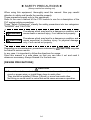
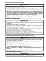
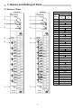
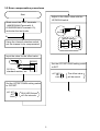
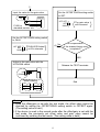
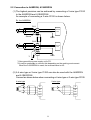
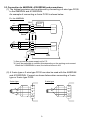
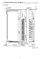
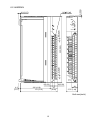
Pt100 Input Module User’s Manual (Installation) A68RD3N/4N A1S62RD3N/4N Thank you for buying the Mitsubishi general-purpose programmable logic controller MELSEC Series Prior to use, please read both this manual and detailed manual thoroughly and familiarize yourself with the product. MODEL A68/A1S62RD-U-HW MODEL 13JT68 CODE IB(NA)-0800202-A(0203)MEE 2002 MITSUBISHI ELECTRIC CORPORATION ! SAFETY PRECAUTIONS ! (Always read before starting use) When using this equipment, thoroughly read this manual. Also pay careful attention to safety and handle the module properly. These precautions apply only to this equipment. Refer to the user’s manual of the CPU module to use for a description of the PLC system safety precautions. These "Safety Precautions" classify the safety precautions into two categories: "DANGER" and "CAUTION". DANGER Procedures which may lead to a dangerous condition and cause death or serious injury, if not carried out properly. CAUTION Procedures which may lead to a dangerous condition and cause superficial to medium injury, or physical damage only, if not carried out properly. CAUTION may also Depending on circumstances, procedures indicated by be linked to serious results. In any case, it is important to follow the directions for usage. Store this manual in a safe place so that you can take it out and read it whenever necessary. Always forward it to the end user. [DESIGN PRECAUTIONS] CAUTION ! Do not bunch the control wires or communication cables with the main circuit or power wires, or install them close to each other. They should be installed 100mm (3.9inch) or more from each other. Not doing so could result in noise that would cause erroneous operation. A-1 [INSTALLATION PRECAUTIONS] CAUTION ! Use each module in an environment as specified in the “general specification” in the detailed manual. Using the PLC outside the range of the general specifications may result in electric shock, fire or malfunction, or may damage or degrade the module. ! Before mounting the module, insert the module fixing hook at the bottom of the module into the fixing hole in the base unit. (The AnS series modules must be screwed to the base unit to the specified torque.) Improper mounting of the module can cause a malfunction, failure or drop. ! Do not touch the conductive area or electronic parts of the module directly. Doing so can cause the module to malfunction or fail. [WIRING PRECAUTIONS] CAUTION ! Always ground the FG terminal and SLD terminal to the protective ground conductor. Not doing so can cause a malfunction. ! Carry out wiring to the PLC correctly, checking the rated voltage and terminal arrangement of the product. Using a power supply that does not conform to the rated voltage, or carrying out wiring incorrectly, will cause fire or failure. ! Tighten the terminal screws to the stipulated torque. Loose screws will cause short circuits, fire, or malfunctions. ! Make sure that no foreign matter such as chips or wiring offcuts gets inside the module. It will cause fire, failure or malfunction. [STARTING AND MAINTENANCE PRECAUTIONS] CAUTION ! Do not touch the terminals before switching power off externally in all phases. Doing so can cause a malfunction. ! Start cleaning or terminal screw retightening after switching power off externally in all phases. Not doing so can cause a malfunction. ! Do not disassemble or modify any module. This will cause failure, malfuntion, injuries, or fire. ! Mount or dismount the module after switching power off externally in all phases. Not doing so can cause the module to fail or malfunction. [DISPOSAL PRECAUTIONS] CAUTION ! When disposing of this product, treat it as industrial waste. A-2 Revisions * The manual number is noted at the lower left of the back cover. Print Date Mar,2002 *Manual Number IB(NA)-0800202-A Revision First printing This manual confers no industrial property rights or any rights of any other kind, nor does it confer any patent licenses. Mitsubishi electric Corporation cannot be held responsible for any problems involving industrial property rights which may occur as a result of using the contents noted in this manual. 2002 MITSUBISHI ELECTRIC CORPORATION A-3 CONTENTS 1. Overview ........................................................................................................1 2. Specification ..................................................................................................1 2.1 Performance specifications ......................................................................1 2.2 Specifications when platinum resistance bulb is connected......................2 3. Names and Setting of Parts ..........................................................................3 3.1 Names of Parts.........................................................................................3 3.2 Error compensation procedures ...............................................................5 4. Handling.........................................................................................................7 5. Wiring.............................................................................................................7 5.1 Precautions for connecting .......................................................................7 5.2 Connection to A68RD3N, A1S62RD3N ....................................................8 5.3 Connection to A68RD4N, A1S62RD4N and precautions..........................9 6. External Dimension Diagram........................................................................11 6.1 A68RD3N ...............................................................................................11 6.2 A68RD4N ...............................................................................................12 6.3 A1S62RD3N ...........................................................................................13 6.4 A1S62RD4N ...........................................................................................14 About the Manuals The following manuals are also related to this product. Order them if necessary. Detailed Manual Manual name Type A68RD3N/4N, A1S62RD3N/4N Pt100 Input Module User’s Manual A-4 Manual No. (Model code) SH-080193 (13JR46) 1. Overview This manual explains the specifications and part names of: • Pt100 Input Module Type A68RD3N (hereafter abbreviated to the A68RD3N) • Pt100 Input Module Type A68RD4N (hereafter abbreviated to the A68RD4N) • Pt100 Input Module Type A1S62RD3N (hereafter abbreviated to the A1S62RD3N) • Pt100 Input Module Type A1S62RD4N (hereafter abbreviated to the A1S62RD4N) which are used with the MELSEC-A series PLC CPU module (hereafter abbreviated to the PLC CPU). (The A68RD3N, A68RD4N, A1S62RD3N and A1S62RD4N are generically abbreviated to the RD3N/4N.) 2. Specification 2.1 Performance specifications Item Measuring method Output (temperature equivalent) Usable platinum temperature measuring resistors Pt100 Measured temperature ranges JPt100 Accuracy Resolution Conversion speed Number of analog input points Temperature detecting output current Insulation system Insulation resistance Broken wire detection Number of occupied I/O points Connection terminals Applicable wire size Applicable crimping terminals Cable across RD3N/4N - platinum temperature measuring resistor Internal current consumption (5VDC) Weight Outline dimensions Specifications A68RD4N A1S62RD3N A1S62RD4N 4-wire system 3-wire system 4-wire system 16-bit, signed binary data (-1800 to 6000: Value to first decimal place 10 times) 32-bit, signed binary data (-180000 to 600000: Value to third decimal places 1000 times) Pt100 (JIS C1604-1997, IEC 751-am2, JIS C1604-1989, DIN 43760-1980) JPt100 (JIS C1604-1981) -180 to 600 (27.10 to 313.71Ω) -180 to 600 (25.80 to 317.28Ω) 1% (accuracy relative to full-scale) 0.025 40ms / 1channel 8 channels/1 module 2 channels/1 module A68RD3N 3-wire system 1mA Across platinum temperature measuring resistor input - PLC power supply: Photocoupler-insulated Across platinum temperature measuring resistor input - channel: Non-insulated Across platinum temperature measuring resistor input - PLC power supply: 500VAC for 1 minute Detected channel Batch-detected Detected channel Batch-detected by channel on all channels by channel on all channels 32 points 38-point terminal block 20-point terminal block 2 2 0.75 to 2mm 0.75 to 1.5mm V1.25-3, V1.25-YS3A, V2-S3, V2-YS3A Refer to Section 2.2. 0.94A 0.43kg 0.41A 0.43kg 250(H)37.5(W)131(D)mm 1 0.49A 0.27kg 0.39A 0.27kg 130(H)34.5(W)107.4(D)mm 2.2 Specifications when platinum resistance bulb is connected (1) For A68RD3N and A1S62RD3N Make sure that the conductor resistance value between the Pt100 and A68RD3N/A1S62RD3N is 10 [Ω] or less per wire. All channels have the same specifications. 10 or 1) Conductor less A Pt100 2) A68RD3N A1S62RD3 B Wire so that the following is satisfied: 1) Conductor resistance value 10 ( ) 2) Conductor resistance value 10 ( ) 3) Conductor resistance value 10 ( ) b SLD 3) (2) For A68RD4N and A1S62RD4N Make sure that the total resistance value of the conductors over which the current passes is 70 [Ω] or less. [Example] To connect Pt100 to both CH.1 and CH.2 (A1S62RD4N) 1) Conductor a1 A1S62RD4N CH.1 Wire so that 1) + 2) + 3) + 4) + 5) A1 70 ( ) Pt100 B1 2) b1 4) 3) SLD a2 CH.2 A2 Pt100 B2 b2 5) The arrow SLD 2 indicates the current flow. 3. Names and Setting of Parts 3.1 Names of Parts A68RD3N 1) A68RD4N 1) RUN CH. 2) 2) OFFSET SET GAIN 3) 6) 1 2 3 4 5 6 7 8 DOWN 1 5) 2 A1 B1 b1 SLD A2 B2 b2 SLD A3 B3 b3 SLD A4 B4 b4 SLD A5 B5 b5 SLD A6 B6 b6 SLD A7 B7 b7 SLD A8 B8 b8 SLD UP 4) DOWN TEST CH. OFFSET SET GAIN 3) UP 4) 5) RUN CH. 3 4 5 6) TEST CH. 1 6 7 8 2 9 10 11 12 3 13 14 15 16 4 17 18 19 20 5 21 22 23 24 6 25 26 27 28 7 29 30 31 32 8 33 34 35 1 a1 A1 B1 b1/a2 SLD A2 B2 b2/a3 SLD A3 B3 b3/a4 SLD A4 B4 b4/a5 SLD A5 B5 b5/a6 SLD A6 B6 b6/a7 SLD A7 B7 b7/a8 SLD A8 B8 b8 SLD 36 7) ANALOG GND FG INPUT PT100 3 4 5 6 7 8 9 10 11 12 13 14 15 16 17 18 19 20 21 22 23 24 25 26 27 28 29 30 31 32 33 34 35 36 37 38 2 7) ANALOG GND FG INPUT PT100 3 37 38 Terminal Block Layout Terminal number Signal A68RD A68RD name 3N 4N 1 TEST 2 TEST 3 Blank a1 4 A1 5 B1 6 b1 b1/a2 7 SLD 8 A2 9 B2 10 b2 b2/a3 11 SLD 12 A3 13 B3 14 b3 b3/a4 15 SLD 16 A4 17 B4 18 b4 b4/a5 19 SLD 20 A5 21 B5 22 b5 b5/a6 23 SLD 24 A6 25 B6 26 b6 b6/a7 27 SLD 28 A7 29 B7 30 b7 b7/a8 31 SLD 32 A8 33 B8 34 b8 35 SLD 36 Blank 37 ANALOG GND 38 FG A1S62RD3N 1) OFF SET SET GAIN RUN 2) CH1 UP CH2 DOWN A1S62RD4N 3) 1) 4) 2) OFF SET SET GAIN RUN CH1 UP CH2 DOWN 1 5) 2 TEST 3 1 5) 2 TEST 3 4 4 5 5 6 C H 1 6) A1 B1 b1 SLD 7 8 9 6) a1 A1 C H 1 B1 b1 10 SLD 11 12 C H 2 A2 B2 b2 SLD AG 7) FG No. 13 15 B2 b2 16 SLD 17 18 19 20 Name Operation status display LED (RUN LED) 2) Channel selection switch 3) OFFSET/GAIN setting switch 4) UP/DOWN switch 5) Test mode terminal Pt100 connection terminal Analog/ground terminal 7) C H 2 14 1) 6) a2 A2 AG 7) FG 6 7 8 9 10 11 12 13 14 15 16 17 18 19 20 3) 4) Terminal Block Layout Terminal number Signal A1S62 A1S62 name RD3N RD4N 1 TEST 2 Blank 3 TEST 4 Blank 5 Blank 6 Blank 7 a1 Blank 8 A1 9 B1 10 b1 11 SLD 12 Blank 13 a2 Blank 14 A2 15 B2 16 b2 17 SLD 18 Blank 19 AG 20 FG Details ON : In normal operation Normal Flicker : Write data error occurring mode OFF : 5VDC power OFF or watch dog timer error occurring Flicker : When the OFFSET/GAIN setting switch is set to Test OFFSET or GAIN, the LED will flicker at 0.5 mode second intervals. OFF : OFFSET/GAIN setting switch set to SET. Selects the channel for adjusting the offset and gain for error compensation. (When A68RD3N/4N is used, the 0, 9 position setting is not managed.) Factory-Set A68RD3N/4N : 0 A1S62RD3N/4N : CH1 Sets the offset value and gain value for the test mode. Factory-Set : SET 1) OFFSET position : Offset value compensation mode 2) GAIN position : Gain value compensation mode 3) SET position : Offset value/gain value save mode The temperature detection value at the time the switch is changed from the OFFSET/ GAIN position to the SET position is saved in the RD3N/4N internal memory as the offset/gain value. Increments/decrements the offset value/gain value for the channel being used at the following rate. 1) ON for less than 1.5 seconds: Increments/decrements in 0.025 units. 2) ON for 1.5 seconds or more: Increments/decrements in 0.1 unit every 0.04 seconds. Short the terminals when making error compensation. Connect the Pt100. Use to provide a separate ground. 4 3.2 Error compensation procedures Start Adjust to the offset value with the UP/DOWN switch. Short-circuit the TEST terminals (A68RD3N/4N:Terminals1-2, A1S62RD3N/4N:Terminals1-3), and enter the test mode. UP DOWN A) Buffer memory Using the channel selection switch, set the channel to be compensated. -497 -500 Input the value for the offset value. -50[ ] RD3N/4N Set the OFFSET/GAIN setting switch to SET. Pt100 or standard resistor, etc. OFF SET SET GAIN The offset value will be saved. Set the OFFSET/GAIN setting switch to OFFSET. OFF SET SET GAIN 1) RUN LED flickers at 0.5s intervals. 5 1) Input the value for the gain value. 80[ ] Set the OFFSET/GAIN setting switch to SET. RD3N/4N OFF SET SET GAIN Pt100 or standard resistor, etc. The gain value will be saved. Set the OFFSET/GAIN setting switch to GAIN. No A) RUN LED flickers at 0.5s intervals. OFF SET SET GAIN Is compensation of the channel being used completed? YES Adjust to the gain value with the UP/DOWN switch. Release the TEST terminals. UP DOWN Buffer memory 797 End 800 Point 1) Once the offset/gain is set with the test mode, the offset value cannot be checked by setting the OFFSET/GAIN setting switch to OFFSET again. (The setting value is held.) 2) If the device is used in the normal mode after the offset/gain is set with the test mode, the previously set offset value and gain value cannot be confirmed by entering the test mode. (The setting value is held.) 6 4. Handling (1) The main case and terminal block are made of resin, so do not drop it or apply strong impacts. (2) Do not remove the module's PCB from the case. Failure to observe this could lead to faults. (3) Make sure that foreign matter, such as wire scraps, do not enter the module during wiring. Remove any foreign matter that enters. (4) Tighten the module installation screws and terminal screws within the following ranges. Screw position Module installation screw Terminal block installation screw Terminal block terminal screw Tightening torque range A68RD3N/4N is used A1S62RD3N/4N is used 78 to 118N•cm 78 to 118N•cm (M4 screw) (M4 screw) 39 to 59N•cm 59 to 88N•cm (M3 screw) (M3.5 screw) 78 to 118N•cm 78 to 118N•cm (M4 screw) (M4 screw) 5. Wiring 5.1 Precautions for connecting Precautions for connecting the Pt100 to the RD3N/4N, and the connection methods are described below. (1) Use separate cables for the AC and RD3N/4N external input signal, and make sure that the cable is not affected by the AC side surge or inductance. (2) Do not lay the cables near or with the main circuit wires, high-voltage wires or load wires other than those from the PLC. Failure to observe this will increase the effect of noise, surge and inductance. (3) Ground the shield wire or shield clamp shield to one point on the PLC side. Note that in some cases, grounding these at an external source may be preferable depending on the state of the external noise. 7 5.2 Connection to A68RD3N, A1S62RD3N (1) The highest precision can be achieved by connecting a 3-wire type Pt100 to the A68RD3N and A1S62RD3N. An example of connecting a 3-wire Pt100 is shown below. Ex. the A68RD3N CH1 A B B A B b SLD Internal circuit Shield GND CH8 A B B A B b SLD *2 Internal circuit ANALOG GND FG GND *1 *1 Also ground the power supply unit's FG. *2 It may be preferable to connect this depending on the working environment. When the A1S62RD3N is used, the terminal name is AG. (2) A 4-wire type or 2-wire type Pt100 can also be used with the A68RD3N and A1S62RD3N. Connect as shown below when connecting a 4-wire type or 2-wire type Pt100. 4-wire type 2-wire type A A A A A B B B B B b b SLD SLD 8 5.3 Connection to A68RD4N, A1S62RD4N and precautions (1) The highest precision can be achieved by connecting a 4-wire type Pt100 to the A68RD4N and A1S62RD4N. An example of connecting a 4-wire Pt100 is shown below. Ex. the A68RD4N CH1 A A B B a A B b SLD Constant current circuit Internal circuit Shield CH8 A A B B a A B b SLD Internal circuit *2 ANALOG GND FG GND *1 *1 Also ground the power supply unit's FG. *2 It may be preferable to connect this depending on the working environment. When the A1S62RD4N is used, the terminal name is AG. (2) A 3-wire type or 2-wire type Pt100 can also be used with the A68RD4N and A1S62RD4N. Connect as shown below when connecting a 3-wire type or 2-wire type Pt100. 3-wire type 2-wire type a a A A A B B B B B b b SLD SLD A 9 (3) Precautions for connection to A68RD4N and A1S62RD4N The following are the precautions for connection of Pt100 to the A68RD4N and A1S62RD4N. (a) Perform wiring so that there is continuity between the following terminals. When all channels are used on A68RD4N CH.1 CH.2 CH.3 CH.4 CH.5 CH.6 CH.7 CH.8 a1 A1 B1 b1/a2 A2 B2 b2/a3 A3 B3 b3/a4 A4 B4 b4/a5 A5 B5 b5/a6 A6 B6 b6/a7 A7 B7 b7/a8 A8 B8 b8 When all channels are used on A1S62RD4N CH.1 CH.2 a1 A1 B1 b1 a2 A2 B2 b2 (b) Skip the terminals of the unused channels. When only CH1, 2, 3 and 6 are used on A68RD4N CH.1 CH.2 CH.3 CH.4 CH.5 CH.6 CH.7 CH.8 a1 A1 B1 b1/a2 A2 B2 b2/a3 A3 B3 b3/a4 A4 B4 b4/a5 A5 B5 b5/a6 A6 B6 b6/a7 A7 B7 b7/a8 A8 B8 b8 *Always wire terminals a1 and b8. When only CH1 is used on A1S62RD4N CH.1 CH.2 a1 A1 B1 b1 a2 A2 B2 b2 *Always wire terminals a1 and b2. Point Always specify "conversion disable" for the channels not connected with Pt100. When the channels not connected with Pt100 are specified as "conversion enable", the wire break detection flag turns ON if a wire break does not occur on the channel connected with PT100. 10 6. External Dimension Diagram 4.2 (0.17) 2 (0.08) 6.1 A68RD3N N3 0.5 6 Installation screw A68RD3N RUN CH. OFFSET SET GAIN UP 8.6 (0.34) DOWN 1 TEST CH. 2 A1 250 (9.85) 1 2 3 4 5 7.2 (0.28) 6 7 8 B1 b1 SLD A2 B2 b2 SLD A3 B3 b3 SLD A4 B4 b4 SLD A5 B5 b5 SLD A6 B6 b6 SLD A7 B7 b7 SLD A8 B8 b8 SLD 3 4 5 6 7 8 9 10 11 12 13 14 15 16 17 18 19 20 21 22 23 24 25 26 27 28 29 30 31 32 33 34 35 36 ANALOG GND FG 37 38 INPUT PT100 6(0.24) 4.2 (0.17) 106 (4.18) 10(0.39) 25 (0.99) 131 (5.16) 18 (0.71) 37.5 (1.48) Unit:mm(inch) 11 4.2 (0.17) 2 (0.08) 6.2 A68RD4N N3 0.5 6 Installation screw A 68RD4N RUN CH. OFFSET SET GAIN UP 8.6 (0.34) DOWN 1 TEST CH. a1 A1 1 250 (9.85) 2 3 4 5 6 7.2 (0.28) 7 8 B1 b1/a2 SLD A2 B2 b2/a3 SLD A3 B3 b3/a4 SLD A4 B4 b4/a5 SLD A5 B5 b5/a6 SLD A6 B6 b6/a7 SLD A7 B7 b7/a8 SLD A8 B8 b8 SLD 2 3 4 5 6 7 8 9 10 11 12 13 14 15 16 17 18 19 20 21 22 23 24 25 26 27 28 29 30 31 32 33 34 35 36 ANALOG GND FG 37 38 INPUT PT100 6(0.24) 4.2 (0.17) 106 (4.18) 10(0.39) 25 (0.99) 131 (5.16) 18 (0.71) 37.5 (1.48) Unit:mm(inch) 12 6.3 A1S62RD3N A1S62RD3N 130 (5.12) RUN 6.5 (0.26) 93.6 (3.69) 7.3 (0.29) OFF SET SET GAIN CH1 UP CH2 DOWN 0 1 2 3 4 5 6 7 8 9 A B C D E F 34.5 (1.36) Unit:mm(inch) 13 6.4 A1S62RD4N A1S62RD4N 130 (5.12) RUN 6.5 (0.26) 93.6 (3.69) 7.3 (0.29) OFF SET SET GAIN CH1 UP CH2 DOWN 0 1 2 3 4 5 6 7 8 9 A B C D E F 34.5 (1.36) Unit:mm(inch) 14 Warranty Mitsubishi will not be held liable for damage caused by factors found not to be the cause of Mitsubishi; machine damage or lost profits caused by faults in the Mitsubishi products; damage, secondary damage, accident compensation caused by special factors unpredictable by Mitsubishi; damages to products other than Mitsubishi products; and to other duties. For safe use " This product has been manufactured as a general-purpose part for general industries, and has not been designed or manufactured to be incorporated in a device or system used in purposes related to human life. " Before using the product for special purposes such as nuclear power, electric power, aerospace, medicine or passenger movement vehicles, consult with Mitsubishi. " This product has been manufactured under strict quality control. However, when installing the product where major accidents or losses could occur if the product fails, install appropriate backup or failsafe functions in the system. Country/Region Sales office/Tel U.S.A Mitsubishi Electric Automation Inc. 500 Corporate Woods Parkway Vernon Hills, IL 60061 Tel : +1-847-478-2100 Brazil MELCO-TEC Rep. Com.e Assessoria Tecnica Ltda. Av. Rio Branco, 123-15 ,and S/1507, Rio de Janeiro, RJ CEP 20040-005, Brazil Tel : +55-21-221-8343 Germany Mitsubishi Electric Europe B.V. German Branch Gothaer Strasse 8 D-40880 Ratingen, GERMANY Tel : +49-2102-486-0 U.K Mitsubishi Electric Europe B.V. UK Branch Travellers Lane, Hatfield, Herts., AL10 8XB,UK Tel : +44-1707-276100 Italy Mitsubishi Electric Europe B.V. Italian Branch Centro Dir. Colleoni, Pal. Perseo - Ingr.2 Via Paracelso 12, 20041 Agrate B., Milano, Italy Tel:+39-039-60531 Spain Mitsubishi Electric Europe B.V. Spanish Branch Carretera de Rubi 76-80 08190 - Sant Cugat del Valles, Barcelona, Spain Tel:+34-935-653135 South Africa Circuit Breaker Industries LTD. Private Bag 2016, Isando 1600, Johannesburg, South Africa Tel : +27-11-928-2000 Hong Kong Ryoden Automation Ltd. 10th Floor, Manulife Tower, 169 Electric Road, North Point, HongKong Tel : +852-2887-8870 Country/Region Sales office/Tel China Ryoden International Shanghai Ltd. 3F Block5 Building Automation Instrumentation Plaza 103 Cao Bao Rd. Shanghai 200233 China Tel : +86-21-6475-3228 Taiwan Setsuyo Enterprise Co., Ltd. 6F., No.105 Wu-Kung 3rd.RD, Wu-Ku Hsiang, Taipei Hsine, Taiwan Tel : +886-2-2299-2499 Korea HAN NEUNG TECHNO CO.,LTD. 1F Dong Seo Game Channel Bldg., 660-11, Deungchon-dong Kangsec-ku, Seoul, Korea Tel : +82-2-3668-6567 Singapore Mitsubishi Electric Asia Pte, Ltd. 307 ALEXANDRA ROAD #05-01/02, MITSUBISHI ELECTRIC BUILDING SINGAPORE 159943 Tel : +65-473-2480 Thailand F. A. Tech Co.,Ltd. 898/28,29,30 S.V.City Building,Office Tower 2,Floor 17-18 Rama 3 Road, Bangkpongpang, Yannawa, Bangkok 10120 Tel : +66-2-682-6522 Indonesia P.T. Autoteknindo SUMBER MAKMUR Jl. Muara Karang Selatan Block A Utara No.1 Kav. No.11 Kawasan Industri/ Pergudangan Jakarta - Utara 14440 Tel : +62-21-663-0833 India Messung Systems Put,Ltd. Electronic Sadan NO:111 Unit No15, M.I.D.C BHOSARI,PUNE-411026 Tel : +91-20-7128927 Australia Mitsubishi Electric Australia Pty. Ltd. 348 Victoria Road, PostalBag, No 2, Rydalmere, N.S.W 2116, Australia Tel : +61-2-9684-7777 HEAD OFFICE : 1-8-12, OFFICE TOWER Z 14F HARUMI CHUO-KU 104-6212, JAPAN NAGOYA WORKS : 1-14, YADA-MINAMI5, HIGASHI-KU, NAGOYA, JAPAN When exported from Japan, this manual does not require application to the Ministry of Economy, Trade and Industry for service transaction permission. Specifications subject to change without notice. Printed in Japan on recycled paper.