1
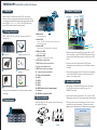
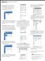
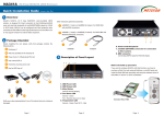
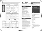
● NR330A-IP4
Quick Installation Guide
GbE iSCSI to SATA II/III Chassis
First Edition, October 2011
Netstor Technology Co., Ltd.
6 F, N o . 1 , Al l e y 1 6 , L a n e 2 3 5 , Ba o q i a o R d . , Xindian Distr ict, New Taipei City 231- 45, Taiwan, R.O.C.
Te l : + 8 8 6 -2 -2 9 1 7 -1 5 0 0 Fa x : + 8 8 6 -2 -2 9 1 8 -1260 E- m ail: sales@netstor .com .tw
NR330A-IP4
GbE iSCSI to SATA II/III Chassis
1. Overview
5. Product Connection
8
6 7
Management
PC
iSNS server
Host / Server (Optional)
RS-232
2. Package Checklist
Before installing this unit, verify that package contains the
following items.
17
18
Netstor’s GbE iSCSI enclosure uses Intel IOP 341, 64-bit Xscale
processor as the core engine that delivers highest performance while
running with quad Gigabit iSCSI channels and supports hardware RAID
levels of RAID 0, 1, 0+1, 3, 5, 6, 10, 30, 50, 60 & JBOD with a wide
range of RAID function selection for data protection.
9
10
1. Mute button
11
Switch
16 12 14
13 15
Gigabit switch
。Reset for buzzer beeping
2. Status LED
。Normal – green; failure – red (Fan fails, over-temperature occurs, or
HDD/power supply failure)
3. Access LED
RS-232
。HDD no access – no light; HDD accessing – flashing green
A
B
Enclosure x 1
HDD tray
(installed on enclosure) x 16
4. HDD power LED
1. Connect one end of the Gigabit Ethernet cable to GbE 1, GbE 2,
GbE 3, and GbE 4 on rear of the NR330A-IP4 enclosure, and the
other end of the Gigabit Ethernet cable to the GbE ports on GbE
switch.
。white - power on indicator
5. HDD status LED
。flashing blue – busy (HDD accessing) indicator
6. LCD (liquid crystal display)
7. ESC (Escape) (control panel button)
2. Connect one end of the Ethernet cable to RJ45 Ethernet
management port and, and the other end of the Ethernet cable to
the switch.
8. ▲ (Up) (control panel button)
C
Power cord x 2
D
Hard drive mounting screw
package x 1
Green IT makes
Green Earth
NetStor Technology Co. Ltd.
www.netstor.com.tw
E
F
Key for HDD tray x 2
CD user’s manual x 1
Notify your sales representative if any of the above items is missing
or damaged.
Install each hard drive into the drive trays and fasten using
the supplied HDD screws.
1 2 3
HDD1
HDD5
HDD9
HDD13
▼ (Down) (control panel button)
Power cord receptacles
GbE 1
GbE 2
GbE 3
GbE 4
RJ45 Ethernet port for management
Console
RS-232 for connection UPS
4. Disk Installation
3. Panel Layout
4
5
9. ENT (Enter) (control panel button)
10.
11.
12.
13.
14.
15.
16.
17.
18.
HDD2
HDD6
HDD10
HDD14
HDD3
HDD7
HDD11
HDD15
HDD4
HDD8
HDD12
HDD16
Step 1
Net cable
RS-232 cable
Step 2
3. Plug one end of the power cord to the two power cord receptacles
on rear of the NR330A-IP4 enclosure, and the other end of the
power cord to the power outlets.
6. Quick RAID Setting
1. After you turn on the NR330A-IP4, there will be an IP address
(e.g. 192.168.xxx.xxx) shown in the LCD on rear of the
NR330A-IP4 enclosure.
2. Open the web browser (Internet Explorer…etc.), and key in the IP
address shown from the LCD into the web browser, and press enter.
3. The entry screen of the web GUI will be shown. Then you key in
the default user name and password. The default user name is:
admin, and the default password is: 1234, and then press Login.
NR330A-IP4
GbE iSCSI to SATA II/III Chassis
11. Right-click the RAID volume, and select New Simple Volume
Wizard. Complete the steps shown in the New Simple Volume
Wizard, and the RAID volume will be formatted.
4. After you enter the web GUI, to perform a quick setup of RAID,
click Quick installation at the top on the left side of the screen.
Then you are able to select a RAID level (e.g. RAID 0, 1, 3, 5, 6,
0 + 1…etc.) for NR330A-IP4. After you have selected a RAID
level, press Confirm to proceed to the next step.
12. Click Device Manager on the left side of the window of Computer
Management, and then click Disk drives. You will see “Netstor
iSCSI-Device SCSI Disk Device” (indicating NR330A-IP4) shown
under “Disk drives”.
5. Information about the RAID level and the volume size that are going
to be created will be shown on the screen. Press Confirm to finish
the setup. After you press Confirm, the RAID level and the volume
size will be created.
6. Click iSCSI configuration, and then click NIC. You will see LAN1,
LAN2, LAN3, and LAN4 with its default IP address and Gateway
address. To change each LAN’s IP address and Gateway address
for your network environment, click IP settings for iSCSI ports, and
key in the IP address and Gateway address, and then click Confirm.
9. Select Targets in iSCSI Initiator. Click the item “iqn.2001-10.tw
.com.netstor:iscsi-device-000c10021:default-target” shown in the
Discovered targets, and then press Connect. The window of
“Connect To Target” will pop up. Select “Add this connection to
the list…” and “Enable multi-path”, and click OK. After you press
OK, the status of the item will become “Connected”.
13. Click Device Manager on the left side of the window of Computer
Management, and then click Disk drives. You will see “Netstor
iSCSI-Device SCSI Disk Device” (indicating NR330A-IP4) shown
under “Disk drives”.
7. After the IP address and Gateway address have been changed,
remember those addresses for iSCSI Initiator’s Target portals in the
Discovery section in iSCSI Initiator.
10. Right-click Computer, and select Manage. After the window of
Computer Management shows up. Click Disk Management. The
RAID volume (Unallocated) you created on NR330A-IP4 will be
shown at the bottom part in the window of Computer Management.
For detailed configuration of NR330A-IP4, please refer to
NR330A-IP4’s user’s manual.
If you have any questions, please contact your regional distributor,
or Netstor Technology, Taiwan.
8. Open the iSCSI Initiator. Select Discovery, and then click Discover
Portal. Key in the IP addresses shown from iSCSI configuration
> NIC for LAN1, LAN2, LAN3, and LAN4.
Netstor Technology Co., Ltd.
6F, No. 1, Alley 16, Lane 235, Baoqiao Rd., Xindian District,
New Taipei City 231-45, Taiwan, R.O.C.
Tel: +886-2-2917-1500 Fax: +886-2-2918-1260
E-mail: [email protected]