1
ISDN PBX-System
AS 281 All-In-One
AS 35
AS 35 All-In-One
Manual
Saftey Notes
- Installation and Maintenance of the System only by trained personnel.
- Important! To prevent personal injury and damage to equipment please ensure that the
system is properly earthed and that the appropriate cable is connected in the mains plug.
- The System must be installed horizontal so that the connection panel is on the right hand
side.
- Do not connect or disconnect any PSTN lines during a thunderstorm.
- Install lines and extensions in such a way that no one walks or trips over them.
- Disconnect the System from the mains supply before opening the connection panel.
Before connection of lines and extensions please ensure that the system is unplugged
from the mains supply. DANGER!
- Preventive measure! Before carrying out any installation work, please touch briefly the
PC/Printer socket of the telephone system. This will discharge any possible electrostatic
charges, thus protecting the telephone system’s electrostatically sensitive components.
- Do not allow liquids to enter the system as short-curcuits may occur.
- No liability will be accepted for consequential damages such as an unintentional
continued connection of a line.
- The telephone system will not operate in case of power failure and you will not be able to
make any type of call.
The AS 35 is indented for the connection to Basic Rate ISDN lines (DSS1, Point to Point, System Access, or Point to Multi Point, Standard Access).
The AS 281 All-In-One and AS 35 All-in-One can be connected to Basic Rate ISDN lines
(DSS1, Point to Point, System Access, or Point to Multi Point, Standard Access) and may
also be connected to analogue exchange lines.
Should you operate the AS 35 All-In-One on an analogue exchange line, then please ensure
that your telephone service provider has meter pulse sending disabled as this may
otherwise interfere with speech quality of a call.
You may connect any equipment which has been approved for the connection to the Public
Switched Telephone Network (PSTN) to the extension port of the system.
Any DSS1 ISDN device which has been approved for the connection to the ISDN telephone
exchange may be connected to the internal SO Bus. In addition you may connect up to two
digital AGFEO System Phones to each SO Bus.
Any other use of the telephone system which is not listed or described is prohibited.
The telephone system has been issued with a universal connection licence.
The system fulfils the specified conformity and safety regulations.
About This Manual
The instruction is valid for the default setting of the system. If the system should be
modified due to software made available through the manufacturer then it may be possible
that sections of the instruction manual become invalid. All listed ISDN features will be
supported by the system. However, some features may not be available through the
Network Operator.
Introduction
Tables of Content
Introduction
Saftey Notes .......................................................................................................................... E - 2
About This Manual ................................................................................................................ E - 2
The AS 281 All-In-One Telephone System ............................................................................. E - 6
The AS 35 Telephone System ................................................................................................ E - 7
The AS 35 All-In-One Telephone System ............................................................................... E - 8
Important notes on using analogue equipment .................................................................... E - 9
CTI - computer telephony integration ................................................................................. E - 11
System telephones .............................................................................................................. E - 12
Pictograms and Buttons ..................................................................................................... E - 12
Installation
Check contents of delivery ..................................................................................................... I - 3
Wall Mounting ........................................................................................................................ I - 4
Open Connection Cover .......................................................................................................... I - 4
Connect Analogue Extensions ............................................................................................. I - 10
External S0-Connection Fixed S0 ......................................................................................... I - 10
Internal S0-Connection ........................................................................................................ I - 12
Connect the AS 281 All-in-one/ ............................................................................................ I - 13
AS 35 All-In-One to an analogue exchange line ................................................................... I - 13
Door Phone .......................................................................................................................... I - 14
Commissioning .................................................................................................................... I - 15
Tecnical Data AS 281 All-In-One .......................................................................................... I - 17
Tecnical Data AS 35 .............................................................................................................. I - 18
Tecnical Data AS 35 All-In-One ............................................................................................ I - 19
Operation
System Phone ST 40 ............................................................................................................. 1 - 2
Notes on using this Manual .................................................................................................. 1 - 4
System Telephones - Settings ............................................................................................... 1 - 4
Button Assignment ............................................................................................................... 1 - 7
Function Buttons - Freely programmable Function Buttons (overview) ................................ 1 - 8
External Line Access ........................................................................................................... 1 - 10
Making a Call ...................................................................................................................... 1 - 11
External Access with specific MSN ..................................................................................... 1 - 13
Reserving an Outside Line .................................................................................................. 1 - 13
Accepting Incoming Calls .................................................................................................... 1 - 15
Call Transfer ....................................................................................................................... 1 - 17
Call Waiting/ Callback when free ........................................................................................ 1 - 19
Transfer an Outside Line ..................................................................................................... 1 - 19
Call Waiting ......................................................................................................................... 1 - 21
Call Pick Up ........................................................................................................................ 1 - 22
Call Log ............................................................................................................................... 1 - 23
Do Not Disturb .................................................................................................................... 1 - 25
Switching between Day and Night Service .......................................................................... 1 - 26
Switching Call Forwarding (Extension Call Forwarding) on/off ........................................... 1 - 28
Call Deflection - Forwarding a call during the ringing phase ............................................. 1 - 30
Reject a call during the ringing phase ................................................................................ 1 - 30
Auto Dialling (Hotline) ......................................................................................................... 1 - 31
E-3
Introduction
Tables of Content
Busy on Busy ......................................................................................................................
Voice Message .....................................................................................................................
Announcement ....................................................................................................................
To place a Call on Hold .......................................................................................................
Remote Dial Functions ........................................................................................................
Malicious Call Identification (MCID) ....................................................................................
Conference ..........................................................................................................................
Least Cost Routing (LCR) ....................................................................................................
Carrier Access Code – on a Call by Call basis ....................................................................
Call Split (Brokers Call) .......................................................................................................
switching between calls ......................................................................................................
Call Log ...............................................................................................................................
Parking a Call .....................................................................................................................
Baby Listening / Room Monitor ...........................................................................................
Enquiry ................................................................................................................................
Automatic Call Back ...........................................................................................................
View Extension Status .........................................................................................................
Set Extension Names ..........................................................................................................
Enter Names with number buttons ....................................................................................
Storing Phonebook Numbers .............................................................................................
(Central Dialling Memory) ...................................................................................................
Dialling Numbers from the Phone Book .............................................................................
Telephone Lock - Emergency/Direct Call (Baby Call) .........................................................
Appointment Call (Non-Recurring) .....................................................................................
Timer Control ......................................................................................................................
Switching over the door call variant ...................................................................................
Doorphone Diversion to External Number ..........................................................................
Operating the Doorphone and Door opener ........................................................................
Communicating a caller’s phone .......................................................................................
number on the internal S0 bus ...........................................................................................
Sending CLIP or COLP ........................................................................................................
Diversion from - Divert other ..............................................................................................
Extensions ...........................................................................................................................
Diversion to -diverting calls to another phone ....................................................................
Call Forwarding ...................................................................................................................
Display call charges ............................................................................................................
Print Call Charges ...............................................................................................................
System Redial .....................................................................................................................
Wake Up Call .......................................................................................................................
Single Button Dialling .........................................................................................................
Groups .................................................................................................................................
Account Codes ....................................................................................................................
Call Filter ............................................................................................................................
Call Through .......................................................................................................................
CLIP - Display Caller Number ............................................................................................
Keypad function ..................................................................................................................
Switchbox ............................................................................................................................
E-4
1 - 33
1 - 34
1 - 34
1 - 36
1 - 37
1 - 38
1 - 40
1 - 42
1 - 43
1 - 44
1 - 44
1 - 45
1 - 46
1 - 48
1 - 50
1 - 52
1 - 53
1 - 53
1 - 54
1 - 55
1 - 55
1 - 60
1 - 63
1 - 66
1 - 67
1 - 68
1 - 69
1 - 71
1 - 72
1 - 72
1 - 72
1 - 74
1 - 74
1 - 75
1 - 77
1 - 80
1 - 81
1 - 84
1 - 85
1 - 88
1 - 89
1 - 90
1 - 91
1 - 92
1 - 93
1 - 93
1 - 94
Introduction
Tables of Content
AIS-Module
Integrated AIS-Module .......................................................................................................... 2 - 1
Transferring Messages and Music-on-Hold ......................................................................... 2 - 4
Music on Hold (MoH) ............................................................................................................. 2 - 4
Messages .............................................................................................................................. 2 - 5
Greetings ............................................................................................................................... 2 - 5
Wake Up Call ......................................................................................................................... 2 - 6
Setting the Configuration Tool TK Suite ................................................................................ 2 - 7
Music on Hold ....................................................................................................................... 2 - 7
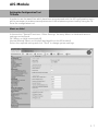
Announcement before Answer .............................................................................................. 2 - 8
Announcement before Answer with DDI (Auto Attendant) .................................................... 2 - 9
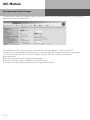
Welcome Message (Mode "Transfer") ................................................................................. 2 - 10
Time at which an Extension should ring ............................................................................. 2 - 10
Announcement during Ringing Phase ................................................................................ 2 - 10
Allocation of Welcom Message ........................................................................................... 2 - 10
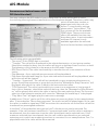
Allocation of On Hold Message ........................................................................................... 2 - 11
Allocation of Door Phone Announcements ......................................................................... 2 - 11
Allocation of Sensor Announcements ................................................................................. 2 - 11
Recording of Announcements from Sytem Phones ............................................................ 2 - 11
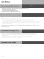
Standard Music ................................................................................................................... 2 - 12
Programming
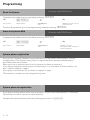
Programming via PC .............................................................................................................. 3 -3
Programming from the system telephone or a/b telephone .................................................. 3 -4
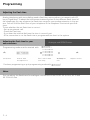
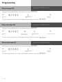
Adjusting the flash time ......................................................................................................... 3 -6
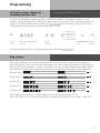
Setting the ringer rhythm for incoming external calls ........................................................... 3 -7
Variable call times of the TFE’s ............................................................................................. 3 -8
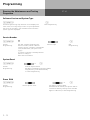
Protecting functions of the telecommunications (code numbers) ........................................ 3 -8
Maintenance/ Testing ........................................................................................................... 3 -11
System phone registration ................................................................................................... 3 -14
System phone deregistration ............................................................................................... 3 -14
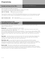
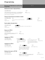
Remote setting - Remote configuration ............................................................................... 3 -15
Downloading new software .................................................................................................. 3 -17
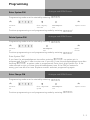
Transfer on Hang Up ............................................................................................................ 3 -18
Advanced Users Programming ............................................................................................ 3 -19
Programming tree ............................................................................................................... 3 -20
Communication via PC
Software Overview .............................................................................................................. PC - 3
Appendix
Glossary ................................................................................................................................ A - 2
Appendix ............................................................................................................................. A - 12
Tones ................................................................................................................................... A - 13
Index
Index ...................................................................................................................................... S - 2
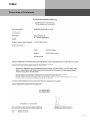
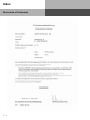
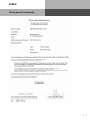
Declaration of Conformity ..................................................................................................... S - 5
E-5
Introduction
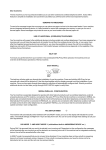
The AS 281 All-In-One Telephone System
The AS281 All-In-One is so much more then “just” a telephone system for the connection
to the analogue telephone exchange. With the option to select the operation of an internal
or external SO Bus the system may also be operated with a mixture of lines, analogue – or
ISDN lines.
The connection to Internet Telephony Providers to use services such as Voice over IP is also
possible without any problems. The AS 281 All-In-One will also support Voice over IP
services via an Analogue Telephone Adaptor (ATA) which allows access to the SIP Gateway
of the IP Provider. The port of the analogue exchange line will be connected to the output of
the ATA and therefore all extensions connected to the telephone system can make calls via
the IP network of the various providers.
The connection of the telephone adaptor (ATA) to the exchange line side of the telephone
system will offer the use of features like exchange line access, CTI, Call Diversion, Least
Cost Routing, CLIP etc. The familiar operation for the extension user remains unchanged.
Basic configuration of the AS 35 All-In-One:
-
2 Analogue Exchange Lines
1 SO Bus External (ISDN Line) or internal (Digital Phones)
8 POT Ports for analogue equipment of which 1 can be used for a door phone
1 PC Connection (RS232)
1 USB Port for PC programming
1 AIS Module (Audio Information System)
Software Package TK Suite Basic
Optional:
- AGFEO DECT SO Base via an internal SO Bus
Note
Some products may only be available in certain countries.
Please ask your dealer for further information.
E-6
Introduction
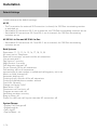
The AS 35 Telephone System
The AGFEO AS 35 is configured for up to 18 extensions and offers in addition an integrated
AIS Module. The AIS (Audio Information System) offers automatic announcements of
advertising, music on hold, door phones - or security messages and wake up calls.
Basic configuration of the AS 35:
-
1 SO Bus External (ISDN Line)
3 SO Bus External (ISDN Line) or internal (Digital Phones)
12 POT Ports for analogue equipment of which 1 can be used for a door phone
1 PC Connection (RS232)
1 USB Port for PC programming
1 AIS Module (Audio Information System)
Software Package TK Suite Basic
Optional
- AGFEO DECT SO Base via an internal SO Bus
Note
Some products may only be available in certain countries.
Please ask your dealer for further information.
E-7
Introduction
The AS 35 All-In-One Telephone
System
The AS 35 All-In-One is so much more then “just” a telephone system for the connection to
the analogue telephone exchange. With the option to select the operation of an internal or
external SO Bus the system may also be operated with a mixture of lines, analogue – or
ISDN lines.
The connection to Internet Telephony Providers to use services such as Voice over IP is also
possible without any problems. The AS 35 All-In-One will also support Voice over IP
services via an Analogue Telephone Adaptor (ATA) which allows access to the SIP Gateway
of the IP Provider. The port of the analogue exchange line will be connected to the output of
the ATA and therefore all extensions connected to the telephone system can make calls via
the IP network of the various providers.
The connection of the telephone adaptor (ATA) to the exchange line side of the telephone
system will offer the use of features like exchange line access, CTI, Call Diversion, Least
Cost Routing, CLIP etc. The familiar operation for the extension user remains unchanged.
Basic configuration of the AS 35 All-In-One:
-
2 Analogue Exchange Lines
2 SO Bus External (ISDN Line) or internal (Digital Phones)
12 POT Ports for analogue equipment of which 1 can be used for a door phone
1 PC Connection (RS232)
1 USB Port for PC programming
1 AIS Module (Audio Information System)
Software Package TK Suite Basic
Optional:
- AGFEO DECT SO Base via an internal SO Bus
Note
Some products may only be available in certain countries.
Please ask your dealer for further information.
E-8
Introduction
Important notes on using analogue
equipment
Only analogue Apparatus which are approved to be connected to the Public Switched Telephone Network (PSTN) may be connected to the analogue side of the system.
This includes all 2 wire telephones, answering -, fax machines, and modems.
The system supports both dialling method Loop Disconnect (LD) or Dual Tone Multi
Frequency (DTMF). DTMF is a faster dialling method. The system will dedect the dialling
method automatically.
From an analogue phone, you can call any extension free of charge by dialling the
internal phone number. You can call an external number after seizing an outside line.(B
channel)To do this dial 9 (0) to get an outside line and then dial the telephone number
required.
If you set “spontaneous exchange line seizure with internal ” for your telephone extension
then you must press the hash button before the internal phone number. Note in this mode
you cannot call an extension if your phone is an older LD or rotary type dial phone.
To carry out system functions, your phone must have a STAR Button (*). The sequence to
enter will be * followed by the function number. If your phone is an older type LD phone
then you can dial 99 instead of * .
To make an enquiry call you phone must have an r Button (Recall Button). The signalling
for this must be set to Timed Break Recall (TBR). On older rotary dial phones you do not
need to press the r Button when making an enquiry call. System functions such as last
number redial, abbreviated dialling etc, can be carried out from any LD phone. Details of
such operations are given in this manual and in the short reference guide under
Analogue and ISDN Terminals.
You can also use the functions of a standard analogue telephone (e.g. redial, abbreviated
dialling) in conjunction with your telephone system. Please refer to the operating
instructions for the telephone concerned for details of these functions.
Details of how to operate the functions of your telephone system that you are able to use
from a standard analog telephone set to DTMF are given in this instruction manual and in
the „short-form operating instructions for analogue and ISDN terminals“.
Each programming entry will be acknowledged by a confirmation tone. If this tone is not
received or if an error tone is returned then you must repeat this entry.
The telephone system is forwarding counting pulses to analogue terminals to display
connection charges (charge pulses).
For data transfer via the analogue ports, the telephone system supports the V.90 standard
(up to 56600 bps, a reduction in speed is possible due to transmission path and cables used,
down to 33600 bps V.34+).When operating a modem, it is imperative to configure the modem
to blind dialling because most modems do not detect the dial tone of a telephone system.On
modems that operate with the Hayes command set, blind dialling is set by means of the
X0..X4 parameters.
E-9
Introduction
Important notes on using ISDN
terminals
You may connect up to eight ISDN terminals to one SO Bus of the telephone system.
ISDN terminals:
-AGFEO Digital System Telephones
-ISDN Telephones
-ISDN Cards
-ISDN Fax Machines
Depending on current consumption, you may connect at least four ISDN terminals that do
not have a power supply of their own.
Example:4 ISDN telephones or 2 digital system telephones plus 2 ISDN telephones.
All ISDN terminals must be approved ISDN terminals (DSS 1).
The internal S0 access is like a point-to-multipoint connection any available extension
number from the system may be assigned to it. The 2 digit extension number will be treated
like a multiple subscriber number (MSN). You can enter one or several of these MSN’s in
your ISDN terminal. If you should use this method, then please refer to the ISDN
terminal’s operationg instruction. The multiple subscriber number is the ISDN -terminal ’s
internal and Direct Dial Inward (DDI) number.
From an ISDN terminal, you call any internal extension free of charge by dialling the
corresponding internal phone number. You can make external calls after seizure of an
outside line by dialling 9 (0). If the port is set to ‚spontaneous exchange line seizure with
internal‘ then you must press the r button before dialling an internal number. If your Terminal has no r button or does not support this function then it will not be possible to make
internal calls. ISDN telephones must use the same functions as analogue phones. For
example you must press the star button before a function code is dialled. For ISDN phones
that do not have a star button, you dial 99 instead.
To make an enquiry call you must have an R button on your ISDN telephone.
When programming the system, please ensure that the system confirmation tone is
returned to you. If the confirmation tone is not returned or you receive an error tone, then
you must re-enter the last entry.
The following can be displayed on your ISDN telephone:
-Caller ’s phone number (internal and -external)
-Connection charges
-Date and time after the first internal -connection
You can only make restricted use of the menu promt functions.
E - 10
Introduction
CTI - computer telephony integration
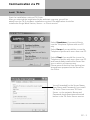
TK-Suite Client
With this Telephone System we included the Software Pack TK-Suite, this contains the CTI
application TK-Suite Client .With this it will be possible to dial telephone numbers direct
from your PC, see calls on your monitor and return calls direct from the missed call list.
The capability can be looked up via the online help by pressing F1 on your PC at any time.
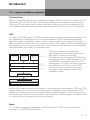
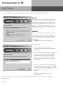
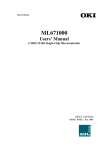
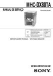
TAPI
Contrary to TK-Suite Client, the TAPI (Telephony Applications Programming Interface) is not
an independent CTI application, but an interface between a TAPI-compatible Windows
application and the telephone system. If the program or applications supports this then it
will be possible to control the entire telephone system. The range of control is depending on
the application you are running. However, in most cases you will be able to set up outgoing
calls and display the arrival of incomming calls.
PC
e.g. database
TAPI
e.g. phonebook
CD-rom
TAPI
e.g. TAPI
telephony
program
TAPI application
TAPI
Microsoft telephony interface
Part of the
Microsoft
operating system
TSPI
Telephony service provider for AGFEO telecommunications systems
CAPI
ISDN card with CAPI driver
AGFEO ISDN telecommunications system
Internal ISDN bus
AGFEO TSP
TAPI is an interface of the Microsoft
operating system at the application end of
Microsoft ’s telephone interface.
A Telephony Service Provider (TSP) from the
manufacturer of the ISDN hardware -in this
case AGFEO –is needed to link this to the
phone system. The TSP is a driver that must
be installed on your PC to run the TAPI
functions and to control the necessary
exchange of data between the PC and
telephone system.
!!
TAPI-compatible system software
Due to the constant increase of functions of these applications that support TAPI the TSP is
always updated. To ensure that the latest version is available to you we provide this TSP
totally free of charge on our Internet home page http://www.agfeo.de . The self-extracting
file contains all the information needed for the installation of this program. Should you have
no internet access, then please contact your Dealer.
Notes
CTI -computer telephony integration via TK-Suite Client or TAPI is only possible with
analogue- or AGFEO System Phones.
E - 11
Introduction
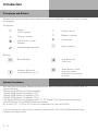
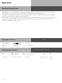
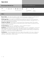
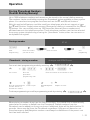
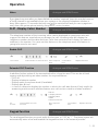
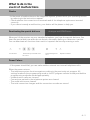
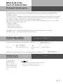
Pictograms and Buttons
All operations and functions ot the telephone system is explained in clear and easy to follow
pictorgrams.
Pictograms
A
h
Z
Q
Ringer
(tone ringing)
Pick up receiver
Dial Phone or Code
Number
Acknowledgement tone
T
ª
K
®
Conduct a call
Replace receiver
Conference
Room monitor
Buttons
r
Recall Button
9
Number Button for
entering digits, e.g. „9“
S
R
Star Button for
functions
Hash Button to dial
extension when
automatic line seizure
is active
System telephones
You may also use System Phones this will aid the ease of operation of your AGFEO ISDN Telephone System.
There are two different models available
-Digital ISDN System Telephone ST 21
-Digital ISDN System Telephone ST 30
-Digital ISDN System Telephone ST 40
The digital ISDN System Telephones ST 21, ST 30 and ST 40 can be connected to any
internal SO bus of the AGFEO Telephone System.
Up to two ST 21, ST 30 or ST 40 can be connected to an internal SO Bus.
In the following the using of your telephone System with a ST 40 and ISDN and analogue
Telephones is described.
E - 12
Introduction
E - 13
Installation
Saftey Notes
- Installation and Maintenance of the System only by trained personnel.
- Important! To prevent personal injury and damage to equipment please ensure that the
system is properly earthed and that the appropriate cable is connected in the mains plug.
- The System must be installed horizontal so that the connection panel is on the right hand
side.
- Do not connect or disconnect any PSTN lines during a thunderstorm.
- Install lines and extensions in such a way that no one walks or trips over them.
- Disconnect the System from the mains supply before opening the connection panel.
Before connection of lines and extensions please ensure that the system is unplugged
from the mains supply. DANGER!
- Preventive measure! Before carrying out any installation work, please touch briefly the
PC/Printer socket of the telephone system. This will discharge any possible electrostatic
charges, thus protecting the telephone system’s electrostatically sensitive components.
- Do not allow liquids to enter the system as short-curcuits may occur.
- No liability will be accepted for consequential damages such as an unintentional
continued connection of a line.
- The telephone system will not operate in case of power failure and you will not be able to
make any type of call.
The AS 35 is indented for the connection to Basic Rate ISDN lines (DSS1, Point to Point, System Access, or Point to Multi Point, Standard Access).
The AS 35 All-in-One can be connected to Basic Rate ISDN lines (DSS1, Point to Point, System Access, or Point to Multi Point, Standard Access) and may also be connected to
analogue exchange lines.
Should you operate the AS 35 All-In-One on an analogue exchange line, then please ensure
that your telephone service provider has meter pulse sending disabled as this may
otherwise interfere with speech quality of a call.
You may connect any equipment which has been approved for the connection to the Public
Switched Telephone Network (PSTN) to the extension port of the system.
Any DSS1 ISDN device which has been approved for the connection to the ISDN telephone
exchange may be connected to the internal SO Bus. In addition you may connect up to two
digital AGFEO System Phones to each SO Bus.
Any other use of the telephone system which is not listed or described is prohibited.
The telephone system has been issued with a universal connection licence.
The system fulfils the specified conformity and safety regulations.
I-2
Installation
Check contents of delivery
1 Telephone System
1 Installation material (3 Wall Plugs S6,3 Wood Screws,Phillips 4x40)
1 Analogue connecting Cable (AS 35 All-In-One only)
2 ISDN connecting Cables (IAE-single wires)
1 RS 232 PC connection Cable
1 USB Connection Cable
1 Template
1 Instructions Pack
1 CD-ROM with TK-Suite and the AIS Konfigurator
The operating instruction in PDF format can be found on our homepage www.agfeo.de
Select Location
Install the System in a dry room free of any hazardous materials. Avoid sites near Air
Conditioners, Radiators, Equipment with excessive high radiation, direct sunlight, excessive
dust and the danger of liquid spillages such as Water or Chemicals.
Ambient Temperature 5C to 30 C. Max humidity 70% non condensing.
The distance of the equipment to other objects such be considered to guarantee an air
circulation. The minimum clearance distance of 50 cm should be adhered to. The distance
of the system to the mains socket and the telephone network socket should not be more
than 1 meter. (Length of mains cable 1.20 m)
It must be made possible to place a Laptop or PC near the telephone system for
programming.
Mains Socket
A separate mains socket for the telephone system should be installed. This will assist to
give uninterrupted service in case that a mains fuse is tripped. The power consumption of
the telephone system is approx 50 VA.
Please ensure that the system cover is replaced before connecting the equipment to the
mains.
Warning! The telephone system must be electrically earthed. Please ensure that the mains
socket is properly earthed before connecting the equipment to it.
I-3
Installation
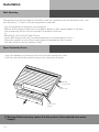
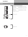
Wall Mounting
The system must be mounted on the wall so that the connectors are at the bottom of it. Use
the mounting 1, 2, and 3 to fix the equipment to the wall.
- Use the template to mark the screw position.
- Before drilling ensure that there is no Mains, Water or Gas supply hidden in the wall.
- Use a masonry drill bit of 6 mm and drill to a depth of 40 mm,
or
- Wood Drill 3.5 mm Drill Depth 35 mm
- Insert Wall Plug and Screw, Screwhead distance from wall approx 3 mm.-- Place the system on top of the screws and pull downwards until in place.
- Use last screw to secure system to wall.
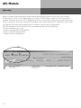
Open Connection Cover
- Use a Screwdriver to press into the cut out of the connection cover.
- Pull the cover from the main housing in the direction of arrow
RS 232
Connection
USB
Connection
Connection
Panel
Before opening ensure that the system is disconnected from mains
! Warning:
supply!
I-4
Installation
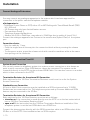
Safety Notes
Please note the following:
- Before the installation or exchange of a module
- Before connection or disconnection of a line
1. Disconnect the System from the Mains Supply.
2. Disconnect all RJ Plugs of all external ISDN Lines either on the Network Termination
Point or the SO Bus
3. With your finger touch the RS232 connection at the underside of the system to discharge
any static electricity and to protect static sensitive components in the telephone system.
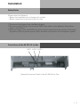
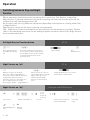
Connections of the AS 281 All-In-One
LED 1 LED 2 LED 3
Opened Connection Panel of the AS 281 All-In-One
I-5
Installation
Connections of the AS 35
LED 1 LED 2 LED 3
Opened Connection Panel of the AS 35
Connections of the AS 35 All-In-One
LED 1 LED 2 LED 3
Opened Connection Panel of the AS 35 All-In-One
LEDs of the AS 281 All-In-One/
AS35 / AS 35 All-In-One
LED 1 (green)
Permanently lit
Flashes
System is operational
System being initialised
LED 2 (red)
LED 3 (red)
I-6
System is connected to the
computer via USB
Data being transferred
via RS 232
Data being transferred
Installation
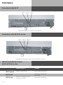
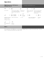
Connections of the AS 281 All-In-One
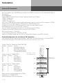
Note with reference to DIP switches:
a8
b8
a7
b7
a6
b6
a5
b5
a4
b4
a3
b3
a2
b2
a1
b1
The DIP switch settings for the SO Busses are as follows:
Towards PCB:
Switchable SO Bus is set to internal
Away from PCB:
Switchable SO Bus is set to external
The DIP switch settings for the termination resistors are as
follows:
Towards PCB:
Termination Resistor is set to ON
Away from PCB:
Termination Resistor is set to OFF
analogue extensions
switchable S0s
INT/EXT
100R
S0/1
INT/
EXT
INT: EXT:
a2 a1
b2 b1
a1 a2
b1 b2
Analog Ämter
Amt 2
Amt 1
La2
Lb2
La1
Lb1
analogue lines
I-7
Installation
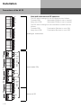
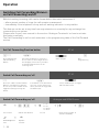
Connections of the AS 35
Note with reference to DIP switches:
a12
b12
a11
b11
a10
b10
a9
b9
The DIP switch settings for the SO Busses are as follows:
Towards PCB:
Switchable SO Bus is set to internal
Away from PCB:
Switchable SO Bus is set to external
The DIP switch settings for the termination resistors are as
follows:
Towards PCB:
Termination Resistor is set to ON
Away from PCB:
Termination Resistor is set to OFF
a8
b8
a7
b7
a6
b6
a5
b5
analogue extensions
a4
b4
a3
b3
a2
b2
a1
b1
INT/EXT
S0/4
INT/
EXT
S0/3
INT/
EXT
100R
INT:
a2
b2
a1
b1
a2
b2
a1
b1
EXT:
a1
b1
a2
b2
a1
b1
a2
b2
switchable S0s
100R
INT/EXT
INT/EXT
S0/2
INT/
EXT
S0/1
EXT
100R
INT:
a2
b2
a1
b1
a2
b2
a1
b1
EXT:
a1
b1
a2
b2
external S0
100R
frei
I-8
Installation
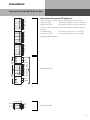
Connections of the AS 35 All-In-One
a12
b12
a11
b11
a10
b10
a9
b9
a8
b8
a7
b7
a6
b6
a5
b5
Note with reference to DIP switches:
The DIP switch settings for the SO Busses are as follows:
Towards PCB:
Switchable SO Bus is set to internal
Away from PCB:
Switchable SO Bus is set to external
The DIP switch settings for the termination resistors are as
follows:
Towards PCB:
Termination Resistor is set to ON
Away from PCB:
Termination Resistor is set to OFF
analogue Extensions
a4
b4
a3
b3
a2
b2
a1
b1
INT/EXT
100R
S0/2
INT/
EXT
INT: EXT:
a2 a1
b2 b1
a1 a2
b1 b2
a2 a1
b2 b1
a1 a2
b1 b2
INT: EXT:
S0/1
INT/
EXT
switchable S0s
100R
INT/EXT
Analog Ämter
Amt 2
Amt 1
La2
Lb2
La1
Lb1
analogue lines
I-9
Installation
Connect Analogue Extensions
You may connect any analogue apparatus to the system which has been approved for
connection to the public switched telephone network.
a/b-Apparatus is:
- Telephone (2 wire Phone or POT) either LD or MF Dialling with Timed Break Recall (TBR)
(60 – 800 ms)
- LD Phones may only have limited feature access.
- Fax machines Group 3
- Telephone Answering Machines
- Modem 56k (V.90 to 56600 bps, may reduce to 33600 bps due to quality of lines V.34+)
Connect the analogue apparatus via 2 wires to the a and b wire (Speech Pair) of the system
port
Connection of wire
- Strip the cable by 11 mm.
- Push the single wire all the way into the connection block without pressing the release
catch.
- To disconnect a wire, press the release catch with a small screwdriver while at the same
time pulling out the conductor
External S0-Connection Fixed S0
System Access Connection
You can only connect a telephone system to a system access connection or also known as
point to point connection. Other ISDN devices cannot be connected. The system can be
connected directly to the NTTP via the enclosed ISDN Cable. You can also connect to a socket
which is then connected to the NTTP.
Termination Resistors for the external SO Connection
Both switches for the 100 Ohm Termination Resistors must be set to on for the System
Access Connection.
Standard Access Connection
A Point to Multi Point connection may be installed as a SO Bus type and up to 12 ISDN
Sockets can be connected to this. The telephone system and up to seven additional ISDN
devices may be connected to the SO Bus.
Termination Resistors for the external SO Connection
Both switches for the 100 Ohm Resistors must be set as follows:- closed or on if the connection is made directly onto the NTTP or on the last socket which
has no 100 Ohm Termination Resistors fitted.
- open or off if the last socket has the 100 Ohm Termination Resistors installed or if the
telephone system is not the last ISDN device on a PTMP line.
Connect the phone system directly with the ISDN connection cable to an ISDN socket of the
SO Bus or to the NTTP if the installation has no SO Bus option.
I - 10
Installation
Switchable SO Connections
(internal or external S0-Connection)
External S0-Connection
You may connect the external SO Connection to a System Access (PTP) or Standard Access
(PTPM) line. Please refer to External SO Connection (RJ45 Socket).
Use the enclosed ISDN Cable and connect the four wires to the SO connection block of the
module.
- Push the wire all the way into the connection block without pressing the release catch.
- Connector: a1 -green
b1 -brown
a2 -yellow
b2 -white
- To disconnect a wire, press the release catch with a small screwdriver while at the same
time pulling out the conductor.
- Guide the cable through the cable comb.
Termination Resistors for the external SO Connection
System Access (PTP) –Both DIP Switches (Page 1-7/8) for the 100 Ohm Resistors must be
closed or set to on. (Default Setting)
Standard Access (PTMP) - Both DIP Switches (Page 1-7/8) must be
- closed or set to on if the connection is made directly onto the NTTP or on the last socket
which has no 100 Ohm Termination Resistors fitted.
- open or set to off if the last socket has the 100 Ohm Termination Resistors installed or if
the telephone system is not the last ISDN device on a PTMP line.
Plug the ISDN Plug into the ISDN connection after completion of all installation work.
I - 11
Installation
Internal S0-Connection
You can connect up to 8 ISDN devices like on a PTMP connection on the internal SO Bus of
the System.
ISDN Apparatus:
Digital AGFEO System Phones (max 2 digital phones per SO Bus)
-ISDN -Telephones
-ISDN -PC-Cards
-ISDN –Fax machines
Up to four ISDN devices without additional power may be connected. For example: 4 ISDN
Telephones or 2 Digital System Phones plus 2 ISDN Telephones.
Connections of further ISDN devices will need their own power source.
ISDN Apparatus must use the DSS1 protocol.
You will need the following material to install an internal SO Bus.
Telephone wire CW1308 (minimum 2 pair) or CAT5 Cable
RJ45 Sockets max. 12 per Bus
2 Termination Resistors, 100 Ohm 0.25 W
Maximum SO Bus length will be 130 m. (Telephone System to last RJ45 Socket)
Termination Resistors for the Internal SO Connection
The internal SO Bus must be terminated. Install two 100 Ohm Resistors in the last RJ45
Socket (See Diagram). Both DIP Switches must be closed (or set to on)
Colour Code for Telephone Cable CW1308
SO Bus Contact Colour
a1
4
Blue/white Bands
b1
5
White/Blue Bands
a2
3
White/Orange Bands
b2
6
Orange/White Bands
Colour Code for T568B (CAT5)
SO Bus Contact Colour
a1
4
Blue/White
b1
5
White/Blue
a2
3
White/Green
b2
6
Green/White
Colour Code for T568 A (ISDN)
SO Bus Contact Colour
a1
4
Blue/white
b1
5
White/Blue
a2
3
White/Orange
b2
6
Orange/White
Most common used standard for SO Bus
installation is T568B (CAT5)
Ensure that pairs are not mixed up.
I - 12
S 0- internal
b1
a1
b2
First Pair:
a1, b1
Second Pair: a2, b2
a2
UAE
1 2 3 4 5 6 7 8
UAE
1 2 3 4 5 6 7 8
UAE
1 2 3 4 5 6 7 8
UAE
1 2 3 4 5 6 7 8
100 Ω
100 Ω
Max distance
S0 Bus: 130 m
Installation
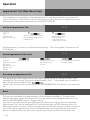
Connect the AS 281 All-in-one/
AS 35 All-In-One to an analogue
exchange line
- Connect each wire of the line cord to the relevant port of the AS 281 All-In-One /
AS 35 All-In-One.
- Connect the plug to the socket of your telephone provider.
Please note that in difference to the ISDN line the analogue exchange line is unable to send
call progression. As such the calling party will not receive a confirmation from the
telephone network if the called party has answered. Therefore there will be the following
difference between analogue - and ISDN line.
- From the time the exchange line has been seized by the relevant extension will be the
time the call will be logged as to have started, even if the called party is busy or does not
answer.
- MF overdialling is possible but will not be recognised by the system as such. This will
result that the dialled telephone number including overdialled number will be stored in
the call log and last number redial.
I - 13
Installation
Door Phone
It is possible to connect a door phone to the extension port of the telephone system. This
analogue door phone will receive the control signals as DTMF tones. To use such a door
phone you must set the relevant extension port to door using TK Suite, section “System
Telephones”, drop down menu “Phone Type”.
In addition you must assign an extension number for the relevant bell push buttons. This
setting you will find under “Doors”. Up to 4 Bell Push Buttons are supported for one door
phone. After this you would have to set the relevant DTMF digits to operate the door phone,
these you will find in the user manual of the door phone.
I - 14
Installation
Commissioning
You have installed the system. However, before you can make a call you must do the
following:
- Connect the extensions. You may connect any apparatus which you are allowed to
connect to the public switched telephone network.
- Connect the RJ 45 plug to the ISDN network or connect the relevant connection cable to
the analogue network. (Analogue Network AS 35 All-In-One only)
- Switch on the telephone system by plugging the mains plug into the mains socket.
Programming to the users requirement can be carried out via the connection of a PC. The
remote programming of the system may be carried out via your dealer.
Notes
To avoid calling wrong telephone numbers please ensure that the following is carried out.
After installation of the system please dial from an analogue MF telephone a single digit,
this ensures that the system recognises the correct dialling method for the relevant
extension. Should you change to a telephone which is dialling in LD, then you must dial a
digit higher then 2. Should you operate two telephone on one port, then you must ensure
that both phones connected are of the same dialling method.
I - 15
Installation
Default Settings
Listed below are the default settings:
AS 35
- The Termination for external S0 Connection is closed, the 100 Ohm terminating resistor
is switched on
- Switchable S0 connection S0-2: set to external, the 100 Ohm terminating resistors are on
- Switchable S0 connections S0-3 and S0-4: set to internal, the 100 Ohm terminating
resistors are on
AS 281 All-In-One and AS 35 All-In-One
- Switchable S0 connections S0-1 and S0-2: set to internal, the 100 Ohm terminating
resistors are on
Both Systems
Extensions: 11, 12, 13, 14, 15, 16, 17, 18, 19, 20
All users set to: Telephone
External line access: unrestricted for all extensions
Line access with 9
Day Service 1 no entry
Night Service 2 no entry
Call diversion internal: off
Do not Disturb: Off for all extensions
Call waiting: off for all extensions
transmission of own number to called and calling party: set to on
Music on Hold: Internal off
Automatic dialling: off
Printing of call records: off for all extensions
Printing of dialled phone number: without
Cost limit: No entry
Charge unit factor: 0,061
Base factor: 0,061
Disconnect on Cost limit: off
Program access code: off
Switchbox number: no entry
Busy on Busy: off
Prefix 0 to call from call log via internals SO connection: off
System Phones:
-Display Call Charges:off
-Display:english
-Call Log:off
-Pop Up Menu : on
I - 16
Installation
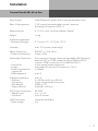
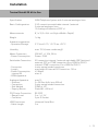
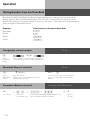
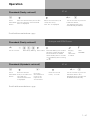
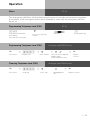
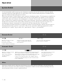
Tecnical Data AS 281 All-In-One
Specification
ISDN Telephone System with 2 external analogue lines
Basic Confioguration
1 SO connections switchable internal / external
8 Analogue Extensions (POT’s)
Measurements
8,1 x 32,2 x 24,4 cm (High x Width x Depth)
Weight
1,6 kg
Ambient temperature
- Operation/Storage
5 °C bis 40 °C / -25 °C bis +70 °C
Humidity
max. 70 % (none condensing))
Mains Connection
- Power Consumption
230 VAC, +/-10%, 50 Hz
Pmax = 35 W
Switchable Connection
SO connection internal / external switchable (DIP Switches)
external: PTP or PTMP connection Euro ISDN 2e (DSS1)
internal: PTMP connection, Euro ISDN 2e (DSS1)
4 wire spring loaded connectors
max lenght of internal SO Connection: 130 m
4,5 Watts
- Connection
- Length
- Power Consumption
internal S0
- ISDN-Apparatus
max. 8
Analogue Apparatus
- Distance
- Connection
- Dial Method
- Enquiry Button
max. 8
2 x 50 Ohm (ø 0,6 mm, 800 m)
2 wire spring loaded connectors
DTMF or LD
Flash (80 - 600 ms)
PC/ Printer Connection
- Range/ Level
- Connector
RS 232C
3 m / +/- 5 V
9 pin D-Socket
USB Connection
- Cable Length
Universal Serial Bus
3m
I - 17
Installation
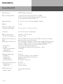
Tecnical Data AS 35
Specification
ISDN Telephone System
Basic Confioguration
1 external So Connection (PTP or PTMP)
3 SO connections switchable internal / external
12 Analogue Extensions (POT’s)
Measurements
8,1 x 32,2 x 24,4 cm (High x Width x Depth)
Weight
1,6 kg
Ambient temperature
- Operation/Storage
5 °C to 40 °C / -25 °C to +70 °C
Humidity
max. 70 % (none condensing)
Mains Connection
- Power Consumption
230 VAC, +/-10%, 50 Hz
Pmax = 35 W
External S0 Connection
fixed
Switchable Connection
PTP or PTMP connections, Euro ISDN 2e via RJ 45 Socket
and enclosed connection cable
SO connection internal / external switchable (DIP Switches)
external: PTP or PTMP connection Euro ISDN 2e (DSS1)
internal: PTMP connection, Euro ISDN 2e (DSS1)
4 wire spring loaded connectors
max lenght of internal SO Connection: 130 m
4,5 Watts
- Connection
- Length
- Power Consumption
internal S0
- ISDN-Apparatus
max. 8
Analogue Apparatus
- Distance
- Connection
- Dial Method
- Enquiry Button
max. 12
2 x 50 Ohm (diam. 0,6 mm, 800 m)
2 wire spring loaded connectors
DTMF or LD
Flash (80 - 600 ms).
PC/ Printer Connection
- Range/ Level
- Connector
RS 232C
3 m / +/- 5 V
9 pin D-Socket
USB Connection
- Cable Length
Universal Serial Bus
3m
I - 18
Installation
Tecnical Data AS 35 All-In-One
Specification
ISDN Telephone System with 2 external analogue lines
Basic Confioguration
2 SO connections switchable internal / external
2 external analogue lines
12 Analogue Extensions (POT’s)
Measurements
8,1 x 32,2 x 24,4 cm (High x Width x Depth)
Weight
1,6 kg
Ambient temperature
- Operation/Storage
5 °C bis 40 °C / -25 °C bis +70 °C
Humidity
max. 70 % (none condensing))
Mains Connection
- Power Consumption
230 VAC, +/-10%, 50 Hz
Pmax = 35 W
Switchable Connection
SO connection internal / external switchable (DIP Switches)
external: PTP or PTMP connection Euro ISDN 2e (DSS1)
internal: PTMP connection, Euro ISDN 2e (DSS1)
4 wire spring loaded connectors
max lenght of internal SO Connection: 130 m
4,5 Watts
max. 8
- Connection
- Length
- Power Consumption
internal S0
- ISDN-Apparatus
Analogue Apparatus
- Distance
- Connection
- Dial Method
- Enquiry Button
max.12
2 x 50 Ohm (ø 0,6 mm, 800 m)
2 wire spring loaded connectors
DTMF or LD
Flash (80 - 600 ms)
PC/ Printer Connection
- Range/ Level
- Connector
RS 232C
3 m / +/- 5 V
9 pin D-Socket
USB Connection
- Cable Length
Universal Serial Bus
3m
I - 19
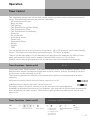
Operation
ST 40
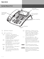
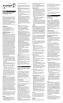
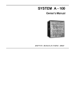
System Phone ST 40
Softkeys
Adjustable
Graphic Display
Loudspeaker
underneath
handset
10 Function Buttons and LED's
Mak
eln 1
Firm
Geb
a
Mak
üh
eln 2
Nac ren
IHK
Anruf ht
sc
HdR
E. Pa hutz
Konf
schk
eren
e
D
ur
z
J. Flie
Sven chsage
ge
Umle
ja Ya
ra
Term
Vers itung zu
iche
ine
rung
T.Chr
Bank
is
Intern tian
Anw
alt
AB
1
-
2
GHI
+
4
PQ
7
TU
8
Button Labelling
C
DE
3
JKL
5
F
MNO
RS
6
V
WX
YZ
9
0
Microphone
1 0 Numeric Keypad
M
Mail Button - Flashes on new
entry in call log or missed calls.
Stays lit for numbers already
viewed. Clears when number is
called or deleted from list by
pressing clear button
%
10 function Buttons - User
programmable, two entries per
Button (First & Second Level)
Keep this button pressed for
approx 1 sec. to show the second
level. LED indication only for first
level.
* # * and # Buttons
! Set Button - Start and end
programming. Keep this button
pressed to toggel between
programming tree and
programming index
=
y&
Handsfree Button - Activates the
Loudspeaker. Button lights up
when activated.
Arrow Buttons - To scroll through
the display where there is more
than one function.
t
Phone Book Button - Retrieval of
Telephone Numbers.
:
LNR - Last Number Redial Button. Keep this button pressed to
show call log.
1-2
-
+
Plus and minus for volume
control of handset and speaker.
Softkeys: The function for these
buttons are shown in the display
above. Function offered are
depending on the relevant phone
status.
Operation
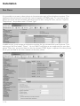
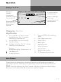
Display of the ST 40
Display in
standby:
Internal and
external S0 Status,
one box per S0.
WK26
ST 40
Tu 11.Jul.06
11:59
*${}%“S
ii xx A
Status of analogue
trunk lines
12 14 16 18
Extensions off hook.
Called extension
will be shown
inverted.
Activated features
are shown here
Current function of
soft key below.
ok
back
1. Display Line: Date / Time
Index of functions:
External ISDN-Line. One line (a Bchannel)is busy. The "x" is shown
inverted on an external call.
$
Diversion/ISDN-call forwarding
active
{
CVA 2 (Night service) on
i
Internal ISDN-Line. One Line (a Bchannel) is busy.
Phone lock on
A
Analogue trunk line. The "A" is shown
inverted on an external call
}
%
"
S
Sensor activated
F
Filter ativated
I
Withhold own number
PC
PC Programming in process
x
Features:
Browse with yx, Confirm with „ok“
Call-Waiting off
*
Wake-up on
Appointment on
Do Not Disturb on
Menu Guidance
Please look at the display when using the telephone as it will guide you through all
operating procedures. Depending on its operating condition the following soft keys are
offered:
Answer, Park Call, Retrieve, Get, Split, Transfer, Call Back. Conference, Recall, Reject,
Disconnect, Go To, Back, End, OK, on, off, Store and Door Opener.
1-3
Operation
Notes on using this Manual
ST 40
The highlighted bar above each instruction will indicate if the setting procedure is for the ST
40, Analogue- or ISDN telephone.
The soft keys below the phone display will be indicated by this symbol.
The relevant button which is to be pressed will be shown in black.
Please observe the display area if no black button is indicated. Should there be more than
three option, then the most used function will be shown first. More functions can be
selected by pressing the arrow buttons.
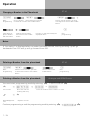
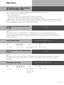
System Telephones - Settings
You can alter the following settings on your System Phone:
-Tone Ringer - Volume and Pitch
-On Hook / Handsfree Volume
-Handsfree microphone – Automatic activation on Voice Alert
-Headset and Handset Volume
-Telephone Lock – Your Phone will be barred from making calls
-Display of call charges
-Status display (Extensions and Lines) and or Date & Time
-Set Call Log
-Set access to outside line -direct or with access digit
Setting of Date & Time is done by the ISDN Network (Not available from UK Network
Providers)
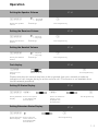
Setting the Ringing volume
!21
ST 40
z 1 -very low
!
7 -very high
Alter the Ringing
Volume
Enter digit
Exit Programming
Your phone will ring at the newly set value.
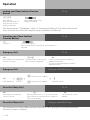
ST 40
Setting the Ringers Pitch
!22
Setting the Ringers
Pitch
z 1 - Tone 1
!
7 - Tone 7
Enter digit
Exit Programming
Your Phone will now ring with the selected pitch.
1-4
Operation
Setting the Speaker Volume
!251
z 1 - very high
ST 40
!
7 - very low
Setting the speaker
volume
Enter digit
Exit Programming
ST 40
Setting the Receiver Volume
!252
z 1 -very low
!
7 -very high
Setting the Receiver
Volume
Enter digit
Exit Programming
ST 40
ST 40
Setting the Headset Volume
!253
z 1 -very low
!
7 -very high
Setting the Headset
Volume
Enter digit
Exit Programming
ST 40
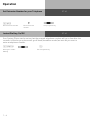
Cost display
!28
Setting of cost
Display
!
Switch on or off
Exit Programming
Please note that this service may have to be requested from your network provider as
indication of call charges during or at the end of a call. (This service is not available from
the UK network providers)
Setting S0 Status Display
!291 y&
Setting S0 Status Select a free space
in the display with
Display
arrow buttons
ST 40
y&
!
Select the S0 whose
status is to be
displayed with
arrow buttons
Setting Extension Status Display
!292 z
Setting Extension Select extension
Status Display
whose status is to
be displayed with
arrow buttons
Exit Programming
ST 40
!
Exit Programming
1-5
Operation
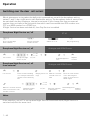
Set Extension Number for your Telephone
z
!91
Set Extension Number
ST 40
Enter Extension
number
exit programming
ST 40
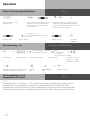
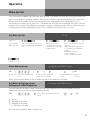
Instant Dialling On/Off
Your System Phone can be set so that the entered telephone number will go to line after the
receiver is lifted or your phone will go off hook (handsfree mode) as soon as you start to
enter a telephone number.
!2#2
Setting for Instant
Dialling
1-6
!
Exit Programming
Operation
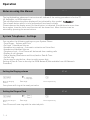
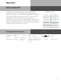
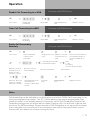
Button Assignment
ST 40
On delivery of the Phone System all programmable
function Buttons of the Phones have a default setting
which are the same on all System Telephones. These Buttons can be individual programmed to suit your specific
needs. Each of the 10 Buttons can have a function
allocated to it, which you can activate by just pressing the
Button. In addition each of the function Buttons have a second level. To activate the second level you must hold the
function Button pressed for 1 second.
Changing Button Assignment
!31 ( z )
Start
Enter PIN if
Programming prompted
%
Press Button,
you want to
assign
Default Setting:
Announce
System Memory
Call Waiting
System Memory
Appointment
System Memory
Tone Call
System Memory
Call Filter
System Memory
Mute
System Memory
System Memory
System Memory
Diversion to
System Memory
System Memory
System Memory
Internal
System Memory
ST 40
z
y&
Enter the first letter of the
function ´s name,or choose
the function with arrow
buttons
!
Confirm
selection
End
Programming
1-7
Operation
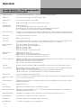
Function Buttons - Freely programmable
Function Buttons (overview)
ST 40
TAM activation
To switch TAM module on or off of the ST 30 System Phone.
TAM info
To listen to messages recorded on the TAM.
TAM Memo
To record messages on the TAM
Reject
Reject the ringing call. Caller will hear busy tone.
Call Waiting
Enabled / off
You can select if:
If the caller will get busy tone if on a call. (off)
If a waiting call should only be visually indicated on your phone.
Or if a call waiting tone should be signalled. (audible)
Call Deflection
To divert an incoming call during the ringing phase. There will be no change to the
ringing tone when diverted. The caller will not be aware that the call was forwarded.
Call Filter
To switch Call Filters on or off.
Call Log
Will list the Call Log
Cleaning
In connection with the check in / check out button. This can be used to signal to the
front desk that a room has been cleaned and is ready for occupation.
Do not Disturb
(DND)
This will disable the Tone Ringer
Special function buttons may be set:
DND for internal calls
DND for external calls
DND for internal- and external calls.
Night Service
(AVA 2)
Night Service on or off.
Special function buttons may be set:
Night Service can be switched for each trunk line.
Night Service can be switched for all trunk lines.
Call Forwarding
Enable / Disable Call Forward if designated extension does not answer on incoming call.
Special function buttons may be allocated:
Switch Call Forward for each trunk line.
Switch Call Forward for all trunk lines.
Tannoy
Announcement via Public Address Amplifier connected to the Telephone System
Busy on Busy
Return Busy Tone to Caller if one Extension is Busy within Call Distribution Group.
Special Buttons can be assigned
-Busy on Busy for each Call Distribution Group swithcable seperately
-Busy on Busy for call Call Distribution Group switchable together
Call by Call
To select Network Provider via LCR
Check In/ Check
Out
Check in / Check out for Hotel applications. Will start and stop call logging and switch
on or off trunk line access.
Page (Tannoy)
Pageing Announcement to System Phones. Programmable function Button - Page
specific Extensions.
Units
Display Call Cost
Call Capture
Malicious Call Identification via ISDN-Exchange
Remote functions
Sending of stored DTMF Tones (1..0 * #) for a remote interogation of a Telephone
Answering Machine (TAM)
Remote Answer
Possible to make the ringing extension go off hook from another phone.
Group Button
Log in and out of Groups and their features
Headset
To use a Headset (only Digital System Phones)
Mute Button
To mute microphone on your telehpone.
1-8
Operation
Function Buttons - Freely
programmable Function Buttons
(overview)
ST 40
Call Pick Up
To Pick Up incoming calls. Special Function Button can be assigned to Pick Up internal
and external calls from specific extensions.
Withhold
To withhold own number to be sent to a called party.
Internal Button To Dial Extensions. Special function Button programmable: Call specific Extension
ISDN-Hold
To Hold an external call in the Telephone Exchange (only available on PTMP
connection)
ISDN-Call
Forwarding
To switch on or off the ISDN Call Fowarding feature.
Conference
To set up a Coneference Call with Internal and or External calls.
Speaker Volume To set the Speaker Volume Level for Handsfree or On Hook use.
LCR
To switch Least Cost Routing (LCR) on or off for your System Phone.
Call Split
To talk to more then one External Call in turn. (Switch between them)
Brokers Call
To talk to one internal and one external call at a time and without connecting them.
External
To transmit another of your MSN numbers other the the one allocated to the Extension
making the call. A special Button can be assigned for this feature.
Relays
To switch a Relays. A special function Button can be assigned.
Reserve
To reserve a line should all lines be engaged at the time.
Sensor
To Enable or Disable Sensors.
SMS info
Will list all saved SMS messages
Write SMS
Message
To write new SMS message.
Enquiry Call
To establish or set up an Enquiry Call, a connection or a Brokers Call
Telephone Book To select a number out of the System Telephone Book
Telephone Lock To Lock the System Phone and activate pr-set Emergency and Direct Call numbers.
Appointment
To set or cancel a preset Appointment Time
Timer
To switch on or off a Time based function, such as Day-Night Service, Call Forwarding,
Relays etc. Button can be assigned for this function. 10 Timers are available. Timers
are form 0 to 9.
Doorphone and Function Button can be assigned to connect to the Doorphone. Another Button can be
Lock Release assigned to activate Lock Release.
Transfer
To transfer and connect an external call to an external call.
Diversion from To divert all calls from another phone to the current phone used.
(Follow me)
Diversion to
To divert all calls to another extension- or external number.
Wake Up
To Enable or Disable the set Wake up call..
Destination
Button
- Public
- Private
To Call a preset Telephone Number
- This number is stored in the Telephone System Memory
- This number is only stored in your telephone
1-9
Operation
ST 40
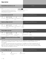
External Line Access
Depending on your preference the system offers different modes to connect to an outside
line. Direct access will connect any number dialled to the exchange line.
To dial an extension you prefix the extension number with #. If your phone has no # button
then you are unable to make any internal calls.
If you select the setting with access digit then you have to dial 0 (or 9) to get an outside line. In
this case you would dial 9 and the required telephone number or the two digit extension
number to make an internal call.
ST 40
Setting direct access
!2#1
Setting direct
access
!
activate or
desactivate
exit programming
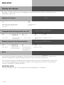
Analogue and ISDN Phones
Setting external Seizure
+
P S 51
PZ 0 = direct access off
Q P -
1 = direct access on
Lift recever
1 - 10
Setting external Seizure
Set variant
Acknowledgement Replace
tone
receiver
Operation
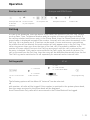
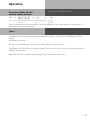
Making a Call
ST 40
To make an internal call, pick up receiver and dial the extension number. Please contact
your Telephone System Manager for an Internal Telephone Directory.
To make an exchange line call depends on how your telephone system is programmed.
For users who’s extension is set to ‚Direct Access‘ just need to dial the the required
telephone number. If you would like to make a call to another extension on your telephone
system, then please prefix the extension number by #.
If a line access digit is set then you have to dial 0 (or 9 as the case may be) to get an outside
line and then dial the telephone number required. If you would like to call another extension
on your system, then just dial the two digit extension number.
If Call Forwarding is active on your line, then you will hear a special dial tone from the
telephone exchange after you connect to the line. This will remind you that this or another
feature may be set in the exchange
1 - 11
Operation
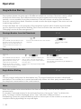
"Direct Access" activated
Calling an internal user:
ST 40
+
#z
Lift receiver
Press the ‘Internal or Intercom’ Button
and dial the required extension number.
Calling an external number:
+
z
Lift receiver
Just dial the telephone number required. The telephone
system automatically seizes an outside line .
Analogue and ISDN Phones
"Direct Access" activated
Calling an internal user:
+
Lift receiver
Calling an external number:
#z
Press the ‘Internal or Intercom’ Button
and dial the required extension number.
+
z
Lift receiver
Just dial the telephone number required. The telephone
system automatically seizes an outside line.
ST 40
"Direct Access" deactivated
Calling an internal user:
+
Lift receiver
Calling an external number:
z
Dial the Extension
Number only
+
0z
Lift receiver
Dial 0 (or 9 if applicable) to get a line. On hearing external dial
tone dial required telephone number
Analogue and ISDN Phones
"Direct Access" deactivated
Calling an internal user:
+
Lift receiver
z
Dial the Extension
Number only
Calling an external number:
+
0z
Lift receiver
Dial 0 (or 9 if applicable) to get a line. On hearing
external dial tone dial required telephone number
1 - 12
Operation
External Access with specific
MSN
ST 40
You may send another MSN number other then the one allocated to you to the network.
External Access with
External Button
%
Press Button
External
ST 40
z+
y&
Select the phone number
or name of the line you wish to
access.
Dial the required telephone
number
External Access with
specific External Button
+
Lift
receiver
ST 40
z
%
You now will hear external dial
tone and
can dial the number required.
Press the MSN /external Button to seize an outside line.
Line name and number may be
displayed.
External Acces with specific MSN
+
Lift receiver
Analogue and ISDN Phones
P S 0 0 P Z
prepare external
dialling
P R P Z
enter specific
MSN
terminate
entry
enter external
phone number
P T
conduct
call
Reserving an Outside Line
On requesting an outside line you will hear busy tone if all lines are engaged. You may now
request for a line to be resevered. As soon as an outside line becomes free the system will
phone you back. When picking up the receiver you will hear external dial tone and can dial
your number.
Reserving an Outside Line
ST 40
On hearing busy tone while dialling number replace
press the left Button to reserve an outside receiver
line.
R
The Telephone System
will call you back as
soon as a line
becomes available.
+
z
Pick up ReceiDial required
ver, you will hear number
external dial
tone
1 - 13
Operation
Reserving an Outside Line
+
Lift receiver
Analogue and ISDN
ST 40
Phones
P 0 Q P r S 2 9
reserve outside line
Q
P -
acknowledgement
tone
replace
receiver
Notes
Barred Calls – You will not be able to make calls for which your extension is call barred. If
you try and make a call to a barred number, error tone will be returned to you.
DTMF signalling -Is possible to send DTFM Tones during a connection. This can also be
done during an enquiry call, Brokers Call and Three Party Conference. Any digit from 0 – 9
including * and # can be transmitted.
Prepare for dialling -The receiver is on the hook. Enter the phone number.The number
entered is displayed. The call will be connected as soon as the receiver is picked up or the
handsfree button is pressed.
On Hook Dialling-Press the “loudspeaker ” button and dial the phone
number.Lift the receiver once the other party answers.
Handsfree -Instead of lifting the receiver, you can also press the “loudspeaker ”button and
have a handsfree telephone conversation. Handsfree mode is turned off when you pick up
the receiver. To switch to handsfree again press the speaker button before you replace the
handset. To end the call press the speaker button.
Call Monitor – Press the speaker button if you want other people in the room to hear your
telephone conversation. People in the room can listen to the other party via the speaker
while you continue your call as normal.
1 - 14
Operation
Accepting Incoming Calls
ST 40
Due to a different ringing you are able to differentiate between extension -,
incoming and doorphone calls. You can also see who is phoning you before you answer the
call.
ST 40
You are called
A
P +
P A
lift receiver
conduct the call
Analogue and ISDN Phones
You are called
A
P +
P A
lift receiver
conduct the call
Call Waiting
ST 40
You can receive a second call while already on a call. If this happens you will hear a
Call Waiting tone in your receiver. You can accept or reject the waiting call.
ST 40
Call Waiting
1. Possibility:
T Q P You are on a call
and hear the call
waiting tone
Replace the
receiver to end the
current call.
A
P +
Your telephone will
ring for you to
answer the waiting
call.
Lift Receiver
P A
Conduct Call
2. Possibility:
%
Press the Split Button.The first call is placed on hold while the waiting one is connected to you. You can alter between
the calls by pressing the Split Button. You can also deflect the waiting call.
1 - 15
Operation
Call waiting
Analogue and ISDN
ST 40
Phones
1. Possibility:
A Q P
-
A
P
You are on a call
and hear the call
waiting tone
End the call
Automatic ringing
by the waiting
party
+
P
Lift the receiver
A
Conduct the call
2. Possibility:
A Q P r
You are on a call
and hear the call
waiting tone
P 0
Press R the call is
placed on hold
P
Answer the waiting
call
A
conduct the call
Reject the waiting call
ST 40
A
%
Press the Reject Button. The caller will now hear
busy tone if you are the only phone programmed
to ring on an incoming call. If there are also other
phones programmed to ring on an incoming call
then the caller continues to hear the ringing tone.
Reject the waiting call
A Q P r
You are on a call
and hear the call
waiting tone
Press R the
call is placed
on hold
Continue your original call.
Analogue and ISDN Phones
P S 21
Reject the waiting
call
P A
Continue your call
Notes
If you hear error tone when trying to answer a waiting call, then the call waiting tone
is for the other party.
The call waiting tone can be switched off by setting ‚Call waiting deny
1 - 16
Operation
Call Transfer
ST 40
You can transfer an incoming call to an extension or another external number. When
transferring a call to an extension you can announce the caller before replacing the
receiver.
Internal Transfer with announcement
ST 40
z
A
If you are on an external
call and would like to
transfer this to an
extension
A
press "Enquiry" and dial the
required extensions
-
The extension answers, announce the call
and replace the receiver.
If the extension does not answer, press "back" to get back to th external call.
You may transfer the call to another extension.
Internal Transfer with announcement
A
P r
Conduct external
call
P Z
enquiry, external
call is placed on
hold
Analogue and ISDN Phones
P A
Enter internal
phone number
Internal Transfer without
announcement
A
If you are on an external
call and would like to
transfer this to an
extension
P -
Announce
external call
transfer external
call
ST 40
z
press "Enquiry" and dial the
required extensions
The called extension is connected to the
transferred call as soon as the receiver is
picked up.
The call will also be returned to you if the extension has not answered the call within 45
seconds. Ringing of your extension will be cancelled if you fail to answer the returned call
within 60 seconds.
1 - 17
Operation
Internal Transfer without announcement
Analogue and ISDN
ST 40
Phones
A
P
P r
Conduct external
call
P
enquiry, external is
placed on hold
Z
transfer external call
Enter internal
phone number
ST 40
External Transfer
% z
A
You are on a call to
an external number
and would like to
transfer this call to
another external
number.
A
-
While speaking to the caller press the
SPLIT or BROKERS CALL Button (The
external call is put on hold and if so
programmed will hear Music on Hold),
dial the required telephone number and
talk to the new party.
Press the middle
button
If the called Party does not answer, press
hold.
to get back to the call placed on
Analogue and ISDN Phones
External Transfer
A
P r
Conduct first external call
Transfer first external call
P 0
enquiry, external
call is placed on
hold
r S 20
replace receiver
P Z
Seize outside line
P A
Enter external
phone number
P
Conduct second
external call
P Replace the
receiver
Notes
When transferring an external call, you must always seize the outside line by entering „9“,
even if spontaneous outside line seizure with internal is set on the telephone.
External Transfer is only possible if a dial-up line (B-channel) is free.
You bear the cost of the externally transfered call.
A user on the internal S0 bus can only forward an external call internally if the second B
channel of the internal S0 bus is free. External/external Transfer is not possible.
1 - 18
Operation
ST 40
Transfer an Outside Line
You can give an extension an outside line. This is useful in cases were the extension
is not allowed to make outside calls. The extension can phone the system operator
who can tranfer a line. Note you will transfer a line with your Class of Service.
ST 40
Transfer an Outside Line
A
-
%
Extension calls you and asked
for an outside line.
Press the Brokers Call Button or
the Split Button
Press "transfer".
The calling extension can now
make an outside call.
Call Waiting/ Callback when free
A extension already on a call will hear a call waiting tone in their handset when you call it. If
the called extension replaces the receiver then the waiting call will ring immediately at this
extension. You can initiate Call Back when Free if the called extension does not accept your
call.
Requesting Ring back when free
ST 40
A
-
On hearing the busy tone
when calling an extension.
Press Softkey "RecalL". Ring
back when free is initated
Requesting Ring back when free
+
Lift receiver
P Z
dial internal
number
Q
busy tone
Replace Receiver
Analogue and ISDN Phones
P r
Enquiry
P S19
Request
Ringback
when free
1 - 19
Operation
Notes
ST 40
Call waiting announcement - You cannot announce yourself as a waiting caller to an
internal user
- from whom a callback is already expected.
- whose connection is set to the answering machine, fax, modem or combined unit
terminal type,
- who has activated call waiting protection on his telephone.
If you wish to repeatedly announce a waiting call to an internal user without placing a call
on hold, you must announce your call again.
Callback - You can initiate several callbacks in succession (from every internal user)
You cannot initiate a callback from an internal user
- from whom another user is already expecting a callback,
- who has activated do not disturb on his telephone,
- whose connection is set to the answering machine, fax, modem or combined unit
terminal type,
- who has activated call waiting protection on his telephone.
Callback from a user with a standard -telephone:
- The callback is cancelled after 60 seconds if you do not pick up the receiver.
- A callback is cleared automatically once it has been established.
Callback in general:
You have activated a callback:
- if you have activated do not disturb on your telephone, this is temporarily -cancelled.
- if you have set call diversion on your -telephone, the callback is not diverted.
- Power failure: initiated callbacks are cleared.
Call list - Callback from a user with a -system telephone:
- If you do not pick up the receiver, after 60 seconds your call is entered in the call list of
the user’s system telephone.
- If you are busy, your call is immediately entered in the call list.
- If the user picks up the receiver during his callback, your call is immediately entered in
his call list.
You cannot use the „call waiting -announcement/callback/call list“ features on a combined
unit (phone/fax).
1 - 20
Operation
Call Waiting
ST 40
With the Call Waiting Function you can choose if
- the caller gets the busy tone.
- the waiting call is indicated visual.
- the waiting call is indicated audible (you hear the call waiting tone).
ST 40
Call Waiting on/off
z "1" : Visual
!/
!
"2" : Audible
Press "set" and
button "Call
Waiting".
Press SET to end programming
ST 40
Call Waiting on/off (Feature Button)
-
/
The receiver is on the hook. Press the Call Waiting Button
to switch this feature on or off
ST 40
Call Waiting
Set Indication
: off
z "1"
"2" : Visual
!14
Initiate
Programming
Call Waiting on/off
+
Lift receiver
!
"3" : Audible
P S 55
Call Waiting on/off
End programming
Analogue and ISDN Phones
off
P Z 0=
2= Audible
Q P Confirmation
tone
Replace
Receiver
1 - 21
Operation
Call Pick Up
ST 40
Another telephone rings with an external or an internal ringing tone.You can pick up this
call on your telephone. You can also pick the call up If the answering machine has already
answered it.
ST 40
Call Pick Up (External)
a
+
You wish to pick up an
external call.
Lift receiver. Press left Softkey.
You are now connected to the caller.
Call Pick Up (External)
A
P +
External call on another telephone
Analogue and ISDN Phones
P S260P
Lift the receiver
Pick up external
call
A
Conduct call
Call Pick Up (from Answering machine)
A
+%
Answering machine has
accepted external callt.
Lift receiver. Press butoon Call Pick Up.
Only possible if button Call Pick Up is
configured to extension number of TAM.
Call Pick Up (from Answering machine)
A
P +P
Answering machine Lift the
receiver on
has accepted
your telephone
external call
1 - 22
ST 40
S26
Pick up
Analogue and ISDN Phones
P Z
P A
Enter the answering
machine’s internal
phone number
Conduct external
call
Operation
Pick Up a door call
A
Analogue and ISDN
ST 40
Phones
P +
P S 11
Pick up a door call Lift the receiver
on another
on your telephone
extension
P Z
Pick up door call
P A
Doorphone Number
Conduct call
Call Log
If a call is not answered, then the details of the caller are entered in the Call Log. Details
such as Date, Time, Telephone Number and the number of times called are recorded. If
the calling number matches an entry in the Phone Book, then the Phone Book entry ie the
stored name is displayed instead of the number. Internal calls can enter themselves in the
Call Log. Up to a maximum of 10 entries can be made, if more entries are received then
the oldest one will be deleted. A stored number will only appear once in the Call Log. If the
caller rings more than once then the time of the last call is recorded in addition to the
number of times called. Entries in the Call Log are stored until the call is returned or until
the entry is deleted. Calls can be returned from the Call Log by the push of a button. If a
call is returned from the Call Log, then the entry will be deleted automatically from the list.
The Call Log can be switched on or off seperately for external and or internal calls.
ST 40
Call Log on/off
!2*
z
"1" = external
z
"1" = off
"2" = with number
"3" = from Phone Book
!
"2 "= internal
"set 2*" to set the call
log
make selection
toggle on /off
End programming
The following options will be offered if "external" has be selected:
off
with number: all calls will be logged. If the number is matched in the system phone book,
then the name as stored in the phone book will be displayed.
from Phone Book: Only calls which are entered in the Phone Book will be logged.
1 - 23
Operation
Display Call Log
ST 40
The flashing mail button will indicate that there is one entry in the call log. With the
receiver on hook press the mail button. The last missed call will be displayed giving
telephone number, date and time. The LED will continue to be lit until you return the call or
delete the entry from the call log.
You can use the arrow keys to view further entries. y&
The displayed number will be dialled as soon as you lift the receiver. The entry will be
automatically being deleted if the caller answers. The entry will remain in the call log if no
one answers.
Delete the displayed entry by presseing the left button.
Abort the call log by pressing the right button.
Notes
The telephone number will be entered with the STD code in the call log. Therefore it might
be possible that you are unable to return the call from the call log if are only authorised to
make local calls only.
The log will be deleted in case of power fail.
1 - 24
Operation
Do Not Disturb
ST 40
You can set Do Not Disturb for the first or second internal number of your extension and
also for internal and or external calls. If an extension is ringing you while this feature is set
then busy tone will be returned. External calls will not ring your phone.
Programming the Do Not Disturb
function
ST 40
Do not Disturb for Internal Calls
z"1":
"2": Do not Disturb for External Calls
!%
!
"3": Do not Disturb for Exernal and Internal Calls
Press Set and button
"Do not disturb" to
start programming
Exit Programming
ST 40
Switch Do Not Disturb on/off
%
With receiver on hook press the Do Not Disturb Button. If Do Not Disturb was enabled, it
will beswitched off, if it was disabled, it will be switched on.
Switch Do Not Disturb on/off
+
Lift receiver
P S 43
Do not disturb for
Analogue and ISDN Phones
internal calls
P Z 12 == external
calls
3 = all calls
0 = off
Define call type
Q
Acknowledgement
tone
P Replace receiver
Notes
If Do Not Disturb is activated:
- External Calls are indicated in the Display only but can be picked up.
- You can still make calls.When you pick up the receiver,the special dial tone will remind
you that Do Not Disturb is set to on.
- Your telephone will still ring for callback, wake up - and appointment calls.
You can program several special DO NOT DISTURB function Buttons.You can program a ,
DO NOT DISTURB function button for your first, second or both first and second internal
numbers. In addition you can set this function for internal, external or all calls. (See
allocaton of function buttons)
1 - 25
Operation
Switching between Day and Night
Service
ST 40
Which extension should ring on an incoming call is set in the ‘Call Variant‘ under Day/
Night Service. If several extensions ring on an incoming call then the one who picks up the
receiver first will have answered the call.
An incoming call can ring different extensions depending if the system is running under Day
or Night Service.
Night Service can be set for each incoming line seperately.
Day – Night Service can be activated from any extension on the system or remotely. Please
refer to the operating instruction for an analogue phone on how to switch Day- Night Service
from an external phone.
Set Night Service Function button
!%
ST 40
y&
Press SET and press
the Night Service Button
!
Press Arrow Buttons to select the
line or name to which Night Service
should apply. Press ALL if you want
to activate Night Service for all
incoming lines.
ST 40
Night Service on / off
%
y&
With the receiver on the hook.
Press the “AVA 2 ”(Night)Button.
If a function button and line has been
assigned permanently to your
extension, then you can switch this
line to Night Service by simply
pressing the “AVA 2 ” (Night Button)
Select the line or name to
which Night Service should
apply. Press ALL if you
want to activate Night
Service for all incoming
lines.
Night Service on / off
+
P S 53
P -
Acknowledgement
tone
1 - 26
Replace
receiver
Toggle Night Service on or off by
pressing the middle button.
Analogue and ISDN Phones
P Z
Switch call variant 2
Lift receiver
Q
Exit
Programming
Save changes
1 = on
0 = off
2 = all off
3 = all on
on / off:
P (Z
P R )
Enter phone number to
switch individually
Conclude
input
Operation
Night Service on / off from an
external source
+
P Z
Lift receiver
Q
Q
Enter the direct dialling
in or multiple subscriber
number of the switching
box
P S 53
Switch call variant 2
Q
-
Acknowledgement
tone
Q
Ringing tone
2 to 3 rings
P Z
Wate for 5 seconds
internal music on
hold if the code
number is correct
P
Analogue and ISDN
ST 40
Phones
1 = on
0 = off
2 = all off
3 = all on
on / off:
P Z
Wait for 5 seconds
internal music on
hold
P (Z
Enter the code number
of the switching box
within 15 seconds as a
DTMF signal
P R )
Enter phone number to
switch individually
Conclude
input
Replace
receiver
Notes
If the selection ‘all off/all on’ is set up when Night Service is switched on/off, door call variant 2 is switched on/off at the same time.
1 - 27
Operation
Switching Call Forwarding (Extension Call Forwarding) on/off
ST 40
With this setting incoming calls can be forwarded to alternative extensions if:
- after a preset number of rings the call remains unanswered.
- Immediately if the telephone is busy and call waiting indication is not possible.
This feature can be set at any time from any extension or remotely for any exchange line
connected to your system.
Please refer to your user manual in the section ‘Analogue Terminals‘ on how to activate
this feature remotely.
The Call Forwarding is set for each extension in the programming table of the Call Forward
section.
ST 40
Set Call Forwarding Function button
!%
y&
Press SET and the
Call Forwarding
Button
!
Press Arrow Buttons to select the
line or name to which Night Service
should apply. Press ALL if you want
to activate Night Service for all
incoming lines.
ST 40
Switch Call Forwarding on/ off
%
y&
Press the ”AVA 3” (Call Forward
Button). If the Button is defined
for one Line, Call Forward can be
toggled on/off by pressing this
button.
If the Button is not defined for
one Line, choose the line for
which you want to toggle Call
Forward on/off.
P S 54
Lift receiver
Q
Switch call variant 3
P
Acknowledgement
tone
1 - 28
Replace
receiver
Press middle button to toggle
Call Forward on/off.
Analogue and ISDN Phones
Switch Call Forwarding on/ off
+
Exit
Programming
Save changes
P Z
1 = on
0 = off
2 = all off
3 = all on
on / off
P (Z
P R )
Enter phone number to
switch individually
Operation
Internal Call Forwarding on/ off from
an external telephone
+
P Z
Lift receiver
Q
Enter the direct dialling
in or multiple subscriber
number of the switching
box
P S 54
Wait for 5 seconds
internal music on
hold if the code
number is correct
Q
Q
Q
P Z
Ringing tone 2 to 3 Wait for 5 seconds
internal music on
rings
hold if the code
number is correct
1 = on
0 = off
2 = all off
3 = all on
P Z
Switch call variant 3
Analogue and ISDN
ST 40
Phones
on / off:
P( Z
Enter the code number
of the switching box
within 15 seconds as a
DTMF signal
P R)
Enter phone number to
switch individually
Conclude
input
P -
Acknowledgement
tone
Replace
receiver
1 - 29
Operation
Call Deflection - Forwarding a call
during the ringing phase
ST 40
Providing this feature is available from your network provider you can forward an incoming
call to another extension or outside number whilst ringing. This is useful if you do not wish
to answer a particular call.
Call Deflection
a
An incoming call
arrives and the
number is
displayed on your
phone.
ST 40
z
/
Press the ”CALL
DEFLECTION BUTTON”
You can forward the call
to an extension or
an outside number.
Dial the number you wish
to forward the call to.
Press # to enter an
extension number.
Reject a call during the ringing
phase
Conclude input, the call is now
forwarded.
ST 40
/
Once your phone rings, press the REJECT Button. Your phone stops ringing, if you are the
only phone programmed to ring then the caller will get busy tone returned. If other phones
are programmed to ring then the caller continues to hear ringing tone.
Call Forwarding for an extension on a
system connection (PTP)
With this feature incoming calls of an extension are diverted during the ringing phase. (Partial Rerouting). Providing that this feature is available from the network provider and that
the checkbox is ticked in the program section SO Bus settings. Calls are diverted via the
public exchange without engaging the second B Channel.
1 - 30
Operation
Auto Dialling (Hotline)
ST 40
With this feature a pre-set number is dialled within 10 seconds after lifting the receiver.
Calls can still be made normally providing dialling commences within 10 seconds.
ST 40
Storing a Number for Auto Dialling
!56 z
Start
programming
z
Enter external
number or # and
extension number
Save changes
Storing an External Number for Auto
Dialling
Enter name
Lift receiver
P S 7241 P Z
Program the autodial number
Save changes
+PS705QP R Q
Lift receiver
P S 7242 P Z
Program the autodial number
+PS705QP
Enter an
Extension
number
Q
Lift receiver
P S 7240
Clear autodial phone
number
Replace
receiver
+PS700Q-
Analogue and ISDN Phones
You must start programming mode by entering:
+
P-
Acknowledgement
tone
Continue programming or end the programming mode by entering:
Deleting the Number for Auto
Dialling
+PS700Q-
Analogue and ISDN Phones
You must start programming mode by entering:
+
P-
Enter an external Conclude input,
Replace
phone number,
Acknowledgement receiver
max 24 digits
tone
Continue programming or end the programming mode by entering:
Storing an Extension Number for
Auto Dialling
Exit programming
Analogue and ISDN Phones
You must start programming mode by entering:
+
!
+PS705QQ
P -
Acknowledgement
tone
Replace
receiver
+PS700Q-
Continue programming or end the programming mode by entering:
1 - 31
Operation
ST 40
Notes
Please check your setting after having programmed this feature. Lift the receiver and wait
till the programmed number is dialled. Check that you are connected to the correct
number.
ST 40
Switch Auto Dialling on/ off
!1*
!
Toggle on or off
End programming
Switch Auto Dialling on/ off
Analogue and ISDN Phones
+
Q
Lift receiver
P S 5 0 P Z 10 == on
off
Automatic dialling
on / off:
P -
Acknowledgement
tone
Replace receiver
Notes
If the called party is busy, the telephone system attempts to redial the external phone
number every 10 seconds. It cancels automatic dialling after 12 attempts.
The Auto Dial function has preference above all other connections. This means should all
lines be busy then the Auto Dial feature will force release a line in order to establish a
connection.
If you hear the error tone when activating AUTO DIALLING, then no external phone
number has been programmed.
1 - 32
Operation
Busy on Busy
ST 40
This feature is used in the following situation. If an incoming line is programmed to ring
several phones, then each time a new call arrives the free extensions within the group will
ring. If, however, for some reason your are the only one in the office and are already on a
call then the next incoming call would cause the free extensions to ring. It may not be
possible to answer the new call in time and therefore the caller may get the impression
that no one is in the office. If Busy on Busy is set on the other hand than any extension
within the ringing group who is on a call will cause for a new caller to hear busy tone. Note:
This will not place restrictions on outgoing calls.
Programming Busy on Busy
!/
ST 40
y&
Press Set and Busy on
Busy Button
!
Press Arrow Buttons to select
the line or name to which Busy
on Busy should apply.
Exit programming
Save changes
Switching Busy on Busy on/off
ST 40
-/
The receiver is on hook. By pressing the BUSY ON BUSY Button you switch this feature on
or off.
Analogue and ISDN Phones
Switching Busy on Busy on/off
+
Lift receiver
P S 4 6 P Z
Switch busy on busy
1 = on
0 = off
on / off:
P Z P R Q P Enter the external- Conclude input,
phone number
Acknowledgement
tone
Replace
receiver
Notes
An ISDN terminal that is connected in parallel to the telephone system on a pointtomultipoint line and to which the same number as the system has been assigned will
always ring, regardless if BUSY ON BUSY is active or not.
1 - 33
Operation
Voice Message
Announcement
ST 40
You can use your telephone system like an intercom,i.e.you can make a voice message
announcement to other system telephones connected to the system in the form of a:
- Announcement to one, a group or all system telephones
- Announcement to a defined group of system telephones (see “Group formation ”).
The speakers of the system telephones receiving the announcement are automatically
switched on, unless they are busy on another call.
You can also make a voice message announcement out of an external call.
A voice message is only possible if you have programmed a function button as VOICE
MESSAGE (Announcement) see also function button assignment.
ST 40
Voice Message to System Phones
%
Press the
ANNOUNCEMENT
BUTTON
Z
+
You now can select an extension number or a group number. If
no number is selected all system phones will receive your
announcement.
or
Lift Receiver or press
Speaker Button.
Voice Message to a System Phone
Analogue and ISDN Phones
+
Q
P S 4 8 P Z
Lift receiver
Enter the
announcement code
P S 4 8 P 0
Lift receiver
Enter the
announcement code
Announcement to all
system telephones
Voice Message out of an External Call
+
P A
Enter the internal
Acknowledgement Make the announcement
phone number of a tone
system phone or group
Voice Message to all system Phones
+
Analogue and ISDN Phones
Q
You are
conducting an
external call
P A
Acknowledgement
tone
Make the
announcement
Analogue and ISDN Phones
P r P S 4 8 P Z
Inquiry
=
Enter the
Enter the internal
announcement code phone number of a
system -telephone or 0
0 for all system
telephones
Q
P
A
Acknowledgement Make the
tone
announcement
You can connect back to the external -subscriber after entering r0 if the -announcement
party does not answer or is busy.
1 - 34
Operation
Paging all System Phones from an
External Call
+
Analogue and ISDN
ST 40
Phones
P r P S 4 8 P 0
You are conducting Enquiry
an external call
Enter the paging
number
Announcement to
all system telephones
Q
P
Acknowledgement
tone
A
Make the
announcement
You can connect back to the external -subscriber after entering r0 if the -announcement
party does not answer or is busy.
On hearing the announcement
ST 40
Press the SPEAKER Button or lift the receiver. You will be automatically
connected to the announcing extension.
If you are the only extension to which this announcement is directed and providing your
phone is programmed for automatic microphone activation, then you can speak to the
announcing extension without the need to pick up the receiver or pressing the speaker
button.
To end the call press the speaker button or replace the receiver.
Notes
Pageing is only possible to system telephone and at least one must not be busy on a call.
If an extension is set so that the microphone will be automatically activated on an
annoucement to a single extension, then that extension does not need to lift the receiver or
press the handsfree button to speak to the pageing extension. (see also system phone
settings) The connection will be automatically be activated in handsfree mode.
The volume of the announcement can be adjusted by using the "Volume Control". With the
"set" and pageing button you will be able to program a set of extensions to make an
announcement to a group.
To return to the trunk call in progress, press the button "Disconnect".
1 - 35
Operation
To place a Call on Hold
ST 40
You can put a call on hold in order to make an enquiry call via the ISDN exchange, however
this is only possible if your line is a Point-To-Multipoint connection. Note: This feature may
not be available from your network provider. (not available from network providers in the
UK) This feature would allow to make an enquiry call to another outside number even
though no line (B Channel) is available. The call is put on hold in the exchange therefore
releasing a line to be used to set up another call. You then can alternate between the calls
by using the SPLIT button.
ST 40
Place a Call on Hold
A
%
z
You are on an
outside call
(Point –to-Multipoint only)
Press the ISDN HOLD
Button, you hear
external dial tone
Dial the required
telephone number
The display on
your phone will
show
the current call
connected to
% P
If the other party
does not answer
and you want to
return to your
original call press
"back"
Press the ISDN HOLD Button
to switch between calls.
On pressing"release" you will clear the
current call and be returned to the
other call.
Place a Call on Hold
A
P r
Conduct external
call
A
enquiry
P r
Conduct enquiry:
enquiry
Analogue and ISDN Phones
P S 60
First external call
on hold
P S 60
Return to first external call
Q
P Z
External dial tone
A
P
Enter external
phone number
P
Continue first external call
Notes
A call cannot be placed on hold in the exchange if you hear the error tone. You are connected
back to the other call by entering r0.
When you replace your receiver, you will clear both calls, the current and the holding one.
Call charges are incurred for the current call and for the one on hold.
1 - 36
Operation
Remote Dial Functions
ST 40
With this feature it is possible to dial a number on behalf of another extension. (i. e. the
Secretary for the Manager) This feature must be enabled on the extension for which calls
can be made. At the time system phones only can set up calls for other extensions.
The following options are available:
-Remote Dial all (every extension can set up a call for you)
-Remote Dial off
-Remote Dial allowed from extension/group
-Remote Dial allowed via CTI
-Remote Dial switches system telephone to handsfree and dials number (system phones
only).
Remote Dialling
ST 40
-!24
y&
With the handset on hook.
Select the Remote Dial Menu,
press middle button and enter
your PIN if prompted.
Select the remote dial required (off,
Extn number, all external) with
arrow buttons and activate selection
with middle button
CTI-Dialling
-!24
With the handset on hook.
Select the Remote Dial Menu
z
If Extension Number was selected,
enter desired extension number an
confirm with middle button
ST 40
y&
Select CTI-Dialling with arrow
buttons and activate with middle
button.
Automatic Call and Automatic Mike
Please proceed exactly as for CTI dialling for the items Automatic Call & Automatic Mike.
1 - 37
Operation
Enable Remote Dialling Funktion
Analogue and ISDN
ST 40
Phones
The following options are available for analogue phones.
-Remote Dialling off/on (allow for all)
h
P S 4121 P Z 0 = off Pª
1 = on
- Remote Dialling allowed from extension
h
P S 4122 P Z nn
Pª
Enter the internal
number
- Remote Dialling allowed via CTI per port
P S 413P Z01 == off
on
h
Pª
- Remote Dialling going off hook automatically
h
P S 414P Z 0 = off Pª
1 = on
To Dial for another Telephone
-%
The receiver is on hook.
Press the button
"Remote Dial"
ST 40
z
z
If no extension is preprogrammed on the
button "Remote Dial" then you must enter
the extension for which you want to dial and
confirm this by pressing the middle button.
Enter the number to be called, if an
extension is to be called, then please
prefix the number with # and
confirm this by pressing the middle
button.
Malicious Call Identification (MCID)
This feature will have to be supplied by your network provider.
The ISDN exchange will store the callers number and the date and time of the call.
This trace can be activated during the call or after the caller has hung up but must be
activated before you terminate the call.
Tracing a Call
A
On receiving a Nuisance or
Malicious call and want the
ISDN exchange to trace it
1 - 38
ST 40
%q
Press the CALL TRACING
Button You will hear an
acknowledgement tone
from the exchange.
Replace the
receiver
Operation
Tracing a Call
A
Analogue and ISDN
ST 40
Phones
P r
Conduct external
call
Enquiry
P S14
Identify caller
Q
P -
Acknowledgement Replace receiver
tone
Notes
You can continue the call after rS14.
Until you return to the caller he will hear Music on Hold if applicable.
You hear the error tone if:
-Malicious Call Identification has not been made available by your network operator
OR
-when the caller could not be identified by the telephone exchange.
Press "stop" if you want to continue the call after the trace has been activated.
Until you return to the caller he will hear Music on Hold if applicable.
You hear the error tone if:
-Malicious Call Identification has not been made available by your network operator
OR
-when the caller could not be identified by the telephone exchange.
1 - 39
Operation
Conference
ST 40
Three Party Conference via your Phone System
You can hold a three party conference with analogue or digital extensions of the system.
Or with one external call and one extension
Or with two external calls. Note you will use 2 lines (B Channels)
Three Party Conference via the ISDN Telephone Exchange (PTMP lines only)
Note this service is a feature of the Telephone Exchange and may not be available.
To establish a three party conference via the exchange you must first establish the call with
the first paty. Then hold the call in the exchange to establish an enquiry call on the same
line to the second party after which you will switch to a three party conference.
Three Party Conference (with two other
extensions)
A
A
%z
You are on an internal
call
Press the INTERNAL Button and dial the second
extension number
P r Z P A
You are conducting Enquiry, enter
an internal call
internal phone
number
Analogue and ISDN Phones
P r S 61
Conduct
inquiry call
Whilst on an
external call
%z
P r Z
You are conducting
an internal or external call
1 - 40
Acknowledgement
tone, Conference
with three parties
ST 40
A
Press the SPLIT Button and dial
the required telephone number
A
The called party has
answered
Internal - External Three Party conference
A
Q K
Enquiry, enter conference
code
Internal - External Three Party conference
A
The conference call
is established.
Press Softkey "conference".
All extensions will hear the
confirmation tone.
Three Party Conference (with two other
extensions)
A
ST 40
Press softkey
"conference" You hear
the acknowledgement
tone.
Analogue and ISDN Phones
P A P r S 61
Enquiry, enter „9“ and
external or internal
phone number
Conduct
inquiry call
Tthe three
party
conference
call is
established.
Enquiry, enter conference
code
Q K
Acknowledgement tone,
Conference with two
internal users and one
external subscriber
Operation
ISDN Three Party Conference
A%
z
Whilst on a call press the
ISDN Hold button
P
You hear external dial tone.
Dial the new number required. Your first caller is put
on hold and cannot overhear the conversation.
A
ISDN Three Party Conference
P r
Conduct external
call
A
-
%
If the new call is answered you can announce the
conference. If the new called number fails to answer,
then press ESC you will now be connected to the original call. Your Three Party Conference will be
cleared once you replace your receiver.
A
ST 40
Enquiry
P r
Conduct inquiry
Enquiry
Press the CONFERENCE
button your Three Party
Conference has been
established.
Replace receiver to end
the conference
Analogue and ISDN Phones
P S 60
First external call on
hold in the exchange
P S 61
Code for ISDN threeparty conference
Q
P Z
External dial tone
Q
P
Enter external
phone number
K
Acknowledgement Three-party conference
tone
with two external
subscribers
Notes
Three Party Conference via the Telephone System.
An incoming – or doorphone call will be signalled to the conference with the call waiting
tone if the called extension is part of the conference.
The Pick Up of a call is only possible by the extension who established the conference
(Conference Manager) by pressing the SPLIT button and selecting the call with the next
button. The other members of the conference are put on hold until the conference manager
has finished the enquiry call by pressing the ESC button after which he can re-establish the
conference with the SPLIT and the CONFERENCE button. If an extension replaces the
receiver then that extension is disconnected from the conference and can only be re invited
via the conference manager. The conference is cancelled as soon as the conference
manager replaces his receiver.
Conference circuit via the ISDN exchange
Call charges are incurred for every participant of the conference. If you hear an error tone
instead of an exchange dial tone, then the holding of a call in the exchange is not possible.
Press the ESC button to return to the original call. The Three Party Conference is not
possible if you hear the error tone after pressing the CONFERENCE button. Press the ESC
button to reconnect to the original call. Press the CONFERENCE button if you wish to clear
an established ISDN Three Party Conference. You are connected to the party that you last
invited into the conference .The first called party is put on hold.
1 - 41
Operation
Notes on Analogue and ISDN-Phones
ST 40
Three Party Conference via the Telephone System.
An incoming – or doorphone call will be signalled to the conference with the call waiting
tone if the called extension is part of the conference.
The Pick Up of a call is only possible by the extension who established the conference
(Conference Manager) by pressing rS8. The conference manager can pick up a door
call by entering rS11. The other members of the conference are put on hold until the
conference manager has finished the enquiry call by pressing rr after the conference is
re established. If an extension replaces the receiver then that extension is disconnected
from the conference and can only be re invited via the conference manager. The
conference is cancelled as soon as the conference manager replaces the receiver.
Conference circuit via the ISDN exchange
Call charges are incurred for every participant of the conference. If you hear an error tone
instead of an exchange dial tone, then the holding of a call in the exchange is not possible.
Press r0 to return to the original call. You end the conference by replacing the receiver.
You are connected to the party that you last invited into the conference .The first called
party is put on hold.
Least Cost Routing (LCR)
This feature will make use of various network providers offering cheap call rates. Calls are
routed depending on the STD Code dialled which is also dependent on the time and day of
the
week. If it is not possible to connect to the relevant provider after a preset number of
attempts then the system will try to route the call via a preset alternative provider.
(Fallback)
The access code of the relevant provider will be prefixed by the system to the number
dialled.
The Least Cost Routing can cater for up to 8 network providers in 8 time slots depending on
time of day and day of week. Least Cost Routing can be programmed with TK-Suite on your
PC. Least Cost Routing can be switched on or off on your extension.
Switching Least Cost Routing (LCR) on/off
/
Press the LCR function button to switch
this feature on or off for your extension.
1 - 42
ST 40
Operation
Switching Least Cost Routing (LCR)
on/off
+
Analogue and ISDN
ST 40
Phones
P S 4 2 P Z
Lift receiver
Code for LCR
1 = on
0 = off
on / off:
Q
P -
Acknowledgement tone
Replace receiver
Notes
You can still select which network provider is used for your call despite LCR being enabled.
- Simply prefix your number with the network access code
- You can also select the network provider with the function button CALL BY CALL on a
system phone. (see also Network access code -Call by Call ).
The network access code for the network operator is only stored in the last number redial
memory if this has been dialled manually before.
Important! Not all ISDN features described may be available. Please check with your
network provider for availability.
Carrier Access Code –
on a Call by Call basis
You can select an alternative network provider on a Call by Call basis with an assigned
function button. Press the function button to select a provider and dial the required
telephone number. You can call numbers from your own memory, central dialling (Phone
Book) or last number redial. To use this feature you must have a network provider stored in
the feature button called CALL BY CALL. You can select a network provider from the LCR
table to assign this to the CALL BY CALL button.
Storing the network provider for the
‘Call by Call’ Button
!%
Start programming
by pressing SET
followed by the CALL
BY CALL function
button.
ST 40
y&
A already stored provider
will be displayed
press arrow buttons to
select another provider.
!
Confirm selection
Exit Programming
1 - 43
Operation
ST 40
Dialling with Call by Call Button
+%
Lift the receiver and press the “Call by Call
”button.The stored network access code is
displayed and dialled.
z
Dial the required telephone number (STD + Number) or select the
number by pressing a Speed Dial Button or Last Number Redial.
Notes
The network access code which has been dialled with the Call By Call button will not be
stored in the last number redial.
Call Split (Brokers Call)
switching between calls
Brokers Call is a feature whereby you can talk to one internal and one external call in turn
without connecting them. Call Split is the same feature but it is possible to do this between
external calls. The waiting caller will hear Music on Hold if applicable.
ST 40
Call Split
A
The active call is displayed in the first line and the waiting or
call on hold is displayed in the second line of the LCD.
Should another call arrive then again as before the new
callers details are displayed in the first line of the LCD. By
pressing the SPLIT button you are connected to the new
caller. Pressing the SPLIT button in succession will connect
you to each waiting caller in turn.
1st line LCD Number / Name or External
2nd line LCD Number / or Name of line
%
To switch to call displayed
Press SPLIT
Notes
Some function buttons of the system phones may refer to the above described feature
as Brokers Call.
Call charges will be incurred for all outgoing calls even whilst on hold. To end a current
call, press the “esc ”key.You are automatically connected to the next call waiting.
If you replace the receiver:
- you clear all extension calls,
- you clear the current external call,
- you receive a callback if an external call is still on hold.
1 - 44
Operation
Call Log
ST 40
All calls will be displayed which are still stored in the systems memory. This list can be
displayed by pressing the redial button for more than 2 seconds. In addition the number
displayed my be stored in the phone book by pressing the phone book button.
Store a Number in the Phone Book
:O2 Seconds
Display the Call Log
y&
using the arrow
buttons select the
entry which you
would like to store
ST 40
t
Press the Phone
Book Button
Store a Number on a Single
Button
:O2 Seconds
Display the Call Log
y&
using the arrow
buttons select the
entry which you
would like to store
Display the Call Log
Enter the
required name
Confirm the entry
by pressing the
middle button.
ST 40
%
z
Press the Button Enter the
for the number
required name
to be stored
Confirm the entry
by pressing the
middle button.
ST 40
Call a Number
:O2 Seconds
z
y&
using the arrow
buttons select the
number you wish to
call
+
lift the receiver
1 - 45
Operation
Parking a Call
ST 40
You can park an external call in the system and retrieve this from another extension.
The parked call will engage the line (B Channel). The parked caller will hear Music on
hold (if enabled). Calls parked will recall your extension within 4 minutes if it has not been
retrieved.
Calls can also be parked or retrieved with an index number. This feature is useful if several
calls are parked at any time.
This function can be activated in the configuration section ‘other functions‘ or via a
program entry on the phone.
ST 40
Parking / Retrieving a Call
Parking a Call:
A
-
If you would like to park
your call
Press softkey "Park
Call"
Replace receiver
Press softkey
"retrieve"
conduct Call
Retrieving a Call:
+
A
Pick up receiver
Parking / Retrieving a Call
Analogue and ISDN Phones
A
Q
P r
P S 27
You are conducting Enquiry
an external call
+
P S 28
Pick up receiver
1 - 46
Enter the parking
code
Enter the parking
code
P
P -
Acknowledgement Replace receiver
tone
The call is parked.
A
The call is unparkt, conduct call
Operation
Activating/deactivating Parking with
Index Nummer
Analogue and ISDN
ST 40
Phones
Activating parking with index nummer
*7351
Deactivating parking with index nummer
*7350
Parking/ Retrieving a Call with
Index Number
ST 40
Parking the Call:
z
A
If you would like to park
your call
Press softkey "Park
Call"
Enter a 2 digit
index number
from 00 to 99.
Press softkey
"retrieve"
Enter a 2 digit
index number
from 00 to 99.
Replace receiver
Retrieving a Call:
z
+
Lift receiver
Parking/ / Retrieving a Call with
Index Number
Park call and assign two-digit index
(00-99)
Unpark call and enter two-digit index
(00-99).
A
The Call is
reconnected
Analogue and ISDN Phones
*27z
*28z
Notes
You can retrieve a parked call from any telephone.
On the standard phone dial *22 to retrieve a parked call. If several calls are parked
then the first one will be returned. Outgoing call incur charges when parked.
1 - 47
Operation
Baby Listening / Room Monitor
ST 40
Any phone can be used for this feature (system- or standard phone) The phone set to Room
Monitor (Baby Listening can be called from any telephone either internal or external. A
system phone when called will switch on the microphone automatically. This feature must
be enabled for the phone intended to be used as as monitor. You can select whether or not
a warning tone sounds when listening into a room. The monitor phone can be called from
any phone either internal or external. Please refer to the instruction manual chapter
‘Room monitoring from an analogue phone‘ on how to access this feature from an
external phone.
Set Up Room Monitor
ST 40
2
!101
Switch on or off
Set Up Room
Monitor
!
Select audible warning
setting
Set Up Room Monitor
+
P
Initiate room monitoring
Q
P
Acknowledgement
tone
Calling the Room Monitor
Extension
%z
+
Lift
receiver
exit
programming
Analogue Phones
S45
Lift receiver in the
room to monitor
Switch on or off
Enter the guarding telephone’s internal
phone number
A
Place receiver next to the
guarding telephone
ST 40
®
Listen into the room.
Please note that you can also be heard
when listening into a room.
Calling the Room Monitor
Extension
Analogue and ISDN Phones
+
®
Lift receiver
1 - 48
P
Z
Enter the guarding telephone’s
internal phone number
Listen into the room.
Please note that you can also be
heard when listening into a
room.
Operation
Calling the Room Monitor
Extension from external
+
P Z
Q
Q
Enter the direct dialling in
or multiple subscriber
number of the switching
box
Lift receiver
P
Wait for s5 seconds
internal music on hold if
the code number is
correct
Analogue and ISDN
ST 40
Phones
Z
P Z
Enter the code number for
the switching box within 15
seconds as a DTMF signal
P ®
Enter the internal
number of the
guarding telephone
Cancelling room monitoring
Q
Ringing tone 2 Wait for 5 seconds
internal music on hold
to 3 rings
Listen into the
room
Analogue and ISDN Phones
Replace receiver in the
monitored room
Notes
You can also use a telephone in the hands free mode as the guarding telephone.
You cannot use an ISDN telephone on the internal S0 bus as a guarding telephone.
The internal phone number of the switching box must be entered as the only internal phone
number in the call variants (ringing distribution settings) of one multiple subscriber
number.
If you hear the busy tone after dialling up the guarding telephone, the room is already being
monitored by another caller. Within 15 seconds you must enter the right code number as a
DTMF signal with a DTMF hand-held transmitter or telephone as otherwise the telephone
system will clear the connection.
Please note, you can also be heard at the monitored phone.
1 - 49
Operation
Enquiry
ST 40
You can place your current call on hold, while you talk to an extension or another external
call. The caller on hold will hear Music on Hold and can not overhear your conversation.
Whilst on an enquriy call you can use all functions such as telephone book, paging etc.
Telephone Enquiry
ST 40
%z
A
Whilst having a
telephone
conversation
A
Internal Enquiry
Press Button Enquiry and dial
extension number .
or
External Enquiry
Press the Split or Brokers Call
button an dial external telephone
number
Whilst talking to
the new call the
call on hold cannot
hear your
conversation.
Internal Enquiry
A
P r
Conduct first call
Z
P Z
P A
enquiry First call is Enter internal
on hold
phone number
P A
Continue first call
P r
Analogue and ISDN Phones
P 0 Z
enquiry First
call is on hold
P A
Enter external
phone number
Z Enter „0“ to switch to the external P A
call or the internal phone number to
switch to the internal call
1 - 50
Enquiry call and
first call are placed
on hold
P
External Enquiry
Back to first call:
P
etc.
Back to the first call:
Conduct first call
P r
eonduct inquiry
call
Conduct
enquiry call
P
etc.
Continue first call
%
To return to the waiting call:
Press Softkey "release" to release
enquiry call
or
Press the Split or Brokers Call
Button, the enquiry call is put on
hold.
Analogue and ISDN Phones
Enter „0“ to switch to the external
call or the internal number to
switch to the internal call
A
or
P r
P
Enquiry call and
first call are on hold
Operation
Enquiry (Mute)
ST 40
To talk to another person in the room without the caller being able to hear:
A
internal or
external call
Press Softkey "Enquiry", The
Call is put on hold. You now
can talk to someone in the
room without the caller
hearing this.
Analogue and ISDN Phones
Enquiry (Mute)
A
P r
Press "Back" to return to the
call put on hold
P r
Internal or external Connection is placed on
call
hold. You can talk without
the telephone partner
hearing.
P -
Continue telephone Replace the
call
receiver
1 - 51
Operation
Automatic Call Back
ST 40
You can set up an automatic call back if the number you are calling is busy. This feature is
only available to subscribers of ISDN lines. Your phone will ring as soon as the called party
replaces the receiver. The other party will be called automatically as soon as you pick up
your receiver.
ST 40
Set Up Call Back
A
-
On hearing the busy tone
Press Softkey "recall",
Call Back is initiated
Replace receiver
Set Up Call Back
+
P Z Q P r S 19
Lift receiver
Call the external
Set Up Callback
subscriber, busy tone, the
subscriber is busy
Analogue and ISDN Phones
Q
Acknowledgement
tone of the
exchange
P Replace
receiver
Receiving a Call Back
Your telephone rings as soon as the other party is free again.The display shows the
callback. Lift the receiver.The other party is automatically called back.
Should the called number fail to answer then you details will be entered in the Call Log.
Notes
If your display reads:
Number busy
replace receiver
then it will not be possible to be called back from the busy number. The feature
Call Back on busy is not available from the telephone exchange. The feature will be
cancelled.
if you do not answer the returned call within 20 seconds.
Call Back will be cancelled if the Call Back feature is completed or failed to connect the
call after 45 minutes.
1 - 52
Operation
ST 40
View Extension Status
It may also be possible that several functions are active, this will be indicated by the
corresponding symbols. You can view the status and or messages in order of succession.
Scrolling through Display Messages
-
ST 40
y&
The receiver is on hook. You
will see the
a symbol (e.g."$") to
indicate an entry. The
date will be displayed.
Browse by pressing
the arrow buttons.
Phone settings such
as "Diversion" may
be indicated.
Press Middle
Butto to read
Display will return to
default after 20 seconds.
Press right button to return to default
immediately.
Notes
Should you receive a call during the display of features, then the callers number will be
displayed and your phone can be operated as usual.
Set Extension Names
ST 40
You can set a name for your telephone extension. Your name will then appears in the
display of other system phones you are calling.
!32
Enter
programming
mode
2&3
Enter name with the dial
kepay
!
confirm entry
end
programming
1 - 53
Operation
Enter Names with number
buttons
ST 40
Press 1..0 several times if necessary,
For Example: 2
=A
22 = B
222 = C
2222 = 2
Press (&) to enter the next field or wait for the cursor to move over automatically.
Press (y) to enter the prevoius field.
Flashing character can be deleted by pressing the left button
Delete complete entry by holding the left button pressed for at least 1 sec.
Change between upper or lower case by holding number button pressed.
1 - 54
Operation
Storing Phonebook Numbers
(Central Dialling Memory)
ST 40
Up to 1000 telephone numbers and names can be stored in the central dialling memory.
The numbers can be recalled by pressing the Phonebook button available on every system
phone. You can also store program functions and use the * and (R)ecall buttons.
With this method all features could be used from telephones who do not support or have
the * and R button. Single button memory (Emergency) dialling is reserved for the *and
# buttons. You can centrally store up 1000 important external phone numbers and
affiliated names in the telephone system. These telephone numbers can then be selected
from every system telephone by pressing the “phonebook ”button,either via a numeric or
an alphabetical register.
Storing a number
ST 40
z
!51
Start
Programming
Enter the number
you wish to store
z
confirm
You must start programming mode by entering:
P S 711
Lift receiver
Enter the
phonebook
programming code
Z
P R
Enter an external phone
number without „9“
(outside line seizure)
Confirm input
confirm
Enter the name
end
programming
Analogue and ISDN Phones
Phonebook - storing a number
+
!
P
+PS705Q-
000
to
999 P
Enter the location of the number to store
Q
P -
Acknowledgement
tone
Replace receiver
Continue programming or end the programming mode by entering:
+PS700Q-
Notes
When storing a number do not use the line access digit. The outside line is automatically
seized when a number is dialled from the Phonebook. Dialled numbers from the
Phonebook can be added too from your phone if additional digits will be dialled within 20
seconds. Users may dial from the Phonebook regardless if they are call barred or not.
Stored emergency and Babysitter numbers can always be dialled even if the preset cost
limit has been reached.
1 - 55
Operation
ST 40
Changing a Number in the Phonebook
!52
'&
Start
Programming
'&
z
Clear digits of
phone number
with left button
Change phonenumber
and confirm with middle
button
P
Choose stored number, you wish
to change and confirm with middle
button
Press "Search" , choose between retrieval
methods an confirm with middle button.
!
Confirm or clear and modify the
displayed name
End
programming
Notes
If “no entry” is displayed after a number has been entered, then by pressing ' will go
backwards from 999 and & will go forward from 000.
Deleting a Number from the phonebook
!53
'&
Start
Programming
Choose stored number, you wish
to delete and confirm with middle
button
ST 40
!
confirm delete with
middle button
Analogue and ISDN Phones
Deleting a Number from the phonebook
You must start programming mode by entering:
+
Q
+PS705Q-
P S710 P 000
Lift receiver
Enter the code for
clearing and entry
to
999
Enter the location of the number to clear
P -
Acknowledgement
tone
Replace receiver
Continue programming or end the programming mode by entering:
1 - 56
End
programming
+PS700Q-
Operation
Emergency and Direct Dial Numbers
ST 40
You are able to enter emergency and direct dial numbers in the system. These may be used
after the phone lock has been activated.
ST 40
Entering Emergency Numbers
!54
* or #
Start
programming
choose
emergency
button
z
z
Entering Emergency Number *
Lift receiver
P S72911P Z
Enter Emergency
Number *
+PS705QP R Q
Emergency
Number
Lift receiver
P S72921P Z
Enter Emergency
Number #
P R Q
Lift receiver
+PS700Q-
Analogue and ISDN Phones
+PS705Q-
P S72910P Q P
Delete Emergency
Number *
P -
Emergency Number Conclude programming, Replace
acknowledgement tone receiver
You must start programming mode by entering:
+
+PS700Q-
+PS705Q-
Continue programming or end the programming mode by entering:
Delete Emergency Number*
Replace
receiver
Analogue and ISDN Phones
You must start programming mode by entering:
+
P -
Conclude programming,
acknowledgement tone
Continue programming or end the programming mode by entering:
Entering Emergency Number #
End
programming
Analogue and ISDN Phones
You must start programming mode by entering:
+
!
Enter emergency number Enter name and confirm
and confirm with middle
with middle button
button
acknowledgement
tone
-
Replace receiver
Continue programming or end the programming mode by entering:
+PS700Q1 - 57
Operation
Delete Emergency Number #
Analogue and ISDN
ST 40
Phones
You must start programming mode by entering:
+
Lift receiver
+PS705Q-
P S72920P Q P
Delete Emergency
Number #
-
acknowledgement
tone
Replace receiver
Continue programming or end the programming mode by entering:
Enter Line for Emergency Calls
+PS700Q-
Analogue and ISDN Phones
You may enter the line, which is used when dialling an emergency number:
You must start programming mode by entering:
1 enter
+
+PS705QZ R
S7290
Q P 0 delete
Lift
receiver
Enter Line for
Emergency Calls
On choosing 1 enter the
external line the shall be
used by emergency calls.
Continue programming or end the programming mode by entering:
1 - 58
acknowledgement Replace
tone
receiver
+PS700Q-
Operation
ST 40
Store a Direct Call Number
z
!55
Start programming
z
Enter direct Call number
and confirm with middle
button
Store a Direct Call Number
Lift receiver
P S7031
Store Direct Call
number
P Z
+PS705Q-
P R Q P -
Enter Direct Call
Number without „9“
Conclude
programming,
acknowledgement
tone
Continue programming or end the programming mode by entering:
Store a Direct Call Number
Lift receiver
P S7030
Clear Direct Call Number
Replace
receiver
+PS700Q-
Analogue and ISDN Phones
You must start programming mode by entering:
+
exit
programming
Analogue and ISDN Phones
You must start programming mode by entering:
+
!
Enter Name and confirm
with middle button
Q
+PS705QP -
acknowledgement
tone
Replace receiver
Continue programming or end the programming mode by entering:
+PS700Q-
1 - 59
Operation
Dialling Numbers from the Phone Book
ST 40
Numbers in the Phone Book can be retrieved alphabetical, numerical or as vanity dial.
Vanity dialling: With the Vanity dialling you do not have to remember the location of the
speed dial number in the phone book. Just enter the name . The name will be displayed as
soon as a match has been found.
Example:
Dellmann
Select entries in the phone book with:
DEL
Diener
DI
Edner
EDNE
Fenlo
FENL
Changing the retrieval method
t
Press
Phonebook
button
ST 40
'&
Press "Search" , choose search mode with
arrow buttons and confirm with middle button
ST 40
Phonebook (Numeric retrieval)
t
Press
Phonebook
button
Z'&
+ or
Enter the stored
location of the entry, ie 000 to 999 or use
arrow buttons to scroll.
Lift the receiver or press the handsfree
button. The displayed number will be
dialled.
Analogue and ISDN Phones
Phonebook (Numeric retrieval)
+
Lift receiver
1 - 60
P S 3 P 000
Enter the
phonebook code
=
to
999
Enter the phonebook destination 0 0 0 to 9 9 9 ;
the stored phone number is dialled.
P A
Conduct
the call
Operation
ST 40
Phonebook (Vanity retrieval)
t
z
z
Enter the desired letter,ie.A =2.The
Press
Phonebook first entry with the selected initial
letter is displayed.
button
+or
Select the next letter,ie.N
=6.The first entry
with “An ”is displayed.
=
Lift the receiver or press the
handsfree button,
the displayed name will
automatically be dialled.
Scroll with arrow buttons '&
Analogue and ISDN Phones
Phonebook (Vanity retrieval)
+
P S 3 S Z
Lift the receiver
Start Vanity dialling Enter name
Q
Q
External dialling tone if name
has been clearly identified.
The destination is dialled
automatically after 4 seconds
or immediately after entering
an R.
Phonebook (Alphabetic retrieval)
t
z
Enter the desired
Press
Phonebook letter,ie.A =2.The first
entry with the
button
selected initial letter
is displayed.
&
Press the
arrow button to
move to the
input for the
second letter.
Ringing
tone,
subscriber
is called
A
Hold
conversation
ST 40
z
Enter the second
letter,i. e. N =66.
+ or
=
Lift the receiver or press the
handsfree button. The
displayed phone number will
be dialled automatically.
Scroll with arrow buttons '&
1 - 61
Operation
ST 40
Redial a Number from the Phonebook
t
:
Press the
Phonebook
button
You are in the last used method of
retrieval(numeric or alphabetical).
Press the REDIAL button. The entry that
was last displayed or dialled will be shown.
+ or
=
Lift the receiver or press the
handsfree button you will be connected to the
displayed number.
Notes
You can set in the configuration of the system, if extensions which have no line access can
dial numbers from the phonebook.
If your extension is barred, then you cannot dial numbers from the phonebook which fall
into this category. You will hear error tone.
The phonebook will always be displayed in the last used method of retrieval (numeric or
alphanumberic).
If a number has been stored without a name in the phone book, then the only method of
retrieval will be numeric.
Abbreviated numbers can also be dialled if the telephone receiver is off hook, for example
when on an enquiry call. In this case you have to select the required number by pressing
the button ENTER.
Incomplete telephone numbers can be added too: Select abbreviated number, pick up
handset or press handsfree button, then add required digits to telephone number.
1 - 62
Operation
Telephone Lock - Emergency/
Direct Call (Baby Call)
ST 40
You can protect your telephone against unauthorised use by locking it.
If your telephone is locked,you can:
- only call extensions
- accept all incoming calls and transfer them to extensions
- only call the stored emergency and direct call phone number.
In addition you can use automatic dialling (Hotline) but this feature must have been enabled
before locking your phone. If you have programmed a PIN number for your phone, then this
must be entered to either lock or unlock your phone.
Locking your Phone (with Function
Button)
ST 40
+%
With the receiver on hook.Press the “Telephone lock ”button.(if programmed) The
telephone is locked. If a PIN number is prompted then this must be entered before the
phone can be locked. Error tone will be returned in an attempt to dial a number whilst the
phone is locked.
Locking your Phone
+
Lift receiver
P S561
Lock the phone
Analogue and ISDN Phones
Q
P -
Acknowledgement tone
Replace receiver
Unlocking your Phone (with Function
Button)
ST 40
+%
With the receiver on hook.Press the “Telephone lock ”button.The telephone is unlocked.
If a PIN number is prompted then this must be entered first before the phone can be
unlocked.
Analogue and ISDN Phones
Unlocking your Phone
+
Lift receiver
P S560
Unlock phone
Q
Acknowledgement
tone, enter the
telephone code if
nessecary
P Replace receiver
1 - 63
Operation
Locking your Phone (without Function
Button)
ST 40
!13
Press SET 13.
Enter the PIN number if
prompted. The current
setting is displayed.
Press middle Button. Your
telephone is locked
The display shows “Telephone lock”or, Emergency/ Baby call if this has been stored.
Error tone will be returned for anyone trying to make an outside call.
Unlocking your Phone (without
Function Button)
ST 40
!
Press Set
Press middle Button.
Enter the PIN number if prompted. Your telephone is
unlocked
Emergency Call
ST 40
-
*or#
The telephone is locked and the
receiver is on hook.
Emergency call *or # only. The
phone number is displayed.
Emergency Call
+
P S5P
Hörer abnehmen
Notruf
+
Lift the receiver.The phone number is
dialled automatically
or press the handsfree button to dial the
displayed number.
Analogue and ISDN Phones
S Notrufnummer 1 wählen
R Notrufnummer 2 wählen
P A
Gespräch führen
ST 40
Direct Call (Baby Call)
The telephone is locked. Receiver is on hook.
Direct Call (Baby Call)
+
&
When any button but "*" or "#" is pressed, the
phone number stored as the direct number is
shown in the display.
Lift the receiver to start
dialling
Analogue and ISDN Phones
The Telephone is locked. When any button but S or R is pressed, the number stored as
the direct number is dialled.
1 - 64
Operation
Notes
ST 40
The emergency call/direct call function has prority over all outside connections in progress.
If necessary a call in progress will be force released in order that the emergency call can
be set up.
Pogramming Telephone Lock (PIN)
z
!27
To program PIN Number
Press SET27
Enter old PIN if prompted.
!
Lift receiver
Program PIN
Lift receiver
P Z Q
Enter old PIN
P -
Enter the new 4-digit PIN
(0000 to 9999),
acknowledgement tone
Replace
receiver
Analogue and ISDN Phones
P S660 P Z
Clear PIN
Exit programming
Analogue and ISDN Phones
P S661 P Z
Clearing Telephone Lock (PIN)
+
Save PIN
Enter new 4 digit PIN
number
Pogramming Telephone Lock (PIN)
+
ST 40
Enter PIN
Q
Acknowledgement
tone
P Replace receiver
1 - 65
Operation
Appointment Call (Non-Recurring)
ST 40
Your telephone can remind you of an appointment. At a set date and time your phone will
ring to remind you. This function can be switched on or off at any time. An appointment call
will ring even if your phone has been set to DO NOT DISTURB.
Set Up an Appointment Call
!%
Press Set and
appointment button
ST 40
z
z
Enter the time in the 24 hour
format HHMM and press the
middle button
Todays Date is shown.
Enter new date if
required and press
middle button to save.
If an appointment is stored, its activated automatically. The clock symbol is shown on the
ST 40 display.
ST 40
Switch Appointment Call on/off
%
Press the
appointment button.
The stored
appointment time
appears in the
display
Switch on or off
Receiving an Appointment Call
You can postpone the
appointment by 15
minutes
Press right button to go back
to standby display
ST 40
The appointment call rings at the set time.Your display shows the “Appointment call”
message for 20 seconds. As long as “Appointment call ”is displayed, you can switch it
off by pressing the middle button.
At any other time you must press the button APPOINTMENT for this feature to be switched
off.
Notes
You are only reminded of an appointment if this has been switched on. To stop further
appointment calls, switch this feature off. You can switch a stored appointment on or off
with the APPOINTMENT button. (Toggle switch)
If you are on the phone while your appointment call tries to ring you then the message‚
Appointment Call‘ will be displayed for 20 seconds with the red LED flashing. After you
have replaced your receiver the Clock Symbol and red LED will continue to flash to remind
you of the expired appointment. Switch off appointment call by pressing the associated
button. An appointment call will only ring your phone even if a diversion has been set.
1 - 66
Operation
Timer Control
ST 40
The telephone system has timers that can be used to activate certain functions at specific
times. The following features can be time controlled:
- AIS announcement text
- Busy-on-busy
- Call barring
- Call Distributiuon by Day / Night
- Call Distributiuon Door
- Call Distributiuon Forwarding
- Diversion
- Do not disturb
- Hunt group mode
- Phone lock
- Phonebook Macro
- Relays
- Sensor
- TAM
You can assign one or more functions to any timer. Up to 10 functions can be switched by
timers. The timers can only be programmed in the “TK-Suite ”program.
Timers can be switched on or off manually from any phone for example the Office closes
early and therefore night service needs to be switched on prior to the set time.
Several timers can be grouped into one so that they can be activated simultaneously.
ST 40
Timer Functions Switch on/off
Press the button "Multifunction" to activate the preset time in the telephone system. If the
Multifunction button has been programmed as timer control, then by pressing this button
the function can be switched on or off.
The following options are offered if the multifunction button is programmed as a menu
selection:
left button to switch the functions of timer control on or off
middle button to switch the timer control on or off.
Should you switch the timer control on or off, then you will have enabled or
disabled the allocated functions to this. However, you may switch off functions momentarily
when activation the timer control. The functions will operate normally as set on the next
time circle.
Timer Functions Switch on/off
+
Lift receiver
P S13P Z
Code for Timer
Timer group
Analogue and ISDN Phones
P Z
0 = Timer off
1 = Timer on
2 = Function off
3 = Function
and timer on
Q P
Acknowledgement
tone
Replace
receiver
1 - 67
Operation
Switching over the door call variant
ST 40
Which phones are to ring when the bell push is pressed are set with the doorphone setting
variant 1 and 2, day- night service call distribution setting. The doorphone class of service can
be switched from any telephone, internal or external. If you change this from an external
number then you have to dial the switch box which can be accessed via a DDI number on a
PTP or a MSN number for a PTMP line.
If Night Service has been switched off, then Day Service is enabled.
Doorphone Night Service on / off
ST 40
!%
y&
Press set and Night
Service Button
Choose extension
number of door
!
Switch on or off
Analogue and ISDN Phones
Doorphone Night Service on / off
+
Lift receiver
off P Z
P S53P Z 45 == on
Doorphone Night
Service on/off
Lift receiver
P Z
Wait for 5 seconds internal
music on hold if the code
number is correct
Replace
receiver
Analogue and ISDN Phones
Q
P Z
Ringing tone 2 to 3 Wait for 5 seconds
internal music on
rings
hold
P S53P Z 4 = off P Z
5 = on
Doorphone Night
Service on/off
-
Acknowledgement
tone
Q
Enter the direct dialling
in or multiple subscriber
number of the switching
box
Q
Q P
on / off:
Doorphone Night Service on / off
from external
+
Exit programming
on / off:
Extension Number
of Doorphone
Enter the code number
of the switching box
within 15 seconds as a
DTMF signal
Q P Acknowledgement Replace
tone
receiver
Notes
If the selection „ext. all“ is set up when Night Service is switched on/off, Night Service is
switched on/off at the same time.
1 - 68
Operation
Doorphone Diversion to
External Number
ST 40
You can divert your doorphone to any external number, including mobile, if you want to be
contactable by a visitor even though you are not in the building . Regardless of the set
diversion the internal extension will still ring and can also be answered by the extension.
If you divert to an ISDN terminal capable to display the calling number, then the
identification of a doorphone call is possible and you can answer accordingly.
You can also enable or disable a programmed doorphone diversion from any external
telephone. For instruction on how to do this remotely please refer to the user manual for
analogue phones section ‘Diverting a doorphone to an external number‘.
Programming and Diversion of a
Doorphone
ST 40
z
!%
Press the SET and
function button DIVERSION TO
zor t
1
switch on or off
End programming
Analogue and ISDN Phones
Diversion To - on
P S58P Z 1 = external phone number P
3 = phonebook number
Lift receiver
Z
Doorphone Diversion
P
Q
Conclude
input
Enter extension
number of bell push
P -
Analogue and ISDN Phones
P S580 P Z
Doorphone Diversion off
PZ
Acknowledgement Replace receiver
tone
Diversion To - off
Lift receiver
1
Diversion destination:
R
Enter the external phone
number or phonebook number
+
Confirm with middle
button
!
"1": permanent (all Calls)
+
P
Enter telephone number to
which the call will be
forwarded or choose number
from phone book
Enter the doorphone
extension number
which is going to be
diverted
Enter extension
number of bell push
Q
P-
Acknowledgement
tone
Replace receiver
1 - 69
Operation
Doorphone Diversion on / off from
external
+
P Z
Lift receiver
Q
Z
Q
Enter the direct dialling
in or multiple subscriber
number of the switching
box
P S58
Wait for s5 seconds
internal music on
hold if the code
number is correct
Analogue and ISDN
ST 40
Phones
Doorphone
Diversion
Ringing tone 2 to
3 rings
P Z
Wait for 5 seconds
internal music on
hold
PZ1 = external phone number P 1
3 = phonebook number
Diversion destination:
P R
Enter the external phone
number or phonebook number
Q
Conclude input
Q
Enter the code number
for the switching box
within 15 seconds as a
DTMF signal
PZ P
Enter extension number
of bell push
P -
Acknowledgement
tone
Replace
receiver
Notes
The external number will ring for 30 seconds, after which the call is cancelled. The external
Doorcall will be disconnected after 10 minutes. The door opener cannot be activated from a
diverted call.
1 - 70
Operation
Operating the Doorphone and
Door opener
ST 40
You can speak to someone at the door if your system has a doorphone (TFE) connected to it.
Your phone will ring with a distinctive ringing sequence if a visitor presses the bell push at
the doorphone. The door call can still be answered 30 seconds after the last ringing
sequence. (or for as long as the red LED flashes) The doorphone will be answered as soon
as you lift the receiver on your phone. You also can activate the door opener from your
phone whilst speaking to the doorphone. You can also Call Pick Up a doorphone call that
rings at another extension. Your extension will be busy during the connection to the
doorphone.
Operating the Doorphone and Door
opener
-a
ST 40
+
The receiver is on the hook.
The doorphone rings your
extension
%
Lift the receiver, you are
now connected to the
doorphone
Answering a Doorphone Call
A
Analogue and ISDN Phones
P +
The doorphone rings your
extension
P A
Lift the receiver
Conduct door conversation
Operating the Door opener during
a call
A
To release the door press the ‘DOOR‘
button. The door opener is activated for
three seconds.
P r
Analogue and ISDN Phones
P S11P Z
You are conducting Enquiry
a door call
Q
Operate the door opener; Enter Extension
number of door
it is on for 3 seconds
+
Lift the
receiver
P S11
Calling the
Doorphone / Picking
Up a Doorphone Call
Acknowledgement Continue door
conversation
tone
-
%
Press the DOOR button.The acknowledgement tone
sounds.You are connected to the doorphone and
can speak to the visitor.
Calling the Doorphone / Picking Up a
Doorphone Call
+
A
ST 40
Calling the Doorphone
Lift the
receiver
P
Replace receiver
Analogue and ISDN Phones
P Z
Enter Extension
number of door
P A
Conduct the door
conversation
1 - 71
Operation
Operating the Door opener directly
+
Lift receiver
P S12
ST 40
P Z
Operate the door opener;
it is on for 3 seconds
Q
Enter Extension
number of door
P -
Acknowledgement
tone
Replace receiver
Notes
A DOOR feature button must be available at your extension if you want to call the
doorphone or you want to Call Pick Up a Doorphone or you want to release the door lock.
Communicating a caller’s phone
number on the internal S0 bus
Analogue and ISDN Phones
When an external ISDN subscriber calls, the telephone system is transmitting the caller’s
phone number to the called ISDN terminal (ISDN telephone or PC with an ISDN card) on
the internal S0 bus. On the ISDN terminal, you can specify that the telephone system adds a
„9“ for seizing an outside line before the communicated phone number. If you have stored
a phone number in this way, you can dial it automatically from the call list of an ISDN
telephone or an ISDN PC.
Outside line seizure - „9“ on / off
+
Lift receiver
P S62P Z 10 == on
off
„9“ to seize an outside line
Notes
On / off:
Analogue and ISDN Phones
Q
P
Acknowledgement
tone
Replace receiver
Analogue and ISDN Phones
This setting is only recommended if you have set „outside line seizure 9“ on the ISDN
terminal. This setting is not necessary if you have set „spontaneous outside line seizure
with internal“ or „spontaneous outside line seizure“ on the ISDN terminal.
Sending CLIP or COLP
The telephone system transmits your phone number to another ISDN subscriber before the
connection is established (default setting of the system). Two types of settings are available
within the ISDN network:
Forwarding the telephone number to the called party (CLIP = Connected Line
Identification Presentation)
Your telephone number will be forwarded to the subscriber you are calling.
Forwarding the telephone number to the calling party (COLP = Connected Line
Presentation)
Your telephone number is forwarded to the subscriber calling you. This ISDN feature will
have to be ordered from your network provider.
1 - 72
Operation
Setting CLIP to on/off
ST 40
!82
Switch on or off
Press SET 82
Setting CLIP to on/off
+
Lift receiver
Analogue and ISDN Phones
P S68P Z10 == on
off
CLIP
Q
Acknowledgement
tone
On / off:
Setting CLIP to on/off with a function
button
P Replace receiver
ST 40
/
Press the “incognito ”button to enable or disable sending of your number.
Setting COLP to on/off
ST 40
!83
Switch on or off
Press SET 83
Setting COLP to on / off
+
Lift receiver
Analogue and ISDN Phones
P S67P Z 10 == on
off
COLP
On / off:
Q
Acknowledgement
tone
P Replace
receiver
Notes
Your complete number will be send to the network consisting of STD Code and DDI number
or STD Code and MSN number, depending if the line is for system access (PTP) or standard
access (PTMP). You must transmit a valid number belonging to you. If you transmit a
number which is outside your allocated range then the telephone exchange will
automatically replace this number with the main number allocated to the ISDN 2 e circuit.
1 - 73
Operation
Diversion from - Divert other
Extensions
ST 40
You can divert other extensions to your own which may momentarily not be staffed.
After the diversion is enabled, the diverted phone will not ring for any further calls. Calls can
still be made normally from the diverted extension. A special dial tone will remind the
diverted extension that a feature is enabled in addition a symbol will be displayed on
both phones.
Diversion from - programming and
switching
!%
z
Press SET and the
DIVERSION FROM
button
Enter the extension
number you wish to divert
to your own
ST 40
Switch on or off
Diversion from - on
Analogue and ISDN Phones
h
Q
Lift receiver
P S571 P Z
Diversion from on
Enter the number of the Acknowledgement
phone from where you tone
wish to divert calls
Diversion from - off
h
Lift receiver
P S570
Diversion from off
P ª
Replace receiver
Analogue and ISDN Phones
Q
P ª
Acknowledgement
tone
Replace receiver
Notes
Returned Calls, Wake Up and Appointment calls cannot be diverted.
Calls can only be diverted once. Calls diverted to you are ringing your extension only even if
you have set a ‘Diversion to‘ on your phone.
A “Diversion from ”a phone were the Do Not Disturb feature has been set to your extension
is possible.
1 - 74
Operation
Diversion to -diverting calls to
another phone
ST 40
Diversion via the Phone System
You are able to divert all calls for any phone either to another extension or via the second B
channel to any number worldwide.
You are able to select:
- Divert all Calls
- Divert when Busy
- Divert no Answer (after 15 seconds)
The diversion to an external number can also be set up remotely from any number
worldwide.
For further set up instruction, please refer to your user manual in the analogue section
under the heading ‘Diversion – divert to another number‘
After the diversion is enabled, the diverted phone will not ring for any further calls. Calls
can still be made normally from the diverted extension. A special dial tone will remind the
diverted extension that a feature is enabled in addition a symbol will be displayed on the
diverted phone and if applicable the internal target extension.
Diversion To - on
ST 40
z
!17
Press SET 17
zor t
Enter the extension number for whom
calls should be diverted and confirm with
middle button.
P
Enter the extension number or outside
number to which the calls should be
diverted or choose a number from the
phone book. To enter a extension
number, you have to enter "#" first.
1 = All Calls
z2 = If no answer (divert after 15 secs)
Confirm with middle
button
Lift receiver
Z
Switch on or off
destination
P S58PZ12 == external
P Z
internal destination
Diversion To on
P Z
Enter the internal phone
number that has to be
diverted
End
programming
Analogue and ISDN Phones
Diversion To - on
+
!
3 = When Busy
Select the type
of diversion:
3 = abbreviated dialling
destination
Enter the type of
diversion destination:
P R
Enter the phone
Conclude
number or
input
abbreviated dialling
destination
Q
0 = off
1 = permanent
2 = on busy
3 = if no answer
P
Enter the variant of
diversion destination:
P -
Acknowledgement
tone
Replace receiver
1 - 75
Operation
Diversion to – enable feature
with function button
ST 40
%
Select this feature by pressing the
DIVERSION TO function button the
current status will be displayed.
Enable or disable the
diversion by pressing the
middle button.
Analogue and ISDN Phones
Deactivate all Diversions for an Extension
+Q
P S580 P Z
Lift receiver
Diversion To - off
Q
Enter the internal phone
whose diversion is to be
deactivated
P S589
Lift receiver
Acknowledgement
tone
PZ
Delete all
Diversions for
an extension
Replace
receiver
Analogue and ISDN Phones
Delete all Diversions for an Extension
+
P -
Q
Enter the internal
phone whose
diversion is to be
deleted
P -
Acknowledgement
tone
Replace receiver
Configuring Diversion to from external
(example: diversion to - on)
Analogue and ISDN Phones
+
Q
P Z
Lift receiver
Q
Diversion To on
P Z
Enter the internal phone
number that has to be
diverted
1 - 76
P Z
Enter the direct dialling
Ringing tone 2 to 3 Wait for 5 seconds Enter the code number
in or multiple subscriber rings
internal music on
of the switching box
hold
number of the switching
within 15 seconds as a
box
DTMF signal
1 = external destination
0 = off
2 = internal destination
1 = permanent
3 = abbreviated dialling
2 = on busy
destination
3 = if no answer
P S58P Z
Wait for 5 seconds
internal music on
hold if the code
number is correct
Z
Q
P Z
Enter the type of
diversion destination:
P R
Conclude
Enter the phone
input
number or
abbreviated dialling
destination
P Replace receiver
P
Enter the variant of
diversion destination:
Operation
Notes
ST 40
A diversion will not be carried out if the call to be diverted has already being once diverted.
Diversions to an extension were Do Not Disturb is set are not possible.
Returned calls, Alarm and Appointment Calls cannot be diverted.
Diversion to external subscriber:
A line must be available for diversions to an outside number.
The diverting extension must have the correct line access level set in order to establish a
diversion to an outside number. You will have to pay call charges for diverted calls.
Call Forwarding
Diversion via the public switched telephone network. Call forwarding can only be setup if
this feature has been ordered from your telephone exchange.If call forward is carried out
on a Point to Point (PTP) connection then the entire line including all DDI‘s are forwarded.
To forward individual DDI numbers via the telephone exchange and without busying your
second B Channel you must have the feature PARTIAL RE-ROUTING enabled in the program of the telephone system.
Using this feature on a Point to Multipoint (PTMP) then partial re-routed does not need to
be set as each individual MSN can be diverted. When using a call forwarding button on your
phone you can select the line to be forwarded.
Call forwarding can also be programmed remotely from any telephone. For instructions on
how to activate call forwarding remotely, please refer to your user manual for analogue
extensions under the heading ‘Diverting to....‘ A destination telephone number must have
been programmed if you want to switch on or off call forwarding via a feature button. The
following types of call forward are available.
- Forward all calls
- Forward on busy
- Forward on no reply
1 - 77
Operation
Enter Call Forwarding Destination
ST 40
zor t
!81
y&
Press "Set 81" to start
programming
Select the external number or the
name of the line by pressing the
arrow buttons and confirm with
middle button.
P
Destination:Enter the external phone
number or press phonebook button to
choose a phonebook number. Press # to
enter a extension number.
"1": permanent
z "2": if no answer (after 15 seconds)
!
"3": on busy
Confirm input
Select Option
Toggle on or off
Call forwarding - on
+
conclude
programming
Analogue and ISDN Phones
external phone number
P S63PZ 12 == phonebook
PZ1= permanent
number
PZR
0= off
2= on busy
3= on No Answer or Busy
Lift Receiver
Call forwarding
PZ
Destination:Enter the external phone
number or phonebook number
Call Forwarding on / off
Single Button Activation
Diversion destination:
R
conclude
input
Select Variant
Q
Acknowledgement
tone
Diversion: Enter the
system or multiple
subscriber number
P Replace receiver
ST 40
%
Press the button "Diversion to". The trunk line number and diverted number will be
displayed as either enabled or disabled. If a general diversion button has been
programmed, then the diversion can be selected by using the arrow buttons after the
diversion button has been pressed and switched on or off by using the middle button.
1 - 78
Operation
Disable Call Forwarding for a MSN
+
P S630
Lift receiver
Analogue and ISDN
ST 40
Phones
PZR
Disable Call
Forwarding
Enter MSN
Clear Call Forwarding for aMSN
+
P S639
Lift receiver
Enter MSN
Q
Q
Call the allocated
number of the
Switchbox.
P S63
Replace receiver
Q
P
Acknowledgement
tone
Replace receiver
Analogue and ISDN Phones
P Z
Lift receiver
Acknowledgement
tone
PZR
Clear Call
forwarding
P
Analogue and ISDN Phones
Enable Call Forwarding
Remotely
+
Q
Q
P Z
Ringing tone 2 to 3 Wait for 5 seconds
internal music on
rings
hold
Enter the PIN number for
the switchbox within 15
seconds. (DTMF tones
only)
external phone number
PZ12 == phonebook
PZ 0=off
1 = All
number
2= on Busy
3= on No Answer or Busy
Wait for 5 seconds
internal music on
hold if the code
number is correct
PZR
Enter the code for
call forwarding
PZ
Diversion: Enter the
system or multiple
subscriber number
Destination:Enter the
external phone
number or phonebook
number
Diversion destination:
R
Conclude
input
Q
Select Option
P -
Acknowledgement
tone
Replace receiver
Notes
Call forwarding can be switched on or off via a function button "ISDN Call Forwarding" or by
using the programming number "Set 81". Call forwarding can only be programmed if the
relevant number is not already diverted. If necessary cancel Call Forwarding. Despite Call
Forwarding being active you will be able to make outgoing calls. You will hear a special dial
tone from the ISDN exchange. Please note that if Call Forwarding is set up via the exchange
that it may take up to one minute till a confirmation tone will be returned. Please ensure
that you will not replace the receiver during this time.
1 - 79
Operation
ST 40
Display call charges
By using a "Units" button, you can display on a system phone the meter total and last call
charge per extension.
Display call charges
ST 40
z
%
Enter Extension
number
Please take note of display details
enter 4 digit authorisation code
if required
Communication of charge pulses on / off
Analogue and ISDN Phones
+
Q
Lift receiver
P S52P Z 10 == on
off
Communication of
charge pulses
Enter the digit:
Display charges of the last connection
+
Lift receiver
P S44
Display charges of
the last connection
Q
Acknowledgement
tone; wait until the
display appears
P -
Acknowledgement Replace receiver
tone
Analogue and ISDN Phones
P Replace receiver
Notes
If you wish to display the charges of the last connection by entering S44 , please note
that your telephone’s totalizer may total up the costs of the last connection.
For technical reasons, the data on the network carrier’s invoice may deviate from the total
call cahrges displayed by the telephone system. The charge units counter in the network
carrier’s exchange is always binding.
IMPORTANT NOTE:
On using analogue lines, call charges cannot be displayed or calculated!
1 - 80
Operation
Print Call Charges
ST 40
You can print the total of all call charges per MSN line, extension and cost of diversions of
doorphones. Printing will be done via a connected serial printer. Depending on the setting
printing can be done with either 24 or 80 characters per line. In addition you can select the
line feed from 0 to 4 lines. The information printed will contain the date, time, subscribers
number, extension or SO number, cost of the connection in units and amount. (If tariff
charge units have been entered)
If a Wireless Alarm Controller is in use, then the serial port cannot be use to print call
charges.
The print out will automatically be started if an extension user is "checked in / out" by
using the relevant function button. The print out will be done via the connected serial
printer. Depending on the setting the print out will be in either 24 characters or 80
characters per line. In addition the line feed can be altered from 0 to 4 lines. The print out
will include:
- Date, Time,
- Extension Number, Telephone Number and Trunk Line
- Amount of Call Charges in Units and monetary value. (If a value for each unit has been
set)
Check in/out
ST 40
Call Charges will be monitored when "Checking in" by pressing the function button "Check
in / out". When checking out the call charges will be printed provided a printer is connected
to the system and the relevant telephone will be barred from making any further outgoing
calls. The function button can be programmed for a specific extension or as a general
check out. If the later is used then the extension number has to be entered after pressing
this function button. The button "check in / out" does include a seperate marker for "Room
Cleaned". If an extension has been checked out then the associated LED will flash until the
programming procedure S4182 has been entered from the checked out phone. This
will indicate that the room has been cleaned and is ready for a new occupation. In any case
you still can check in again by using the appropriate function button. By using the arrow
keys or the "next" button you can select if the room status should be changed to "Cleaned"
or to be booked in again. The selection must be confirmed by using "ok" or "enter". The LED
will be constantly on if you check in or off if you select
1 - 81
Operation
Show Own Call Charges
ST 40
You system telephone can display call charges if it has been set to "Display Call Charges"
during a call, or "Display Call Charges" at the end of call. NOTE: Your network provider has
to support this feature. You can display:
- Charges for the current call
- available credit, if a amount has been prepaid
- charges for the last call
- Total call charges
Show Call Charges during a Call
ST 40
You are on an external call.
The display call charges with no limit are enabled for your system phone. The charges will
be displayed in the first line of the LCD after receipt of a meter pulse for a max 5 seconds.
Otherwise the external telephone number will be displayed. You can display the current call
charges for max. 5 seconds by pressing the button "Units". At the end of a call the charges
for the last call will be displayd for 20 seconds, after which the clock will be displayed. If no
call charges are received, then the call duration will be displayed.
You are on an external call.
Display call charges with a set credit limit has been enabled. During the call the current
available credit will be displayed for max 5 seconds after each meter pulse has been
received. Otherwise the called telephone number will be displayed. You can display the
current call credit for max. 5 seconds by pressing the button "Units". At the end of a call the
remaing credit available will be displayd for 20 seconds, after which the clock will be
displayed.
Call Charges - last call / show amount
-%
The receiver is on hook. Press
the button "Units"
Z
If on programming of the button "Units" no
fixed extension number has been allocated,
then you must enter the extension number for
which you wnat to display the call charges.
The display will indicate:
- Costs and Time of the last call
- Cost and Time of all outgoing calls
- and if a credit has been entered, the remaining credit amount.
1 - 82
ST 40
!
Close display
Operation
Notes
ST 40
No charges will be displayed if no monetary value has been entered for a unit
Due to technical reasons the call charges from the network provider may differ from that of
the telephone system. Binding will always be the meter in the exchange of the network
provider.
The call data must be deleted manually if the call log buffer of the telephone system is full.
This may be set in TK Suite under "System Call Log Settings / Call Log Memory" tick the
box delete after transfer to TK Bill. Should the buffer be nearly full for system phones which
are enabled to display charges, then the message "Read Charges" will be displayed
1 - 83
Operation
System Redial
ST 40
In the extended redial memory, the telephone system stores the last ten external phone
numbers that you have dialled. You can select one of these external phone numbers and
you can dial by simply lifting the receiver.
With the automatic redial feature, your system telephone makes 10 attempts to establish a
connection to an external subscriber who is busy or who does not answer. If the external
subscriber does not answer, the telephone is rung for 30 seconds. The system telephone
then cancels the connection attempt. After every attempt, the system telephone inserts a
break of 90 seconds. If the other party answers, you must lift the receiver or press the
loudspeaker key as otherwise the connection will be cleared after 10 seconds.
You can dial any external phone number by means of the automatic redial function that is
displayed when the receiver is on hook. This is the case after dialling preparation, after
pressing the „redial“ key or after the „destination“ key or „phonebook“.
ST 40
Extended Redial
-:
With the receiver on hook.
Press the “redial ”
button.The last phone
number dialled is displayed.
y&
Select one of the 10 last phone
numbers displayed by using the
arrow buttons.
+or =
Lift the receiver.The displayed
phone number is dialled.
Automatic Redial
ST 40
-:
With the receiver on hook.
Press the “redial ”
button.The last phone
number dialled is
displayed.
+or =
With the receiver on hook press the redial button.The
last number dialled is displayed. Automatic redial
will start once you press the emidlle button. The LCD
will display how many more times the system is
trying to the requird number. The speaker will be
switched on automatically once the connection has
been established.
Pick up the receiver or press
the speaker button as
otherwise the line will be
cleared down after 10
seconds.
Notes
A phone number which has been dialled via the single button dialling or the phone book
will not be stored in the redial memory. Automatic redial can be cancelled at any time by
pressing any button on your system phone.
1 - 84
Operation
ST 40
Wake Up Call
Your can place a Wake Up Call from your phone. The Wake Up Call will ring your phone for
one minute with increasing volume. The snooze function can be activated at the push of a
button during the wake up call which will then be supsended and repeated every 10
minutes for a maximum of one hour. The wake up call will be completed once you lift and
replace the receiver. The Wake up call will ring your extension even if do not disturb is set.
A bell symbol will be displayed in the LCD to indicate that this function is set.
Set Wake Up Call
ST 40
z
!%
z
Enter extension number for
which the Wake Up Call shall be
set.
Press SET &
Wake Up Call
z
Enter the time as
HH:MM in the 24 hour
format and confirm with
middle button.
P
Select the day of the week for
which the
Wake Up Call should be set:
1-7 for days from Monday to
Sunday
8: Monday to Friday
9: all weekdays
confirm with midlle button
Switch on or off
Analogue and ISDN Phones
Enter Wake Up time
+ P S164 P z
lift receiver Code to enter Wake Up
time
P
z
Enter the time as HH:MM
in the 24 hour format.
Q
P-
Acknowledgement
tone
replace
receiver
After entering the wake up time, wake up call is activated for all days.
Set Wake Up Call days from
Analogue or ISDN Telephones
Analogue and ISDN Phones
You can specify on which days the alarm will be triggered on your analogue or ISDN
telephone after you have entered an alarm time
+
S166
Z
Enter digits, according to the list
below
#
Q
-
0 = all off
8 = Monday to Friday
9 = Monday to Sunday
1..7 = Monday ..Sunday
You can enter several days in sequence.
1 - 85
Operation
Switch Wake Up Call on / off
ST 40
%
Press the button Wake Up. The first line of
the display will show the stored time. The
Wake Up Call will be switched on or off each
time the button is pressed.
Press right button to return to
the standard display.
Switch Wake Up Call Off
Analogue and ISDN Phones
+ P S160 P Q
P
-
lift receiver Code to switch off Wake Acknowledgement replace
receiver
Up Call
tone
Analogue and ISDN Phones
Switch on Wake Up Call
+ P S161 P Q
P
-
lift receiver Code to switch on Wake Acknowledgement replace
receiver
Up Call
tone
Analogue and ISDN Phones
Delete Wake Up time
+ P S169 P z
lift receiver Code to delete Wake
Up time
P Q
enter internal
extension
P
Acknowledgement
tone
Switch off Display Notification on Wake
Up Call
replace
receiver
ST 40
The wake up call will ring at the preset time. The display will show Wake Up, the set time
and the selected Wake Up days. To switch off the display message and wake up call:
Lift receiver
To enable the snooze function press any button. The Wake Up call will ring again after 10
minutes. Should a call being in progress when the wake up call is due, then the message
Wake Up will be displayed in the LCD with the wake up time and the selected wake up days.
The call can be accepted or rejected.
Analogue and ISDN Phones
To stop Wake Up call
+
lift receiver
1 - 86
A
Announcement: It is
.....o'clock.
replace receiver
Operation
Analogue and ISDN
ST 40
Phones
Receiving a Wake Up Call activate snooze function
+ P S162 P Q
P
lift receiver Code to activate snooze Acknowledgement
function
tone
replace
receiver
After completion of the procedure ‚Continue Wake up call‘ the phone will ring every 10
minutes for a one hour period.
Notes
The Wake Up call will only work if you have activated it. To switch off the Wake Up Call,
press
the Wake Up button.
If set to on the Wake Up Call will ring every day at the same time.
The Wake Up Call will not ring your phone if you are on a call, but will ring as soon as you
replace the receiver.
Wake Up Call will ring your phone even if you have set a divert for it.
1 - 87
Operation
Single Button Dialling
ST 40
Your system phone can store up to 20 different telephone numbers. Numbers can be called
at the push of a button. Each feature button can be programmed to store a personal
number, not accessable from other extensions. Feature buttons can also store numbers
from the central phone book. Numbers stored can also be alpha tagged. (See notes on how
to alpha tag numbers)
It may have been set in the program of the telephone system which buttons are allocated
on your phone for single button dialling. Each function button has two levels. See also
Changing function button assignment 2‘.
Storing a Number from the Phonebook
ST 40
tz
!%
From the Phonebook select the number
required.
Press SET & Function Button to be
programmed (if you program the
button for the second level, then
hold the button for at leats 1 second)
Storing a Personal Number
!%
Press SET & Function Button
to be programmed (if you program the button for the second level, then hold the
button for at leats 1 second)
If applicable a number already
stored will be displayed.
Single Button Dialling
z
Enter the full telephone number you
wish to store. You can overwrite an
existing entry or press clear to delete
the entry first.
Confirm your entry by pressing middle
button
Confirm your
selection with middle
button
ST 40
z
Enter a name ( see page 1 - xx) and
confirm with middle button.
The number stored will only be available to
your extension.
ST 40
+%
Lift the receiver and press the destination key. The stored telephone number is displayed
and dialled. The outside line is seized automatically. When the other party answers, conduct
the telephone conversation in the usual manner
Notes
Enter the number to be stored without the line access digit. The line will be seized
automatically.
If a number is already entered in the selected location, then press "clear" to delete this
entry. To keep a number displayed, press "stop" and select different button.
Overdialling: Press the required Memory button in which part of the number is stored, and
complete dialling by adding the required digits.
1 - 88
Operation
Groups
ST 40
You are part of a group if your extension number has been allocated to a group number.
(please refer to TK Suite).
You can log in or out of the group with a function button programmed as ‚GROUP‘.
The sequence of the call distribution is important (for even call distribution within a hotline
for example) and will not change if a group member will log in or out of the group. A
maximum of up to 20 groups can be formed and every extension may be a member of every
group.
ST 40
Log In / Log Out
Press the button GROUP. If you have been logged into a group the display will show
LOGGED OUT FOR GROUP NN. Whereby NN is the group number or group name. If you
press the GROUP button again then you will be logged in again and the display will read
LOGGED IN FOR GROUP NN.
If you do not specify the group number, then the function will be carried out for all groups
you are a member of. The call sequence as defined with TK Suite will not change.
Allocate Extensions to Groups
Analogue and ISDN Phones
For own extension:
+
Lift receiver
P S40P Z
Programming
for Group
Z
Select Extension
Number of Group
0= log in
1 = log out
2 = absent
3 = present
select required
option
Q
P -
Acknowledgement
tone
Replace
receiver
For another extension:
+
P S40P Z
4= log in
log out
Z56==absent
Z
Q P -
7 = present
Lift receiver
Programming
for Group
Select Extension Number
of Group
select
required
option
Select Extension Acknowledgement Replace
Number to be
tone
receiver
set
1 - 89
Operation
Account Codes
ST 40
By Using Account Codes you can assign calls to different projects. The evaluation is carried
out by TK-Suite Bill.
Setup Function Button for Account
Code
!31
%
Start
Programming
Choose
function button
y&
Choose "Project" with
arrow buttons and
confirm with middle
button.
ST 40
(z)
!
You may either enter a
account code up to 6 digits
or leave out the account
code and confirm with
middle button.
End Programming
If you leave out the account code you have to enter an account code every time you want to
assing a call to a project via function button.
Allocate Account Codes from ST 40
ST 40
You may assign account codes on your system phone before or after a call. Press button
"Propject" before a call or choose the call in the call log after the call and then press button
"Project".
Allocate Account Codes from a SLT
Telephone
Analogue and ISDN Phones
Account Codes can be assigned from a SLT phone before the call is made:
+
Lift receiver
1 - 90
P S 23
Programming
Code
Z #
Enter Account
Code
Operation
Call Filter
ST 40
Call filters can be set up for each telephone extension. These filters offer the option that
incoming calls from specific numbers or withheld numbers can be rejected, transferred to
an answering machine (ST 40 with digital answering machine), transferred to a specific
number, or breakthrough to an extension for which the feature "Do not Disturb" or "No Call
Waiting" has been set. A VIP call can also be set so that a call from a specific telephone
number will have a special ringing tone.
Call Filter Programming
!572
Enter Call Filter
Programming
ST 40
z1= from Phone Book
y&
2 = Withheld
IfPhone Book has been selected,
then the relevant entry has to be
set to which the call filter should
apply
Select the filter feature which is to confirm by
pressing the
be used, ie. Breakthrough, TAM,
middle button
Reject etc.
ST 40
Call Filter Enable / Disable
!571
Enter Call Filter Programming
Switch on or off
With this function you will enable or disable all call filters set for that particular extension.
Call Filter Enable / Disable
+
P S419
Lift Receiver
Call Filter
Analogue and ISDN Phones
PZ
0=off
1=on
Switch on or off
Delete Call Filter
Q
Confirmation
Tone
P Replace Receiver
ST 40
!573
y&
Enter Call Filter
Programming
Select the appropriate filter by
using the arrow keys and confirm
with the middle button.
!
End
Programming
1 - 91
Operation
Call Through
Analogue and ISDN
ST 40
Phones
You are able to use the telephone system as an automatic operator to connect your
incoming call to another telephone number, be it national, international or even an ISDN
over IP call. For this purpose you must allocate a DDI or MSN number to the Switchbox
(Phantom Number). This number may also be registered, if available, by your mobile phone
provider as a preferred telephone number for which a lower- or no charge may apply. In
practise you would phone the dedicated number of your switchbox from your mobile. The
switchbox will answer the incoming call and depending on the programming will recognise
your CLIP and will return a confirmation tone. Two telephone numbers can be programmed
for which the CLIP is going to be recognised, thus eliminating PIN procedures. After having
received the confirmation tone from your telephone system you will be able to access your
phone book and make an outgoing call using the second B channel of the ISDN line. It may
be cheaper if calling from a mobile phone to use this feature then if you would phone
directly from your mobile, specially if making international calls. All programming
procedures which are initiated by star (*) can be accessed via the switchbox.
Program Telephone Number
(Register / Delete) for Switchbox access
You must start programming mode by entering:
+
P S779 P Z
Lift receiver
Program mode to
enter
phone number (ie
Mobile)
Analogue and ISDN Phones
+PS705QP R Q P
Enter telephone number of
incoming line (ie Mobile)
Finish Entry
Confirmation Tone
Continue programming or end the programming mode by entering:
Replace Receiver
+PS700Q-
Analogue and ISDN Phones
Calling your Switchbox
(Call Through)
Dialling directly back out of your system.
+ P Z Q P
9
z
Lift
receiver
Dial 9 to get a line
Dial required telephone
number
Enter DDI Number of Switchbox. You
will hear a confirmtion tone once your
telephone number has been
recognised.
A
Conduct
conversation
Dial a Telephone Number from the System Phone Book.
+ P Z Q P
Lift
receiver
1 - 92
Enter DDI Number of
Switchbox. You will hear a
confirmtion tone once your
telephone number has
been recognised.
S3
P 000
System Phone
Book Access
to
299 P
Enter location of phone book
entry required
A
Conduct
conversation
Operation
Notes
Analogue and ISDN
ST 40
Phones
If you hear busy tone after you have dialled the number required, then this may be because
a 2nd B channel is not available from your system or the required telephone number is
busy. After approx. 10 seconds the busy tone will be switched off and you can try again an
entry from the system phone book by using S3 + entry location.
CLIP - Display Caller Number
Analogue and ISDN Phones
The telephone number of the incoming caller can be displayed on telephones who will
support this feature, even before you answer the call. Incoming calls will display the
telephone number and the date and time. Calls from extensions will display the name in
addition to the number. You must set this feature on the telephone were this feature is
going to be used or not used.
Enable CLIP
+
Lift receiver
Analogue and ISDN Phones
P S7892
P Z 0=off
Index number for CLIP function Enter required
Digit
Extended CLIP Function
Q
1=on
P -
confirmation
tone
Replace Receiver
Analogue and ISDN Phones
In addition further option of the transmitted caller id may be used. This can be utilised
system wide by entering an index number for required feature.
- CLIP off
- Display telephone number
- Display name from phone book (if available)
- Display date & time
- in case of a diversion display the number to which this call was directed. (only useful for
answering machines with mailbox feature as a call can be routed to relevant mailbox)
+ P S7891
0=all off
P Z 1=Display Number
Q P -
2=Dispaly Name
3=Date
9=Diverted Number
Lift
receiver
Index Number for CLIP
Function
Keypad function
Enter required
Digit
confirmation
tone
Replace Receiver
Analogue and ISDN Phones
To use a keypad function you must prefix the function, ie *123, by "*". The phone sytem will
automatically seize a line and forward the keypad function to the network provider.
1 - 93
Operation
Switchbox
ST 40
Some system functions may be carried out remotely by dialling the assigned telephone
number of your system. The condition is that the telephone you are using to dial in with can
transmit DTMF tones. (Touch Tone Dialling)
The functions which can be remotely controlled are:
- Allow remote programming
- Set a time credit for an extension
- Night Service on / off
- Room Monitor
- Switch time on/off
- Set up diversion on/off
- Forward to alternative extension on/off
- Access Call Trough feature
Prepare Switchbox for Remote Access
To gain access to the Switchbox it might be useful to allocate via TK Suite a MSN or DDI
telephone number. You also can use one of your own MSN's which are forwarded to the
extension number of the switchbox.
Activate Functions Remotely
Your telephone system must be programmed accordingly to set functions and features
remotely. It is imperative that the telephone itself which is carrying out the remote setting
at the distant end must be able to transmit DTMF tones.
Important: The telephone system will disconnect the line every time an incorrect PIN is
entered for the switchbox. After three failed attempts the switchbox will be blocked for 30
minutes.
1 - 94
AIS-Module
Integrated AIS-Module
ST 40
The integrated AIS Module will add Music on Hold, Advertising Messages, Notifications etc
and much more to your Telephone System. Individual messages can be played to callers on
hold.
The AIS Module can be configured in such a way that messages can be played before the call
is answered, or only if the operator is busy. Therefore it can be used as a call sequencer. The
AIS module can also be configured to be used as an Auto Attendant. This way the caller has
the ability to connect to an extension or department of their choice.
With the AIS Configuration Tool, which is included with the system, individual messages or
music on hold can be uploaded into the telephone system.
In default copyright free music including announcements are already included on the AIS
Module and are ready for use. A total of 70 minutes can be recorded on the AIS module. In
default 11 minutes are already recoreded. Audio files such as information, Advertising or
Music be be uploaded into the module.
For musical recordings please observer relevant copyright laws!
With the AIS Configuration Tool you can select individual . wav files or converted MP3 files
and assign them to different message types, for example, greetings, music-on-hold, door,
sensor and wake up calls. You can create these wave files yourself or obtain them from
commercial sources (see standard tunes). Please note, that these wavefiles must use a
standard PCM format, 8 or 16 Bit, mono or stereo in sampling rates from 6 to 48 KHZ. These
files must be audio files with no additonal headers. (Copyright protection)
Wake up calls can be set from any telephone extension on the system. The wake up call will
ring the extension at the pre-set time and a message such as "This is your wake up call. The
time is....." can be played.
If a door contact or other sensor is connected to the telephone system then an internal or
external call can be initiated to a preset telephone number, once the sensor has benn
triggered, and deliver a spoken message.
You may assign a message to such calls, for example ”Sensor door one has been activated.”
Calls from a door phone may ring differently by using an audio file. Note: This feature is only
to AGFEO System Phones.
2-1
AIS-Module
Operating
ST 40
After you have installed the AIS module and have programmed TK Suite Set, start the AIS
Configurator. Click on the ”Read system” button, the AIS data is read out from the phone
system. Please ensure the AIS Configuration Tool is connected to the phone system by using
the X.31 protocol. If you are using TK Suite Basic with a permanent X.31 connection, you have
to close the TK Suite Server application in order to use the AIS Configurator.
The AIS Configurator will offer various messages as well as editing fields.
In the Profile pane, you can:
-Load an existing AIS configuration
-Save a new AIS configuration
-Create a new configuration
2-2
AIS-Module
Operating
ST 40
If you click with the right hand mouse onto an entry, a drop down menu will open.
In this menu you may select the following:
- select wave file on PC, to be allocated to the AIS Module
- listen to selected WAV file
- delete the selected entry
- enter or delete a comment
- send selected wave file to the system
- delete a wave file in the sysetm
- read out a wave file from the system
- check a wave file in the AIS Module
This line displays the available AIS
system storage in seconds
In the Communication pane you can:
Select a .wav file on your PC (an index must be highlighted for this)
Send a new AIS configuration to the system
Delete an existing AIS configuration in the system.
Read out an AIS configuration from the system.
You can change a comment in the message pane by double-clicking with the left mouse
button which activates the edit mode.
Loading .wav files into the system can be done using.either the internal SO bus or the USB
connection.
2-3
AIS-Module
Transferring Messages and Music-on-Hold
ST 40
Music on Hold is automatically integrated into your TK system with the AIS-Module.
The Music on Hold can be repleaced at any time using audio files. This is how you do it.
Music on Hold (MoH)
Audio files allow you to create on-hold music to be played while a caller is on hold or is
transferred to another extension.
Changing Music on Hold
Click on the Music on Hold button The following appears in the input screen:
# Name of Item/Application
1 Music on Hold
Wave file(Volume) Wave data(AIS module) Accompanying commentar
name
comment
Click on the first line which will be highlighted.
Click the right mouse button, a drop down menu will be displayed.
Select "Wave File" to listen to the selected file.
Click on select "Wave File" and "open" if you would like to open and listen to files which are
stored on your PC.
Click on Commentary to edit or add notes, such as the music title etc. Press enter to store
these changes.
The field (line) has to be highlighted before a change can be made to the comment.
Please NOTE: Music on Hold which is to be played from the AIS Module must be enabled via the
Configuration Tool TK Suite Set under "Special Functions" "Oher Settings" "Music on Hold".
For musical recordings please observer relevant copyright laws!
2-4
AIS-Module
Messages
ST 40
Greetings
The greeting announcement is played to external callers before they are connected to one of
the groups you have defined. For example, the greeting might be used for marketing purposes.
As soon as an external call is put in a “Message prior to answering” queue, a seasonal
message might be played, for example, “Winter is coming up. Time to think about winter
tyres.” You can also define whether callers for the group always hear the message, or only if
all extensions within the group are busy. You may also specify whether the greeting is played
in its entirety before the call is answered, or whether the call can be answered during the
message playback. If group members are called as set in your call distribution, a call can be
picked up during the announcement.
Applying announcements
Click on the button “Greeting message.” The following appears in the input screen:
# Name of Item/Application
1 Announcement
...
....to
10 Announcement
Wave file(Volume) Wave data(AIS module) Accompanying commentar
name
comment
.......to
name
.......to
.......to
comment
Click on the first line which will be highlighted.
Click the right mouse button, a drop down menu will be displayed.
Select "Wave File" to listen to the selected file.
Click on select "Wave File" and "open" if you would like to open and listen to files which are
stored on your PC.
Click on Commentary to edit or add notes, such as the music title etc. Press enter to store
these changes.
The field (line) has to be highlighted before a change can be made to the comment.
On-Hold-Message
When an external caller has received the greeting and has been transferred to the “Message
prior to answering Group,” the extensions are called according to their notification type.
During the ringing phase, you may specify whether the external caller receives an on-hold
message (e.g., ”Your call is being transferred”) or hears ringing tone.
Applying an on-hold message:
Follow the same procedure as for “Applying greetings.” Just click on the “On-hold
message” button.
2-5
AIS-Module
Wake Up Call
ST 40
Every extension connected to the system can set a wake up call. The wake up call will ring
the relevant extension at the pre-set time with a selected wake up message.
If you receive the system configuration via the AIS configuration tool, then eight wake up
announcements will automatically be avaialble. Wake up announcements 9 and 10 are blank.
1
2
3
4
5
6
7
8
Wake up announcement before time.
Wake up announcement after time.
Announcement for confirmation of wake up time.
Announcement "Set"
Announcement if no wake up time is set.
Announcement "Is not"
Announcement prior to PIN code entry.
Announcement on wrong PIN entry.
The correct time will be automatically announced on wake up announcements 1 and 2.
You may record your own announcements for this. These announcement will be played
automatically upon receipt of a wake up call.
Store Wake Up Announcement:
Follow the instructions for "Greeting" but click on the button "Wake Up"
2-6
AIS-Module
Setting the Configuration Tool
TK Suite
ST 40
In order to use the wave files which have been programmed with the AIS configuration tool it
will be necessary to make some adjustments in the telephone system itself by using the TK
Suite Set configuration tool.
Music on Hold
In the section "Special Functions - Other Settings" the entry Music on Hold with various
settings can be found.
Off (Music on Hold is switched off)
Internal Melody (Music on Hold will be played from the AIS module)
Select the required setting and click "Send" to change system settings.
2-7
AIS-Module
Announcement before Answer
ST 40
It is possible to play a message for up to 2 callers prior to the call being answered. You can select
settings for two AIS Channels.
The availability of the AIS channels is limited due to the hardware. Therefore the AIS
channels are only available to external lines. Internal calls will not be answered. It is possible
to connect an external call to an AIS channel via the selection "Connection without
announcement".
Both AIS channels can be configured seperately.
Each AIS channel is able to answer one call at a time.
If in doubt both AIS channels should be configured identically.
2-8
AIS-Module
Announcement before Answer with
DDI (Auto Attendant)
ST 40
You may configure the AIS module in such a way that the caller will be able to select
functions by pressing the associated button on the telephone keypad. Therefore a caller may
select an extension number or
department with the push of a
button. To view further settings,
please select "Action Menu". The
first column will list the available
DTMF digits. The second column
offers the available function via a
drop down menu. In auto attendant
mode an AIS channel is only
available again after the selected
function (action) as been completed.
The following options are available:
- "No action" If this DTMF digit is received.
- "Transfer" The call will be transfered to the selected extension- or hunt group number.
Should the number be busy, then the caller will be put on hold and listen to music on hold.
The behaviour of this feature is the same as the AIS mode Transfer.
- DDI (Direct Dial In) The caller has the ability to transfer the call to an extension of their
choice.
- Play Message - A pre-selected announcement will be played back.
- Play Announcement and Hang Up. A pre-selected announcement will be played back, after
which the call will be cleared.
- "Transfer - Supervised". The call will be transfered to a pre-programmed extension or
group. Should that extension or group be busy then the "Message for Busy Extension" will
be played, after which the caller is back in the main selection menu.
- "DDI Supervised" The caller has the abilitiy to connect to an extension or hunt group of
their choice. However, should that selection be busy, then the "Message for Busy Extension" will be played, after which the caller is back in the main selection menu.The incorrect
selection of an extension number will cause the "Message for Invalid Input" to be played.
- "Play Menu Text" will again play the main menu message.
In addition an "Action" can be set if the caller does not press any digits. In the example above
after 15 seconds after "Menu Announcement" the menu text will be played again. In the case
the caller is unable to signal any DTMF tones then this can also be set so that this call will be
transfered to a preassigned extension.
In the field " 60 seconds after being put on hold" a further action can be selected. For
example. If the call has been transfered in "unsupervised mode" and the caller is waiting to
be answered, then the maximum time the caller should wait can be selected here. If the
maximum selected time has elapsed, then the call could be transfered to a pre selected
extension port to which an answering machine is connected. In our example above Text 1 is
played after which the caller will be disconnected.
2-9
AIS-Module
Welcome Message (Mode "Transfer")
ST 40
The "Welcome Message" can be played for the defined AIS channel
- Always for each incoming call or
- Only of the extension or group is busy.
Please select which mode is going to be used.
Time at which an Extension should ring
When a caller is connected to the choosen AIS channel the selected "Welcome Message" is
played.
The caller will be transfered to the extension:
- after the the "Welcome Message" is played. The caller will hear the complete
announcement after which the call is transfered to an extension or group, or
- during the "Welcome Message". In this case the caller will hear the announcement and at
the same time the selected extensions will ring. Once the extension or group answers, the
announcement will stop.
Please select the desired mode. Either "Ringing after Welcome Message" or "Ringing during
Welcome Message"
Announcement during Ringing Phase
After a caller has received the "Welcome Message" and will be signalled to the relevant
extension as defined in Call Distribution Table you may select if the caller will receive
- ringing tone or
- a further announcement, like Music on Hold with reassuring messages.
Please select your desired setting by clicking onto it.
Allocation of Welcom Message
In the AIS configuration tool you may have various announcemnts. These announcements
will have an index number from 1 to 10. They may also have a note for easy identification
purposes. Please select the desired announcement.
2 - 10
AIS-Module
ST 40
Allocation of On Hold Message
In the AIS configuration tool you may have various On Hold Messages. These messages will
have an index number from 1 to 10. They may also have a note for easy identification
purposes. Please select the desired announcement.
Allocation of Door Phone
Announcements
You may also have various door phone announcements in the AIS configuration tool. Please
click on the desired announcement.
Allocation of Sensor
Announcements
You may also have various sensor announcements in the AIS configuration tool. Please click
on the desired announcement.
Recording of Announcements
from Sytem Phones
ST 40
All required announcements can be recorded from a ST 40.
!92
Initiate
Programming
1= Door / Sensor
2= Announcement
3=Ringing Melody AIS
4=Wake Up
5=Music On hold
6=Texts
z
Select which type of text
you want to record
z
Select an index
number
With the middle button
you are able to listen to
previous recordings
Press the middle
button again to rerecord your
announcement.
2 - 11
AIS-Module
ST 40
Standard Music
AGFEO sourced Copyright Free Music and Announcements from:
Schauenburgerstraße 116
24118 Kiel
Tel.: +49 (431) 5606370
Fax: +49 (431) 5606371
[email protected]
http://www.on-hold.de
2 - 12
Programming
ST 40
Programming via PC
After installation, your telephone system is prepared to enable you to immediately conduct
telephone calls in the usual fashion and to directly benefit from further advantages of the
system. However, the system allows diverse programming possibilities so you can
configure it to suit your very own personal leads. Without needing to have any knowledge of
a programming language, you can program the telephone system from a PC connected via
the RS 232 C interface or from a PC with an ISDN card connected via the internal S0 bus.
Easily understandable menus guide you through the configuration program. The
configuration software is on the included CD ROM.
System requirements
-
IBM- or compatible PC with hard disk and CD ROM drive
Pentium II 233 MHz or higher
at least 64 MB RAM
Microsoft Windows 98/2000/ME/XP
RS 232 C-or USB interface
Configuration Software
-Refer to Communication via PC, Install TK-Suite
Connecting a PC
Connect the telephone system’s RS 232 interface (D-SUB-9 socket) to the PC’s COM
port. Use a 1:1 V.24 plug socket extension lead for connection. It must not be longer than
3 m.
Start the configuration program.
Configure the telephone system. Your inputs are accepted interactively by menu prompting.
After completing configuration, remove the cable from the telephone system
Telephone system
(9-pole plug)
2
3
PC
(9-pole plug)
2
3
Telephone system
(9-pole plug)
2
3
5
5
5
7
8
7
8
7
8
PC
(25-pole plug)
2
3
4
5
7
3-3
Programming
Programming from the system telephone
or a/b telephone
ST 40
After installation, your telephone system is prepared to enable you to immediately conduct
telephone calls in the usual fashion and to directly benefit from further advantages of the
system. However, the system allows diverse programming possibilities so you can
configure it to suit your very own personal leads. You can execute the programming
instructions with the S procedure on the system telephone and on the a/b telephone.
General notes on programming from the
system telephone
Initiating programming: the individual programming functions can be initiated in two ways:
- by pressing ! and by entering a program number
- by pressing ! , Scroll with arrow buttons and confirm with „ok“
Pay attention to the display. If the setup code is prompted, enter the 4-digit code (see
„Protecting functions of the telephone system against unauthorised use“).
The display may show what you are able to enter.
Defined vales are embraced in arrows, e.g.: 1 2>3 <4 5 6 7 (to set the tone ringing
volume).
A flashing cursor marks an input location.
To move the cursor to the right: &
To move the cursor to the left: y
Any existing input can be overwritten or can be cleared with „clear“
Confirming inputs: „ok“ or „Store“
Accepting a displayed value without change: „Next“
Clearing inputs: „Clear“(clear flashing input)
If you ever hear a beep (error tone), you have pressed a key that is not allowed for the
current oper- ating step. Have a look at the display to find out which input is required and
try again.
Cancelling programing: press „stop“ or „back“ several times (anything you have not
confirmed by pressing „ok“ or „Store“ will not be stored).
- Time out: The programming is aborted automatically if you do not press a key for 60
seconds (eve- rything which you have not yet confirmed with „ok“ or „Store“ is not saved).
Ending programming: ! (all inputs are stored)
If a call arrives while you are programming:
Lift the receiver. Programming is cancelled.
- Everything you have already confirmed by pressing „ok“ or „Store“ is stored.
- Everything you have not yet confirmed by pressing „ok“ or „Store“ is not stored.
3-4
Programming
Notes on programming with Sprocedures
ST 40
Programming with the S procedure always covers the steps:
Start programming mode, input and exit programming mode.
When programming, pay attention to the dial tones or dial pulses in the handset. Wait after
enter- ing every digit until the digit has been dialed. Only then will you hear the
acknowledge tone if your entry is valid or the error tone if your entry is invalid.
Recommendation: Use a DTMF telephone (touch-tone dialing) for faster programming.
You can press the loudspeaker button instead of „Lift handset“ or „Replace handset“ when
programming on the system telephone.
Starting the programming mode
Analogue and ISDN Phones
To be able to change settings you must first start the programming mode
+
S705
Lift receiver
Start programming
mode
Q
Acknowledgement tone
or enter setup
Replac receiver
Enter setup code?
If you hear the acknowledge tone after S705, no setup code is programmed in the
telephone system. It is not necessary to enter the setup code. If you hear the error tone, the
last input is wrong. Start the input again from the beginning. If you do not hear any tone
after S705, a setup code is programmed in the telephone system. Enter the setup
code in 4 digits. If the code is correct, you will hear the acknowledge tone. If the code is
wrong, you will hear the error tone. Replace the handset and start the whole input again
from the beginning with the correct setup code.
Exiting the programming mode
Analogue and ISDN Phones
After you have made all the settings, you exit the programming mode. At the same time you
save the new settings. These are retained even in the event of a power failure.
+
S700
Lift receiver
Exiting the
programming mode
Q
Acknowledgement tone
-
Replac receiver
3-5
Programming
ST 40
Adjusting the flash time
Analog telephones with tone dialling need a flash key, among others, to transmit calls (R
key or Signal key). To adapt the telecommunications system to the different flash times of
the telephones you can program the flash time range for your analog extension in the system. You will find the flash time of your telephone in the telephone’s technical specifications.
To test whether the set flash time is correct:
- Set up an external call.
- Press the Flash key.
- If you hear the internal dial tone the time is correctly set.
- If the connection is cut the flash time is programmed too short in the system.
Adjusting the flash time for your
own extension
Analogue and ISDN Phones
Programming mode must be started with
+
S788
*705 !
2 = 50 to 200 ms
to 300 ms
Z34 == 50
50 to 400 ms
Q
-
5 = 50 to 500 ms
6 = 50 to 600 ms
Lift Receiver
Code for flash
time adjustment
Enter code for flash
time range
Acknowledgement
tone
Replace receiver
Continue programming or quit programming mode with *700!
Notes
You can adjust the flashtimes for analogue connections of the AS 281 All-In-One, AS 35 and
AS 35 All-In-One
3-6
Programming
Setting the ringer rhythm for
incoming external calls
Analogue and ISDN
ST 40
Phones
In order to distinguish between calls to different numbers, the phone numbers in the
system can be assigned four different ringer rhythms instead of the normal external call
ringer. The ringer rhythms are code rings 1 and 2, supplemented by code rings 3 and 4.
Programming mode must be started with S705!
+
S732
Z R
Lift Receiver
Code for ringer rhythm
setting
Enter
number
Z
1 = Code ring 1
2 = Code ring 2
3 = Code ring 3
4 = Code ring 4
0 = External call
Q
-
Acknowledgement Replace
tone
receiver
Continue programming or quit programming mode with S700!
Ring rhythms
All ringer rhythms for incoming calls begin with an initial 500 ms pulse, followed by a
2 second pause. This is a technical requirement to allow caller identification (Calling Line
Identification Presentation - CLIP). Thereafter the ring can be programmed differently to
distinguish between calls to different extension numbers in the system (see diagram).
External call
Code ring 1
Code ring 2
Code ring 3
Code ring 4
The rings may be different, depending on the terminal equipment in use.
The code calls 3 and 4 are not signalled to analog ports that are set to type „radio cell“.
3-7
Programming
Variable call times of the TFE’s
Analogue and ISDN
ST 40
Phones
The call times of the TFE’s can be set.
You can select the call times freely between 10 and 240 seconds.
This is done by the following code number procedure:
S7186
Z The call time must be entered in
3 digits (e.g. 010 for 10 seconds)
The repetition mode of the call is also adjustable whereby you can choose between a single
call sequence and the option of repeating the call sequence up to the end of the call time:
S73848
Z 0: single sequence
1: call sequence repeated up to the end of the call time.
Protecting functions of the
telecommunications system against
unauthorised use (code numbers)
You can protect some of the functions of your telecommunications system with codes
against unauthorised use.
Setup code - normally every subscriber can program.
You can lock all functions reached by !9 or !7 so that these functions can only be
used after entering a four-digit code.
You can switch the setup code on and off and change it. The ex-factory code is always 2580,
those are the middle keys from top to bottom. The setup code is switched off. You cannot do
the setup if your forget your code. Consult your dealer in this case. Only he can reset the
code.
Cost code - normally everyone can have the total call costs of all subscribers displayed or
cleared. You can protect this function with a code: you can only clear the call costs by
entering a four-digit code. No cost code is set ex-factory.
Switch box code - you can dial the switch box of your telecommunications system
externally, e.g. switch the relays or perform room monitoring. You can protect the switch
box against unauthorised access with the 4-digit switch box code. No switch box code is set
ex-factory. You have to enter a switch box code if you want to use the switch box.
Service code - The service code authorises remote maintenance of your system.
This means you do not have to enter your service technician’s phone number if he moves,
he only has to know the service code of your system and can maintain your system remotely
from any location if you have released remote maintenance.
3-8
Programming
Analogue and ISDN
ST 40
Phones
Enter System PIN
Programming mode must be started by entering: *705
+
S7261
Lift Receiver
Z
Q
Enter 4 digit System PIN
Acknowledgement
tone
replace receiver
Continue programming or end programming mode by entering: *700!
Analogue and ISDN Phones
Delete System PIN
Programming mode must be started by entering: *705
+
S7260
Lift Receiver
Q
-
Acknowledgement
tone
replace
receiver
Continue programming or end programming mode by entering: *700!
Enter System PIN?
If you hear the acknowledgment tone after entering S705 no system pin is
programmed. You don´t have to enter one. If you don´t hear the acknowledgment tone after
entering S705 a system code is programmed. Enter the 4-digit System Pin. If the
code entered is right, you hear the acknowledgment tone. If the PIN you entered is
wrong, you hear an error tone. Replace receiver and start programming again.
Analogue and ISDN Phones
Enter Charge PIN
Programming mode must be started by entering: *705
+
Lift Receiver
S7281
Z
Enter 4 digit Charge PIN
Q
Acknowledgement
tone
replace receiver
Continue programming or end programming mode by entering: *700!
3-9
Programming
Analogue and ISDN
ST 40
Phones
Delete Charge PIN
Programming mode must be started by entering: *705
+
S7280
Lift Receiver
Q
-
Acknowledgement
tone
replace
receiver
Continue programming or end programming mode by entering: *700!
Analogue and ISDN Phones
Enter Switchbox PIN
Programming mode must be started by entering: *705
+
S7251
Lift Receiver
Z
Q
Enter 4 digit
switchbox PIN
Acknowledgement
tone
replace receiver
Continue programming or end programming mode by entering: *700!
Analogue and ISDN Phones
Delete Switchbox PIN
Programming mode must be started by entering: *705
+
Lift Receiver
S7250
Q
Acknowledgement
tone
Continue programming or end programming mode by entering: *700!
3 - 10
replace
receiver
Programming
Maintenance/ Testing
ST 40
These functions must only be executed by a service technician.
- Display of the system type and of the software version number
- Setting the countrycode
- Service number define
- System restart (all user data is loaded anew into the RAM).
In this way, in certain circumstances an error can be remedied. All data stored by the
user is left unchanged!)
- Clearing the memory (caution: all data is cleared.. Each system has the "as-delivered"
settings.)
A system restart and clearing of the memories result in waiting times of around 2 minutes.
The display also goes off briefly and programming is ended.
3 - 11
Programming
Running the Maintenance and Testing
Programm
ST 40
Software Version and System Type
!9#1
!
Initiate Programming. Pay attention to the display: You
must enter the 4-digit setup code if it is prompted after
you enter the number 9. The software version and the
system type are displayed.
End Programming
Service Number
!9#3
Initiate
Programming.
z
!
Set 9#1: Initiates Programming.
Service number, which is able to
remote control, configure or download
new software after your permission
(!*).
If is Service number is already defined
delete or change it
Enter Service Number
Confirm Input
End
Programming
System Reset
!9#4
Initiate
Programming.
or
!
Confrim System Reset
All data is reloaded into Systems RAM,
Programming ends automatically
or End Programming
Erase RAM
!9#5
Initiate
Programming.
3 - 12
or
confitm System reset
!
You have to confirm again.
(All Data will be erased, the System will be
resetted to delivery settings. This will take
approx. 2 Minutes)) or End Programming
Programming
Running the Maintenance and Testing
Programm
ST 40
Software Version of a System Phone
!9#61
!
Initiate Programming..Pay attention to the display: You
must enter the 4-digit setup code if it is prompted after
you enter the number 9. The software version of the
system telehone is displayed.
End
Programming
Change a System phones extension number
!9#62 &
Initiate
Programming.
!
choose extension number with arrow
buttons
Confirm selection
End
Programming
System phone deregistration
!9#63
Initiate
Programming.
Confirm with middle button, your system phone is
deregistrated
Status of a STE 30
!9#91
!
Initiate Programming, Status of all STEs
assigned to your system phone is
displayed
End
Programming
Logging on a STE 30
!9#92
Initiate Programming.
&
%
Select an unassigned STE
index using the arrow keys
and confirm with middle
button
Logging off a STE 30
!9#93
Initiate Programming.
!
Press the lower left function End
Programming
key on the STE30 for more
than 2 seconds. The STE 30 is
now assigned to the selected
index.
&
Using the arrow keys, select the
index of the STE30 to be logged
off and press middle button to
confirm. The STE 30 is logged
off.
!
End Programming
Software Version of a STE 30
!9#94
Initiate Programming.
&
Using the arrow keys, select the index of the
STE30 an confirm with middle button. The
software version is displayed.
!
End Programming
3 - 13
Programming
Analogue and ISDN
ST 40
Phones
Reset the System
Programming mode must be started by entering: *705
+
S734
Lift receiver
Reset System
Q
-
Acknowledgement
tone
Replace receiver, the System will reset
Continue programming or end programming mode by entering: *700!
Erase the Systems RAM
Analogue and ISDN Phones
Programming mode must be started by entering: *705
+
S709
Lift receiver
Erase RAM
Q
Acknowledgement
tone
Replace receiver
The System will resetted to
delivery Settings
System phone registration
You can run 2 System Phones on every internal S0 of an AGFEO ISDN System. During
configuration of the System every phone is registered with a primary and perhaps a
secondary extension number.
When you plug a system phone into the system you have to register it.
If you plug a registered system phone of and plug it in on the same S0 after a while, you
don´t need to register it again.
If you plug it into another S0, you have to register it again.
The extension number can be changed at any time.
System phone deregistration
If you plug a system phone of for use on another S0, you should deregstrate it. Otherwise
the extension number can not be used anymore.
Deregistrate system phones with the following procedure: !9#62
3 - 14
Programming
Changing extension number of a
system phone
!91
The extension number of
your system phone is
prompted in the display,
ST 40
z
Enter new extension
number
Press middle button..
Remote setting - Remote
configuration
By means of "remote setting - remote configuration", your specialist dealer can program
your telephone system according to your wishes, without having to travel to your house, and
simply through your S0 basic access. In doing so, data protection is always guaranteed.
To allow remote maintenance, you should enter into the telephone system the "remote
service number" your dealer uses or the "service number" your service center uses to
maintenance. Remote service is only possible if the entered number agrees with the communicated phone number.
You also decide when and what is allowed to be programmed. For example, you decide
whether the phone numbers in the phonebook can be read and written.
If you have allowed remote service, your specialist dealer can read out, modify and write
back your telephone system’s programming. Remove service remains allowed for 8 hours,
after which it is again automatically disabled. For remote service, you may have to end your
programming.
3 - 15
Programming
ST 40
Remote Setting - Remote configuration
!*1 z
Inititate
Enter Remote
Programming Configuration
Number
&
Confirm with
middle button
You can decide if the setting is
allowed without, with
configuration of the phonebook.
Lift
receiver
S473
end programming
with set, remote
configuration is
allowed for eight
hours.
Analogue and ISDN Phones
Enter Remote Configuration Number
+
!
ZR
remote configuration
number
-
enter remote configuration
number
Replace receiver
ST 40
Allow Remote configuration
!*2
Inititate
Programming
&
!
Choose with arrow buttons, wether
you want to deny remote
configuration or allow remote
configuration with phonebook or
without phonebook. Confirm with
middle button.
End programming with set,
remote configuration is
allowed for eight hours.
Allow Remote configuration
Analogue and ISDN Phones
+
Q
S47
Z 1 = without phonebook
0 = deny
-
2 = with phonebook
lift
receiver
3 - 16
allow remote
configuration
acknowledgement
tone
replace receiver
Programming
Downloading new software
ST 40
AGFEO ISDN Telephone Systems can be upgraded to the latest firmware without the need
of hardware changes. Your dealer can load the new firmware into the system with the use
of a PC connected to the serial or USB port. Telephone systems with a SO connection may
also be upgraded using a PC with an ISDN card connected to the internal SO bus. In
addition your dealer may also upgrade your system remotely via an ISDN line.
Please note that a remote configuration or remote firmware upgrade will not be possible via
an analogue exchange line connection.
3 - 17
Programming
ST 40
Transfer on Hang Up
Should you talk to two external calls, then you are able to connect these by replacing your
receiver. This feature will use two trunk lines. To use this feature of external transfer you
must enable „Transfer on Hang Up“ in programming.
Transfer on Hang Up
Enable/Disable
Analogue and ISDN Phones
Programming mode must be started by entering: *705
+
Lift
receiver
S73854
Transfer on Hang
Up
z1 = on
0 = off
Q
Acknowledgement
ton
Continue programming or end programming mode by entering: *700!
3 - 18
Replace
receiver
Programming
Advanced Users Programming
ST 40
You can reach each program directly by pressing ! and by entering the program number.
You do not need to remember the program numbers. If you are experienced with
programming trees, you can also navigate in the programming tree by pressing “OK“and
the arrow keys.
The programming tree is illustrated on the next pages.
Index Register:
In addition to the programming tree, the your telephone system offers you an Index Register, where all functions are sortetd in alphabetical order. With pressing and holding „Set“
on your ST 40 for at least 1 second the Index Register is activated temporarily.
Programming tree- rules for use
ST 40
You initiate programming by pressing the ! key. If necessary by pressing the & key
several times, you can then reach the program point you are looking for.
Every program has a program number. With this number, you can move directly to every
program point, e.g. „do not disturb“ has the number 12 (1 from the first level and 2 from
the second) and you can move directly to „do not disturb“ by pressing „set 12“.
Initiate programming
!
Scroll to the next program point
&
Move back by one program point
y
or
enter the required program number, e.g. 12, do not disturb
!12
Move back by one level
Cancel programming: Press right button several times
or
end programming „set“
!
3 - 19
Programming
Programming tree
!
1 Function
u
(
$
Call Variant 2/ Dorr Call Variant 2
Do not Disturb ............................
Telephone Lock ..........................
Call waiting ................................
Appointment Call ........................
Wake Up Call ..............................
Diversion to .................................
Diversion from ............................
Call forwarding ...........................
Room Monitor .............................
Automatic Dialling/ Hotline ..........
# Busy on Busy ..............................
(Nightservice on/off)
(internal/external, on /off)
(on/ off)
(on/ off)
(Time/ Date and activate)
(Time, on/ off)
(to extension / externalno., on/ off)
(from extension, on/ off)
(on / off)
(on/ off)
(on/ off)
(on/ off)
1 Ringing Volume ..........................
2 Ringing Tone or Pitch ..................
4 Remote dialling ...........................
...................................................
...................................................
...................................................
5 Accustik Settings ........................
...................................................
...................................................
...................................................
...................................................
...................................................
7 Telephone Lock (PIN) ..................
8 Cost Display ................................
9 Status Display .............................
...................................................
...................................................
0 Display language ........................
* Call Log ......................................
...................................................
# External Line access ..................
...................................................
(Set)
(Set)
1Remote Dialling (on/off/extension)
2 CTI-dialling (on/off)
3 Automatic Call (on/off)
4 Automatic Mike (on/off)
1 Speaker Volume
2 Reciever Volume
3 Headset Volume
4 Mike Volume Handsfree
5 Mike Volume Receiver
6 Mike Volume Headset
(enter)
1
2
3
4
5
6
7
8
9
0
*
2 System
Phone
Settings
3 Buttons /
Names
ST 40
1 S0 Status
2 internal Status
3 Worldtime Clock
1 external
2 internal
1 direct access
2 Call with receiver on hook
1 Change Button assignment ..........
2 Change extension Name .............
4 Destination
Button
Destination Button ......................
(Number / Name)
5 Phonebook
1 Phonebook store a number .........
2 Phonebook change a number ......
3 Phonebook delete a number .......
(Number / Name)
(Number / Name)
(Number)
3 - 20
Programming
ST 40
Programming tree
4
5
6
7
Enter Emergency Number .........
Enter Direct Call Number ............
Enter Automatic Dialling Number
Call Filter ....................................
...................................................
...................................................
(Number)
(Number)
(Number)
1 Filter Activation
2 New Call Filter
3 Delete Filter
6 TAM/SMS
Refer to Manual A -Module 30 or
A-Module 40
7 Charges
Own Charges .................................
8 ISDNFunctions
1 ISDN call forwarding ................... (always/on busy/ on no reply)
2 Clip ............................................. (on/ off)
3 COLP .......................................... (on/ off)
9 Configure
System
1 Enter extension Numbers ...........
2 Record AIS Announcements ........
...................................................
...................................................
...................................................
...................................................
...................................................
# Maintenance/ Test ....................
...................................................
...................................................
...................................................
...................................................
...................................................
...................................................
...................................................
...................................................
...................................................
...................................................
...................................................
...................................................
...................................................
...................................................
...................................................
...................................................
...................................................
...................................................
...................................................
...................................................
1
2
3
4
5
6
1
3
4
5
6
Door Message
Message Prior to Answering
Ringing tone AIS
Wake Up
Music On Hold
Texts
Firmware-Version
enter Service Number
System Reset
Erase RAM Reset to delivery defaults)
Systel Menu
1 Version number
2 registration
3 deregistration
7 DECT
1 Handsets
1 registration
2 Specific registration
3 deregistration
2 Headset
1 registration
2 Specific registration
3 deregistration
4 Alloctaion
3 Base Stations
1 Version
2 Update
3 - 21
Programming
ST 40
Programming tree
* Remote
configuration
# Version
3 - 22
...................................................
...................................................
...................................................
...................................................
...................................................
9 STE
1 Status
2 registration
3 deregistration
4 Version number
Remote configuration ..................
...................................................
1 Enter number
2 allow
Version ...........................................
(System Type / Firmware Version)
Communication via PC
Software Overview
The enclosed CD-ROM contains the following software: TK-Suite Basic, the TAPI-, USB and
NDISWAN drivers for the AS281 All-In-One, AS 35, AS 35 All-In-One. To be friendly to our
environment we have not included printed version of the individual programs as help will be
available in each program by just clicking on the question mark.
System requirements
Following system features are required for the installation of the enclosed software
- IBM or compatible PC with hard disc and CD-ROM drive
- Pentium II with a processor speed of 233 MHz or higher
- 64 MB of available hard disc space
- Microsoft Windows 2000/ME/XP
Should you like to run TK-Suite with several clients then we would like to suggest to use
Windows 2000 or XP as platform of your server installation.
TK-Suite Server
TK-Suite Server contains the following components, TK-Suite Set, TK-Suite Bill and TKSuite contact. TK-Server is a program which runs in the background under Windows ME and
as a service under Windows 2000/XP. This means that you do not work directly with the program but with the TK-Suite-Client and an Internet Browser application.
PC - 3
Communication via PC
TK-Suite Set
You can program the telephone system from your PC with TK-Suite Set.
Call forwarding, ringing rhythms, day/night service and all ISDN parameters can be set quick and easy. With TK-Suite set you can save the telephone system configuration on your hard disc. If required you can send
this back up data back to the telephone system. (see Chapter ”Programming of the Telephone System”)
With the LCR component of TK-Suite Set you will be able to reduce call cost of your
telephone system, provided your LCR table is kept up do date, by using the most
cost effective service provider. Should this line be busy, then the automatic fallback
function of the system will automatically select the next alternative service provider.
A individual routing table can be created at any time to ensure cost effective phone
calls. Should you like to take advantage to use a provider on a ”call by call” * selection,
without being registered to this or having an account, then this is also no problem. Up to
eight providers with their dialling codes can be selected in a weekend profile. In addition
you can select up to eight tariff tables.
*Network dependent
TK-Suite Bill
TK-Suite Bill is for the analysis of your call data. If your service provider
should forward call charge information, then the software will record all call
charges. TK-Bill will sort and calculate per extension, date, telephone
number or customer. In addition a sort of all calls per providers is also available. TK-Bill will not only record calls cause a charge,
but also records incoming calls.
TK-Suite Contact
TK-Suite Contact is your personal telephone and address book with multi
user functionality. It is possible to import the phone book data of the telephone system into TK-Suite Contact. It works closely together with TKSuite Client to give you a fully functional CTI working environment.
TK-Suite Client
TK-Suite Client serves to integrate all TK-Suite components in your
desktop so that it is possible to access each tool per mouse click. In addition
TK-Suite Client offers you a fully functional CTI workplace with the ability to
call telephone numbers from TK-Suite Contact, display incoming calls and
reminders with the resubmission function.
PC - 4
Communication via PC
Install TK-Suite
Start the installation routine of TK-Suite.
After you selected the installation folder and start up group, you will be
asked from the TK-Suite Basic installation routine if the application should be
installed as Single Work Station, Server – or Client version.
Select Standalone if you would like to
use the Telephone System with one PC
only.
Select Server if you would like to use the
Telephone System with more than one PC.
Select Client if you would like to use the
Telephone System with more than one PC
and have already installed the Server Version to which you have access.
Please ensure that the User Setting has
already been prepared on the Server for
the Client.
You will be asked for the Server Name,
User Name and Password if you install
TK-Suite Client to access TK-Suite
Server on the network. Name and
Password should have been allocated
before in the TK-Suite Server version.
.
PC - 5
Communication via PC
Install TK-Suite
You select between an active an passive connection on installing TK-Suite Basic.
ACTIVE:
The connection to the Telephone System
is permanent and the port to which the
computer is connected is constantly in
use and not available for any other application. A sensible choice for a Server or
Single User if the CTI application should
be used constantly.
PASSIVE:
The connection to the telephone system
will only be established on programming
or transfer of call charge data. The port
may be used by other applications when
not in use.
CTI is not possible with this setting.
Afterwards you may select the type of connection to the system:
- Com1 or Com 2 if you want to
communicate via the serial port with
the system.
- Internal SO/USB Capi 2.0 if you want to
communicate via the USB or ISDN
connection. This type of connection
does not support CTI and will not be
offered if you have selected “Active”
before hand.
- X31 if you want to communicate with
the system via the internal SO or USB
connection and not to engage a speech
channel of the internal SO of the
system.
- USB is for use with Com-Line
products only.
To use CTI you must communicate with the system either via the serial port or via the
X31 protocol.
PC - 6
Communication via PC
WAN Miniport
WAN Miniport is a driver for Windows 98 with which you can use the remote data
transmission network via ISDN. Here you can connect to the Internet and interconnect
computers (via the Remote Access service). You will find further information about the
remote data transmission network in the Windows 98 documentation
CTI - computer-aided telephony via
the TAPI interface
TAPI (Telephony Applications Programming Interface) is, unlike TK-Suite, not an
autonomous CTI application but an interface between a TAPI-capable Windows application
and the telecommunications system. If programs (applications) support this interface it is
possible to control the telecommunications system. The scope of control depends on the
application being used. However, it usually embraces the starting of outgoing calls (dial from
the application) and display of incoming calls.
The TAPI is an interface of the Microsoft operating systems and the application side of the
Microsoft Telephony interfaces. A Telephony Service Provider (TSP) from the manufacturer
of the ISDN hardware - in this case AGFEO - is necessary to connect this interface. The TSP
is a driver which you have to install on your PC. It performs the desired TAPI functions and
controls the necessary data exchange between the PC and the telecommunications system.
The TSP has to be updated continuously because of the constantly growing scope of
functions of the TAPI supporting applications. To ensure you always have the latest TSP for
your use we provide the TSP on our homepage in Internet under http:// www.agfeo.de.
The self-unpacking file contains all the information for installation and the supported
applications. If you have no Internet access, contact your dealer or
the info line fax: +49 521 4470998555
Making the USB connection
You can connect the telecommunications system with a desktop PC or notebook via the USB
interfaces.
1. Take the USB cable provided. You will recognise it from the USB symbol on its plugs.
2. Plug the square plug (B plug) of the USB cable into the USB socket on the
telecommunications system.
3. Plug the flat plug (A plug) of the USB cable into one of the USB connections on your
computer.
4. Switch on your computer.
When you start Windows with the telecommunications system for the first time you will be
prompted to state the position of the drivers. You can find out more about this in the „Driver
software“ section.
PC - 7
Communication via PC
Installing drivers
Important Note! If you have already installed an ISDN card of another manufacturer in your
computer you have to remove this and the drivers first. Follow the instructions in the
manual of the respective manufacdturer.
During installation, you may be prompted to insert the operating system CD. Keep your
operating system CD close by. Before you install the driver software, the
telecommunications system must be connected to the PC via the USB interface.
When the PC has recognised the connected telecommunications system, the harware
1.
wizard appears. The hardware wizard installs the software for a new hardware
component (AS 281 All-In-One/ AS 35/ AS 35 All-In-One). Click „Next“
In the following dialogue window select: „Search for the best driver for the device
2.
(recommended) and click Next
Activate the „CD-ROM drive“ option in the following dialogue and deactivate all other
3.
boxes. Insert the „Communication software“ CD with the USB drivers in the CD-ROM
drive and click Next.
After the driver has been found, click Next to start installation.
4.
The drivers are installed.
5.
Read the information under „ISDN configuration“ and click „Next“.
6.
Select the D-channel protocol: „DSS1: Euro-ISDN“ and click „Next“.
7.
Now you are prompted to enter the phone number(s). Enter the internal number(s) at
8.
the USB access. All internal phone numbers are available (see system programming
under port assignment). Click Next.
The ISDN configuration is terminated. Click „Finish“.
9.
10. Insert the operating system CD when prompted to load the USB support. After the
software for the new device has been installed, click „Finish“.
11. Restart your PC to complete installation.
If you want to change the phone number(s) for the PC at the USB access later:
Select „ Start > Programs > Accessories > Communication > Wizard for ISDN
configuration“.
1. Read the information under „ISDN configuration“ and click „Next“.
2. Select the D-channel protocol: „DSS1: Euro-ISDN“ and click „Next“.
3 Now you are prompted to enter the phone number(s). Enter the internal number(s) at the
USB access. Internal phone numbers 20 to 29 are available (see system programming
under port assignment). Click „Next“.
4. The ISDN configuration is terminated. Click „Finish“.
5. Restart your PC to complete installation.
PC - 8
Communication via PC
Uninstalling drivers
If you do not want to use the driver software on your PC any longer you can uninstall it.
Remove the AS 281 All-In-One / AS 35 / AS 35 All-In-One in the system manager (you will
find this under Windows/System Manager/Software/Uninstall/AGFEO).
PC - 9
Glossary
Answering station - VST
The answering station controls your ISDN connection. You can use some functions such as the
ISDN call forwarding or the ISDN-hold via the answering station with the ISDN features.
Appointment - wake-up
The system telephones remind you of a fixed appointment (date/time) with the appointment
call and flashing LED. With a wake-up call the system telephones wake you every day at a
fixed time.
Automatic dialling
When this feature is activated, your telephone system automatically calls the previously
entered number when you lift the handset and do not press any other key for 10 seconds.
The number is dialled up to 12 times at one minute intervals until a connection is made.
Busy On Busy
This feature of the telecommunications system causes the whole line to be busy when a
subscriber is holding a conversation from a call variant/call distribution. Unlike camp on
protection, this function works for a complete phone number (MSN) not just for one subscriber.
Call by call
With the call by call feature you can select a desired network provider for a long distance
call. You have to set up a call by call function key.
Call diversion - diversion to
All incoming calls can be diverted to a specific external or internal destination telephone.
Unlike call forwarding (ISDN) in which there is no connection to your ISDN
telecommunications system, the call diversion to the external subscriber uses a second Bchannel to reach the desired destination. This may even save money because the Least Cost
Router can be used to make the connection. Two B-channels are occupied during the all
diversion.
A-2
Glossary
Call forwarding - ISDN call forwarding
With this ISDN service feature, calls for your ISDN connection can be forwarded worldwide
to any other connection. You enter the destination number in your ISDN
telecommunications system and activate the call forwarding in your public exchange. The
exchange then re-routes all calls without the telecommunications system noticing (see call
diversion). With call forwarding on the system connection you always forward the whole
connection. On a multipoint connection you can divert every phone number (MSN)
individually to a respective different destination. Call forwarding is possible in the variations
permanent, when no answer and when busy. The call forwarding feature can only be used
by special agreement with your network provider.
Call list
The call list stores external calls with transmitted phone number with phone number and
date/time if the call cannot be answered. On the system telephones and many ISDN
telephones the call list can be called at any time and the subscriber called directly by
pushing a key. Any phone number can be dialled by a mouseclick from the call list of
TK-Suite.
Call variant
The internal phone numbers of the terminal that are rung in the event of an external call
are defined in a call variant. Different call variants can be defined for the day or the night
service. Call variant 1 (day time service) and call variant 2 (night service) can be switched
over at any time from any telephone.
Camp on protection - reject camp on
Camp on tones during a telephone call signal that another subscriber is calling. The first
caller can be held in the line while you ask the second caller what he wants. This means no
calls are missed. Anyone who considers this as a disturbance can switch it off with the
camp on protection. The second caller either gets the busy tone or lands on an answering
machine for example.
Charging shell switch
With the charging shell switch it is possible to switch functions in the telecommunications
system by inserting and removing the DECT 30 in and from the charging shell. The
switching can be done for any subscribers. For example the answering machine can be
switched on or the call variant changed by removing the DECT 30. The functions for the
charging shell switch are set up with the PC using TK-Suite (DECT options).
A-3
Glossary
Code numbers
Every connected telephone can be protected against unauthorised access by a 4-digit code
(telephone lock) so that with the exception of direct numbers, emergency numbers and
automatic dialling only internal numbers can be dialled. No code numbers are entered exfactory.
Connection data records - call data
records
Your ISDN telecommunications system sets up a connection data record for every external
call. This tells you that an internal subscriber has made an external call at a certain time on
a certain day under a certain MSN for a certain time. This may have caused a number of
units and the associated costs, the latter providing call costs are transmitted. Under
Registered connections in the configuration program TK-Set you have the possibility of
registering either outgoing, none, incoming or all connections. If the connection data
records are not printed directly via the serial interface on a printer 100 to 2000 entries are
saved depending on the system type which can then be evaluated by TK-Bill (part of TKSET).
Pop Up menu
The context menu offers you functions which appear useful at the time, e.g. you will be
offered the refer-back and disconnect functions when telephoning. It simplifies operation,
you do not have to set up a function key for every function which appears reasonable.
Charge code
In principle, every subscriber of your ISDN telecommunications system can clear his call
costs. You can also lock out this possibility by entering a four-digit code. No cost code is set
ex-factory.
Dialling line (B-channel/S0 basic access)
You can connect an external S0 basic access to your ISDN telecommunications system.
Every external S0 basic connection behaves like two conventional analogue dialling lines.
You therefore have two dialling lines (B-channels) on which you can make external calls
(local, long distance or international).
A-4
Glossary
Dialling preparation
The dialling preparation enables you to first enter a number and then activate dialling by
lifting the handset. This also applies for phone book and redialling.
Direct call - baby call
The direct call only works when the telephone is locked. Regardless which key is pressed,
only the previously programmed phone number is dialled.
Divert from
You can divert all calls of other telephones individually to your telephone. You can telephone
as normal from the diverted telephone. On lifting the handset a special dialling tone
reminds you that the diversion is activated.
Do not disturb
Calls are no longer signalled acoustically when this feature is activated in the telephone.
You can select whether only the internal calls, only the external calls or all calls are not to
be signalled. However, internal calls are still signalled optically on the system-internal
system phone.
Door handsfree device (TFE)
Door intercom with bellpush and door opener which can be connected to your
telecommunications system. You can talk to a visitor at the door and open the door from
your telephone.
DTMF post-dialling
For all existing external connections, including refer-backs, brokering and during a threeparty conference, it is possible to post dial digits and characters ( 1 ... 0 , * and # ). With the
„Remote scan“ key stored DTMF tone sequences can be post-dialled, e.g. for remote
scanning of an answering machine.
Dual tone multifrequency dialling
(DTMF)
Every dialled digit is assigned a specific tone. Telephones that operate on the basis of this
dialling method require a signal key (inquiry key R)/flash function on the telephone system.
A-5
Glossary
Emergency call numbers
The emergency call numbers can only be dialled with the system telephone lock activated.
When the handset is on the hook you only need to press the Alt key plus asterisk *
(emergency call 1) or # (emergency call 2) and confirm with OK to start dialling.
External dialling
External dialling means that you can make a call for another subscriber. For example the
secretary for the boss or the ST 30 for the DECT 30.
Identifying malicious callers - tracing
The „Malicious call tracing“ feature can only be used by special agreement with your
network provider. The ISDN exchange stores the number of the caller, your number, the
date and the time of the call. You can have the caller identified during the call. You activate
this procedure on the system telephone with the „Trace“ function key. A key combination is
used for this on analogue telephones.
Intercom function - announcement intercommunication
The connection of the system telephones (ST20/ST25/ST30) replaces an intercom system.
When a system telephone is called, the microphone switches on automatically (if
programmed) enabling you to talk and listen. If you have not switched on the automatic
microphone you have to use the handset or the loudspeaker key for intercommunication.
The microphone is not activated when an announcement is made to several telephones.
Announcements to system telephones can also be made from normal telephones. Please
refer to the operator manuals for analogue terminals - Announcement for a description of
this procedure.
ISDN-hold
The ISDN-hold feature is only available at the multipoint connection. You can have your
external call held by the ISDN exchange to hold a refer-back conversation with a second
external subscriber on the same line. Then you can switch back to the first call. You can
also switch between the two calls (broker) or start a conference in the exchange.
Least Cost Routing - LCR
You can reduce your call costs with the Least Cost Routing by using the respective cheapest
network provider. With the TK-LCR software every subscriber can set up his individual table
for cost-optimised telephoning or load existing tables in the system. Up to 8 providers must
be entered individually by a profile. In addition, 8 areas, e.g. city, region 50, German, Euro I,
mobile etc. can be freely defined.
A-6
Glossary
Module slot
Modular telecommunications systems have module slots.
Phone book
The telecommunications systems save external phone numbers and names in the phone
book. System and value added telephones can use the alphanumerics of the phone book.
Analogue telephones can dial the phone numbers with the speed dialling numbers. If a
phone number is transmitted with an incoming call and this is in the phone book, the
display of the system telephone displays the name instead of the number.
Phone numbers
An external phone number is the number transmitted to outgoing external connections. An
internal phone number is the number of a subscriber under which he can be reached
internally on your telecommunications system. A phone number is the number (MSN)
assigned to you by your network provider.
Private destination
You store a private, individual phone number which is only stored on your telephone under a
private destination key.
Public destination
You store a phone number from the telecommunication system’s phone book which you
want to call very often quickly under a public destination key.
Relays
The relays may have on/off or impulse functions depending on the programming.
In addition they can be assigned internal numbers and control additional bells or beacons.
The relays can also be controlled remotely.
Seizure
Seizure of an outside line (B channel) to call an external subscriber.
Setup code
Normally every subscriber can make settings on your system.
You can lock all system-relevant functions so that these functions can only be used after
entering a four-digit setup code.
You can switch the setup code on and off or change it. The code is set ex-factory to 2580.
A-7
Glossary
Speed dialling - destinations in the phone
book - according to numbers
Phone numbers of certain external subscribers are stored in the speed dialling memories.
Every memory slot has a speed dialling number under which the external phone number is
stored. The system converts the speed dialling number into the full number when it is called.
All extensions can dial phone numbers from the central speed dialling memory.
Status display - busy display
The system telephone display indicates how many lines are free and whether special
functions (call variants, call list and others, call diversions) are activated. A busy display of
the internal subscribers is also possible.
Telephone lock
You can protect your telephone against unauthorised us by locking it.
If your telephone is locked you can only call internal subscribers, answer all incoming calls
and switch internally, dial the stored direct numbers externally, dial the stored emergency
numbers externally and perform external automatic dialling. If you have programmed a
telephone code for your telephone you have to enter your 4-digit code to unlock it.
Timer
The telephone system has timers that can be used to activate certain functions at specific
times. The following features can be time controlled:
- AIS announcement text
- Busy-on-busy
- Call barring
- Call Distributiuon by Day / Night
- Call Distributiuon Door
- Call Distributiuon Forwarding
- Diversion
- Do not disturb
- Hunt group mode
- Phone lock
- Phonebook Macro
- TAM
You can assign one or more functions to any timer. Up to 10 functions can be switched by
timers. The timers can only be programmed in the “TK-Suite ”program.
Transfer
With the Transfer function you have the option of transferring an external call to an external
subscriber. Two dialling lines (two B-channels) are occupied.
Your subscriber connection is charged for the external connection you set up. You can set
up the Transfer function key on the system telephone, on the analogue telephone you use
the code number procedure.
A-8
What to do in the
event of malfunctions
Checks
- In the event of malfunctions on the telephone system, please check your operating actions
by referring to the instruction manual.
- Check whether the connectors of terminals and of the telephone system are inserted
correctly.
- If you cannot remedy a malfunction, your dealer will be please to help you.
Deactivating the special dial tone
Analogue and ISDN Phones
When you lift the receiver on your standard telephone, you hear the special dial tone. You
hear the special dial tone when do not disturb, automatic dialling or a diversion is active.
You can deactivate all functions that result in a special dial tone by entering a code.
h
P S 6 9
Lift handset
Deactivate special dial tone
functions
Q
P ª
Acknowledgement
tone
Replace handset
Power Failure
- If the power should fail, you can make neither external nor internal telephone calls.
When the power returns:
- The telephone system functions again according to the previously set program. All
settings made via the programming mode or the PC program remain stored provided the
programming mode was ended appropriately.
- Initiated return calls are cleared.
- Connections parked in the telephone system are cleared.
- The redial entries are cleared.
- The total connection charges and the connection records are stored.
A-9
What to do in the event of
malfunctions
What to do in the event of malfunctions
Malfunction
Possible causes
Telephone system
programming unclear
Remedy
Reset the telephone system
Reset the telephone system to the „asdelivered“ settings and reprogram it
No dial tone after
lifting handset
Power failure
Check mains connection/fuses
Terminal defective
Check terminal on another connection
Incorrect installation
Check connections at the connection
socket and on the telephone system
No internal calls arrive Do not disturb (special
dial tone)
No external calls
arrive
Forwarding an
external call (inquiry)
is not possible
Distorted speech
connection
A - 10
Turn off do not disturb
Diversion to another
telephone (internal/
external) (special dial
tone)
Turn off diversion to
Do not disturb
(special dial tone)
Turn off do not disturb
Diversion to another
telephone (internal/
external) (special dial
tone)
Turn off diversion to
ISDN call forwarding is
active
Deactivate ISDN call forwarding
Point-to-point
connection: System
phone number missing
Enter the system phone number
Point-to-multipoint
connection:
- MSN missing
- MSN-internal user
assignment missing
Enter the MSN
Assign the internal user to the
MSN(ringing distribution)
The inquiry key r on
the telephone is set
as an earth key
Set the telephone to DTMF and set the
inquiry key to flash
Wrong flash time
Adjust flash time on the phone or on the
respective port of the PBX.
S0 bus incorrectly
installed Connection
error
Connect wire pairs correctly
What to do in the
event of malfunctions
Resetting the telephone system
By resetting, you can restore the telephone system’s programming to a defined state. This
may be necessary if you wish to reset unclear settings or if you wish to reprogram the
telephone system.
After a reset, the telephone system again operates according to the previously set program.
All settings made in the programming mode or by means of the PC program are retained
provided the programming mode has been ended properly.
Important: the following are cleared when you reset the telephone system. - All existing
internal and external connections
- Remote support
- Internal return calls
- ISDN callback on busy
- Outside line reservations
Hardware reset - unplug the 230 V power mains plug and then plug it in again.
Software reset - carry out the following procedure:
Software reset via analog
terminals / ISDN terminals
Analogue and ISDN Phones
Programming mode must be started by entering:
h
P S 734
Lift handset
Reset the telephone system
Q
hPS705Qª
P
Acknowledgement
tone
ª
Replace handset
The Reset ist performed after ending programming mode with:
Softwarereset via
Systemtelephones
hPS700Qª
ST 40
!9#4
Start the function.
Watch the display: If the
setup code is requested
after pressing the 9, you
have to enter the 4-digit
code.
Middle Button: The memories are cleared (approx.
2 minutes). (all data are cleared and the
programming is ended automatically)
A - 11
Appendix
Rings
All ringer rhythms for incoming calls begin with an initial 500 ms pulse, followed by a 2 second pause. This is a technical requirement to allow caller identification (Calling Line
Identification Presentation - CLIP). Thereafter the ring can be programmed differently to
distinguish between calls to different extension numbers in the system (see diagram)
Ring Rythms
External Call
Standard Ring
{{{{{{{{{{||||||||||||||||||||||||||||||||||||||{{{{{{{{{{||||||||||||||||||||||||||||||
An external subscriber calls
. . .
. . .
Code ring 1
{{{{{{{{||{{||||||||||||||||||||||||||||||||||||{{{{{{{{||{{||||||||||||||||||||||||||||
Code ring 2
{{{{{{{{||{{||{{||||||||||||||||||||||||||||||||{{{{{{{{||{{||{{|||||||||||||||||||||||| . . .
Code ring 3
{{{{{{{{||{{||{{||{{||||||||||||||||||||||||||||{{{{{{{{||{{||{{||{{|||||||||||||||||||| . . .
Code ring 4
{{{{{{{{||{{||{{||{{||{{||||||||||||||||||||||||{{{{{{{{||{{||{{||{{||{{|||||||||||||||| . . .
Internal Call
{{{{||||||||||||||||||{{{{||||||||||||||||||{{{{||||||||||||||||||{{{{|||||||||||||||||| . . .
Door ringing
{{{{||||||||||||||{{{{||||||||||||||{{{{
Code call rings to radio
cells
- Code ring 1
An internal subscriber calls
A visitor rings at the door
{{{{{{{{||{{||||||||||||||||||||||||||||||||||||{{{{{{{{||{{||||||||||||||||||||||||||||
. . .
Call via the first internal phone number
- Code ring 2
{{{{{{{{||{{||{{||||||||||||||||||||||||||||||||{{{{{{{{||{{||{{|||||||||||||||||||||||| . . .
Call via the second internal phone number
Outside line reservation /
Appointment call
(system telephone)
{{{{||||{{{{||||{{{{||||{{{{||||{{{{
Wake up call (system
telephone)
{{{{||||{{{{||||{{{{||||{{{{||||{{{{||||{{{{||||{{{{||||{{{{||||{{{{||||{{{{||||{{{{||||
Key:
0-----1-------2-----3------4------5------6------7------8------9 s
. . .
1 minute rising volume
{{{{{{{{{{||||||||||{{{{{{{{{{||||||||||{{{{{{{{{{||||||||||{{{{{{{{{{||||||||||{{{{{{{{{{
Call
break Call
break
. . .
Continued
Note
Ringing may differ depending on the terminal used. The code calls 3 and 4 are not signalled to
analog ports that are set to type „radio cell“.
A - 12
Appendix
Tones
Dial tone
- internal
{{||{{||{{||||||||||||{{||{{||{{||||||||||||{{||{{||{{||||||||||||{{||{{||{{||||||||||||
...
Signals that you may dial after lifting handset
- external
{{{{{{{{{{{{{{{{{{{{{{{{{{{{{{{{{{{{{{{{{{{{{{{{{{{{{{{{{{{{{{{{{{{{{{{{{{{{{{{{{{{{{{{{.
...
Continuous tone that you hear when you haved seized an outside line
after dialling "9" or pressing an MSN key
Ringing tone
- internal
{{{{||||||||||||||||||{{{{||||||||||||||||||{{{{||||||||||||||||||{{{{|||||||||||||||||| . . .
Internal user is rung
- external
{{{{||||||||||||||||{{{{||||||||||||||||{{{{||||||||||||||||{{{{||||||||||||||||{{{{|||| . . .
External user is rung
Busy tone
{{||||{{||||{{||||{{||||{{||||{{||||{{||||{{||||{{||||{{||||{{||||{{||||{{||||{{||||{{|| . . .
The dialled internal user or external subscriber is busy
Special dial
tone
||{}||{}||{}{{}{}{}{}{||||{}||{}||{}{{}{}{}{}{||||{}||{}||{}{{}{}{}{}{||||{}||{}||{}{{}{ . . .
Call waiting
- internal /
door
{{{{
- external
Acknowledgement
tone
Error tone
- a/b -Telephone
- Systemtelephone
Key:
Signalls that you may dial after lifting the receiver, but that do not disturb,
autodial or diversion is on
During a call, this tone signals an internal call or a door call
{{||||{{||||||||||||||||||||||||||||||||||||||||||||||||||||||{{||||{{|. . .
During a call, this tone signals an external call
After 10 seconds
{{{{
Input accepted
{{||||{{||||{{||||{{||||{{||||{{||||{{||||{{||||{{||||{{||||{{||||{{||||{{||||{{||||{{|| . . .
Operating error/ input rejected
{{
Operating error/ input rejected
0--------1---------2--------3------- 4---------5--------6---------7------- 8--------9 s
{{{{{{{{{{||||||||||{{{{{{{{{{||||||||||{{{{{{{{{{||||||||||{{{{{{{{{{||||||||||{{{{{{{{{{ . . .
tone
break
tone
break
tone
continued
A - 13
Index
Index
A
About This Manual ............................... E - 2
Accepting Incoming Calls .................... 1 - 15
Account Codes ...................................... 1 - 90
Adjusting the flash time ....................... 3 -6
Advanced Users Programmin .............. 3 -19
Answering station - VST ....................... A - 2
Appointment Call (Non-Recurring) ...... 1 - 66
Auto Dialling (Hotline) .......................... 1 - 31
Automatic Call Back ............................. 1 - 52
Automatic Redial .................................. 1 - 84
B
Baby Listening / Room Monitor ........... 1 - 48
Busy on Busy ....................................... 1 - 33
Button Assignment .............................. 1 - 7
C
Call by Call ............................................ 1 - 8
Call Deflection ...................................... 1 - 30
Call Deflection - Forwarding a call ......
during the ringing phase ............ 1 - 30
Call Filter .............................................. 1 - 91
Call Forwarding .................................... 1 - 77
Call Log ................................................ 1 - 23, 1 - 45
Call Pick Up .......................................... 1 - 22
Call Split (Brokers Call)switching ........
between calls ............................. 1 - 44
Call Through ......................................... 1 - 92
Call Transfer ......................................... 1 - 17
Call waiting ........................................... 1 - 16
Call Waiting/ Callback when free ......... 1 - 19
Cancelling room monitoring ................ 1 - 49
Carrier Access Code – on a Call ..........
by Call basis ................................ 1 - 43
Check contents of delivery ................... I - 3
CLIP - Display Caller Number ............. 1 - 93
Communicating a caller’s ...................
phonenumber on the intern ...... 1 - 72
Conference ........................................... 1 - 40
Connecting a PC ................................... 3 -3
contents of delivery .............................. I - 3
Cost display ........................................... 1 - 5
CTI - computer telephony integration .. E - 11
D
Deactivating the special dial tone ......... A - 9
Dialling Numbers from the Phone Book
.................................................... 1 - 60
Display and delete call charges ........... 1 - 80
Display call charges ............................. 1 - 80
Diversion from - Divert otherExtensions
.................................................... 1 - 74
Diversion to -diverting calls to another phone
.................................................... 1 - 75
Do Not Disturb ...................................... 1 - 25
S-2
Doorphone Diversion to External Number
.................................................... 1 - 69
Doorphone Night Service ..................... 1 - 68
Downloading new software .................. 3 -17
E
Enquiry .................................................. 1 - 50
Enter Names with number buttons ..... 1 - 54
Extended redial ..................................... 1 - 84
External Acces with specific MSN ....... 1 - 13
External Line Access ........................... 1 - 10
External S0-Connection Fixed S0-0(RJ45 Socket)
.................................................... I - 10
F
Function Buttons - Freely programmable Function
Buttons ....................................... 1 - 8, 1 - 9
G
Groups .................................................. 1 - 89
H
Headset ................................................. 1 - 8
I
Important notes on using analogue equipment
.................................................... E - 9
Important notes on using ISDN terminals
.................................................... E - 10
Internal S0-Connection ........................ I - 12
L
Least Cost Routing (LCR) .................... 1 - 42
M
Mains Socket ........................................ I - 3
Maintenance/ Testing ........................... 3 -11
Making a Call ........................................ 1 - 11
Malicious Call Identification (MCID) ..... 1 - 38
Music on Hold (MoH) ........................... 2 - 4
N
Notes on programming with S- procedures
.................................................... 3 -5
Notes on using this Manual ................. 1 - 4
O
Open Connection Cover ........................ I - 4
Operating the Doorphone and Door opener
.................................................... 1 - 71
Index
P
Parking a Call ....................................... 1 - 46
Partial Rerouting .................................. 1 - 30
Pictograms and Buttons ...................... E - 12
Piktogramme ........................................ E - 12
Power Failure ....................................... A - 9
Programming from the system telephone 3 -4
Programming tree ................................ 3 -19
Programming via PC ............................. 3 -3
R
Remote Dial Functions ........................ 1 - 37
Remote setting - Remote configuration3 -15
Reset the System ................................. 3 -14
ringer rhythm ....................................... 3 -7
Rings ..................................................... A - 12
To place a Call on Hold ........................ 1 - 36
Tones ..................................................... A - 13
Tracing a Call ........................................ 1 - 39
Transfer an Outside Line ..................... 1 - 19
V
View Extension Status .......................... 1 - 53
Voice MessageAnnouncement ............. 1 - 34
W
Wake Up Call ........................................ 1 - 85
Wall Mounting ...................................... I - 4
What to do in the event of malfunctions
A - 10
S
Safety Notes .......................................... I - 5
Saftey Notes .......................................... E - 2
Setting the Ringers Tone or Pitch ........ 1 - 4
Setting the Ringing volume .................. 1 - 4
Setting the Speaker Volume ................. 1 - 5
Single Button Dialling .......................... 1 - 88
Software reset ...................................... A - 11
Starting the programming mode ......... 3 -5
Storing Phonebook Numbers(Central Dialling Memory)
.................................................... 1 - 55
Switchable SO Connection SO 1(internal or external)
.................................................... I - 11
Switchbox ............................................. 1 - 94
Switching between Day and Night Service
.................................................... 1 - 26
Switching Call Forwarding ................... 1 - 28
Switching over the door call variant ... 1 - 68
System Phone ST 40 ............................ 1 - 2
System Redial ....................................... 1 - 84
System requirements ........................... 3 -3
System telephones ............................... E - 12
System Telephones - Settings .............. 1 - 4
T
Tables of Content .................................. E - 3
TAPI ....................................................... E - 11
Telephone Lock - Emergency/Direct Call (Baby Call)
.................................................... 1 - 63
The AS 281 All-In-One Telephone System
.................................................... E - 6
The AS 35 All-In-One Telephone System
.................................................... E - 8
The AS 35 Telephone System ............... E - 7
Timer Control ....................................... 1 - 67
TK-Suite Set ......................................... PC - 4
TK-Suite Bill ......................................... PC - 4
TK-Suite Client ...................................... PC - 4
TK-Suite Contact ................................... PC - 4
S-3
Index
Copyright
Copyright 2002 AGFEO GmbH & Co. KG
Gaswerkstr. 8
D-33647 Bielefeld
We reserve all rights to this documentation, this applies especially in the event of a patent
award or registered utility.
The documentation may not be changed or translated manually in any other way into any
laguage or computer language of any form by any means neither wholly nor in part without
our express permission. This applies for electronic, mechanical, optical, chemical ad all
other media.
Trade marks and names used in this documentation are subject to the rights of the
companies concerned.
Tecnical Modifications
The AGFEO GmbH & Co. KG reserves the right to change representations and data in this
documentation in the interests of tecnical progress without prior notice.
This documentation has been prepared with the utmost care and is revised regularly.
Despite all care, however, tecnical inaccuracies and typographical errors cannot be totally
ruled out. All errors which become known to us will be corrected in new editions. We are
gratefully for any hints at errors in this documentation.
You can only use the numerous ISDN features of your AGFEO ISDN telecommunications
system if your network operator provides them.
S-4
Index
Declaration of Conformity
S-5
Index
Declaration of Conformity
S-6
Index
Declaration of Conformity
S-7
The crossed out wheeled bin on the product means that this belongs to the group of Electro- and
electronic apparatus.
In this context you are directed by the European regulation to dispose of used apparatus
- at the point of buying an item of equal proportion / value
- at the local available collection point for disposal
With this you will participate in the reuse of material and valorisation of disused electric- and
electronic apparatus, which otherwise could be a health hazard and be negative to the environment.
Ident no. 1100930
Subject to change without notice.
No liability can be accepted for
errors contained in this
document.
Printed in Germany
0067
AGFEO GmbH & Co. KG
Gaswerkstr. 8
D-33647 Bielefeld
Internet: http://www.agfeo.com