1
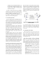
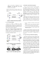
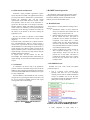
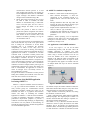
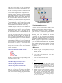
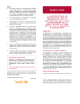
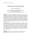
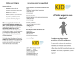
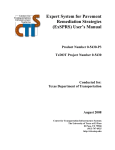
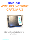
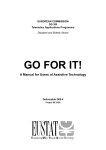
Architecture and Protocols of the RAMPE system- An Interactive Auditive Machine Helping Blinds in Public Transport Jinane El Sayah ESIEE/ESYCOM BP99 Noisy le Grand CEDEX France [email protected] Geneviève Baudoin ESIEE/ESYCOM BP99 Noisy le Grand CEDEX France [email protected] Abstract This paper presents the RAMPE system intended to assist and help blinds and visual-impaired people in public transportation. This system relies on a network which must provide open connection and access protocol for the user. The network architecture of this system is described along with the different protocols in use, their limitations and the possible enhancements. The simulation of the RAMPE application level with OMNET++ is also presented. Olivier Venard ESIEE/ESYCOM BP99 Noisy le Grand CEDEX France [email protected] Bachar El Hassan Lebanese University Tripoli, Lebanon [email protected] 2. RAMPE description and principle The RAMPE system (Figure 1) is based on: 1. Introduction Using the bus, the metro, the tramway or any kind of public transportation, be aware and in time, of urgent notifications and messages, is difficult for normal people, so how is the case with blinds? RAMPE [1, 6, 7, 8] initially stands for “Référentiel d'assistance aux personnes Aveugles pour leur Mobilité dans les transports publics et les Pôles d'Echanges” and that can be translated to Reference frame of Assistance to the Blind people for their Mobility in public transport. The project started in January 2004. It is supported by the PREDIT3 which is a French Program of Research, in the field of land Transport. The object is to conceive and develop, thanks to the use of new communication and information technologies, an active and interactive device for assistance and information to the passengers, particularly intended for the blind people. It should be installed in bus (or tramway) stops. This article is organized into 4 sections: section 1 is an introduction followed by, in section 2, a description of the RAMPE system. Protocols used in RAMPE are enumerated in section 3 along with their limitations and possible enhancements. Simulation of the application layer of the RAMPE system using OMNET++ is presented in section 4. Conclusion and perspectives are presented at the end of this paper in section 5. ˆFigure 1. RAMPE Architecture and components˜ A smart handheld device carried by the user. This device is a WiFi enabled PDA running the RAMPE application software. The Man Machine Interface is realized by Text to Speech Synthesis and the keys of the PDA. Fixed base-stations installed at the bus stops. They include a WiFi Access Point (AP) and a loudspeaker that can be remotely activated by the user. A client/server of information is also located in the station and connected to the WiFi access point. The stations are connected to the available transport information system. The RAMPE application in the PDA is divided into multiple steps: - Discover: in this step, the RAMPE application discovers the stops with RAMPE network enabled. - Choice: here, the blind can choose with which Stop to connect. - Connection: the blind or the PDA must connect to a certain Access Point in order to interact with it. - Download: the PDA downloads the database of the stop in order to know more detailed information about this stop. - Navigation into the downloaded database: once the blind downloads the database, he can navigate into with some “zooming” capabilities [7, 8]. Together with the ability of receiving urgent asynchronous messages. In order to achieve these steps, the RAMPE’s components must communicate and cooperate together using networking protocols. Some of these protocols are general or standard; some others were or must be developed specifically to the RAMPE application. Let’s begin by describing these protocols and the different steps of the RAMPE application: them to the blind. So in this phase, the discover phase, the PDA is still not associated. Its wireless network interface card is only listening to the radio channel. This permits to minimize the power consumption of the PDAs. By clicking the buttons of his PDA, the blind can request the association to one of the Access Points (figure 2) in order to obtain more information on the chosen stop. 2.1. Association procedure The Access Points specific to the RAMPE system are dispersed in the different bus stops. Now how does the WiFi Access Point located in the bus stop notify the user of its presence? As per the WiFi standard [2], each access point operates at the first 2 layers of the Open source Interconnection (OSI) model: the physical layer and the data link layer. The physical layer specifies the radio communication technique used. In the Data Link Layer, each Access Point sends periodically beacon frames at the rate of 1 frame each 0.1 seconds. This beacon frame broadcasts the Service Set Identifier (SSID) which is the descriptive/logical name of the Access Point, i.e the Local Wireless Network covered and served by this access point. In public transport context, the most important information characterizing a certain stop is: the name of the stop and the direction served by this stop. From this point of view, the SSID of the different Access Points in RAMPE system has a specific and common syntax: it starts with the keyword RAMPE then it is followed by the “stopPointName” separated from the “direction” by a slash (RAMPEstopPointName/direction). This syntax allows also recognizing that stop as RAMPE network enabled. The information provided by using the SSID is limited by the 32 characters limitation of the SSID. The wireless card of the PDA device carried by the user detects the presence of the Access Point when it arrives near it because it receives the beacon frames. The RAMPE application installed on the PDA can generate a chime or a jingle notifying the blind of the presence of 1 or more stops near him. If the blind acknowledges by pressing the acknowledge button of this PDA, then a vocal message is sent by the application to the Blind listing for him the names and the directions of detected stops. This is very practical as the blind doesn’t have to know the stations at a first stage. The application recognizes them as soon as the blind gets near them. Then the application enumerates the bus stops and lists ”Figure 2. Association Procedure of the PDA to the Access Point" An “Association wireless card of Access Point can frame. Now the Access Point. Request” frame [2] is sent by the the PDA to the Access Point. The send then an “Association Response” PDA becomes associated with the 2.2. Assignment of IP Address When the association is done, and in order for the PDA to become active and interact with the Access Point, it has to obtain an IP address and get the IP address of the Access Point. This is done via the Dynamic Host Configuration Protocol (DHCP) Protocol of the Application Layer. The DHCP Protocol provides configuration parameters to Internet hosts in a client-server model. DHCP server host allocates network addresses and delivers configuration parameters such as DNS and WINS addresses to other (client) hosts. This protocol is based on UDP, broadcast mode. It operates in four steps: DHCPDISCOVER: the host (or client) sends a frame in which it specifies the parameters (options) that it wishes to obtain (addresses IP, mask, DNS, footbridge...). - DHCPOFFER: The server answers by providing possible values for the options required by the client. - DHCPREQUEST: the client checks that these options are appropriate to him (coherent values), modifies them if needed, and confirms their final request near the server. - DHCPACK: the server then informs the client that the lease was reserved and confirmed. If the values of the options of REQUEST are not appropriate, the server does not return DHCPACK but DHCPNAK, and all the transaction is to be remade. After this whole process, the PDA obtains an IP address and can now interact with the Access Point (Figure 3). ˆFigure 3. IP address allocation procedure" 2.3. Access Point ringing 2.4. Database download and navigation After the successful association and DHCP request, the database from the server of the station is automatically downloaded into the PDA. This transfer is done with HTTP-GET methods of Layer 7 of the OSI model. This database is structured using a XML framework specified either by a DTD (Data Type Definition) or by a XSD (XML Schema Definition). This database is specific to each bus stop and contains information related to this stop. Also, it has a very limited size allowing the PDA to download it very quickly. Then and by the means of his PDA, the user can obtain detailed vocal information (served bus lines, routes, timetables) of the station which has just been selected. The blind can be in one of the following levels while browsing and navigating into the database (Figure 5): 1. Once the IP address is obtained, the station automatically rings a first time in order to help the blind to locate the stop in an auditive way. Then the user can ask the station to ring a second or a third time by doubleclicking a button of the PDA (Figure 4). This is done using the Transmission Control Protocol (TCP). It’s a connection oriented Protocol of the transport layer. Specific or proprietary Frames of the RAMPE system have to be exchanged in this case using the TCP Protocol. These frames are called of type “U”User frames or Identification frames. 2. 3. Level 1: Inventory of the lines served by this station. Level 2: Inventory of the Main stops (skeleton) starting from the stop station of the chosen line. Level 3: Inventory of all the stations that the bus will pass by, from the current station to the terminus of the line. As long as the user remains at one level, the vocal information is repeated in loop. The blind can pass from one level to another by clicking the buttons of his PDA. The function of each button is explained below in section 2.6. 2.5. Urgent messages and database updating ˜Figure 4. Ringing procedure and Database download" Vocal loop Vocal loop ACK Level 1 Vocal loop ACK Level 2 Level 3 ACK ˆFigure 5. Levels of the RAMPE application" The database information can change (updating of the database) or an urgent message can happen (accident, unforeseen disturbance, delay, arrival of the bus…). In this case, specific frames are sent by the AP to all the PDAs that are connected to it. In the case of an urgent message, the PDA receives the frame, stops navigating in the user interface and informs immediately of the urgent message using the text to speech synthesis. The blind must acknowledge the receipt of this urgent message. If not, the message will be repeated continuously in a Vocal loop until acknowledged. In the case of the database updating, the PDA receives the corresponding frame, downloads the database again, and informs the user (by a short clearly audible sound) of the new information available. The Refresh Frames “R” of the RAMPE system are exchanged in the case of database updating and frames of type “V” are indication of coming Vehicles. They are exchanged using the User Datagram Protocol (UDP) of the transport Layer in broadcast mode. 2.6. PDA buttons and functions 3. RAMPE Network protocols Transaction during RAMPE application requires actions from the user (blind). The application has thus to provide special means to maintain the “synchronization” between the application state and the mental representation of the blind about the external “world” and especially about the state of the transaction. A special care has been taken in the design of the ManMachine Interface (MMI). This MMI (as introduced in section 2 above) is realized by Text to Speech Synthesis and the keys of the PDA [8]. The blind can interfere by the means of the buttons of his PDA, making the application evolve. We summarize in this section the proprietary frames exchanged during the RAMPE application execution, and also the different protocols of the different OSI model layers used in the RAMPE system. We have two modes of operation of the RAMPE application: the “Normal” mode and the “Urgent” mode (Figure 6). In Normal mode, each button has a specific function: The “Acknowledgement” button is used to accept a certain event, to go into the next level while navigating into the database or to acknowledge an asynchronous (or urgent) message. The “Silence” button is used to put the speech synthesis in pause: it becomes silent except if an urgent message is received. The “Stop” button stops the RAMPE application completely. In Urgent mode, all the buttons let the user acknowledge. This will help the blind, when hearing an urgent message, not to be lost about which button he has to press. 3.1. RAMPE Frames These frames are currently defined according to three categories: Identification frames (U): these frames are always sent from the PDA towards the AP asking it to ring. Protocol used: TCP. Refresh frames (R): these are always sent by the AP towards the PDA. This frame is produced in case of variation of schedules or exceptional event which lasts a certain amount of time on a line. These changes are reflected in the base XML which the PDA must download further to a frame R. Protocol used: UDP in broadcast mode. Frames of indication of coming vehicles (or other exceptional messages) (V) - it is an urgent message, always sent from the AP towards one or more PDA. This frame is produced for example when a bus is coming towards the stop. Protocol used: UDP in broadcast mode. 2.7. Conclusion 3.2. RAMPE Protocols To summarize, the means used in the application protocol (structure of the SSID, unique name for all the databases) allow managing automatically the transaction involved in the RAMPE framework and does not require any user configuration. Once the database is downloaded, the user can freely navigate into it by pressing the buttons of his PDA, and he can be warned by RAMPE network with urgent messages that must be acknowledge. RAMPE uses TCP, UDP, HTTP and DHCP protocols (Figure 7). "Figure 6. PDA buttons and functions in RAMPE" TCP is a protocol of the transport layer, generally used above IP. It’s a connection oriented protocol used for reliable transmission of data. In RAMPE, once an AP has been successfully selected, the application proposes a guiding service using a TCP frame. ˆFigure 7. The 7 Layers of the OSI Model and Protocols involved in the RAMPE application˜ UDP: Compared to TCP, UDP is a connectionless oriented protocol. It is used when sending short messages, not requiring an acknowledgment from the receiver. In RAMPE, urgent messages and database information changes will be broadcasted using UDP. HTTP: This protocol is based on TCP via port 80, 8008 or 8080. In RAMPE, the XML database is downloaded using a HTTP-GET service. From this point, the user is able to browse through the details of the chosen station. DHCP: this protocol is based on UDP. It permits the dynamic assignment of IP address to a terminal, in our case to the PDA. When the PDA chooses an AP to associate with, it will obtain an IP address, permitting it to ring the AP and interacts with it. We can see that urgent messages are broadcasted using UDP. With UDP, the stop or the access point doesn't have to manage the connections of all the blinds associated with it. It broadcasts the messages independently of whom or how many users are connected to it. The users are moving, and managing continuously all the connections would burden the server application and would be a drawback for real-time constraint. With a connection oriented protocol like TCP, some latency may be observed due to successive acknowledges’ overheads. We have to wait for the acknowledgment of each PDA and this is not practical as it may suffer from delays and latency. That would be the case if we are considering an area with a concentration of blinds (a school for example) and they want to get out simultaneously taking the bus. On the other hand, since UDP is connectionless, the application is not able to check if messages arrive successfully because no acknowledgment is required. The goal in the future is to elaborate a session protocol adding more reliability than UDP but at the same time faster then TCP in order to resolve this issue. 4. Simulation of the RAMPE application level using OMNET++ OMNeT++ (Objective Modular Network Testbed in C++) [4, 5] is a discrete Event Simulator. It is used by many research groups for communication network performance estimation. Models and system can be simulated and shown in a graphical and interactive manner. The utility of simulating the RAMPE application in OMNET++ is that this network simulator is useful for illustration, debugging, evaluation and performance improvement purposes. It provides a collection of tools that help modifying or implementing new features in an easy fashion. In the following, we describe the framework used to simulate the application level of the RAMPE application. 4.1. OMNET++simulation components An OMNeT++ model consists of the following parts: - NED (Network Description): it shows the components of the simulated network in a graphical manner. These are files with the .ned suffix. - Message definitions: files with .msg suffix. The message file shows the different message types exchanged between all the components. - Simple modules implementations and other C++ code, in .cc files (or .cpp, on Windows). - Configuration files indicating the network to be simulated and the value of some variables or parameters. OMNET++ allows specifying a set of components connected to each other by IO ports through which messages are send and received. The simulation is scheduled by message events. 4.2. Application to the RAMPE simulation In our case, Figure 1, we can see the blind communicating directly with his PDA where the RAMPE application is installed. The PDA communicates with the access point located in the bus station using a wireless connection. The AP can access the database server. This configuration is defined in the NED file which corresponds to the graphical representation shown in Figure 8 where each application entity appears as a module. The case of multiple blinds and stops can also be simulated (Figure 9). ˆFigure 8. RAMPE Architecture in NED˜ The number of stops, the number of blinds or PDAs, the PDA button that the blind will press at any time can be determined using one of the following methods: - “Input” function: it interactively asks the user, during the simulation, to enter his choice. - “XML” configuration file: XML stands for eXtensible Markup Language. The original purpose of XML is to describe structured data thus making it important as a data storage and interchange format. Since XML is a way to describe structured data there should be a means to specify the structure of an XML document. This is the purpose of a Document Type Definition (DTD). It defines the legal building blocks of an XML document. It defines the document structure with a list of legal elements. An XML document that conforms to a DTD or schema is considered to be valid. As XML is increasingly becoming a standard format for configuration files, OMNeT++ had, from the 3.0 version, a built-in support for XML configuration files. Sometimes modules need more complex input than simple module parameters can describe. Then you’d put these parameters into an external XML configuration file, and let the modules read and process the file. You’d pass the file name to the modules in a string parameter. This machinery can be accessed via the NED parameter type xml. You can point xml-type module parameters to a specific XML file (or to an element inside an XML file) via the xmldoc() operator. You can assign xml parameters both from NED and from omnetpp.ini [4]. ˆFigure 9. Components exchanging messages between them˜ 5. Conclusion and perspective In RAMPE, multiple scenarios have to be simulated and this was the benefit from using XML: for example, one blind can chose to ring the access point a second time and a third time maybe, other one can simply click on the acknowledgment button to download directly the database…. etc. In the XML and DTD samples below, we can see the profile of the first blind with id=0. “Bip” indicates the action to be taken by this blind when receiving a bip sound signalling the presence of Access Points near him. He is acknowledging, asking the application to enumerate all the available lines. “Connect” indicates the action to be taken by the blind when the application asks him if he wants to connect to an Access Point. Once connected, the access point rings automatically and then asks the blind if he wants to ring it again or download directly the database. This action is reflected by the variable “Association”. In this paper, we introduced the RAMPE system architecture, its simulation using OMNET++ and the different protocols used along with their limitations. One limitation of the current version of the RAMPE system is in using a communication protocol between the access point and the different associated PDAs as discussed before. This constitutes an interesting continuing of this article. In parallel with this specifications and simulation work, a fully operational hardware and software realtime platform has been realized thanks to a grant of the PREDIT 3 program. This platform will be experimented in-situ on a public transport infrastructure. The RAMPE system will be evaluated both on the technical point of view (software and network reliability, real-time constraints,…) and from user point of view (use, ergonomics, …). <!DOCTYPE configurations SYSTEM "note.dtd"> <configurations> <config id="0" bip="ack" connect="sil" association="ack" [1] G.Baudoin, O.Venard, G.Uzan, Y.Benabou, A.Paumier, .“RAMPE - Rapport final de la phase 1”, final report PREDIT 3, June 2005. DTD file is created as well to interpret building blocks and variables used in the XML. <!ELEMENT configurations (config?,config1?)> <!ELEMENT config (#PCDATA)> <!ATTLIST config id CDATA #IMPLIED> <!ATTLIST config bip CDATA #IMPLIED> <!ATTLIST config connect CDATA #IMPLIED> <!ATTLIST config association CDATA #IMPLIED> Association request message, association response, frames “R”, “U” and “V” (see section 3.1), are defined in message definition files (*.msg suffix). In Figure 9 below, we can see these messages going back and forth between the different components. 6. References [2] IEEE Std 802.11-1999, Part 11: Wireless LAN Medium [3] Access Control (MAC) and Physical Layer (PHY) specifications, 1999 [4] Andras Varga. OMNeT++- Discrete Event Simulation System. User Manual. March 29th, 2005. [5] Jeroen Idserda. TCP/IP modelling in OMNeT++. July 6th, 2004 [6] http://www.esiee.fr/~rampe/ [7] G. Baudoin, O. Venard, et al, “The RAMPE Project: Interactive, Auditive Information System for the Mobility of Blind People in Public Transports”, Proc. of the 5th international conference on ITS Telecommunications ITST 2005, Brest France, June 2005. [8] G.Baudoin, O.Venard, G.Uzan, A.Rousseau, Y.Benabou, A.Paumier, J.Cesbron, “How can blinds get information in Public Transports using PDA? The RAMPE Auditive Man Machine Interface”, Proc. 8th European conference for the advancement of assistive technology in Europe, aaate 2005, Lille, Sept. 2005.