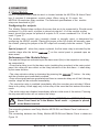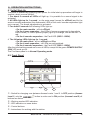
1
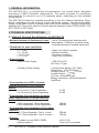
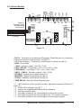
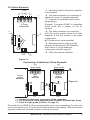
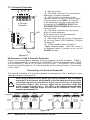
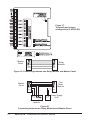
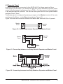
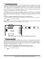
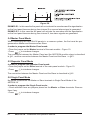
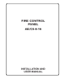
FIRE CONTROL PANEL AE/C5-8-16 INSTALLATION AND USER MANUAL Installer Instruction Contents 1. General Information......................................................................................4 2. Technical specifications..............................................................................4 2.1 Conventional Panel ................................................................4 2.2 Relay Module ...........................................................................5 3. Installing the AE/C5-8-16...............................................................................6 3.1 Wall Mounting.............................................................................................7 3.2 Flush Mounting...........................................................................................7 3.3 Configuration of the Basic Modules............................................................8 3.4 Control Module...........................................................................................9 3.5 Main Power Supply Source........................................................................10 Connecting to the Main Power Supply Terminal...........................................10 Connection of the Battery.............................................................................10 3.6 4 Zone Expander........................................................................................11 Connecting of Additional 4 Zone Expander..................................................11 3.7 4 Sounder Expander..................................................................................12 Connection of 4 Sounder Expander.............................................................12 4. Connecting 4.1 Relay Module AE/C5-8-16.........................................................................13 4.2 Repeater Module........................................................................................15 4.3 Remote Reset Mode.................................................................................. 16 4.4 Connecting the zone and sounder circuits.................................................16 5. SYstem programming 5.1 Delayed Sounders Mode............................................................................18 5.2 Immediate Action Mode..............................................................................19 5.3 Double Action Mode...................................................................................19 5.4 Master Panel Mode....................................................................................20 5.5 Slave Panel Mode......................................................................................20 5.6 Single Panel Mode.....................................................................................20 6. Operation instructions 6.1 Plus Switchig On - Initially Start-up............................................................21 6.2 Front Panel.................................................................................................21 6.3 Keypad.......................................................................................................22 6.4 LED Indication............................................................................................22 6.5 Sound Signallization...................................................................................23 6.6 Engineers Facilities....................................................................................23 7. Indication 7.1 Indication of Technical Troubles.................................................................26 7.2 Indication of Service Modes.......................................................................27 General connection circuit of MAG4 Plus...............................................28 Fire alarm record...............................................................................................29 Service record.....................................................................................................30 Fire alarm event log..........................................................................................30 Spare parts kit......................................................................................................31 AE/C5-8-16 - Installation and operation Manual AE/C5-8-16 - Installation and Operation Manual 1. GENERAL INFORMATION The AE/C5-8-16 is a conventional microprocessor fire control panel, designed according to EN54 Standard requirements. The panel provides for monitoring and reporting fire events in up to 16 separate zones, depending on the installed configuration. The AE/C5-8-16 must be installed according to the Fire Alarm Installation Regulations, mandatory for the territory of the respective country. The electrical power supply to the panel must be isolated and must not be capable of being accidentally switched off. The power switch-off board should display a clear FIRE ALARM - DO NOT SWITCH OFF label. 2. TECHNICAL SPECIFICATIONS 2.1 general Tecnical Specifications of AE/C5-8-16 ▪ Maximum number of detectors per zone: ▪ Thresholds for zone conditions: • 0 ÷ 2 mA • 2 ÷ 10 mA • 10 ÷110 mA • > 110 mA ▪ Power Supply: • Main Power Supply - Up to 32 conventional detectors with consumption < 200µА at a normal mode; - Unlimited number of manual call points. - Open circuit fault condition. - Normal condition. - Fire alarm condition. - Short circuit condition. ~ 230V AC ±10% 2А Fuse, F-Type. • Standby Power Supply 1 Accumulator battery 12V/ 18Ah Dimentions - 167х181х76mm Voltage Output - UCHARGE = 13,8V Current Output - IMAX = 2A 7А Fuse, Automotive type Battery connection: with a flat terminal lug Ø5mm ▪ Consumption from 230V in normal working mode and a fully charged battery: • At 4 zones (1 Zone Expander) 2,1VA • At 16 zones (4 Zone Expanders) 4,2VA ▪ Consumption from the battery at mains power supply failure in normal working mode: • With connected 1 Zone Expander 130mA • With connected 4 Zone Expanders 260mA ▪ Consumption from the battery in Fire alarm condition: • At 1 Zone Expander, Fire in 1 zone 330mA • At 1 Zone Expander, Fire in 4 zones 720mA ▪ Outputs: • Sounder circuits SND1÷SND4 +24V/ 0.3A (control module) Fuse, self-recoverable AE/C5-8-16 - Installation and operation Manual • Sounder circuits SND1÷SND4 (4 Sounder Expander) • Fault Relay, volt free changeover contacts* • Fire Relay, volt free changeover contacts* * Note: These functions may not be used to provide any “Options with requirements” as specified in EN54-2. • Auxiliary autput ▪ Cabling of the main power supply: • Recommended wires cross section • Terminal maximum wire diameter ▪ Environment: • Working temperature • Storage temperature • Humidity +24V/ 0.15A Fuse, self-recoverable +12V/ 1A or 24V/ 0.5A UMAX = 125V; IMAX = 2A +12V/ 1A or 24V/ 0.5A UMAX = 125V; IMAX = 2A +24V DC/ 0,3А Fuse, self-recoverable 1.5mm2 Ø2.5mm -5 ÷ +40ºС -20 ÷ +60ºС Up to 93% (non condensing) 2.2 general Tecnical Specifications of Relay Module ▪ Number of relays: ▪ Power supply: ▪ Current consumption in normalcondition: ▪ Additional current consumption for every relay switched ON: ▪ Maximum ratings of volt-free changeover contacts:: ▪ Maximum voltage: ▪ Maximum consumption: ▪ Cabling: • Recommended wires cross section • Terminal maximum wire diameter ▪ Environment: • Working temperature • Storage temperature • Humidity 8 24V 8mA 10mA 12V/ 1A или 24V/ 0.5A 125V 2A 1.5mm2 Ø2.5mm -5 ÷ +40ºС -20 ÷ +60ºС Up to 93% (non condensing) WARNINGS: ! Prior to connecting the AE/C5-8-16 Fire Alarm Panel, perform a thorough test of the all wiring integrity of the entire system. Should a fault arise during installation and connection, which cannot be removed, stop the installation and call the producer or his regional authorized representative! AE/C5-8-16 - Installation and Operation Manual 3. Installing the AE/C5-8-16 • Select the best location for the panel away from sources of heat, environmental dust and potential water ingress, with an ambient temperature of between -5°C and + 40°C, Figure 1. • Undo the two secure bolts - Figure 2. Use the instrument supplied for the purpose in the set (hexagonal tool No. 2). • Open the front panel and disconnect the earth cables: from the 230 V clamps, from the metal bottom clamps and from the chassis. • Disconnect the indication ribbon cable. • Remove the front panel by undoing the screws of the hinges - Figure 3. (NB. The screws at the metal bottom can also be undone. What is special here is that there are two plastic pads under the very hinges. These pads need to be placed back again under the hinges when mounting the front panel.) • Select the input openings for the cables and place a plastic cap, provided with the panel accessories, on those which are not going to be used, see Position 13 from the spare parts kit on page 31. • Perform an exposed or flushed mounting - see §3.1 and §3.2. • Run all external cables into the box to establish connection but do not connect them at this stage yet. Run the mains cable through the chosen opening but keep it away from the low voltage wirings. • Connect the mains supply and earth to the main terminal block but do not switch the main electrical supply on at this stage. • Position the battery and secure it with the clamp - Positon 1, Figure 9. • Place the plastic light guides (see Positions 11, 15 and 19, page 31), provided with the spare parts kit, at their designated locations on the main module, zone and/or sounder expanders. • Connect the zone and sounder circuits and program the panel according to the specific application. • Mount the front panel back onto the hinges and connect the indication ribbon cable and the earth cables: to the 230 V clamps, to the metal bottom clamps and to the chassis. • After all system programming and testing operation are complete, screw both secure bolts with the help of the hexagonal tool supplied. Figure 1. Figure 2. AE/C5-8-16 - Installation and operation Manual Figure 3. 3.1 Wall Mounting • Use the template supplied to determine the openings of the metal bottom onto the wall - Figure 4. • Drill Ø6-8mm diameter openings in the wall and fix the box using the provided anchors and screws (Positions 2 and 6, page 31) - Figure 5. TEMPLATE DRILL HERE FLUSH MOUNTING Figure 4. Figure 5. 3.2 Flush Mounting The accessory set provided contains two special hangers for flushed wall mounting of the fire alarm panel on 25 mm thick drywall. • Use the dimension shown in Figure 6 to draw and cut out the mounting openings in the drywall. • Attach the hangers to the internal side of the wall and fix them with the screws (Position 8, page 31), as shown in Figure 7, Position 1. • Run all external cables in the box and then place it into the mounting opening. Fix the bottom using the mounting screws and washers (Positions 5 and 7, page 31) - Figure 7, Position 2. 25mm THICK DRYWALL METAL BOX HANGER SCREWS FOR HANGER FIXING WASHER Figure 6. SCREWS FOR FLUSH MOUNTING Figure 7. AE/C5-8-16 - Installation and Operation Manual Figure 8. Flush mounting holes. Main view of the fixed to the wall hangers and the bolts supporting the metal box. CONTROL MODULE 5 4 ZONE EXPANDER 3.3 Configuration of the Basic Modules 3 MAIN POWER SOURCE 4 1 3 2 Figure 9. • 1 - Metal clamp for supporting the battery. • 2 - 7A Fuse, Automotive type (Position 4, page 31). • 3 - Clamp for supporting the main power supply cable. • 4 - Terminal for connecting between the mains power supply and the power source. F-type fuse 2A (Position 3, page 31). • 5 - Earting point. AE/C5-8-16 - Installation and operation Manual 3.4 Control Module SND 4 SND 3 SND 2 SND 1 FIRE FAULT RELAY RELAY NO COM NC NС COM NО Table for Sounder Delay Programming (in minutes). Tx +AUX GND CC Rx + _ + _ + _ + _ 4 MASTER SLAVE DOUBLE POWER 5 EXP 1 2 TIME 3 DELAY 4 6 1 10 10 10 10 10 10 9 8 7 6 5 4 3 2 1 0 Time delay (in minutes) 2 uPFault SND1 SND2 SND3 SND4 KEYBOARD FAULTS EARTH AUX RPT AC BATT LOW/LOST 7 3 Figure 10. • Rx/Tx - Terminals for connecting of Repeater, Relay Module or a combined connection between them (see §4.1 and §4.2); • CC (Class change) - Terminal for connecting of a switch (see §4.3); • GND - Grounding; • +AUX - Auxiliary output, +24V DC / 0,3A; • FAULT RELAY - Fault Relay, +12V / 1A or +24V / 0,5A; • FIRE RELAY - Fire Relay, +12V / 1A or +24V / 0,5A; • SND 1 ÷ SND 4 - Sounder outputs, +24V / 0,3A; • DOUBLE - Double Action Mode (see §5.3); • MASTER - Master Panel Mode (see §5.4); • SLAVE - Repeater Panel Mode (see §5.5); • TIME DELAY - Sounder Delay Programming. • - LED Indication of the operation modes, light guide mounted (Position 11, page 31); • - Faults LED indication, see §7.1; • - Jumper for enable/disable Earth Fault Indication; • - Self-recoverable fuses; • - Flat cable connector for connecting the main power source; • - Flat cable connector for connecting 4 zone / 4 sounder expander; • - Flat cable connector for connecting the control panel keypad. AE/C5-8-16 - Installation and Operation Manual 3.5 Main Power Source Black Yellow-green F-Type Fuse 2А Black Connecting of the Main Power Supply Main Power Source ! Red LED indication of main power supply presence. The yellow-green earthing cable of the main power source must be connected to the middle point of the terminal! Black Black Yellow-green Figure 11. Connecting of the Battery Figure 12. Main Power Source Black Red Fuse Attention: It is possible that the battery might not be charged at the panel initial start-up. In this case the BATT LOW/LOST at the control module and the GENERAL FAULT at the front panel will light on until the battery will be charged up to the required level. Note: The accumulator battery fuse is 7A (7,5A), automotive type and is sutueted in the holder connected to the red cable of the main power source - Figure 12! 10 AE/C5-8-16 - Installation and operation Manual 3.6 4 Zone Expander 1 ZONE 3 2 z1 z2 z3 4 z4 1 4 Zone Expander 4 2 6 5 z1z2 z3 z4 1 2 34 ZONE • 1 - Mounting holes for fixing the expander to the chassis. • 2 - Flat cable connector for connecting of additional 4 zone / 4 sounder expander. • 3 - Jumpers for Immediate action mode programming. Example: To program ZONE1 in immediate action mode put a jumper on the z1 terminal. • 4 - Flat cable connector for connecting: а) To the control module, when the 4 zone expander is the first module in the panel configuration. b) To a previous 4 zone expander; • 5 - Mounting holes for placing a light guide for the front panel LED indication, see Position 11 of the additional components included, page 31. • 6 - LEDs Zone status indication. 3 Figure 13. Connecting of Additional 4 Zone Expander 1 ZONE 3 2 z1 z2 z3 4 5 ZONE 7 6 z4 z1 z2 z3 8 z4 First Second Control 4 Zone 4 Zone module Expander Expander MAG4Plus Figure 14. z1z2 z3 z4 z1z2 z3 z4 1 2 34 5 6 78 ZONE ZONE • 1 - Connect the flat cable connectors of the expanders. • 2 - Fix the second 4 zone expander with screws to the metal box frame. • 3 - Place the light guide (Position 15, page 31) The metal box of AE/C5-8-16 can accommodate up to 4 zone expanders. To each zone can be connected up to 32 conventional detectors with consumption <200µA at normal operation mode and unlimited number of manual call points. AE/C5-8-16 - Installation and Operation Manual 11 3.7 4 Sounder Expander SND 4 SND 3 SND 2 SND 1 • 1 - Mounting holes. • 2 - Flat cable connector for connecting of additional 4 sounder expander. • 3 - LED indication for troubles in the sounder circuits. In case of a trouble in any of the sounder circuit SND1 - 4 the LED of the respective sounder circuit will light on together with GENERAL FAULT and SOUNDER FAULT/DISABLE indicators on the front panel. • 4 - Flat cable connector for connecting: а) To a 4 zone expander. b) To a previous 4 sounder expander. c) To the control module.* • 5 - Mounting holes for placing a light guide for the front panel LED indication, Position 19, page 31.* • 6 - LEDs Sounder status indication.* * Note: Just in case, when the panel is in Repeater Mode (a jumper is put on the SLAVE terminal). 1 4 Sounder Expander 4 2 6 5 SND1 SND2 SND3 SND4 3 Figure 15. Performance of the 4 Sounder Expander There is a correspondence between the zone numbers and the sounders - ZONE 1 of the 4 zone expander corresponds to SOUNDER 1 of the 4 zone expander, ZONE 2 to SOUNDER 2, and so on. In case of fire in ZONE 1, SOUNDER 1 will operate continuously and Sounders 2 ÷ 4 of the expander will be pulse activated – 2 sec. sound / 2 sec. silent. Connecting of 4 Sounder Expander The method of adding of 4 sounder expander is analogical to that of adding a 4 zone expander module, see Figure 14. ! Note: Only a module of the same type can be added to the 4 sounder expander. For the proper performance of the fire alarm panel observe the connection sequence presented in Figure 16a. In the case of improper connection (Figure 16b), an error signal will be generated when the power supply is switched on - the LEDs of the zones connected after the 4 sounder expander begin to blink and the GENERAL FAULT LED remains permanently lit. zones 1 2 3 4 Control panel First 5 6 7 8 Second 4 Zone 4 Zone Expander Expander sounders zones sounders zones 1 2 3 4 1 2 3 4 1 2 3 4 5 6 7 8 First 4 Zone Expander First 4 Sounder Expander Second 4 Zones Expander First 4 Sounder Expander а) Control panel Figure 16. 12 AE/C5-8-16 - Installation and operation Manual b) 4. Connecting 4.1 Relay Module MR8 is a supplementary module which is located outside the AE/C5-8-16 Alarm Panel box. It contains 8 changeover contact relays. When using all 16 zones, the AE/C5-8-16 needs two relay modules. The technical specifications of the module relays are described in §2.2. Configuring the outputs The Module Relays helps configure the zones that are to be connected to. Should zones numbered 1 to 8 be used, a jumper is placed at outputs 1÷8 of the module mother board; should the jumper be placed at outputs 9÷16, zones numbered 9 to 16 will be used - Figure 17. The module relay contact type (normally closed or normally open) is determined by configuring the NO/NC outputs. Placing the jumper at the NO output will normally open the contact; placing the jumper at the NC output will normally close the contact - Figure 17. Special jumper J1 - when this jumper is placed, the first zone relay is activated by the module relays after the button on the control panel is pressed upon an alarm event. Performance of the Module Relays The module Relays are activated upon an alarm event (fire) in the respective zone they are connected to. • Given that a delay is set for the alarm cycle (enabling the sounders) in the main control panel, this delay will also reflect on the relay activation of the first alarm - it shall delay by the same duration. • The relay activation delay is eliminated by pressing the button - the relay and the sounders are immediately enabled. • Once a fire signal has been generated and there is a sounder delay set off, the following module relays will be activated immediately. • The respective relay is enabled immediately after the sounders are activated. Where there is any delay, it shall apply only to the relay of the zone that first entered the alarm mode. • The active relays are disabled immediately after an initial reset of the station. Pressing the stop sounder button will not restore the relays. ! In order to operate together with the AE/C5-R8, the AE/C5-8-16 Fire Alarm Panel must be in the Master Panel mode – a jumper is placed at the Master terminal. The connecting between one Relay Module AE/C5-R8 and Master Panel is shown on Figure 18. The connecting between two Relay Module AE/C5-R8 and Master Panel is shown on Figure 19. AE/C5-8-16 - Installation and Operation Manual 13 Figure 17. Terminals and jumper configuration of AE/C5-R8. Master Panel GND +AUX GND +24V Relay Module Figure 18. Connecting between one Relay Module and Master Panel. Master Panel GND +AUX GND +24V +24V GND GND +24V First Relay Module Power Supply +24V Second Relay Module Figure19. Connecting between two Relay Modules and Master Panel. 14 AE/C5-8-16 - Installation and operation Manual 4.2 Repeater Panel A second Panel can be connected to the AE/C5-8-16 Fire Alarm panel as Slave. The function of the Slave is to double the light and sound indications and the button control of the first panel at a distance of up to 1000 m. For the purpose, both panels have to be assigned specific priorities: The first fire alarm panel shall be the system Master and the second - Slave. The Master panel is configured by placing a jumper on the Master terminal of the main module, and the Slave - on the Slave terminal (see Figure 10). Figure 20 shows the connection between the Master and Slave AE/C5-8-16 panels. Master Panel Repeater Panel Figure 20. Connecting between Repeater and Master Panel. Repeater Panel Master Panel +24V GND GND +AUX Relay Module Figure 21. Connecting between one Relay Module, Repeater and Master Panel. Figure 22. Connecting between two Relay Modules, Repeater and Master Panel. AE/C5-8-16 - Installation and Operation Manual 15 4.3 Remote Reset Mode To use the class change function connect the terminals of a switch with normally open contacts to the CC clamps of the main module terminal (Figure 10). When the switch is depressed the start-up procedure begins. 4.4 Connecting the Zone and Sounder Circuits Verify the normal functioning of the panel before connecting circuits to zones and sounders: • Connect the battery to the power unit terminals - Figure 12 and check the availability and condition of the fuse, a 7A automotive type, located in the clamp. • Check the availability and condition of the fuse, a 2A F-type, located in the clamp for connecting the power unit to the main electric network. • Turn on the main power supply. ! In normal working mode only the “Power Supply 230V” LED lights up on the front panel of the fire alarm station. NOTE: In case other indicators are also lit and the internal buzzer has been activated: • Disable the buzzer signalization with the button on the front panel. • Check the mains and the battery fuses. • Check the electrical connections within the station box. • Check for any activated FAULTS LEDs of the main module, see Figure 10. Specify the faults according to the Fault Indications Table on page 26. • Press the button on the front panel to reset the system (the button is active if the switch is in an ON position). Connecting the Zone Circuits ! 16 D1 СР1 DN EOL ZONE Up to 32 conventional fire detectors and an unlimited number of manual fire alarm buttons can be connected to each circuit. Figure 23 shows how to connect detectors within a zone. Figure 23. Connecting of detectors (D1÷N) and manual call points (CP1÷N) to the zone circuit. Attention: During Double Action mode of work of the panel, where the zone expander has NO jumper on the terminal for immediate action of any zone, ONLY detectors can be connected to its circuit, and if a jumper has been placed - detectors and call points. Example: If there are call points connected in ZONE 1, for the system to function properly there must be a jumper at its zone expander at z1 terminal, see also Figure 25. AE/C5-8-16 - Installation and operation Manual In order to connect the zone circuits: • Shut down the mains supply and disconnect the terminals of the main power source to the battery. • Remove the EOL-modules from the clamps of all used zones and fit them on the last detectors. • Connect each circuit to a separate zone on the terminal of the 4 zone expander. • Connect the battery to the power source and apply mains power to the panel. ! After powering up the panel should be in normal working mode and the “Power Supply 230V” LED lights up on the front panel of the fire alarm station. NOTE: If the GENERAL FAULT LED lights up and a fault indicator has been activated for one or more zones on the front panel, the problem lies with the connection of the circuits in these zones. Check the polarity of the connection of the devices and whether any detector has been removed from its base. • Activate one or more detectors to each connected zone to verify that fire signals are generated and also that the panel functions correctly. Connecting of FAULT and FIRE Relays The relays with changeover contacts are intended for control of low voltage devices. ! Attention: No mains power should be supplied to the clamps of the FAULT and FIRE relays. After the connection is established, test each of the circuits for external device control. Connecting of Sounder Circuits Sounders Figure 24 shows how to connect the sounders. One R=10K resistor is connected to the end of each circuit as shown in the diagram. S1 S2 SN 10K LEGEND black red brown Figure 24. Connecting of sounders to SND1÷SND4 outputs of the control module and the output of the 4 sounder expander. AE/C5-8-16 - Installation and Operation Manual 17 In order to connect the sounder circuits: • Shut down the mains supply and disconnect the terminals of the power unit to the battery. • One by one remove the resistors (R-10K) from the sounder connecting clamps (SND1÷SND4) on the main module and connect them in parallel to the last sounder of each of the circuits. Connecting the sounders to outputs of 4 sounder expander is done in an analogical manner. • Connect the sounder circuits to the SND1÷SND4 clamps on the main module and/or on the 4 sounder expander by observing the polarity. • Connect the battery to the power unit and apply the main power supply. ! After powering up the panel should be in normal working mode and the “Power Supply 230V” LED lights up on the front panel of the fire alarm station. NOTE: If the GENERAL FAULT LED lights up on the front panel together with any of the FAULTS LEDs of the main module and/or the 4 sounder expander - SND1÷SND4, perhaps there is a problem in the connection. Check the polarity of the connection to the terminal of the main module of the panel, as well as the connection to the 4 sounder expander. 5. System programming 5.1 Sounder Delay This is an option for setting a delay on the Sounders activation when the panel enters “Fire” mode. The indication on the front panel - the FIRE LED, however, will light up immediately in case of a fire event, regardless of whether a delay has been set to enable the sounders. After the programmed delay period expires, during which the user can possibly find out the cause for the alarm event, the panel enables the sounders. The sounders can be silenced by pressing the on the front panel. In case of a false fire alarm the user must press the working mode. button to return to normal In order to program MAG4 Plus for Sounder Delay over an interval between 1 and 10 minutes: • Examine the Table of Instructions for programming sounder delay, shown on Figure 10. • Depending on the selected time delay, place a jumper at the TIME DELAY terminals, marked in Figure 10 as 1, 2, 3, and 4. • Press to introduce changes. Example: In order to program sounder delay of 3 minutes, place jumpers on terminals 1 and 2. 18 AE/C5-8-16 - Installation and operation Manual 5.2 Immediate Action Mode Where in the armed site there are zones, which need the sounders and the light indicators to be enabled instantaneously, the panel provides Immediate Action working mode. This mode can be programmed individually for every single zone, depending on its designation. In Immediate Action mode, in case of an alarm event occurring in the zone, the sounders are immediately enabled, i.e. this mode is of priority by zones compared to Double Action and Sounder Delay modes. In Double action mode of work of the panel, where there is no jumper on immediate action terminals of the zone expander, ONLY detectors can be connected to each zone circuit, and if a jumper has been placed - that allows connecting both detectors and call points. In order to program Immediate Action mode for a selected zone: • Place a jumper on the terminal that corresponds to the number of the zone - Figure 13. • Press to introduce changes. Example: If there are call points connected in ZONE 1, for the system to function properly there must be a jumper at its zone expander at z1 terminal. z1 D1 СР1 DN EOL Zone 1 z1z2 z3 z4 z2 4 Zone Expander z3 z4 Figure 25. Example for Immediate Action Mode Programming. 5.3 Double Action Mode The purpose of introducing a Double Action mode is to avoid false alarms. Where the Panel has been programmed to function in this mode, in the case of a fire signal, the panel does not alarm at once but waits for the alarm event to be repeated within a specific time interval - Figure 26. The time interval has been set by default and cannot be adjusted. For AE/C5-8-16 it is 3 minutes. In order to program the fire alarm panel for Double Action mode: • Place a jumper on the DOUBLE terminal of the main module - Figure 10. • Press to introduce changes. AE/C5-8-16 - Installation and Operation Manual 19 Time Time Figure 26. Example 1: In this case the fire panel will not activate the sounders and the signalization on the front panel because during time interval 2 no second alarm signal is generated. Example 2: In this case the fire panel will activate the sounders and the signalization on the front panel because during time interval 2, two alarm signals are generated. 5.4 Master Panel Mode When connecting two AE/C5-8-16 panels in a common system, the first must be programmed as Master and the second as Slave. In order to program the Master Panel mode: • Place the jumper on the Master terminal of the main module - Figure 10. • Press to introduce changes. The connection between the Master Panel and the AE/C5-R8 module relays is described in §4.1, and the connection between the Master Panel and the Slave - in §4.2. 5.5 Repeater Panel Mode In order to program the Repeater Panel mode: • Place the jumper on the Slave terminal of the main panel module - Figure 10. • Press to introduce changes. The connection between the Master Panel and the Slave is described in §4.2. 5.6 Single Panel Mode No jumper is placed on the Master or Slave terminals in Single Panel Mode of the AE/C5-8-16. In order to program the Single Panel mode: • Check whether there are jumpers placed on the Master or Slave terminals. Remove them if any. • Press 20 to introduce changes. AE/C5-8-16 - Installation and operation Manual 6. Operation instructions 6.1 Initial Start-Up The panel is enabled by supplying main power. An initial start-up procedure will begin to execute, which runs as follows: 1. For about 2 seconds all LEDs will light up; it is possible for a sound signal to be activated. 2. All LEDs light up for 1 second - on the main panel (except for uPFault) and for the zone or sounder expanders (the dichromatic LEDs of the zone/ sounder expanders light up in orange). The sound signalisation is activated. 3. For about 5 seconds the following LEDs light up: • On the main module - all but uPFault; • On the 4 zone expanders - the LEDs of zones programmed in Immediate Action mode (i.e. with a placed jumper) light up in orange, and all the rest - in red; • On the 4 sounder expanders - the Fault LED (SND1 - SND4). 4. The following LEDs light up for 1 second: • On the main panel - all but uPFault and Fire; • On the 4 zone expanders - all LEDs are extinguished; • On the 4 sounder expanders - the Fault LED (SND1 - SND4). After the initial setting procedure is over all LEDs, except for the green POWER SUPPLY 230V LED must go out. The Fire Alarm panel is in Normal Operating mode. 6.2. Front Panel 3 2 EN 54 PP 2006 1 4 5 - Switch for changing over between Access Levels 1 and 2. In OFF position (Access Level 1) only the button is active and in ON position (Access Level 2) all buttons are active. - Working modes LED indication. - LED indication on zone status. - Control buttons. - Instructions for working with the station. AE/C5-8-16 - Installation and Operation Manual 21 6.3 Buttons Button Description Activating sounders. Deactivating sounders. Deactivating the internal buzzer. Initializing of the start-up procedure. Confirming the introduced changes. Enabling / Disabling of zones / sounders. Test Mode; scroll forward zones. 6.4 LED Indication LED Description FIRE (two red) Fire in the premises. GENERAL FAULT (yellow) Main Fault indicator. SOUNDER FAULT/DISABLE (yellow) Lights permanently at disabled sounders. Blinks at trouble in the sounder circuit. OUTPUT DELAY (yellow) Lights permanently at programmed outputs time delay (a jumper is put on the TIME DELAY terminal). ENABLE/DISABLE (yellow) Lights permanently at disabled zones/sounders. Blinks during enabling/disabling of zones or sounders. TEST (yellow) Blinks during “One Man” Test of a zone. POWER SUPPLY 230V (green) Blinks permanently in normal operating mode, indicates presence of main power supply 230V. LED 1- 16 (yellow-red) Zone indication. Lights up in red at Fire in the zone. Lights up in yellow at disabled zone. Blinks in yellow: - 1 blink per second at trouble in the zone; - 2 blinks per second at “One Man” Test and disabling of zones. 22 AE/C5-8-16 - Installation and operation Manual 6.5 Sound Signalization • Short beeps - After pressing the and upon the initial start-up of the panel • Continuous beep - Fire and/ or Fault status. The signalisation can be stopped by pressing the button, but the LED indication remains. • Interrupted beep - After pressing the sounders and the button to allow or disallow zones/ button to access “One Man” test mode of zones. The sig- nalisation can be stopped by pressing the remains. button, but the LED indication 6.6 Service Modes Zone Enable / Disable Each zone of MAG4Plus can be enabled or disabled. To disable a zone: • Press button: • Press DISABLE/ ENABLE LED blinks. The ZONE 1 LED blinks in yellow (2 blinks per second) if ZONE 1 is enabled and lights permanently if ZONE 1 is disabled. button, until you reach the zone which has to be disabled: The respective zone LED blinks in yellow (2 blinks per second). • Press The LED of the disabled zone lights permanently in yellow. button: • Press button: That will run the procedure for initial start-up of the panel (§6.1). At this point the zone is disabled. To enable a zone: • Press button: DISABLE/ ENABLE LED blinks. The ZONE 1 LED blinks in yellow (2 blinks per second) if ZONE 1 is enabled and lights permanently if ZONE 1 is disabled. • Press button until you reach the disabled zone: The LED of the disabled zone lights permanently in yellow. • Press button: The zone LED will start blinking in yellow (2 blinks per second). • Press button: That will initialize the start-up procedure and introduce the changes (§6.1). At this point the zone is enabled. AE/C5-8-16 - Installation and Operation Manual 23 Sounders Enable/Disable To disable the sounders: • Press button: DISABLE/ ENABLE LED blinks. The ZONE 1 LED blinks in yellow (2 blinks per second) if ZONE 1 is enabled and lights permanently if ZONE 1 is disabled. • Press button until you reach the last zone in the system - 4, 8, 12 or 16. • Press button once again: The SOUNDER FAULT/ DISABLЕ LED will start blinking. • Press button: • Press button to exit the sounder disabling mode: The SOUNDER FAULT/ DISABLЕ lights up permanently. That will initialize the start-up procedure and introduce the changes (§6.1). At this point the sounders are disabled. You can exit the sounder disabling mode and by pressing the that case the procedure for initial start-up will not run. button, as in To enable the sounders: • Press button: DISABLE/ ENABLE LED blinks. The ZONE 1 LED blinks in yellow (2 blinks per second) if ZONE 1 is enabled and lights permanently if ZONE 1 is disabled. • Press button until you reach the last zone in the system - 4, 8, 12 or 16. • Press button once again: The SOUNDER FAULT/ DISABLЕ LED lights up permanently in yellow. • Press button: • Press button to exit the sounder enabling mode: The SOUNDER FAULT/ DISABLЕ will start blinking. That will initialize the start-up procedure and introduce the changes (§6.1). At this point the sounders are enabled. You can exit the sounder enabling mode and by pressing the case the procedure for initial start-up will not run. 24 AE/C5-8-16 - Installation and operation Manual button, as in that “One Man” Test The “One Man” Test mode gives the installer the possibility to test the efficiency of the system - whether the detectors react to smoke, heat, etc. To “One Man” Test a zone: • Press button: • Press TEST LED will start blinking. The ZONE 1 LED blinks in yellow (2 blinks per second). ZONE 1 is in test mode. Test a detector from this zone whether it react to smoke, heat, etc. MAG4 Plus will activate the sounders for about 2 seconds to confirm the provoked fire alarm. button to continue with the system testing: TEST LED will continue blinking. The ZONE 1 LED lights out (the zone is not longer in test mode). The ZONE 2 LED blinks in yellow (2 blinks per second). ZONE 2 is in test mode. Test a detector from this zone whether it react to smoke, heat, etc. MAG4 Plus will activate the sounders for about 2 seconds to confirm the provoked fire alarm. Continue the system testing by pressing the button. The exit from the “One Man” Test mode is automatic after the end of the test procedure in the last zone, or at any time by pressing button. ! A sound signalization is activated at every Service Mode entering . The signalization is deactivated by pressig button. AE/C5-8-16 - Installation and Operation Manual 25 7. INDICATION 7.1 Fault Indication Indication on the front panel GENERAL FAULT + blinking in yellow (1 blink per second) LED of the zone, where the fault is occurred.* GENERAL FAULT On + blinking SOUNDER FAULT/ DISABLE GENERAL FAULT On + Power Supply 230V Off GENERAL FAULT On + Power Supply 230V On GENERAL FAULT GENERAL FAULT GENERAL FAULT GENERAL FAULT GENERAL FAULT GENERAL FAULT Indication on the control module LED SND1, SND2, SND3 or SND4, depending on the number of the circuit.** АС LED lights permanently. АС LED blinking. Fault description - Zone fault - open or short circuit. - Detector head removed. Sounder circuit fault - open or short circuit. Mains supply loss. Battery charging fault. ВАТТ LOW/LOST LED Battery loss. lights permanently. ВАТТ LOW/LOST LED Low battery charge level. blinking. - No connection with the ReRPТ LED*** peater panel. - Repeater fault. AUX LED Auxiliary supply fault. EARTH LED Short circuit to earth. uPFAULT LED Processor fault. * It is possible for a fault to arise simultaneously in several zones - the LEDs of the zones with fault will blink. ** Where the fault has occurred in the sounder circuit of the expander, the SND1, SND2, SND3 or SND4 LEDs of the specific module, depending of the number of the circuit. *** Only in Master or Slave modes. The fuses used by the system are self-recoverable with the exception of those for the central power supply and for the battery. The front panel records by indication on the GENERAL FAULT LED should any fuse be activated (interrupted), where the fuse is restored, the panel shall automatically return to NORMAL MODE. ! 26 NOTE: The fault indication does not show immediately. There is a delay in reporting depending on the type of the fault. After the cause of the fault is corrected the panel automatically returns to NORMAL MODE. AE/C5-8-16 - Installation and operation Manual 7.2 Indication of the Operation Modes Operation Mode Normal Mode LED Indication Sound Signalization The Power Supply 230V green LED lights on the front panel. - • The sounders are activated. They can be disabled by pressing the • The two red FIRE LEDs light up simultaneously - the FIRE LED and the button and can FIRE zone/zones LED (also in red) where the then be enabled by pressing A FIRE relay is alarm occurred. the . activated. • The LEDs will remain lit even after the • The internal buzzer is actibutton has been pressed. vated. It is disabled by pressing the Fault • The GENERAL FAULT yellow LED A FAULT relay and the fault LED according to the Table in §7.1. light up simultaneously. is activated. TEST Tests the system for proper operational efficiency DISABLE Disabled zones and/or sounders. • The two yellow LEDs blink simultaneously - the TEST LED and the zone LED (also in yellow, 2 blinks per second) where the test is conducted. • Yellow LED lights up ENABLE/DISABLE. • The respective zone LEDs light up in yellow to indicate disabled zones. • The yellow SOUNDER FAULT/DISABLE LED lights up to indicate disabled sounders. button. • The internal buzzer is activated. It is disabled by pressing the button. • The internal buzzer is activated. It is disabled by pressing the button. - AE/C5-8-16 - Installation and Operation Manual 27 EN54-2 + AC:2003 EN54-4 + A1:2003 AE/C5-8-16 - Installation and operation Manual D D D D D D D D FAULTS EXP ZONE1 ZONE2 ZONE3 ZONE4 Expander 4 Zones ZONE CALL POINTS Connection Diagram Expander 4 Zones EARTH AUX Jumper to Enable/Disable RPT Earth Fault Indication AC BATT LOW/LOST POWER ZONE CONTROL PANEL FIRE ALARM R=10K SND 4 24V / 0,15A SND 3 24V / 0,15A SND 2 24V / 0,15A SND 1 24V / 0,15A Expander 4 Sounders Connection Diagram Expander 4 Sounders L L N AC 230V / 50-60 Hz FUSE: (T) 230V 2A N Up to 32 conventional detectors, with consumption < 200µA at normal state and unlimited number of manual call points. ZONE NUMBERS: 1, 2, 3, 4, 5 ... 16 SOUNDER NUMBERS: 1, 2, 3 ... 16 - (ZONE NUMBERS) RECOMMENDED USE SCHOTTKY DIODE TYPE BYV-1060 CALL CALL POINT DETECTOR POINT DETECTOR LAST DEVICE ON ZONE BLACK RED connection circuit EOL Expander 4 Zones / 4 Sounders • I < 2 mA Open circuit fault condition. • I = 2 - 6 mA Normal condition. • I = 6 - 110 mA Fire alarm condition. • I > 110 mA Short circuit condition. Thresholds for zone conditions: uPFault SND1 SND2 SND3 SND4 0 1 2 3 4 5 6 7 8 9 10 11 12 13 14 15 +AUX GND CC TIME DELAY (min) 1 2 3 4 MASTER SLAVE DOUBLE Rx Tx FAULT FIRE RELAY RELAY NO COM NC NC COM NO EOL EOL EOL EOL SND 4 24V / 0,3A SND 3 24V / 0,3A SND 2 24V / 0,3A SND 1 24V / 0,3A Expander 4 Zones / 4 Sounders SND1 SND2 SND3 SND4 28 Expander 4 Zones / 4 Sounders Expander 4 Zones / 4 Sounders Fire alarm record Installation address..................................................................................................... .................................................................................................... Contact person:........................................................................................................... Telephone:.................................................................................................................... Fax:............................................................................................................................... Date completed:.......................................................................................................... Commissioned by....................................................................................................... Contract reference:..................................................................................................... Sevice ontervals: Monthly / Quarterly / Half yearly / Annually. ZONE № LOCATION DETECTOR TYPE and QUANTITY PER ZONE Ion Ph RoR F/T CP 1 2 3 4 5 6 7 8 9 10 11 12 13 14 15 16 TOTAL: Ion - Ionisation sensor Ph - Photoelectric sensor RoR - Rate of Rise sensor F/T - Fixed Temperature sensor CP - Call Point System installed by: Telephone/Fax: . ........................................................................................ .......................................................................................... AE/C5-8-16 - Installation and Operation Manual 29 30 AE/C5-8-16 - Installation and operation Manual Date Time Fire 13 14 15 16 8 9 10 11 12 13 14 15 16 1234567 8 9 10 11 12 13 14 15 16 1234567 8 9 10 11 12 Zones Tested 1234567 Date Visit Completed Zone number Name: Name: Name: Fault yes/no and Type Signature of Engineer Action Taken FIRE ALARM EVENT LOG Faults Rectified Service record Name Next Due AE/C5-8-16 Spare Parts Kit 1. Resistor 10K ±1%, 0,25W 2 2. Anchors 6х30mm 4 3. Fuse 2А, F-Type 5x20mm 1 4. Fuse 7А (7,5А), Automotive type 1 5. Screw М4х40 cross slot DIN7985 4 6. Self tapping screw М4,2х35 cross slot DIN7981 4 7. Washer М4 DIN522 4 8. Screw М4х30 cross slot DIN965 2 9. Jumper 2 10. Cable tie 2,5/160mm 2 11. Light guide for indication 4 12. EOL - module 2 13. Plastic cap 21 4 Zone Expander Spare Parts Kit 14. Screw М3х6 DIN7985 4 15. Light guide for indication 1 16. 4 Zone expander terminal module with EOL - modules 1 17. Jumper 1 4 Sounder Expander Spare Parts Kit 18. Screw М3х6 DIN7985 4 19. Light guide for indication 1 20. 4 Sounder expander terminal module with 10K resistors. 1 AE/C5-8-16 - Installation and Operation Manual 31 18020529 Rev. A 02/2007