1
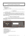
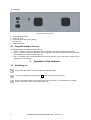
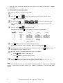
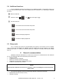
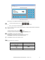
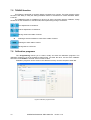
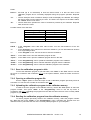
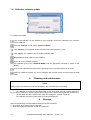
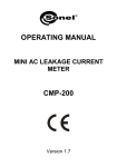
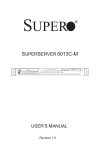
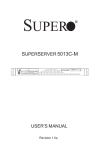
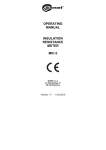
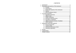
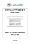
OPERATING MANUAL
RESISTANCE CALIBRATOR
SRP-50k0-5T0
SONEL SA
ul. Wokulskiego 11
58-100 Świdnica, Poland
Version 1.10 14.12.2013
CONTENTS
1
INTRODUCTION ........................................................................................................................................ 4
2
SAFETY...................................................................................................................................................... 4
3
INTENDED USE.......................................................................................................................................... 5
4
DESIGN AND OPERATING PRINCIPLE......................................................................................................... 5
4.1
4.2
5
TERMINALS AND BUTTONS ............................................................................................................................. 5
KEYPAD BACKLIGHT COLOURS ......................................................................................................................... 6
OPERATION OF THE CALIBRATOR ............................................................................................................. 6
5.1
5.2
5.3
5.4
5.5
SWITCHING ON ............................................................................................................................................ 6
MANUAL SETTING OF THE REQUIRED RESISTANCE VALUE ...................................................................................... 7
AUTOMATIC MEASUREMENTS ......................................................................................................................... 8
ADDITIONAL FUNCTIONS ................................................................................................................................ 9
SLEEP MODE................................................................................................................................................ 9
6
GENERAL RECOMMENDATION ................................................................................................................. 9
7
SRP CONTROL SOFTWARE....................................................................................................................... 10
7.1
ABOUT THE SOFTWARE ................................................................................................................................ 10
7.2
FUNCTIONS ............................................................................................................................................... 10
7.3
INSTALLALING AND RUNNING THE SOFTWARE ................................................................................................... 10
7.4
MANUAL MODE ......................................................................................................................................... 10
7.5
CALIBRATION PROGRAMS ............................................................................................................................. 12
7.5.1
Save the calibration program to disc............................................................................................. 13
7.5.2
Opening a calibration program file ............................................................................................... 13
7.5.3
Uploading the calibration program to the calibrator memory ..................................................... 13
7.5.4
Reading the calibration program from the calibrator memory..................................................... 13
7.5.5
Erasing the calibration program in the calibrator memory........................................................... 14
7.6
SERVICE MODE........................................................................................................................................... 14
7.7
TOP MENU ................................................................................................................................................ 14
7.7.1
"File" menu.................................................................................................................................... 14
7.7.2
"Settings" Menu ............................................................................................................................ 15
7.7.3
"Help" menu .................................................................................................................................. 15
7.8
CALIBRATOR SOFTWARE UPDATE ................................................................................................................... 16
8
CLEANING AND MAINTENANCE .............................................................................................................. 16
9
STORAGE ................................................................................................................................................ 16
10
DISMANTLING AND DISPOSAL ............................................................................................................ 17
11
TRANSPORT ........................................................................................................................................ 17
12
CALIBRATOR CHECK ............................................................................................................................ 17
13
TECHNICAL SPECIFICATIONS ............................................................................................................... 17
13.1
13.2
BASIC DATA........................................................................................................................................... 17
ADDITIONAL DATA .................................................................................................................................. 17
14
EQUIPMENT........................................................................................................................................ 17
15
MANUFACTURER ................................................................................................................................ 19
2
OPERATING MANUAL SRP-50k0-5T0
version 1.10
NOTE!
In connection with continuous product improvement and increase of its technical
parameters and performance, there may be slight design changes, not reflected in this
edition of the manual.
NOTE!
Before using, leave the calibrator in normal climatic conditions consistent with the
instrument specifications for at least 12 hours.
NOTE!
When connecting the calibrator to the mains make sure it can be easily disconnected.
NOTE!
Failure to comply with the instructions contained in this manual may result in
electrocution, fire or serious damage of the instrument.
OPERATING MANUAL SRP-50k0-5T0
version 1.10
3
1
Introduction
This Manual contains information on the design and use of the SRP-50k0-5T0 resistance
calibrators, their operating limitations and safety measures when using them. The Manual is intended
for the staff using the calibrators as well as the support personnel.
Symbols shown on the instrument:
Read the manual before using the instrument. Strictly comply with the safety rules
and manufacturer's recommendations.
Alternating current
Operational earthing terminal
Warning, dangerous voltage
2
Safety
NOTE!
Read the manual carefully before using the instrument.
The instrument should be used only by the staff who have received adequate training in
handling electrical equipment.
Connect the calibrator only to the sockets with earthing pins!
NOTE!
Always connect the instrument to the mains using the cable with earthing.
Observe the following rules to avoid accidents or instrument damage:
Use the calibrator solely for the purposes described in this manual,
Before connecting the calibrator to the mains, make sure the power cable is intact,
Store the unit in a dry place with the humidity not exceeding the value given in the manual,
Do not use the calibrator with visible mechanical damage,
When replacing the fuse, make sure that the instrument is disconnected from the mains. The
replacement fuse must conform to the description given in this manual,
• When working with the calibrator, use appropriate test probes.
• Before measurement, make sure the leads are connected to respective measuring terminals.
• Do not apply higher voltage to the terminals than specified in the manual.
•
•
•
•
•
4
OPERATING MANUAL SRP-50k0-5T0
version 1.10
NOTE!
The instrument may be repaired solely by the manufacturer. Tampering with the instrument
may result in electrocution, fire or dangerous accident.
When performing the measurements, the following elements must be isolated from the
workplace:
• live electrical equipment,
• metal structures,
• materials collecting static potential,
• moving people.
Resistance set by the calibrator can be electrically powered by an external direct voltage up to
5000V.
3
Intended use
The calibrator is a source of high resistance, used as a standard in tests of analogue and
digital insulation resistance meters.
The resistance generated by the calibrator can be maintained for a long time under external
direct voltage up to 5000V, provided that the current in the measuring circuit does not exceed 3mA.
The required resistance is set by the user using the calibrator's touch keypad or via an
external PC applications. The required value is set automatically thanks to the switching of a precise
resistance matrix. The controlling processor calculates the required combination of resistors, ensuring
adequate resistance precision.
4
Design and operating principle
The calibrator consists of a two-way matrix of standard resistors with the function of intelligent
resistors' switching. A step-by-step method is used to obtain the required resistance value. The
switching algorithm is controlled by a microprocessor and the current state of the matrix depends on
the resistance value.
4.1 Terminals and buttons
Fig. 1. Front panel of the SRP-50k0-5T0 calibrator
1 – terminals to connect an insulation resistance meter,
2 – operational earthing,
3 – resistance range selection – MΩ,
4 – resistance range selection – GΩ,
5 – resistance range selection – TΩ,
6 – programs switching or activating an additional keyboard,
7 – START the measurement,
8 – STOP the measurement,
9 – decimal comma,
10 – keyboard,
OPERATING MANUAL SRP-50k0-5T0
version 1.10
5
11 - USB port.
Fig. 2 Rear panel of the calibrator
1 – power ON/OFF switch
2 – fuse (F 3.15 А)
3 – socket for the power cable (230V ~),
4 – cooling fans,
5 – earthing terminal.
4.2 Keypad backlight colours
Keyboard backlight is available in three colours:
• Green - calibrator is ready for operation and no resistance is set at the measuring terminals,
• Red - resistance is set at the terminals or a wrong button has been pressed during the operation
(the backlight turns red for a brief moment),
• Blue - confirmation that a keyboard button has been pressed (in case of a correct function). This
signalling can be disabled.
5
Operation of the calibrator
5.1 Switching on
Connect the calibrator to the mains using the supplied cable.
Turn on the calibrator using the switch 1 on the rear panel (see Figure 2).
Connect the tested meter to the measuring circuit (see Figure 3). The calibrator is in standby
mode, no resistance values are set (see Figure 4).
6
OPERATING MANUAL SRP-50k0-5T0
version 1.10
Figure 3 Connecting the meter to the calibrator.
Figure 4 Calibrator display after turning on
5.2 Manual setting of the required resistance value
Start the calibrator. The default range is МΩ.
Select the appropriate range using the buttons 3
4
5
.
Enter the desired resistance value on the keypad 10 (take the selected range into account).
To delete the entered value, use the button 6
To erase the last digit, the display must shown the
appears in the manual resistance setting mode.
symbol (BACKSPACE). This symbol
Press the 7 START to set the required resistance values on the measuring terminals. The word
START disappears from the display and the keypad turns from green to red.
Press the 8 STOP button to end the measurement.
The keypad backlight colour changes from red to green.
Note:
The resistance value on the measuring terminals (after pressing the START button) can be
changed during the measurement procedure). Enter a new value from the keypad and press 7
START. If you do not press 7 START after entering a new value, the previous resistance value will
remain at the calibrator's terminals. A new resistance value can be set on all ranges.
In order to avoid additional unspecified measurement error:
• avoid twisting electrical leads connecting the calibrator with the tested device,
• the calibrator terminals and sockets must be clean,
OPERATING MANUAL SRP-50k0-5T0
version 1.10
7
•
ensure a reliable connection between the test probes of the tested device and the calibrator
terminals.
5.3 Automatic measurements
Start the calibrator. The default range is МΩ.
Press the 6 button
sign will change to
The
Use the buttons 3
to switch the calibrator into the program selection mode.
.
4
to select the required program.
5
After selecting the program, the display shows the name of the program and initial input
voltage.
Press the button 6
to change the mode.
Keep pressing the button 6 to switch between modes as in the table below:
MODE
NUMBER
1
2
3
4
MODE
F1 key
F2 key
F3 key
manual
auto
auto
auto
MΩ
PROGRAM 1
PROGRAM 4
PROGRAM 7
TΩ
PROGRAM 3
PROGRAM 6
PROGRAM 9
5
auto
PROGRAM 10
GΩ
PROGRAM 2
PROGRAM 5
PROGRAM 8
language
selection
-
Back to MODE 1
Press 7 START to activate the selected calibration program.
The calibrator generates a set of resistance values on output terminals 1 .
During this procedure, after measuring a given resistance value, press 7 START to switch
the calibrator to the next resistance value.
The END message is displayed when the program is completed.
Press 8 STOP to select another program
or
Press 7 START to repeat the same program
Pressing 8 STOP at any time during the program execution immediately interrupts the
procedure and returns the calibrator to the program selection mode.
Note:
The calibrator can store up to 10 different calibration procedures. Programs are edited and
installed by means of the included software. The calibrator programming is described later in this
manual.
8
OPERATING MANUAL SRP-50k0-5T0
version 1.10
5.4 Additional functions
A set of additional functions may depend on the calibrator firmware. The firmware version can
be read in the left-hand bottom corner of the display when the calibrator is on. Selecting the individual
functions:
Start the calibrator.
Press the button 6
The
sign will change to
.
Use the buttons to:
Turn off the sound and button beep tones.
Turn on the sound and button beep tones.
Reduce the display brightness.
Increase the display brightness.
5.5 Sleep mode
If for 10 minutes (this period is programmable) the keypad is not touched or the PC software
does not send any commands, the calibrator goes into sleep mode and the display is off. Briefly
pressing any button or a software command restores the calibrator to standby mode and the display
turns on.
6
General recommendation
Calibrator technical maintenance is carried out to ensure its full effectiveness and readiness
for use. The following shall be checked during the maintenance:
•
integrity of seals,
•
completeness of the calibrator
•
absence of external mechanical damage,
•
cleanliness of connectors, sockets and terminals,
•
condition of test leads and contacts.
NOTE!
Never put the calibrator on the front or rear panel, as this can damage the control and power
cable socket.
•
•
The users are allowed to perform the following calibrator maintenance activities:
replacement of a blown fuse (F 3.15 A),
calibrator cleaning.
OPERATING MANUAL SRP-50k0-5T0
version 1.10
9
NOTE!
Before replacing the fuse disconnect the calibrator from the mains.
Any other maintenance activities must be performed solely by the SONEL S.A. Service Dept.
7
SRP Control Software
7.1 About the software
The SRP software is used to connect the SRP-50k0-5T0 calibrator with a PC. The program is
easy to use and is a useful tool in the process of testing the devices by means of the calibrator. The
calibrator should be connected to a computer via the USB port.
7.2 Functions
•
•
•
•
•
•
remote control of the calibrator,
create and save the automatic programs to check the tested devices,
set the keypad lock and time to sleep mode,
change the display brightness and keypad tones,
software language selection,
calibrator software update from the PC via the USB interface.
7.3 Installing and running the software
The SRP software does not need to be installed on your computer. Run the SRP.exe from the
hard disk or other storage medium. Synchronization of the current calibration status with the software
will begin Immediately after running the program. After starting, the program is ready to work.
Minimum PC requirements:
• Windows XP or later,
• 1 GHz processor,
• 512 MB memory,
• free USB port, keyboard, mouse, monitor.
7.4 Manual mode
The program allows you to set the required resistance value, using the virtual keyboard or
using a standard PC keyboard. To do this:
Connect the calibrator to your computer via a USB cable.
Start the calibrator and run the program.
Go to the MANUAL tab.
10
OPERATING MANUAL SRP-50k0-5T0
version 1.10
Figure 5 Manual mode screen
After turning on, the calibrator automatically goes to the MΩ range.
To set the required range, use the
buttons
or
the F1, F2, F3 keys on the PC keyboard.
Enter the resistance value using the numeric keypad or computer keyboard (take the appropriate
range into account).
To delete the entered value, press the
The display information field shows the
button.
(BACKSPACE) symbol.
Press START to set the typed resistance value.
Resistance at the terminals can be changed freely in all ranges.
Press START to set the newly entered resistance value.
Press STOP to disconnect the resistance value.
Note:
List of common buttons (PC / calibrator):
Calibrator keypad
Computer keyboard
0 – 9, ",”
0 – 9, ”,”
F1 F2 F3
SHIFT
START
OPERATING MANUAL SRP-50k0-5T0
ENTER
version 1.10
11
7.5 TUNING function
This feature is designed to smoothly adjust a resistance up or down. The main objective of this
function is the ability to verify the analog insulation testers in accordance to russian standard: GOST
8.409-81.
The TUNING function is available only when is an active connection with the calibrator. Firstly
should be set the resistance in manual mode, before performing tuning of resistance.
Fine adjustment of resistance.
Coarse adjustment of resistance.
Saving result to the table of values.
X
Deleting a selected resistance value from a table of values.
Deleting an entire table of values.
Saving table to a CSV file.
7.6 Calibration programs
The “Programming” allows you to create, modify and save the calibration programs. The
calibration program is a set of resistance values which, one after the other, are set at the calibrator
terminals. Press START to activate each successive value.
Calibration programs can be stored in the calibrator memory and the computer's hard disk.
Figure 6 Calibration programs screen.
12
OPERATING MANUAL SRP-50k0-5T0
version 1.10
Fields:
Device – text field (up to 10 characters) to enter the device name. It is also the name of the
calibration program and is constantly displayed during the program operation. Required
field.
"U"
– numeric field (the value is limited to 5000) to enter and display the calibrator test voltage;
the field is used to enter values by the user. The field is not required. If the field is blank,
the ”Add U” button is not active.
"R"
– numeric field which specifies the value of resistance provided by the calibrator. Required
field; at least one value.
Possible values of the “R” field:
Resistance range
[Ω]
50…950k
0.05 ... 999.95 M
0.001 ... 999.999 G
0.0001 ... 5.0000 T
Resolution
[Ω]
50k
0.05 M
0,001G
0.0001 T
Buttons:
Add U – in the “Program” menu: add extra value menus. You can add maximum of five "U”
menus.
"+”
– in the “Program” menu: add a line to enter the resistance; you can add maximum 59 lines
for a single voltage value.
"-"
– in the ”Program” menu: remove the line to enter the resistance.
"Save" – in the “File” menu: save the calibration program to disk.
"Open”– in the “File” menu: open the calibration program file from the disk.
"Save" – in the “Programming” menu: upload the calibration program to the calibrator.
"Read" – in the “Programming” menu: read the calibration program from the calibrator.
"Erase”– in the “Programming” menu: erase the calibration program in the calibrator.
7.6.1 Save the calibration program to disk
To save the calibration program to your hard disk, click “Save” in the “File” menu or use the
top menu in accordance with subsection 7.7.1. In the opened window, select the folder and file for
saving.
7.6.2 Opening a calibration program file
Use the “Open” option to select and open to edit a calibration program previously saved to
hard disk. You can also use a toolbar in accordance with 7.7.1.
7.6.3 Uploading the calibration program to the calibrator memory
In order to save the program in the calibrator memory, use the P1…P10 options to select the
program number. Then press “Save” in the “Programming” menu or use the top menu in
accordance with 7.7.1. Uploading the program from the disk will cause the loss of the currently edited
program on your computer.
7.6.4 Reading the calibration program from the calibrator memory
To read a program previously stored in the calibrator memory, select the program number
P1…P10 and then press “Read” in the “Programming” menu. Uploading the program from the
calibrator memory will cause the loss of the currently edited program on your computer.
OPERATING MANUAL SRP-50k0-5T0
version 1.10
13
7.6.5 Erasing the calibration program in the calibrator memory
To erase the stored program, select its number P1…P10, and then press “Erase” in the
“Programming” menu. Deletion of the program should be further confirmed in the confirmation
window.
7.7 Service mode
The “Service” tab is used to enter the calibrator service mode. The service mode is password
protected.
NOTE!
The service mode is solely for diagnostic purposes at the manufacturer's service department.
7.8 Top menu
7.8.1 "File" menu
Figure 7 "File" menu.
Open
Save
– open the calibration program file.
– save the calibration program to the computer disk
Figure 8 Uploading the calibration program to the calibrator
Programming – upload the program to the calibrator memory under a selected number. This option
is available only if the “Programming” tab is active.
Exit
– exit the SRP program.
14
OPERATING MANUAL SRP-50k0-5T0
version 1.10
7.8.2 "Settings" Menu
Figure 9 "Settings" menu
Language
– software language selection. Available languages: Russian and English.
Keyboard lock – calibrator keylock. When the keypad is locked, the calibrator is controlled from the
computer only.
Figure 10 Locking the keypad.
Sleep mode
– setting the time to sleep mode. To exit the sleep mode, press any button on the
calibrator keypad or in the SRP software.
Figure 11 Setting the time to sleep mode.
Firmware update – updating the calibrator firmware. Updates can be downloaded from the
manufacturer's website.
7.8.3 "Help" menu
Figure 13 "Help" menu
Version
– displays: calibrator firmware version, computer software version, calibrator serial
number and type.
Open help – display the SRP software help.
OPERATING MANUAL SRP-50k0-5T0
version 1.10
15
7.9 Calibrator software update
Figure 12 Calibrator firmware update.
To update the firmware:
Turn on the calibrator, run the software on your computer, connect the calibrator to the computer
via the USB port.
From the "Settings" menu, select "Firmware update".
Click "Browse" in the opened window and then select the update file (*.sfw).
Click "Apply"; the calibrator goes to update readiness state.
Disconnect the USB cable from the calibrator.
Press ”5” on the calibrator keypad.
The calibrator goes to the "UPDATE MODE" and the appropriate message is shown on the
display.
Connect the USB cable and wait until the update process is complete (about 30 seconds).
When the update is finished, turn off the calibrator with the main switch and disconnect the USB
cable.
8
Cleaning and maintenance
NOTE!
Apply solely the maintenance methods specified by the manufacturer in this manual.
The calibrator enclosure may be cleaned with a soft, damp cloth using all-purpose detergents.
Do not use any solvents or cleaning agents which might scratch the enclosure (powders, pastes, etc.).
The test leads should be cleaned with water and detergents, and then wiped dry.
The calibrator electronic system does not require maintenance.
9
Storage
Observe the following recommendations when storing the instrument:
• Disconnect all the leads from the calibrator.
• Clean thoroughly the calibrator and all its accessories.
16
OPERATING MANUAL SRP-50k0-5T0
version 1.10
• Wind the long test leads onto the reels.
10 Dismantling and Disposal
Used electrical and electronic equipment should be collected selectively, i.e. it must not be
placed with another kinds of waste.
Used electronic equipment should be sent to a collection point in accordance with the Used
Electrical and Electronic Equipment Act.
Do not dismantle any elements before the equipment is sent to a collection point.
Observe the local regulations concerning disposal of packagings and used batteries.
11 Transport
In its original packaging, the calibrator can be transported using all modes of transport. The
transport distance is not limited.
During transport, the instrument must be protected against precipitation and ingress of dust.
Handle with care.
12 Calibrator check
It is advised to check the calibrator every 12 months.
13 Technical specifications
13.1 Basic data
Resistance range [Ω]
Resolution [Ω]
0.05 ... 999.95 M
0.001 ... 999.999 G
0.0001 ... 5.0000 T
0.05 M
0.001 G
0.0001 T
Measurement
uncertainty
1.5%
1.5%
1.5%
13.2 Additional data
•
•
•
•
•
•
•
•
•
•
•
•
supply voltage
maximum power consumption:
maximum current in the measuring circuit:
maximum operating voltage:
long-term stability of resistors:
max. operating altitude:
dimensions
weight:
operating temperature range:
relative humidity:
storage temperature range in the original packaging:
at relative humidity <80%
at relative humidity from 50% to 80%
at relative humidity <80%
storage temperature range without packaging:
at relative humidity <80%
100 ... 240V AC (50/60Hz)
75VА
3mА
5000V DC
<1%
2000m
540 х 450 х 200mm
approx. 15kg
+10…+30ºС
25…60%
-20…+31ºС
-20…+40ºС
-20…+60ºС
+10…+30ºС
14 Equipment
•
•
•
calibrator SRP-50k0-5T0 - 1 pc
power cable - 1 pc
CD with the SRP software - 1 pc
OPERATING MANUAL SRP-50k0-5T0
version 1.10
17
•
•
•
•
•
18
1.8 m test lead with 5kV banana plugs, blue – 1 pc
1.8 m test lead with 5kV banana plugs, red – 1 pc
2.2 m shield cable with banana plugs, black – 1 pc
operating manual – 1 pc
calibration certificate – 1 pc
OPERATING MANUAL SRP-50k0-5T0
version 1.10
15 Manufacturer
Manufacturer and provider of warranty and post-warranty service:
SONEL SA
ul. Wokulskiego 11
58-100 Swidnica, Poland
Tel: (+48 74) 858 38 60 (Sales)
fax (+48 74) 858 38 09
e-mail: [email protected]
internet: www.sonel.pl
NOTE
Service repairs must be performed solely by the manufacturer.
Made in Russia.
OPERATING MANUAL SRP-50k0-5T0
version 1.10
19