1
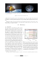
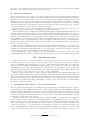
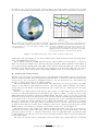
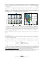
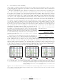
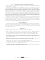
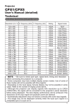
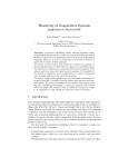
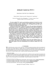
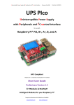
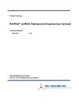
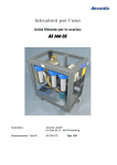
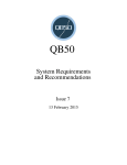
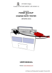
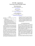
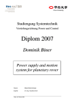
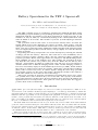
Battery Operations for the TET–1 Spacecraft
Kay Müller∗ and Arvind Kumar Balan∗∗
Deutsches Zentrum für Luft- und Raumfahrt e. V., German Aerospace Center
Münchener Straße 20, 82234 Weßling, Germany
The TET–1 satellite serves as a technology demonstrator within the On-Orbit Verification (OOV) program with the goal of providing German space companies and research
institutions with the opportunity to test their equipment on actual spacecraft. It was
launched on July 22, 2012, by a Russian Soyuz/Fregat into a Sun-synchronous orbit
with an LTAN of 11:27 UTC. The satellite is powered by nickel-hydrogen batteries
during eclipse.
The operations team became aware of several issues shortly before and after the
launch which created some challenges for battery operation. Some battery cells had
undergone reversal prior to launch which seems to have created an imbalance between
them. Also, the overall temperature within the satellite and that of the batteries turned
out to be higher than predicted and the battery voltage slightly exceeded the limit for
payload operations.
Regulating the battery temperature was at first attempted by lowering the amount
of charge put into the battery. However, this could not be done indefinitely due to
worries of battery damage (memory effect) and the constricted charge available for
payload operations. Hence, other approaches were employed. The Sun Pointing Rotate
Mode (SPRM) was one of the methods used. The satellite was reoriented in such a
way that the bus radiator was pointed away from the Earth and the Sun by more
than 90◦ . Consequently, its ability to radiate heat away into deep space was improved.
Another method was a different charging scheme called “ratchet charging”, known to
have been successfully employed on the Hubble Space Telescope (HST). In this method
the battery is charged more than once during a Sun phase and the End–of–Charge
(EoC) value is raised every week. A software update during the latter stage provided
more flexible control over the solar panel strings, allowing the satellite to fly without a
pitch offset which was used earlier to lower the voltage.
This paper describes in detail the circumstances in which these issues arose, wherever possible their causes and how they were dealt with. The capacity of the TET–1
spacecraft’s batteries is found to have increased from 12 Ah to about 14 Ah without any
significant increase in temperature. Data gained at a later point in time also suggest a
positive effect of the reconditioning.
I.
Introduction
he TET–1 spacecraft (shown in Figure 1a) serves as a technology demonstrator (“TET” is an abT
breviation of the German “Technologieerprobungsträger”, or technology demonstrator) within the
On–Orbit Verification (OOV) program with the goal of providing German space companies and research
institutes with the opportunity to test and qualify their equipment on actual spacecraft. It is the first
satellite of that program and was launched on July 22, 2012 into a Sun–synchronous orbit with a local
time of ascending node (LTAN) of 11:27 UTC. This means there are eclipses in every orbit throughout
the year, a circumstance that necessitates the frequent use of the battery.
The OOV mission was scheduled to last one year. At the end of October 2013 all the desired mission
goals were achieved and the OOV part of the mission officially ended. Since November 2013 the satellite
is now in the validation phase of the Firebird mission whose goal it is to take pictures of wildfires using
an infrared camera. In the future, TET will be joined by another spacecraft based on the same bus
called BIROS which will allow the Firebird mission to use a constellation of two satellites.
Three solar panels provide the electrical power. Two of which are located on the ±x-sides and were
deployed after launch so that they are now in the same plane as the center panel. For the side panels
∗ PTS
∗∗ PTS
Team Lead, German Space Operations Center, Oberpfaffenhofen, 82234 Wessling, Germany, [email protected]
Engineer, German Space Operations Center, Oberpfaffenhofen, 82234 Wessling, Germany, [email protected]
1 of 7
SpaceOps 2014; Pasadena, California – May 5 - 9
(a) The +y direction is the vector normal to the bus radia- (b) Sun–synchronous orbit with a local time of ascending
tor. −z is normal to the solar panels and +z is the direction node (LTAN) of 11:27 UTC.
of the infrared camera.
Figure 1: The TET–1 spacecraft and its orbit.
a shunt function is provided, for the center panel there is not. The power output of the center panel
is designed to be roughly equivalent to the power needs of the spacecraft bus. In total, there are 17+1
solar strings. Seventeen regular bus strings plus one payload string which is usually used by the bus as
well.
Shunting the strings of the side panels (and the payload string) is the means of battery charge control.
It is possible to select specifically which of the strings shall be shunted when the battery is full. The
default setting is to shunt all of them.
II.
A.
The Battery
Description
Current [A],Charge [Ah]
The satellite uses a Nickel–Hydrogen (Ni-H2 ) battery
with eight common pressure vessels (CPVs) of the type
15
RNHC-12-3 by Eagle Picher with two cells each. 6 The
cells of this type of battery need to be placed in pres10
sure vessels since charging them releases hydrogen gas
which has to be contained. Charging a Ni-H2 battery is
5
endothermic, the discharge process is exothermic. The
rated capacity is 12 Ah but the actual capacity is somewhat higher since the usual discharge current on board
0
is lower than the 6 A used in the rating. This was
also seen on the BIRD satellite which used the same
-5
cells. The CPVs are arranged in two stacks of four CPVs
each. In each stack, the temperature and strain of one
-10
CPV are measured. The pressure can be calculated
05:30 05:45 06:00 06:15 06:30 06:45 07:00 07:15 07:30
from the strain which, combined with the temperature,
Charge
Battery Current
calibrated Charge
Solar Panel Current
yields the charge. It is important that the pressure does
not become too high. The temperature is therefore included for the shunt function. That way, a metric for Figure 2: The battery charge (electrical and “calithe actual pressure (“calibrated” charge in Figure 2) is brated”) is shown with the battery and solar currents.
provided irrespective of what causes it, temperature or The two horizontal red lines represent the commanded
end–of–charge (EoC) level (top) and the safe mode level
charge. When the calibrated charge reaches a certain (bottom). A positive battery current charges the batlevel (End–of–Charge (EoC) level) the solar strings of tery, a negative one discharges it. The current for the
the side panels are shunted. This also means that when battery is provided by the solar panels. When the calthe battery temperature is high, the electrical charge ibrated charge reaches the EoC level, the specified solar strings are shunted (red background). During the
at the point of shunting is comparatively low because eclipse (gray background), the battery is discharged and
the shunting process happens earlier. The shunts are at a set percentage of the maximum charge the shunts
charge process shown here is for
opened again once the battery charge drops below a are opened again. The
a pitch offset of 30◦ . (See Section III.C.)
certain percentage of the maximum. See Figure 2 for
an example of the charge process.
The trigger values at which the shunts are opened or closed can be set from the ground. In order to
2 of 7
SpaceOps 2014; Pasadena, California – May 5 - 9
prevent too deep a discharge, the charge and the voltage of the battery are both being monitored. When
they drop below certain set points, a safe mode is triggered.
B.
Operational Challenges
The operations team became aware of the fact that the battery had been unintentionally discharged
deeply at least twice prior to launch; once during a simulation and again during the launch preparation.
This had led to the voltage reversal of two cells and created worries about the battery status. Because
TET was a secondary payload and the launch date was fixed, it would not have been possible to exchange
it. During the days leading up to the launch the team present at the launch site attempted to recondition
the battery. This went on up until twelve hours before launch but afterwards the spacecraft could not
be monitored anymore and the battery could not be charged.
However, the first contact after launch showed a satisfactory battery charge level. The side solar
panels were deployed shortly after, providing more current for the battery.
Once it was fully charged telemetry showed that its temperature was significantly higher than expected
and that the bus voltage was about 1 V above its desired maximum. Although not expected to pose an
actual problem, the voltage was higher than the payload support system was qualified for and therefore
presented a risk. The impact of the temperature is more significant since the battery temperature has
a large influence on its life expectancy. The issue is magnified when the payloads are in use since they
naturally increase the overall temperature of the spacecraft and require the battery to be discharged more
during eclipses. This also raises the temperature somewhat due to exothermic nature of the discharge
process of a Ni-H2 battery.
There was some confusion as to why the temperature was so high in the first place. A review revealed
that the bus radiator was effectively too small. The payloads were not in use during a test in the solar
chamber and the measured temperatures were too low. The radiator was therefore deemed too large and
was consequently partly covered in MLI to reduce its effectiveness.
Also, the discharge of the battery prior to launch likely caused an imbalance of the cells. This,
combined with the radiator issue, caused the battery temperature to be at least 5◦ C higher than expected.
III.
Operational Actions
When a spacecraft is too warm, the influx or generation of heat needs to be reduced or the effectiveness of the heat rejection has to be increased. The battery temperature had been at about 20◦ C
when the maximum desired temperature was 15◦ C 8 . This desired temperature has been a driver for
battery operations throughout the mission. Consequently, payload operations on TET were suspended
intermittently for one day of the week in order to decrease the load. The amount of time spent in the
thermally unfavorable Earth–Pointing Mode was also reduced as much as possible. This worked because
it takes about two or three days for the spacecraft to reach “equilibrium”.
However, other measures were also taken. Another nominal attitude mode was flown which improved
the radiator’s ability to emit heat (see Subsection III.A). An attempt at improving the battery’s efficiency
was made by invoking “ratchet charging” and increasing the end–of–charge level (see Subsection III.B).
The spacecraft was rotated—and thereby the current from the solar panels decreased—in order to reduce
the bus voltage (see Subsection III.C). And finally, a software update allowed for more overall flexibility
in battery operations (see III.D).
A.
Sun-Pointing Rotate Mode — a more suitable attitude
Since the radiator was responsible for the high battery temperatures an attempt was made to improve
its effectiveness. In the nominal attitude mode—called the Sun Pointing Fix Mode (SPFM)—TET has
an inertial attitude with the vector normal to the solar panels pointing towards the sun and the +x axis
pointing parallel to the Earth’s rotational axis (North). In its orbit (see Figure 1b) and using the SPFM,
the radiator partially sees the Earth which has a negative effect on its temperature and thus its ability
to radiate heat away from the spacecraft.
Another attitude mode—the Sun–Pointing Rotate Mode (SPRM) 6,7 —was intended as contingency
mode for such a scenario. This mode is somewhat similar to the SPFM in that the vector normal to
the solar panels points towards the Sun. But instead of being completely inertially fix throughout the
entire orbit, the spacecraft is rotated 180◦ about the z-axis at every equator crossing so that the vector
normal to the radiator (+y) points parallel to the Earth’s rotational axis. It points North when over
the Northern hemisphere and South when over the Southern hemisphere (see Figure 3a). Close to the
equator the radiator surface still sees the Earth but above the North and South pole it does not see
3 of 7
SpaceOps 2014; Pasadena, California – May 5 - 9
the Earth at all. At every point in the orbit the angle between the radiator’s normal vector and the
vectors towards the Sun and the Earth is greater than 90 degrees. The effect on the radiator and battery
14
N
12
Temperature [° C]
10
8
6
4
2
0
tor
Equa
-2
12:00
18:00
00:00
06:00
Battery Temp.
Radiator Temp. 1
(a) Generally, the bus radiator is pointed towards the
North or the South depending on which side of the equator
the spacecraft is on. At each equator crossing a 180◦
rotation takes place.
12:00
18:00
00:00
06:00
12:00
Radiator Temp. 2
(b) Battery and Radiator Temperature during SPFM and
SPRM (gray area). All other parameters such as EoC level
and power consumption were equal in both modes. It is
also apparent that the temperature of the radiator is very
different for the two thermistors located there. Note that
no payload operations are ongoing at the shown time.
Figure 3: The SPRM and its effect on the radiator and battery temperatures.
temperature is shown in Figure 3b. No other parameters were changed and the reduction in temperature
due to the SPRM was about 4◦ C.
The downside of using the SPRM was that the star cameras (which point towards the −y direction)
did not see any stars for much of the orbit since they were partially pointed towards the earth. When at
one point the Inertial Measurement Unit (IMU) failed, the spacecraft had much less accurate attitude
information at its disposal which caused the reaction wheels to be in heavy use. This led to the loss of
one of the wheels 5 and it was decided to suspend the SPRM in order to not risk losing another one.
B.
Treating the battery better
The EoC level was lowered as an initial response to the high temperatures during payload operations and
when the battery was fully charged. Experience had shown this to be effective to reduce the temperature.
It was, however, also clear that not charging the battery to its capacity was not a good idea in the long
run due to adverse effects such as the “Memory Effect”.
The battery itself also did not perform ideally. The temperature rose noticeably when it was fully
charged. It was suspected that unbalanced battery cells caused this. These individual cells would be
already full and consequently overcharged when the rest of them were not. This may have raised the
temperature.
Therefore, the satellite support team came up with a plan to recondition the battery. The effort was
based on reconditioning methods used on the Hubble Space Telescope (HST) 2 and was also tested on the
TET engineering model where it showed promising results. The basic course of action was to increase
the EoC level every week by 0.2 Ah and increase the parameter which determines when the shunts would
open again from 95 to 98 percent of the EoC value. With the help of payloads running this method was
supposed to mimic the “ratchet charging” done on HST. The intention was to deliberately overcharge
the suspected unbalanced cells and to thereby bring them closer to the rest. The battery was charged
up until the EoC value was reached, then a discharge of the battery caused by payloads would open the
shunts again for a second phase of charging. An example for this can be seen in Figure 4a.
The interpretation of the results is not entirely straight forward since the payload operations are
distributed over certain orbits of the days of the week. The same day of the week would see the same
payloads operated. In order to assess the effectiveness of the reconditioning effort, representative days
on which similar payloads were active were selected and the measured charge was plotted against the
battery temperature.
The expected outcome of the reconditioning was that the bulk of the points would move towards the
4 of 7
SpaceOps 2014; Pasadena, California – May 5 - 9
top left, i.e. to higher charge levels and lower temperature. This did indeed happen as can be seen in
Figure 4b.a During each week, after the EoC value had been set higher, the battery temperature rose a
bit. The fact that the temperature did not rise afterwards but fell can be seen as evidence for an effective
reconditioning.
During the later parts of the OOV mission temperatures were again somewhat higher (15◦ C at an EoC
of 14.2 Ah) since the thermally more efficient SPRM was not used anymore.b On the other hand, payload
operations were going on much more smoothly and uninterrupted and thus, that period represents a
better metric because a possible long term trend is more likely to be included. The temperature was
not higher than at the beginning of the reconditioning while the battery was charged significantly more.
This suggests that the reconditioning did indeed have a positive effect.
Battery Voltage
13
12
11
Charge [Ah]
Current [A], Charge [Ah]
Voltage [V]
24.5
24
23.5
23
22.5
22
21.5
21
20.5
15
10
9
10
8
5
1 week later, 14.4Ah
2 weeks later, 14.2Ah
1 week later, 13.8Ah
3 weeks later, 13.6Ah
1 week later, 13Ah
3 weeks later, 12.8Ah
start, 12Ah
time
0
7
-5
-10
14:00
14:15
14:30
14:45
Charge
calibrated Charge
15:00
15:15
15:30
15:45
16:00
6
10
Battery Current
Solar Panel Current
12
14
16
18
20
22
24
Temperature [° C]
(a) Example of the the charging method similar to the
one performed on the Hubble Space Telescope. The battery is fully charged. Then, a payload is in use, drawing
enough charge from the battery to enable the charging process again. In this example this happens twice in the same
Sun phase. The end–of–charge level is increased approximately each week for a period of time.
(b) Battery charge plotted against the battery temperature for selected days during the reconditioning period.
The days were selected for their stability and distance from
other disturbances in order to be able to compare the data.
The EoC values were raised each week. While this happens
there is an overall trend towards lower temperature.
Figure 4: Reconditioning of the Ni-H2 battery using an approach reminiscent of the one used on the Hubble Space
Telescope.
C.
Voltage
The voltage issue mentioned in Subsection II.B was dealt with in two different ways, one described here,
the other in the next subsection.
During the charge process, the voltage is higher than during the discharge process because the voltage
across the internal resistance of the battery is added to the generated Electromotive Force (EMF). For
the same state of charge, the voltage of the battery thus differs depending on whether it is charged or
discharged at that time (see equations (1) and (2).)
Ucharge
=
EM F + Icharge · Ri
(1)
Udischarge
=
EM F − Idischarge · Ri
(2)
This also means the battery voltage during charging can be lowered somewhat by reducing the current
with which it is charged. Exactly that was achieved by rotating the spacecraft 30◦ about the pitch axis
(y). The battery charge current is determined by how much the solar panel provides (and how much is
used by the spacecraft and the payloads). Rotating away from the Sun therefore reduced the battery
charge current and thus the voltage. The reduction of the voltage is about 0.2 – 0.3 V.
a During parts of the misson the temperature measurement was skewed by unphysical spikes. This can also be seen in
Figure 4b. The unphysical values are the smaller bulk to the right best seen in the data points at the very top.
b It was used throughout the entire reconditioning period.
5 of 7
SpaceOps 2014; Pasadena, California – May 5 - 9
D.
New software, more flexibility
15
15
10
10
10
5
0
-5
-10
06:30
Current [A], Charge [Ah]
15
Current [A], Charge [Ah]
Current [A], Charge [Ah]
After a number of additional desired features had been compiled it was decided there would be a software
update in the first half of 2013. The opportunity to change the software was used to improve the situation
with the pitch offset as well.
The goal of reducing the charge current by rotating the spacecraft as described above had the downside of also reducing the current produced by experimental payload solar cells. The manufacturers of
those cells, however, wanted to have data gathered without any such offset. This could only be achieved
by finding a way of flying the spacecraft without offset but at the same time reducing the charge current
of the battery. The solution was to define another shunt mask which provided additional functionality
(see Table 1). The original mask defined which strings would be shunted when the battery was fully
charged. The new mask would define which strings are continuously disabled, so that the number of
strings used was reduced, mimicking the reduced input current at the 30◦ offset. The current was in
fact reduced even more than was the case then. But this led to another constraint. Usually, plenty
of power was available but with the reduced current that margin became smaller. During a test campaign validating the infrared camera it was found that in rare cases—such as several images taken in
short order—the battery charge might reach the safe mode limit. This did not actually happen but
was a possibility and a direct consequence of the reduced charge current set by the new shunt mask.
Although the new shunt mask had “caused” the problem it was also
the solution. Whenever power demanding payloads were active Table 1: Number of solar strings available
the number of solar strings available could be increased and then in the different states.
reduced again afterwards. This increased the power margin again
which helped charge the battery faster. This can be seen in Figure
Solar Strings when:
5b. The nominal charge current is now about 4 A (Figure 5a) but
unshunted shunted
is increased to about 7 A in the orbits where power consuming
original:
17+1
5
payload operations occur.
In general, the new shunt mask provided more flexibility for
new:
12+1
5
the battery charge process. This was useful for implementing an
approach that was based on experience on the Grace mission 1,4 and attempted to optimize the charge
profile. When the state of charge is low, the charge current should be relatively high. It should be
lower towards the end of the charge process. The scheme was implemented on Grace and is also in line
with the results obtained by Hartley 3 who determined that a low–high–low charge profile causes less cell
damage than a profile of constant charge current. A similar scheme was also tested on TET (see Figure
5c and compare to Figure 5a) over six orbits but no immediate effect could be observed. The ability to
implement alternate schemes in the future is nonetheless an important asset.
5
0
-5
06:45
07:00
07:15
Charge
calibrated Charge
07:30
07:45
08:00
08:15
Battery Current
Solar Panel Current
08:30
-10
01:45
5
0
-5
02:00
02:15
02:30
02:45
Charge
calibrated Charge
03:00
03:15
03:30
-10
02:00
03:45
Battery Current
Solar Panel Current
(a) Default charge current profile and (b) The new shunt mask was used to
the corresponding charge. Five strings adapt the number of solar strings in use
are removed during the charge process. while a payload is running. The payload
discharges the battery far enough to disable the shunting and then uses all of the
strings to charge.
02:15
02:30
02:45
Charge
calibrated Charge
03:00
03:15
03:30
03:45
04:00
Battery Current
Solar Panel Current
(c) Test of an alternating charging
scheme which causes a high charge current when the battery is at a low state–
of–charge and a low current towards the
end of the charge process with a pause
in–between.
Figure 5: The new shunt mask allowed for more flexibility in the battery charging scheme. In 5a, the now used default is
seen. 5b shows a variation with all the strings used during payload operations and 5c shows a test of an alternate charging
scheme using the new shunt mask.
6 of 7
SpaceOps 2014; Pasadena, California – May 5 - 9
IV.
Conclusions, Outlook and Recommendations
Although unexpectedly confronted with high battery temperatures after launch, the OOV mission
could successfully be completed.
Currently, the Firebird mission is prepared with most of the focus on the infrared camera. The
bottleneck with regards to the execution of payload operations will be the ability to downlink the infrared
pictures. Only as many pictures will be taken as the downlink capacity permits. Power is no constraint.
In case the temperature becomes an issue again, additional actions could be taken by switching off
units such as the star cameras or the magnetic coil system for certain periods. The star cameras had
already been switched off for a portion of the orbit relatively early in the mission. This was effective
temperature wise (about 2◦ C). However, since the Inertial Measurement Unit (IMU) was then the only
source of accurate attitude information and that unit had failed several times throughout the mission it
was decided to not continue this course of action. The software update had essentially fixed the IMU
issue, though 5 , and therefore the approach could be attempted again. The attitude requirements for the
infrared camera will need to be taken into account, though.
Building on the experience gained from operating Grace would also be beneficial. At the moment,
the battery treatment on that mission is continuously optimized. Although the rationale behind the
treatment is understood the data necessary to do the same on TET is not available. If this changes in
the future a similar optimization could possibly be performed. Implementing the Grace treatment much
earlier in its life on TET could significantly extend its life expectancy.
Acknowledgments
The authors would like to thank Jacobus Herman and Markus Hobsch for their helpful comments. Sebastian Löw carefully read the manuscript. Ab Davis provided his insight into the Grace battery charging
scheme. Juliane von Geisau provided Figure 3a. Figure 1a was created by DLR/Astrofeinwerktechnik
and modified by the authors.
References
1
Keith B. Chin and Ab Davis. Internal Communication, 2013. JPL and CSR.
2
Stephen J. Gentz. Technical Consultation of the Hubble Space Telescope (HST) Nickel Hydrogen
Battery. (NASA Engineering and Safety Center Consultation Position Paper RP-04-08), 2004.
3
Tom Hartley. Optimal Battery Charging for Damage Mitigation. (Patent US–7489107B2), 2009.
4
Jacobus Herman, Ab Davis, Keith B. Chin, Markus Kinzler, Sina Scholz, and Michael Steinhoff. Life
with a weak Heart — Prolonging the Grace Mission despite degraded Batteries. In SpaceOps Conference,
Stockholm, Sweden, 2012.
5
Markus Hobsch, Sebastian Löw, and Jacobus Herman. Attitude Control in TET–1 - Experiences of
the First Year of Operations. In these proceedings, Pasadena, California, May 2014.
6
A. Hönle. TET-1 Space Segment User Manual. (TET-KTH-UM-0002), 2011.
7
Sebastian Löw, Jacobus Herman, and Daniel Schulze. Modes and More — Finding the Right Attitude
for TET. In SpaceOps Conference, Stockholm, Sweden, 2012.
8
Lawrence H. Thaller and Albert H. Zimmerman. Overview of the Design, Development, and Application
of Nickel-Hydrogen Batteries. (NASA/TP—2003-211905), 2003.
7 of 7
SpaceOps 2014; Pasadena, California – May 5 - 9