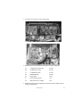
1
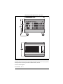
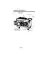
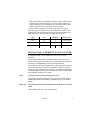
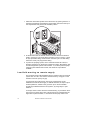
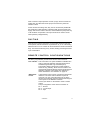
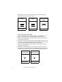
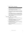
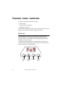
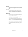
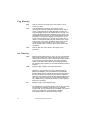
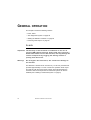
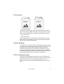
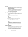
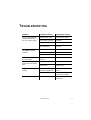
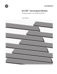
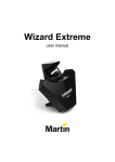
Heavy Fog
Glaciator
X-Stream
user manual
Measurements are expressed in millimeters.
866
600
744
638
© 2004 Martin Professional A/S, Denmark.
All rights reserved. No part of this manual may be reproduced, in any form or by any means,
without permission in writing from Martin Professional A/S, Denmark.
Printed in United Kingdom.
P/N 35010021, Rev. B
Introduction . . . . . . . . . . . . . . . . . . . . . . . . . . . . . . . . . . . . . . . .4
Features . . . . . . . . . . . . . . . . . . . . . . . . . . . . . . . . . . . . . . . . . . . . . . . . . . . . .
Safety information . . . . . . . . . . . . . . . . . . . . . . . . . . . . . . . . . . . . . . . . . . . . . .
Unpacking . . . . . . . . . . . . . . . . . . . . . . . . . . . . . . . . . . . . . . . . . . . . . . . . . . . .
Product overview . . . . . . . . . . . . . . . . . . . . . . . . . . . . . . . . . . . . . . . . . . . . . . .
4
5
6
7
Installation . . . . . . . . . . . . . . . . . . . . . . . . . . . . . . . . . . . . . . . . .8
Fixture location . . . . . . . . . . . . . . . . . . . . . . . . . . . . . . . . . . . . . . . . . . . . . . . . 8
AC power . . . . . . . . . . . . . . . . . . . . . . . . . . . . . . . . . . . . . . . . . . . . . . . . . . . . 8
Installing a remote fluid system . . . . . . . . . . . . . . . . . . . . . . . . . . . . . . . . . . . . 9
Ducting . . . . . . . . . . . . . . . . . . . . . . . . . . . . . . . . . . . . . . . . . . . . . . . . . . . . . 11
Remote control configurations . . . . . . . . . . . . . . . . . . . . . . . . . . . . . . . . . . . 11
DMX-512 setup & control . . . . . . . . . . . . . . . . . . . . . . . . . . . .13
Data connection for DMX operation . . . . . . . . . . . . . . . . . . . . . . . . . . . . . . .
DMX control address . . . . . . . . . . . . . . . . . . . . . . . . . . . . . . . . . . . . . . . . . . .
DMX operation . . . . . . . . . . . . . . . . . . . . . . . . . . . . . . . . . . . . . . . . . . . . . . .
DMX protocol . . . . . . . . . . . . . . . . . . . . . . . . . . . . . . . . . . . . . . . . . . . . . . . .
13
15
17
18
PLC interface . . . . . . . . . . . . . . . . . . . . . . . . . . . . . . . . . . . . . .19
Pin allocations . . . . . . . . . . . . . . . . . . . . . . . . . . . . . . . . . . . . . . . . . . . . . . . . 19
Control panel overview . . . . . . . . . . . . . . . . . . . . . . . . . . . . . .20
Display . . . . . . . . . . . . . . . . . . . . . . . . . . . . . . . . . . . . . . . . . . . . . . . . . . . . . 20
Control switches . . . . . . . . . . . . . . . . . . . . . . . . . . . . . . . . . . . . . . . . . . . . . . 23
Messages . . . . . . . . . . . . . . . . . . . . . . . . . . . . . . . . . . . . . . . . . . . . . . . . . . . 24
General operation . . . . . . . . . . . . . . . . . . . . . . . . . . . . . . . . . .26
Fluid . . . . . . . . . . . . . . . . . . . . . . . . . . . . . . . . . . . . . . . . . . . . . . . . . . . . . . .
The refrigeration system . . . . . . . . . . . . . . . . . . . . . . . . . . . . . . . . . . . . . . . .
Starting the Glaciator X-Stream . . . . . . . . . . . . . . . . . . . . . . . . . . . . . . . . . .
Producing timed output . . . . . . . . . . . . . . . . . . . . . . . . . . . . . . . . . . . . . . . . .
26
28
29
30
Basic service . . . . . . . . . . . . . . . . . . . . . . . . . . . . . . . . . . . . . .31
Cleaning . . . . . . . . . . . . . . . . . . . . . . . . . . . . . . . . . . . . . . . . . . . . . . . . . . . .
Fuse replacement . . . . . . . . . . . . . . . . . . . . . . . . . . . . . . . . . . . . . . . . . . . . .
Filter replacement . . . . . . . . . . . . . . . . . . . . . . . . . . . . . . . . . . . . . . . . . . . . .
Firmware updates . . . . . . . . . . . . . . . . . . . . . . . . . . . . . . . . . . . . . . . . . . . . .
31
31
34
34
Troubleshooting . . . . . . . . . . . . . . . . . . . . . . . . . . . . . . . . . . .37
Specifications . . . . . . . . . . . . . . . . . . . . . . . . . . . . . . . . . . . . .38
3
INTRODUCTION
The Heavy Fog Glaciator X-Stream is designed for touring and installation
in a variety of applications. It can be easily integrated with most control
systems currently used in the entertainment industry. As well as the onboard control panel, the fixture can be operated via a PLC remote, a JEM
remote control, or via a DMX control device.
The Heavy Fog effect is provided by cooling the smoke output from the
main heat exchanger until it is at a temperature lower than the ambient in
which the device is operating. Air is added to the smoke, prior to cooling,
from the fan mounted in the rear of the device. This increases the volume
of the effect and allows the output to be pushed through ducting.
A fluid container with 5L capacity (1.3US Gal.) is provided for Heavy Fog
fluid. To allow reliable unattended operation, the fluid level is monitored
electronically, and the device shut down if necessary. The fixture can be
connected to a remote fluid system for longer-running applications.
All devices come with robust transport handles and heavy duty braked
castors. A ducting adaptor is available as an accessory.
FEATURES
The Glaciator X-Stream features:
• Onboard 5L fluid capacity with the remote fluid system capability
• Electronic pump ramping system that enables continuous operation
• Electronic expansion valve
• Remote control interface
• Powerful 3.5kW heat exchanger enables high-volume output
• Two-channel DMX512 interface enabling to control from a DMX control
device
• Integrated PLC interface, enabling control via PLC
• Non-volatile memory for user settings
• Electronic low fluid detection warning
• High pressure piston pump
4
Glaciator X-Stream user manual
• LED displays for FOG and ICE controls
• Fog and density controls for easy set-up
• Timer functions
• Two-speed condenser fans enable reduced noise operation
SAFETY INFORMATION
Warning!
This product is not for household use. It presents risks of
lethal or severe injury due to electric shock, burns, falls and
breathing problems.
Read this manual before powering or installing the device, follow the
safety precautions listed below and observe all warnings in this manual
and printed on the device (yellow labels). If you have questions about how
to operate the device safely, please contact a Jem distributor for
assistance or call the Martin 24-hour service hotline at +45 70 200 201.
Refer any service operation not described in this manual to a qualified
technician.
Preventing electric shocks
• Always ground (earth) the device electrically.
• Use only a source of AC power that complies with local building and
electrical codes, and that has both overload and ground-fault
protection.
• Check the voltage is correct for use with the fixture. The voltage setting
is printed on the serial label.
• Disconnect the device from AC power before refilling the fluid tank or
servicing, and when not in use.
• This machine is not waterproof, and should not be exposed to wet
outdoor conditions.
• Do not spill fluid over the machine. If fluid is spilled, clean the fixture
with a damp cloth. If fluid is spilled onto electronic parts, contact an
approved Jem dealer for advice.
• Do not remove the covers or attempt to repair a faulty machine.
• Refer all service to an authorized JEM dealer.
• Never operate the device with damaged or missing parts.
Introduction
5
Preventing burns and fire
• Never attempt to bypass the thermostatic switch or fuses. Always
replace defective fuses with ones of the specified type and rating.
• Ensure that the air flow through fans and vents is free and unobstructed.
• Provide a minimum clearance of 0.5 meters (20 inches) around fans
and air vents.
• Do not touch output nozzle during or after usage; it may stay hot for up
to 14 hours.
• Do not operate the device if the ambient temperature (Ta) exceeds 40°
C (104° F).
Preventing in juries d ue to falls
Smoke machines can cause condensation to form. Floors and surfaces
may become slippery and should be checked regularly.
Preventing breat hing problems
• Always use smoke machines in well ventilated areas, over-use could
affect suffers of astma or other chest conditions.
• Keep the nozzle at least 1 meter (39 inches) away from people and
objects.
• Never point the output directly at a person.
UNPACKING
Unpack the machine and look for any obvious signs of damage.
The Glaciator X-Stream comes with the following:
• User manual
• 5 liter fluid bottle
• C-form socket (model 230V / 50Hz models only)
6
Glaciator X-Stream user manual
PRODUCT OVERVIEW
CONDENSER AIR
INLET
(WITH FILTER)
CONTROL PANEL
POWER
SWITCH
AIR INLET
INTERNAL FLUID
COMPARTMENT
(WITH LOCAL / REMOTE
SELECTION SWITCH)
Introduction
DRIP TRAY
POWER INLET
EXTERNAL FLUID
INLET
7
INSTALLATION
The chapter describes:
• “Fixture location”, below
• “AC power”, below
• “Installing a remote fluid system” on page 9
• “Remote control configurations” on page 11
FIXTURE LOCATION
1 Place the machine on a level surface and ensure that it is stable.
2 Ensure that there is a minimum clearance of 0.5 meters (20 inches)
around fans and air vents. Otherwise the device may overheat and the
thermostatic switch will temporarily cut the power.
3 Read “Safety information” on page 5 and ensure that the fixture is located
so that the safety requirements are met.
AC POWER
The Glaciator X-Stream is available in two models:
• 208V / 60Hz version (200-220V supplies)
• 230 V / 50Hz version (220-245V supplies)
Warning!
For protection from dangerous electric shock, the device must
be grounded (earthed). The AC mains supply shall have
overload and ground-fault protection.
Verify that the feed cables are undamaged and rated for the
current requirements of all connected devices before use.
Consult a qualified electrician if you have any doubts about
proper installation.
The:
• 230 V / 50 Hz version of the Glaciator X-Stream is fitted with an IEC 32A
single phase connector.
8
Glaciator X-Stream user manual
• 208V / 60Hz version of the Glaciator X-Stream, uses a cable that must
be hard wired to the power supply. To connect to 208V supplies, the
neutral conductor can be connected to the second phase of the 120V
system, while phase 1 is connected to the live conductor.
In some cases the Glaciator X-Stream’s mains lead may require a
grounding-type cord cap that fits your power distribution cable or outlet.
Following the cord cap manufacturer’s instructions when installing. The
table below shows some common pin identification schemes.
Wire
Pin
Marking
Screw color
brown
live
“L”
yellow or brass
blue
neutral
“N”
silver
yellow/green
ground
green
INSTALLING A REMOTE FLUID SYSTEM
A remote fluid supply can be installed and used by one or more
Glaciators.
A remote fluid system makes it possible to obtain longer run times by
using a remote supply that can be up to 100 metres (330 feet) away from
the machine if a suitable slave pump is used at the reservoir.
If the reservoir is more than 6 meters away a slave pump will be required.
The most suitable type of pump, is a diaphragm unit similar to 'FloJet'
style 2100, which includes a pressure switch. To prevent the liquid being
forced through the internal pumps, the maximum pressure in the feed line
to the machine should be 3 bar (44psi).
Note:
All pressures are quoted as gauge pressure.
When using a remote slave pump, the suction line must be fitted with a
suitable filter (Martin P/N 26480020, orderable from your Jem or Martin
dealer).
Warning!
The local fluid sensor will be disabled when the machine is in remote
mode.
When installing and using a remote fluid system:
Installation
9
1 Select the remote fluid system as the fluid source by opening the door of
the fluid compartment and setting the toggle switch mounted in the top of
the compartment side panel to the ‘Remote’ position.
LOCAL
TE
REMO
2 Fit the fluid line from the remote reservoir onto the Glaciator X-Stream’s
Push in connector. The remote fluid connection is a 6 mm (0.24 in.) 'push
fit' style pneumatic fitting, and should be used with nylon or PTFE tubing
that has a 10 bar (145 psi) pressure rating.
3 To prime the pumping system, the Ice switch should be set to OFF, to
allow the machine to run the pumps at maximum output. Alternatively, wait
until the refrigeration system cools to below -15, at which point the pump
ramping system will become inactive, and maximum output will be
available.
Low-fluid warning on remote supply
The local fluid sensor will be disabled when in remote mode, but a remote
system such as a PLC can shut the machine down by using pin 5 of the
interface connector (9-way D-type).
To prevent the fog machine from running dry a fluid sensor can be
installed at the remote fluid supply. To indicate low fluid, the input on pin 5
must be pulled low, relative to the ground on pin 6. Ground isolation
should be provided between the two systems, by using relays or optoisolators.
An output, which is active when the machine is firing, is provided on the 9way D-type connector (pins 8 & 9). This signal can be combined with the
signal from a pressure switch, to control the remote pump which must
10
Glaciator X-Stream user manual
have a maximum output pressure of 3 bar (44 psi). These contacts are
voltage free, and allow the remote pump to be active only when the
machine is fired.
As the contacts are voltage free, they can be connected in parallel with
the signals from other Glaciator X-Streams which share the same fluid
supply. This forms a 'wired or' function, which enables the pump when any
or all machines are operated. The output must not be used to control
mains (line/net) voltages directly.
DUCTING
When ducting is fitted to the fixture, locate the DIP switches under the
control panel, and set DIP switch 10 (marked as ‘S1’) to on. This setting
allows the fan to run on a further six seconds after the fixture has finished
firing. This clears the ducting of any smoke, thereby preventing the build
up of condensation.
REMOTE CONTROL CONFIGURATIONS
The Heavy Fog Glaciator provides three remote control methods:
PLC interface This connection is an option available to installers who
wish to control the machine using the outputs from a
standard Programable Logic Controller (PLC).
The interface allows 'voltage free' control signals to
switch the Fog, Standby, Timer and Ice functions. The
output levels and timer settings must be made using the
Glaciator X-Stream control panel. This interface is
further described in “PLC interface” on page 19.
JEM remote
control
A JEM remote control can be connected to the Remote
interface. The remote uses a standard 3-pin XLR
connector. You can control the amount of fog ia the
remote, but the density (fan) level must be set using the
control panel on the Glaciator X-Stream.
Contact your Martin or Jem dealer to order a remote
control.
The pin configuration of the remote connection is:
Pin 1 - Ground
Pin 2 - 12 volt output
Pin 3 - Input
Installation
11
•
DMX-512
control
When using other equipment such as lights together
with the fog machine the industry standard DMX-512
control protocol provides an easy solution for controlling
all equipment from one place. The interface allows
'voltage free' control signals to switch the Fog, Standby,
Timer and Ice functions. The output levels and timer
settings must be made using the Glaciator X-Stream
control panel.
This interface is further described in “DMX-512 setup &
control” on page 13.
Integration with the lighting system is possible in most
installations, consult your Martin dealer for further
detail.
All the interfaces are located on the panel adjacent to the control panel.
12
Glaciator X-Stream user manual
DMX-512 SETUP &
CONTROL
The Glaciator X-Stream can be operated via a DMX control device. The
interface uses the two XLR 3-pin connectors marked DMX on the
interface panel, and uses the usual DMX electrical standards (RS 485).
The inputs are protected against overvoltage and an output connector is
provided to allow multidrop operation of the link.
The chapter describes:
• “Data connection for DMX operation”, below
• “DMX control address” on page 15
• “DMX operation” on page 17
• “DMX protocol” on page 18
DATA CONNECTION FOR DMX
OPERATION
This section describes how to connect fixtures to each other, or to a DMX
control device.
Recommended cable
A reliable data connection begins with the right cable. Standard
microphone cable cannot transmit DMX data reliably over long runs. For
best results, use cable specifically designed for RS-485 applications. Your
Martin dealer can supply high quality cable in various lengths.
C o n n e c tio n s
The Heavy Fog Glaciator X-Stream’s XLR data sockets are wired with pin
1 to ground, pin 2 to signal - (cold), and pin 3 to signal + (hot). This is
compatible with the standard for DMX devices.
One or more adaptor cables may be required to connect the Heavy Fog
Glaciator X-Stream to the controller and/or other lights because many
DMX-512 setup & control
13
devices have 5-pin connectors and others may have reversed signal
polarity, that is, pin 2 hot and pin 3 cold.
5-pin to 3-pin
Adaptor
3-pin to 5-pin
Adaptor
3-pin to 3-pin
Phase-Reversing
Adaptor
Male
Female
Male
Female
Male
Female
1
2
3
4
5
1
2
3
1
2
3
1
2
3
4
5
1
2
3
1
2
3
P/N 11820005
P/N 11820004
P/N 11820006
Connecting the data link
1 Connect a data cable to the controller’s output. If controller has a 5-pin
output, use a 5-pin male to 3-pin female adaptor (P/N 11820005).
2 Lead the data cable from the controller to the first fixture. Plug the cable
into the fixture’s data input.
3 Connect the output of the fixture closest to the controller to the input of the
next fixture. If connecting two fixtures with opposing polarity on pins 2 and
3, insert a phase-reversing cable between the two fixtures.
4 Continue connecting fixtures output to input. Up to 32 devices may be
connected on a serial link.
5 Terminate the link by inserting a male termination plug (P/N 91613017)
into the data output of the last fixture. A termination plug is simply an XLR
connector with a 120 ohm, 0.25 W resistor soldered across pins 2 and 3.
Male
Termination Plug
Female
Termination Plug
Male XLR
Female XLR
1
2
3
120
P/N 91613017
14
1
2
3
120
P/N 91613018
Glaciator X-Stream user manual
DMX CONTROL ADDRESS
The control address, also known as the start channel, is the first channel
used to receive instructions from the controller. Each fixture needs its own
control address set, and uses this address and subsequent control
channels to receive instructions from a controller. The Heavy Fog
Glaciator X-Stream uses two control channels.
The Heavy Fog Glaciator X-Stream reads the data on the start channel
and the next channels. If the DMX control address is set to 100, the fixture
uses channels 100 and 101. Channel 102 could be the control address for
the next fixture.
For independent control, each fixture must be assigned its own address
and non-overlapping control channels. If two or more fixtures are set up
with the same address, they will receive the same instructions and should
behave identically. Setting up identical fixtures with the same address is a
good tool for troubleshooting unexpected behavior and an easy way to
achieve synchronized action.
Specifying a DMX co ntrol ad dress
The DMX control address can be set to any channel in the range 1 - 511
using DIP-switches 1-9:
1 Select an address for the fixture on your controller. If you are calculating
the DMX addresses for multiple fixtures then the Martin Address
Calculator is available on the internet at
http://www.martin.dk/service/utilities/AddrCalc/index.asp
2 Look up the DIP-switch setting using the Martin DIP Switch Calculator
(also available on the internet, at
http://www.martin.dk/service/dipswitchpopup.htm), or look for the address
in the following DIP-switch settings table.
3 Disconnect the fixture from power.
4 Set pins 1 through 9 to the ON (1) or OFF (0) position as listed in the
following table.
DMX-512 setup & control
15
Find the address in the following table. Read the settings for pins 1 - 5 to
the left and read the settings for pins 6 - 9 above the address. “0” means
OFF and “1” means ON. Pin 10 is always OFF for DMX operation.
DIP-Switch Setting
#1
0
1
0
1
0
1
0
1
0
1
0
1
0
1
0
1
0
1
0
1
0
1
0
1
0
1
0
1
0
1
0
1
16
0 = OFF
1 = ON
#2 #3 #4
0
0
0
0
0
0
1
0
0
1
0
0
0
1
0
0
1
0
1
1
0
1
1
0
0
0
1
0
0
1
1
0
1
1
0
1
0
1
1
0
1
1
1
1
1
1
1
1
0
0
0
0
0
0
1
0
0
1
0
0
0
1
0
0
1
0
1
1
0
1
1
0
0
0
1
0
0
1
1
0
1
1
0
1
0
1
1
0
1
1
1
1
1
1
1
1
#5
0
0
0
0
0
0
0
0
0
0
0
0
0
0
0
0
1
1
1
1
1
1
1
1
1
1
1
1
1
1
1
1
#9
#8
#7
#6
0
0
0
0
0
0
0
1
0
0
1
0
0
0
1
1
0
1
0
0
0
1
0
1
0
1
1
0
0
1
1
1
1
0
0
0
1
0
0
1
1
0
1
0
1
0
1
1
1
1
0
0
1
1
0
1
1
1
1
0
1
1
1
1
1
2
3
4
5
6
7
8
9
10
11
12
13
14
15
16
17
18
19
20
21
22
23
24
25
26
27
28
29
30
31
32
33
34
35
36
37
38
39
40
41
42
43
44
45
46
47
48
49
50
51
52
53
54
55
56
57
58
59
60
61
62
63
64
65
66
67
68
69
70
71
72
73
74
75
76
77
78
79
80
81
82
83
84
85
86
87
88
89
90
91
92
93
94
95
96
97
98
99
100
101
102
103
104
105
106
107
108
109
110
111
112
113
114
115
116
117
118
119
120
121
122
123
124
125
126
127
128
129
130
131
132
133
134
135
136
137
138
139
140
141
142
143
144
145
146
147
148
149
150
151
152
153
154
155
156
157
158
159
160
161
162
163
164
165
166
167
168
169
170
171
172
173
174
175
176
177
178
179
180
181
182
183
184
185
186
187
188
189
190
191
192
193
194
195
196
197
198
199
200
201
202
203
204
205
206
207
208
209
210
211
212
213
214
215
216
217
218
219
220
221
222
223
224
225
226
227
228
229
230
231
232
233
234
235
236
237
238
239
240
241
242
243
244
245
246
247
248
249
250
251
252
253
254
255
256
257
258
259
260
261
262
263
264
265
266
267
268
269
270
271
272
273
274
275
276
277
278
279
280
281
282
283
284
285
286
287
288
289
290
291
292
293
294
295
296
297
298
299
300
301
302
303
304
305
306
307
308
309
310
311
312
313
314
315
316
317
318
319
320
321
322
323
324
325
326
327
328
329
330
331
332
333
334
335
336
337
338
339
340
341
342
343
344
345
346
347
348
349
350
351
352
353
354
355
356
357
358
359
360
361
362
363
364
365
366
367
368
369
370
371
372
373
374
375
376
377
378
379
380
381
382
383
384
385
386
387
388
389
390
391
392
393
394
395
396
397
398
399
400
401
402
403
404
405
406
407
408
409
410
411
412
413
414
415
416
417
418
419
420
421
422
423
424
425
426
427
428
429
430
431
432
433
434
435
436
437
438
439
440
441
442
443
444
445
446
447
448
449
450
451
452
453
454
455
456
457
458
459
460
461
462
463
464
465
466
467
468
469
470
471
472
473
474
475
476
477
478
479
480
481
482
483
484
485
486
487
488
489
490
491
492
493
494
495
496
497
498
499
500
501
502
503
504
505
506
507
508
509
510
511
Glaciator X-Stream user manual
DMX OPERATION
Important! To ensure correct operation of the displays, the standby
switch should be set to the ON position when using DMX.
DMX may be used without changing any of the settings on the main
control panel. When the system detects a valid DMX data stream on the
input, the control will default to the DMX system levels. Any attempt to
control the machine from the control panel will have no effect until the
DMX signal is removed. Though it is impossible to operate the machine
from its control board while using DMX512, the displays will show the
current input values for Fog and Density.
DMX control uses two channels:
Channel 1 controls level of fog output.
Channel 2 controls the density of the fog, by adjusting the speed of the
fan that pushes the fog out.
For detailed information refer to “DMX protocol” below.
The system implements true proportional control of the fog output rather
than the simple switching functions found on other equipment. The output
levels of FOG and FAN are linked during DMX operation via the Density
setting.
The machine uses a 'pump ramping' technique to allow continuous
operation. This means that transmitting DMX 100% will cause the
machine to run at full output until the temperature falls and the output is
automatically reduced. The output will remain at this level until the DMX
signal is reduced, or the fluid is exhausted. There is no possibility of
damage, since the electronic fluid level sensor will shut the machine down
(if local fluid supply is used). The fan output level is affected by the
ramping system via the Density setting.
Note!
The onboard timer functions are not accessible via the DMX
system. Any timing of the output must be done using the
programming capabilities of the DMX console.
DMX-512 setup & control
17
DMX PROTOCOL
Channel Value
1
0-32
33-255
2
0-32
33-65
66-98
99-255
18
Percent
0-12
13-100
0-12
13-25
25-38
39-100
Function
FOG output level
Zero output (dead-band)
Proportional output level control - from low to high
Compressor switching and density setting
Compressor off
Low density fog (fast speed fan speed)
Normal density (medium speed fan)
High density (low speed fan)
Glaciator X-Stream user manual
PLC INTERFACE
The PLC interface connector is operational without the need to fit an extra
interface PCB to the machine. This allows installers to control the
functions of the machine using active low signals from a PLC or other
automatic control system. The fog and density levels must be preset on
the display units, or alternatively, a 0-10V signal can be used at the
remote interface connector (XLR3).
Since the interface has no opto-isolators, the external control system
should use voltage free contacts or opto-isolated outputs to control the
machine. The signals are active low, and need a threshold voltage of 1.5V
or less at 2mA to activate the functions.
The internal circuits of the interface offer very little overload or
interference protection, meaning that any control device should be
located physically close to the machine. This will prevent problems due to
long cable runs etc.
The special function pin 5 of the interface connector (9 way D-type) is now
allocated to allow the machine to be shut down by a remote fluid sensing
system. The input is active low and has the same electrical specification
as the other inputs.
To allow the external fluid system to use a remote pump, a 'normally open'
contact is connected to pins 8 and 9.
PIN ALLOCATIONS
1
Fog
2
Standby
3
Timer
4
Fan
5
Shutdown (low fluid)
6
Ground
7
N/C
8
Remote pump run A
9
Remote pump run B
PLC interface
19
CONTROL PANEL OVERVIEW
This section describes the Glaciator X-Stream:
• “Display” below
• “Control switches” on page 23
• “Messages” on page 24
The onboard control panel consists of four control switches and two LED
displays, which show all information relating to fog and ice.
DISPLAY
Two LED displays are used on the control panel to show status and
control information. The left display shows all information for the fog
generation functions of the machine, whilst the right display shows the
information for the Ice functions.
Located below each display are four function keys that can be used to
control the display and the settings on the machine. The functions of the
keys are shown in the following drawing.
MENU
KEY
20
ENTER UP KEY
KEY
Glaciator X-Stream user manual
DOWN
KEY
Menu key
Pressing the menu key once will display the current menu function, whilst
pressing it more times or holding it down will scroll through the available
menus.
Enter key
The enter key is used for storing selected values into non-volatile
memory. If the enter key is not pressed the selected value will be stored in
Flash memory, which means that they will not be remembered by the
machine next time it is powered.
Up/Down key
The up and down keys are used for selecting values according to the
accessed menu. The keys can be operated with single keystrokes or held
down to scroll through the available options.
After approximately 15 seconds since the last keystroke, the display will
leave the edit mode and revert to displaying the current status
information. If the values have not been stored by pressing the enter key
these will only apply until the machine is shut down.
When not in edit mode, the display will show information appropriate to
the current operating mode. The display will alternate between two
messages, e.g. 'Fog' and '16'. The first message shows the menu, and
the second one shows the value chosen for this menu. Some messages
are compounded together to form one message, e.g. 'FLu/Lo' indicating
low fluid in the fluid container. For more information about the messages
to expect, see the section 'DISPLAY MESSAGES' for a complete list of
the messages and the circumstances under which they are displayed.
The menus available on each display and the functions they perform are
as follows:
Control panel overview
21
Fog Display
Fog
Sets the current Fog output level in the range 0 to 20 (0 100% fog output).
Ton
Sets the ON time of the Timer in the range 0 to 90
(seconds).The timer is enabled by setting the Timer switch
on the control panel to ON. While the timer is running, the
left-hand display will show the elapsed time in seconds. The
display will alternate between the period name (ton/toF) and
the elapsed time in seconds. To set the time periods, use the
Menu key on the left-hand display to access the ton or toF
menu. Press the Enter key to see the current value, and - if
needed - make adjustments using the Up/Down keys. Press
enter to store a new value. Enable the Timer switch on the
control panel to test the settings. The current Fog and
Density levels will be used by the timer system when in the
ON period.
ToF
Sets the OFF time of the Timer in the range 0 to 90
(seconds).
Ice Display
Den
Sets the output density level (Lo, Nor, Hi). The Low, Normal &
High density settings are used to relate the fan speed to the
current level of fog output. Use Lo density when using ducting
to get maximum thrust from the fan, and use Hi density to
create a very dense effect (although with reduced volume).
The ramping control system may override the density setting if
required.
SuP
Sets the supply voltage in the range 200 to 250V.
Variations in pump performance due to supply frequency
differences (50/60Hz), are compensated for automatically.
Supply voltage changes will also affect the pump performance,
and can be catered for by using the this menu to adjust the
voltage to match the local power supply voltage (valid range is
200 - 250V). Press the enter key to store the new setting in
non-volatile memory. The pumps will now run at the optimum
level for the conditions.
Ice
Displays current system temperatures.
The software that controls the displays and the other functions
of the machine is stored in 'Flash' memory on the DMX
receiver PCB. As new features become available, this program
code can be updated by using the Martin Uploader
programming device for the AVR microprocessor.
22
Glaciator X-Stream user manual
CONTROL SWITCHES
The control panel provides a means
to enable the various functions that
control the Fog and Ice operation.
The latching switches are used to set
the operating mode of the machine
and are used individually or in
combination. The layout of the control
panel is shown in the following
drawing.
0
0
1
1
TIMER
ICE
0
0
1
1
Standby
The standby switch brings the
FOG
STANDBY
machine into operating mode and will
start the heater. This switch must be
ON to use the Fog switch or the Timer. When Standby is OFF, the
machine will display OFF on both displays. When standby is set to ON,
and the machine is ready, Rdy will show on the Fog display. This will
happen after approximately 8 minutes.
Fog
Gives Fog output at the level currently set using the display system. The
machine must be ready before fog can be produced.
Ice
Setting this switch to ON, will start the refrigeration system. To reach
pressure equalization there will always be a delay of up to 20 seconds
before the compressor starts. The temperature in the cooling system will
be shown on the right display. For best result let the machine cool for at
least 30 minutes before firing. The machine will reach its minimum
temperature of minus 42'C in approximately 45 minutes. This temperature
will allow for the longest possible runtime at full output, and the fog staying
low to the ground for the longest possible time. This function is
independent of the status of the STANDBY switch.
Also see “Power saving mode” on page 28.
T im er
Pressing the Timer switch will cause the timer to start from the beginning
of the ON period and run through to the end of the OFF period, the cycle
Control panel overview
23
will then repeat itself until the Timer switch is set to OFF. Switching the
Timer to OFF at any time during the cycle will halt the operation.
The Timer will only function when the Standby switch is set to ON and the
machine is ready (RdY). The Timer can be switched on when powering up
the machine, though this will cause the timer to start running, and smoke
being fired, as soon as the machine is showing ‘RdY’ on the display (after
approximately 5 minutes). At this point the smoke may not come out as a
low fog since the evaporator coils may not yet have been cooled down.
The timer function is controlled by the machine's main control PCB, which
make it more accurate than the usual analogue timers commonly found on
fog machines.
MESSAGES
Fog Display
24
Fog/oFF
Displayed when the Standby switch is set to OFF,
indicating that the machine can not be fired and the
heaters are OFF.
Fog/Err
Shows that the Standby switch is ON but the heater is
not on. This is an error condition and should not
normally occur.
Fog/Ht
Displayed when the heater is running but the machine is
not ready.
Fog/rdy
The machine is ready to fire using the Fog or Timer
switches.
Fog/08
The FOG switch is being used to fire the machine. The
number displayed is the current Fog output level in the
range 0 to 20
FLu/Lo
Indicates that the fluid in the container is below the
minimum level to operate the machine. Only visible
when the machine has reached its ready state.
ton/04 - toF/03
The Timer switch is being used. The numbers displayed
are the current Timer ON-period and OFF-period in
seconds.
Glaciator X-Stream user manual
Ice Display
dEn/oFF
Displayed when the Standby switch is set to OFF,
indicating that the machine can not be fired and the fan
is OFF.
dEn/nor
Shows the current Density setting.
SuP/220
Shows the current supply voltage setting.
Ice/-24
Shows the current system temperature.
Control panel overview
25
GENERAL OPERATION
This chapter contains the following sections:
• “Fluid”, below
• “The refrigeration system” on page 28
• “Starting the Glaciator X-Stream” on page 29
• “Producing timed output” on page 30
FLUID
Important! The warranty on this machine is conditional on the use of
genuine JEM / Martin fluid only. Other fluids may represent a
health hazard when used in this machine, and may damage the
internal components by clogging the heating element or
spitting from the nozzle.
Warning!
Do not bypass the fluid sensor, this could cause damage to
the machine.
The Glaciator X-stream has an on-board 5L (1.3 US Gal.) container that
provides approximately 1.5 hours of continuous operation at full output.
This will vary with the power supply voltage, which will determine the
maximum continuous output level. A remote fluid system can also be
installed (see “Installing a remote fluid system” on page 9).
26
Glaciator X-Stream user manual
F lu id typ es
Heavy Fog
Fluid C3
Heavy Fog
Fluid B2
The type of fluid used will play a large part in determining the resulting
effect. Choose a fluid suitable for the venue and type of effect you want to
create. The following fluids are compatible with the Glaciator X-Stream:
• Heavy Fog Fluid B2
• Heavy Fog Fluid C3
For normal operation we recommend the standard B2 fluid. For longer
lasting effects we recommend C3. Contact a JEM / Martin distributor for
advice on using other fluid grades/types.
P u mp ramp in g
The system uses a technique called 'Pump Ramping' to allow continuous
fog output during the entire operation period. When the output level is set
to maximum, the machine will give maximum output until the heat
exchanger has used its energy reserves after approximately 1 minute.
The pump ramping system will then override the output level setting and
reduce the pump speed for the rest of the operation period. This ensures
that the output will be continuous, although at a reduced level.
F luid sensing system
The pump can be damaged if the machine runs out of fluid and an the
electronic fluid sensing system ensures that the pump is shut down when
the fluid level is too low. The Left-hand display will show a Lo Flu
message to warn the user that the pump is shutting down due to lack of
fluid.
General operation
27
D ri p tr a y
When operating the machine for long periods, there will always be a buildup of condensation in the evaporator unit. This will drain into the drip tray,
which should be emptied regularly.
For installation, an optional drain hose can be fitted. The drip tray access
hole has a 6 mm (1/4 in.) push-in elbow located in the roof. You can fit 6
mm (1/4 in.) nylon piping into this by simply pushing the piping into the
fitting. This will allow extended drainage. Your Jem or Martin dealer can
supply you with a fluid line head (P/N 62520020).
Changing the onboard fluid bottle
The local fluid system uses a 5 liter container (1.3 US gallon) that provides
approximately 1.5 hours of continuous operation at full output. To change
the bottle:
1 Remove the empty fluid bottle from its compartment.
2 Fit a new container of fluid into the fluid compartment (or refill the empty
bottle).
3 Remove the container cap (if new bottle has been used) and screw on the
tank adaptor cap.
4 Ensure that the tube with fluid filter reaches the bottom of the tank.
THE REFRIGERATION SYSTEM
To cool the smoke down to a fog the machine utilizes a ‘refrigeration
system’.
The refrigeration system is switched on and off using the ICE switch on
the control panel. There will be a delay of 10 to 30 seconds while the
system pressures equalize, followed by the motor starting. During the
motor start cycle, the heaters are switched off to reduce the peak current
draw.
Power saving mode
If the machine is not fired, the evaporator temperature will drop to -25°C or
lower and a timer will start. When the unit has been at this temperature
(without being fired) for approximately 20 minutes, the system will shut
down and enter the power saving mode. Power save mode will continue
until the machine is fired, or the evaporator temperature reaches -4°C.
28
Glaciator X-Stream user manual
If the ICE switch is ON, but the compressor is not running, the system is in
power save mode. It will restart when the smoke system is fired (from any
signal source) or when the ice switch is cycled. The starting delay will
depend on the current evaporator temperature, but will not prevent
immediate production of fog at full output.
To check the status of the refrigeration system at any time, use the ICE
menu on the right hand display panel. The left hand panel will now display
the name of the value, while the right hand display will show the
temperature. Use the scroll keys on the right hand display to move
through the available values.
Evaporator fan control
When the current firing cycle is over, the evaporator fan will run at
maximum speed for 3 seconds to clear the remaining smoke from the
evaporator compartment. To allow for machines with ducting on the
output, a special extended run mode can be selected. By setting the
special function switch 1 (s1) to ON (down), a 6 second run-on time for
the evaporator fan can be selected. Remember that the density setting for
ducting is ‘Lo’, since this gives the greatest fan speed for any given fog
output level.
The evaporator fan may run at other times to assist in the control of the
refrigeration system.
Condenser temperature control
The radial blowers used to cool the condenser unit are powered from a 2
speed relay which is controlled by the machine's microprocessor. The
speed of the fans is determined by the temperature of the condenser unit
and the thermal load on the evaporator. The control software uses a timer
to prevent short-cycling of the speed controller. Under almost all ambient
conditions, the fans should run at low speed when the machine is idling,
but when fired, the system will switch to high speed. The high speed
running will continue after the end of the current firing cycle, and is timed
according to the temperature of the condenser unit.
STARTING THE GLACIATOR X-STREAM
To start Glaciator X-Stream from a ‘cold’ state:
1 Connect and apply power.
General operation
29
2 Set the Standby switch to ON. The Fog display should show ‘FOG/Ht’ and
the Ice display should show ‘Den/nor’.
3 Set the Ice switch to ON.
4 Set the Fog output to the appropriate level by pressing the menu key on
the left display once, and then adjusting the output level using the
up/down keys. Press Enter to store the value (so that it will be the stored
for the next time the fixture is used).
Note:
If you are starting the machine for the first time or after the
fluid has been changed, the pump may need to be primed. Do
this by setting the fog output to 20 (100% output) and firing
the machine for 10 seconds or until fog is produced at the
output. The unit may not prime properly if the ice system is
not at -15 degrees Celsius (5 degrees Fahrenheit) or below
because the ramping system is on and not allowing for 100%
output. The ramping system can be overcome by switching the
ICE switch to off, and then priming the pump.
When the machine is ready, after approximately 8 minutes heat-up time,
fog can be produced. The machine should be left for at least another 22
minutes to allow for best results.
5 Set the Fog switch to ON to produce continuous output of Heavy Fog. The
Fog display should show ‘Fog/14’ and the Ice display should shows
‘Den/nor’.
To check the status of the refrigeration system at any time, use the ICE
menu on the right hand display panel. The left hand panel will display the
name of the value, while the right hand display will show the temperature.
Use the scroll keys on the right hand display to move through the available
values.
PRODUCING TIMED OUTPUT
To produce timed output:
1 Configure the ‘ton’ and ‘toF’ menus on the left display, setting the on and
off periods.
2 Set the Timer switch to ON. The Fog display should show ton/04, toF/03
and the Ice display should show ‘Den/nor’.
Note:
30
The Fog switch overrides the timer switch.
Glaciator X-Stream user manual
BASIC SERVICE
This chapter describes the maintenance procedures that you can perform
yourself:
• “Cleaning”, below
• “Fuse replacement” on page 31
• “Filter replacement” on page 34
• “Firmware updates” on page 34
CLEANING
Regular cleaning of the exterior elements, as well as the fans and air
vents, is vital to maintaining the operational quality of the Glaciator XStream.
Important! Excessive dust, smoke fluid, and particulate buildup degrades
performance and causes overheating and damage to the
device that is not covered by the warranty.
Cleaning the fan and air vents
To maintain adequate cooling, dust must be cleaned from the fan and air
vents periodically. Remove dust from the fan and air vents with a soft
brush, cotton swab, vacuum, or compressed air.
FUSE REPLACEMENT
The Glaciator X-Stream uses six fuses. An indication that one of the fuses
may have blown is that when power is applied the condenser fan does not
operate or the compressor will not start.
If the fuse blows repeatedly, there is a fault with the unit that requires
service by a Martin technician.
Never bypass the fuse or replace it with one of another size or rating.
Installing any other fuse may damage the device!
Basic service
31
Warning!
Always disconnect the device from AC power before installing
the fuse.
R e p la c ing a fus e
1 Disconnect the fixture from mains power.
2 Remove the four access screws from the control panel.
3 Lift the control panel off.
32
Glaciator X-Stream user manual
4 The fuses can be found on the circuit boards.
E
D
B
C
A
F
G
5 Remove the fuse and replace the fuse with one of the same type.
A
Compressor control relay
3.15AT
B
Condenser fan relay
3.15AT
C
Local/Remote relay
3.15AT
D
Solid state relay
3.15AT
E
Power PCB
15AT
F
External pump signal
1AT
G
DMX receiver low voltage
2AT
6 Replace the device cover and tighten the access screws, taking care not
to trap any loose wires.
Basic service
33
FILTER REPLACEMENT
The Heavy Fog Glaciator uses a washable synthetic fiber filter in the air
intake for the condenser unit (located at the top of the machine). This can
be removed for cleaning by removing the ventilation grill above it (four M5
screws).
Use the following guidelines for when to check the filter. Under
• Normal conditions (clean and dry environment), inspect and
clean/replace the filter every 250 hours
• Severe conditions (dirty and/or damp environment), inspect and
clean/replace the filter every 150 hours
FIRMWARE UPDATES
The factory installed firmware version is indicated on the serial number
label.
Firmware is installed using a Martin AVR Uploader and a PC. To install the
firmware update:
1 Prepare the AVR Uploader as described in its user manual.
2 Disconnect the fixture from mains power.
34
Glaciator X-Stream user manual
3 Remove the four access screws from the control panel.
4 Lift the control panel off.
5 Locate the DMX printed circuit board (PCB) just behind the DMX input
and output sockets.
Basic service
35
6 On the DMX PCB locate the AVR upload socket. Its position is indicated
on the following illustration.
7 Connect the uploader to the AVR Upload socket on the control panel, and
apply power to the fixture. See the AVR user manual for more information
on performing the upload.
8 When the upload is complete, disconnect the AVR Uploader, replace the
device cover and tighten the access screws, taking care not to trap any
loose wires.
36
Glaciator X-Stream user manual
TROUBLESHOOTING
Problem
Probable cause(s)
Suggested remedy
No fog output when the
machine is fired using
the Fog or Timer switch
Machine is not ready
Allow time to reheat
Fluid is below min level
Add fluid
Standby switch is OFF
Set Standby to ON
Timer on-period (ton) is
set to 0 seconds
Set ton to at least 1
second
Incorrect DMX address
Check settings
Machine is not ready
Allow time with DMX on
No DMX termination
Fit 120 Ohm resistor
Flu/Lo is displayed on
the Fog display
Fluid level is below
minimum
Add more fluid
Machine is not ready
after 20 minutes heating
time
Standby switch is OFF
Set Standby to ON
Blown fuse on Power
control PCB
Disconnect supply and
replace fuse
Fog disperses too
quickly
Wrong grade of fluid
used for the application
Choose a longer lasting
fluid
Density level too low
Increase density setting
(reduces fan speed)
Electrical malfunction
Refer to service
technician
No fog output when
using DMX to fire the
machine
Fuse blows repeatedly
Troubleshooting
37
S PECIFICATIONS
Physical
Size with casters (L x W x H) . . . 866x638x744 mm (34.1x25.1x29.3 in.)
Size without casters (L x W x H) . . 866x638x600 mm (34.1x25.1x23.6 in.)
Weight (without fluid) . . . . . . . . . . . . . . . . . . . . . . . . . . . . . .110 kg (242 lb)
Weight (with fluid) . . . . . . . . . . . . . . . . . . . . . . . . . . . . . . . .115 kg (253 lb)
Heat exchanger
3.5KW heater (at 240V)
Wide bore steel vaporizing coil
Ceramic thermal trip for over-temperature protection
Electronic Temperature control using thermocouple
Fluid system
Oscillating piston high pressure fluid pump
Low fluid detection by electronic sensor
On-board fluid capacity . . . . . . . . . . . . . . . . . . . . . . . .5L (1.3 US gallons.)
Maximum fluid consumption . . . . . . . . . . . . . . . . . . . . . . . . 120mL/minute
Control panel
2 x LED displays with 4 button keypad
Output level control . . . . . . . . . . . . . . . . . . . . . . . 0 - 20 (0 -100%) for Fog
Timer range . . . . . . . . . . . . . . . . . . . . . . . Delay time (toF) 0 - 90 seconds
. . . . . . . . . . . . . . . . . . . . . . . . . . . . . . . . . . Run time (ton) 0 - 90 seconds
Refrigeration unit
Compressor with PWM electronic control . . . . . . . . . . . . . . 0.75 kW (1hp)
Refrigerant. . . . . . . . . . . . . . . . . . . . . . . . . . . . . . . . . . . . . R404A (1.2 Kg)
Output connection
Ducting adaptor to accept 150mm (6") flexible ducting
Remote control options
DMX-512 controller
PLC interface for simple switching control of the system
38
Glaciator X-Stream user manual
DMX
Required Channels . . . . . . . . . . . . . . . . . . . . . . . . . . . . . . . . . . . . . . . . . 2
Output is proportional for all levels above 12%
Channels supported. . . . . . . . . . . . . . . . . . . . . . . . . . . . . . . . . . . . 1 to 511
Valid start codes. . . . . . . . . . . . . . . . . . . . . . . . . . . . . 0 (dimmer data only)
Full framing error detection implemented
Power requirements (230V / 50Hz model)
Input voltage . . . . . . . . . . . . . . . . 230V / 50Hz single phase (32A supply)
Maximum input power . . . . . . . . . . . . . . . . . . . . . . . . . . 4.893kW @ 230V
Maximum current . . . . . . . . . . . . . . . . . . . . . . . . . . . . . . . . . . . . . . . .22.2A
Power requirements (208V / 60Hz model)
Input voltage . . . . . . . . . . . . . . . . 208V / 60Hz single phase (32A supply)
Input power (max) . . . . . . . . . . . . . . . . . . . . . . . . . . . . . 4.325kW @ 208V
Current (max). . . . . . . . . . . . . . . . . . . . . . . . . . . . . . . . . . . . . . . . . . .21.9A
Accessories
XLR termination plug . . . . . . . . . . . . . . . . . . . . . . . . . . . . . . P/N 91613017
Filter. . . . . . . . . . . . . . . . . . . . . . . . . . . . . . . . . . . . . . . . . . . P/N 56210020
Remote control . . . . . . . . . . . . . . . . . . .contact your Jem or Martin dealer
O rd e r i n g i n f o r m a t i o n
Jem Glaciator X-stream, 230V / 50Hz . . . . . . . . . . . . . . . . . P/N 92210500
Jem Glaciator X-stream, 208V / 60Hz . . . . . . . . . . . . . . . . . P/N 92210501
Specifications
39
Martin Professional A/S, Olof Palmes Allé 18, DK-8200, Aarhus N, Denmark
Phone: (+45) 87 40 00 00, Internet: www.martin.com