1
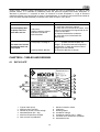
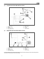
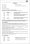
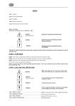
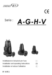
CHAPTER 1 - INTRODUCTION ....................................................................................................... 9
1.1
1.2
1.3
GENERAL SAFETY INSTRUCTIONS ................................................................................................9
GENERAL INFORMATION .................................................................................................................9
PRELIMINARY CHECKS ....................................................................................................................9
CHAPTER 2 - TECHNICAL FEATURES.......................................................................................... 9
2.1
LIMITATIONS ......................................................................................................................................9
CHAPTER 3 - INSTALLATION ...................................................................................................... 10
3.1
3.2
3.2.1
3.2.2
3.2
HYDRAULIC CONNECTION.............................................................................................................10
PRIMING............................................................................................................................................10
NEGATIVE SUCTION HEAD ............................................................................................................10
POSITIVE SUCTION HEAD ..............................................................................................................11
ELECTRICAL CONNECTIONS .........................................................................................................11
CHAPTER 4 – STARTING THE UNIT ............................................................................................ 11
CHAPTER 5 – MAINTENANCE AND TROUBLESHOOTING ....................................................... 11
CHAPTER 6 - TABLES AND DESIGNS ........................................................................................ 12
6.1
6.2
6.3
6.4
DATA PLATE .....................................................................................................................................12
POSITIVE SUCTION HEAD INSTALLATION ...................................................................................14
NEGATIVE SUCTION HEAD INSTALLATION..................................................................................14
ELECTRICAL CONNECTION BOARD .............................................................................................15
CHAPTER 7 – GUARANTEE ......................................................................................................... 15
8
CHAPTER 1 - INTRODUCTION
1.1
GENERAL SAFETY INSTRUCTIONS
Warnings for the safety of individuals and objects.
Carefully follow the instructions marked with the following symbols.
DANGER
DANGER
Warns that the failure to follow the directions given could cause
serious risk to individuals or objects.
Warns that the failure to follow the directions given may cause
electric shock.
Electric shock risk
WARNING
Warns that the failure to follow the directions given could damage
the electropumps.
WARNING: Read this manual carefully before installing this pump. Any damage caused by failure to observe
the directions contained in this manual will not be covered by warranty.
1.2
GENERAL INFORMATION
Series SSCX comprises single-bloc centrifugal electropumps, without self-priming device, with front suction,
radial delivery and with 1 stage. Every electropump is carefully tested and packed during its assembly.
1.3
PRELIMINARY CHECKS
WARNING
•
•
•
•
•
Always keep the original packaging for possible future transport of
the machine.
Check the packaging is intact
Open the packaging and remove the machine
Check the machine corresponds to that ordered
Check the machine is not damaged
If you receive an incorrect or damaged machine, notify PENTAIR PUMPS or the authorised dealer
within and not after 10 (ten) days from date of purchase
CHAPTER 2 - TECHNICAL FEATURES
DANGER
2.1
Do not use the product in environments with acid, corrosive and/or
inflammable gas
Do not use the motor pump with dangerous liquids.
LIMITATIONS
•
•
•
•
•
•
•
Ambient temperature
Maximum temperature of liquid
Level of protection
Maximum operating pressure
Power voltage
Inbound frequency
Maximum suction height
: +0°C to + 40°C
: 90 °C
: IP55
: 8 bar
: 1x230 Vac ± 10 % - 3x230/400 Vac ± 10 %
: 50 Hz + 3%
: 5 mt with standing valve (recommended)
9
CHAPTER 3 - INSTALLATION
3.1
DANGER
The installation operations must be performed by expert, qualified
personnel
Use specific guards and equipment as per safety standards
Fully comply with safety and accident prevention standards in force.
DANGER
Electric shock risk
Warns that the failure to follow the directions given may cause
electric shock.
HYDRAULIC CONNECTION
The system can be used with a direct connection to the aqueduct or suction from a first tank.
DANGER
For connection to the aqueduct, pay full attention to local standards
in force.
Check the sum of the intake pressure and the maximum pressure
of the motor pump do not exceed the maximum values allowed by
the system.
SSCX series electropumps are not self-priming. It is advisable to install it under the level of the water.
If the electropump is to be installed above the water level then a suction pipe should be used with a diameter
equal to that of the suction duct for electropump. If the height between the pump axis and the minimum basin
level is over 4 meters use a tube with a larger diameter. The suction line should be perfectly airtight. No elbows
and/or slopes should be present to prevent the formation of air locks that could affect the electropump
efficiency. A standing valve with filter should be fitted at about half a metre below the fluid that has to be
pumped on one end of the line.
Load losses can be reduced using delivery piping with a diameter equivalent or greater than the electropump
mouth. It is advisable to install a check valve directly on the delivery line to prevent the electropump being
damaged by "water hammer".
A cut-off valve should also be installed downstream from the check valve, to facilitate servicing operations.
Piping should be fitted so that vibrations, when existing, tension and weight do not affect the pump. Piping
should be routed along the shortest and straighter track, avoiding an excessive number of bends.
3.2
PRIMING
DANGER
Never start the machine if it is not completely filled with water.
3.2.1 NEGATIVE SUCTION HEAD
For negative suction head filling of a machine, proceed as follows:
• Close the gate on the delivery tubing
• Open the priming plug
• Slowly open the gate on the suction tubing
• When the liquid flows out of the priming plug continuously, tighten the plug.
• Fully open the gate on the delivery and suction tubing
10
3.2.2 POSITIVE SUCTION HEAD
For positive suction head filling of a machine, proceed as follows:
• Open the gate on the suction tubing
• Close the gate on the delivery tubing
• Open and remove the priming plug
• Pour the liquid into the machine through the priming plug hole until the liquid starts
overflowing
• Close the priming plug
• Start the machine
• Open the gate on the delivery tubing.
3.2
ELECTRICAL CONNECTIONS
WARNING
Verify that the voltage and frequency of the electropump shown on
the nameplate correspond to those available on the mains.
DANGER
Electric shock risk
The installer must make sure that the electric system is grounded in
accordance with the law in force.
DANGER
Electric shock risk
Make sure that the electric system has a high-sensitivity circuit
breaker D =30 mA (DIN VDE 0100T739).
Single-phase motors have a permanently inserted condenser and a thermal protection fitted on the motor
winding. Customers will be responsible for protections of three-phase motors. Electric connections should be
performed using cables H07RN-F (for external connections) or H05RN-F or H07RN-F (for internal
connections).
CHAPTER 4 – STARTING THE UNIT
WARNING
Use the electropump for the applications listed on the nameplate.
WARNING
Do not operate the electropump without fluids.
WARNING
Do not operate the electropump when the interception valve on the
delivery side is completely closet.
Before starting the electropump fill the electropump body as indicated at item 3.2 “Priming”, check that it
rotates clockwise when looking at the electropump from the side of the motor fan. On the three phase
electropumps it is possible to invert the rotation by changing the order of two phases. It is advisable to empty
the electropump and repeat the above-described operations, if the electropump is not used for long intervals
of time.
CHAPTER 5 – MAINTENANCE AND TROUBLESHOOTING
WARNING
DANGER
Electric shock risk
Make sure the machine is disconnected from electric power supply,
before performing servicing operation
11
Under normal conditions SSCX electropumps do not need any type of maintenance. In order to avoid
possible failures, it is advisable to periodically check the pressure supplied and current absorption. A
decrease in pressure is a symptom of wear. An increase in current absorption is a sign of abnormal
mechanical friction in the pump and/ or motor. If the electropump is not going to be used for long periods of
time it should be emptied completely, rinsed with clean water and put in a dry place.
PROBLEM
POSSIBLE CAUSE
The electropump does
not pump water, the
motor does not run
REMEDY
1) Verify the presence of voltage
2) Verify the cause and reset the switch. If the
thermal circuit breaker has tripped wait for the
system to cool down
3) Replace the defective condenser
4) Verify the cause and unblock the
electropump
1) No power
2) Motor protection tripped
3) Defective condenser
4) Shaft blocked
1) The pump is sucking air
1)
a) Make sure that the joints are
airtight. - b) Check that the level of liquid has
not lowered - c) Check that the foot valve is
airtight and is not blocked
2) Reset the direction of rotation
The motor runs but the
electropump does not
pump liquid
2) Wrong rotation direction
CHAPTER 6 - TABLES AND DESIGNS
6.1 DATA PLATE
PENTAIR WATER ITALY Srl
7
1
8
2
9
3
10
4
5
11
6
12
13
1
2
3
4
5
Type of motor pump
Maximum flow rate l/min
Number of phases / Power voltage
Absorbed power (Kw – Hp)
Maximum temperature of liquid
6
Date and year of production
7
8
9
10
11
12
13
12
Maximum head in metres
Frequency
Rotating speed
Condenser voltage
Condenser capacity (ver. 1~230V)
Insulation class and level of protection
Absorbed current
13
6.2
POSITIVE SUCTION HEAD INSTALLATION
3
7
4
6
1
5
4
2
1
2
3
4
6.3
Basin or tank
Filter
Shut-off valve
Non return valve
5
6
Motor pump
Gauge
7
Outlet tubing
NEGATIVE SUCTION HEAD INSTALLATION
1
7
4
3
6
2
1
2
3
4
3
4
Basin or tank
Filter
Shut-off valve
Non return valve
5
5
6
Motor pump
Gauge
7
Outlet tubing
For the installation of the positive suction head, ensure the correct inclination of the suction piping until the
air present in the tubing can exit the outlet tubing.
14
6.4
ELECTRICAL CONNECTION BOARD
CHAPTER 8 – GUARANTEE
This device is covered by legal guarantee based on the current standards in force for the country of purchase, relating to
manufacturing malfunctions and defects and/or those of the material used. The guarantee is limited to repairs or replacements,
in the assistance centres authorised by Pentair PENTAIR WATER ITALY Srl, for the pump or parts deemed malfunctioning or
faulty. The components subject to wear, for example, the mechanical seal and counter face, rings and seals, rotors and
hydraulic parts and membrane and electric cables are guaranteed for a period not exceeding their useful life. For the correct use
and duration of the product, as well as to avail of your right to guarantee, it is necessary to have parts serviced based on their
use by authorised assistance centres, as well as their possible replacement. To exercise your right to guarantee, in the case of
malfunctioning, directly contact the authorised dealer and/or the assistance centre. Possible notification of the faulty product
must be sent immediately after finding the anomaly and within and not after the terms specified by law. The right to guarantee
runs from the date of purchase and must be proven by the purchaser by presenting the proof of purchase document: receipt,
invoice or delivery document. The guarantee is forfeited: if the fault is caused by incorrect treatment or operations or incorrect
implementation or storage, incorrect electrical or hydraulic connections or no or inadequate protection or if the system or
installation of the device was not carried out correctly - if the fault is due to acts of God or other external or uncontrollable factors
- if the product is used with abrasive or corrosive liquids or different from those authorised or are incompatible with the materials
used in the construction of the pumps - in relation to product use, those beyond the plaque limits or conditions not allowed and
intervention by the purchaser or unauthorised personnel to fully or partially dismantle the product, as well as changes made or
tampering - if the materials are damaged due to normal wear - and any use different from those indicated in the use and
maintenance manual is not guaranteed if not expressly indicated in writing by the manufacturer. We recommend you carefully
read the instructions booklet in advance. Warning: If your device doesn’t work, check the fault is not caused for other reasons,
for example a power supply cut to the control or command device or mishandling.
Remember to attach the following documentation to the faulty device: receipt of purchase (invoice, receipt) and a detailed
description of the fault.
15