1
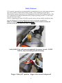
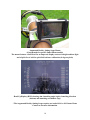
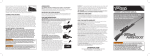
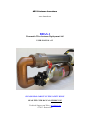
AE1S Antenna Launchers
www.kotarak.net
BDAS-1
Pneumatic Wire Antenna Deployment Aid
USER MANUAL v1.3
PLEASE READ CAREFULY THE SAFETY RULES
READ THE USER MANUAL BEFORE USE
Technical Support and Sales: [email protected]
© 2012 Kotarak.Net
SAFETY RULES Page 1 of 3
*** SAFETY FIRST! ***
The BDAS-1 Wire Antenna Deployment Aid is NOT A TOY!
Keep it away from children. It should NEVER be operated by individuals under the age of 18
years old without strict adult supervision.
DANGER!!! Improper charging, improper operation or misuse could
result in SEVERE INJURIES or DEATH! Follow the Safety Rules!
This is a high-energy store-and-release projectile launching system, using compressed air or CO2
at pressures up to 100 PSI. The projectile leaves the system at extremely high and potentially
lethal velocities.
NEVER point or activate the launcher at another person, animal or personal property!
NEVER deploy launcher near or over high-voltage power lines!!! The leader line (although
made of a generally non-conductive material) could have enough high-voltage conductivity due
to moisture and / or contaminants to cause electrocution or flash arc explosion.
NEVER drop the launcher or subject it to excessive vibrations or strong mechanical shock
NEVER operate a launcher showing any sign of damage – broken / cracked / missing parts
NEVER attempt to repair or maintain a launcher with pressurized tank.
NEVER insert any foreign objects in the barrel or attempt to launch projectiles other than the
approved and supplied with the launcher tennis balls.
NEVER charge or operate the launcher in temperature below 10 degrees C (50F) or above 40
degrees C (100F)!
NEVER leave the launcher inside a motor vehicle for lengthy periods of time – especially during
seasons with extreme temperatures
NEVER transport charged launcher in a vehicle!
NEVER store launcher with pressurized tank!
NEVER leave the launcher unattended while charging!
1
SAFETY RULES Page 2 of 3
NEVER rely on the Safety Relief Valve to act as “charge limiter”. The valve is installed as a
preventive measure. Compressor or CO2 regulator should be turned off immediately when the
pressure gauge indicates pressure near the maximum recommended pressure.
NEVER exceed the absolute maximum limit of 100 PSI. Recommended maximum operational
pressure is 80 PSI.
NEVER tamper with the safety features or attempt to modify the launcher.
NEVER store the ramrod inside the barrel
NEVER use the launcher outside of its design purpose
***
ALWAYS stay alert and use common sense while using the system
ALWAYS treat compressed gas and high-velocity projectile systems such as this one with
respect
ALWAYS point the barrel AWAY from any people, animals or personal property while
charging or activating the system.
ALWAYS use personal protective gear when using the system – safety glasses, hard hat, ear
protection and leather gloves
ALWAYS use the Safety Relief Valve when bringing the launcher from and to storage.
ALWAYS handle with care – a damaged launcher or charged system, subjected to extreme
shock (drop) or operated outside of its specifications could undergo explosive decompression
failure, sending off high-velocity fragments.
ALWAYS perform thorough visual inspection of the launcher BEFORE charging, looking for
any sign of damage.
ALWAYS perform visual inspection inside the barrel, looking for any foreign objects only
AFTER operating the Safety Relief Valve and BEFORE charging
ALWAYS try to charge the system at the site of deployment or nearby in order to minimize
transportation in a charged state.
ALWAYS observe the pressure gauge while charging the system and be ready to disconnect the
pressure source.
2
SAFETY RULES Page 3 of 3
ALWAYS install the trigger safety strap BEFORE charging and remove it IMMEDIATELY
BEFORE launching.
ALWAYS make sure the ramrod is removed from the barrel immediately after loading.
ALWAYS store the launcher according to the storage temperature specifications, in a dust-free
environment and away from any corrosive chemicals or organic solvents.
ALWAYS evaluate the antenna deployment site for the risks associated with high-velocity
projectile and falling objects
ALWAYS make sure that everybody is clear from the deployment area before launching.
Immediate hazards associated with the use of the launching system include but not limited
to high-velocity projectile, high-velocity line, high-velocity plastic or metal fragments as
well as secondary hazards, resulting from the application of the system (i.e. falling debris
from trees).
The BDAS-1 Wire Antenna Deployment Aid is built to the highest standards, using high-quality
materials and assembly procedures, and it is guaranteed to be free of defects.
The system incorporates many safety features, has been thoroughly inspected at the factory and
tested at pressure of 90 PSI. (Safety Relief vents above 90 PSI) This pressure rating is
conservative and gives the necessary safety margins. The maximum recommended operating
pressure is 80 PSI. The system incorporates a Safety Relief Valve which will automatically
reduce the pressure by venting it, if accidental or purposeful attempt is made to exceed the
factory-set absolute maximum limit of 100 PSI (It is completely normal for the Safety Relief
Valve to begin vent at ~ 90 PSI). Do NOT tamper with this valve – it is installed for your safety!
LIABILITY
The manufacturer can not be held responsible and is not liable for ANY
injuries, death or personal property damage resulting from the use of this
system. The Buyer assumes any and all liability. By purchasing this item you
are agreeing to hold us harmless of any damages or injuries incurred. It is the
Buyer’s responsibility to use this product in a safe manner, exercising
common sense and following the safety rules for working with high-energy
store-and-release systems! THIS IS NOT A TOY and should not be used by
children. By purchasing this item you are declaring to be 18 years of age or
older and that you have checked your state and local laws for prohibition and
restrictions on such devices!
3
Thank you for purchasing BDAS-1 Wire Antenna Deployment Aid.
This a new generation no-compromise tool with improved safety features, performance,
reliability and visual appearance! It is the ultimate solution for deploying wire antennas, offering
top-of-the-line performance and extreme accuracy, while saving valuable time. Now you can
install the antenna faster, with less effort and have more time to operate.
We hope that you will enjoy using it as much as we enjoyed building it for you.
Purpose
The BDAS-1 Wire Antenna Deployment Aid is designed to help an amateur radio operator with
deployment of wire antennas in the field or for permanent installation.
Long Wire, Dipole, Sloper, Inverted-V, Loop and many other types of wire antennas require one
or more support structures in order to raise the whole antenna system or part of it, high above
ground. In field deployment for portable operation or special events such as Field Day, the
station is often located in wooded area and tall trees are used for antenna support.
Hoisting a dipole antenna between two tall trees will require an antenna support rope to go over
the crown of each tree – sometimes at heights of over 100 ft. Contraptions like a sling shot with
a fishing reel mounted, a bow and an arrow or a casting rod are used to toss a small weight
attached to a fishing line, but these methods limit the maximum height and offer low accuracy,
requiring many attempts.
BDAS-1 is a pneumatic canon type launcher specifically designed to aid the task of getting the
support rope high over the trees. It uses compressed air or CO2 to launch a projectile (weighted
tennis ball) on a desired trajectory over tall objects. The projectile is towing a thin, strong leader
line while traveling on its trajectory. This type of launcher offers unmatched performance,
accuracy, power and repeatability of the launches at a modest price.
Theory of operation
The BDAS-1 kit is comprised of three main components – a Pneumatic Launcher, a muzzlemounted Zip Reel loaded with leader line and a projectile.
The Pneumatic Launcher is a system of compressed gas storage tank, a pneumatically actuated
rapid-release main valve, a trigger valve, a U-interconnect and a barrel. It is a “folded” design,
placing the tank under the barrel making the whole system more compact and easy to use.
During charging, CO2 (from bottle) or air (from an automotive manual / foot operated pump or
an electric compressor) is pumped and stored in the storage tank until desired gas pressure is
reached.
The main valve is normally closed by a membrane, pushed against its saddle by a spring. Behind
the membrane there is a separate chamber connected to the high-pressure side via a small
opening. This connection maintains equalizing high-pressure, which also exerts additional force
on the membrane, pressing it to the saddle and completely sealing it off. The saddle is located at
the valve’s low-pressure outlet and the pressure difference keeps the valve tightly closed. Launch
is initiated by depressing the trigger valve. The trigger valve vents the equalizing pressure behind
the membrane. High-pressure gas from the valve’s inlet pushes the membrane away from the
saddle due to the sudden drop of pressure behind it. This force is much greater than the force of
4
the spring trying to keep the valve closed. When the membrane is pushed away from the saddle,
it opens a path between the valve’s inlet and outlet. As the valve opens, compressed gas flows
into the barrel where it expands rapidly in the cavity behind the projectile. The projectile is
propelled forward in the barrel by the expanding gas and accelerates with the rate of the gas
expansion. Upon leaving the barrel, the force of the projectile unwinds a thin leader line from the
muzzle-mounted Zip Reel and tows the line along on its trajectory.
The key components, determining the performance of the launcher are the tank-to-barrel volume
ratio, barrel length, the pressure of the gas in the pressure vessel and the rapid action of the main
valve. Other factors such as friction force inside the barrel, drag and wind also contribute to the
parameters of the resulting trajectory.
Performance
BDAS-1 will launch a weighted tennis ball (4 oz), towing 50lb Test Spectra Line loaded on Zip
Reel to altitudes of well over 200 ft near its maximum pressure limit. Muzzle velocity could
exceed 120 MPH. Results may vary from launch to launch or site to site as there are many
factors contributing to the exact performance values at any given moment – air temperature,
altitude, atmospheric pressure, humidity, angle of launch etc.
Performance with 4 oz Tennis Ball towing 50 lb Test Spectra line:
@50 PSI trajectory peak occurs at over 150 feet.
@35 PSI trajectory peak occurs at over 100 feet.
User Notes
Pressure
Angle
Launch Data:
(Trajectory Peak, Distance, Conditions)
5
Technical Specifications
Overall Length:
Weight:
Barrel:
Pressure Tank
Chamber:
Pressure Tank Volume:
Barrel-to-tank ratio:
Main Valve:
Material Pressure
Ratings:
Absolute Max Pressure:
CAUTION:
Operational Pressure:
Safety Relief Valve:
Operating Temperature:
Storage Temperature
Zip Reel:
Standard Load:
CO2 Cartridge Usage:
approximately 23 inches (58 cm) with no Zip Reel installed
approximately 8 pounds (3.5 kg) with no Zip Reel installed
18 inches length (45cm), 2.5 inches diameter (6.3 cm)
10 inches length (25.4 cm), 4" diameter (10.16 cm)
>125 cu in (>2 liters)
> 1.42:1
1" sprinkler valve, modified for fast-acting pneumatic actuation
Main Valve is rated to 150 PSI by the Manufacturer.
PVC components used in the pressure tank and other assemblies
are rated for at least 220 PSI max working pressure by the
Manufacturer.
100 PSI (pressure levels above 100 PSI are considered extremely
unsafe for this system and have not been tested)
Exceeding 100 PSI may damage the Pressure Gauge.
80 PSI (551 kPa) (max recommended); 90 PSI (max possible)
Fully open @ 100 PSI
(valve will begin venting if pressure exceeds ~90 PSI)
10C (50F) to 40C (100F)
0C (32F) to 48C (120F)
~ 2 ft perimeter
150 yards, 50lb Test, High-Visibility Yellow Spectra Line
Tank @ 50 PSI requires approximately 0.5 oz. per launch
(total of about 24 launches per 12 oz. cartridge)
6
BDAS-1 Complete Kit
Friction Mounted Zip Reel (included)
Loaded with 150 yards of 50 lb Test Hi-Vis Yellow Spectra Line (braided)
7
Safety Features
PVC material is generally not recommended by its manufacturer for use with compressed gasses
due to the potential of fragmentation during a failure, while containing pressurized gas.
This Launcher operates at pressure levels, substantially below the rated working pressure of the
PVC components, providing an additional safety margin (operating pressure is ~3 times lower
then mfr’s pressure rating).
All PVC components are rated at 220 PSI or greater and are solvent welded, using heavy duty
glue and additional PVC primer applications to achieve maximum strength bond.
BDAS-1 is utilizing only proper fittings and reducers in the Launcher assembly (all
pressure rated) and was built with Safety as a priority!
Safety Relief Valve will open automatically if pressure exceeds ~ 90 PSI
Pull the ring for manual pressure discharge.
Trigger “Safety ON” position – trigger valve can not be depressed
8
Trigger “Safety OFF” – Trigger is released and ready
Augmented Reality Aiming Scope (*Optional)
The Augmented Reality Aiming Scope Mount is designed for Smart Phone owners and
offers unmatched accuracy and set of features.
The unique concept for using a Smart Phone as an aiming scope was developed by AE1S
Antenna Launchers. BDAS-1 is the FIRST and ONLY Pneumatic Launcher to offer it!
9
Augmented Reality Aiming Scope Mount
(Custom made for specific Smart Phone models)
The mount features a Soft Hood for an improved display contrast in bright ambient light
and a Spirit Level Aid for quick field software calibration (0 degrees pitch)
Head-Up Display (HUD) showing aim, launching angle (right), launching direction
(bottom) and launching coordinates (top)
* The Augmented Reality Aiming Scope requires an Android OS or iOS Smart Phone
Contact us for more information.
10
Operating instructions
Preparing, Charging and Loading the Launcher
Step 1: Pull the ring of the pressure relief valve and hold it open for a couple of seconds.
Observe the pressure gauge. The needle should be showing zero pressure and no gas should be
escaping through the valve.
Step 2: Hang the trigger safety strap on the strut support screw lug in “safety position”
Step 3: Perform visual inspection. Look for any broken/cracked/missing parts. Check carefully
for fractures around the pressure vessel/valve area. If there are chips or scratches in the paint,
inspect the area carefully. Chipped or scratched paint could be evidence of “mistreatment” or
result from accidental mechanical shock.
Step 4: Look into the barrel. Check for any foreign objects.
Step 5: Attach the Zip Reel by slipping and pressing the coupler onto the muzzle. Release
approximately 2 feet of line. To prevent the line from further unwinding, use the Zip Reel’s Line
Holder fingers. Tie the tennis ball tail loop to the line. Make sure that the ball is securely tied.
TIP: The standard projectile is a weighted tennis ball – weight is increased to 4 oz as the extra
mass offers superior pulling force for the line, especially as the ball comes down and there is
increased friction between the leader line and tree leaves and branches. In certain cases a
lighter or heavier ball might be required. The kit includes 4 oz tennis balls (2 of each) and one
(marked “6”) extra-heavy 6 oz tennis ball. Standard tennis ball with no additional weight is 2 oz.
.
Step 6: Using the ramrod, push the tennis ball down the barrel until it bottoms out.
Step 7: REMOVE the RAMROD from the barrel! Make sure that there is no excessive slack of
line. Too much slack can snag on the barrel or the Zip Reel mount. Use the Line Holder Fingers.
Step 8: Place the launcher on a flat surface, aiming it in a safe direction. Remove the cap of the
Fill Valve and connect compressor, CO2 bottle with regulator valve or manual / foot pump.
Step 9: Start pumping air while observing the pressure gauge. Do not let the pressure exceed 80
PSI. Do not rely on the Safety Relief Valve to serve as a “charge limiter”.
TIP: A couple of “dry” test launches (just tennis ball, no leader line) at different pressure levels
are recommended to determine the optimum launching pressure and angle for the desired
trajectory. Start with 30 PSI and adjust accordingly until you achieve the desired trajectory.
Step 10: Disconnect the hose from the Fill Valve as soon as the desired pressure is reached.
If you “overshoot” the goal pressure, use the needle of the Fill Valve to drop it to the desired
level. Replace the Fill Valve cap.
11
Launching
Step 1: Carefully select optimal launching position and distance to the object. This will depend
on the height of the tree / structure, shape of the crown, terrain, etc. and it will determine the best
launching angle and pressure to achieve the desired trajectory.
* Launching from too close will require a steep launching angle. The horizontal travel distance
will be relatively short and there is a potential risk for the projectile to hit the crown when
launched or to fall into the canopy of the tree on the way down. Compensating with higher
launching pressure might result in an over-shoot and higher risk for the leader line to be blown
away by the breeze.
* Launching from too far will increase the projectile’s travel time and this might affect the
accuracy due to existing breeze conditions. It will also require higher launching pressure and
more leader line. There is a risk for the projectile, falling short into the canopy or an over-shoot.
Step 2: Support the launcher with your left hand by holding it underneath the front part of the
pressure tank. Use your right hand to hold the trigger valve grip.
TIP: Avoid using the launcher in strong winds. If the breeze is gusty, wait for a calm moment.
Correct the launching direction under constant breeze. A couple of “dry” test launches with no
line are recommended to establish the desired trajectory parameters – angle and pressure.
When launching with a leader line, “pad” the launching angle, aiming slightly higher – the tow
line adds additional drag force and will affect slightly the trajectory.
Do not overshoot by aiming too high and / or using too much launching pressure – try to keep
the trajectory somewhat snug around the object (tree). If the trajectory is too “loose”, the breeze
can blow the line away from the desired location when the projectile reaches the trajectory peak
and has zero pulling force (just a moment before it starts falling down).
In a densely wooded area, “overshoot” could cause the line to go over more than one tree and /
or tangle into branches. Avoid shooting between branches – generally, going over the canopy of
the tree yields better results and the risk of hitting a branch and getting a tangled line is lower.
Step 3: Remove the orange safety strap from the trigger support bracket lug (“Safety OFF”
position). Aim the launcher, looking right above the end of the barrel. Place your thumb on the
trigger when ready to launch.
Step 4: Holding the launcher steady, depress the trigger QUICKLY and SMOOTHLY,
HOLDING IT DOWN for a moment. The projectile will leave the barrel at high velocity,
accompanied by a loud noise of rapid decompression.
IMPORTANT: Immediately after the launch, do not move the launcher from your aim. Hold
the launcher in the same position and maintain the same launching angle UNTIL the projectile
falls on the ground and no more line is dispensed from the Zip Reel. If you move the launcher
prematurely and abruptly right after launch (for instance, lowering the muzzle down), the line
could snag and break under the pulling force. The Zip Reel axis must remain lined up with the
launching direction in order to dispense the leader line properly.
12
Step 5: Lay the launcher carefully down, onto the ground (do not throw it!!!) and remove the Zip
Reel mount from the barrel by gently twisting and pulling it.
Pulling an antenna rope
Step 1: Remove the tennis ball from the far end of the line and securely tie the line to a lightweight rope with the necessary length – avoid splicing different lengths of rope for the initial
pull.
TIP: The braided Spectra line is 50lb TEST type and it is strong enough to support and pull
almost any length of the smaller diameter Dacron type antenna rope, assuming there is no snag
on tree branches. If you are planning to raise a heavy antenna system, consider using a lightweight rope for the initial pull and then use that rope to pull the heavier work rope.
TIP: Use electrical tape to cover the joint between the leader line and the antenna rope,
tapering off the junction point. This will reduce the chance for snag on branches when the rope
is pulled by the leader line through the tree crown. The Zip Reel of BDAS-1 comes pre-loaded
with 150 yards of braided 50lb TEST High-Visibility Yellow Spectra line. It can be replaced with
stronger leader line if necessary.
Step 2: Start pulling the line slowly (use work gloves to avoid cuts), while somebody else feeds
the antenna rope on the other side, assuring there is enough slack and resistance is minimal.
TIP: If the line snags when going over a branch – try to work it back and forth with light tugs –
do not force it too much or the line might break.
Make an effort to lay the line on the ground in a way so it does not get tangled or knotted (if
there is another helper available, one person can pull the rope, while the other is winding the line
back on the Zip Reel)
Step 3: When you get the end of the antenna rope, disconnect the leader line.
HINT: The Zip Reel is equipped with a handy line cutter (located under the front bracket)
Step 4: Wind the leader line back on the Zip Reel for the next launch.
The winding should cover the Zip Reel evenly and should be VERY lightly tensioned (do not
tension too much or it will not dispense properly). Do not rotate the Zip Reel while winding.
Insert the end of the line between the Line Holder Fingers and make a couple of loops.
Step 5: Squeeze the trigger valve one more time while pointing the barrel to the ground to
release any residual pressure in the chamber. Alternatively, you can pull the ring of the safety
relief valve.
13
Other applications
The general purpose of the launcher is to get a leader line (used to pull a work rope) over a very
tall object. It could be used to aid the hanging of Flags, Christmas lights, Banners, Swings, etc.
(Avoid using it near buildings or vehicles - the projectile can break windows or dent vehicles).
The launcher will also cover substantial horizontal distance when aimed low (35-45 degrees) and
it can be uses as improvised “line thrower” in marine applications, rescue / emergency
applications, throwing a line between buildings, across small bodies of water etc. (This launcher
is not a professional rescue / emergency equipment nor is intended to replace such)
BDAS-1 with its 2 ½ inch diameter barrel can also be used to launch streamers, confetti and Tshirts for special events and parties (use only outdoors with extreme caution, observing the safety
rules!). Place a wad of paper or soft cloth before loading the barrel with confetti or streamers to
prevent clogging of the main valve. Remove any wrappers and packaging when using it with
streamers and confetti.
Storage
The BDAS-1 Wire Antenna Deployment Aid kit should be stored at temperatures between 0C
(32F) and 48C (120F), in a dust-free environment.
Store the Launcher away from corrosive chemicals or organic solvents. Do not leave it under
direct sun light for lengthy periods of time!
The launcher has a painted finish - take measures to preserve the surface and avoid chips and
scratches to the paint.
Treat the launcher as a fragile item!
The pressure gauge is installed in a location which will minimize the chance for damage but one
should be aware that this is a precision instrument in a plastic housing and could be damaged by
excessive weight during storage.
Avoid storing the launcher with the trigger valve side facing down to reduce the chance for
external mechanical force to the main valve and trigger components.
The best way to store the BDAS-1 System is in a large padded bag, a card-board box with foam
inserts or a plastic tote.
14
Maintenance
BDAS-1 Launcher is designed for a very long exploitation life and has excellent reliability. It
should offer thousands of launches if treated properly.
Perform a visual inspection BEFORE every use.
Perform an annual maximum pressure test: Wear safety gear! Make sure the barrel is empty.
Wrap the launcher tightly in a heavy moving blanket. Charge to 85 PSI and wait for 30 min.
Note the starting and final pressure to detect serious leaks. While the launcher is still wrapped,
try to raise the pressure to 100 PSI in order to test the Safety Relief Valve. Be ready to
immediately disconnect the pressure source if the pressure exceeds 95 PSI. The Safety Relief
Valve should open before this level (likely around 90 PSI). The pressure will suddenly drop to
approximately 30-40 PSI (accompanied by a venting noise). Disconnect the pressure source and
release the tank pressure by pulling the Safety Relief Valve ring.
The launcher is made almost entirely out of PVC plastic. Do not use it if you notice a deep
scratch on the Pressure Tank or ANY CRACKS as this could compromise the pressure
ratings. A damaged launcher should be immediately repaired or destroyed.
There are no user-serviceable parts inside. NEVER attempt to disassemble any part of this
product. Contact the manufacturer with Service Request.
Cleaning should be done with a moist towel. Use soapy water if necessary and lightly wipe the
surface! Avoid vigorous scrubbing to protect the finish.
NEVER use solvents to clean the launcher.
Use compressed air or a soft brush to remove debris from the Safety Relief Valve openings and
the Fill Valve. Always keep the cap of the Fill Valve on, when not in use.
A word about the surface finish
The launcher has a painted surface. Painting was done to improve the aesthetics and enhance the
visual appearance. Unfortunately, the assembly can not be easily covered with the more durable
powder coating – “baking” stage of the powder coating could compromise the pressure rating.
Paint, specifically formulated for PVC plastics is used for the finish. The PVC surface is also
prepared in a way to enhance the adhesive properties of the paint.
PVC plastics give much softer base to the paint than metal and have lower adhesion - the surface
is prone to scratches, chips or flaking if treated “roughly” or exposed to abrasive particles.
As the Launching System is used outdoors, and Launcher is often placed on the ground (among
abrasive dirt and rocks) and transported with vehicles, it is the buyer’s responsibility to make
the best effort to preserve the painted finish if aesthetic appearance is considered an
important feature.
Due to the nature of the product and materials used, the manufacturer does not guarantee this
product against any cosmetic defects, scratches, chips, flaking paint or wear that might result
from normal use and handling.
15