1
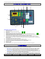
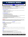
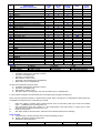
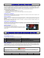
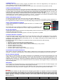
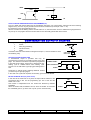
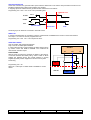
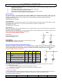
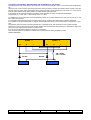
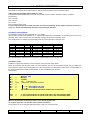
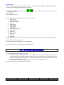
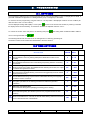
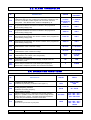
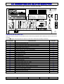
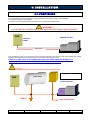
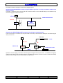
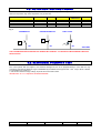
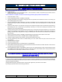
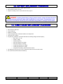
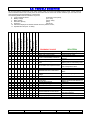
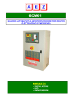
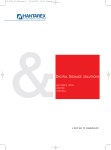
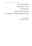
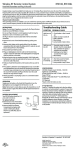
GCM01 AUTOMATIC MICROPROCESSOR CONTROL PANEL FOR STAND-BY GENERATOR MANUAL: • INSTALLATION • USE • MAINTENANCE INDEX DESCRIPTION 1. PAGE USER MANUAL 3 1.1. Purpose 1.2. Operational principle 1.3. View of the GCM01 unit 1.4. Controls 1.5. Maintenance 3 3 4 4 6 7 2. TECHNICAL MANUAL 2.1. Constructional description of the control panel 2.2. How it works 2.3. Manual control functions 2.4. Various functions and standard utilities 2.5. Configuration output 11 starter 2.6. External commands 2.7. Special functions 2.8. Optional expansions 7 8 10 10 12 14 16 17 18 3. PROGRAMMING 3.1. Settings 3.2. Time settings 3.3. Alarm thresholds 3.4. Operating functions 3.5. Measures regulation 3.6. Clock and hour recording meter 3.7. Self-programming 3.8. Connections and relative description 3.9. Technical features 18 18 19 19 20 20 21 22 23 25 4. INSTALLATION 4.1. Positioning 4.2. Power connections 4.3. Starting 4.4. Stopping 4.5. Motor controlling probes 4.6. Electrical strength test 25 26 26 27 28 28 29 5. SERVICE PROCEDURES 5.1. Servicing procedures 5.2. Servicing procedures with mains supplying (disabled generator) 5.3. Battery replacement procedure 5.4 GCM01 Board replacement procedure 29 29 30 30 31 6. MAINTENANCE 6.1. Electrical maintenance 6.2. Efficiency test 6.3. Motor safety devices 6.4. Generator safety devices 6.5. Overload protection 51 6.6. Battery efficiency 6.7. Switching scaling test 6.8. Trouble shooting FILE GCM01-MU-GB-12.2.doc REV 12.2 31 31 31 31 31 32 32 33 DATE 18/01/2007 LANGUAGE EN PAGE 2 of 33 1. USER MANUAL GENERAL FEATURES We congratulate you for having purchased the GCM01 control panel for handling your generator unit. As you read through this manual you will realise the outstanding performance and variety of applications offered by this supremely technological unit. This electronic microprocessor module not only completely controls the generator and its switching but, is also prearranged for the direct serial communication with a PC. Moreover using a GSM unit, your generator can be completely remote controlled from miles away. The GC-M02 unit is equipped with a complete set of digital testers that are required to monitor all mains, generator and motor parameters. To make the control of the unit absolutely comprehensible the manual is split up into two parts, namely: 1. The first USER MANUAL part has been prepared to provide a clear and simple guide to help you use the generator rapidly, completely and safely. 2. The second TECHNICAL MANUAL part has been prepared to provide complete and detailed instructions for skilled personnel to start up the generator correctly. 1.1 PURPOSE The manual has been prepared specifically for the user of the generator unit. Information required for the following is provided: 1. To learn the operational principle of the unit; 2. To interpret the indications given on the electronic control panel; 3. To control it for the various operational requirements; 4. To perform the basic checks required ensuring the efficiency of the generator itself. Technical or adjustment matters are not dealt with as these involve the installation engineer when setting up the system. 1.2 OPERATIONAL PRINCIPLE HOW DOES A STAND-BY GENERATOR UNIT WORKS Fig.1 shows the system components that consist of a public mains R, a generator unit G-M, and a command and control panel QGE with a built-in mains contact maker CR, a generator unit contact maker CG and the GCM01 module QGE GCM01 R CR C G M Fig. 1 USERS Supposing that the mains R is within the normal limits, the CR mains contact maker is closed therefore the utility is powered from the mains. The GCM01 module controls the R mains and if there should be a drop in voltage, a phase should be missing or the phases should be dissymmetrical, the control panel: 1. Opens the CR mains contact maker; 2. Starts the G-M generator unit, which when the established operating conditions are reached, the GCM01 module closes the CG contact maker that then powers the utility from the generator unit G; 3. When running, the engine M and the generator G are safeguarded against possible anomalies, which if encountered cause to stop the generator immediately; 4. When the R mains is restored within the normal limits, the GCM01 module after an adjustable delay, opens the contact maker of the CG generator and one second later closes the CR contact maker, thus powering the utility from the mains again; 5. The generator continues to run for at least another minute to cool down after which it stops automatically; 6. Only reserve and overload. To ensure the perfect efficiency of the generator a battery charger automatically holds the battery perfectly efficient. An automatic fuel filling system constantly keeps the correct level in the daily tank. A pre-heating system maintains the motor FILE GCM01-MU-GB-12.2.doc REV 12.2 DATE 18/01/2007 LANGUAGE EN PAGE 3 of 33 at the ideal temperature so that it is ready to start whenever necessary. 1.3 VIEW OF THE GCM01 UNIT 8 6 4 15 1 5 7 9 12 10 11 3 14 2 13 Description of the components 1 2 3 4 5 6 7 8 9 10 11 12 13 14 15 : Programming switch : Start button only with (1) manual start mode. : Stop button : Display reading selection push buttons display (6). : Reset/Enter push button used to reset the functions and to eliminate an alarm status and also to confirm parameters entered in the programming phase. : Alphanumerical display that shows all the parameters together with the literal description of the type of alarm : Leds which show the visualized measure, and indicate parameter’s anomaly if flashing. : Led for engine alarm, (a) battery charter dynamo failure, (b) oil pressure low, (c) engine temperature high, (d) water/oil level low, (e) fuel reserve, (f) remote and local safety stop button ON, (g) reserve alarm 1 (to define), (h) start failure alarm. : Led indicates mains presence within normal limits. : Led indicates mains contact maker closed and use supplied by mains. : Led indicates generator unit contact maker closed and use supplied by generator unit. : Intervention led of generator overload protection, has to be reset manually. : Generator unit ON : Supplied module. : Led PROG/WAIT; fixed: programming mode, flashing: timing phases or automatic running delay. 1.4 CONTROLS The operational modes that can be selected with the programming switch are six, namely: 1. 2. 3. Automatic test: This starts to test the generator without disconnecting the mains power supply from the utility. When the switch is turned back to automatic mode the generator stops following a delay of roughly one minute (it is used for periodic tests or to check the running efficiency following maintenance). Automatic mode: if there should be a failure in the mains the circuit board responds by opening the mains contact maker. Once the mains is re-connected, after a certain time, the utility is switched back to the mains and the generator is stopped (this is the normal operational situation). Lock: this sets the generator in a locked status. It completely disables every possibility of starting while the mains powers the utility. This mode is used to work on the system in complete safety, being certain that the FILE GCM01-MU-GB-12.2.doc REV 12.2 DATE 18/01/2007 LANGUAGE EN PAGE 4 of 33 4. 5. 6. generator will not start even if the mains should be disconnected (it is used during maintenance).The mains’ voltage control it’s not active. Manual mains: this enables power supply output from the mains even if the command and control electronics are faulty (it is used when the generator is left inoperative). Manual starting: this enables the generator to be started manually using the start push button. The control is direct without the involvement of electronic components. It ensures the operation of the generator even when the electronics are faulty (it is used for the manual emergency controls or for maintenance purposes). Manual generator: this enables the forced power supply from the generator (it is available for manual procedures or in the case of problems with the automatic functions). WARNING When the programming switch is in this position all the utility circuits of the generator are powered such as the solenoid valves, electronic rpm regulators etc. If the switch were in this position with the generator stopped the starting battery would run flat very quickly. STOP This is enabled whatever the situation (enabling even only in manual mode) It is to be held down until the motor stops completely EMERGENCY STOP If pressed, the red mushroom push button in the middle of the door stops the generator immediately, instantaneously opening the contact maker of the generator (CG) thus locking it. To release the emergency status set the programming switch in Lock position and then turn the emergency push button and pull up. A newly conceived and remarkably useful LED has been fitted on the GCM01 module to assist the operator, namely the WAIT/PROG LED. This LED flashes each time the timer is triggered informing the operator what is happening even over a lengthy timer period. All leds are provided with a general description that makes the control panel easily comprehensible. LED TEST To verify the functioning of all the leds, bring the programming hand grip to lock.Hold the + /- push buttons down together for 2 seconds. ALARM SILENCING Hold the RESET key down for 2 seconds to silence the buzzer alarm. FUNCTIONS RESET Hold the RESET key down for 2 seconds to reset the alarm status and to restore the functions. SUMMERY In normal running the generator unit is programmed in AUTOMATIC mode. During maintenance on the generator unit put it on LOCKED ENGINE. With no intervention need even in case of mains failure, set the programming switch in MANUAL MAINS. Thus the supply by mains would be assured. CLC SIGNAL With the setting of the automatic TEST or AUTOMATIC LOCK, in case of disconnection of the battery the timer has to be reprogrammed. To indicate the loss of the programming, on the display appears CLC for 0,5” every 1,5”. It does not have any influence on emergency functioning; it is only a call-up for the re-programming of the timer. FLASHING HOUR LED Indicates maintenance requirement when programmed hours are up. HOW TO PROCEED IF THE GENERATOR SHOULD FAIL TO WORK A possible alarm status will be shown on the display. Whatever the anomaly, the cause is to be found first and foremost then press the RESET push button twice. The causes and the solutions differ depending on the type of anomaly involved: 1. Flashing led 7: electrical anomalies due to min./max. voltage and frequency. If the anomaly should persist after the RESET push button has been pressed then request technical assistance; 2. Led .8: anomaly due to low oil pressure,(b) high motor temperature,(c) low water or oil level,(d) fuel reserve.(e) Check the relative levels (water, oil, fuel) and top-up if necessary then reset; 3. Led .8: anomaly of the battery dynamo. (a) In this case request technical assistance; 4. Led .8: alarm(f) due to local or remote emergency stop status. Set the programming switch on LOCKED mode, turn and pull the emergency push button enabled then reset; 5. Led .8: alarm due to failed starting,(h) try starting with manual control and inform the supplier; FILE GCM01-MU-GB-12.2.doc REV 12.2 DATE 18/01/2007 LANGUAGE EN PAGE 5 of 33 6. Led 13: The generator overload protection switch has tripped. It is to be reset manually by a qualified engineer (see maintenance section). 1.5 MAINTENANCE SECURITY PROCEDURES FOR THE USER WARNING It is strictly prohibited for anyone to touch powered parts. 1.5.1 ELECTRICAL MAINTENANCE Skilled personnel must perform all jobs. The control unit is equipped externally with all the possible command, control and reset functions. Proceed as follows to access the equipment within the control panel: 1. Set the programming switch on LOCKED mode. 2. Check if the unit has stopped completely. 3. Disconnect the mains line that powers the control panel and switch the main switch ON/OFF of the mains off. 4. Check if the mains has been effectively disconnected, which can be seen by the mains OK LED switched off and by the display switched to the mains that must indicate zero. 1. Open the control panel and check for any anomalies in the: • Fuses; • Automatic switches; • Thermal relays. Once maintenance has been completed repeat the procedure in reverse order to reset the unit. MECHANICAL MAINTENANCE 1.5.2 If the generator should fail to start due to an anomaly in the fuel circuit and also in an emergency status, the following tips may prove useful. How restore the fuel circuit: 1. Set the programming switch on Manual Start mode without starting the generator. In this way the 15/54 that powers the fuel interception solenoid valve is activated. 2. Once you have filled up with fuel, operate the hand pump situated on the motor until the circuit is restored, which can be seen by the pump becoming harder to move. 3. Start in manual mode (It is advisable to restrict the starting attempts to 10 seconds each with a pause of 15 seconds in-between to allow the battery to recover efficiently). Once the unit has started and is running regularly reset the automatic functions. 1.5.3 PERIODIC CHECKS To keep the unit efficient some periodic checks must be made together with those scheduled by the manufacturer of the motor and by the installation engineer: 1. 2. 3. 4. Check the electrolytic level of the battery every 15 days following installation and request the assistance of an engineer if an excessive consumption is noticed. Following the initial period check every 90 days; In generators complete with motor pre-heating system check if the motor is warm each time a check is made otherwise request technical assistance. (WARNING: a cold motor at low temperatures could have difficulty in starting or outputting once started); If the generator is rarely triggered due to the lack of mains power supply execute an automatic test for at least 2 minutes. If new electrical machines are installed in the system powered by the generator, request technical assistance to check the suitability of the CG/CG mains/generator switching to the new load. SUMMERY On a periodic basis check the electrolytic level of the clear batteries. Touch the motor to feel if it is warm (if equipped with pre-heating system) and execute an automatic test. FILE GCM01-MU-GB-12.2.doc REV 12.2 DATE 18/01/2007 LANGUAGE EN PAGE 6 of 33 2. TECHNICAL MANUAL 2.1 CONSTRUCTIONAL DESCRIPTION OF THE CONTROL PANEL The control panel is entirely manufactured in compliance with the following European standards: ANS low voltage electrical control panels EN 60439-1 EMC electromagnetic compatibility directive 89/336/EEC Each control panel or device is completely tested and supplied with test certificate, declaration of conformity and EC marking in compliance with 626 safety standards. The control panel is manufactured in a steel sheet cabinet, 15-20/10 that is skilfully treated and painted with standard grey silicon epoxy powder, Ral 7032, and has a standard protection rating of IP 42. EXTERNAL COMPOSITION The control panel consists of the following: 1. GCM01 electronic circuit board that houses the control logic, control and reading of the operational parameters of the generator; 2. Emergency stop mushroom push button (optional); 3. Nameplate with operational standards; 4. Nameplate with safety instructions. INTERNAL COMPOSITION 1. Numbered cables placed within PVC sheathing; 2. 10 x 38 fuses with not fixed fuse boxes; 3. Battery charger transformer of adequate capacity; 4. Automatic generator protection switch (if provided); 5. Switch with tetrapolar contact makers of adequate capacity for the power of the unit, interlocked mechanically and electrically and scaled in AC1 in compliance with standard ISO DIS 8528-4; 6. Three amperometric transformers for measuring the generator and mains current; 7. Terminal for the mains and generator inputs, the utility output and any auxiliary connections; 8. Safety fuse gauges and connection terminals nameplate. Switching is controlled directly by CG and CR relays built in the MP-GCM01 module, which directly command switching via not powered contacts. IMPORTANT The CG and CR command contacts are normally closed to allow the command circuits, in the case of certain anomalies, to force the mains contact maker to close. For example by disconnecting the battery and also the power supply to the battery charger transformer the mains contact maker is forced to close. FUNCTIONING MEASURES All parameters are visualized on three displays of seven sections. All the reading pages are controlled using the < and > push buttons, which run in both directions. The reading pages available are the following: • Mains voltage • Generator voltage • Generator frequency • Generator current • Hour counter • Battery tension • Battery charter current If an alarm is triggered it will be shown on the display. For example a low oil pressure, fuel reserve, high battery voltage alarm, etc. CONTROLS The GCM01 control panel equipped with a programming switch to select the following functions controls all operational modes: TEST It performs all the automatic functions with the exception of the switching function. It tests the efficiency of the whole system without disconnecting the mains power supply to the utility. All safety devices are enabled while the test is running. If the mains should be disconnected while the test is running the generator starts immediately. The test ends automatically when the mains power supply is restored or following a programmed external command. FILE GCM01-MU-GB-12.2.doc REV 12.2 DATE 18/01/2007 LANGUAGE EN PAGE 7 of 33 AUTOMATIC MODE It’s the normal working condition. In case of mains anomaly the generator unit starts automatically after few seconds with the delivery for utility (closing CG). During running the generator is protected against all anomalies, which if encountered would cause the stop of the generator and the visualisation of the cause on the relative. When the main is restored within the normal limits after cc. 1 min. the commutation GEN(CG)/MAINS(CR) takes place and after few minutes the generator stops automatically. LOCKED STATUS It is the safety condition for simple maintenance operation on the generator. Guarantees utility supply through mains, blocks any start possibilities of the generator. If the engine is running it stops automatically. POWER SUPPLY FROM MAINS Forces the utility supply through mains, exclusion of all automatic circuits. Exclusion of automatic intervention of the generator unit MANUAL START Enables the push button START that starts the generator. Enables the supply of the auxiliary circuits through 15/54. START Engine start push button, for the start up cycle POWER SUPPLY FROM GENERATOR After a few seconds break, to allow the oil lubrification to all parts moving, bring the commutator of programmation to enables the power supply of the utility from the generator. STOP The stop push button is enabled at all times. Press it until the motor stops completely. RESET / SILENT Press ones the push button RESET to deactivate the acoustic alarm, press twice to deactivate the alarm status and bring back to use the normal functions of the electronic module. LED TEST To verify the functioning of all signal leds, select with the programming switch LOCKED ENGINE. And press +/- for 2” 2.2 HOW IT WORKS TEST A. Does all automatic functions (commutation excluded). B. Allows verifying the whole system without cut off the output. C. During the running all protections are operating. D. In case of mains failure, the generator starts immediately. E. The test running stops, in case of coming back in automatic mode or with a programmed external command. AUTOMATIC FUNCTIONING A. The DIP SWITCH 1 selects a three-phase or two-phase sensor to monitoring the mains. In case RIF MONO use, don’t use the three-phase reading even if available. The mains sensor guarantees the following controls: • Drop from -5% up to – 30% of nominal voltage (t16adjustable) even of a single phase. • Rising from +5 up to 20% of nominal voltage (t15 adjustable) even of a single phase • Phase lack; • Wrong angle between phases (dissymmetry) B. Encountering one of the above-named anomalies, the mains contactor opens immediately as to assure the running of the generator even in case of high voltage drops. C. In case of mains failure the start delay timer is activated (t5); it makes the system insensitive to short mains interruptions. D. The 5 start cycles begin after the START DELAY (t0) and last 5” (t1), with pauses 5’’ E. In case of start failure, after the start cycles (5’’) the signal FAILED START appears. F. Delivered voltage and frequency of the generator are measured when the speed is reached; when they restore within the normal parameters of functioning the generator delay will be activated (t3), after this time the generator contactor will be closed (CG). G. During the functioning the following functions and signalisations are active, which are displayed at their intervention: FILE GCM01-MU-GB-12.2.doc REV 12.2 DATE 18/01/2007 LANGUAGE EN PAGE 8 of 33 N° DESCRIPTION GESTIONE FUNZIONALE COLOR LED STATUS LED ACOUSTIC ALARM R R R R R R R F F F F F F A A A A A A IMMED. STOP STOP DELAY ENGINE 1 2 3 4 5 6 7 8 Failed start Oil pressure low Level low Water temperature high Generator battery charger Alarm available Fuel reserve Hour counter (maintenance requirement) BATTERY 9 Battery present 10 Battery overvoltage (fixed thresholds) 11 Battery undervoltage (fixed thresholds) 12 Battery overload (fix threshold) GENERATOR 13 Overvoltage (59) 14 Undervoltage (27) 15 Overload (51) 16 Max frequency (81) 17 Min frequency (81) 18 Generator contactor closed (ON) 19 Generator presence MAINS 19 Mains presence 20 Overvoltage (59) 21 Undervoltage (27) dissymmetry (60) 22 Mains contactor closed VARIOUS 23 Wait/Prog 24 Acoustic alarm 25 Emergency button active Legend R = Red V = Green L = Flashing A = Acoustic alarm ON 27 = Min. voltage 5 9= Max. voltage H.What happens in case of alarm with immediate stop? • Immediate opening of the generator contactor. • Activation of immediate stop. • Activation of acoustic alarm. • Memorization of alarm cause. • Recording of all parameters and signalisations. • Block status up to re-establishment YES SR SR SR SR A V V V V F L L L V V V V V G G L L L L L F F V V V G F L L F G L R A A A A A A A A YES SR SR YES SR F F A A G = Yellow SI = Immediate stop 51 = Overload YES F = Fix SR = Delayed stop 81 = Min/max frequency An alarm with a delayed stop brings about: Immediate opening of the generator contactor Activation of immediate stop. Memorization of alarm cause. Only after engine’s cooling phase, stop and block status up to re-establishment. In case of alarm the display will automatically show the relative page and light the relative led. Press ones the push button RESET to deactivate the acoustic alarm, pushing twice to deactivate the alarm status and re-establish the normal functions of the electronic module. I. L. M. N. When the voltage is restored within normal limits the mains re-enter delay timer (t2) is active and enables mains stabilization before sending load on it. After commutation, which has a pause of 1”, the cooling phase of the engine starts cc. 20’'(t4) and to which ends the stop is activated and kept for about 10’’ . Ready for a new cycle With mains presence the fuel reserve, water level and overload protections are operating. LOCK STATUS A. If the generator is working the block status actives immediately it’s stop. B. Supply of all starting circuits is deactivated. C. Guarantees safe maintenance. FILE GCM01-MU-GB-12.2.doc REV 12.2 DATE 18/01/2007 LANGUAGE EN PAGE 9 of 33 2.3 MANUAL CONTROL FUNCTIONS The manual operational mode is considered as an emergency back-up mode for the automatic functions. It also ensures the operating efficiency with the micro-controller in an abnormal condition. The programming switch ensures the direct commands that are not backed-up by electronic logics. This means that when the START push button is pressed for example, the starting motor will be operated for as long as the push button is held down. The following functions are possible: 1. Forced power supply from the mains CR; 2. Manual starting, the generator CG contact maker is opened; 3. The mains CR contact maker is opened and the power supply is forced from the generator; 4. Manual stoppage; POWER SUPPLY FROM MAINS This enables the mains power supply permanently and disables all the electronic functions with the exception of the battery charger and the EMERGENCY stop function. MANUAL STARTING This provides the 15/54 commands that power all the generator utilities. It enables the start push button and once the generator is running at a steady state the programming switch is set on the following function that enables the generator. With the generator running all the safety devices are enabled. As these are however controlled entirely by the electronics its failure could disable them. POWER SUPPLY FROM GENERATOR This enables the power supply of the utility from the generator, in case of intervention of the engine protections the generator stops with inserted load.(this solution is not technically correct, but it’s the only way to have the 99% of the working GE with the electronic failures). MANUAL STOPPAGE The stop push button is enabled at all times. By moving the jumper, located on the right side of the module, on the pin 1 and 2 instead 2 and 3,the stop push button is enabled only in MANUAL START mode. 2.4 VARIOUS FUNCTIONS AND STANDARD UTILITIES The module GCM01 includes all power parts: programming switch mains sensors, battery charter, power supply status, commando…etc. PROGRAMMING SWITCH SW1 4 switches enable to select eight different working modalities. SW1 1 2 3 4 POSITION ON BATTERY VOLTAGE 12V= MAINS SENSOR SINGLE-PHASE MOTOR PROTECTION BPO ATM POSITIVE PROGRAMMING OPERATING POSITION OFF BATTERY VOLTAGE 24V= MAINS SENSOR THREE PHASE R-S-T 500V MAX STANDARD PROTECTION NEGATIVE STANDARD PROGRAMMING SUPPLY CIRCUITS CC. The GCM01 is fitted with the first level safety device against excessive power supply voltages: the module is able to operate constantly up to 40V and it can also withstand transitory voltages above 250V. A second level safety device is also fitted against inverted polarity of the power supply, which prevents the circuits in which it is encountered from being powered. Any anomalies cause the F1 fuse to trip (16A) that cuts-out all the electronic circuits. WARNING If, after having powered the control panel the battery LED should fail to light up, check the POLARITY OF THE BATTERY before operating any commands. Possible connection errors could cause electronic anomalies in the MP01 module if commands are operated with the poles inverted. FILE GCM01-MU-GB-12.2.doc REV 12.2 DATE 18/01/2007 LANGUAGE EN PAGE 10 of 33 COMMAND RELAYS Three relays 16A command the starting, stopping and utilities 15/54. These are safeguarded by one single fuse; F1 (16A) considering that only one relay is enabled at a time. Two relays are free contact 10Aand command the contact maker of the commutation and generator (CG-CR). THREE-PHASE MAINS SENSOR To activate the three-phase sensor set up the SW1 DIP2 in OFF position.As it is not possible to work with the two types of mains sensors at the same time, please be sure, before connecting the three-phase mains sensor that the SW1 DIP2 is in OFF position. The connection of the three-phase sensor without setting the relative DIP-SWITCH in the right way could cause a wrong reading of the mains voltage, therefore the module would not work rightly. The three phase mains sensor is made with three 500 K OHM resistance dividers with high insulation voltage capable of withstanding any excessive voltages of up to 8KV for 1 second. It is sensitive to the minimum and maximum voltage on the single phase and to the phase displacement angle of the three phases. SINGLE-PHASE MAINS SENSOR To activate the single-phase mains sensor set up the SW1 DIP2 in ON position. For the single-phase mains sensor you use the output voltage on the secondary of the battery charger transformer. In this configuration the insulation is the same as in the battery charger transformer. It is sensitive to Min and Max voltage. SINGLE-PHASE GENERATOR SENSOR A single-phase transformer of separation supplies the sensor. It is sensitive to Min and Max voltage. Volt Generatore On the right side of the module are available two trimmers, (not indicated to avoid wrong use) which enable the adjustment of mains voltage and generator measures. Volt Rete MOTOR PRE-HEATING A single-phase power supply is foreseen that is safeguarded by fuses for the motor pre-heating system. The heater on it must be fitted with built-in thermostat. If required, specific plants to pre-heating system on the motor or generator are possible. AUTOMATIC BATTERY CHARGER The automatic battery charger is the double semi-wave type with phase choker, totally controlled by the micro-controller. It keeps the starting battery charged with a max. Load of 5A and the charge is self-adjusted to compensate for consumption and for when the battery automatically runs flat. The voltage of the battery and the charging current can be displayed on the GCM01 unit. The electronics are built in the GCM01 unit whereas the battery charger transformer is fitted externally. It is equipped with: ¾ Automatic cut-out of the charge during the starting phase; ¾ Electronic restriction of the current to prevent excessive loads; ¾ Electronic restriction of the voltage to limit the maximum load levels (2,3 V/E) 13,5/27V. ¾ Protection against short-circuits. ¾ Protection against inverted polarity. ¾ Protection against excessive input voltage. ¾ Protection with low battery voltage for an excessive discharge POSITIVE MOTOR PROTECTION INPUTS Some modern motors are equipped with positive outputs to indicate the Low Oil Pressure and High Motor Temperature anomalies. The GCM01 is pre-arranged to communicate with these motors by modifying the SW1-3 from OFF to ON. MOTOR STARTED READING This requires no external signal. The control is achieved on two parameters, the first and most important one is the voltage, delivered by the three-phase generator produced only with the presence of the remaining magnetism of the generator. The first signal of STARTED MOTOR is given, when during the start cycle are reached 400/500 rpm, with a voltage between 7 and 8 Volt. If due to an anomaly the generator is not powered the starting phase is stopped once and for all by the second safety control established when the oil is pressured, which triggers a delay of 3 seconds that stops the starting phase. EMERGENCY Pre-arrangement for the external emergency command enabled in all operational modes with immediate stoppage of the motor, opening of the generator contact maker and triggering of the alarm. The emergency device not only controls the control software of the circuit board but is also equipped with an electromechanical circuit that totally ensures the stoppage of the unit and the opening of the generator contact maker. WARNING The command is double; the NO contact of the emergency push button is required to ensure the immediate opening of the generator contact maker even in the case of an anomaly in the electronics. In fact to ensure the emergency power supply even in extreme cases the contact that commands the mains and generator contact makers (CG-CR) is normally closed (NC), therefore if the contact maker is to be opened, the command relay must be powered. FILE GCM01-MU-GB-12.2.doc REV 12.2 DATE 18/01/2007 LANGUAGE EN PAGE 11 of 33 + BATT AC RCG PAE CG - BATT AC HOUR COUNTER AND MAINTENANCE REQUIREMENT(t14) From 0 to 9999, after the first 999 hours the visualisation changes in 100 :which means 1000 hours and the recording happens every 10 hours. Anyway minutes and seconds are memorized (for example: 1250 = 1.25). It’s forseen the hours reprogrammation in t39 When the relative led is flashing and the acoustic alarm is on, the intervention hours for maintenance (programmed in t14) are up. Do not program when the function RES of two horizontally pivoted Gen-sets is active. CONFIGURATION OUTPUT11 STARTER The output 11 can be programmed for four different functions: 1. Starter; 2. Glow plug preheating; 3. Gas electrovalve; 4. Reset. A transistor with max current 200mA manages the output 11, and it is foreseen to drive an interfacing relay. GLOW PLUG PRE-HEATING CND A transistorised output is provided that may be programmed to command a pre-heating system of the glow plugs. The software controls this output and if programmed to pre-heat the glow plugs, each time it is triggered the preheating cycle is enabled before each starting cycle. Program T07 in CND and the glow plug pre-heating time in T06. GC-M01 11 STR – CND GAS - RST PREH. GLOW PLUG T06 CRANK MOTOR STARTER STR (for petrol motor) In this case at the same time of any start, the output will be enabled for the programmed time in t06. For the programming put T07 in STR and the starter time in T06. This function is independent from T01 START but blocked by MOTOR RUNNING. When the START fails, STARTER cuts off; when the START is successful the STARTER goes on, up to the end of cycle (even in manual mode). REV 12.2 +B COMAND START. T01 Functioning in manual mode: selecting MANUAL START you have only one glow plug signal. In the case more cycles are required it is necessary go back to MAN MAINS. FILE GCM01-MU-GB-12.2.doc -B DATE 18/01/2007 T06 CRANK. LANGUAGE EN PAGE 12 of 33 GAS ELECTROVALVE At the start command, the gas electrovalve opens after the setted time in t06 and the start proceeds for the time in t01. Enables to eliminate the unburnt mixture before every starting. In stoppage phase is enabled first the gas electrovalve and then the start advices. Programming t07 = GAS t06 = 0-20” motor prewashing time. COMMAND STOP EV GAS T06+1” T06+t01 CRANK 15/54 T04 T06 MOTOR CRANK MOTOR RUN STOP The timing is just an electronic command in automatic mode. RESET Rst In remote controlled plants it’s necessary to have a command that re-establishes the circuits or closes the switches. The output 11 is active for the time programmed in t06 Programming t07 = RST t06 = 0-20” output time active. ANTITHEFT DEVICE Only for GCM01 with serial output RS232C. Only in remote controlled plants installed. In case of disconnection of the generator the alarm status is given by remote control with GSM or MODEM. The conditions are memorized in the alarm report. FUNCTIONING With the circuit cut above the generator in relation to the relay R1 of 30A that insulates the battery wiring, and the cable 14 which enables the antitheft device, the module GCM01 is anyway supplied by battery2 which supplies the remote control system Functioning GC-M01 21 20 14 R1 BATT 2 2Ah Programming T40 = fur With T40 = at the input 14 FREE remains available for normal alarms. GEN SET FILE GCM01-MU-GB-12.2.doc REV 12.2 DATE 18/01/2007 + BATT 1 - LANGUAGE EN PAGE 13 of 33 2.6. EXTERNAL COMMANDS It is possible to program five different modalities of functioning on the inputs 7 and 8: 1. Remote block command (BLC), so to cut off the start even in case of mains failure. (Night block and week end block for offices, etc). 2. Test starting command (TST), without interfering with commutation. 3. Command with EJP function special for France. 4. Remote start command with forced output even with mains presence (SCR). 5. Gen-set reserve command (RES) for two alternate GE TEST FUNCTION By configuring input 7 for the automatic test functioning TEST, which enables through remote control to put the generator in automatic mode without cutting off mains power supply. If during the test running the mains fails, the generator immediately supplies the users. Cutting off the command TEST, the generator stops automatically. Programming: T13 = TST The BLC function is disabled LOCK FUNCTION By configuring input 7 for the block function BLC, which enables through external command to put the module in a state of forced lock mode; this function is very useful to put the module in night lock or weekend lock. Programming T13 = BLC. The TEST function is disabled FUNCTION EJP When JP1 is enabled, after the programmed time T12, the generator starts; with the command EJP2 the commutation from mains to gen-set is immediate. When these inputs are disabled, with connected mains and within normal operating limits, the output is switched to the mains and the motor is stopped following a cooling delay. M-01 The functions SCR and RES are disabled 8 7 Programming T11 = EJP enables the function T12 = starting delay of 0-28’ FUNCTIONING: Command EJP1: the gen-set starts without commutation after t12 delay; Command EJP2: immediate commutation; EJP1 30 min EJP2 COMM. SCR FUNCTION OR FORCED STARTING WITH OUTPUT The input 8 is suitable for the SCR function. By configuring input T11 in SCR, when this is enabled, it starts the motor with the forced output from the generator. As soon as this input is disabled, if the mains is connected and is within normal operational limits the output is switched over to the mains and the motor is stopped following a cooling delay. The EJP and RES functions are disabled M-01 8 CONN FUNCTION 7- 8 EJP FRANCE 8 8 SCR forced starting with output. RES two GE alternated (One in reserve to the other) PROG 1 T11 CONF 1 EJP T11 SCR T11 RES 7 BLC forced lock T13 BLC 7 TST test running T13 TST PROG 2 T12 CONF 2 0 – 28’ 2 1 T34 7 0 – 255 Hours EJP1 SCR RES EJP2 BLC TST RES FUNCTION FOR TWO GENERATORS THAT RUN ALTERNATELY By configuring input 8 for the RES function, used in plants composed by two generators one in reserve to the other. Two applications are foreseen: 1. Two gen-sets one in reserve to the other and in stand-by to mains; 2. Two gen-sets one in reserve to the other, as production central without mains. The EJP and SCR are disabled 1 STAND-BY TO MAINS In case of mains anomaly, the pilot generator replaces the mains. If there would be an anomaly during the functioning or if the start attempt fails, the reserve generator is activated and reached the speed it will supply the users. Programming t11=Res t34=255 ore FILE GCM01-MU-GB-12.2.doc REV 12.2 DATE 18/01/2007 LANGUAGE EN PAGE 14 of 33 2 CENTRAL STATION WITH TWO GEN-SETS ONE IN RESERVE TO THE OTHER The pilot generator GE starts after the disconnection of the lock command (BLC input 7). The running time is adjusted in t34. When the time in t34 is expired, the reserve generator starts and when it reaches the speed it sends a signal to the pilot GE that stops the power output and switches to the reserve GE with a power interruption to the users of 1”. At the end of time t34 of the reserve GE the pilot generator is called with the same procedure. If there would be an anomaly during the functioning of the generator the other one will start automatically. Programming t11 = RES, t34 = 1-255 working hours, t13 = BLC To establish the PILOT generator put the programming switch in a position different from AUT (test or lock) for 3” and then switch it back (AUT). The FAILED START led begins flash to indicate that the PILOT generator and with fix light it indicates failed start. It is possible to use the internal timer to program the automatic intervention of the power station composed by to gensets. Programming the lock function with the internal timer it is possible to lock each generator for the programmed time. Given that in case of disconnection of the module GCM01 the timer loses the programming, it is advisable to supply the plant (of two gen-sets) with two diods D1 and D2 of 40 A. If you do not use the internal timer the diods are not necessary. This circuit with diods on the battery is suitable only for plants without battery supplied by mains. WIRING DIAGRAM GCM01 1 21 8 GCM01 2 7 21 8 7 ON = STOP OFF = START D2 40A D1 40A + BATT 1 FILE GCM01-MU-GB-12.2.doc + BATT 2 REV 12.2 DATE 18/01/2007 LANGUAGE EN PAGE 15 of 33 2.7. SPECIAL FUNCTIONS The GCM01 is arranged with an internal timer to start and stop the generator even with mains failure. TIMER FOR TEST RUNNING OR AUTOMATIC LOCK 4-programmed fields establish Day and month. It is possible to lose monthly 5’ in extreme working conditions Programming: T35 = seconds T36 = minutes T37 = hours T38 = actual day of the week In case of disconnection of the battery the timer loses the programming. On the display will appear CLC for 0,5” every 1,5”, therefore it’s absolutely necessary to program again the timer. AUTOMATIC TEST RUNNING The automatic running can be programmed for 1 to 4 weeks. The automatic test starts the generator for 5’. A mains failure determines immediately the switching from mains to the generator. When mains come back or the forced test running time expires the generator stops. T32 = disables OFF or enables the programming week day of the generator in automatic test. DISPLAY 1-1 1–2 1–3 1–4 1–5 1–6 1–7 WEEK 1 1 1 1 1 1 1 DAY 1 2 3 4 5 6 7 WEEK 2 2–1 2–2 2–3 2–4 2–5 2–6 2–7 WEEK 3 3–1 3–2 3–3 3–4 3–5 3–6 3–7 WEEK 4 4–1 4–2 4–3 4–4 4–5 4–6 4–7 T33 = Establishes the starting time of the generator, programmable from 0 to 23,50 hours AUTOMATIC LOCK: Enables to program time and days of the lock device, active even with mains failure. Select t29 to program the day, then chose “tot” for the total lock and “par” for the partial lock. With “par” you enable the lock start time in t30 and the lock stop time in t31. After d7 (Sunday) you will find the function “BLC”, press ENTER for the option between ON to enable the lock function or OFF to disable the lock function. Programming T29 = D1 D2 D3 D4 D5 D6 D7 BLC = = = = par = = = = T30 T31 = = 7 days the week divided in total lock “tot” or partial lock “par”, enabled by BLC ON - OFF Monday Tuesday tot = total day lock = partial lock, t30 and t31 enabled. t30 enables lock start t31 disables lock end ON enables the lock function OFF disables the lock function 0 – 23,5 hours and tens to set the lock start in the selected days (t29) 0 – 23,5 hours and tens to set the lock stop in the selected days (t29) When the internal timer locks the generator, on the display appears BLC. To using the generator in lock mode, use the manual commands. The lock (Input 7) can be managed manually through a switch or an external timer. FILE GCM01-MU-GB-12.2.doc REV 12.2 DATE 18/01/2007 LANGUAGE EN PAGE 16 of 33 ALARM REPORT Memorizes all parameters (measures and alarms) at the moment of a failure, and enables to visualize the last 5 alarms. It is active only with the programming switch in lock position. To visualize the alarm report press at the same time and for 8”, “St1” appears, select the report from St1 to St5 with +/- and enter with ENTER ST1 = last report; ST2 = the last but one; Ecc; The following measures are memorized at the moment of the alarm: 1. Mains voltage; 2. Generator voltage; 3. Generator frequency; 4. Current; 5. Working hours; 6. Battery voltage; 7. Start attempts; 8. Oil pressure low; 9. Engine temperature high; 10. Fuel reserve; 11. Water level; 12. Alarm 1 or theft; 13. Emergency; 14. Overload; 15. Failed start Selecting the measures, after the “ I bat” led, you pass to led for failed start. The number of start attempts is displayed. ST1-2-3-4-5 the active reports are active Selected the report press and select with +/- to change report. To go back to menu switch back to AUT the programming switch. 2.8. OPTIONAL EXPANSIONS For the module GCM01 are foreseen two expansions: 1. Serial module RS232 interfacing with PC, GSM or Modem for remote control; enables to monitoring the commutation status, all parameters (voltage, frequency, current ecc.) and all alarms. It is possible to command the functions AUTOMATIC, automatic TEST, LOCK, FORCED START with gen-set output and RESET. Every communication is registered in a report; 2. Module for the in circuit programming, enables to transfer or modify the program with PC. The software is supplied only to module with serial output. FILE GCM01-MU-GB-12.2.doc REV 12.2 DATE 18/01/2007 LANGUAGE EN PAGE 17 of 33 3. PROGRAMMING 3.1. SETTINGS The programming defines the kind of functioning that can be normal or articulated on need. To simplify the use GCM is given with a standard configuration for a Disel generator group in emergency to the mains. To reach the function programming, bring the switch N° 4 in ON position. All displayed measures can be modified. (Ex: 380V into 395 or 378 or in other values) The first displayed setting field is (t00). To enter press located on the frontal of the module; by entering in the field the display shows the actual setting. To increase or decrease the adjusted value use + and -. To confirm the chosen value and pass to the following field press The setting fields are 46 from T00 to T45. To move on through the fields use The following features are the minimum for the management of a stand-by generating set. The fields in written round brackets are related fields to the same function. 3.2 TIME SETTINGS NEW VALUE FIELD DESCRIPTION N° T00 Number of starting attempts This establishes how many starting attempts the failed start function is to be enabled. 5 0 - 20 T01 Starting time and pause This establishes the duration time of the starting and pausing between one starting and another. 5” 0 - 20” T02 Mains enabling delay When the mains return within the established limits following the set time, the output is switched from generator to mains. 30” 0 – 255” T03 Generator enabling delay The load output is enabled following a set time that is triggered by the motor started signal (minimum 5 sec.) 5’’ 0 – 255” T04 Stopping delay. This establishes the timing required between GE/MAINS switching and stopping to enable the motor to cool down. 20” 0 - 255” T05 Starting delay This gives a pre-alarm for the starting procedure and makes the generator insensitive. 1” 0 – 255” T06 Glow plug pre-heating time This is the time setting of the sparkplug pre-heating prior to starting. 20’’ 0 – 20” 27’ 0 – 28’ 120” 30-255 EJP Delay This is the starting delay (the relative input has to be programmed with the EJP function) Overload delay T28 When the threshold t27 is overload, the led wait starts flashing and at the end of the (T27) time in t28 intervenes the overload alarm. T12 FILE GCM01-MU-GB-12.2.doc REV 12.2 DATE 18/01/2007 LANGUAGE EN PAGE 18 of 33 3.3. ALARM THRESHOLDS DESCRIPTION N° Ref. Value400v VALUE Engine working hours for maintenance. It establishes after how many working hours the engine maintenance has to be done. The GCM01 module signals with an acoustic and with a lighting alarm . The defined value must be multiplied by 10. 70 (x10) 700 working hours 0 – 255x10 (2550) + 10% Vn 440 V - 20% Vn 320 V T15 Max. Generator voltage Alarm triggered and stoppage. The value is in relation to the programmed normal working voltage (T09). + 10% Vn 440 V T16 Min. generator voltage Alarm triggered and stoppage. The value is in relation to the programmed normal working voltage (T09). - 20% Vn 320 V T17 Hysteresis alarm threshold Min V It establishes the value of minimum voltage 30 Volts 0 –40 Volts T18 Hysteresis alarm threshold Max V It establishes the value of maximum voltage 10 Volts 0 – 20 Volts T25 Max battery charge voltage It establishes the max voltage of the charge battery. 13,5v 27v 13-14,5v 26-29v 5A 1-5A 0 0-999A T14 T15 T16 T26 T27 (t26) Max. Mains voltage The generator is started. The value is in relation to the programmed normal working voltage (T09). Min mains voltage The generator is started. The value is in relation to the programmed normal working voltage (T09). Max battery charge current It establishes the maximum current of charge, to adjust to the CB transformator’s power. Overload current After the delay in t26 starts the cycle alarming and stopping for overload.With 0 Amper the protection from overload is excluded. 3.4. OPERATING FUNCTIONS N° DESCRIPTION T07 Preheating or starter function Establishes the preheating or starter function (input 11). T08 Working frequency selection Establishes the working frequency. T09 Engine voltage selection Selection working voltage. It determines the nominal operating voltage. It is possible to select the value of mains voltage and the mains (3-phase or 1-phase). The alarm thresholds (parameters T14 and T15) are calculated in function of this value. T10 AT selection This is the AT you can use on your plant. FILE GCM01-MU-GB-12.2.doc REV 12.2 DATE 18/01/2007 VALUE FIELD STR CND o STR GAS 50 Hz 50 – 60 Hz 400 Volts 110 – 220 – 230 – 260 – 380 – 400 – 440 – 460 Volts 100/5 25–40–50–60 –100 – 150 – 200 – 250 – 400 – 500 – 600 1000/5 LANGUAGE EN PAGE 19 of 33 T11 Function selection EJP, SCR or RES. This are the functions of the input EJP SCR or RES (input 7). SCR EJP – SCR - RES T13 Function selection BLC or TST. Establishes the function of BLC or AVV. (Input 8). BLC BLC – TST T40 Alarm or antitheft device This establishes the function of the available (connection 14 free) alarm All Fur 3.5. MESURES REGULATION DESCRIPTION N° T19 T20 T21 T22 T23 T24 VALUE Gen-set frequency reading regulation Enables a fine regulation of the visualization of the gen-set frequency on the display. This allows correcting the differences between the real frequency and the displayed frequency. Mains voltage reading regulation Enables a fine regulation of the visualization of mains voltage on the display. This allows correcting the differences between the real mains voltage and the displayed voltage. Gen-set current reading regulation Enables a fine regulation of the visualization of gen-set current on the display. This allows correcting the differences between the real current and the displayed current. Gen-set voltage reading regulation Enables a fine regulation of the visualization of gen-set voltage on the display. This allows correcting the differences between the real voltage and the displayed value. Battery voltage reading regulation Enables a fine regulation of the visualization of battery voltage on the display. This allows correcting the differences between the real voltage and the displayed value. Battery current reading regulation Enables a fine regulation of the visualization of battery current on the display. This allows correcting the differences between the real current and the displayed value. 3.6. CLOCK AND HOUR RECORDING METER DESCRIPTION N° VALUE T29 (T30T31) “LOCK” days selection It selects the day of the week and establishes if the lock is overall or partial for the single day. It establishes if the functions lock is ON or OFF. “LOCK” beginning time T30(T29 It establishes the lock beginning time in hours and a dozen minutes, for all the partial programming -T31) days in t29. “LOCK” stopping time T31(t29It establishes the lock stopping time in hours and a dozen minutes, for all the partial programming t30) days in t29. “Automatic test” test days selection T32(t33) It selects the test day on 4 weeks and starts or stops OFF all the functions of automatic test. “Automatic test” beginning time test T33(t32) It establishes the beginning time test in hours and a dozen minutes, for all the partial programming T34 T35 T36 T37 T38 T39 days in t29. Working hours of alternated gen-sets It establishes the working hours of alternated gen-sets with a stand-by group. At the end of the time is asked the attendance of the stand-by group. When this is on speed the load is transferred to “clock “ seconds « clock » minutes « clock » hours “clock” days of the week It’s a weekly clock, for the correct functioning it must be programmed the day of the week at the moment of the programmation REPROGRAMMING TOTAL HOURS It permits the reprogramming of the total hours FILE GCM01-MU-GB-12.2.doc REV 12.2 DATE 18/01/2007 LANGUAGE EN OFF 20 0,0-23,5 hours 7 0,0-23,5 hours OFF 8,0 0,0-23,5 hours 4 1-255 hours 0-59 sec. 0-59 mnt 0-23 hours 1-7 day 0-9999 HOURS PAGE 20 of 33 3.7. SELF PROGRAMMING The module GCM01 is arranged for a self-programming function. This function is very useful in case of wrong functioning of the module due to mistaken configuration. The selfprogramming function enables to re-establish all setting fields with a pre-established standard value table. To carry out the self programming function press at the same time the push buttons and for 8 seconds; after this time on the display appears PRG and the module configures itself with the below mentioned parameters: N° T00 T01 T02 T03 T04 T05 T06 T07 T08 T09 T10 T11 T12 T13 T14 T15 T16 T17 T18 T19 T20 T21 T22 T23 T24 T25 T26 T27 T28 T29 T30 T31 T32 T33 T34 T40 FILE GCM01-MU-GB-12.2.doc DESCRIPTION Starting attempts Starting time Mains enabling delay Generator enabling delay Stoppage delay Starting delay Glow plug pre-heating time or starter Function selection: PRC or STR Working frequency selection Working voltage selection AT value Function selection EJP or SCR or RES Starting delay with EJP Function selection: BLC or TST Engine maintenance hours Alarm percentage selection Max. V Alarm percentage selection Min. V Hysteresis alarm threshold Min V Hysteresis alarm threshold Max V Calibration generator frequency reading Calibration generator three-phase voltage reading Calibration generator current reading Calibration of generator voltage reading Calibration of battery voltage reading Calibration of battery current reading Max. Battery charger voltage Max. Battery charger current Overload current Overload delay “LOCK” days selection “LOCK” beginning time “LOCK” stopping time “Automatic test” test days selection “Automatic test” beginning time Working hours of alternated gen-sets Alarm or antitheft function REV 12.2 DATE 18/01/2007 DEFAULT 5 5 Sec 30 Sec 5 Sec 20 Sec 1 Sec 5 Sec STR 50 Hz 400 100 SCR 27 Min BLC 70 (x10) 10% 20% 30 V 10 V 50 Hz 400V 100A 400V 12/24V 5A 13,5/27V 5A 0=OFF 120’’ 0 20 7 OFF 8 4 ALL LANGUAGE EN PAGE 21 of 33 3.8. CONNECTIONS AND RELATIVE DESCRIPTION The connection of the module GCM01 happens through an extractable strip board, two-way receptacle; this terminal board allows a fast disconnection of the module without intervention need on the single cables. SERIAL CONNECTOR RS232C GC-M01 1: ON 12Vdc 2. ON SINGLE-PHASE 3: ON 15- 16 POSITIVE INPUT 4: ON PROGRAM MODE OFF OFF OFF OFF PROGRAM CONNECTOR SW1 SELECTIONS 24Vdc THREE-PHASE 15-16 NEGATIVE INPUT FUNCTION MODE D- STOP NO S 31 30 -B +B CG R D+ START STOP NC CR CG CR 5 6 7 8 9 10 11 12 13 14 15 16 17 18 19 20 21 22 23 24 25 26 27 1 2 3 4 32 Vac T 16A 16A 16A EMERGENCY OVERLOAD LEVEL LOW OIL PRESS. FREE ALARM FUEL RESERVE STARTER - PREHEATING CG CT ..../5A LOCK 18/27Vac CR TEST - EJP Vac HIGH ENGINE TEMP. OIL Vac 28 29 ON OFF CONNECTION ON THE LOWER PART There are 29 terminal boards on extractable connector with two-way receptacle with a capacity of 16A and cross section 2,5 mm2. The wiring diagram of the strip board, the same as on the carter, follows the succeeding numeration: N° terminal 1 2 3 4 5 6 7 8 9 10 11 12 13 14 15 16 17 18 19 20 21 22 23 24 25 26 27 28 29 INPUT OUTPUT DESCRIPTION O O I I I I I I I I O O I I I I I I I I I O O O I I I O O Command CG (contact NC 10A) Command CG (contact NC 10A) Gen-set voltage sensor input 0-260V 60HZ (Gen-set neutral) Gen-set voltage sensor input 0-260V 60HZ (Gen-set phase) Battery charger input 0-16-29V 5A Battery charger input 0-16-20V 5 A Functions input LOCK/TEST/EJP2 (programmable) Functions input EJP / SCR / RES (programmable) Input TA / 5 A (phase X) Input TA / 5 A (common) Output PREHEATER OR STARTER Alarm output 100 mA max. Input fuel reserve Alarm Input available Alarm Input oil pressure low Alarm Input water temperature high Alarm Input overcharge Alarm Input water level Alarm Input Emergency Module power supply 0-32V 16 A (-Batt) Module power supply 0-32V 30 A (+Batt) Output start command +B 30 A max Output stop command +B 30 A max Output auxiliary devices command (15/54) +B 30 A max Input battery charger generator 0-32V Input gen-set contact maker signal ON Input mains contact maker signal ON Command CR (contact NC 10A) Command CR (contact NC 10A) FILE GCM01-MU-GB-12.2.doc REV 12.2 DATE 18/01/2007 LANGUAGE EN PAGE 22 of 33 3.7.2 CONNECTION ON THE SIDE There are 3 terminal boards on extractable connector with two-way receptacle with a capacity of 16A; cross-section 2,5 mm2. These three terminals are the inputs of the three-phase mains sensor. N° TERMINAL DESCRIPTION INPUT / OUTPUT 30 Phase input R 0-500V, strength 500 KΩ between phase and neutral I 31 Phase input S 0-500V, strength 500 KΩ between phase and neutral I 32 Phase input T 0-500V, strength 500 KΩ between phase and neutral I On the higher part, is foreseen the output of the connector 9 poles of serial interfacing RS232. 3.9. TECHNICAL FEATURES PROTECTION DEGREE OF FRONT PANEL: IP 55 FRONT PANEL ANTISCRATCH WITH SINOTIC GRAPHIC LEXAN GE VOLTAGE AC: 0 / 500V ac FREQUENCY: 50 / 60Hz VOLTAGE CC 12V or 24V +/- 30% MAX ABSORBED CURRENT: 1,2 A MIN ABSORBED CURRENT: 0,7 A INVERTED POLARITY PROTECTION Built-in WORKING TEMPERATURE From -20 to +80° C RELATIVE HUMIDITY 80% no condense POLLUTION PROTECTION 1 RELAY CAPACITY AVV. /ARR./ 15-54 30A 30V cc. CONTACT MAKERS RELAY CAPACITY CG/CR 10A 250V ca. I° READING OF RUNNING ENGINE THROUGH ac GEN-SET From 5 to 8V on 220v Generator II° READING OF RUNNING ENGINE THROUGH OIL PRESSURE From 0,5 to 1 bar delayed 3” BUILT-IN BATTERY CHARGER 5A max BATTERY PROTECTION, FUNCTIONS < V 27 and >V 59 GEN-SET PROTECTION, FUNCTION 27 - 59 – 81 OVERLOAD PROTECTION 50 GEN-SET VOLTAGE READING 100/260V ca. single-phase THREE PHASE MAINS SENSOR WITH DISSYMMETRY 100/500V ca. three-phase SINGLE-PHASE MAINS SENSOR ( prearranged survey from the battery charge trans.) 100/350V c.a. (second d TCB) INSULATED MAINS SENSOR = > 8 KV MAINS LINE PROTECTION AGAINST MIN AND MAX VOLTAGE < V 27 and >V 59 DIMENSIONS OF THE MODULE GCM01 395 x 218 x 40 mm WEIGHT OF THE MODULE GCM01 1200g. N.B.: The technical characteristics are subject to modifications without notice following technical improvements. FUNCTIONS 27 59 60 81 50 51 Min voltage Max voltage Dissymmetry Protection for min/max frequency Instant current or short-circuit Max current with programmable delay FILE GCM01-MU-GB-12.2.doc REV 12.2 DATE 18/01/2007 LANGUAGE EN PAGE 23 of 33 28 29 RR 1 2 3 RG 4 9 GEN. VOLTAGE RTS IG 10 30 31 32 PRE HEATING CANDLES 24 F BATTERY G D+ -B RA RS 11 12 13 14 FREE 23 FUEL RESERVE F 22 ALARM 25 PREHEATING - STARTER 20 STOP 21 START STARTER MAX. 100mA EMG STOP MAX. 100mA R S EV 15 P 16 18 19 EMERGENCY STARTER 27 WATER LEVEL 16A 15/54 26 HIGH ENGINE TEMP. 16A 17 +BATTERY LOW OIL PRESSURE 16A CR THREE-PHASE SENSOR CURRENT MEASURES GCM-01 DYN CG T FR EJP2 EJP1 BLC SCR TST RES 7 RS232C CHARGER CG SERIAL CONNECTOR BATTERY GENERATOR CONTACTOR MAINS CONTACTOR MAINS RELAY GENERATOR RELAY GENERATOR CIRCUIT BREAKER ELECTROVALVE EMERGENCY PUSH BUTTON BATTERY CHARGER TRANSFORMER -BATTERY 8 PRODUCTION - EJP1 - STAND BY GEN SET UNIT 18/27 Vac 6 MAINS R S T CR CR 5 S2 EJP2 - BLOCK - TEST CG P2 S1 OVERLOAD BCT KEYS CG CR RR RG IG EV EPB BCT 3 Vac P1 .../5A Vac CT G MOTOR GROUND STOP OIL Drilling template GCM01 105 Ø 20 0 117 HOLE 127 216 200 26 26 FILE GCM01-MU-GB-12.2.doc 4 HOLES Ø 4 mm REV 12.2 DATE 18/01/2007 LANGUAGE EN PAGE 24 of 33 4. INSTALLATION 4.1. POSITIONING The control panel must have a protection rating (IP) suitable for the area in which it will be installed: IP 42 (normal supply) for closed areas; IP 55 in the case of possible splashing of water or for control panels exposed to rain. WARNING!!! It is advisable not to install the control panel further away than 20 meters form the generator. QGE GENERATING SET CONTROL PANEL MAX 20mt This requirement is due to the excessive currents caused by lightening that hits the public mains causing the voltage inside the control panel to rise excessively if the connection line exceeds 20 meters. If there is no other choice than installing the control panel further away than 20 meters, our engineering department can provide you with various technical solutions. WARNING!! To ensure the reliability of the system all of its components must be connected to earth Daily gas oil tank FUEL TANK QGE GENERATING SET EARTH FILE GCM01-MU-GB-12.2.doc OTHER COMPONENTS REV 12.2 DATE 18/01/2007 LANGUAGE EN PAGE 25 of 33 4.2. POWER CONNECTION To facilitate the set up are furnished schemes of linking and indicative charts for the sizing of the pipelines of the line and auxiliaries. It must be reminded that all the equipments and lines must be protected from short circuit and overloaded.Moreover,for safety all the prevention measures must be adopted against the accidental direct contacts (see normes CEI 64-8/4), for which at the beginning of the wire of arrival mains must be sets an automatic switch of suitable value (and selectivity), on the line of utility on a differential switch. EN 60439-1 SWITCHING IN AMPERE Ith 25A 40A 60A 90A 110A 125A 160A 200A 260A 350A 400A 500A 630A 800A 1000A 1250A 1600A 2000A 2500A TABEL A1 NUMBER OF THE WIRES 1 1 1 1 1 1 1 1 1 1 1 2 2 2 3 4 5 6 7 VALUE FOR ONE SINGLE WIRE MIN CROSS SECTION MAX. CROSS SECTION IN mmq IN mmq 2,5 6 6 10 10 16 16 25 25 35 35 50 50 70 70 95 95 120 150 185 185 240 95 120 120 150 240 300 240 300 240 300 240 300 240 300 240 300 For further information contact a reliable installation engineer or our engineering department. 4.3. STARTING It is advisable for the start command to install a servo-relay above the motor, so as to avoid that frequent voltage drops can prevent the starting. Even with few wiring meters between panel board and generator. START FUS. 30A 3 + BATTERY 16A max RELAY 30A R R 50 STARTING MOTOR - BATTERY Fig.: 3 FILE GCM01-MU-GB-12.2.doc REV 12.2 DATE 18/01/2007 LANGUAGE EN PAGE 26 of 33 4.4. STOPPING The GCM01 module is arranged to command any stopping system. Stoppage with ELECTROVALVE normally energised while the generator is running and while the utilities of the unit are powered. Connection 7 is defined 15/54; it emits the +B with a maximum current of 16A as the GE starting is commanded to stop when the stoppage command is received. 15-54 10 OTHER MOTOR UTILITIES 16A max ELECTRONIC RPM REGULATOR EV Stopping with ELECTROMAGNET energised only during the stopping phase. Connect to the input N° 4 STOP NA (max 16A) and install a servo-relay of 30A because the absorption of the electromagnets usually exceeds 16A. FUS. 30A 4 + BATT 16A max RELAY 30A R R EM INJECTION PUMP - BATT. Operation: with the stopping command the electromagnet is energised and stops the motor. To establish the stoppage of the motor the closure of the oil pressure switch is controlled, which after 20 seconds from when it closed automatically disables the electromagnet thus avoiding settings and adjustments. FILE GCM01-MU-GB-12.2.doc REV 12.2 DATE 18/01/2007 LANGUAGE EN PAGE 27 of 33 4.5. MOTOR CONTROLLING PROBES It reveals the function of the engine, from them we have the complete safety of the same engine.This probes command alarms,low oil pression, high motor temperature, low gas level. Etc. PROBE OIL PRESSURE SWITCH WATER THERMOSTAT OIL THERMOSTAT FUEL LEVEL TYPE MARK OHM VALUE NC NA NA NC VDO VDO ZERO OHM OHM INFINITE OHM INFINITE ZERO OHM TRIPPING THRESHOLD 0,5 Bar 93°C 120°C VAR. 10-20% MOTOR WATER AIR Fig. 5 THERMOSTAT PRESSURE SWITCH FUEL LEVEL P T NC NA NC - BATTERY THE PARAMETERS INDICATED ARE NOT BINDING BUT SUBJECT TO TECHNICAL IMPROVEMENTS WITHOUT PRIOR NOTICE. 4.6. ELECTRICAL STRENGTH TEST The control panels that are subject to the electrical strength test are to be prepared baring in mind that the only connection point with the electronic logic is established by the MAINS sensor (inputs 21R 22S 23T) to which a divider is connected that is made up of 3 500 K ohm resistors for high voltage, for phase and connected to earth. Therefore the R - S - T inputs are to be disconnected. FILE GCM01-MU-GB-12.2.doc REV 12.2 DATE 18/01/2007 LANGUAGE EN PAGE 28 of 33 5. SERVICE PROCEDURES 5.1. SERVICING PROCEDURES Before proceeding with the functional test: 1. 2. Isolate all fuses Check the connection of the oil pressure switch. If the connection to earth is not present (-B) by means of the oil pressure switch the motor will not start. Once installation is complete, check its correctness by performing the procedures advised below: 1. 2. 3. 4. 5. 6. 7. 8. 9. 10. 11. 12. 13. 14. 15. Connect the fuses 1 and 2 Set the programming switch on ENABLE STARTING The leds oil pressure low and battery charger generator are operative, that’s because the motor is not running yet, but the utility supply 15/54 is active. Once the alarms have been checked (in the case of anomalies see the input/output section) briefly press the START push buttons and then the STOP push button and check if the motor stops (there is no need to start the generator). Check if the fuel reserve, low oil pressure and high motor temperature probes match the indications respectively by disconnecting the wire on these and by temporarily connecting it to earth and checking the exactness of the indication on the control panel display. Visually check the power connections between generator and control panel as the board detects the “motor started” status via the voltage of the generator and if it is impossible to detect the voltage (as the power connection is missing or a knife switch along the line is open) the starting motor will continue to run with the motor started for three seconds. With the programming switch on ENABLE STARTING press the start push button until the motor starts. Wait 20/30 seconds and switch to POWER SUPPLY FROM GENERATOR. Check the rotation direction of the motors in use (invert two phases if incorrect). Set the programming switch back to Enable Starting, the CG contact maker will open and the load will be disconnected. Command manual stoppage. Close the remaining fuses. Set the programming switch on POWER SUPPLY FROM MAINS. After at least 15/20 seconds power the control panel with the mains and check the rotation direction of the motors in use again (invert two phases if incorrect). Set the programming switch in AUTOMATIC mode; check, if by disconnecting the mains, all the starting functions are enabled, power output and generator protection. When the mains restored there will be a delay before the lines are switched then a further delay to allow the motor to cool down. 5.2 SERVICING PROCEDURES WHEN MAINS SUPPLYING (ENABLED GEN-SET) In cases in which the electrical system is started but not the generator, therefore its circuits and battery are practically not powered, the powering of the electronics by the mains is to be avoided as this does not offer the control and safety devices provided by the battery. Therefore all fuses have to be disconnected, except F4 that supplies only the mains contact maker. By starting the generator follow the servicing procedures. FILE GCM01-MU-GB-12.2.doc REV 12.2 DATE 18/01/2007 LANGUAGE EN PAGE 29 of 33 5.3. BATTERY REPLACEMENT PROCEDURE ¾ ¾ ¾ Set the programming switch in position Manual mains. Disconnect the fuses F1 and F8 Replace the battery and re-connect the fuses and program. WARNING considering that the battery charger generators output a voltage of between 50 and 150 Volts when disconnected from the battery while the generator is running, which is very destructive for the electronics, the connections must strictly not be touched while the generator is running or the loose cables. 5.4. GCM01 BOARD REPLACEMENT PROCEDURE ¾ Disconnect the mains line. ¾ Connect all fuses ¾ Replace the module ¾ Copy the programming of the SW1 situated on the strip board. ¾ Close the fuse F1 battery. ¾ Programming, if different of standard 400V 50Hz the working voltage and the frequency. • Ratio of the TA.../5A • Working voltage • Working frequency • Alarm percentage max voltage • Alarm percentage min voltage • Threshold hysteresis max voltage • Threshold hysteresis min voltage • Compare the remaining values with the test board. ¾ The settings of the type of test TA, the overload and short-circuit current are crucial. ¾ Re-connect all fuses and check the efficiency. FILE GCM01-MU-GB-12.2.doc REV 12.2 DATE 18/01/2007 LANGUAGE EN PAGE 30 of 33 6. MAINTENANCE The control panel has been designed to operate without the need for maintenance. The following is to be kept under control nevertheless: Every 30-60 days check the electrolytic level of the battery. Every 30 days check the water, oil and fuel levels Every 30 days check the motor pre-heating temperature (if installed) Every 30 days run the unit automatic test Every 6 months check the battery efficiency 6.1. ELECTRICAL MAINTENANCE See the relative manual for the maintenance of the GENERATOR. The information provided herewith simply relates to the electrical command and control parts of the generator. WARNING! The control panel is powered by the mains and by the generator. Before accessing it for maintenance purposes disconnect the mains and stop the generator by setting the programming switch on “LOCKED” 6.2. EFFICIENCY TEST Efficiency tests of the various automatic functions to be executed with the AUTOMATIC or TEST programs. The safety devices against min. voltage, min. frequency, low oil pressure and dynamo are enabled when the generator is running at a steady state and following the programmed tripping of the generator delay that enables the load output. Therefore all simulations are to be performed following this timing. 6.3. MOTOR SAFETY DEVICES Disconnect the wire on the motor from the relative reading probe and connect it to earth for roughly 3 seconds. A buzzer alarm will be triggered the motor will stop and the relative will be displayed. The functions of each alarm are indicated in the AUTOMATIC RUN MODE section. 6.4. GENERATOR SAFETY DEVICES Manually operate the lever of the accelerator or actuator to modify the revs. in + or - . Consequently the variation of the Hz frequency will be displayed. Continue until the safety threshold is triggered with consequent alarm status and locking. Minimum and maximum voltage. Manually turn the VOLT trimmer on the electronic voltage regulator inside the generator. First turn + or – then vice versa altering the voltage output until the safety devices are tripped. Upon completion set the voltage back to the normal value. 6.5. OVERLOAD PROTECTION 51 Supposing that a load sufficient to exceed the maximum current that may be output is not available it is advisable to modify the calibration of the overload to a value lower than the load current available (see setting section). With the generator in automatic mode, disconnect the MAINS and when the CG generator contact maker has closed enable the load. When the set current is exceeded, following the delay timing, the CG contact maker is opened and the relative LED flashes, the alarm is triggered and the generator stops following the motor delay timing. Reset the current calibration (maximum current of generator in “ALARM THRESHOLDS” section) after the test has been completed. FILE GCM01-MU-GB-12.2.doc REV 12.2 DATE 18/01/2007 LANGUAGE EN PAGE 31 of 33 6.6. BATTERY EFFICIENCY The battery is kept efficient by the automatic battery charger, which controls its charge avoiding oxidation and sulphating. It controls possible rising in voltage caused by the disconnection of internal components and also voltage sagging causes by anomalies in the battery charger. The storage capacity, or rather the capacity of facing up to the number of starting times sufficient to ensure the running efficiency of the generator is to be checked every six months in the following manner: Check with the battery fully charged, with a voltage greater than 13,5V for generators with 12V batteries and a voltage greater than 27V for generators with 24V batteries. With the generator in locked mode, disconnect the electromagnet the safety solenoid valve or the actuator or anything else necessary to prevent the generator from starting. The power supply to the injection pump must be prevented so that upon starting the motor turns without starting. Set the programming switch on TEST, count 4 starting attempts at a rotation speed that is more or less the same from the first to the fourth. The same procedure can be performed by setting the programming switch on ENABLE START mode and manually commanding the starting attempts for 5 seconds with pauses of 10 seconds for at least 5 times one after the other. If starting fails after these 5 attempts (minimum 4) the batteries are to be replaced. 6.7. SWITCHING SCALING TEST If the utility system is modified, check the scaling of the mains/generator line switching. The maximum load current must not exceed the switching limit values indicated on the internal nameplate. FILE GCM01-MU-GB-12.2.doc REV 12.2 DATE 18/01/2007 LANGUAGE EN PAGE 32 of 33 6.8. TROUBLE SHOOTING • • • • • • • • Nothing is working Failed starting alarm • • Failed stoppage Brief and rapid starting • • Failed mains output Attempt to start • • Failed generator output Failed starting • • • • Alarm status triggered immediately Battery led off All control panels are marked with a work order number written on the test nameplate inside the panel. All the technical and constructional data of the control panel are associated with the work order number therefore you must refer to this when requesting technical assistance or spare parts. The following details must be indicated in any event: 5. Type of electronic board (indicated on front panel); 6. Battery voltage (12 or 24V); 7. Mains voltage (230 or 400V); 8. Generator capacity (KVA); 9. Frequency (50-60 Hz); 10. Indications displayed on GCM02 module when the problem occurs; 11. Operational mode (AUT. or MAN); • • • Flat battery Flat battery Battery with inverted polarity Fuse 8 4A of battery charger Battery charger Check and invert cables Loose or oxidised battery connections Clean, tighten and lubricate battery terminals. 16 A battery fuse blown Replace the fuse 10x38 16 A The pinion fails to engage in the crown wheel Replace pinion or whole starting motor No connection with oil pressure switch • • Excessive speed upon starting • Immediate alarm due to excessive voltage Low oil pressure High motor temperature Fuse2 blown Remote switch coil burnt No voltage output by generator Fuse4 blown Remote switch coil burnt Fuses 3 and 5 blown Immediate alarm due to fuel reserve • • • • • • • • • • • • • REV 12.2 Defect in stopping system Emergency stop push button pressed Motor too cold DATE 18/01/2007 Connect and check the connection to earth of the pressure switch. Calibrate the electronic revs. regulator. Fill up with fuel or disconnect level device Replace the voltage regulator. Not earth reference on mains sensor • FILE GCM01-MU-GB-12.2.doc SOLUTION PROBABLE CAUSE Replace pressure switch. Replace thermostat Replace 10x38 fuse with identical fuse Replace coil Request assistance Replace fuse with identical fuse Replace coil Replace 10x38 fuses with identical fuse Check earthing of generator control panel and accessories Clean from dirt, lubricate or replace Turn and pull up to release push button Repair or replace pre-heating system LANGUAGE EN PAGE 33 of 33