1
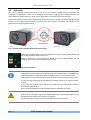
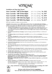
CPC
Compact Professional Charger
Microprocessor controlled battery charger
CPC 1215
CPC 1220
CPC 1230
CPC 1260
CPC 2415
CPC 2420
CPC 2430
CPC 2440
CPC 2450
CPC 2460
User Manual
Ver. 1.0en
LEAB Automotive GmbH
www.leab.eu
LEAB Automotive -CPC
Important information about this documentation
The technical data, information and illustrations have been put together carefully and correspond to the
production status at the time the documentation was prepared.
However, the manufacturer retains the right to improve or modify the products, specifications and
documentation without notice at any time according to technical requirements and the latest
development status.
The descriptions have been prepared in detail and with great care. Nevertheless, errors can never be
ruled out entirely. No liability will be accepted for errors of damage which could originate from these or
from faulty interpretations.
The contents of this documentation may not be copied, reproduced, translated or forwarded to third
parties in any other way without the express permission of LEAB Automotive GmbH .
Caution!
Safety note, non-observance can lead to personal injury or material damage as well as
impair the device function.
Caution! Hazard through electric voltage
Safety note, non-observance can lead to injuries and death as well as damage or destroy
the device.
Note
Supplementary information on how to handle the device.
LEAB Automotive GmbH
Thorshammer 6
D-24866 Busdorf
Germany
www.leab.eu
Important note on using the device
To avoid operational errors, you should read this manual carefully before installation and before initial
use, and always follow the respective instructions. Please keep this manual near the charger for future
reference so that operators can use it to find out about the device's functions.
Page - 2 -
LEAB Automotive GmbH
LEAB Automotive -CPC
Contents
Page
Important note on using the device ..................................................................................................... 2
1.
Scope of supply........................................................................................................................ 4
2.
Performance characteristics and operating functions ........................................................... 5
2.1 Charging procedure.................................................................................................................. 5
2.2
Operation ................................................................................................................................. 6
2.3
Connection............................................................................................................................... 7
2.3.1 Battery in the vehicle ................................................................................................................ 7
2.3.2 Battery outside the vehicle ....................................................................................................... 7
2.4
Power supply function .............................................................................................................10
2.5
Control display and fault descriptions ......................................................................................11
2.6
Troubleshooting ......................................................................................................................12
2.7
Maintenance and service.........................................................................................................13
3.1
Specifications ..........................................................................................................................14
Technical data.........................................................................................................................14
3.2
Dimensional drawing ...............................................................................................................16
4.1
Installation ...............................................................................................................................16
CPC connections ....................................................................................................................17
4.2
Installation location..................................................................................................................17
4.3
Device installation ...................................................................................................................18
4.4
Conversion of charging cable (CPC 600W and 800W only) .....................................................19
4.5
Connection and conversion of the mains connection cable ......................................................19
4.6
Connection of remote display ..................................................................................................20
4.7
Connection of sensor cable .....................................................................................................21
4.8
Connection of CBL control relay (600/800W only) ....................................................................21
3.
4.
Annex A ................................................................................................................................................23
Mains connection plug 230V ...............................................................................................................23
Annex B ................................................................................................................................................24
Use of lead-acid batteries ....................................................................................................................24
Battery maintenance .........................................................................................................................24
Open batteries ..................................................................................................................................24
Sealed batteries ................................................................................................................................24
Battery storage .................................................................................................................................25
Annex C ................................................................................................................................................26
Extent of Warranty ............................................................................................................................26
CE Declaration of Conformity..............................................................................................................27
LEAB Automotive GmbH
Page - 3 -
LEAB Automotive -CPC
1.
Scope of supply
With the LEAB battery charger CPC you have purchased a high-quality battery charger that you can use
both permanently installed in vehicles and in mobile workshop applications. Please check before you
use the charger whether the following items are included in the box:
Battery charger CPC of the required voltage and output (see specifications on the rating plate)
Mains connection cable 230VAC, 1.5 m long, with Schuko plug
Battery charging cable 2x 6/10 mm², 1.5 m long, permanently attached
English manual (this document)
If the scope of supply does not correspond to these items, or the charger or connection cable are
damaged, please contact your dealer or LEAB directly.
If you should require a further copy of the manual, you can download this in PDF format from
www.leab.eu free of charge.
If you should require spare parts or accessories for your LEAB battery charger CPC, please see section
2.7 of this manual and send your order by email to [email protected].
Overview of available types:
To make presentation easier, we distinguish between three series of CPC battery chargers depending on
the capacity of the power supply. The basic properties such as dimensions, weights and electrical
equipment are identical within one such group. Compare the technical data listed in Chapter 3.
Series 600W
Series 800W
Series 1600W
CPC 1215
CPC 1230
CPC 1260
CPC 1220
CPC 2420
CPC 2440
CPC 2415
CPC 2430
CPC 2450
CPC 2460
Page - 4 -
LEAB Automotive GmbH
LEAB Automotive -CPC
2.
Performance characteristics and operating functions
The portable battery charger LEAB CPC has been developed both for mobile use and stationary
installation in vehicles for the charging of all types of lead batteries.
Thanks to their compact design, high capacity and very good interference suppression, LEAB battery
chargers have been used for years wherever optimum mobile battery charging is essential.
Custom charging programs are available for special applications, and also provide a suitable solution for
special applications such as the charging of traction or lithium batteries.
2.1
Charging procedure
Battery charging takes place completely
automatically and controlled by microprocessor with a three-stage IU1oU2 charging
characteristic for optimum and gentle battery
treatment. The charging parameters can be
adapted to the type and capacity of the
batteries to be charged during installation
and before connection to the battery by
selected one of the 15 characteristic curves
stored in the device.
Charging with constant current (I-phase, LED lights up orange)
Depending on the battery's state of charge, maximum charging current is used in order to store as much
energy as possible in the battery as quickly as possible. If an exhaustively discharged battery is
connected for charging, the battery charger starts charging at reduced current to prevent damage to the
battery. After the set main charging voltage has been reached (14.2 (28.4) to 14.4 (28.8) V depending on
the battery type), the battery charger switches to the next charging phase.
Charging with constant voltage (U1-phase, LED lights up orange)
The actual full charging of the battery takes place in this phase. The voltage is kept contact at a value of
14.4 (28.8) V (setting gel/AGM) or 14.2 (28.4) V (setting wet cell). As the battery charge increases the
current drops continually and approaches a lower limit which depends on the type and size of the
battery. As soon as the value drops below this limit or a set minimum charging time has been exceeded,
the battery charger switches to phase 3.
Equalisation charging (U2-phase, LED lights up orange): only with the program for traction batteries
Following the main charging phase, the electrolyte is stabilised, any sulphating of the plates is degraded.
Depending on the battery type set, the voltage increases to up to 15.6 (31.2) V at reduced charging
current. As soon as this phase has been completed the battery charger switches to phase 4.
Maintenance charging with reduced voltage (U3-phase, LED lights up green)
The charging voltage is reduced to 13.6 (27.2) V (setting wet cell) or 13.8 (27.6) V (setting gel/AGM) to
keep the battery fully charged over an unlimited time. Physical self-discharge is compensated and the
battery is kept fully charged until it is disconnected. During the maintenance phase LEAB CPC battery
chargers can operate connected consumers up to the full capacity of the battery charger without any
undesired return to main charging.
The values specified are for 12 V charging setting (values for 24 V in brackets).
LEAB Automotive GmbH
Page - 5 -
LEAB Automotive -CPC
2.2
Operation
The correct charging characteristic must be set on the CPC battery charger before installation and
connection to the battery. There are 15 charging characteristics (and one test setting) stored in the
internal battery charger memory; these can be requested via a 16-level rotary potentiometer.
Use the table on the characteristic sheet (delivered with the battery charger) to choose the appropriate
setting for your application depending on battery type and capacity, and adjust the charger to this
position by turning the potentiometer.
Potentiometer
Fig. 1 Position of the potentiometer and front display
Attach the enclosed sticker in such a way that it covers the setting potentiometer and
the recess is over the multi-colour LED.
Refer to section 2.5 of this manual for details of the LED status display and the
meaning of the colour code of the three-colour LED.
Fig 2 LED status sticker
Choose the correct battery type "Standard" (for wet cell batteries) or "Gel/AGM" (for
sealed lead batteries using gel or AGM technology) from the characteristic sheet.
Your batteries will only be charged perfectly when the correct setting has been made.
See your battery data sheet for information on battery charging, or ask your battery
supplier.
If you have any questions about the correct charge setting, please contact LEAB or
your battery manufacturer.
Other charging programs for special applications are available on request.
If batteries are charged using an unsuitable characteristic, their performance can be
impaired and the battery will not reach its capacity.
The wrong charging characteristic can damage or destroy the battery.
Page - 6 -
LEAB Automotive GmbH
LEAB Automotive -CPC
2.3
Connection
If you want to use the LEAB CPC as a mobile battery charger, please continue with section 2.3.2.
2.3.1 Battery in the vehicle
Connect the two charging cables fixed to the LEAB CPC as follows:
red end of the cable to the plus terminal of the battery (marked +)
black end of the cable to the minus terminal of the battery (marked –) or an earth contact point
provided near the battery.
We recommend the use of a safety fuse in the plus cable with the following values:
Type
Fuse
Crosssection
CPC 1215
30 A
6 mm²
CPC 1220
40 A
6 mm²
CPC 1230
50 A
6 mm²
CPC 2415
30 A
6 mm²
CPC 2420
40 A
6 mm²
Type
Fuse
Crosssection
CPC 2430
50 A
6 mm²
CPC 1260
75 A
10 mm²
CPC 2440
75 A
10 mm²
CPC 2450
75 A
10 mm²
CPC 2460
75 A
10 mm²
The cross-sections of the charging cables must not be reduced. We recommend keeping the charging
cables as short as possible and not extending them.
There are three sockets on the back of the CPC
battery charger (only 2 sockets on the CPC
1600W) which can be used to connect additional
devices (see section 4.6ff). Assignment is as
follows:
Remote display
Temperature/voltage sensor
CBL relay (not CPC 1600W)
2.3.2 Battery outside the vehicle
Connect the two charging cables to the battery terminals as follows:
red end of the cable to the plus terminal of the battery (marked +).
blue end of the cable to the minus terminal of the battery (marked –).
Only use suitable battery terminal clamps and protective pole caps such as the ones you can find in our
range at http://shop.leab.eu.
230V mains connection
There is a connection socket for the 230V mains cable on the back of the CPC battery charger. The plug
system of the type Neutrik can be locked, thus guaranteeing safe and vibration-resistant contact in
every vehicle, yet providing maximum flexibility during installation and removal. Please refer to Annex A
LEAB Automotive GmbH
Page - 7 -
LEAB Automotive -CPC
in this manual for information about attaching and releasing the plug-type connections as well as
assembly instructions for preparing new connection cables.
Starting charging
Connect the mains plug to a Schuko socket in your building installation, thus switching the CPC battery
charger on. After the device has been connected to the mains, the operational LEDs start to flash red for
2 seconds while the battery charger checks whether or not a battery is connected.
If the LED lights up orange, charging is taking place according to the set program.
Never switch the battery charger on until the connection to the battery has been
established. Otherwise a fault message will be issued and the battery will not be
charged.
No charging takes place as long as the red LED lights up or flashes.
Battery voltage 12 V (one battery)
After a few seconds the CPC starts in the selected program and automatically charges the connected
battery until it is fully charged. If the orange setting LED and the red Error LED are flashing alternately
despite correct voltage, please check the battery voltage. If the voltage is less than 8 V the CPC will not
start charging for safety reasons, in order to avoid potential hazards caused by exhaustively discharged
batteries*.
As soon as the battery is fully charged, the LED display changes from orange to green and the charging
voltage is reduced to maintenance charging. The battery can now be disconnected or remain connected
to the battery charger until it is used. The CPC ensures that the battery remains fully charged in the
meantime, independently of the time involved.
* Only with charging program with start voltage > 0 V.
Choose the correct battery type Standard (for wet cell batteries) or Gel/AGM (for
sealed lead batteries using gel or AGM technology). Your battery will only be charged
correctly in this case.
Individual batteries with a voltage of less than approx. 8 V will no longer be charged
in the charging setting of the CPC for safety reasons: Exhaustively discharged
batteries must be pre-charged for several hours using a power supply (charging
program with start voltage 0 V even charges exhaustively discharged batteries).
Page - 8 -
LEAB Automotive GmbH
LEAB Automotive -CPC
Battery voltage 24 V (two batteries in series)
After a few seconds the CPC starts in the selected program and automatically charges the connected
battery until it is fully charged. If the orange setting LED and the red Error LED are flashing alternately
despite correctly set voltage, please check the voltage of the batteries. If the voltage is less than 20 V
the CPC will not start charging for safety reasons, in order to avoid potential hazards caused by
exhaustively discharged batteries*. Please pre-charge the batteries separately. As soon as the battery is
fully charged, the LED display changes from orange to green and the charging voltage is reduced to
maintenance charging. The battery can now be disconnected or remain connected to the battery
charger until it is used. The CPC ensures that the battery remains fully charged in the meantime.
* Only with charging program with start voltage > 0 V.
Choose the correct battery type Standard (for wet cell batteries) or Gel/AGM (for
sealed lead batteries using gel or AGM technology). Your battery will only be charged
correctly in this case.
Depending on the state of charge and size of the battery to be charged, it can take up
to 18 hours for the batteries to be fully charged again.
Batteries which are connected up to 24 V and have been exhaustively discharged to
under 20 V must always be charged individually to avoid any further damage; use a
12 V battery charger for this.
If sealed lead batteries (gel or AGM) are charged for longer periods with excessively
high voltage they can gas and dry out, thus destroying the battery.
Open wet cell batteries consume water during charging. Water must thus be refilled
regularly.
If you are not sure how to charge your batteries, please contact your specialist
dealer.
Discharged batteries must be recharged without delay, otherwise they can be
destroyed.
LEAB Automotive GmbH
Page - 9 -
LEAB Automotive -CPC
2.4
Power supply function
CPC batteries chargers with a charging program with start voltage 0 V* can also be used without a
battery to supply DC consumers up to the maximum capacity of the battery charger. In this case it must
be noted that the output voltage is reduced after a short time from the higher main charging voltage to
the lower maintenance charging voltage.
This allows vehicles to be supplied with voltage even when the battery has been removed, thus avoiding
the time-consuming and tedious re-programming of customer settings in the on-board computer and
radio system.
LEAB can equip all CPC battery chargers with the suitable power supply program* for exclusive use as a
power supply. Please contact LEAB Service in this case.
Charging programs must be stated in your order for the CPC battery charger so that they can be installed
in the battery charger.
* Optional extra
Power supply function is only available for devices with start voltage 0 V or with
special power supply program.
The power supply output is resistant to short-circuit and overload, but longer shortcircuit should still be avoided to prevent the charging cable and LEAB CPC becoming
too hot.
The optional power supply program is also suitable for pre-loading exhaustively
discharged batteries which are no longer detected by a battery charger for a few
hours or for regenerating them.
If you would like to use the LEAB CPC in combination with diode distributors or the
charging current distributor LEAB CDB, you must always choose a charging
characteristic with 0 V start voltage.
Page - 10 -
LEAB Automotive GmbH
LEAB Automotive -CPC
2.5
Control display and fault descriptions
The control lamp (three-colour LED) on the front of the device indicates the different operating and fault
statuses:
The different statuses are indicated by permanent or flashing light. See section 2.2 on the position of the
LED.
LED display on the battery charger
LED
Status
Description
Measure
Permanent light
orange
Battery is being charged, the CPC is in
the main charging phase
none
Permanent light
green
Battery fully charged, the CPC is in the
maintenance charging phase
The battery charger can be unplugged and the
battery used
Permanent light
red
No battery connected or connected
battery exhaustively discharged
Check the battery connection, measure the battery
voltage, pre-charge the battery using the power
supply*
Flashing
red
Time exceeded in the main charging
phase, charging interrupted
Battery faulty: Check battery
Battery too large for the battery charger: choose
larger battery charger
Parallel consumers too large: Switch consumers off
during charging
Table 1: LED display on the CPC battery charger
* Pre-charging is not necessary for programs with start voltage 0 V
LED display on the optional remote display
If you have the optional LED remote display installed (see section 4.5), the CPC statuses will also be
displayed there in the same way as described above.
LEAB Automotive GmbH
Page - 11 -
LEAB Automotive -CPC
2.6
Troubleshooting
If your LEAB CPC is not working as it should, please try to localise the fault using the following procedure
first. If this is not successful, please contact your specialist dealer or LEAB. Have the serial number and
date of purchase on hand as well as an accurate description of the fault so that we can help you as
quickly as possible.
LED display on the battery charger. The figures refer to the corresponding chapters in this manual.
Battery is not being
charged
ye
s
Is the LED lit
green?
- Maintenance
charging - check
voltage
no
Is the LED lit
orange?
ye
s
- Main charging
- Check charging
program (2.3)
- Check battery
voltage
- Battery faulty
no
Is the LED lit
red?
ye
s
no
Lock Neutrik
connector
no
Is the Neutrik
connector
locked?
ye
s
Insert mains plug
no
Is the mains
plug
inserted?
ye
s
Switch the mains
fuse on
no
Is the mains
fuse OK?
ye
s
Contact LEAB
Service
Page - 12 -
LEAB Automotive GmbH
Is the LED
flashing red?
ye
s
- Connect
battery (2.3);
- Check voltage
- Select power
supply
function (2.4);
- Check charging
cable
no
- Connect
battery (2.3);
- Check voltage
- Select power
supply
function (2.4);
- Check charging
cable
LEAB Automotive -CPC
2.7
Maintenance and service
Regular tests
Check the battery charger before every use as follows:
Are the mains cable and mains plug undamaged?
Are the charging cable and connections undamaged?
Is the charging cable fixed safely to the battery charger?
Is the outside of the battery charger undamaged and not opened?
Has the battery charger been in contact with water, oil or other fluids?
When used for commercial applications, the LEAB CPC battery charger is mobile electrical operating
equipment in the sense of the German accident prevention regulation BGV-A3 or is subject to other
regulations of the employers' liability association, depending on deployment and use.
This employers' liability association regulation prescribes the regular testing of electrical devices for
electrical safety (usually once a year). Please clarify with your employers' liability association whether
you are affected by this or any comparable regulation and take the measures necessary for the safety of
your employees.
Your employers' liability association or work accident insurance company will be able to provide more
information.
Check the battery charger and cable for damage before you use the device.
Do not used a damaged device or a device with damaged connection cables; have it
repaired without delay.
Have the device checked if it has been in contact with fluids.
Have the device checked regularly by a qualified electrician.
Always have any necessary repairs done exclusively by LEAB.
Spare parts, accessories
The following spare parts and accessories can be ordered from LEAB Service at [email protected] or in
the LEAB shop at http://shop.leab.eu under specification of the article number:
Pos.
Description
Article number
1
CTS, 2.5 *
1601035593
2
TS, 3.1m*
1601036708
3
CBL set
1601355997
4
Mains cable 1.5 m Neutrik connector / Schuko plug D
1601001122
5
Mains cable 1.5 m Neutrik connector / mains plug CH
1601001123
6
Neutrik connector NAC3FCA blue, single (set)
0205900023
7
Remote display ABC, LED with 5 m cable, RJ45
1401036720
8
Remote display ABC, LED with 12 m cable, RJ45
1401036730
Table 3 Accessories
* also available in other lengths on request.
LEAB Automotive GmbH
Page - 13 -
LEAB Automotive -CPC
3.
Specifications
3.1
Technical data
Model
CPC 1215
CPC 1220
CPC 1230
CPC 2415
CPC 2420
CPC 2430
Article number
0101036900
0101036901
0101036930
0101036902
0101036903
0101036931
Battery
Type of battery
Open and sealed lead acid, lead gel, AGM batteries
Charging characteristic
Rec. battery capacity
Choice of 15 characteristics (see characteristic sheet)
50-150 Ah
60-200 Ah
90-300 Ah
50-150 Ah
60-200 Ah
90-300 Ah
Charging current, maximum
15 A
20 A
30 A
15 A
20 A
30 A
Charging current, permanent
15 A
20 A
30 A
15 A
20 A
30 A
Charging current
Ripple
<3%
Charging voltage
Main charging
14.2/14.4 V
28.4/28.8 V
Equalisation charging*
15.6 V
31.2 V
Maintenance charging
13.6/13.8 V
27.2/27.6 V
Supply voltage (AC)
Input voltage (nominal values)
230 V / 50 Hz / 4 A
Input voltage range
90 … 270 V (< 200 V reduced charging current)
Input frequency range
0 … 400 Hz
Standby current (from the
battery)
< 2 mA
Switching frequency
100 kHz
Recommended mains fuse
protection
B16 A or C16 A
Maximum efficiency
> 88 %
Class of protection
I
Operating temperature range
-30 … +60° C
IP protective rating
IP 20
Housing dimensions
264 x 127 x 86 mm
(length x width x height)
Weight (without cable)
1.5 kg
Connection cable
Twinflex charging cable 2x6 mm², length 1.5 m
Mains cable 1.5 m Neutrik connector / Schuko plug
Weight (accessories)
Charging cable 1.5 m: 0.2 kg / Mains cable 1.5 m: 0.2 kg
Table 4 Technical data CPC 600W/800W
Page - 14 -
LEAB Automotive GmbH
LEAB Automotive -CPC
Model
CPC 1260
CPC 2440
CPC 2450
CPC 2460
Article number
0101036970
0101036971
0101036972
0101036973
Battery
Type of battery
Open and sealed lead acid, lead gel, AGM batteries
Charging characteristic
Rec. battery capacity
Choice of 15 characteristics (see characteristic sheet)
150-600 Ah
120-400 Ah
140-500 Ah
150-600 Ah
Charging current, maximum
60 A
40 A
50 A
60 A
Charging current, permanent
60 A
40 A
50 A
60 A
Charging current
Ripple
<3%
Charging voltage
Main charging
14.2/14.4 V
28.4/28.8 V
Equalisation charging*
15.6 V
31.2 V
Maintenance charging
13.6/13.8 V
27.2/27.6 V
Supply voltage (AC)
Input voltage (nominal values)
Input voltage range
Input frequency range
230 V / 50 Hz / 8 A
90 … 270 V (< 200 V reduced charging current)
0 … 400 Hz
Standby current (from the
battery)
< 2 mA
Switching frequency
100 kHz
Recommended mains fuse
protection
Maximum efficiency
B16 A or C16 A
> 88 %
Class of protection
Operating temperature range
I
-30 … +60° C
IP protective rating
IP 20
Housing dimensions
294 x 135 x 95 mm
(length x width x height)
Weight (without cable)
Connection cable
2.2 kg
Twinflex charging cable 2x10 mm², length 1.5 m
Mains cable 1.5 m Neutrik connector / Schuko plug
Weight (accessories)
Charging cable 1.5 m: 0.2 kg / Mains cable 1.5 m: 0.2 kg
Table 5 Technical data CPC 1600W
* EQ charging only with charging characteristic for traction batteries (option)
LEAB Automotive GmbH
Page - 15 -
LEAB Automotive -CPC
3.2
Dimensional drawing
Fig. 3 Dimensions CPC 600W/800W (left) and CPC 1600W (right)
4.
Installation
The LEAB CPC has been designed primarily as a built-in battery charger but it can also be used as a
transportable service battery charger. The sturdy rubber corners make stable yet vibration-absorbing
attachment possible, allowing it the be set down or mounted to sensitive surfaces without causing any
damage.
However, since the charging cables do not have an additional strain relief fixture, we recommend
changing to the type LEAB PWC if you wish to use the device permanently as a service battery charger.
The device feet have suitable seats for attachment bolts for permanent installation, allowing the CPC to
be attached vertically or horizontally to a wall or table (see section 4.2).
Page - 16 -
LEAB Automotive GmbH
LEAB Automotive -CPC
4.1
CPC connections
Neutrik
connection
230V
+
-
+
-
Connection
plus
charging
cable
Connection
minus
charging
cable
RJ45
connection CBL
relay (not
1600W)
RJ45
connection
sensor cable
RJ45
connection
remote display
Fig. 5 View of CPC from the back, connection side
4.2
Installation site
The following environmental conditions must be given if you want to install the battery charger for
stationary use:
Choose a dry and dust-free spot, not too hot, for installation.
The LEAB CPC can be attached horizontally to a level panel as well as horizontally or
vertically to a wall.
Optimum cooling is achieved with the LED side facing downwards.
Make sure there is sufficient and unobstructed cooling air flow so that the heat
produced can be dissipated safely.
Do not install the device directly next to or above inflammable materials.
Never install the battery charger in the direct vicinity of open wet cell batteries. The
acid vapours produced during charging can corrode and thus destroy the PCB and
other components.
Do not use a charging cable with a cross-section smaller than the one delivered with
the device.
Protect your battery charger from excessive heat impact. This reduces performance
and can shorten the service life.
Heed the installation guidelines for other devices (e.g. radio-controlled devices) to
avoid mutual influence.
Never charge with the charging characteristic set incorrectly. The battery can
become damaged.
LEAB Automotive GmbH
Page - 17 -
LEAB Automotive -CPC
Dry, well ventilated and dust-free installation location.
Keep the distance to the batteries as short as possible to achieve short cable lengths.
Do not install the device directly next to or above the batteries.
The device must be protected from the effect of dust and humidity.
Make sure that the fan can intake cooling air freely.
Do not install the device directly next to or above inflammable materials.
4.3
Device installation
Install the device on a level horizontal or vertical surface. The four recesses on the rubber feet are for
attachment. Use screws with a diameter of 5 mm.
The built-in fan guarantees optimum cooling independently of the direction of
installation.
Dimensional drawings can be found in section 3.2.
Vertical installation option
Attachment screws 5
mm
Fig. 5 Attachment CPC
Page - 18 -
LEAB Automotive GmbH
LEAB Automotive -CPC
4.4
Conversion of charging cable (CPC 600W and 800W only)
Depending on the application, it can be necessary to replace the charging cable fitted to the LEAB CPC.
This can be due to cable damage or in order to fit a cable of a different length than the one already
fitted. Standard electric cables of the corresponding cross-section can be used as replacement cables.
To remove the charging cable, disconnect the LEAB CPC from the mains and from the battery. Use a slim
screwdriver to carefully release the two clamp locking mechanisms on the cable terminals which are
used to attach the charging cables to the charging output and pull the old charging cables out.
Push the stripped ends of the new charging cables completely into the terminal guides. To do this, twist
the ends of the wires slightly and release the locking mechanism using a screwdriver before pushing the
ends in. Pull the screwdriver out when the cables have been pushed in completely so that the locking
mechanism can grip tightly. Pull the new charging cable firmly a few times to check whether the locking
mechanism holds.
Note the polarity specifications on the label next to the charging output. Connect the red charging cable
to the left-hand output marked + and the blue or black charging cable to the right-hand output marked
–.
4.5
Connection and conversion of the mains connection cable
When the LEAB CPC is mounted on the wall or used as a transportable battery charger, the 1.5 m mains
connection cable delivered with the device may not always be sufficient and may need replacement. To
make this modification easier for you, the mains connection cable is connected to a Neutrik connector
system. See Annex A of this manual for instructions on fitting the Neutrik connector.
To insert and remove the mains connection cable to and from the battery charger, please proceed as
follows:
separation
engagement
Engagement
Separation
Insert the blue Neutrik connector on the mains cable
into the jack on the back (connection side) of the
LEAB CPC (1) and turn the connector clockwise (2)
until you hear a quiet click indicating successful
locking.
Pull the silver locking lever (1) towards you and turn
the connector anti-clockwise (2) as far as it will go
until you can pull the connector out of the jack (3).
LEAB Automotive GmbH
Page - 19 -
LEAB Automotive -CPC
If you require a longer mains connection cable or one with a plug other than the 250 V/16 A Schuko plug
delivered with the device as standard, please contact LEAB or your specialist dealer. We can make
customised connection cables for you at a favourable price. We expressly advise against modifying the
connection cable yourself, fitting other plugs or making new cables.
The respective national guidelines (e.g. VDE, DIN in Germany) or guidelines from the associations
responsible (accident prevention regulations for example) must be followed when connecting the device
to an existing 230 V installation. This work may only be carried out by an appropriately trained
electrician. The LEAB CPC corresponds to protection class I and requires a protective earth conductor to
be connected. For permanent installation we recommend a cable cross-section of 3x 1.5 mm².
4.6
Connection of remote display
There is also an LED remote display optionally available from
LEAB for connection to the RJ45 jack on the back of the
device (refer also to the drawing in section 4.1). This remote
display can be used to display the status of the built-in LED,
providing an additional display of the status of charge and
charging parameters for a permanently installed battery
charger.
Refer to section 2.5 for details of the display and appearance
of different LED states.
Fig. 6 Remote display with connection cable
Page - 20 -
Article number and type for the remote display can be found
in the spare parts and accessories list in section 2.7 of this
manual.
LEAB Automotive GmbH
4.7
LEAB Automotive -CPC
Connection of sensor cable
There is also two sensor cables optionally available from LEAB for connection to the RJ45 jack on the
back of the device (refer also to the drawing in section 4.1).
CTS cable: Sensor for temperature and voltage
This sensor cable is used to measure the temperature in the battery
environment as well as the voltage directly at the battery terminal,
and then transmit this to the CPC battery charger. The CPC corrects
the charging voltage depending on the temperature, in order to
achieve optimum efficiency and yet gentle battery charging at all
times, no matter the temperature. By measuring the voltage at the
battery terminals, the CPC can compensate the drop in voltage on the
charging cable, thus making faster and more efficient charging
possible even with long charging cables.
We recommend the use of the combined CTS sensor cable where
charging cables longer than 3 m are used.
TS cable: Sensor for temperature
This sensor cable can be used to measure the temperature in the direct
environment of the battery and transmit this to the CPC battery
charger. The CPC corrects the charging voltage depending on the
temperature, in order to achieve optimum efficiency and yet gentle
battery charging at all times, no matter the temperature.
We recommend the use of the TS temperature sensor cable where
charging cables up to 3 m in length are used. Available versions can be
found under "Accessories" in section 2.7.
4.8
Connection of CBL control relay (600/800W only)
There is a potential-free changeover contact installed in the battery
charger versions of the LEAB CPC series 600W and 800W which
switches during charging operation. There is a suitable adapter cable
set with RJ45 connector and three open cable ends available for more
straightforward connection.
This option can be used for example as an electrical ignition interlock
for a 230 V connection or for charging monitoring.
Fig. 7 Connection assignment and technical data for switched output CBL
LEAB Automotive GmbH
Page - 21 -
LEAB Automotive -CPC
General notes
The charging output is short-circuit-proof: no hazardous state occurs for the device
even when the charging cable is connected directly.
The charging output is protected against inverse polarity: the battery or the CPC will
not be damaged if you mix up the battery connections; charging is not possible with
inverse battery connections.
Sparks can fly if the charging cable is connected to a battery with the battery charger
switched on.
Make sure there is a good electrical contact, clean the battery terminals before
connection if necessary.
All-round rubber edges protect any sensitive surfaces the device is set down on. Keep
the rubber feet in particular clean of dirt and solvents so that this protection effect is
not jeopardised.
Always connect the charging cables to the battery terminals first before you connect
the device to the mains in order to avoid sparking.
Always select the charging program to match the type and size of battery on the CPC;
the wrong selection can lead to the battery not being charged correctly or becoming
damaged due to excess charge.
Protect the battery charger from water and humidity.
Check the battery charger regularly for damage and replace any faulty or worn
connection cables immediately.
Do not open the device, there are no components the user can operate inside the
device.
Clean the device feet regularly and do not expose them to acids, oil and aggressive
cleaning agents.
When charging refillable lead-acid batteries open the cover so that any gases
produced can escape.
Clean the air inlets and outlets regularly if heavily soiled.
Page - 22 -
LEAB Automotive GmbH
LEAB Automotive -CPC
Annex A
Mains connection plug 230V
The following non-interchangeable connector is used for the 230V mains connection cable:
AC input connector, type Neutrik NAC3FCA – blue
The connector is available as a spare part from LEAB under the article number 0205900023.
Operation of Neutrik connector
separation
engagement
Fitting the Neutrik connector
A-type coding (blue)
Cable preparation
Sleeve
Insert
Clamping piece
LEAB Automotive GmbH
Connections
Union nut
Page - 23 -
LEAB Automotive -CPC
Annex B
Use of lead-acid batteries
Handling lead-acid batteries can be hazardous. These batteries produce explosive
gases.
If metal tools are used for work on batteries, it is important that the plus and minus
terminals can never be touched at the same time.
A short-circuit through a solid metal tool can lead to the battery exploding. If acid
splashes onto the skin and eyes in particular, rinse the parts affected with clear water
and seek medical advice immediately.
The installation location for batteries must be well ventilated.
Smoking and naked flames are prohibited during work on batteries.
Regular recharging and maintenance will extend the service life.
Battery maintenance
Lead batteries, including ones which are not currently in use, must be recharged and serviced regularly.
This should take place at least once a month during the warm seasons and every three months in the
cold seasons. Older and poorly maintained batteries should be checked every two weeks.
Open batteries
The fluid level in open batteries should be checked, and the acid density measured using an acid siphon.
They must be recharged if necessary.
A clean and dry battery surface will lead to a longer service life. Soiling and any acid marks should be
removed carefully. This can be done using warm water and a soda solution. Then rinse off with clear
water and dry carefully. Make sure that the ventilation caps have been fitted cleanly and correctly.
In addition, the connection terminals must be checked for a tight fit. The terminal screws should always
be tightened.
Make sure that the cell grids are covered with acid. Only distilled water may be used for topping the
battery up. Never use normal drinking water.
Do not fill up with too much water, this would reduce the acid density and thus the battery capacity
(heed manufacturer instructions).
Sealed batteries
Sealed batteries are low-maintenance. The acid is bound through gel or in a fleece (AGM) and can
therefore not evaporate. Testing is limited to measuring the battery voltage.
To achieve a plausible result, the battery must not have been charged for several hours prior to testing.
However, simply testing the voltage is not necessarily sufficient, since sulphating can increase voltage
even if capacity is reduced. More accurate conclusions can only be drawn by using a suitable battery
tester e.g. Midtronix MDX for tests.
Page - 24 -
LEAB Automotive GmbH
LEAB Automotive -CPC
Summary of maintenance points:
Make sure that batteries are always fully charged (only use suitable high-quality battery
chargers such as LEAB CPC). Do not part-charge batteries if possible.
Regular charging reduces the risk of irreversible, permanent sulphating.
Open wet cell batteries must be topped up regularly using distilled water.
Battery surface and terminals must be dry and clean.
The connection terminals must be covered with terminal grease.
Do not expose batteries to a hot environment.
Check the connection terminals for a tight fit at least once a year.
Replace any batteries which bulge, are cracked or leaking.
Battery storage
Store batteries in a cool but frost-free and dry environment.
Never store batteries in a discharged state. They should be charged to at least 75%.
If batteries are stored for longer periods, check their state of charge at regular intervals and
recharge if necessary.
In very cold environments continuous maintenance charging prevents the battery freezing.
LEAB Automotive GmbH
Page - 25 -
LEAB Automotive -CPC
Annex C
Extent of Warranty
Providing installation has been carried out professionally and the devices are used according to their
intended purpose, LEAB offers mandatory warranty over a period of 24 months after the date of
purchase.
If any defects of faulty functions should occur during this period under normal conditions of use, LEAB
will either repair the device free of charge or replace it at their own discretion. New or repaired parts of
equal value can be used for replacement.
A warranty claim cannot be recognised under the following circumstances:
The device was not used in accordance with the recommendations given in this manual.
The device was used for purposes other than general automotive, solar, industrial or maritime
applications without prior agreement with LEAB.
The device was repaired or modified without express permission from LEAB.
The device shows signs of damage caused by excess charge, penetration of humidity (water, oil,
acid), mechanical force, excess or insufficient voltage or any other non-intended use.
Pre-conditions for warranty payments
Warranty claims can be made to your specialist dealer or LEAB directly. The following documents are
required:
Invoice or delivery note
Model description or type
Serial number
Detailed description of the fault and installation, if appropriate
Procedure
If the device cannot be put back into operation perfectly according to the instructions in this manual or
if the fault persists, contact your dealer's Service department or LEAB directly.
If this is no help either, please request a processing form and processing number (RMA number) as well
as a free UPS pick-up sticker (free UPS pick-up service unfortunately only possible without Germany) by
calling +49 (0)4621 - 97860-120 or sending a mail to [email protected]. You can send the defective device
to us together with these documents. We will then examine it and repair it if necessary.
Page - 26 -
LEAB Automotive GmbH
LEAB Automotive -CPC
CE Declaration of Conformity
The product
LEAB CPC
with the types
CPC 1215, CPC 1220, CPC 1230, CPC 1260
CPC 2415, CPC 2420, CPC 2430, CPC 2440, CPC 2450, CPC 2460
complies with the requirements of the directives 2006/95/EC, 2004/104/EC and 2005/83/EC.
The following harmonised standards were used:
EN 60335-2-29:1996 + A11:97 (IEC335-2-29:2002 modified)
EN 60335-1:1994 + A11:95 + A1:96 +A12:96 + A13:98 + A14:98 + A15:00 + A2:00 + A16:01
as well as
EN 61204-3:2000
EN 50366:2003 + A1
Busdorf, 01.07.2013
Bart Westerkamp
Managing Director
LEAB Automotive GmbH
Page - 27 -
LEAB Automotive -CPC
LEAB Automotive GmbH
Thorshammer 6
D-24866 Busdorf
Germany
Fon: +49 (0)4621-97860-110
Fax: +49 (0)4621-97860-260
Email: [email protected]
www.leab.eu
LEAB is certified to ISO 9001:2008 and 14001:2004
Page - 28 -
LEAB Automotive GmbH