1
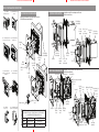
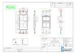
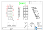
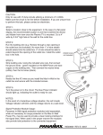
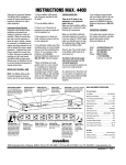
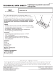
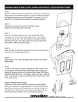
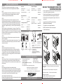
NOTE: DO NOT PRINT RED LINES.
DASHED LINES SHOW FOLD PLACEMENT.
MIW-XT
MIW-XT SPECFICATIONS
MIW-XT INSTALLATION INSTRUCTIONS
CAUTION:
Only for use with 15 Amp branch circuits utilizing 14 or 12 gauge
wire. Make sure the branch circuit is de-energized before installation.
NOTE:
The type of installation and outlet box will determine which components
are used. The MIW mounting ears will only be attached on old work
installations using the Raco 508 electrical box.
STEP 1:
Determine which signal line and outlet box configuration you will be
using before beginning installation, as it may affect which components are
installed. The kit can be used with the included MIW Pass-Through Insert
or with a variety of signal line products (sold separately): Panamax signal
line modules, Keystone inserts (fig.1), or Decora® signal line inserts (fig.2).
STEP 2:
Select a location close to the equipment. In the case of a Plasma TV, this
may be behind the display device and be totally hidden from view, once the
Plasma TV is mounted. Cut a 3 3/4” wide by 3 3/4” high hole in the wall for
the outlet box. (When using mounting ears, cut a 4 1/8” wide by 4 1/4” high
hole in the wall for the outlet box).
AC Circuit
Power Inlet Faceplate
AC Outlets, Total: .............................1
AC Connector: .....................IEC 320 C14
Line Voltage: ....................120V, 60Hz
Signal Line Protection: .......Not Included /
Total Current Capacity: ................15A
Modules Sold
Separately
IEC Power Inlet Cord
Length: ......................................6 feet
Connectors: ....................IEC 320 C13
NEMA 5-15P
Flat Plug AC Power Cord
Length: ................................11 inches
Connectors: ...................NEMA 5-15P
SCREEN PRINT ART FOR FRONT OF PFP MIW-POWERKIT-PFP INLET FACEPLATE (TWISTLOCK RECEPTACLE)
PART NO. TFP00848_INLET REV. A
NEMA 5-15R
4-1-2008
DO NOT PRINT RED LINES, FOR PLACEMENT REFERENCE ONLY
INK COLOR - PMS WARM GRAY 9
One each In-Wall power inlet and
outlet enclosure
STEP 5:
Strip AC wire (e.g. Romex) and connect using the included wire nuts. First
connect the ground wire (green insulated) on the Max In-Wall and bare
copper on the building wire. Then connect the neutral wire (white), then the
hot wire (black).
STEP 6:
Run the signal line(s) through the low-voltage signal bay.
If using the MIW Pass-Through Insert (fig. 7), remove the rubber grommet
and cut a hole in the rubber grommet so that it fits snugly around the signal
line. Pass the signal line through the signal bay, place the rubber grommet
over the signal line, and put the rubber grommet back in place.
Optional Signal Protection Module Usage:
Panamax In-Wall signal protection modules (fig. 8) may be used to provide
a clean looking interface for the signal lines.
Installation Instructions
• Power and signal lines are hidden in the wall or behind panel displays
for a clean, tidy and professional installation.
• Extend Connected Equipment Policy to remote equipment when
used with Panamax/Furman Power Management components.
Power Outlet Faceplate
AC Connector: ......................NEMA 5-15R
• Ultra-thin profile can allow equipment to hang less than one inch
from the wall.
Noise Filtration: .............................Level 1
• Accommodates optional MIW Signal Line Modules
Signal Line Protection: .......Not Included /
Modules Sold
Separately
CONTENTS*
(Side
View)
(MIW modules sold separately).
• CSA certified for code compliant installations.
• EMI/RFI noise filtration built into outlet receptacle.
• 3 Year Product Warranty.
(Back
View)
FRONT SIDE
VIEW VIEW
BACK
VIEW
Kit Includes Components for Four Possible Installation Configurations:
PLUG
SECURING
CLIP
STEP 3:
Run the source wire (e.g. Romex) through an opening in the outlet box
(both sold separately).
No more than 1” of wire sheath should extend into the outlet box. 3” of wire
should be able to extend beyond the opening of the outlet box. Install the
outlet box into the hole.
STEP 4:
Attach the mounting bracket to the outlet box (fig. 4).
If not using a dual-gang, divided outlet box, you will need to attach the
Decora assembly or module bay assembly to the mounting bracket (fig.
3) using the #6-32 nuts and lock washers before installing the mounting
bracket to the wall. If using a dual-gang outlet box, the nuts and washers
will need to be removed.
MAX IN-WALL™ POWER MANAGEMENT EXTENDER SYSTEM
11” flat plug adapter
power cord (1)
MIW PassThrough Insert
(2)
Decora®
adapter (2)
Keystone
module insert
(2)
6’ IEC power cord &
securing clip (1)
(6) Wire Nuts, 14/14 and 12/14 AWG solid wire
compatible
(8) #6-32 8mm Flat Head Philips Faceplate Screws
(8) #6-32T Pan Head Mounting Screws - Philips
(2) Mounting Brackets
(4) Mounting Bracket Ears
(4) #2.6-28T screws for Mounting Post
(4) #6-20T screws for Mounting Bracket Ears
(1) Mounting Template
1.
2.
3.
4.
* Installation options will determine which parts are used. Not all components will be utilized.
QUESTIONS ABOUT PF POWER PRODUCTS?
Customer Relations
PFPower by Panamax~Furman
7:30 AM – 4:30 PM,
1690 Corporate Circle
M-F, Pacific Time (PST)
Petaluma, CA 94954
Email - [email protected]
Phone - 707-283-5900 or 800-472-5555
Fax - 707-283-5901
Web - www.panamax.com or www.furmansound.com
© 2009 PFPower is a Trademark of Panamax, Inc
Max In-Wall is a Trademark of Panamax, Inc
Decora® is a Registered Trademark of Leviton Manufacturing Co, Inc.
1690 Corporate Circle, Petaluma, CA. 94954
www.panamax.com or www.furmansound.com
Signal line module bay provides variety of optional installation solutions by using:
1. Decora® adapter • Trim plate to accommodate a variety of audio/ video
connections.
2. Pass-through insert • For Keystone adapter or rubber grommet.
3. Keystone 2-port adapter • For flexible connection capability.
4. MIW Signal Line Modules
• MIW-5RCA • MIW-VGA • MIW-SVIDEO • MIW-DATA
(MIW modules sold separately, contact Panamax/Furman)
INS00848 REV C 03/09 1
NOTE: DO NOT PRINT RED LINES.
DASHED LINES SHOW FOLD PLACEMENT.
MIW-XT INSTALLATION INSTRUCTIONS
fig. 1 MIW-XT
With Keystone insert
fig. 2 MIW-XT With Decora
adapter
®
PASS THROUGH CONFIGURATION
DECORA CONFIGURATION
New work installation using signal bay and Carlon
SC200DV plastic electrical box.
Installation using Decora adapter and Carlon
B114R electrical box.
Electrical box
(not included)
Decora® Decora® 6-port
trim plate
insert
adapter
(not included)
fig. 3 Mounting Bracket with fig. 4 Mounting Bracket
and wall cut-out
keystone module insert option
Retaining
Clip
Mounting
Bracket
Rubber
Grommet
fig. 6 Rear of MIW-XT
showing wire pigtails
Electrical box
(not included)
Faceplate
IEC Cord
fig. 5 Mounting Bracket
installed, rear view showing
mounting ears
Mounting
Bracket
Electrical box
(not included)
Low-voltage
signal bay
MIW Pass-Through
Insert
#6-32 counterMounting
sunk screw
Bracket
(not included)
®
®
Decora Decora 6-port
Faceplate
insert
trim plate
adapter (not included)
KEYSTONE CONFIGURATION
Faceplate
#6-20 screw
Retaining
Clip
IEC Cord
Installation using Keystone insert and Raco 508
(or 8500) electrical box.
Mounting Post
Mounting Ear
Electrical box (not included)
#2.6-28
screw
Faceplate
Keystone
Module #6-20
Insert screw
Mounting Mounting Electrical box (not
Post
Ear
included)
#2.6-28
screw
fig. 8 Panamax Max In-Wall
Signal Line Protection Module
MIW Pass-Through
Insert
Installation requires use of an outlet box or boxes that are NOT
provided with the product. Product has been tested thoroughly to
be compatible with the following outlet boxes:
Plastic:
Metal:
NEW WORK
Carlon SC200DV
Raco 8355
OLD WORK
Carlon B114R
Raco 508 (hardware removed)
Low-voltage
signal bay
INSTALLATION ALERT
fig. 7 MIW PassThrough Insert
INSTALLATION ALERT
Rubber Grommet
Faceplate
Keystone MIW Pass- Mounting
Bracket
Module
Through
Insert
Insert
Retaining
Clip
IEC Cord
MIW Pass- Mounting
Through Insert Bracket
Low-voltage
signal bay