1
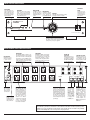
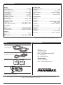
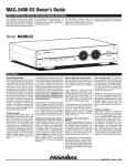
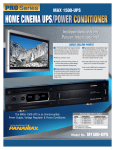
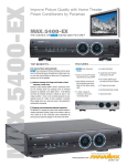
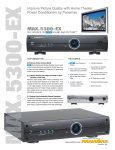
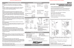
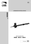
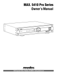
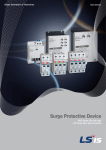
MAX® 5300-EX Owner’s Guide
LEVEL 4 EMI/RFI Noise Filtration with Isolation Between Outlet Banks:
Your audio/video components are constantly
being bombarded by electromagnetic interference (EMI) and radio frequency interference
(RFI) through their power cords. This contaminated power can affect audio/video equipment
and will degrade the overall performance of
your entire system. Common symptoms of
contaminated power include pops, hisses,
hums and visual artifacts.
The MAX 5300-EX is designed to filter this
noise, supply clean power to your system and
provide noise isolation between the outlet so
that any noise created by an A/V component
can not contaminate the power going to equipment plugged into the other outlet banks.
Model: M5300-EX
M5300-EX
BANK 1
ALWAYS ON
BANK 2
ON
VOLTS
BANK 3
ON
WIRING
OK
METER
LIGHTS
Home Theater
ner
Power Conditio
ION
ER AND FILTRAT
POW
Key Features
Sequential Startup/Shutdown:
Complex audio/video systems may be susceptible to voltage transients generated internally
at start-up/shutdown if all of the equipment is
powered on or off at the same time. This can
cause speaker “thumps” which are not only
annoying but can also damage the speakers.
The MAX® 5300-EX is designed to eliminate
these transients by providing a “start-up” delay
for the High-Current outlets and a “shutdown”
delay for the Switched Outlet Bank. This allows
the components plugged into the Switched
Outlet Bank to power-up and stabilize before
any amplifiers and powered sub-woofers are
turned on. This sequence is reversed during
shutdown. The amplifiers and powered subwoofers turn off, their power supplies drain,
and then the equipment plugged into the
Switched Outlet Bank is turned off.
Voltage Sense Trigger:
This feature provides an ON/OFF trigger for the
MAX® 5300-EX using a Direct Current voltage
signal. Many components such as pre-amplifiers and receivers have a DC trigger built in,
and will transmit a constant power signal when
turned on and in use. The presence of this
power signal will turn on the MAX® 5300-EX’s
switched outlets. When the source component
is turned off, the voltage trigger signal is also
turned off and the MAX ® 5300-EX’s shutdown
sequence is initiated. An AC Adapter of the
appropriate voltage, plugged into a switched
outlet, may also be used if a DC trigger is not
built in.
The MAX® 5300-EX voltage sense trigger input
uses a standard 3.5mm (1/8") mini-plug jack.
This jack has an electrically isolated switch built
in. If nothing is inserted into the input jack, the
voltage sense is bypassed and the Power
Button on the front panel has sole control of the
startup/shutdown sequence. If a plug is inserted into the input jack, the front panel switch is
bypassed and the voltage sense becomes the
startup/shutdown trigger. IMPORTANT, Please
Note: The unit needs to be plugged in, and in
the powered OFF state before inserting the DC
input trigger mini-plug.
Automatic Over & Under Voltage Protection:
Panamax’s patent pending power monitoring
circuitry constantly monitors the AC line voltage for unsafe voltage conditions such as prolonged over-voltages and under-voltages
(brownouts). These unsafe conditions pose a
very dangerous threat to all electronic equipment within the home. If the MAX® 5300-EX
senses an unsafe power condition, it will automatically disconnect your equipment from the
power to protect equipment from damage.
Once the voltage returns to a safe level, the
MAX® 5300-EX will automatically reconnect
the power.
Protect or Disconnect AC Surge Protection:
When the MAX® 5300-EX is subjected to a
high voltage surge, its voltage output is limited
to a safe level and the high levels of surge current are diverted away from the connected
equipment.
• When subjected to a 6,000V (open circuit
voltage) / 500A (short circuit current) surge,
the MAX® 5300-EX limits its voltage output to
less than 330V peak, UL’s best rating. The
MAX® 5300-EX will withstand, without damage, 20,000A surges, far exceeding the UL
requirement of only 3000 Ampere surges.
• If the magnitude of the surge is greater than
the capacity of the surge protection components, the MAX® 5300-EX's Protect or
Disconnect‘ Circuitry will disconnect your
equipment in order to protect it. The MAX®
5300-EX will need to be repaired or replaced by
Panamax if this occurs.
Application Specific Coaxial Signal Line
Protection:
Panamax's exclusive SignalPerfect™ Technology provides application specific protection for
your satellite and cable TV equipment. Two
lines of protection are provided for each type.
The satellite connection is for a coaxial cable
connected to a DBS (single or dual LNB) satellite dish. The antenna connection is for a nonamplified off-air antenna or cable TV line.
The protection circuitry has been optimized for
each application and is not interchangeable.
The jacks are not labeled In and Out. The circuitry is bidirectional in both signal transmission and protection capabilities, making it compatible with the latest digital cable and satellite
technologies.
Cable TV (Including HDTV) – TV tuners operate at approximately 10 millivolts (0.01 V) and
utilize the frequency spectrum up to 950 MHz.
The clamping level of the MAX® 5300-EX's
cable TV protection circuitry is 1400 millivolts
(1.4 volts). That's less than 1 volt above normal operating levels. The circuitry is also
shielded to prevent interference.
Satellite TV - Satellite dish LNB's can require
up to 24 volts to operate and utilize the frequency range of 950 MHz to 2.2 GHz. The
clamping level of the MAX® 5300-EX's satellite
protection circuitry is 25 volts - just 1 volt
above the maximum operating voltage. The
circuitry is also shielded to prevent interference.
Telephone Line Protection:
Digital video recorders and satellite TV
receivers require a telephone line connection
for TV show scheduling and/or Pay-Per-View
services. The MAX® 5300-EX also provides
surge protection for this line. One pair of RJ11 telephone jacks is provided for this. The circuitry utilizes auto-resetting PTCRs and solidstate SIDACtors“ for reliability and unsurpassed protection. The clamping level of the
MAX 5300-EX's telephone protector is 260
volts. This will allow typical ring voltage (90130VAC) and operating battery voltage (-48DC)
to pass through the circuit and still protect the
modem in your satellite receiver from damage.
INS0786E Rev A 5/05
M5300 -EX Front Panel Features
Convenience
Outlet
Power Button
Press and hold for 2 seconds to turn Bank 2 and
Bank 3 outlets ON or OFF.
This switch is bypassed if
the rear panel DC Trigger
input is being used.
Power LEDs
Wiring OK LED
Indicates the status of the rear panel
outlets. LEDs for each outlet bank
will be lit when the outlets are turned
ON. They will flash during the startup and shutdown process.
Normally On. Indicates
that the wall outlet is
properly grounded and
Line/Neutral polarity is
correct.
Meter Dimmer
Pushbutton control for
meter LED brightness.
Cycles between Off,
Low, Medium and High.
Provides a quick convenient way to plug in
components such as
camcorders and video
game systems.
Voltmeter
Digital LED voltmeter indicates incoming
line voltages between 90–140VAC.
M5300-EX
VOLTS
BANK 2
ON
BANK 1
ALWAYS ON
BANK 3
ON
WIRING
OK
METER
LIGHTS
POWER AND FILTRATION
Home Theater Power Conditioner
Unsafe Voltage Indicator
Normally Off. Flashes to indicate that the incoming
line voltage is unsafe and the unit has disconnected the power to protect your equipment.
M5300 -EX Back Panel Connection Features
BANK 2
CD
RECEIVER
BANK 3
Satellite TV
Coax Jacks
Cable TV Coax Jacks
Bidirectional protection circuit optimized for satellite
TV signal lines. Do not use
for cable TV off-air antennas and cable modems.
Bidirectional protection circuit optimized for cable TV,
off-air antennas and cable
modem signal lines. Do not
use for Satellite TV.
BANK 1
SATELLITE
DVR
15 AMP CIRCUIT
BREAKER
Four always on outlets. Power will only
be turned off under a fault condition.
(See specifications for over-voltage and
under-voltage thresholds) Power is
cleaned by a three-stage balanced Pi filter which also provides noise isolation
from Outlet Banks 2 and 3.
HDTV / MONITOR
Automatically opens
when the current load
is greater than 15
Amps. Push to reset.
Outlet Bank 1
Four switched outlets controlled by the
front panel Power Button or the DC Trigger
input. Bank 2 will turn on immediately and
turn off after 10 seconds. EMI/RFI noise filtration is provided by a three-stage balanced
Pi filter which also provides noise isolation
from Outlet Banks 1 and 3.
AUX / VCR
Circuit Breaker
Outlet Bank 2
SATELLITE 1
CATV / ANT
CATV / ANT 1
SATELLITE 2
CATV / ANT 2
GROUND
LUG
MAIN POWER
120 VAC/15A
HIGH CURRENT
SWITCHED
DIGITAL RADIO
HD CABLE / SAT
PRE-AMP
DVD
SUB / AMP
DELAY ON
ALWAYS ON
LAN
VOLTAGE SENSE
TRIGGER INPUT
LINE IN
EQUIP.
PHONE
LINE IN
EQUIP.
3 - 24VDC
Main Power
Outlet Bank 3
Voltage Sense Trigger Input
LAN Jacks
Phone Jacks
Must be plugged
into a properly
wired & grounded 3-wire outlet
Two switched, high current
outlets controlled by the
front panel Power Button or
the DC Trigger input. Bank 3
has a 5 second turn on delay
and turns off immediately.
The High Current outlets provide power from a low
impedance noise filtration
circuit that does not limit the
current to your equipment.
Its output is noise isolated
from all other outlet banks.
3.5mm (1/8”) Mini-Plug jack.
Connect to a remote trigger device
that uses a DC output to trigger a
startup/shutdown sequence. This
bypasses the front panel power
switch. Important, Please Note:
The unit needs to be plugged in,
and in the powered OFF state
before inserting the DC input trigger mini-plug.
Protection circuits
for 10/100 baseT
Ethernet
lines.
Incoming LAN line
MUST be plugged
into the LINE jack.
Patch cord to the
equipment MUST
be plugged into
the EQUIP jacks.
Protection circuits for
standard telephone or payper-view lines. Phone circuit is auto-resetting.
Incoming phone cord
MUST be plugged into the
LINE jack. Patch cords to
the equipment (satellite
receiver, digital video
recorder, telephone, etc.)
MUST be plugged into the
EQUIP jacks.
Ground Lug
Provides a common
grounding point for
equipment with separate ground leads.
Note to CATV Installers:
This reminder is provided to call attention to Article 820-40 of the NEC. That article provides specific
guidelines for proper grounding.It specifies that the cable ground shall be connected to the grounding
system of the building and as close to the point of entry as practical.
M5300-EX Specifications
AC Power
Line Voltage:..............................................................................120V, 60Hz
Total Current Capacity:.........................................................................15 A
UL1449 Suppression Rating:..............................................................330V
Protection Modes:.................................................................L-N, L-G, N-G
Initial Clamping Level:.........................................................................200V
Energy Dissipation:..................................................................1815 Joules
Peak Impulse Current:............................................................73,000 Amps
Catastrophic Surge Circuit:....................................................................Yes
Thermal Fusing:.....................................................................................Yes
Over-voltage shutoff:........................................................142 VAC ±5 VAC
Under-voltage shutoff:........................................................90 VAC ±3VAC
EMI/RFI Noise Filtration
Banks 1 & 2:........................................................90 db, 100 KHz – 2 MHz
Bank 3, High Current Outlets:..............................60 db, 100 KHz – 2 MHz
Telephone Circuit
Fuseless/Auto-resetting:........................................................................Yes
Clamping Level:..................................................................................260V
Capacitance:.........................................................................30pf (approx.)
Suppression Modes:...............................................Metallic & Longitudinal
Jacks:................................................................................................RJ-11
Wires Protected:.............................................................2-Wire, Pins 4 & 5
DC Trigger Input
Jacks:....................................................................3.5mm (1/8”) mini-plug
Voltage and Polarity:.............................................3 - 24V DC, bidirectional
Current Requirement:........................................4.6 mA @3V, 58 mA @24V
Cable TV Circuit
Bidirectional:.........................................................................................Yes
Shielded:...............................................................................................Yes
Clamping Level:...................................................................................1.4V
Attenuation:.................................................................< 1db up to 950MHz
Connections:..........................................................Female “F”, Gold Plated
LAN Circuit
Clamping Level:..............................................................................8V ± 2V
Jacks:................................................................................................RJ-45
Wires Protected:...................................................4-Wires, Pins 1, 2, 3 & 6
Satellite TV Circuit
Bidirectional:.........................................................................................Yes
Shielded:...............................................................................................Yes
Clamping Level:....................................................................................25V
Attenuation:.................................................< 1db from 950MHz -2.05GHz
< 2.4db @ 2.2GHz
Connections:..........................................................Female “F”, Gold Plated
Specifications are subject to changes due to product upgrades and improvements.
Contents
Contacting Panamax
Two coaxial cables
One telephone patch cord
Rack mount bracket kit
Panamax
1690 Corporate Circle
Petaluma, CA 94954
Phone - 707-283-5900 or 800-472-5555
Fax - 707-283-5901
Web - www.panamax.com
Customer Relations
7:30 AM – 4:30 PM, M-F
Email - [email protected]
Power Cord
Product warranty (see back panel)
© 2005 Panamax. Panamax, MAX and the Panamax logo are registered US trademarks of Panamax. Protect or Disconnect and SignalPerfect are trademarks of Panamax.
SIDACtor is a registered US trademark of Teccor Electronics, Inc.
Panamax Power Conditioner Limited Product Warranty
Panamax warrants to the purchaser of this
Panamax audio/video component style power
conditioner, for a period of three (3) years from
the date of purchase, that the unit shall be free
of defects in design, material or workmanship,
and Panamax will repair or replace any defective unit. For product replacement see "NOTIFICATION" below.
CAUTION
Audio/Video, computer and/or telephone system installations can be very complex systems,
which consist of many interconnected compo-
nents. Due to the nature of electricity and
surges, a single protector may not be able to
completely protect complex installations. In
those cases, a systemic approach using multiple protectors must be employed. Systemic
protection requires professional design. AC
power, satellite cables, CATV cables, telephone/network lines or any other signal lines
entering the system that do not pass through
this surge protector may render the Panamax
Connected Equipment Protection Policy null
and void. For additional information on how to
protect your system, please contact Panamax
before connecting your equipment to the surge
protector.
installations. For a list of Authorized Panamax
Internet Dealers go to www.panamax.com
WARNING NOTICE
Panamax products purchased through the
Internet do not carry a valid Product Warranty
or Connected Equipment Protection Policy
unless purchased from an Authorized Panamax
Internet Dealer and the original factory serial
numbers are intact (they must not have been
removed, defaced or replaced in any way).
Authorized Panamax Internet Dealers have sufficient expertise to insure warranty compliant
More detailed information is available at
www.panamax.com
If you have any questions regarding these
requirements, please contact Panamax
Customer Relations
Panamax Power Conditioner Limited Connected Equipment Protection Warranty
Valid only in the United States and Canada.
It is the policy of Panamax that it will, at its
election, either replace, pay to replace at fair
market value, or pay to repair, up to the dollar
amount specified below, equipment that is
damaged by an AC power, cable, telephone, or
lightning surge while connected to a properly
installed Panamax power conditioner.
Panamax must determine that the power conditioner shows signs of surge damage or is operating outside of design specifications, relative
to its surge protection capability, and under all
of the circumstances failed to protect your connected equipment.
M4300-EX: $5,000,000
M5300-EX: $5,000,000
M5510-Pro: $5,000,000
M4310:
$5,000,000
M5400-EX: $5,000,000
ML4200:
$5,000,000
M4400:
$5,000,000
M5410:
$5,000,000
M5100-EX: $5,000,000
M5500-EX: $5,000,000
THIS WARRANTY IS SUBJECT TO THE FOLLOWING CONDITIONS:
1. ORIGINAL OWNERSHIP REQUIREMENT:
Panamax’s connected equipment policy
extends to the original purchaser of the
Panamax product only and is non-transferable.
Original purchase receipts must accompany
any product return or claim for connected
equipment damage.
2. PROPER INSTALLATION: Panamax AC protectors must be directly plugged into a properly grounded 3-wire AC outlet. Extension
cords*, non-grounded two prong adapters, or
other non-Panamax surge products must not
be used. Building wiring and other connections
to protected equipment must conform to applicable codes (NEC or CEC). No other ground
wires or ground connections may be used. All
wires (including, e.g., AC power lines, telephone lines, signal/data lines, coaxial cable,
antenna lead-ins) leading into the protected
equipment must first pass through a single
Panamax protector designed for the particular
application. The protector and the equipment
to be protected must be indoors in a dry location, and in the same building. Panamax installation instructions and diagrams must be followed.
3. NOTIFICATION: You must notify Panamax
within ten days of any event precipitating a
request for product replacement or payment for
connected equipment damage. A return merchandise authorization (RMA) number must
first be obtained from the Panamax Customer
Relations Department at www.panamax.com/
support ** before returning the protector to
Panamax. At this time, you must notify
Panamax if you believe you have a claim for
damaged connected equipment.
Panamax reserves the right to inspect the damaged connected equipment, parts, or circuit
boards. Please note that you are responsible
for any and all charges related to shipping the
damaged equipment to Panamax. Panamax
also reserves the right to inspect the customer’s facility. Damaged equipment deemed
uneconomical to repair must remain available
for inspection by Panamax until the claim is
finalized.
Once you obtain an RMA number, please mark
the number on the bottom of the unit and pack
it in a shipping carton/box with enough packing
material to protect it during transit. The RMA
number must also be clearly marked on the
outside of the carton. Ship the unit to
Panamax. Please note that you are responsible
for any and all charges related to shipping the
unit to Panamax.
5. REQUEST PAYMENTS: Once Panamax has
determined that you are entitled to compensation, Panamax will, at its election, either pay
you the present fair market value of the damaged equipment, or pay for the cost of the
repair, or send you replacement equipment, or
pay the equivalence of replacement equipment.
If connected equipment damage was indicated
on your RMA request, Panamax will mail you a
claim kit to be completed and returned within
30 days. A connection diagram of your system will be required as part of the claim kit.
Be sure to note its configuration before disconnecting your equipment.
4. DETERMINATION OF FAILURE: Panamax will
evaluate the protector for surge damage. The
Panamax protector must show signs of surge
damage or must be performing outside (>10%)
of design specifications relative to its surge
protection capability. Opening the enclosure,
tampering with, or modifying the unit in any
way shall be grounds for an automatic denial of
your request for payment. Panamax, after evaluating all information provided, shall determine
whether or not your request is eligible for payment.
If the surge protector shows no signs of AC
power or signal line surge damage and is working within design specifications, Panamax will
return the unit to you with a letter explaining the
test results and notifying you of the rejection of
your claim. Exceptions: If a dealer or installer
replaces the protector for the customer, a
replacement will be returned to the dealer or
installer; or if the protector is a pre-1996
model, it will be replaced; or, for a Canadian
customer, the protector will be replaced.
6. OTHER INSURANCE/WARRANTIES: This coverage is secondary to any existing manufacturer's warranty, implied or expressed, or any
insurance and/or service contract that may
cover the loss.
7. EXCLUSIONS: THE PANAMAX CONNECTED
EQUIPMENT PROTECTION POLICY DOES NOT
APPLY TO: THE PANAMAX CONNECTED
EQUIPMENT PROTECTION POLICY DOES NOT
APPLY TO: Service charges, installation costs,
reinstallation costs; setup cost; diagnostic
charges; periodic checkups; routine maintenance; loss of use of the product; costs or
expenses arising out of reprogramming or loss
of programming and/or data; shipping charges
or fees; service calls; loss or damage occasioned by fire, theft, flood, wind, accident,
abuse or misuse, and products subject to manufacturer's recall or similar event.
8. DISPUTE RESOLUTION: Any controversy or
claim arising out of or relating to Panamax’s
Connected Equipment Protection Policy, or the
alleged breach thereof, shall be settled by arbitration administered by the American
Arbitration Association under its Commercial
Arbitration Rules. You may file for arbitration at
any AAA location in the United States upon the
payment of the applicable filing fee. The arbitration will be conducted before a single arbitrator, and will be limited solely to the dispute
www.panamax.com
or controversy between you and Panamax. The
arbitration shall be held in any mutually agreed
upon location in person, by telephone, or
online. Any decision rendered in such arbitration proceedings will be final and binding on
each of the parties, and judgment may be
entered thereon in a court of competent jurisdiction. The arbitrator shall not award either
party special, exemplary, consequential, punitive, incidental or indirect damages, or attorney's fees. The parties will share the costs of
arbitration (including the arbitrator's fees, if
any) in the proportion that the final award bears
to the amount of the initial claim.
9. GENERAL: If you have any questions regarding the product warranty or the connected
equipment protection warranty, please contact
the Panamax Customer Relations Department
at www.panamax.com/support. This warranty
supersedes all previous warranties. THIS IS
THE ONLY WARRANTY PROVIDED WITH THE
PROTECTOR AND ANY OTHER IMPLIED OR
EXPRESSED WARRANTIES ARE NON-EXISTENT. This warranty may not be modified
except in writing, signed by an officer of the
Panamax Corporation.
* The use of a Panamax extension cord or equivalent (UL or CSA listed, minimum 14AWG, 3-wire
grounded) will not invalidate the warranty
** Forms are available on the Panamax web
site for requesting RMAs and opening a claim
for connected equipment damage.
Effective Date 06/05
Q01L0049 Rev. A
Product Upgrade Program
Valid only in the United States and Canada
If your Panamax power conditioner sacrifices
itself while protecting your connected equipment, you have an option to upgrade to the latest technology. Please go to our web site
www.panamax.com/rma or contact Panamax
Customer Relations at 800-472-5555 for
details.