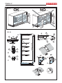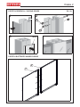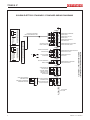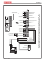
1
2030
324
70 H216
494
400
717
70 H203
65 H216
324
717
2160
667
444
350
667
65 H203
324
324
494
75 H216
767
544
450
767
75 H203
544
324
324
444
80 H216
817
594
500
817
80 H203
594
324
324
2030
2160
2030
2160
2030
2160
500
85 H216
867
644
500-550
867
85 H203
644
500-550
2030
2160
450
324
324
400
90 H216
917
694
500-600
917
90 H203
694
500-600
2030
2160
05060127 00 14/02/2012
324
324
350
Osaka 2
Rif. 1
1
Osaka 2
6
Rif. 2
10 8
1
ARNEG S.p.A.
VIA VENEZIA 58 - CAMPO SAN MARTINO - PADOVA - ITALY
Tel. +39 049 9699333 Fax +39 049 9699444 - [email protected]
2
3
5
9
11
12
14
CODICE
ITEM
16
COMMESSA
W.SCHED
V
SBRINAMENTO
DEFROSTING
SUPERF.ESP.
DISPLAY AREA
MATRICOLA
S/N
Hz
W
W IP
MASSA
WEIGHT
kg
13
m
2
REFRIGERANTE
REFRIGERANT
CLASSE
CLASS
ILLUSTRAZIONI
ILLUSTRATIONS
ABBILDUNGEN
ILLUSTRATIONS
ILLUSTRACIONES
ɂɅɅɘɋɌɊȺɐɂɂ
Rif.
ILLUMINAZIONE
LIGHTING
4
7
15
A
W
ORDINE
W.ORD.
17
ANNO
YEAR
18
Rif. 4
3
Rif. 7
Max 25mm
Rif. 6
Rif. 5
Rif. 8
2
Rif. 9
Rif.10
05060127 00 14/02/2012
Osaka 2
Rif.11
30 cm
Rif. 12
Rif. 13
160 kg/m
MAX 30°C
MAX 30 bar
2
0°
10°
passo montante 25mm
25mm upright pitch
Rif. 15
Rif. 14
Rif. 17
min 30mm
er
t
wa
CHEMICALS
Rif. 18
Rif. 16
2
1
L
A
N
10 mm
Prg
IO
T
P
aux
O
HACCP
mute
aux
Set
def
Rif. 21
Rif. 22
Rif. 19
05060127 00 14/02/2012
Rif. 20
3
Osaka 2
Rif. 23
1460
H2O
700
495
140
670
R404A
900
R404A
1250
900
175
480
1460
H2O
700
937.5
625
1250
900
480
R404A
1460
140
H2O
R404A
H2O
1250
900
TESTATE/HEAD CASES
140
1673
1506
495
86.5
86.5
H2O
1333
293
900
86.5
1500
86.5
460
140
900
140
R404A
770
595
1875
595
830
770
175
140
830
3750
670
900
H2O
2500
900
937.5
2710
140
1250
700
625
900
830
595
H2 O
835
770 - 820
870 - 920
R404A
R404A
1875
140
595
210
545
140
720
R404A
900
175
H2O
545
720
R404A
835
H2O
2500
1875
140
140
1250
937.5
625
900
830
175
495
175
480
770 - 820
870 - 920
545
720
175
670
H2O
210
770 - 820
870 - 920
595
835
140
595
495
670
175
R404A
2500
1875
1250
900
210
H2O
R404A
H2O
3750
900
R404A
140
H2O
566.5
753
566.5
836.5
1847
1674
86.5
634
900
R404A
H2O
86.5
140
830
1875
770
595
545
175
720
2710
3750
2710
900
140
R404A
H2O
595
595
770 - 820
870 - 920
566.5
923.5
830
1875
Rif. 24
4
05060127 00 14/02/2012
Osaka 2
Rif. 25
Sout
500
Sout
60
40
A
230
Sdef
Sdef
Part. A
Sin
70
70
Sin
Rif. 26
05060127 00 14/02/2012
70°
70° stand-by
70°
5
Osaka 2
Rif. 27
NO
ȅȀ
Rif. 28
A
A
1
120
A 25
B
3
C
6
4
3
5
5
25
B
60
3
6
2
10
9
8
7
1
2
1
MF
LF
C
5 C
A
5
A
05060127 00 14/02/2012
Osaka 2
PORTE SCORREVOLI / SLIDING DOORS
Rif. 29
2
1
9
10
3
INOX
PORTE A BATTENTE/ HINGED DOORS
2
7
05060127 00 14/02/2012
7
Osaka 2
SCHEMI ELETTRICI STANDARD / STANDARD WIRING DIAGRAMS
1 24 25 PE N 2A
1 24 25 PE N 2A
M
N
6
N
5
I
4
I
3
ALIMENTAZIONE ILLUMINAZIONE
LIGHTING SUPPLY
ALIMENTAZIONE CAVI CALDI
HEATERS SUPPLY
ALIMENTAZIONE TENDE NOTTE
NIGHT BLIND SUPPLY
ALIMENTAZIONE VENT. DOPPIA CORTINA
DOUBLE CURTAIN FANS SUPPLY
POWER 2
2
2
ALIMENTAZIONE VENTILATORI EVAPORATORE
EVAPORATOR FANS SUPPLY
PE 5A 5B
PE 5A 5B
ALIMENTAZIONE VALVOLA
VALVE SUPPLY
POWER 3
PE N R1
PE N R1
RESISTENZA SBRINAMENTO
DEFROST HEATER
ALIMENTAZIONE RESISTENZA SBRIN.
DEFROST HEATER SUPPLY
PROBES 1
3
4
4
5
5
6
6
Sin
3
SONDA RIPRESA ARIA
AIR INLET PROBE
2
Sdef
2
SONDA FINE SBRINAM.
END DEFROST PROBE
1
Sout
1
SONDA MANDATA ARIA
AIR OUTLET PROBE
PROBES 2
3
3
4
4
5
5
5
2
4
2
3
1
2
TRASDUTTORE DI PRESSIONE
PRESSURE TRANSDUCER
1
Sev
Ssh
S
SONDA INGRESSO REFRIGERANTE
REFRIGERANT INLET PROBE
SONDA SURRISCALDAMENTO
SUPERHEATING PROBE
+ -
Ssh
1
SONDA SURRISCALDAMENTO
SUPERHEATING PROBE
SCHEMA DI CABLAGGIO SENZA TERMOSTATI
WIRING DIAGRAM WITHOUT THERMOSTATS
PE N
+=ALIM./SUPPLY
-=COMUNE/COMMON
S=SEGNALE/SIGNAL
VALVOLA SOLENOIDE
SOLENOID VALVE
EEV
PE N
VENTILATORI EVAPORATORE
EVAPORATOR FANS
M
S
TRASDUTTORE RAZIOMETRICO
RATIOMETRIC TRANSDUCER
R
+ -
SCHEMA ILLUMINAZIONE VERTICALI TN: D5A15923
WIRING DIAGRAM OF LIGHTING FOR VERTICAL NT: D5A15923
+=ALIM./SUPPLY
S=SEGNALE/SIGNAL
VENT. DOPPIA CORTINA
DOUBLE CURTAIN FANS
PE N
2
CAVO/PROLUNGA PLAFONIERA
CANOPY CABLE/ADDITIONAL CABLE
PE N
1
S
mA
TRASDUTTORE DI PRESSIONE 4-20 mA
PRESSURE TRANSDUCER 4-20 mA
+
POWER 1
L
N
1
2
NON UTILIZZATI
NOT USED
5
6
8
05060127 00 14/02/2012
Osaka 2
Schemi elettrici
POWER 1
ALIMENTAZIONE ILLUMINAZIONE
LIGHTING SUPPLY
ALIMENTAZIONE CAVI CALDI
HEATERS SUPPLY
ALIMENTAZIONE TENDE NOTTE
NIGHT BLIND SUPPLY
ALIMENTAZIONE VENT. DOPPIA CORTINA
DOUBLE CURTAIN FANS SUPPLY
POWER 2
PE N
2
2
ALIMENTAZIONE VENTILATORI EVAPORATORE
EVAPORATOR FANS SUPPLY
PE 5A 5B
PE 5A 5B
M
VALVOLA SOLENOIDE
SOLENOID VALVE
EEV
PE N
PE
VENTILATORI EVAPORATORE
EVAPORATOR FANS
ALIMENTAZIONE VALVOLA
VALVE SUPPLY
PE N R1
PE N R1
RESISTENZA SBRINAMENTO
DEFROST HEATER
PE
S
ALIMENTAZIONE RESISTENZA SBRIN.
DEFROST HEATER SUPPLY
PROBES 1
3
4
4
5
5
6
6
Sin
3
Sdef
SONDA RIPRESA ARIA
AIR INLET PROBE
2
SONDA FINE SBRINAM.
END DEFROST PROBE
2
Sout
1
SONDA MANDATA ARIA
AIR OUTLET PROBE
1
+=ALIM./SUPPLY
-=COMUNE/COMMON
S=SEGNALE/SIGNAL
TRASDUTTORE RAZIOMETRICO
RATIOMETRIC TRANSDUCER
R
+ -
POWER 3
PROBES 2
2
3
3
4
4
5
5
5
2
4
1
3
1
2
3
L
4
N
1
1
CAVO TERM-TERMOSTATO
TERMOM.-THERMOSTAT CABLE
2
2
ALIMENTAZIONE
POWER SUPPLY
CONTATTO TERMOSTATO
THERMOSTAT CONTACT
5
5
6
6
7 6 5
TERMOSTATO FINE SBRINAMENTO
END DEFROST THERMOSTAT
CONTATTO TERMOSTATO
THERMOSTAT CONTACT
1 2 8
7 8
230VAC
L
N
CAREL IR****
1 2 3 4
ALIMENTAZIONE
POWER SUPPLY
3 4
1
2
3
4
5
6
DI
9 10 11 12
05060127 00 14/02/2012
TRASDUTTORE DI PRESSIONE
PRESSURE TRANSDUCER
Ssh
S
Sev
SONDA SURRISCALDAMENTO
SUPERHEATING PROBE
+ -
Ssh
SONDA INGRESSO REFRIGERANTE
REFRIGERANT INLET PROBE
1
SONDA SURRISCALDAMENTO
SUPERHEATING PROBE
SCHEMA DI CABLAGGIO CON TERMOSTATI E SONDE STANDARD (NTC 10K 25°C) SUL CONNETTORE PROBES 1
WIRING DIAGRAM WITH THERMOSTATS AND STANDARD PROBES (NTC 10K 25°C) ON PROBES 1 CONNECTOR
1 24 25 PE N 2A
M
1 24 25 PE N 2A
PE
N
6
N
5
I
4
I
3
PE N
2
+=ALIM./SUPPLY
S=SEGNALE/SIGNAL
SCHEMA ILLUMINAZIONE VERTICALI TN: D5A15923
WIRING DIAGRAM OF LIGHTING FOR VERTICAL NT: D5A15923
S
mA
TRASDUTTORE DI PRESSIONE 4-20 mA
PRESSURE TRANSDUCER 4-20 mA
+
VENT. DOPPIA CORTINA
DOUBLE CURTAIN FANS
PE N
1
CAVO/PROLUNGA PLAFONIERA
CANOPY CABLE/ADDITIONAL CABLE
9
Osaka 2
POWER 1
1 24 25 PE N 2A
M
1 24 25 PE N 2A
PE
N
6
N
5
I
4
I
3
PE N
2
ALIMENTAZIONE ILLUMINAZIONE
LIGHTING SUPPLY
ALIMENTAZIONE CAVI CALDI
HEATERS SUPPLY
ALIMENTAZIONE TENDE NOTTE
NIGHT BLIND SUPPLY
ALIMENTAZIONE VENT. DOPPIA CORTINA
DOUBLE CURTAIN FANS SUPPLY
PE N
2
2
ALIMENTAZIONE VENTILATORI EVAPORATORE
EVAPORATOR FANS SUPPLY
PE 5A 5B
PE 5A 5B
S
ALIMENTAZIONE VALVOLA
VALVE SUPPLY
POWER 3
PE N R1
PE N R1
RESISTENZA SBRINAMENTO
DEFROST HEATER
PE
ALIMENTAZIONE RESISTENZA SBRIN.
DEFROST HEATER SUPPLY
PROBES 1
4
4
5
5
6
6
Sin
3
SONDA RIPRESA ARIA
AIR INLET PROBE
3
Sdef
2
SONDA FINE SBRINAM.
END DEFROST PROBE
2
Sout
1
SONDA MANDATA ARIA
AIR OUTLET PROBE
1
+=ALIM./SUPPLY
-=COMUNE/COMMON
S=SEGNALE/SIGNAL
TRASDUTTORE RAZIOMETRICO
RATIOMETRIC TRANSDUCER
R
+ -
VALVOLA SOLENOIDE
SOLENOID VALVE
EEV
PE N
M
VENTILATORI EVAPORATORE
EVAPORATOR FANS
PROBES 2
2
3
3
4
4
5
5
5
2
4
1
3
1
2
TRASDUTTORE DI PRESSIONE
PRESSURE TRANSDUCER
Ssh
S
Sev
SONDA SURRISCALDAMENTO
SUPERHEATING PROBE
+ -
Ssh
SONDA INGRESSO REFRIGERANTE
REFRIGERANT INLET PROBE
1
SONDA SURRISCALDAMENTO
SUPERHEATING PROBE
3
L
4
N
ALIMENTAZIONE
POWER SUPPLY
1
1
CAVO TERM-TERMOSTATO
TERMOM.-THERMOSTAT CABLE
2
2
CONTATTO TERMOSTATO
THERMOSTAT CONTACT
5
5
6
6
SONDA MANDATA ARIA NTC
AIR OUTLET PROBE NTC
Sout1
1
2
3
4
5
6
DI
9 10 11 12
TERMOSTATO FINE SBRINAMENTO
END DEFROST THERMOSTAT
Sdef2
7 6 5
CAREL IR****
7 8
230VAC
L
N
SONDA FINE SBRINAM. NTC
END DEFROST PROBE NTC
1 2 8
1 2 3 4
10
CONTATTO TERMOSTATO
THERMOSTAT CONTACT
3 4
ALIMENTAZIONE
POWER SUPPLY
SCHEMA DI CABLAGGIO CON TERMOSTATI E SONDE NON STANDARD SUL CONNETTORE PROBES 1
WIRING DIAGRAM WITH THERMOSTATS AND NOT STANDARD PROBES ON PROBES 1 CONNECTOR
POWER 2
PE
+=ALIM./SUPPLY
S=SEGNALE/SIGNAL
SCHEMA ILLUMINAZIONE VERTICALI TN: D5A15923
WIRING DIAGRAM OF LIGHTING FOR VERTICAL NT: D5A15923
S
mA
TRASDUTTORE DI PRESSIONE 4-20 mA
PRESSURE TRANSDUCER 4-20 mA
+
VENT. DOPPIA CORTINA
DOUBLE CURTAIN FANS
PE N
1
CAVO/PROLUNGA PLAFONIERA
CANOPY CABLE/ADDITIONAL CABLE
05060127 00 14/02/2012
05060127 00 14/02/2012
db (A)
bar
1162 1549 2323
6,9
7,83
1224 1631 2447
3,92
881
2,61
5,22
7,83
1321 1762 2642
3,92
29 bar (CO2-60 bar)
R404A (optional R 134a, R410A, CO2, Glicole)
816
2,61
914
2,92
5,85
< 65
db (A)
bar
3,3
4,95
6,6
9,9
3,36 5,04 6,72 10,08 3,36 5,04 6,72 10,08
< 65
Naturale, Off-cycle, Zeitabtauung, Dégivrage naturel, Parada simple, ɉɪɨɫɬɚɹɨɫɬɚɧɨɜɤɚ
29 bar (CO2-60 bar)
R404A (optional R 134a, R410A, CO2, Glicole)
9,9
1012 1518 2024 3037 1094 1640 2187 3281 1029 1543 2058 3087 1110 1665 2221 3331 1046 1568 2091 3137 1127 1691 2254 3381
6,6
dm 3
4,95
3,24 4,85 6,47 9,71 3,24 4,85 6,47 9,71
m2
3,3
Max + 32°C / Min - 10°C
90/216
°C
90/200
0°C/+2°C +2°C /+4°C
85/216
8,77
°C
85/200
5,85
1250 1875 2500 3750 1250 1875 2500 3750 1250 1875 2500 3750 1250 1875 2500 3750 1250 1875 2500 3750 1250 1875 2500 3750
80/216
4,39
987 1481 1974 2962
2,92
mm
80/200
Contenuto modificabile senza preavviso, Content that could be change without notice, Inhalt Veränderbar ohne Vorankündigung, Contenu modifiable sans préavis, Contenido modificable sin previo aviso, ɋɨɞɟɪɠɚɧɢɟɢɡɦɟɧɹɟɬɫɹɛɟɡɩɪɟɞɭɩɪɟɠɞɟɧɢɹ
Massima pressione ammissibile, Max allowed pressure, Maximal zulässiger
Druck, Pression maximale admissible, Máxima presión admitida, Ɇɚɤɫɢɦɚɥɶɧɨ
ɞɨɩɭɫɬɢɦɨɟ Ⱦɚɜɥɟɧɢɟ- (Ps) 97/23 CE Tipo di sbrinamento, Defrosting type, Abtautyp, Type de dégivrage, Tipo
descongelation, Ɍɢɩɨɬɬɚɢɜɚɧɢɹ
Livello di rumorosità , Noise level, Schallpegel, Niveau de bruit, Nivel de ruido,
ɍɪɨɜɟɧɶɲɭɦɚ
Refrigerante, Refrigerant, Kühlmittel, Réfrigérant, Refrigerante, ɏɥɚɞɚɝɟɧɬ
Lunghezza senza spalle, Length without ends, Länge ohne Seiten,
Longeur sans joues, Longitud sin laterales, Ⱦɥɢɧɚɛɟɡɛɨɤɨɜɢɧ
Temp. di esercizio, Working temperature, Betriebstemperatur,
Temp. de fonctionnement, Temperatura de trabajo, Ɋɚɛɨɱɚɹɬɟɦɩɟɪɚɬɭɪɚ
Temperature ammissibili, Allowed temperature, Zulässige Temperaturen
Températures admissibles, Temperaturas admitidas, Ⱦɨɩɭɫɬɢɦɵɟɬɟɦɩɟɪɚɬɭɪɵ
- (Ts) 97/23 CE Superficie di esposizione orizzontale, Horizontal display surface, Gesamte
Ausstellefläche, Surface d ’exposition horizontale , Superficie de exposición de
apoyo, Ƚɨɪɢɡɨɧɬɚɥɶɧɚɹɩɥɨɳɚɞɶɷɤɫɩɨɡɢɰɢɢ
Volume netto, Net volume, Netto inhalt, Volume net, Volumen neto,
ɑɢɫɬɵɣɜɟɫ
Modello, Model, Modell, Modele, Modelo, Ɇɨɞɟɥɶ
8,77
1371 1828 2742
4,39
Naturale, Off-cycle, Zeitabtauung, Dégivrage naturel, Parada simple, ɉɪɨɫɬɚɹɨɫɬɚɧɨɜɤɚ
774
4,6
Contenuto modificabile senza preavviso, Content that could be change without notice, Inhalt Veränderbar ohne Vorankündigung, Contenu modifiable sans préavis, Contenido modificable sin previo aviso, ɋɨɞɟɪɠɚɧɢɟɢɡɦɟɧɹɟɬɫɹɛɟɡɩɪɟɞɭɩɪɟɠɞɟɧɢɹ
Massima pressione ammissibile, Max allowed pressure, Maximal zulässiger
Druck, Pression maximale admissible, Máxima presión admitida, Ɇɚɤɫɢɦɚɥɶɧɨ
ɞɨɩɭɫɬɢɦɨɟ Ⱦɚɜɥɟɧɢɟ- (Ps) 97/23 CE Tipo di sbrinamento, Defrosting type, Abtautyp, Type de dégivrage, Tipo
descongelation, Ɍɢɩɨɬɬɚɢɜɚɧɢɹ
Livello di rumorosità , Noise level, Schallpegel, Niveau de bruit, Nivel de ruido,
ɍɪɨɜɟɧɶɲɭɦɚ
1076 1435 2152
3,45
717
2,3
dm 3
6,9
5,22
4,6
2,3
m2
3,45
Max + 32°C / Min - 10°C
75/216
°C
75/200
0°C/+2°C +2°C /+4°C
. Datos Técnicos
Refrigerante, Refrigerant, Kühlmittel, Réfrigérant, Refrigerante, ɏɥɚɞɚɝɟɧɬ
. Òåõíè÷åñêèå õàðàêòåðèñòèêè
70/216
. Données techniques
°C
70/200
. Technische Daten
1250 1875 2500 3750 1250 1875 2500 3750 1250 1875 2500 3750 1250 1875 2500 3750 1250 1875 2500 3750 1250 1875 2500 3750
65/216
. Technical data
mm
65/200
. Dati tecnici
Lunghezza senza spalle, Length without ends, Länge ohne Seiten,
Longeur sans joues, Longitud sin laterales, Ⱦɥɢɧɚɛɟɡɛɨɤɨɜɢɧ
Temp. di esercizio, Working temperature, Betriebstemperatur,
Temp. de fonctionnement, Temperatura de trabajo, Ɋɚɛɨɱɚɹɬɟɦɩɟɪɚɬɭɪɚ
Temperature ammissibili, Allowed temperature, Zulässige Temperaturen
Températures admissibles, Temperaturas admitidas, Ⱦɨɩɭɫɬɢɦɵɟɬɟɦɩɟɪɚɬɭɪɵ
- (Ts) 97/23 CE Superficie di esposizione orizzontale, Horizontal display surface, Gesamte
Ausstellefläche, Surface d ’exposition horizontale , Superficie de exposición de
apoyo, Ƚɨɪɢɡɨɧɬɚɥɶɧɚɹɩɥɨɳɚɞɶɷɤɫɩɨɡɢɰɢɢ
Volume netto, Net volume, Netto inhalt, Volume net, Volumen neto,
ɑɢɫɬɵɣɜɟɫ
Modello, Model, Modell, Modele, Modelo, Ɇɨɞɟɥɶ
Osaka 2
Dati Tecnici, Technical Data, Technische Daten, Données techniques, Datos Técnicos, Ɍɟɯɧɢɱɟɫɤɢɟ ɯɚɪɚɤɬɟɪɢɫɬɢɤɢ
11
Osaka 2
English
Installation and User Manual
CONTENTS
ILLUSTRATIONS.................................................................................................................
Technical data......................................................................................................................
1 - Informational symbols.....................................................................................................
2 - Prohibitions and prescriptions.........................................................................................
3 - Purpose of the Manual/Field of Application - Interested Parties.....................................
4 - Presentation - Proper use (Rif. 1) ...................................................................................
5 - Standards and certifications ...........................................................................................
6 - Identification - Plate data (Rif. 2) ....................................................................................
7 - Transport - specialised technician - ................................................................................
8 - Storage ...........................................................................................................................
9 - Receipt, unpacking, initial cleaning - qualified operator - ...............................................
10 - Installation and environmental conditions - specialised technician - ............................
11 - Multiplexing cabinets - specialised technician - ............................................................
12 - Electrical connection - specialised technician - ............................................................
13 - Probe placement - specialised technician - ..................................................................
14 - Start-up, temperature control and adjustment - specialised technician -......................
15 - Filling the unit - qualified operator - ..............................................................................
16 - Defrosting and water discharge (Rif. 23) ......................................................................
16_1 - Water discharge: ..................................................................................................
17 - Lighting .........................................................................................................................
18 - Replacing bulbs (Rif. 18) ..............................................................................................
19 - Glass doors...................................................................................................................
20 - Maintenance and cleaning - qualified operator -...........................................................
20_1 - General instructions .............................................................................................
20_2 - Cleaning of external parts (Daily/Weekly) ............................................................
20_3 - Cleaning of internal parts (Monthly) .....................................................................
20_4 - Cleaning the "honeycomb" (Rif. 7) .......................................................................
20_5 - Cleaning glass parts.............................................................................................
20_6 - Cleaning stainless steel parts ..............................................................................
20_7 - Cleaning aluminium parts.....................................................................................
20_8 - Parts inspection....................................................................................................
21 - Dismantling the unit - specialised technician -..............................................................
05060127 00 14/02/2012
2
11
26
26
27
28
28
29
29
30
30
30
31
31
32
32
32
33
33
33
33
34
34
35
35
35
35
36
36
36
36
36
25
Osaka 2
English
1. Informational symbols
Before reading the manual, take a moment to learn the symbols:
This symbol indicates dangers and actions that should always be avoided during
use, maintenance or in any situation, as they could cause serious injury or death.
This symbol indicates instructions, rules, advice, and communications that each
person assigned to use the unit (in reference to their individual responsibilities)
must respect during the entire time they are using the unit (installation, use,
maintenance, dismantling, etc.).
2. Prohibitions and prescriptions
The Installation and User Manual should be read carefully so that the operator, in the
event of malfunction, is able to provide precise information to Technical Support.
zBefore carrying out any maintenance work on the refrigerator unit,
please ensure that the electrical supply is disconnected.
zThese units are designed for use only in closed environments
zTake great care over all working manoeuvres (loading, unloading,
cleaning, counter service, maintenance, etc.). and always apply
maximum diligence, using appropriate protective equipment for the
various operations.
zThe refrigeration unit is intended to maintain the temperature of the
goods displayed and not to reduce it. Foodstuffs should only be placed
inside if they are already cooled to their respective conservation
temperatures. As such, products that have been warmed up must not be
placed in the unit.
zThe units are designed and built to store and display only fresh and
frozen foods, ice creams, cooked and pre-cooked items (canteens). Do
not introduce any type of goods other than those specified such as
pharmaceutical products, fishing bait, etc.
zCheck that the temperature and relative humidity values do not exceed
specifications. For this reason it is essential that the air-conditioning,
ventilation, and heating systems in the sales point are kept at maximum
efficiency.
zLimit the speed of the ambient air near the unit openings to less than 0.2 m/s;
zAvoid having air currents or the output of the air conditioning system aimed
directly towards unit openings.
zOnly place goods into the cabinet that have already been cooled to the
temperature normally applicable to the cold chain and check that the cabinet
is always able to maintain that temperature.
zRespect the load limit. Do not overload the cabinet.
zRotate food products by loading the cabinet in such a way that the goods
displayed for longest are sold before new arrivals.
zWith the help of a specialised technician, eliminate any problems found (loose
screws, blown bulbs, etc.).
zCheck the flow of defrosted water (unblock drains, clean any filters, check
siphons, etc.).
zDispose of defrosted water or water used for washing through the drains or
purification system in accordance with current legislation as this may come
into contact with pollutants due to the nature of the product, any residues,
accidental breakages of casing containing liquids and the use of nonpermitted detergents.
zIf abnormal condensation forms, inform the refrigeration technician
immediately.
zCarry out all preventive maintenance operations punctually.
26
05060127 00 14/02/2012
Osaka 2
English
zDO NOT use the unit barefoot
zDO NOT touch the unit with wet or damp hands or feet
zDO NOT remove protective covers or panels that require
the use of tools to be
removed. More specifically, do not remove the electrical panel cover. These
operations must always be carried out by specialised technicians.
zDO NOT obstruct the air intake openings.
zDO NOT walk on the top of the unit.
zDO NOT use your feet to climb onto the front of the unit, for any reason. If
necessary, use an appropriate and suitable ladder in order to reach the
loading points. Danger: falls and serious injury.
zDO NOT use spotlights with incandescent bulbs aimed directly at the unit.
Danger: overheating the merchandise.
zExposed merchandise should not be in direct sunlight. Danger: alteration of
merchandise.
zLimit the temperature of radiating surfaces located in the sales point, e.g.
insulating ceilings.
zIN THE CASE OF A GAS LEAK OR FIRE:
Do not stay in the room where the cabinet is located if it is not appropriately ventilated. Disconnect the unit by means of the general switch
upstream of the appliance.
DO NOT USE WATER TO PUT OUT THE FLAMES, USE ONLY DRY
EXTINGUISHERS.
ANY OTHER USE NOT EXPLICITLY INDICATED IN THIS MANUAL IS TO BE
CONSIDERED DANGEROUS. THE MANUFACTURER SHALL NOT BE HELD
RESPONSIBLE FOR ANY DAMAGES THAT MAY OCCUR FROM IMPROPER,
ERRONEOUS, OR UNREASONABLE USE.
USEFUL TELEPHONE NUMBERS:
SWITCHBOARD +39 0499699333 - FAX +39 9699444 - CALL CENTRE 848 800225
3. Purpose of the Manual/Field of Application - Interested Parties
This instruction manual contains a description of the Osaka 2 line of refrigeration units,
manufactured by ARNEG Spa.
The following information provides instructions with regard to:
zusing the cabinet
ztechnical specifications
zinstallation and assembly
zoperator information
zmaintenance operations
zsafety information
The manual should be considered part of the unit and must be kept for its entire
working life.
The manufacturer is relieved from all liability in the following situations:
zimproper use
zincorrect installation - not completed in accordance with the regulations specified
zpower supply faults
zserious lack of maintenance
zunauthorised alterations and operations
zuse of non-original spare parts
zpartial or complete lack of compliance with the instructions.
This manual must be the responsibility of an assigned person, stored in an appropriate
location, known to all assigned workers and maintenance employees, so that it can be
consulted whenever needed.
In the event of transfer to third parties, it must be delivered to the new user or owner,
duly informing the suppliers in a timely manner. If lost or damaged, please contact the
supplier.
This manual is intended for:
05060127 00 14/02/2012
27
Osaka 2
English
QUALIFIED OPERATORS: qualified individuals, instructed in the use, adjustment,
cleaning, and maintenance of the unit.
SPECIALISED TECHNICIANS: trained technicians, authorised to carry out
extraordinary maintenance, repair, replacement, and tuning operations who are aware
of the risks they are exposed to in carrying out said operations and able to adopt all the
measures appropriate to protect themselves and others, minimising damage with
respect to the risks that these operators have.
Where not specified, the section is applicable to both types of users
The contents of this manual represent the current technical and technological status
used in manufacturing the unit, and valid at the time the unit in question was sold.
Therefore, it cannot be considered obsolete in the case of later updates connected to
new regulations or knowledge. Anyone using this unit must read this manual.
4. Presentation - Proper use (Rif. 1)
The unit is intended for use by qualified personnel that have been instructed and
trained by their employer with regards to use and the risks that come with it.
The Osaka 2 refrigeration unit line designed for foodstuffs consists of vertical
wall display units closed at the front with wing doors, with remote condenser
unit, perfect for the storage and sale of salamis, dairy produce, ready-prepared
fruits and vegetables, and meat.
zElectrical appliances can be dangerous to health. Current laws and
regulations must be respected during installation and use.
zRemoving protective covers or panels requiring tools for removal is prohibited.
DO NOT allow the following types of people to use the unit:
zchildren
zpersons who cannot safely use the unit without supervision or instructions
zdisabled individuals
zemployees who are not sober or are under the effect of narcotics
zCarefully read the manual before use and instruct assigned employees with
regards to the various operations (transport, installation, maintenance, etc.),
in line with their assigned responsibilities, and in accordance with the
instructions contained in the manual.
zThe Client or employer assumes full responsibility regarding the qualification
and mental and/or physical state of the employees assigned to use and
maintain the unit.
zThis documentation CANNOT in any way serve as a substitute for a lack of
education or intelligence in the personnel that interacts with the equipment.
zThe units are designed and built to store and display only fresh and frozen
foods, ice creams, cooked and pre-cooked items (canteens). Do not introduce
any type of goods other than those specified such as pharmaceutical products, fishing bait, etc.
5. Standards and certifications
All the refrigeration unit models described in the user manual for the Osaka 2 series
meet the essential requirements for safety, health, and protection, as required by the
following European directives and laws:
zMachines Directive 2006/42 EC;
applied EN norms: EN ISO 14121:2007; EN ISO 12100-1:2005; EN ISO 121002:2003
zElectromagnetic Compatibility Directive 2004/108/EC;
applied EN norms: EN 61000-3-2:2006; EN 61000-3-12:2005; EN 55014-1:2006; EN
55014-2:1997;
zLow Voltage Directive 2006/95/EC;
applied EN norms: EN 60335-1:2008; EN 60335-2-89 :2002/A2:2007
European Regulation EC-1935/2004 on materials and articles intended to come into
contact with food - standards applied: EN 1672-2
28
05060127 00 14/02/2012
Osaka 2
English
They are excluded from the field of application of Directive EEC 97/23 (PED) on the
basis of that specified by Article 3 paragraph 3 of the Directive.
In the case that the original copy of the Declaration of Product Conformity provided with the product is lost, it is possible to download a copy by completing the
form found at the following website: http://www.arneg.it/conformity
The performance of these refrigeration units has been determined using tests carried
out in accordance with UNI EN ISO 23953-2: 2006 regulations, in the environmental
conditions corresponding to climate class 3 (25 °C , 60% R.H.)
Environmental climatic classes according to UNI EN ISO 23953 - 2
Climatic class
1
2
3
4
5
6
Temp. dry bulb
16°C
22°C
25°C
30°C
40°C
27°C
Relative humidity
80%
65%
60%
55%
40%
70%
Dew point
12°C
15°C
17°C
20°C
24°C
21°C
6. Identification - Plate data (Rif. 2)
A serial plate is affixed behind the unit, stating all characteristic data:
1) Manufacturer's name and address
2) Unit name and length
3) Unit code
4) Unit serial number
5) Voltage supply
6) Supply frequency
7) Current used when operating
8) Electrical power used when operating during refrigeration phase (fans+hot
cables+lighting)
9) Electrical power used when operating during defrost phase (armoured
resistances+hot cables+fans+lighting)
10) Lighting power (where applicable)
11) Net display surface
12) Type of refrigerant fluid with which the system functions
13) Mass of refrigerant gas with which each system has been loaded (only for units
with built-in motor)
14) Environmental climatic class and temperature of reference
15) Humidity protection class
16) Unit manufacturing order number
17) Unit production order number
18) Unit year of production
In the case of a request for technical assistance, please provide the following information:product name (Rif. 2 - 2); serial number (Rif. 2 - 4); work order number (Rif. 2 - 16).
7. Transport - specialised technician Loading/unloading operations must always be carried out by qualified personnel able
to check weights, exact lifting points, and the most appropriate means of transport,
both in terms of safety and capacity. The cabinets are supplied on a wooden platform
frame to the base for movement with forklift trucks. Use a manual or electrical forklift
truck that is suitable for moving the cabinet in question. It must have a nominal capacity
of at least 1,000 kg.
zAlways place the forks at the indicated points in order to avoid the risk of
overturning, and always completely insert the forks.
zNo unnecessary personnel should be present in the lifting area.
zBalance the weight of the unit so as to ensure that the load remains in equilibrium (Rif. 3)
05060127 00 14/02/2012
29
Osaka 2
English
DO NOT use transportation devices to lift:
zwith a capacity of less than 1,000 kg
zwith inappropriate characteristics or that have been affected by use
zwith non-standard or worn wires or cables
Transportation procedures that differ from that indicated are prohibited.
8. Storage
zDO
NOT store the units in uncovered areas where they are subject to weathering
and direct sunlight. Exposure to ultraviolet rays leads to permanent deformation of
the plastic materials and damages the unit’s components.
zThe units must be stored in closed areas, at a temperature between -25°C and
+55°C and with relative humidity between 30% and 90%.
zBefore storing, check that the packaging is intact and that it doesn't show any
defects that could compromise the preservation of the units.
9. Receipt, unpacking, initial cleaning - qualified operator Before starting any unpacking operations, take all possible precautions to avoid injury
to the operator.
The unit may be provided packaged in one of the following ways:
zWith a wooden frame fixed to the base and a nylon covering held in place by straps
(standard) (Rif. 8);
zWith cardboard covering (upon request) (Rif. 9);
zWith a wooden cage (upon request) (Rif. 10).
Upon acceptance of the cabinet:
zEnsure that the packaging is intact and there is no obvious damage;
zUnpack, ensuring that the unit is not damaged;
zCheck that all parts of the unit are intact;
zIf any damage is found, immediately contact your supplier;
zSlowly remove the protective film, taking care to not rip it, in order to avoid leaving
traces of glue. If this occurs anyway, they can be removed using appropriate
solvents.
zClean for the first time using neutral products. Dry with a soft cloth. Do not use any
abrasive substances or metal sponges;
For correct disposal of the packaging, note that it consists of: Wood - Polystyrene - Polythene - PVC - Cardboard.
zDO NOT use alcohol to clean the methacrylate parts (Plexiglas).
zDuring the unpacking operations, do not leave packaging elements such as
nails, wood, staples, nylon, etc. lying around and tools used for the operation
such as pliers, scissors, and pincers should not be left in the work area, as
they could cause injury or wounds.
zThese items should be removed using appropriate methods and placed in the
relevant waste collection locations.
10.Installation and environmental conditions - specialised technician Any change to the installation described here must be authorised by ARNEG
Spa.
To guarantee that the technicians assigned to install the unit work safely, the use of
protective tools and clothing required under the safety regulations or laws in effect in
the country where it is installed is recommended. In any case, always use appropriate
equipment and clothing, such as: safety shoes, protective gloves, a level.
For installation, please proceed as follows:
zcarefully inspect the installation area, removing any danger(s) to the operator:
Do not position the cabinet:
zin environments with the presence of explosive gaseous substances;
30
05060127 00 14/02/2012
Osaka 2
English
zoutdoors
and therefore where there are atmospheric agents;
znear heat sources (in direct sunlight, near heating systems, incandescent lights,
etc.)
znear air currents (near doors, windows, air-conditioning/heating systems, etc.)
exceeding speeds of 0.2 m/sec.
Remove the wooden supports on the bottom (used for transportation) and attach the
adjustable feet (Rif. 5) positioning them so that the unit is horizontal, using a level (Rif.
6) to check the alignment.
Before connecting the unit to the electricity, ensure that the plate data corresponds to
the characteristics of the electrical system to which it is to be connected.
For the unit to function properly, the temperature and relative humidity must not exceed
the limits for climate class 3 (+25°C; R.H. 60%) as established in EN-ISO 23953 - 2 regulations, under which the unit was tested.
zMultiplex up to 3 cabinets on the same electrical and refrigeration
supply line (1 master + 2 slaves)
zThe unit must be assembled with an inclination towards the wall of at
least 10mm (Rif. 20)
zIf the unit is moved, repeat the levelling process, as improper levelling
could compromise the unit's operations.
zThe unit must be levelled both in the front and in the back.
11.Multiplexing cabinets - specialised technician zBefore
multiplexing, make sure that the units are level and that doors
and handles are perfectly aligned.
To multiplex two or more units, proceed as follows:
zDisassemble the sides (if present).
zPosition the cabinets side by side
zRemove the back panels to gain access to the rise holes
zJoin the rises and brackets using the screws supplied
zReplace the back panels.
zCheck that the aligning plugs are inserted in the appropriate housings.
zSliding doors (Rif. 29): after completing multiplexing of the frames, apply the
provided stainless steel plate between the frames, in the internal part of the unit.
12.Electrical connection - specialised technician BEFORE STARTING ANY OPERATION, FIRST DISCONNECT THE SYSTEM FROM
THE POWER SUPPLY! The electrical system must be earthed!
zThe
systems must be completed in accordance with the regulations that
govern construction, installation, use, and maintenance as envisaged under
the norms in effect in the country where the unit is installed.
zARNEG Spa declines any responsibility with regards to the user and thirdparties for damages caused by breakdowns or malfunctioning of the systems
installed upstream to the unit and for damages caused by the same due to
causes directly attributable to malfunctioning of the electrical system.
zThe unit must be protected upstream by an automatic omnipolar thermomagnetic switch with appropriate characteristics. This must also act as a general
line disconnection switch.
Establishment of the electrical power supply line to the point of where it connects to the
unit is the responsibility of the Client. The dimensions of the electrical energy power
supply line must be determined in accordance with the electrical power used by the
unit (see Technical Specifications).
zRemove any metal objects worn: rings, watches, bracelets, earrings, etc.
zCheck the electrical diagrams before carrying out the connection
zCheck that the voltage supply is as specified on the plate data.
05060127 00 14/02/2012
31
Osaka 2
English
zTell
the operator where the switch is so that it can be reached quickly in an
EMERGENCY.
zTo guarantee correct operation, the maximum voltage variation must be between +/
- 6% of the nominal value.
zCheck that the power line has appropriate section cables, is protected against
overcurrent and dispersions towards earth, in compliance with current standards.
zIn the event of an interruption to the electricity supply, check that all store electrical
appliances can reboot without causing the overload protections to intervene. If not,
alter the system in order to differentiate between the start-up of the various
devices.
The installer must supply the anchorage devices for all cables in and out of the unit.
zAvoid having the casing come into contact with the electrical panel to avoid
electric shocks which could cause injury or death.
zCheck that the connectors of the illumination (shelves, ceiling, superstructure)
are inserted properly and blocked in their sockets so as to avoid disconnection during cleaning and maintenance operations which could lead to electrical shocks harmful to the operator.
The automatic thermomagnetic switch should be designed so as not to open the neutral circuit without simultaneously opening the phases. In any case, the opening distance for the contacts must be at least 3mm.
13.Probe placement - specialised technician The probes are already placed on the unit and are as follows:
Sout Air delivery control probe
Sdef End defrost thermostat control probe
Sin Air intake control probe
zTemperature probe: NTC IP67 L=4000 code 04510153.
zThe Sout-Sin probes must be fixed in place using terminals and should not be
insulated.
zThe Sdef probe must be fixed in place in contact with the fins of the evaporator,
between the 3rd and 4th tube (never in correspondence with the fan) using the
stainless steel bulb block spring, code 02230021.
14. Start-up, temperature control and adjustment
- specialised technician The refrigeration temperature is controlled using the mechanical thermometer (Rif. 22)
or with the electronic control device (OPTIONAL) (Rif. 21).
Normally the controller is set in the factory during testing, but it is possible to alter the
programming. To do so, please refer to the instructions given by the control device
manufacturer.
15.Filling the unit - qualified operator To refill the unit, you must comply with some important rules:
zload the cabinet one door at a time;
zblock the door open until loading is complete, avoiding continually opening and
closing;
zarrange the goods in a uniform, orderly fashion, avoiding overloading the shelves
(max. load 160 kg/m2) (Rif. 14).
zthe arrangement of goods, without leaving empty areas, guarantees optimum unit
function.
zleave approx. 30 mm of space between the merchandise and the shelf above (Rif.
16).
zarrange the goods in a way that does not interfere with the circulation of the
refrigerated air (Rif. 19)
zshelves can be placed in 2 positions 0°; -10°(Rif. 14), upon request it is possible to
32
05060127 00 14/02/2012
Osaka 2
English
add a third position at -20°.
zThe refrigeration unit is designed to maintain the temperature of the product
displayed and not to lower it. Food products must only be introduced if already
cooled to their respective storage temperatures.
zDO NOT introduce products that have been heated.
zDO NOT load the top of the unit with boxes, packages, or other things (Rif.
17).
zDO NOT climb on the front of the unit to ease loading operations, for any
reason (Rif. 13). Use an appropriate and suitable ladder to reach the loading
points. It is the Client's responsibility to ensure that all operations are carried
out safely and in accordance with the norms in effect
zDO NOT obstruct the refrigerated air entry in an way (merchandise, price
labels, price holders, etc.)
maximum allowable load for the shelves is 160kg/m2 and for the tank is
350kg/m2
zDO NOT load the cabinet with all doors open at the same time (Rif. 27);
zLimit the time the doors are open during loading of merchandise.
zIt is the responsibility of the client to use appropriate communication methods
to inform customers how the doors work and not to climb on the front to reach
products.
zTo avoid merchandise sliding on tilted shelves, always use the containment
edges.
zFirst use up the goods that have been stored in the unit the longest, before
adding new arrivals (food stock rotation);
zThe
16.Defrosting and water discharge (Rif. 23)
The Osaka 2 line of refrigeration units is provided with a simple-stop system by
means of the stopping of the refrigeration cycle.
Electric defrosting can be requested as an option (defrosting occurs by stopping the
refrigeration cycle and the use of an armoured resistance in the evaporator).
16_1.Water discharge:
To drain the defrost water, you need to:
zhave a floor drain with a slight incline (Rif. 24);
zinstall the provided siphon between the unit drainage pipe and the floor connection.
zhermetically seal the floor drainage area.
This will prevent unpleasant odours from forming within the unit, the dispersion of
refrigerated air and possible unit malfunctioning due to humidity.
Periodically check that the hydraulic connections are still efficient, contacting a
qualified installer.
17.Lighting
Internal lighting of the unit is obtained by OSRAM fluorescent lights. The light switch is
beside the light fixture.
For greater energy savings, the cabinet can be ordered complete with low
consumption LED lighting. This allows for:
zreduced lighting consumption
zreduced refrigerator load
zlifespan of lights: over 6 years
zuniform light intensity and colour
zimproved lighting as temperature decreases.
18.Replacing bulbs (Rif. 18)
Replace the bulbs as follows:
zTurn off the unit's power supply.
05060127 00 14/02/2012
33
Osaka 2
English
zUnhook the light fixture from the shelf.
zRemove the methacrylate guard (1), slide
out the bulb (2) from the housing, and
replace it with the new one.
zReinsert the light, making sure that the contacts are correctly placed in the
appropriate openings.
zReattach the methacrylate guard.
zHook the light fixture back onto the shelf.
zRestore the electricity supply.
19.Glass doors
The unit has front wing doors in low heat-dispersion glass.
Sliding doors are available on request.
The doors in low heat-dispersion glass allow for a noticeable reduction in refrigeration
energy, ensuring improved temperature level of foodstuffs and guaranteeing conservation quality.
(Rif. 26) The doors are provided with automatic closure and close automatically
starting from an angle of approx. 70°.
Beyond 70° the doors will be in stand-by -- essentially they remain in place in
order to allow for loading or cleaning operations. To unblock them and close the
doors, simply accompany them to the closed position.
zIn case of difficulty in opening or closing, DO NOT force them but try to find
the cause of the malfunction.
zAvoid actions not envisaged for the closing and movement system.
20.Maintenance and cleaning - qualified operator BEFORE CARRYING OUT ANY MAINTENANCE WORK OR
CLEANING, FIRST DISCONNECT THE UNIT FROM THE VOLTAGE
SUPPLY BY MEANS OF THE GENERAL SWITCH. ALWAYS WEAR
z
PROTECTIVE GLOVES FOR CLEANING.
Food products can deteriorate due to microbes and bacteria. Respecting hygiene
norms is essential in order to guarantee protection of consumer health, as well as
respecting the chain of refrigeration, for which the sales point is the last controllable
ring.
Cleaning operations must include:
1 - WASHING (removing grease, removal of about 97% of the dirt)
2 - DISINFECTING (using appropriate detergents on the surfaces to remove any
pathogenic micro-organisms that might remain after washing).
3 - RINSING
4 - DRYING
Cleaning the refrigeration units is carried out as follows:
34
05060127 00 14/02/2012
Osaka 2
English
20_1.General instructions
zThe surfaces to be cleaned and the detergents and water used for
cleaning must not exceed a maximum temperature of 30°C.
zuse only neutral type detergents
zDO NOT use acid or alkaline detergents (e.g. bleach) which could corrode the
surface
zDO NOT use abrasive products, chemical/organic solvents, or pointed tools
that could damage the unit's surfaces.
zDO NOT use detergents with unknown chemical compositions
zDO NOT spray water or detergent directly onto the electrical parts of the unit
and avoid wetting fans, light fixtures, electrical cables, and all electrical
equipment in general during cleaning operations.
zDO NOT touch the unit with wet or damp hands or feet
zDO NOT use alcohol or similar products to clean the methacrylate parts
(plexiglass).
zDO NOT aim the jet directly at painted or plastic-coated surfaces
zDO NOT apply the products directly onto the surfaces to be cleaned
zDO NOT use steam cleaning equipment
zDO NOT use excessive force during cleaning operations
zavoid contact with or inhaling vapours emitted from acid, alkaline or ammonia
products contained in flooring detergents which may oxidise or corrode
stainless steel.
zif internal cleaning is done with water jet cleaners (Rif. 11), use a LOW
PRESSURE system (max 30 bar) with an appropriate capacity to remove any
residue present. Excessive pressure could damage the surfaces.
zkeep a minimum distance of 30 cm from the surfaces being cleaned (Rif. 11).
zDO NOT bring the jet too close to the dirt, it can cause injury to the operator
and contaminate parts that have already been cleaned, as well as the
environment (Rif. 12).
20_2.Cleaning of external parts (Daily/Weekly)
zOn a weekly basis, clean all the external parts of the unit using neutral detergents
for domestic use that are compatible with the surfaces to be cleaned, or use warm
soapy water (max 30°C), and remove all traces of detergent.
zRinse with clean water and dry using a soft cloth.
20_3.Cleaning of internal parts (Monthly)
Cleaning the unit's internal parts is done to destroy pathogenic micro-organisms so as
to ensure the protection of the merchandise.
Before beginning to clean the inside of the unit, it is necessary to:
zTurn off the power supply
zCompletely remove all merchandise inside.
zRemove all the removable parts, such as display plates, grills, etc.
zWash with lukewarm water (max 30°C).
zDisinfect using a detergent with an antibacterial component.
zCarefully clean the tank, drip, and water discharge protection grill, eliminating all
foreign bodies that may have fallen into the suction grill, lifting the fan plate if
necessary.
zCarefully dry using a soft cloth.
zIf any ice has formed, contact a qualified refrigeration technician for assistance.
20_4.Cleaning the "honeycomb" (Rif. 7)
zThe honeycomb must be cleaned every 6-8 months, based on sales conditions.
zIt can be cleaned using a vacuum cleaner or can be removed and washed using
soap and water.
zIt must be completely dry before being re-attached.
zThe honeycomb must be attached at the same angle.
05060127 00 14/02/2012
35
Osaka 2
English
20_5.Cleaning glass parts
zDO NOT use hot water on cold glass surfaces, as the glass could shatter and
injure the operator.
zDO NOT use rough or abrasive materials or metallic scrapers that could
scratch the glass surfaces
zDO NOT use dirty cloths
zUse a soft cloth with a neutral detergent or soap and lukewarm water (max
30°C).
zImmediately remove all traces of water and detergent with a dry cloth in order
to avoid the formation of marks and to avoid the liquid reaching the gaskets,
frame, or the hinges of the glass doors.
20_6.Cleaning stainless steel parts
Certain situations may lead to the build-up of rust on steel surfaces:
zsteel implements left on surfaces that are damp, lime scaled, not fully rinsed after
using chlorine- or ammonia-based detergents, encrusted with pieces of food, salt/
saline solutions, or dry residue from evaporated liquids.
Recent marks and rust:
zclean with shampoo or neutral detergents using a sponge or cloth. When done,
remove any detergent residue, rinse well, and carefully dry the surfaces.
Old marks and rust:
zuse chemical substances for stainless steel that contain 25% nitric acid, or similar
substances.
Stubborn marks and rust:
zsand or shine using a stainless steel brush. When complete, wash using
detergents and dry carefully. This may produce surface scratches due to abrasive
cleaning.
20_7.Cleaning aluminium parts
zDO NOT use acid or alkaline detergents (e.g. bleach) which could corrode the
surface
zDO NOT use rough or abrasive materials or metallic scrapers that could
scratch the aluminium surfaces
zDO NOT use steam cleaning equipment
zDO NOT use dirty cloths
zUse a soft cloth with a neutral detergent or soap and lukewarm water (max
30°C).
zImmediately remove all traces of water or detergent using a dry cloth in order
to avoid the formation of marks.
All cleaning operations, including disinfection, rinsing and drying must be
performed carefully, removing all traces of water or detergent so as to avoid the
proliferation of bacteria that is harmful to health. Parts left to dry with residual
detergent of disinfectant may be damaged.
Remove any elements such as sponges, clothes, detergent residue, or water
from the floor that could cause slipping and accidental falls.
20_8.Parts inspection
Once cleaning, disinfection, rinsing, and drying operations have been completed,
carefully check that all the parts are perfectly clean and dry and have not been
damaged or excessively worn. If necessary, replace them.
Attach the elements once perfectly dry and restore the electrical power supply. Once
the internal operating temperature has been reached, the unit can be loaded with the
products to be displayed.
21.Dismantling the unit - specialised technician The unit must be disposed of in accordance with your country’s waste management
36
05060127 00 14/02/2012
Osaka 2
English
legislation and in respect of our environment. This product is considered by current
legislation as hazardous waste. It must therefore be collected separately and cannot
be treated as household waste nor sent to a landfill. Before disposing of the unit, the
coolant must be collected and the lubricant oil removed. This product consists of 75%
recyclable materials. Materials used in construction:
- Enamelled steel:
uprights, shelves, feet
- Copper, Aluminium:
refrigeration circuit, electrical system and light fixture
- Galvanised sheet metal:
lower panels, enamelled panels, base structure,
shelves, trays
heat insulation
- Polyurethane foam (H2O):
- Tempered glass:
glass sides
- Wood:
side frames foamed tank
- PVC
Bumpers and handrail
- Polystyrene
Heat formed shoulders
- Polycarbonate
fluorescent lamp guard
zThe
user is responsible for delivering the product for disposal to the collection
centre specified by the local authorities or manufacturer for the recovery and
recycling of materials.
zAll these operations , as for transport and waste processing, should be performed by authorised, specialised personnel only.
05060127 00 14/02/2012
37
I
Ci riserviamo il diritto di apportare in qualunque momento, le modifiche alle specifiche e ai dati
contenuti in questa pubblicazione senza obbligo di avviso preventivo.
La presente pubblicazione non può essere riprodotta e/o comunicata a terzi senza preventiva
autorizzazione ed è stata approntata per essere utilizzata esclusivamente dai nostri clienti.
GB
We reserve the right to change our technical specifications without notice.
This brochure may not be reproduced, nor its contents disclosed to third parties without arneg’
s consent and it is meant only for use by our customers.
D
Änderungen der in dieser Broschüre enthaltenen Angaben und Informationen voberhalten.
Diese Broschüre darf ohne usere ausdrückliche Genehmigung weder vervielfältigt noch an
Dritte weitergegeben werden und sie ist ausschließlich für unsere Kunden bestimmt.
F
Nous nous réservons le droit d’apporter à tout moment des modification aux spécifiques et
aux caractéristiques contenues danse cette publication, sans aucune obligation de préavis de
notre part. Cette publication ne peut être reproduite et/ou communiquée â des tiers sans
autorisation préalable. Elle a été réalisée pour étre utilisée exclusivement par nos clients.
E
Nos reservamos el derecho de aportar en cualquier momento las modificaciones a las
especificaciones y a los datos contenidos en esta publicació sin ninguna obligación de aiso
anticipado.La presente publicación no puede ser reproducida y/o comunicada a terceros sin
la previa autorización y ha sido aprontada para ser utilizada exclusivamente por nuestros
clientes.
RUS
Ɇɵ ɨɫɬɚɜɥɹɟɦ ɡɚ ɫɨɛɨɣ ɩɪɚɜɨ ɜɧɨɫɢɬɶ ɜ ɥɸɛɨɣ ɦɨɦɟɧɬ ɢ ɛɟɡ ɩɪɟɞɭɩɪɟɠɞɟɧɢɹ
ɢɡɦɟɧɟɧɢɹ ɜ ɫɩɟɰɢɮɢɤɚɰɢɢ ɢ ɞɚɧɧɵɟ ɩɪɢɜɟɞɟɧɧɵɟ ɜ ɧɚɫɬɨɹɳɟɦ ɩɨɫɨɛɢɢ.
Ɂɚɩɪɟɳɚɟɫɹ ɜɨɫɩɪɨɢɡɜɨɞɢɬɶ ɢ/ɢɥɢ ɩɟɪɟɞɚɜɚɬɶ ɬɪɟɬɶɢɦ ɥɢɰɚɦ ɛɟɡ ɧɚɲɟɝɨ ɫɨɝɥɚɫɢɹ
ɧɚɫɬɨɹɳɭɸ ɩɭɛɥɢɤɚɰɢɸ ɤɨɬɨɪɚɹ ɩɨɞɝɨɬɨɜɥɟɧɚ ɢɫɤɥɸɱɢɬɟɥɶɧɨ ɞɥɹ ɧɚɲɢɯ ɤɥɢɟɧɬɨɜ.
ARNEG S.p.A. - Via Venezia, 58 - 35010 Campo San Martino - (PD) Italy - Tel. +39 049 9699333 - Fax +39 049 9699444 - www.arneg.com - Cap. Soc. 43.000.000 i.v.
Certified ISO 9001:2008 - ISO 14001:2004 - BS OHSAS 18001:2007 C.F./P. IVA/Reg.Imp. Pd IT 00220200281 - R.E.A. Padova n. 94246 - Meccan. PD009504 - RAEE IT8010000000139