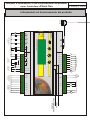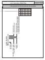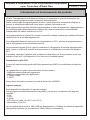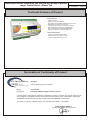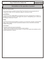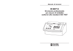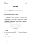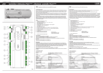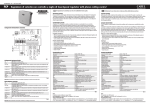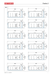
1
serie µPlanet Two
Controllore Digitale programmabile
con µLadder IDE
µPlanet Two series
Digital Controller programmable
via µLadder IDE
!
Informazioni di rinuncia:
Non rimuovere le etichette di identificazione!
La garanzia decade per i controlli privi di etichette identificative.
Grazie per la vostra collaborazione.
Disclaimer notice:
Don't remove the labels of identification!
The warranty is void for the controller without labels.
Thank you for your cooperation.
Istruzioni d’installazione, d’uso e manutenzione del prodotto
serie: Controllore µPlanet Two
FILE:ISQ-0306.CDR
ND
2^ EDIZIONE / 2
EDITION
Caratteristiche Costruttive del Prodotto
Caratteristiche generali:
- Controllore Digitale;
- Alimentazione 1~ 24V±10% 50/60Hz;
- Contenitore di tipo termoplastico Noryl UL 94 V-0;
- Supporti per il fissaggio su pannello;
- Temperatura di funzionamento -5°C/+40°C (-5/+40TW);
- Umidità massima 50% a +40°C (MD50/T40);
- Dimensioni 159,5x90x53 mm (DIN 43880 Standard);
- Grado di protezione: frontale IP52, posteriore IP20.
Informazioni tecnico-costruttive:
- Tensione di isolamento nominale 300V~;
- Tensione nominale dei circuiti ausiliari:
- circuiti di controllo: 5Vdc e 3,3Vdc.
Dichiarazione di Conformità del Prodotto
Elettrotecnica
GRIG S.r.l.
Water, Air and Cooling Control
Dichiara
che il presente prodotto da essa fornito
Serie di appartenenza: µPlanet Two
Descrizione:
Controllore Digitale liberamente programmabile
è pienamente conforme ai requisiti di protezione in materia di sicurezza (apparecchi in bassa tensione)
e di compatibilità elettromagnetica previsti dalle Direttive della Comunità Europea 73/23/CEE del 19/02/1973,
89/336/CEE del 03/05/1989, 92/31/CEE del 28/04/1992 e 93/68/CEE del 22/07/1993.
La presente conformità viene rilasciata riferita alle Norme: EN 50081-1, EN 50082-1.
Elettrotecnica GRIG S.r.l.
Il Presidente Giovanni Conte
HOT KEY
PORTA DI
PROGRAMMAZIONE
ADC 0
ALIMENTAZIONE
24V
ADC 1
~
AI3
ADC 2
AI2
DAC 1
ADC 3
IN1
IN0
Out GNDD
USCITA
PWM
DAC 0
PWM0
INGRESSI PULITI
24V
CH0_230V
~
SSR0
CH4_24V
SSR1
INGRESSI DIGITALI 24V~
24V
~ ~
230V
CH1_24V
+5V +20V AO1 AO2
CH2_24V
AI4
CH3_24V
GNDA AI1
CH1_230V
CH0_24V
USCITE SSR
2A 24V~
CH5_24V
INGRESSI
DIG. 230V~
Out0
CH6_24V
USCITE
ANALOGICHE
CH7_24V
INGRESSI
ANALOGICI
Out2
A
+
B
µ P 2
Micro
Planet
T w o
Out4
~
230V
www.grig.it
Out3
4x20 LCD Built-In Terminal
Out1
USCITE
DIGITALI 6A 250V~
12345678
RJ45
Istruzioni d’installazione, d’uso e manutenzione del prodotto
serie: Controllore µPlanet Two
FILE:ISQ-0306.CDR
2^ EDIZIONE / 2
ND
Informazioni sul funzionamento del prodotto
EDITION
senza RTC = 0
con RTC = 1
2 Relè SPDT + 3 SPST + 2 SSR = 0
2 Relè SPDT + 5 SPST = 1
ADC 10Bit = A
ADC 12Bit = B
Codice Prodotto
MP2A x A 0 x x x x A
0 = Senza terminale built-in
1 = Terminale built-in 2x16 colore nero/giallo
5 = Terminale built-in 4x20 colore nero/giallo
6 = Terminale built-in 4x20 colore bianco/blu
0 = Connettori a vite
1 = Connettori sconnettibili
Rx-/Tx- (2)
8
Rx-/Tx- (1)
Rx+/Tx+ (2) Rx+/Tx+ (1)
Rx2 (RS232)
7
+5Vcc
4
Tx2 (RS232)
Rx (TTL) Rx1 (RS232)
+5Vcc
3
GND “D”
6
GND “D”
2
+5Vcc
Tx (TTL) Tx1 (RS232)
GND “D”
1
Porta B
5
Porta A
PIN
Istruzioni d’installazione, d’uso e manutenzione del prodotto
serie: Controllore µPlanet Two
FILE:ISQ-0306.CDR
2^ EDIZIONE / 2
Informazioni sul funzionamento del prodotto
ND
EDITION
Istruzioni d’installazione, d’uso e manutenzione del prodotto
serie: Controllore µPlanet Two
FILE:ISQ-0306.CDR
ND
2^ EDIZIONE / 2
EDITION
Informazioni sul funzionamento del prodotto
µPlanet Two rappresenta una valida soluzione per l'integrazione su piccole automazioni che
vengono spesso gestite da singoli componenti elettromeccanici.
Grazie al linguaggio di programmazione µLadder, questo dispositivo consente di integrare le
funzioni di componenti tradizionali come timers, contatori, termostati e relè.
Esso rappresenta un perfetto connubio tra performance e livello di integrazione, raggruppando in
un contenitore dalle ridotte dimensioni (9 Moduli Din) anche le periferiche ormai diventate
indispensabili nell’utilizzo ordinario di un PLC.
La programmazione di µPlanet Two tramite il pacchetto software µLadder per ambiente Windows
risulta intuitiva e di semplice applicazione.
Sono disponibili Starter-Kit economici che comprendono un PLC, software di programmazione,
cavi di collegamento e documentazione tecnica.
Le porte seriali integrate (fino a 4 porte) consentono il collegamento ai terminali operatore della
serie µVision e X-Terminal, nonché la comunicazione in modalità slave su protocollo ModbusRTU.
E’ possibile, attraverso l’apposito tool, predisporre il dispositivo per la connessione in rete con
scambio di dati trà 2 o più dispositivi (di cui uno solo in modalità master)
Caratteristiche della CPU
Il cuore del sistema risulta gestito dall’ultima generazione di MPU con architettura derivata da
80c51.
Le caratteristiche di questo microcontrollore risultano essere:
- 64KBytes memoria flash per programma;
- 4KBytes memoria Ram per applicazioni;
- 5 Timers a 16Bit;
- 2 UART.
L’esecuzione del codice avviene con picchi di lavoro fino a 25MIPS.
Ingressi analogici
Sono disponibili nel dispositivo 4 ingressi analogici.
Tutti gli ingressi risultano liberamente configurabili (uno ad uno) via software nelle seguenti
modalità:
- 0-1V;
- 0-10V;
- 4-20mA;
- NTC Grig con scala -10/+90°C o 0/+150°C;
- Raziometrici (0,5-4,5V).
La conversione tipica risulta a 10Bit (9 Bit per Raziometrico) e 100Ksps. A richiesta è disponibile
una specifica versione con conversione a 12Bit (11Bit per raziometrico).
Istruzioni d’installazione, d’uso e manutenzione del prodotto
serie: Controllore µPlanet Two
FILE:ISQ-0306.CDR
ND
2^ EDIZIONE / 2
EDITION
Informazioni sul funzionamento del prodotto
2 specifici morsetti risultano dedicati all’alimentazione dei trasduttori con tensione continua di
+20Vdc (max. 50mA) e +5Vdc (max. 50mA).
Ingressi digitali
µPlanet Two, oltre agli ingressi analogici sopra riportati, integra già 12 ingressi digitali,
configurabili via software come n.a. o n.c., di cui 2 di tipo “pulito”, 8 a 24V~/= e 2 a 230V~.
Uscite digitali
µPlanet Two risulta attualmente disponibile in 2 versioni:
1) con 5 relè elettromeccanici, di cui 2 di tipo SPDT e 3 di tipo SPST n.a., e 2 relè di tipo SSR;
2) con 7 relè elettromeccanici, di cui 2 di tipo SPDT e 5 di tipo SPST n.a..
Oltre alle uscite a relè, è disponibile, già integrata una uscita di tipo PWM (Pulse With
Modulation) per gestione di dispositivi di comando come, ad esempio, regolatori di velocità a
taglio di fase, ecc..
A richiesta, risulta disponibile una periferica aggiuntiva che consente di convertire l’uscita PWM
in uscita a relè elettromeccanico di tipo SPDT, permettendo così l’incremento del numero di
uscite digitali.
Uscite analogiche
µPlanet Two integra di serie 2 uscite analogiche con segnale 0-10Vdc e risoluzione 12Bit, usabili
ad esempio per il comando di inverter di frequenza.
Terminale Built-In
Tutte le versioni possono essere ordinate anche con display e tasti integrati consentendo un
contenimento della spesa delle apparecchiature e l’eliminazione del terminale remoto.
A seconda del modello il prodotto puo’ includere pertanto:
- 1 display LCD retroilluminato con 2 righe da 16 caratteri ciascuna o 4 righe da 20 caratteri
ciascuna, entrambi con due possibili colorazioni;
- 4 tasti per la gestione ed impostazione di parametri e password.
Anche il terminale built-in è programmabile mediante µLadder.
Interfacce di comunicazione
La serie include come standard 2 connettori di tipo RJ45 che consentono la comunicazione
attraverso varie tipologie di porte (Rs485, Rs232, TTL) con i vari Terminali remoti, convertitori di
interfaccia, periferiche di terze parti o sistemi scada.
Vi preghiamo di notare che la porta TTL non risulta attualmente abilitate. Per la verifica sul loro
reale stato e/o gestione contemporanea, contattare in nostro Ufficio Tecnico.
Nei connettori risulta già disponibile la tensione di alimentazione per i terminali remoti da noi
prodotti.
Istruzioni d’installazione, d’uso e manutenzione del prodotto
serie: Controllore µPlanet Two
FILE:ISQ-0306.CDR
ND
2^ EDIZIONE / 2
EDITION
Informazioni sul funzionamento del prodotto
Modulo Real Time Clock
L’unità prevede una versione completa di modulo Real Time Clock (orologio a tempo reale),
gestibile e parametrizzabile da µLadder.
L’opzione deve essere richiesta in fase d’ordine.
EEProm seriali
Risultano già integrate nel dispositivo 2 EEProm seriali da 64K bit cadauna, entrambi gestibili
via µLadder, per operazione di datalogger a basso livello di informazioni, con cicli di
lettura/scrittura fino a 1 milione e ritenzione dei dati fino a 40 anni.
HotKey
Risulta già prevista la connessione hardware ad una chiavetta esterna, mediante connettore Mini
USB, per il trasferimento di dati o parametri tra vari controllori (funzionalità disponibile nel corso
del 2006).
Connessioni
La serie prevede due tipologie di connessioni:
- mediante connettori fissi a viti, pensata per il contenimento dei costi del prodotto;
- mediante connettori sconnettibili, pensata per velocizzare l’installazione e l’eventuale
sostituzione del prodotto.
Istruzioni d’installazione, d’uso e manutenzione del prodotto
serie: Controllore µPlanet Two
FILE:ISQ-0306.CDR
ND
2^ EDIZIONE / 2
EDITION
Installazione
Avvertenze generali
1. Assicurarsi che la tensione di alimentazione sia compatibile con l’apparecchiatura da installare e che la linea sia protetta
secondo le normative in vigore;
2. Accertarsi che le caratteristiche tecniche del motore che deve essere connesso siano corrispondenti a quelle dichiarate per il
modello della scheda;
3. Verificare che la scheda venga installata in ambienti richiedenti grado di protezione corrispondente o inferiore a quello
dichiarato per l’apparecchiatura;
4. Per il fissaggio della scheda usare esclusivamente le staffe fornite a corredo;
5. Al termine del fissaggio verificare che non vi siano impurità all’interno del quadro e che i componenti non siano stati
danneggiati accidentalmente; in caso contrario contattare il ns. Ufficio Vendite per la riparazione o sostituzione del pezzo;
6. Per la connessione elettrica (che deve essere effettuata solo da personale specializzato) seguire scrupolosamente lo schema
elettrico verificando che la sezione dei cavi e terminazioni siano corrispondenti a quanto richiesto;
7. Lavorare in sicurezza disconettendo prima dell’installazione tutti gli elementi che possono portare tensione alla scheda;
8. Prima di attivare la scheda effettuare la taratura delle protezioni secondo tabella;
9. In fase di verifica del funzionamento dell’apparecchiatura, in caso di intervento delle protezioni, escludere l’alimentazione e
verificare le cause di allarme prima di ripristinare le protezioni stesse.
10. In caso di guasti e/o rotture far sostituire i componenti da personale specializzato con altri aventi pari caratteristiche o
eventualmente contattare il ns. Servizio Riparazioni.
11. Non rimuovere le etichette di identificazione.
Riduzione dei disturbi
Per la riduzione dei disturbi rilevati, in particolare per i segnali analogici, provvedere a cablare il dispositivo secondo gli
accorgimenti di seguito descritti:
- separare quanto più possibile i cavi dei segnali delle sonde e degli ingressi digitali dai cavi dei carichi induttivi e di potenza per
evitare possibili disturbi elettromagnetici.
- non inserire mai nelle stesse canaline cavi di potenza e i cavi delle sonde.
- evitare che i cavi delle sonde siano installati nelle immediate vicinanze di dispositivi di potenza (contattori, interruttori
magnetotermici, relè termici, invertre, ecc.);
- ridurre il più possibile il percorso dei cavi dei sensori ed evitare che compiano percorsi a spirale che racchiudano all’interno
dispositivi di potenza.
- è preferibile che il collegamento delle sonde sia costituito da cavi schermati, con sezione minima raccomandata pari a 0,5 mmq
per ciascun conduttore;
- preferire, ove possibile, l’uso di prodotti da noi forniti o indicati che risultano pertanto compatibili con i nostri sistemi in quanto
verificati già in fase di progettazione;
Consigliamo di verificare inoltre il rispetto delle seguenti indicazioni:
- evitare di toccare con le dita i componenti elettronici montati sulle schede per evitare scariche elettrostatiche dall'operatore
verso i componenti stessi. A questo proposito raccomandiamo l’installazione dei dispositivi secondo procedure e in ambienti
ESD;
- evitare il montaggio delle schede negli ambienti che presentino elevate interferenze magnetiche e/o radiofrequenze.
Per caratteristiche e modalità d’uso non integrate in questa istruzione si rimanda alla versione del catalogo in vigore alla data di
emissione della presente
Il fatto che l’apparecchiatura è stata sottoposta regolarmente a prove da parte del costruttore, non esonera l’installatore dall’obbligo
della verifica della stessa dopo la sua installazione.
Il costruttore declina ogni responsabilità per sinistri a cose o a persone derivanti da manomissioni delle apparecchiature da parte di
personale non autorizzato ovvero da carenze di manutenzione o riparazione.
Questa apparecchiatura non è adatta al controllo di macchinari da cui dipenda la vita di persone.
Istruzioni d’installazione, d’uso e manutenzione del prodotto
serie: Controllore µPlanet Two
FILE:ISQ-0306.CDR
ND
2^ EDIZIONE / 2
EDITION
Condizioni generali di garanzia per le apparecchiature
Garanzia: la garanzia ha validità di mesi 12, a partire dalla data di acquisto, comprovato dall'esibizione di
scontrino o bolla fiscale e comunque non oltre 16 mesi dalla data di fabbricazione dell'apparecchiatura.
Riparazioni: le riparazioni sono coperte da garanzia sui materiali sostituiti o riparati per 6 mesi dalla data di
spedizione.
Più in generale, la garanzia copre la riparazione e la sostituzione di parti riconosciute difettose da Elettrotecnica
Grig S.r.l. e la riparazione verrà eseguita presso il ns. Centro Assistenza Riparazioni o presso centri assistenza
esterni abilitati da Elettrotecnica Grig S.r.l..
In caso di riparazione presso i Centri Assistenza, anche nel periodo di garanzia, i prodotti dovranno essere
inviati in porto franco e verranno restituiti in porto assegnato.
Per assistenza a domicilio, in sede del cliente, contattare il ns. servizio riparazioni:
Tel: 049 9704453 Fax: 049 9703025 e-mail: [email protected]
In ogni caso, la Elettrotecnica Grig S.r.l. declina ogni responsabilità per danni a cose, persone e animali derivanti
da problemi di natura costruttiva non riconducibili a errori di fabbricazione interna.
La garanzia decade:
- se l'apparecchiatura è stata riparata, smontata e/o manomessa da persone da noi non autorizzate;
- se il guasto sia stato provocato da errori di collegamento elettrico/idraulico/meccanico o da mancata o
inadeguata protezione e rispetto delle normative vigenti;
- se il prodotto sia stato sovraccaricato oltre i limiti di targa;
- se i componenti interni e/o esterni siano a contatto con liquidi abrasivi/infiammabili/corrosivi, ecc…;
- se siano intervenuti fattori quali terremoti, inondazioni (calamità naturali);
- se i materiali siano danneggiati a causa del normale logoramento;
- se l'apparecchiatura non abbia avuto una regolare manutenzione (normalmente verifica ogni 6 mesi);
Elettrotecnica Grig S.r.l. si riserva l'insindacabile giudizio sulla causa che ha prodotto il guasto e se lo stesso
rientri nei casi previsti per il conseguimento della garanzia.
Complimentandoci per l'acquisto di questo prodotto, restiamo a completa disposizione per qualsiasi
chiarimento.
Instructions for the installation, the use and the upkeep of product
range: Control device µPlanet Two
FILE:ISQ-0306.CDR
ND
2^ EDIZIONE / 2
EDITION
Technical Features of Product
General features:
-
Digital controller;
Supply 1~ 24V±10% 50/60Hz;
Box made of thermoplastic material Noryl UL 94 V-0;
Supports to fix the device to the panel;
Temperature of working -5°C/+40°C (-5/+40TW);
Maximal dampness 50% at 40°C (MD50/T40);
Size 159,5x90x53 mm (DIN 43880 Standard);
Degree of protection: front IP52, back IP20.
Technical Information:
- Tension of nominal insulation 300V;
- Nominal tension of auxiliary circuits:
- control circuits: 5Vdc and 3,3 Vdc.
Declaration of Conformity of Product
Elettrotecnica
GRIG S.r.l.
Water, Air and Cooling Control
Range:
Description:
Declares
that the following product supplied
µPlanet Two
Free-programmable digital electronic control
conforms quite to the protection necessary qualification in subject of security (low tension devices) and
electromagnetic compatibility required by the Directives of European Union 73/23/CEE of 19/02/1973,
89/336/CEE of 03/05/1989, 92/31/CEE of 28/04/1992 and 93/68/CEE of 22/07/1993.
The present conformity released refers to the Normatives: EN 50081-1, EN 50082-1.
Elettrotecnica GRIG S.r.l.
The General Director Giovanni Conte
HOT KEY
PROGRAMMING
PORT
ADC 0
SUPPLY
24V
ADC 1
~
AI3
ADC 2
AI2
DAC 1
ADC 3
IN1
IN0
Out GNDD
PWM
OUTPUT
DAC 0
PWM0
FREE VOLTAGE
INPUTS
24V
CH0_230V
~
SSR0
CH4_24V
SSR1
24V~ DIGITAL
INPUTS
24V
~ ~
230V
CH1_24V
+5V +20V AO1 AO2
CH2_24V
AI4
CH3_24V
GNDA AI1
CH1_230V
CH0_24V
2A 24V~ SSR
OUTPUTS
CH5_24V
230V~ DIG.
INPUTS
Out0
CH6_24V
ANALOG
OUTPUTS
CH7_24V
ANALOG
INPUTS
Out2
A
+
B
µ P 2
Micro
Planet
T w o
Out4
~
230V
www.grig.it
Out3
4x20 LCD Built-In Terminal
Out1
6A 250V~
DIGITAL OUTPUTS
12345678
RJ45
Instructions for the installation, the use and the upkeep of product
range: Control device µPlanet Two
FILE:ISQ-0306.CDR
2^ EDIZIONE / 2
ND
Information on the operation of product
EDITION
without RTC = 0
with RTC = 1
2 Relays SPDT + 3 SPST + 2 SSR = 0
2 Relays SPDT + 5 SPST = 1
ADC 10Bit = A
ADC 12Bit = B
Product Code
MP2A x A 0 x x x x A
0 = without built-in terminal
1 = Black/Yellow-coloured 2x16 built-in terminal
5 = Black/Yellow-coloured 4x20 built-in terminal
6 = White/Blue-coloured 4x20 built-in terminal
0 = Screws type connectors
1 = Removable type connectors
Rx-/Tx- (2)
8
Rx-/Tx- (1)
Rx+/Tx+ (2) Rx+/Tx+ (1)
Rx2 (RS232)
7
+5Vcc
4
Tx2 (RS232)
Rx (TTL) Rx1 (RS232)
+5Vcc
3
GND “D”
6
GND “D”
2
+5Vcc
Tx (TTL) Tx1 (RS232)
GND “D”
1
Port B
5
Port A
PIN
Instructions for the installation, the use and the upkeep of product
range: Control device µPlanet Two
FILE:ISQ-0306.CDR
2^ EDIZIONE / 2
Information on the operation of product
ND
EDITION
Instructions for the installation, the use and the upkeep of product
range: Control device µPlanet Two
FILE:ISQ-0306.CDR
ND
2^ EDIZIONE / 2
EDITION
Information on the operation of product
µPlanet Two represents a valid solution for the integration on the small automations that are often
managed by electromechanical single components.
Thanks to the language of programming µLadder, this device permits to integrate the operations
of traditional components such as timers, meters, thermostats and relays.
It represents a perfect connubial between performance and level of integration, because it
assembles in a reduced/small-size box (9 Din modules) also the peripherals that have become
essential now in the ordinary use of a PLC.
The programming of µPlanet Two by the software package µLadder for Windows environment is
intuitive and so very easy in the application.
The economic Starter-Kits are available and they include a PLC, software of programming,
connection cables and technical documents.
The integrated serial ports (up to 4 ports) permit both the connection to the terminals operators of
range µVision and X-Terminal and the communication in slave mode on protocol Modbus-RTU.
It is possible to get a connection device in the network with the exchange of data between 2 or
more devices (only one of which in master mode).
Characteristics of CPU
The heart of system is managed by the last generation of MPU with a structure derived from
80c51.
The characteristics of this microcontroller are the following:
- 64KBytes flash memory for program;
- 4Kbytes Ram memory for applications;
- 5 16Bit Timers;
- 2 UART.
It can make the code with peaks of work up to 25MIPS.
Analog inputs
4 analog inputs are available in the device.
All the inputs can be freely configurable (each by each) via software in the following modes:
- 0-1V;
- 0-10V;
- 4-20mA;
- NTC Grig with scale -10/+90°C or 0/+150°C;
- Ratiometric (0,5-4,5V).
The typical conversion is that to 10Bit (9 Bit for ratiometric) and 100Ksps. On request, a specific
version is available with conversion to 12Bit (11Bit for ratiometric).
2 specific connecting terminals supplies the transducers with a direct voltage of + 20Vdc (max.
50mA) or +5Vdc (max. 50mA).
Instructions for the installation, the use and the upkeep of product
range: Control device µPlanet Two
FILE:ISQ-0306.CDR
ND
2^ EDIZIONE / 2
EDITION
Information on the operation of product
Digital inputs
µPlanet Two, besides the above analog inputs, integrates the following 12 digital inputs :
- 8 24V~/= inputs;
- 2 230V~ inputs;
- 2 free voltage inputs.
These inputs can be configured via Software as normal open or normal closed.
Digital outputs
Actually µPlanet Two is available in two versions:
- 1 with 5 electromechanical relays (2 SPDT type relay and 3 SPST normal open type relay) and
2 SSR type relay;
- 1 with 7 electromechanical relays (2 SPDT type relay and 5 SPST normal open type relay).
Besides the relay outputs, a PWM type already integrated (Pulse With Modulation) to manage
the control devices such as, for instance, the speed regulator in cut phase, etc.
As request, an additional peripheral is available that permits to convert the PWM output into the
output of SPDT type electromechanical relay.
This peripheral permits the increase of digital outputs number.
Analog Outputs
µPlanet Two in its standard version integrates 2 analog outputs with a signal range of 0-10Vdc
and the 12 Bit resolution, that can be used for instance to control frequency inverters.
Built-In Terminal
You can order all the versions also with display and integrated keys that permit the keeping of
expense for devices such as remote terminal.
This terminal, the Built-in Terminal, is programmable through µLadder.
According to the model the product can include:
- 1 backlight LCD built-in display type with 2 lines of 16 characters/each or one with 4 lines of 20
characters/each, both of them with 2 possible colours;
- 4 keys for the managing and setting of parameters and passwords.
Communication Interfaces
The range includes as standard 2 RJ45 type connectors that permit the communication through
various typologies of ports (Rs485, Rr232, TTL) with various remote Terminals, interface
converters, peripherals manufactured by a third party or scada systems.
Please, note that actually TTL port is not available. For its use and information on it you can
contact directly our technical office.
In the connectors the voltage of supply is available for the remote terminals supplied by us.
Instructions for the installation, the use and the upkeep of product
range: Control device µPlanet Two
FILE:ISQ-0306.CDR
ND
2^ EDIZIONE / 2
EDITION
Information on the operation of product
Real Time Clock module
The unit can include a complete version of Real Time Clock that can be programmed and
managed by µLadder. You can request this optional in the phase of order.
Serial EEProm
The device includes 2 64KBit EEProms integrated, that can be managed both by µLadder, for
operation of low level information data logger, with cycles of reading/writing up to 1 million and
the stoppage of data up to 40 years.
Hotkey
The device includes also the hardware connection to an external key, through a connector Mini
USB, in order to transfer the data or parameters between various controllers (functionality
available during 2006).
Connections
The range includes two types of connection:
- fixed by screws, this type permits to keep the costs of product;
- through connectors that can be disconnected , this type makes easier the installation and the
eventual replacement of product.
Instructions for the installation, the use and the upkeep of product
range: Control device µPlanet Two
FILE:ISQ-0306.CDR
ND
2^ EDIZIONE / 2
EDITION
Upkeep
General Warning
1. Assure that the supply tension is compatible with the devices to install and that the network is protected according to the
normative in force.
2. Assure that the technical characteristics of motor to be connected correspond to those declared for the model of the board;
3. Verify that the board is installed in the environments requiring the degree of protection that corresponds or that is lower than
that declared for the devices;
4. In order to fix the board use exclusively brackets supplied as additional equipment
5. At the end of fixing verify the presence of impurities inside the panel and that the components have not been accidentally
damaged, otherwise contact our Sales Department in order to repair or replace the piece;
6. For the electric connection (that has to be made only by specialized personnel) follow very carefully the electrical scheme
verifying that the cable section and terminals corresponds to the requirement.
7. Work in security by disconnecting before installation all the elements that can bring tension to the board.
8. Before activating the board calibrate the protections according to the scale;
9. While you are verifying the functioning of devices, in case of protections' intervention, exclude the supply and verify the causes
of alarms before re-introducing the protections.
10. In case of damages and/or bursts, specialized personnel or eventually our Repairing Service has to replace the components
of product.
11. Don't remove the labels of identification.
Reduction of disturbs
For the reduction of disturbs relieved, in particular for the analogical signals, provide to cable the device according the following
prescriptions:
- Separate as much as possible the cables of probes and digital inputs' signals from the cables of inductive loads and of power in
order to avoid the possible electromagnetic disturbs.
- Never insert in the same cable run channels both power cables and probes cables.
- Avoid installing the cables of probes near the power devices (contactors, circuit breakers, thermal relays, inverters, etc.);
- Reduce as soon as possible the way of sensors' cables and avoid making spiral ways surrounding inside the power devices
- It is preferable that the connection of probes consists of schemed cables, with a minimal recommended section that
corresponds to 0,5sqmm for each conductor;
- Prefer, where it is possible, the use of products supplied by Elettrotecnica Grig Srl or indicated so that they result compatible
with our systems since they have already been tested in phase of project.
In addition we advise to verify the respect of the following indications:
- Avoid touching with fingers the electronic components placed on boards in order to avoid electrostatic discharge by operator
toward the same components. On this subject we recommend the installation of devices according the procedures and in ESD
environments;
- Avoid assembling the boards in environments that present high magnetic interferences and/or radiofrequencies.
As regards characteristics and modalities of use not supplied in these instructions we refer to the catalogue version in force from the
date of issuing the present.
The fact that the devices have been submitted regularly to tests by the constructor does not exempt who installs the device from the
duty of verifying it after the installation.
The constructor declines any liability for accidents occurred to things and people and deriving from the unduly opening of devices by
not authorized personnel or by the lack of upkeep or repair.
This device does not suit the control of machinery which people's life depends on.
Instructions for the installation, the use and the upkeep of product
range: Control device µPlanet Two
FILE:ISQ-0306.CDR
ND
2^ EDIZIONE / 2
EDITION
General conditions of guarantee for the devices
Guarantee: the guarantee is being valid for 12 months, from the date of purchase, vouched by the exhibition of
delivery note and not further than 16 months from the date of the device manufacturing .
Repair: the repairs are covered by guarantee on the replacement or the repair of material from the date of
dispatch.
More in general, the guarantee covers the repair and the replacement of the parts recognized faulty by
Elettrotecnica Grig. Our Repair Assistance or the Assistance centre entitled by us will provide with the repair and
the replacement.
In case of repair by our Repair Assistance, even in the period of guarantee, you have to send products carriage
paid and we return them carriage forward.
For assistance at the buyer's residence, you can contact our repair service:
Tel: 049 9704453 Fax: 049 9703025 e-mail: [email protected]
In any case, Elettrotecnica Grig S.r.l. declines every liability for damages to things, people or animals, when these
damages derive from problems of manufacturing nature that cannot be attributed to mistakes of internal
manufacturing.
The guarantee lapses:
- If the product has been repaired, dissembled and/or unduly opened by people not authorized by Elettrotecnica
Grig Srl.
- If the damage has been caused by mistakes of electrical/hydraulic/mechanical or by missing or improper
protection and respect of the normative in force.
- If the product has been overcharged beyond the limits indicated in the specifics reported above.
- If the internal components and/or external are in contact with abrasive/inflammable/corrosive liquids, etc…;
- In case of natural calamities such as earthquakes, inundations etc.
- If the product is damaged by the normal wear;
- If the product has not had a regular upkeep that normally includes a test every 6 months
Eletrotecnica Grig S.r.l. reserves the incontrovertible judgment on the cause that has produced the damage and
on the fact that the same damage is within the cases for the achievement of guarantee.
We congratulate you on the purchase of this product and we are at your complete disposal for any
question and clarification.