1
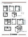
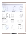
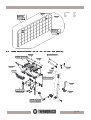
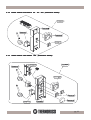
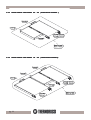
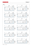
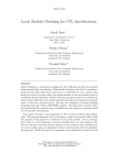
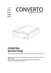
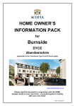
USE AND MAINTENANCE GUIDE
CENTRAL HEATING COOKER
25 - 30 - F25 - F30 - 60 - 65 - 650 - 90 - 95 - 920
36011 Arsiero (vi) ITALY - Via Grumolo, 4 - tel. 0445 741310
www.thermorossi.com
fax 0445741657
DECLARATION OF CONFORMITY
CONTENTS
1.
INTRODUCTION .................................................................................................................................................................................
1.1
General guidelines .............................................................................................................................................................
1.2
Safety guidelines ................................................................................................................................................................
1.3
Standards and recommendations .....................................................................................................................................
1.4
Transport and storage ........................................................................................................................................................
2.
TECHNICAL CHARACTERISTICS ....................................................................................................................................................
2.1
Vitrification. .........................................................................................................................................................................
3.
GENERAL DESCRIPTION ..................................................................................................................................................................
3.1
Operating principle ............................................................................................................................................................
3.2
Wood fuel ............................................................................................................................................................................
4.
INSTALLATION ..................................................................................................................................................................................
4.1
Locating your Bosky central heating cooker. ...................................................................................................................
4.2
Installing the safety heat exchanger (only for 25 - 30 - F25 - F30 ) ................................................................................
4.3
Wiring diagram
25 - 30. ...............................................................................................................................................
4.4
Wiring diagram F25 - F30. ..............................................................................................................................................
4.5
Wiring diagram 60 - 65 - 650 - 90 - 95 - 920 without electric oven .................................................................................
4.6
Wiring diagram 60 - 65 - 650 - 90 - 95 - 920 with electric oven ......................................................................................
4.7
Guidelines for the hydraulic connections of the central heating cooker to the boiler coils ..........................................
4.8
Guidelines for the hydraulic connections of the central heating cooker to the boiler tubes with interspacing ...........
4.9
Recommendations for the execution of the hydraulic and electric system ....................................................................
4.10
Installation of casing for Bosky 25-30-F25-F30. ..............................................................................................................
5.
OPERATION .........................................................................................................................................................................................
5.1
Description of parts and main controls of the central heating cookers ..........................................................................
5.2
Lighting and starting the central heating cookers ............................................................................................................
5.3
Operation of the central heating cookers .........................................................................................................................
5.4
Grate positions in the central heating cookers ..................................................................................................................
5.5
How to use the oven in central heating cookers F25-F30-60-90-920 .............................................................................
5.6
The fold-away towel rack (only for 25 - 30 - F25 - F30 ) ..................................................................................................
6.
CLEANING AND MAINTENANCE ......................................................................................................................................................
6.1
General cleaning ................................................................................................................................................................
6.2
Ash ...............................................................................................................................................................................................
6.3
How to clean the radiant plate ....................................................................................................................................................
6.4
How to replace the oven light bulb .............................................................................................................................................
6.5
Recommendations ......................................................................................................................................................................
7.
SMOKE EXHAUST PIPE .....................................................................................................................................................................
7.1
General. ..............................................................................................................................................................................
7.2
Essential requirements for the chimney cap ....................................................................................................................
7.3
Ventilation of the rooms .....................................................................................................................................................
7.4
Connection with the flue outlet ...........................................................................................................................................
8.
TROUBLESHOOTING .........................................................................................................................................................................
8.1
Problems, causes and remedies for Bosky central heating cookers .............................................................................
9.
SPARE PARTS ..................................................................................................................................................................................
“EC” DECLARATION OF CONFORMITY
In accordance with the following directives:
European Directive
73/23
/ EEC and its amending directive
89/336 / EEC and its amending directives
93/68/EEC
93/68/EEC
92/31/EEC
93/97/EEC
Thermorossi S.p.A. of Via Grumolo 4 – ARSIERO (VI), on its own responsibility, declares that the central heating cookers of the F25 , F30, 25 ,
30, 60 , 65 , 650 , 90 , 95 , 920 series have been designed and built in compliance with the safety requirements of CE marking standards. This
declaration refers to the complete range of products in the specified series.
ARSIERO, 1 March 2003
pg. 2
THERMOROSSI S.p.A.
1
INTRODUCTION
1.1
GENERAL GUIDELINES
This installation, use and maintenance guide is an integral and essential part of the product and must be kept by the user. Before commencing
with the installation, use and maintenance of the product, carefully read all the instructions contained in this booklet. This appliance must only be
used as intended by the manufacturer. Any other use is considered incorrect and therefore hazardous; consequently, the user shall be totally
liable for the product if used improperly.
Installation, maintenance and repairs must be carried out by personnel with professional qualifications and in compliance with current regulatory
standards and in accordance with the instructions of the manufacturer of the appliance. Use only original spare parts. Incorrect installation or
poor maintenance could injure or damage people, animals or things; in this case the manufacturer shall be relieved of all responsibility. Before
commencing any cleaning or maintenance operation ensure that the appliance has been disconnected from the mains power supply by means
of the main system switch or some other disconnecting device installed upstream from the appliance. The product must be installed in locations
suitable for fire-fighting and furnished with all the services (power and outlets) which the appliance requires for a correct and safe operation.
If the appliance is sold or transferred to another user ensure that the guide is handed over with it.
Thermorossi S.p.A. maintains the author’s rights on these service instructions. The information in this booklet may not be reproduced or given
to third parties or used for competitive purposes without the appropriate authorization.
1.2 SAFETY GUIDELINES
PERSONAL INJURY
This safety symbol identifies important messages throughout the manual. When you come across this symbol, read the
following message carefully. Users of the central heating cooker must adhere strictly to the instructions to avoid serious
injury.
DAMAGE TO PROPERTY
This safety symbol identifies messages or instructions that are essential for the correct operation of the cooker and
heating system. These guidelines must be observed scrupulously to avoid serious damage to both the cooker
and the heating system.
INFORMATION
This safety symbol signals instructions that are important for the good operation of the cooker and/or heating
system. The appliances will not function correctly if the instructions are not observed correctly.
1.3
ST
AND
ARDS
TAND
ANDARDS
AND
RECOMMEND
ATIONS
RECOMMENDA
•Normative references: national and international standards used as reference guides for the design, industrialization and
production of the products indicated in this manual
– European Directive 73/23/EEC
–
standard CEI 61/50
– European Directive 93/68/EEC
–
standard CEI EN 60204
– European Directive 89/336/EEC
–
standard CEI64-8 (IEC364)
RECOMMENDATIONS:
Before using the appliance, carefully read every section of this instruction manual as knowledge of the information and the regulations contained
in it are essential for a correct use of the appliance.
The entire operation concerning the connection of the electric panel must be carried out by expert personnel; no responsibility will be accepted
for damages, even to third parties, if the instructions for installation, use and maintenance of the appliance are not followed scrupulously.
Modifications made to the appliance by the user or on his behalf, must be considered to be under his complete responsibility.
The user is responsible for all the operations required for the installation and maintenance of the appliance before and during its use.
GENERAL WARNINGS
Caution: the appliance must be connected to a system provided with a PE conductor (in compliance with the specifications of 73/23/EEC, 93/
98/EEC, concerning low voltage equipment). Before installing the appliance check the efficiency of the earth circuit of the power supply system.
Caution
Caution: the power supply line must have a section which is suitable for the power of the equipment. The cable section must in any case be
no less than 1.5 mm2. The central heating cooker requires a power supply of 220-240 V and 50 Hz. Voltage variations 10% above or below the
nominal value can cause irregular operation or damage to the electrical device. Ensure that a suitable differential switch is installed upstream from
the equipment.
1.4
TRANSPOR
T AND ST
ORA
GE
ORAGE
TRANSPORT
STORA
•Packaging
•Transport and handling
•Storage
The central heating cookers models 25-30-F25-F30 are packaged in a wooden crate, whereas the other
models are packaged in a cardboard box.
The central heating cooker must be kept in a vertical position and moved exclusively by means of trolleys;
take particular care not to damage the glass components.
The central heating cooker must be stored in humid free environments sheltered from the weather; it is
inadvisable to store the central heating cooker directly on the floor.
pg. 3
TECHNICAL CHARACTERISTICS
642
126
Scarico termico 1/2 "
636
75
714
310
669
707
71
785
Andata 1" 1/4
869
482
Ritorno 1" 1/4
Attacco camino O 150
Legenda
Attacco
Camino
Andata
Ritorno
Scarico
termico
Key
Flue outlet
connection
Delivery
Return
Thermal
discharge
mod. BOSKY 25-30
636
1055
482
126,4
Andata 1" 1/4
Scarico termico1/2 "
714
310
669
707
71
785
75
869
2
Ritorno 1" 1/4
482
Attacco caminoO150
mod. BOSKY F25-F30
pg. 4
Legenda
Attacco
Camino
Andata
Ritorno
Scarico
termico
Modello
Vista posteriore
Vista laterale
Vista dall'alto
Caratteristiche
tecniche
Key
Flue outlet
connection
Delivery
Return
Thermal
discharge
Model
Rear view
Side view
View from
above
Technical
Characteristics
pg. 5
TECHN ICAL D ATA
Firebox capacit y
U sef ul capacit y
kW
kW
Heat radiat ion f rom cook t op
kW
BO SKY 650
BO SKY 65
B O S K Y 95
25,3
25,3
29,6
20,9
20,9
24,4
5
5
5
Widt h
mm
600
560
610
635
600
600
850
850
850
Dept h
mm
Height
mm
Feed opening dim .
mm
H 162 X L 184
H 162 X L 184
H 162 X L 184
mm
250
250
300
Firebox dept h m ax
mm
442
442
442
Firebox height m ax
mm
535
535
535
Ov en widt h
mm
Firebox widt h m ax
-
-
-
Ov en dept h
mm
-
-
-
Ov en height
mm
-
-
-
mm
520X480
520X480
520X530
mm
150
15 0
150
670
670
670
Cook t op dim .
Flue out let
D.
Rear sm ok e out let height .
mm
Heat ing connect ions D.
1" 1/4
1" 1/4
1" 1/4
lt
20
20
25
Vac. required by chim ney m m
wat er colum n.
-2
-2
-2
197
18 2
190
Boiler body cont ent
Tot al weigh
Kg
TECHN ICAL D ATA
Firebox capacit y
U sef ul capacit y
kW
kW
Heat radiat ion f rom cook t op
kW
B O S K Y 9 20
B O S K Y 60
B O S K Y 90
29,6
25,3
29,6
24,4
20,9
24,4
7
7
7
Widt h
mm
1110
990
10 4 0
Dept h
mm
635
600
600
Height
mm
850
850
850
Feed opening dim .
mm
H 162 x L 184
H 162 x L 184
H 162 x L 184
Firebox widt h m ax
mm
300
250
300
Firebox dept h m ax
mm
442
442
442
Firebox height m ax
mm
535
535
535
Ov en widt h
mm
360
360
360
Ov en dept h
mm
530
530
530
Ov en height
mm
320
320
320
mm
970x470
900x500
950x500
mm
150
150
150
710
670
670
Cook t op dim .
Flue out let
D.
Rear sm ok e out let height .
mm
Heat ing connect ions D.
1" 1/4
1" 1/4
1" 1/4
lt
25
20
25
Vac. required by chim ney m m
wat er colum n.
-2
-2
-2
295
260
275
Boiler body cont ent
Tot al weigh
pg. 6
Kg
TEC HN IC A L D ATA
Firebox capacit y
B O SKY F25
kW
25,3
20,9
24,4
20,9
7
7
5
1055
1055
642
636
636
636
869
869
869
210x235
210x235
210x235
mm
300
300
300
m ax m m
442
442
442
540
540
540
kW
Heat radiat ion f rom t op k W
mm
Dept h
mm
Height
mm
Feed opening dim . m m
Firebox w idt h
m ax
Firebox dept h
Firebox height
B O SK Y
29,6
U sef ul capacit y
Widt h
B O S K Y F 30
25,3
m ax m m
Ov en w idt h
mm
360
360
-
Ov en dept h
mm
550
550
-
Ov en height
mm
320
320
-
C ook t op dim .
mm
942x525
942x525
525x525
Flue out let D.
mm
150
150
150
707
707
707
1" 1/4
1" 1/4
1" 1/4
27
27
27
Rear sm ok e out let height
mm
Heat ing connect ions D.
Boiler body cont ent
l
Dep.required by chim ney m m
w at er colum n.
Tot al w eight Kg
2.1
-2
-2
-2
304
304
221
25
B O SK Y
30
29,6
24,4
5
642
636
869
210x235
300
442
540
525x525
15 0
707
1" 1/4
27
-2
221
VITRIFICA
TION
AT
The central heating cookers series 25 - 30 - F25 - F30 - 60 - 65 - 90 - 95 can be supplied boiler body with vitrification
treatment. This treatment occurs at very high temperatures that permit the glass and steel to melt into an alloy
that is completely impervious to corrosion attack caused by acid combustion smoke. Vitrification protects the
boiler body from corrosion caused by acid smoke and condensation developed by the combustion of the wood
fuel. The presence of surface defects such as indents, scratches, etc..., do not affect the life or resistance of the
corrosion proofing treatment.
3
GENERAL
DESCRIPTION
3.1
OPERA
TING
OPERATING
PRINCIPLE
•Your central heating cooker has been constructed to satisfy in full all your heating and practical needs.
3.2
THE FUEL
Special attention must be given to the characteristics of the wood: like all biomass generators. The good
performance of the generator depends on the type of wood used and on its degree of seasoning.
The recommended fuel is normal wood having a moisture content of 10-20% and a thermal value of 2500-3500 Kcal/Kg. Using the right fuel, and
knowing which is in fact the most appropriate wood to use, is one of the most important aspects concerning the use of your central heating
cooker in order to prevent damaging it and the flue outlet.
All types of solid fuel are suitable but we recommend using only hard and well-seasoned wood.
We advise against using wet wood or wood that has been seasoned for less than 18/20 months, as it can cause malfunctions and the formation
of tarry deposits, as well as not giving the correct thermal performance. All woods have different heat outputs: for example, 1Kg of beech equals
1.15Kg of birch, 1.6 Kg of fir, 0.5 Kg of briquettes… The heat outputs can also vary considerably depending on the type of fuel used and on the
size of the piece of wood. Using pieces of wood that are too thick cannot guarantee the declared power yield. Do not burn generic waste or
plastic but above all never use petrol or other inflammable liquids. When using briquettes it is mandatory to halve the fuel consumption.
The use of fuel that does not conform to the specifications set out
above immediately invalidates the warranty on the central heating
cooker.
pg. 7
450 mmse
450 mm for aso
timber
ffittoceiling
inlegno
250 mm for a25
masonry
0 mmseceiling
soffitto inmuratura
INST
ALLA
TION
INSTALLA
ALLATION
4.1
L
OCA
TING THE CENTRAL HEA
TING COOKER
LOCA
OCATING
HEATING
A vital aspect to consider is that the flooring of the room in which the central
heating cooker is installed must be capable of bearing the weight of the
central heating cooker.
CAUTION: The room in which the central heating cooker is installed must be
adequately ventilated (1300 m3/h). Ensure that there is always a minimum
75mm safety gap between the central heating cooker and walls or
combustable materials. If inflammable items are positioned near the central
heating cooker (matchboarding, furniture, curtains, wall hangings, sofas,
etc...), this gap must be increased considerably. Adhere to the recommended
minimum distances illustrated in the drawing on the right. It is permissible to
install the heater near materials that are sensitive to heat as long as suitable
insulating protection is placed between the material and the heater (ref. UNI
10683).
For inset installations ensure that the top cast iron cornice is insulated from the surrounding
furnishings by means of lateral air spaces or compressed vermiculite insullation board
4.1.1
450
mm
for a
45
0m
mse
timber
wall
pare
te in
legno
4
INSET CENTRAL HEA
TING COOKER
HEATING
If you wish to integrate your central heating cooker with your kitchen furnishings or with a particular furnishing arrangement
remove the fold-away towel rack by undoing the 2 screws as illustrated in the figure below and then mount the enamelled
casing (only for models 25 - 30 - F25 - F30 ) . It is also advisable to apply 75mm spacers to the sides of the central heating
cooker to prevent the heat from the top cast iron cornice from damaging the adjacent furniture.
4.2
MOUNTING THE SAFETY HEA
T EX
CHANGER
HEAT
EXCHANGER
AL) (ONL
(OPTIONAL)
(ONLY
(OPTION
Y FOR 25 - 30 - F25 - F30)
To install the safety heat exchanger remove the
vertical door, the left side together with its
insulation and the vertical upright that holds the
door together with its screws as indicated.
Slide in the heat exchanger (1) and secure it to
the boiler using the hardware (2) provided.
Close the hole with the plug (3). By installing a
thermal relief valve the excess heat is absorbed
as soon as the central heating cooker rises to
excessive temperature values due to external
causes. This function is called fast disconnection
phase.
pg. 8
4.3
WIRING DIAGRAM 25 - 30
The electrical connections must be made before mounting the left side panel as the terminal block is located behind the
left side panel (see the figure below on the right).
Key
Legenda
pump
pompa
circulating pump
circolatore
anticondensa anticondensation thermostat
CAUTION: IT IS MANDATORY TO EARTH THE CENTRAL HEATING COOKER AS ILLUSTRATED IN THE ABOVE DIAGRAM. IF
THIS INSTRUCTION IS NOT OBSERVED SERIOUS DAMAGE, WHICH IS NOT COVERED BY WARRANTY, WILL RESULT TO THE
BODY OF THE CENTRAL HEATING COOKER. HAVE AN ELECTRICIAN CHECK THE EARTHING. THERE MUST BE NO ELECTRIC
POTENTIAL (VOLTS) BETWEEN THE EARTH OF THE CENTRAL HEATING COOKER EARTH AND THE ACTUAL EARTH OF THE
PLANT.
4.4
WIRING DIAGRAM F25 - F30
The electrical connections must be made before mounting the left side panel as the terminal block is located behind the
left side panel (see the figure below on the right).
Legenda
Key
pompa
pump
circolatore
circulating pump
anticondensa anticondensation
thermostat
luce forno
oven light
CAUTION: IT IS MANDATORY TO EARTH THE CENTRAL HEATING COOKER AS ILLUSTRATED IN THE ABOVE DIAGRAM. IF
THIS INSTRUCTION IS NOT OBSERVED SERIOUS DAMAGE, WHICH IS NOT COVERED BY WARRANTY, WILL RESULT TO THE
BODY OF THE CENTRAL HEATING COOKER. HAVE AN ELECTRICAIN CHECK THE EARTHING. THERE MUST BE NO ELECTRIC
POTENTIAL (VOLTS) BETWEEN THE EARTH OF THE CENTRAL HEATING COOKER EARTH AND THE ACTUAL EARTH OF THE
PLANT.
pg. 9
4.5
WIRING DIAGRAM 60 - 65 - 90 - 95 - 650 - 920 WITHOUT ELECTRIC OVEN
Connect the wiring to the terminal block located in the left side.
Legenda
Key
pompa
pump
interruttore
pompa
pump
switch
ponte
bridge
linea
alimentazione
power
line
circolatore
circulating
pump
anticondensa
anticondensation
thermostat
termostato
anticondensa
anticondensation
thermostat
PUMP CONNECTION
Connect the pump to terminals no. 4 and 5
and make a bridge connection for terminals
no. 5 and 6
CAUTION: IT IS MANDATORY TO EARTH THE CENTRAL HEATING COOKER AS ILLUSTRATED IN THE ABOVE DIAGRAM.
IF THIS INSTRUCTION IS NOT OBSERVED SERIOUS DAMAGE, WHICH IS NOT COVERED BY WARRANTY, WILL RESULT TO
THE BODY OF THE CENTRAL HEATING COOKER. HAVE AN ELECTRICAIN CHECK THE EARTHING. THERE MUST BE NO
ELECTRIC POTENTIAL (VOLTS) BETWEEN THE EARTH OF THE CENTRAL HEATING COOKER EARTH AND THE ACTUAL
EARTH OF THE PLANT.
4.6
WIRING DIAGRAM 60 - 65 - 90 - 95 - 650 - 920 WITH ELECTRIC OVEN
Connect the wiring to the terminal block located in the left side.
Legenda
KEY
pompa
pump
interruttore pompa
pump switch
ponte
bridge
linea alimentazione power line
resistenza
forno
oven heating
element
linea alimentazione power line
circolatore
circulating pump
interruttore forno
elettrico
electric oven
switch
termostato
anticondensa
anticondensation
thermostat
PUMP CONNECTION
Connect the pump to terminals no. 4 and 5
and make a bridge connection for terminals
no. 5 and 6
termostato comando oven element
resistenza forno
control thermostat
CAUTION: IT IS MANDATORY TO EARTH THE CENTRAL HEATING COOKER AS ILLUSTRATED IN THE ABOVE DIAGRAM.
IF THIS INSTRUCTION IS NOT OBSERVED SERIOUS DAMAGE, WHICH IS NOT COVERED BY WARRANTY, WILL RESULT TO
THE BODY OF THE CENTRAL HEATING COOKER. HAVE AN ELECTRICAIN CHECK THE EARTHING. THERE MUST BE NO
ELECTRIC POTENTIAL (VOLTS) BETWEEN THE EARTH OF THE CENTRAL HEATING COOKER EARTH AND THE ACTUAL
EARTH OF THE PLANT.
pg. 10
4.7
GUIDELINES FOR THE HYDRA
ULIC CONNECTIONS OF THE CENTRAL
HYDRAULIC
TING COOKER T O THE BOILER COILS .
HEATING
HEA
A:Andata impianto riscaldamento.
R:Ritorno impiantoriscaldamento.
E:Tubo di sicurezza che va dalla caldaia
al vaso di espansioneaperto.
S:Scaricodella caldaia
PC:Pompa circolazione impianto
VI: Valvola di intercettazione
VNR: Valvola di ritegno
VST: Valvola di scarico termico
VS: Valvola di sicurezza
Installation of the
optional boiler
discharge
4.8 GUIDELINES FOR THE HYDRA
ULIC CONNECTIONS OF THE
HYDRAULIC
CENTRAL HEA
TING COOKER T O THE AIR-CASED BOILER.
HEATING
AIR-CASED
BOILER
A:AnA:
data
impiantoplant
riscald
amento.
heating
delivery
R:rn
heating
plant
return
R:Rito
o impianto
riscald
amento.
E:
safety
pipe
that
the
E:Tubodi sicurezza chevaruns
dallafrom
caldaia
boiler to the open expansion tank
alS:vaso
di espansioneaperto.
boiler discharge
S:Scaric
della ccirculating
aldaia
PC:oplant
pump
PC:PV:
ompon-off
a circolazio
neimpianto
valve
valve
VI: VVNR:
alvola dnonreturn
i intercettazio
ne
thermal
VNRVST:
: Valvola
di ritegrelief
no valve
valve
VSTVS:
: Valvsafety
ola di scarico
termico
VS: Valvola di sicurezza
discharge
4.9
RECOMMEND
ATIONS FOR THE EXECUTION OF THE HYDRA
ULIC AND ELECTRIC SY
STEM
RECOMMENDA
HYDRAULIC
SYSTEM
Before installing your central heating cooker we recommend that your flue outlet has a suitable draught.
We recommend connecting the plant circulating pump to the central heating cooker’s control panel.
We recommend installing nonreturn valves to prevent natural circulation phenomena between the central heating cooker and the
plant (see drawing par. 4.5 - 4.6 - 4.7 - 4.8 ). The presence of open boilers causes natural circulation on the water surface with
subsequent oxygenation of the water. The presence of natural circulation produces condensation and can consequently cause
corrosion to parts of the central heating cooker.
We recommend you earth the central heating cooker and check the efficiency of the earthing of the electrical system to which the
central heating cooker is connected.
THERMOROSSI DECLINES ALL RESPONSIBILITY FOR THE CORRECT FUNCTIONING AND DURATION OF THE
APPLIANCE IF ALL OF THE ABOVE GUIDELINES ARE NOT OBSERVED. NO TECHNICAL SERVICING BY OR ON
BEHALF OF THERMOROSSI, CAUSED BY THE NON-OBSERVANCE OF THESE RECOMMENDATIONS, WILL BE
COVERED BY WARRANTY.
pg. 11
4.10
INST
ALLA
TION OF CASING FOR BOSKY 25 - 30 - F25 - F30
INSTALLA
ALLATION
After positioning the central heating cooker, connecting the electrical system and the hydraulic system (only if using the rear delivery and
return outlets) (see para. 4.2 - 4.3 - 4.4 - 4.5 - 4.6 - 4.7 - 4.8 - 4.9 ) proceed with the installation of the casing as illustrated in the images
below:
Firstly mount the front profile (figure below right): -Lift and move away the cooktop (A) -Insert the front profile (B) in the cast iron housing.
Fix the profile with the hardware specified below. -Next replace the cooktop (A).
Then mount the vertical door (figure below left) : -Mount the door on the hinges as indicated by the arrows in the drawing on the left. Align
the vertical door by adjusting the hinges.
Legenda
Key
vite
screw
dado
nut
Next mount the oven door (only for F25 - F30 ).
- Fix the hooks (C) to the hinges (D) on the oven
door. (see figure on right)
- Slide the oven door into the lodgings as indicated
in the figures on the side.
- Release the lock (E) as indicated in the figure
below.
Next mount the wood drawer front (only for F25 - F30 ) (see
figure on next page on the right).
- Slide in the wood drawer front (F) complete with handle.
- Fasten the front with 9 self-tapping screws TC+ 3.9X13
black z..
pg. 12
Then mount the left side panel
complete with insulation (see figure
on left):
-Fit the tabs (G) into the rectangular
holes under the left side cornice
-Fit the tabs (H) into the holes in the
base and push the side panel back
until it locks in, then secure using
the 2 screws indicated.
Mount the right side panel using the
same procedure.
5
OPERA
TION
OPERATION
5.1
DESCRIPTION OF MAIN CONTROLS AND COMPONENTS
5.1.1
DESCRIPTION OF MAIN CONTR
OLS AND COMPONENTS OF CENTRAL HEA
TING
CONTROLS
HEATING
COOKERS 25 - 30 - F25 - F30
The main controls and components listed below are located behind the enamelled door on the boiler side and on the top
surface.
G
A- Manopola regolazione termostato
A Automatic
combustion
automatico
aria combuair
renthermostat
te
adjustment
knob
B- Interru
ttore luce forno (solo F25-F30)
B Oven
switch
(onlyaF25 - F30)
C- light
Termom
etro acqu
G Water
thermometer
D- T
ermostato anticondensa
D Anticondensation thermostat
E- Indicatore luminoso pompa attiva
E Pump active illuminated indicator
F- Starter
F Starter
G- Flap
deviazion
fumi (solo
30)
G Smoke
deviator
flape(only
F25F-25-F
F30)
H- Pozzetto
sonda
ostati e term
ometro
H Thermostat
probe
andterm
thermometer
pocket
I - Rosetta
fuoco
I Adjustment
ringravvivatrice
for rekindling
the fire
- Portina cenere
L Ash L
door
M Inspection
door o ispezione
M- Sportellin
N Grate
release
N- adjustment
Sblocco levahandle
regolazion
e griglia
mechanism
O- leva regolazione griglia
O Grate
P- adjustment
Scambiatorehandle
di sicurezza (optional)
P Safety heat exchanger
Q- Porta caricamento
Q Feed door
F
H
A B
C
P
Q
O
D
I
N
E
L M
pg. 13
5.1.2
DESCRIPTION OF MAIN CONTR
OLS AND COMPONENTS OF CENTRAL HEA
TING
CONTROLS
HEATING
COOKERS 60 - 65 - 650 - 90 - 95 - 920 .
The main controls and components of the central heating cooker are listed below.
1) Automatic primary air regulator
2) Secondary air inlet
3) Front feed door
4) Three-position grate
5) Combustion chamber
6) Top feed hole
7) Grate adjustment lever
8) Oven temperature adjustment lever
9) Starter
10) Oven grill positioner
11) Second oven
12) Oven
13) Boiler thermometer
14) Supplementary air
15) Grate control release lever
16) Anticondensation thermostat
17) Pump switch
5.2
LIGHTING AND ST
AR
TING THE CENTRAL HEA
TING COOKERS
STAR
ARTING
HEATING
Before using the central heating cooker make sure that all the movable parts are in position; also remove any labels and
stickers from the glass to avoid having permanent traces remain on the surfaces. Verify that the hydraulic and electric
connections have been made perfectly. REMOVE THE PROTECTIVE ADHESIVE FILM FROM THE COOKTOP.
To start the central heating cooker firstly activate the starter by lifting the pin until it hooks onto the plate by means of the groove on it (see fig.
above and on page F - 9 ; use the tool provided). Leave the adjustment ring I - 14 open. Now make a small fire using paper or cardboard
together with wood chips or small pieces of wood, and keep adding bigger pieces of wood as the fire gets going.
When the combustion is well underway, turn the starter F - 9 to the home position and close the adjustment ring I - 14.
CAUTION: DO NOT FORGET TO CLOSE THE ADJUSTMENT RING! IF IT IS LEFT OPEN THERE IS A SERIOUS RISK OF THE
BOILER OVERHEATING AND SUBSEQUENTLY DAMAGING THE BOILER ITSELF. THIS DAMAGE IS NOT COVERED BY
WARRANTY AS IT WOULD BE THE RESULT OF NEGLIGENCE BY THE USER. IF THE STARTER IS LEFT OPEN THE RESULT
IS LESS HEAT TRANSFER TO THE WATER IN THE CENTRAL HEATING COOKER AS THE ADDITIONAL HEAT EXCHANGER
IS NOT UTILISED.
5.3
OPERA
TION OF THE CENTRAL HEA
TING COOKERS
OPERATION
HEATING
Once the heater has been lit and started, the combustion can be increased or reduced by acting on the automatic combustion air thermostat
adjustment knob to adapt the central heating cooker to your heating or cooking needs. In models 60 - 65 - 90 - 95 - 650 - 920 a secondary air
slide is located on the loading door for the ingress of secondary air. The heating pump starts up as soon as the anticondensation thermostat
calibrated at 60°C gives the start signal to the plant circulating pump. The pump switch (only for models 60 - 65 - 650 - 90 - 95 - 920 ) must be
positioned on “1” (ON).
The maximum thermal value is achieved by using fuel having a diameter of 5-7 cm , obviously bigger pieces can be used but
at the expense of less power. To rekindle the fire move the grate to the lowest position. Move the handle (O - 7) forward and
backward several times: this will free the grate slots of the combustion ash.
CAUTION : The wood load must always be suitable for the actual thermal absorption requirements of the plant. Large
firewood loads in limited absorption conditions result in the unburnt wood remaining in the forebox for long periods of time.
This situation encourages the distillation of the wood resulting in the formation of large quantities of gases and vapours that
are only partially burned. The gases condense in the central heating cooker and in the tubes and create tarry deposits.
pg. 14
5.4
GRA
TE POSITIONS IN THE CENTRAL HEA
TING
GRATE
HEATING
COOKERS
During the winter period the grate must remain in the
lowest position in order to guarantee the maximum heat
exchange from the combustion to the boiler and
consequently to the water.
There are 3 grate positions:
Lowered grate and only heating
All the heat is transferred to the water to take full advantage of the wet
surfaces.
Grate all up with flap (para. 5.5) on oven
All the heat is transferred to the cook top, the flame envelopes the oven
completely.
O
Intermediate grate and flap positions
Intermediate situations are possible by simply positioning the grate and flap in
intermediate positions.
To lift the grate pull the grate handle down gently (O - 7). When the grate is in
the desired position return the lever to its home position. The grate will be lifted
to one of its 3 positions. If the movement is hard, pull the handle back and forth
several times in order to free the grate, before taking it to the top position. It is
easier to perform this operation when there is little fuel.
N
To lower the grate pull the handle (O - 7) until the grate lifts slightly, lift the
grate adjustment lever release mechanism (N - 15) and shift the handle (O-7)
until the grate is lowered.
5.5
HO
W T O USE THE O
TING
HOW
OVEN
HEATING
VEN IN CENTRAL HEA
F25 - F30 - 60 - 90 - 920
COOKERS
Only heating
Heating and
cooking
By acting on the smoke deviator flap (Drwg on right) the central heating cooker can have 2
operating modes:
-Only heating, in this mode the oven cannot be heated, only the left side of the cook top
plate is heated. In this operating mode the maximum heat output is transferred to the water.
-Heating and cooking, in this mode the oven can be heated, the entire cook top plate is
heated.
5.6
THE FOLD-A
FOLD-AW
W AY T O WEL
CK (ONL
Y FOR 25 - 30 - F25
RACK
(ONLY
RA
- F30)
Central heating cookers models 25 - 30 - F25 - F30
are fitted with 2 practical foldaway racks for
hanging your washing on to dry.
To extend them simply pull out as indicated in the
figure on the right .
pg. 15
6
CLEANING AND MAINTENANCE
6.1
GENERAL
CLEANING
Before commencing any operation disconnect the central heating cooker from the electrical power outlet. Your central heating cooker does
not require any special maintenance; simply adhere to the simple and basic but regular controls and general cleaning. This will guarantee
regular operation and optimal output at all times. As for all machines that run on solid fuel, the main enemy is undoubtedly the dirt generated
by ash, condensation, poor fuels; consequently it is important to clean the entire central heating cooker twice a year. The air inlets can be
cleaned with an ordinary vacuum cleaner.
However, we recommend having the flue outlet cleaned by a professional chimney sweep.
Caution: The glass and all the glazed steel parts must be cleaned with water and a gentle detergent when
the oven has cooled.
X
6.2
ASH
The central heating cookers are fitted with 2 ash pans placed under the firebox base. To access
the pans you need to open the enamelled door of your central heating cooker completely. To
collect the ash simply shift the grate riddling handle (O) (see drwg on right).
We recommend emptying the ash pans (G and P) on a regular basis to prevent them from filling up
completely. It is necessary to regularly clean under the oven by opening the plug K. and vacuuming
the ash deposits . To ensure that your central heating cooker performs efficiently it is advisable to
regularly clean the surfaces of the heat exchanger and of the smoke passages towards the
chimney, using the special equipment provided; to access them remove the cook top plates X as
illustrated in the drawing on the right. The tarry deposits reduce the exchange and consequently
the output as well.
K
G
6.3
O
P
CLEANING THE HO
T PLA
TES
HOT
PLATES
Clean the hot plates with a normal gentle detergent. After cleaning (for the models with non-vitrified hot plate), protect the
plate by applying a film of oil to keep it clean and shiny. As an alternative to the oil apply a thin film of protective chrome
paste (readily available from your local hardware store). Take care when applying the paste not to indelibly dirty the cast
iron side cornices. If you detect any rust use a lightly abrasive scouring pad to remove it and then proceed to apply the
protective oil or chrome paste.
6.4
HO
W T O REPLA
CE THE O
VEN LAMP
HOW
REPLACE
OVEN
(ONL
Y MODELS F 25 - F 30 )
(ONLY
L
V
To replace the oven lamp firstly open the oven door. Use a screwdriver or round-tip
blunt knife to lever gently between the glass (V) and the oven back until the glass V
comes off its fastening hooks. Then remove the lamp L and replace it with a new one
type E 14 25 W 230-240 V 300°C. The lamp is not covered by warranty as it is a
consumable object.
6.5
RECOMMEND
AT I O N S
DA
-Every time you stoke the fire use the riddling tool to move the grate. Move the rod O indicated in para. 6.2. The air passage through the
firebox grate must always be unobstructed.
-Every 10 hours of operation at least or whenever necessary clean the ash pans G and P as described in paragraph 6.2.
-Every 2 weeks or whenever necessary clean the internal surfaces of the heat exchanger, the oven and the door K under the oven.
-Always ensure that the fuel fed into the firebox catches fire normally. Always ensure that this occurs to prevent dangerous explosions in
the firebox caused by the accumulation of unburnt gases. If these explosions prove to be rather violent the manufacturer declines all
responsibility for the mechanical resistance of the glass and heater parts.
-Adhere strictly to the declared consumption: max. 8.5 Kg /hour for models 25 - F25 - 60 - 65 - 650 , max.10 Kg /hour for models 30 F30 - 90 - 95 - 920.
-Thoroughly clean the heater and smoke evacuation pipes at least twice each season .
THERMOROSSI SPA DECLINES ALL RESPONSIBILITY FOR DAMAGES TO THINGS AND/OR PERSONS CAUSED BY THE
FAILURE TO OBSERVE THESE INSTRUCTIONS.
pg. 16
7
SMOKE EXHAUST TUBE
Due to the frequent accidents caused by poor functioning of flue outlets installed in private dwellings, we have prepared the following paragraph
to assist the installer in his inspection of the parts concerned with eliminating the gases produced by combustion. The smoke exhaust pipe must
be installed according to UNI 7129/92 and UNI 10683/98.
7.1
GENERAL.
A flue outlet for the evacuation of combustion products into the atmosphere must satisfy the following requirements :
-be sealed against the penetration of combustion products, watertight and thermally insulated:
-be made from materials capable of resisting normal mechanical stress, heat and the action of the combustion products and condensate
produced by them over long periods of time;
-have vertical runs and be completely free of any narrow sections along its entire length;
-be kept clean at all times as soot or unburnt oil deposits reduce its section and could, if the deposits are large, catch fire inside the flue outlet;
be suitably insulated to avoid phenomena of condensate or cooling of tubes, particularly if located on the external wall of a building;
-be at a suitable distance from combustible or easily inflammable materials separated by means of an air gap or insulation;
-have a clean out chamber for the collection of solid materials and condensate below the first smoke pipe. Access to this chamber must be
possible by means of an opening fitted with an airtight metal door.
-have a circular, square or rectangular internal section: in the latter two the corners must be rounded with a radius measuring a minimum of 20mm;
-have an internal section that is slightly larger than the section of the appliance exhaust pipe; in any case, have the following minimum sections:
for a height of up to 5m
600cm²
for a height between 5 and 7m
400cm²
for a height greater than 7m
300cm²
If the section is too small it reduces the flue outlet draft. If the section is too big it can cause inadequate draft if the section is not insulated.
Whereas if it is well-insulated it can increase the draft.
-be at least 4m from the floor on which the appliance is installed;
-be fitted at the top with a cap that fulfils definite requirements;
-must not be installed in inhabited locations as the flue outlet is always slightly more pressurised that its surroundings.
If you use a large pre-existing chimney, you can adapt it by installing a stainless steel chimney liner, then filling in the spaces between the liner
and the chimney with insulating material.
Legenda Key
7.1.1
CONNECTION TO THE
CHIMNEY
The smoke outlet can be connected at the top of the
plate or at the back of the central heating cooker using
the hardware provided as illustrated in the figure on the
right. If you wish to connect the chimney to the back of
the heater then you need to close the top smoke outlet
with the cover provided, remove the perforated cover
from the back and remove the fixed cover by undoing
the screws. Next connect the cast iron flue collar using
the hardware provided. There must be no narrowing of
the pipes that connect the central heating cooker to the
flue outlet. The joints must be completely airtight. The
number of elbows used must be kept to a minimum.
Horizontal runs must be kept to a minimum and have a
minimum slope of 4%. Never use the same flue outlet for
more than one appliance.
vite
screw
dado
nut
rondella
washer
VITETC+ M6
RONDELLA d. 6
DADOM6
K
pg. 17
7.2
ESSENTIAL REQUIREMENTS FOR THE CHIMNEY CAP
Legenda
Key
Tetto piano
Flat roof
Tetto
Roof
Distanza (dist.) Distance (dist.)
Ostacolo
Obstacle
Oltre il
camino
Beyond the
chimney
Zona di
reflusso
Flow-back
zone
Minimo
Minimum
A chimney cap is a device that is normally placed on top of a flue outlet for the purpose of facilitating dispersion of the combustion products; it
must satisfy the following requirements;
-have a useful exhaust section that is at least double the section of the flue outlet on which it is inserted;
-have a shape that prevents the entry of snow or rain into the flue outlet;
-be built in such a way that venting of the combustion products is guaranteed regardless of wind direction. The diagrams show how the chimney
should be constructed.
pg. 18
7.3
VENTILA
TION OF THE R
OOMS
VENTILATION
ROOMS
It is essential for the room in which the appliance is installed to be well-ventilated, also to guarantee secondary air for combustion in the central
heating cooker.
The natural air flow occurs directly through permanent apertures to the outside made in the walls of the room, or by means of single or multiple
ventilation ducting.
The ventilating air must come from outside and if possible, away from sources of pollution. Indirect ventilation is also allowed by taking in air from
rooms adjacent the one where the heater is installed taking into account all the warnings and limitations specified below.
•The apertures in the walls must comply with the following requirements:
- -have an unobstructed section of at least 6cm² for each Kw of installed thermal power, with a minimum limit of 100cm²;
- be made in such a way that the vent openings, both on the inside and outside of the wall, cannot be obstructed;
- be protected with grills or similar systems in order not to reduce the section described above;
- be situated at floor-level.
The air flow can also be obtained from an adjacent room as long as:
- the adjacent room is equipped with direct ventilation in compliance with the points described above;
- in the room to be ventilated the installed appliances are only connected to one flue outlet;
- the adjacent room is not used as a bedroom or a common area of the building;
- the adjacent room is not a room with a fire hazard, such as storage sheds, garages, combustible material store rooms, etc...;
- the adjacent room does not become a vacuum compared to the room to be ventilated due to an opposite draught effect;
- the air flow from the adjacent room to the room to be ventilated is unobstructed through the permanent apertures having an overall net section
of no less than that indicated above. These apertures can be obtained by enlarging the space between the door and the floor.
7.4
CONNECTION T O THE FL
UE OUTLET
FLUE
YES
NO
Before connecting the central heating cooker to the flue outlet it is advisable to check the flue outlet draft. This operation can be carried out
using a draft gauge: the vacuum must measure 1.5 - 2 mm water gauge.
We recommend having an expert technician control the flue outlet at least once a year.
Poor draft causes poor combustion which results in a reduced power.
It is important to be aware of the fact that in terms of correct functioning and safe usage the flue outlet is just as important as the central heating
cooker. The smoke pipes must be connected to the flue outlet in the same room in which the heater is installed or in an adjacent room and must
satisfy the following requirements:
be airtight and be capable of resisting normal mechanical stress, heat and the action of the combustion products and condensate over long
periods of time. The temperature of the gases, at any point in the channel, must be above dew point;
the joints must be sealed tight; if materials are used for this purpose they must be capable of resisting high temperatures;
be in full view, easily accessed for removal and installed in such a way as to be capable of resisting normal thermal expansion;
be installed in such a way that end of the tube with the smaller diameter faces the smoke vent and the end with the larger diameter faces the
flue outlet
have a horizontal run with a minimum upward slope of 3-5% (3-5 cm for each metre of tube ). The horizontal-sloped part must not be longer than
1/4 of the height of the flue outlet, and in any case must have a maximum length of 2.5m;
have no more than 3 changes of direction, including the flue outlet connector, and with internal corners that are a minimum of 90°. The changes
of direction must only be made with curved elements;
have (as described in the figure above) the axis of the female end perpendicular to the opposite wall of the flue outlet, without protruding into the
pipe;
Have, along its entire length, a section which is equal to or greater than that of the appliance’s exhaust tube fitting;
Have no shut off devices ( damper): if devices such as these are already installed they must be eliminated.
The previous chapter does not replace UNI 7129/92 and UNI 10683/98 to which it makes reference. The qualified installer
must in any case be fully aware of this standard and its amending versions.
pg. 19
8
TROUBLESHOOTING
8.1
PR
OBLEMS CA
USES AND REMEDIES FOR BOSKY BOILERS
ROBLEMS
CAUSES
Clean the burner by shifting the grate to the
winter position and riddle until the ash drops
through
Moisture content of wood is
Use smaller pieces of firewood and more
too high or pieces too large
seasoned firewood
Create an adequate opening for air inlet
Insufficient air in the room
(see PARA. 7.3)
Burner is clogged
Difficulty igniting the fire
Poor draft
See causes -remedies "Poor draft" (below)
Firewood has not yet caught Open the fire rek indling ring (para. 5.1) and
alight
wait for it to catch alight
The ash pan door and/or
inspection fire rek indling ring
is open.
The water in the boiler has a tendancy to boil
Tendancy to generate condensation (presence of
humidity/water in the ash pan and under the heater)
The boiler does not heat sufficiently
Smoke in the room.
Difficulty keeping the fire alight.
Difficulty reaching the temperature in the oven.
Low temperature of cook top.
Flame insensitive to variations in draft.
Puffs of smoke while operating.
Soot deposits in hood.
Impossible to operate during the night (fuel remains
unburnt).
Water does not reach the required temperature.
The pumps are not working
Faulty anticondensate
thermostat
Low boiler temperature
Firewood pieces are too
large
Connect pumps to panel
Poor draft
Insufficient air in the room
Impossible to operate at night
(the fuel burns too quickly).
Uncontrolled combustion.
Draft too strong
Poor draft
Draft too strong
Poor draft
Insufficient air in the room
Variable draft
Variable combustion rhythm.
Good combustion only occasionally, almost appears
to depend on the wind conditions.
pg. 20
Replace thermostat
See causes -remedies "Poor draft" (below)
Poor maintaince of the cook
top
Puffs of smoke issue from the top of the heater when
the door is slammed shut.
Inspect the pumps
Poor draught
Oxidised cook top
Difficulty in controlling the temperature.
Close the ash pan door and/or the flame
rekindling ring
Insufficient air in the room
Split the firewood into smaller pieces
See causes -remedies "Poor draft" (below)
Create an adequate opening for air inlet
(see PARA. 7.3)
Clean and maintain cook top as described
in para. 6.3
Reduce the draft by installing a register in
the chimney.
Raise the flue outlet, install an antidowndraft cap on the chimney top.
Reduce the draft by installing a register in
the chimney.
Inspect the flue draft: Presence of
constrictions int he chimney, too many
curves, poor insulation,section too small /
clean the flue outlet/ lift the cook top and
thoroughly clean the smok e passage and in
particular the additional heat exchanger.
Create an adequate opening for air inlet
(see PARA. 7.3)
Raise the flue outlet, install an antidowndraft cap on the chimney top.
Create an adequate opening for air inlet
(see PARA. 7.3)
9
SP
ARE P
AR
TS
SPARE
PAR
ARTS
9.1
SP
ARE P
AR
TS FOR BOSKY
PARE
PAR
ARTS
25 - 30 (P
AR
T 1).
(PAR
ART
80011632
Legenda Key
Bianco
White
Canna
fucile
Rifle barrel
grey
Marron
fumè
Smoky
brown
Beige
Beige
Rosso
Red
70011935
70011792
60011602
80011614
80011633
60011601
80011612
70011955
70011956
70011957
70011958
70011959
BIANCO
CANNAFUCILE
MARRONFUME'
BEIGE
ROSSO
70011839 BIANCO
70011877 CANNAFUCILE
70011878 MARRONFUME'
70011879 BEIGE
70011880 ROSSO
80011635
60005449
GUARNIZ.
60011566
60011566
60011549
60011569
60011583
70011840 BIANCA
70011881 CANNAFUCILE
70011882 MARRONFUME'
70011883 BEIGE
70011884 ROSSO
60011548
60004209
70011799
70011857
70011858
70011859
70011860
BIANCA
CANNAFUCILE
MARRONFUME'
BEIGE
ROSSO
60004208
pg. 21
9.2
80011627
70011811
DISTANZIALE
70012200
80011629
60011571 SCAMBIATOREALETTATO
60011722 CERCHI INGHISA
70012199
60011556
PERNO
80011625
70011810
SPORTELLO
80011617
60010335
GUARNIZ.
70011663
80011627
70011686
70011554
60010191FINO12/2007
60011527 DAL01/2008
60011528 DAL01/2008
60004241
80011634
(25 - F25)
60004228
25 - 30 (P
AR
T 2).
(PAR
ART
80011624
(30 - F30)
60011633
70011698
70011687
60011519
336x338x4
60004241
70011692
60004276
70012201
80006480
60004320
80011631
70011696
60011557
GUARNIZIONE
60004320
80011618
60011512
70011922 Legenda
Key
Fino
To
Dal
From
Guarniz
Seal
Scambiatore alettato
Finned exchanger
Cerchi in ghisa
Cast iron rings
Distanziale
Spacer
Sportello
Door
Fermo
Retainer
60010335
GUARNIZ.
60011521
70011688
60007102
70011925
60009161
SP
ARE P
AR
TS FOR BOSKY
PARE
PAR
ARTS
pg. 22
80011628
60004286
9.3
SP
ARE P
AR
TS FOR BOSKY
PARE
PAR
ARTS
F25 - F30 (P
AR
T 1).
(PAR
ART
70011789
80011632
70011789
DAL18-04-06
70012379
70011960 BIANCO
70011961CANNAFUCILE
70011963MARRONFUME'
70011962 BEIGE
70011964 ROSSO
70011792
70011792
70011839 BIANCO
70011877 CANNAFUCILE
70011878 MARRONFUME'
70011879 BEIGE
70011880 ROSSO
80011614
70011792
80011615
80011613
60011568
80011612
60011567
60005449
60011566
60004208
60011549
60004209
60011552 VETROEST.
60011553VETROINT.
60009950 TERMOMETRO
60011566
60011549
70011803BIANCO
70011869 CANNAFUCILE
70011870 MARRONFUME'
70011871BEIGE
70011872 ROSSO
60011569
60011583
60011569
70011840 BIANCO
70011881CANNAFUCILE
70011882 MARRONFUME'
70011883BEIGE
70011884 ROSSO
60010170
60011548
Legenda
Key
Bianco
White
Canna fucile
Rifle barrel grey
Marron fumè
Smoky brown
Beige
Beige
Rosso
Red
Vetro est.
Ext. glass
Vetro int.
Int. glass
Termometro
Thermometer
60011549
70011801BIANCO
70011865 CANNAFUCILE
70011866 MARRONFUME'
70011867 BEIGE
70011868 ROSSO
70011799 BIANCO
70011857 CANNAFUCILE
70011858 MARRONFUME'
70011859 BEIGE
70011860 ROSSO
pg. 23
Legenda
Key
Guarniz
Seal
Scambiatore alettato
Finned exchanger
Cerchi in ghisa
Cast iron rings
Dal
From
Fino
To
70012202
60011571 SCAMBIATOREALETTATO
60011722 CERCHI INGHISA
60011559
80011626
70011663
70012200
60011556
80011628
80011627
60010762
70011810
60010762
70011811
80011625
60011560
70012199
70011835
80011629
60004228
80011634
(25 - F25)
70011834
9.4
70011698
70011554
60004246
80011624
(30 - F30)
60004246
60011557
60011512
60011546
60004276
60004241
80011631
70011686
70011687 60010191FINO12/2007
60007102
70011696
60011527 DAL01/2008
60011528 DAL01/2008
60010335
GUARNIZ.
70012201
60011620
70011692
80006480
80011618
70011922
80011617
60010335
GUARNIZ.
70011688
60010335
GUARNIZ.
70011785
60011521
60011519
336X338X4
80011616
70011689
60009161
60004320
60004320
60004286
pg. 24
SP
ARE P
AR
TS FOR BOSKY
PARE
PAR
ARTS
F25 - F30 (P
AR
T 2).
(PAR
ART
60011633
9.5
SP
ARE P
AR
TS FOR BOSKY
PARE
PAR
ARTS
60 - 90 (P
AR
T 1).
(PAR
ART
pg. 25
Legenda
Key
Cerchi in ghisa
Nero
Bianco
Vetr.
Testa moro
Testa grigia
grigia
Maniglia grigia
Maniglia t. moro
Per
Disco Grigio
Disco Smaltato
Da Aprile 2005
Fino Aprile 2005
Cast iron rings
BLACK
White
Glass
Dark brown
Grey
Grey
Grey handle
Dark brown handle
For
Grey Disk
Enamelled Disk
From April 2005
To April 2005
Key
Disco Grigio
Disco Smalto
Satinato
Grigio
Testa moro
Testa grigia
Nero
Bianco
Serie cerchi in ghisa
Grey Disk
Enamelled Disk
Satin finish
Grey
Dark brown
Grey
Black
White
Cast iron ring set
9.6
pg. 26
SP
ARE P
AR
TS FOR BOSKY
PARE
PAR
ARTS
65 - 95 (P
AR
T 1).
(PAR
ART
Legenda
Key
Water
Beige
Disk
Side handle kit
Vin.
P/S
Legenda
Acqua
Beige
Disco
Kit maniglie laterali
Vin.
P/S
9.7
SP
ARE P
AR
TS FOR BOSKY
PARE
PAR
ARTS
- 650 (P
AR
T 1).
(PAR
ART
pg. 27
Legenda
Key
S/P
Wine
Water
Beige
To April 2005
From April 2005
Fixed hinge element
Side handle kit
9.8
pg. 28
SP
ARE P
AR
TS FOR BOSKY
PARE
PAR
ARTS
920
(P
AR
T 1) .
(PAR
ART
P/S
Vin.
Acqua
Beige
Fino ad aprile 2005
Da aprile 2005
Portarullino
Kit maniglie laterali
Legenda
P/S
Vin.
Acqua
Beige
9.9
SP
ARE P
AR
TS FOR BOSKY
SPARE
PAR
ARTS
60 - 65 - 90 - 95 - 650 - 920
Key
S/P
Vin.
Water
Beige
(P
AR
T 2) .
(PAR
ART
pg. 29
9.10
9.11
SP
ARE P
AR
TS FOR BOSKY
PARE
PAR
ARTS
SP
ARE P
AR
TS FOR BOSKY
PARE
PAR
ARTS
pg. 30
60 - 90
60 - 90
(ELECTRIC P
ANEL) .
PANEL)
(ELECTRIC P
ANEL WITH ELECTRIC O
VEN) .
PANEL
OVEN)
9.12
SP
ARE P
AR
TS FOR BOSKY
PARE
PAR
ARTS
65 - 95 - 650
9.13
SP
ARE P
AR
TS FOR BOSKY
PARE
PAR
ARTS
920
(ELECTRIC P
ANEL).
PANEL).
(ELECTRIC P
ANEL).
PANEL).
pg. 31
9.14
SP
ARE P
AR
TS FOR BOSKY
PARE
PAR
ARTS
65 - 95
(INSULA
TION CO
VERS ).
(INSULATION
COVERS
9.15
SP
ARE P
AR
TS FOR BOSKY
PARE
PAR
ARTS
60 - 90
(INSULA
TION CO
VERS).
(INSULATION
COVERS).
pg. 32