1
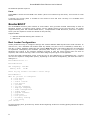
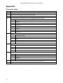
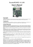
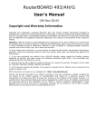
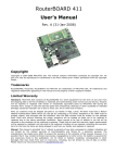
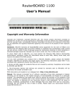
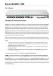
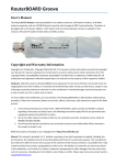
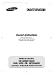
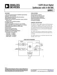
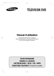
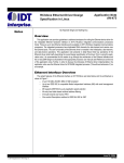
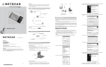
RouterBOARD 500r5 Series
User's Manual
Rev. Q (14-May-2007)
Copyright
Copyright © 2003-2007 MikroTikls SIA. This manual contains information protected by copyright law. No
part of it may be reproduced or transmitted in any form without prior written permission from the copyright
holder.
Trademarks
RouterBOARD, RouterOS, RouterBOOT and MikroTik are trademarks of MikroTikls SIA. All trademarks and
registered trademarks appearing in this manual are the property of their respective holders.
Limited Warranty
Hardware. MikroTikls SIA warrants all RouterBOARD 500 series equipment for the term of one year from
the shipping date to be free of defects in materials and workmanship under normal use and service. All parts
will be repaired or replaced with similar or functionally equivalent parts by MikroTikls SIA during the
warranty term, except in case the returned parts have mechanical, electrical or other accidental or intended
damages caused by improper use or due to wind, rain, fire or other acts of nature.
Parts (or systems) must be shipped pre-paid to our facility in Riga, Latvia. All items must have a Return
Material Authorization (RMA) which you can get by contacting us via email, telephone or fax. RMA must be
printed, signed, and enclosed with the shipment, also the RMA number must be written on the package
itself. Parts sent without following the proper procedure will be treated as those not to be repaired or
replaced due to the above mentioned conditions. Items proved to be free of defects in our lab will be
returned to the customer at the customer's expense. Those that do meet the warranty repair requirements
will be repaired or replaced, and returned to the customer's location at our expense, extending the warranty
term for the time the items are being shipped to and from our facility and replaced or repaired.
Manual. This manual is provided “as is” without a warranty of any kind, expressed or implied, including, but
not limited to, the implied warranty of merchantability and fitness for a particular purpose. The manufacturer
has made every effort to ensure the accuracy of the contents of this manual, however, it is possible that it
may contain technical inaccuracies, typographical or other errors. No liability is assumed for any inaccuracy
found in this publication, nor for direct or indirect, incidental, consequential or other damages that may
result from such an inaccuracy, including, but not limited to, loss of data or profits. Please report any
inaccuracies found to [email protected].
Caution
To avoid damage of the system, use the correct DC input voltage range.
RouterBOARD 500r5 Series User's Manual
Table of Contents
Copyright............................................................................................................................. ..........1
Trademarks................................................................................................................ ....................1
Limited Warranty........................................................................................... .................................1
Caution...................................................................................................................................... ....1
System Board View......................................................................................... ................................3
System Board Layout............................................................................................................. ..........3
Specifications....................................................................................................... ..........................4
Daughterboard Options............................................................................. ..............................4
Block Diagram.................................................................................................................... ....4
Hardware Guide........................................................................................................... ...................5
Memory and Storage Devices......................................................................... ..........................5
Onboard Memory.................................................................................... .......................5
Onboard NAND Storage Device.......................................................... ..............................5
CompactFlash Interface................................................................... ...............................5
Extension Slots....................................................................................... ...............................5
MiniPCI Slot.................................................................................... ..............................5
Input/Output Ports.............................................................................................................. ....5
LAN1 Port with PoE.................................................................................................. .......5
LAN2 Port.......................................................................................... ...........................5
LAN3 Port.......................................................................................... ...........................5
DB9 Serial Port............................................................................................. .................5
LEDs............................................................................................................................. ........6
Power LED....................................................................................... .............................6
User LED........................................................................................ ..............................6
MiniPCI LEDs................................................................................................ .................6
User's Guide....................................................................................................................... ............6
Assembling the Hardware........................................................................... .............................6
Grounding.................................................................................................... .........................6
Powering............................................................................................................ ...................6
Booting options.................................................................................................... ..................7
Onboard NAND Storage Device.......................................................... ..............................7
Internal Storage Device........................................................................ ..........................7
Booting from network.................................................................................... .................7
Operating System Support........................................................................................ ...............7
System Architecture................................................................................... ....................7
MikroTik RouterOS............................................................................. ............................7
Linux........................................................................................................................ ....8
RouterBOOT.......................................................................................................... .........................8
Boot Loader Configuration..................................................................................................... ...8
Configurable Options............................................................................... .......................9
Changing CPU Frequency..................................................................................... ....................9
Boot Loader Upgrading............................................................................................... .............9
Appendix................................................................................................................................. .....10
Connector Index................................................................................................ ...................10
Jumper Index......................................................................................................... ..............11
Button Index.......................................................................................................... ..............11
Ethernet Cables................................................................................................... .................11
Full Serial Null-modem (Console) Cable............................................................................... .....11
2
RouterBOARD 500r5 Series User's Manual
System Board View
Top view
Bottom view
System Board Layout
Note: on the other side of the board, there is only a MiniPCI connector, so no layout diagram shown.
3
RouterBOARD 500r5 Series User's Manual
Specifications
RouterBOARD 532
CPU
RouterBOARD 532A
MIPS32 4Kc based 400MHz embedded processor
Memory
32MB DDR onboard memory chip
Boot loader
64MB DDR onboard memory chip
RouterBOOT, 1Mbit Flash chip
128MB onboard NAND memory chip
CompactFlash type I/II slot (also supports IBM/Hitachi Microdrive)
Data storage
One IDT Korina 10/100 Mbit/s Fast Ethernet port supporting Auto-MDI/X
Two VIA VT6105 10/100 Mbit/s Fast Ethernet ports supporting Auto-MDI/X
Ethernet
MiniPCI slot
Two MiniPCI Type IIIA/IIIB slots
Serial port
One DB9 RS232C asynchronous serial port
LEDs
Power, 2 LED pairs for MiniPCI slots, 1 user LED
Watchdog
IDT internal SoC hardware watchdog timer
Speaker
Mini PC-Speaker
IEEE802.3af Power over Ethernet: 12V or 48V DC mode
Power jack 6..22V (with overvoltage protection) or 25..60V DC – jumper selectable
Power options
Dimensions
14.0 cm x 14.0 cm (5.51 in x 5.51 in)
Weight
140 g (4.9 oz)
Temperature
Operational: -20°C to +70°C (-4°F to 158°F)
Humidity
Operational: 70% relative humidity (non-condensing)
Power consumption 2-4W without extension cards, maximum – 24W (16.5W output to extension cards)
Daughterboard Options
Ethernet
MiniPCI slot
RouterBOARD 564
RouterBOARD 502
Six VIA VT6105 10/100 Mbit/s Fast
Ethernet ports supporting Auto-MDI/X
No Ethernet ports
Four MiniPCI Type IIIA/IIIB slots
Two MiniPCI Type IIIA/IIIB slots
Block Diagram
6..22/25..60V power jack
Power
Supply
12/48V PoE
Onboard RAM
Onboard Flash (NAND)
100BaseTX port 1
(with PoE in)
100BaseTX port 2
Ethernet
Controller
100BaseTX port 3
Ethernet
Controller
CPU
PCI
CF connector
Serial port
GPIO pins
User LED
Speaker
2 MiniPCI slots
Daughterboard
connector
4
RouterBOARD 500r5 Series User's Manual
Hardware Guide
Memory and Storage Devices
Onboard Memory
The boards are equipped with one 32MB DDR memory chip. RB532A build version has 64MB DDR memory
chip onboard.
Onboard NAND Storage Device
The boards are equipped with one 128MB NAND nonvolatile memory chip.
CompactFlash Interface
You can use any CompactFlash Type I or II cards, as well as IBM/Hitachi Microdrive hard drives. Warning!
The RouterBOARD 500 series boards do not support hot insert of CompactFlash/Microdrive
devices.
Extension Slots
MiniPCI Slot
MiniPCI Type IIIA slot has 3.3V only power signaling. This slot also accepts MiniPCI Type IIIB standard cards.
Supplied power for the extension cards (excluding CPU and onboard Ethernet ports):
+3.3V: 5A (16.5W)
Input/Output Ports
LAN1 Port with PoE
This Fast Ethernet port is recognized as first LAN interface in most OSs. It is fully compatible with
IEEE802.3af Power over Ethernet standard and passive PoE (non-standard). The board accepts either 12 or
48 V DC input voltage according to the configuration. To use standard PoE power option on this interface,
switch jumpers JP3 and JP4 to the 1-2 position. The PoE input can also be switched to 12V non-standard PoE
powering (switching JP3 and JP4 to the 2-3 position).
The RouterBOARD 51 power injector may be used to power the board with up to 100m (330 ft) long
Ethernet cable.
See Connector Index for pinout of the standard cable required for PoE. All cables made to EIA/TIA 568A/B
cable specifications will work correctly with PoE. Note that this port supports automatic cross/straight cable
correction (Auto MDI/X), so you can use either straight or cross-over cable for connecting to other network
devices.
LAN2 Port
This Fast Ethernet port is recognized as second LAN interface in most OSs. This port does not support Power
over Ethernet.
See Connector Index for pinout of the standard cable. Note that this port supports automatic
cross/straight cable correction (Auto MDI/X), so you can use either straight or cross-over cable for
connecting to other network devices.
LAN3 Port
This Fast Ethernet port is recognized as third LAN interface in most OSs. This port does not support Power
over Ethernet.
See Connector Index for pinout of the standard cable. Note that this port supports automatic
cross/straight cable correction (Auto MDI/X), so you can use either straight or cross-over cable for
connecting to other network devices.
DB9 Serial Port
The RS232C standard male DB9 asynchronous serial port may be used for initial configuration, or for
5
RouterBOARD 500r5 Series User's Manual
attaching a modem or any other RS232 serial device. TxD (pin 3) of this port has -12V DC power when idle.
LEDs
Power LED
LED is on when the board is powered
User LED
User LED may be programmed at user's option. See RouterBOARD 500 SDK for more details.
MiniPCI LEDs
2 pairs of MiniPCI LEDs are connected to MiniPCI slots (two LEDs per slot) according to standards.
User's Guide
Assembling the Hardware
First to use the board:
● In most cases you do not need to use any additional boot devices, as you can boot the RouterBOARD
from the onboard NAND memory. You can also install a CompactFlash module or Microdrive hard drive,
which you can use as an alternative boot device or an additional storage medium. Warning! The
RouterBOARD 500 series does not support hot insert of CompactFlash/Microdrive devices.
● Configure jumpers. The board should have 2 jumpers already set in some positions. See the following
section on how to choose the appropriate setting. Also the Jumper Index chapter of this manual
describes all possible jumper positions
● Insert MiniPCI cards on the board itself, and on the Daughterboard if you have one
● Install the board in a case. Connect and secure the Daughterboard on top of it if you have one
● Connect other peripherals and cables
You can also order a pre-assembled system with RouterBOARD and extension cards of your choice already
installed in a case.
Grounding
Use pan head machine screws of correct diameter; internal star lock washers are recommended. Make sure
all mounting holes on the board are connected (if you do not use MikroTik's standard mounting cases, which
provide the connection by design) and provide a proper grounding from them to the grounding terminal
(resistance of this connection must be less or equal to 1 Ω). As an alternative, we can recommend using
industrial made EMI suppressor or ferrite bead on UTP cable connected to the Ethernet port 1 on the board.
Place it as close to the Ethernet connector as possible. At least two windings are recommended if ferrite
bead is used. In case STP cable is used to connect the board, EMI suppressor/bead is not necessary but
proper connection of the cable's shield to the grounding terminal must be ensured.
Powering
Power options:
● J13 power jack:
6..22V or 25..60V DC
● IEEE802.3af Power over Ethernet (PoE) on the first Ethernet port:
48V DC
12V DC non-standard PoE powering support
RouterBOARD 500 series boards are equipped with a reliable 24W onboard power supply that accepts a wide
range of input voltage from either the power jack (5.5mm outside and 2mm inside diameter, female, pin
positive plug) or the first Ethernet port. Both power inputs are always active. JP3 and JP4 choose input
voltage (1-2 for 25..60V DC, 2-3 for 6..22V DC). Note that because of wire resistance, PoE requires higher
voltage (it is recommended to use 11V minimum). The low voltage mode has overvoltage protection circuit,
so you will not damage the board if jumpers are set incorrectly, but the power is within 6..60 V DC range.
RouterBOARD 500 series boards are compliant with IEEE802.3af Power over Ethernet standard and accept
6
RouterBOARD 500r5 Series User's Manual
48V powering over up to 100m (330 ft) long Ethernet cable connected to the first Ethernet port (J6). The
board also accepts 12V DC (or any other within the 11..22V range) non-standard PoE input voltage (see
note above on how to use it).
Booting options
First, RouterBOOT loader is started. It displays some useful information on the onboard RS232C
asynchronous serial port, which is set to 115200bit/s, 8 data bits, 1 stop bit, no parity, hardware (RTS/CTS)
flow control by default. The loader may be configured to boot the system from the onboard NAND module,
an internal storage device, or from Ethernet network. See the respective section of this manual for how to
configure booting sequence and other boot loader parameters.
Onboard NAND Storage Device
The RouterBOARD may be started from the onboard NAND storage chip. As there is no partition table on the
device, the boot loader assumes the first 4MiB form a YAFFS filesystem, and executes the file called “kernel”
stored in the root directory on that partition. It is possible to partition the rest of the medium by patching
the kernel source.
Internal Storage Device
The RouterBOARD may be started from a CompactFlash module or a Microdrive hard drive. At least two
partitions must exist on the device, first of which being the ELF image the board is to be booted from
(normally, it is a Linux kernel, appended with the kernparm ELF section that specifies the root partition
name and, optionally, other kernel parameters of your choice).
Booting from network
Network boot works similarly to PXE or EtherBoot protocol, and allows you to boot the RouterBOARD 500
series computer from an executable image stored on a TFTP server. It uses BOOTP or DHCP (configurable in
boot loader) protocol to get a valid IP address, and TFTP protocol to download an executable (ELF) kernel
image combined with the initial RAM disk (inserted as an ELF section) to boot from (the server's IP address
and the image name must be sent by the BOOTP/DHCP server).
To boot the RouterBOARD computer from Ethernet network you need the following:
● An ELF kernel image for the loader to boot from (you can embed the kernel parameters and initrd
image as ELF sections called kernparm and initrd respectively)
● A TFTP server which to download the image from
● A BOOTP/DHCP server (may be installed on the same machine as the TFTP server) to give an IP
address, TFTP server address and boot image name
See the RouterBOOT section on how to configure loader to boot from network.
Note that you must connect the RouterBOARD you want to boot, and the BOOTP/DHCP and TFTP servers to
the same broadcast domain (i.e., there must not be any routers between them).
Operating System Support
System Architecture
RouterBOARD 500 series embedded boards are fully compatible with the standard MIPS32 architecture with
PCI bus.
CPU. RouterBOARD 500 series has MIPS32 little-endian based embedded processor using MIPS 4Kc CPU
core. It is fully binary-compatible with all software developed for MIPS32 little-endian (mipsel) instruction
set architecture. The MIPS 4Kc core includes TLB Memory Management Unit and does not include Float Point
Unit (so it is optimized for integer operations).
Ethernet. RouterBOARD 500 series has three onboard Ethernet ports. The first port is controlled by IDT
Korina MAC embedded in the CPU and ADMtek PHY chip. The second and the third Ethernet ports are
controlled by VIA VT6105 integrated MAC/PHY chips.
The RouterBOARD 500 SDK describes programming LED, Watchdog, JP1 jumper and S1 button.
MikroTik RouterOS
MikroTik RouterOS (special RouterBOARD 500 edition, starting from version 2.9) is fully compatible with
RouterBOARD 500 series embedded boards.
7
RouterBOARD 500r5 Series User's Manual
No additional patches required.
Linux
RouterBOOT is tested to boot DELO Linux loader (other Linux loaders may also work). Linux kernel 2.4 was
tested.
A special Linux kernel patch is needed for the board to boot and work correctly. It is available from
www.routerboard.com
RouterBOOT
The RouterBOOT firmware (also referred as “boot loader” here) provides minimal functionality to boot an
Operating System. It supports serial console via the onboard serial port at the boot time. The loader
supports booting from the onboard NAND device, CompactFlash or IBM Microdrive, and from a network
server (see the respective section for details on this protocol).
Supported OSs:
● MikroTik RouterOS starting with version 2.9
● GNU/Linux
Boot Loader Configuration
Loader parameters may be configured through the onboard RS232C DB9 asynchronous serial interface. To
connect to it, use a standard null-modem cable. By default, the port is set to 115200bit/s, 8 data bits, 1
stop bit, no parity, hardware (RTS/CTS) flow control. Note that some null-modem cables do not implement
or implement incompletely the hardware (RTS/CTS) flow control, so it is suggested to try to disable
hardware flow control in the terminal emulation program in case the serial console does not work as
expected, and if it does not help, make a new cable using the pinout given in the Appendix.
To enter the loader configuration screen, press any key (or only [Delete] key (or [Backspace] key – see the
note for the respective configurable option), depending on the actual configuration) just after the loader is
asking for it:
RouterBOOT booter 2.7
RouterBoard 532
CPU frequency: 399 MHz
Memory size: 32 MB
Press any key within 2 seconds to enter setup.
RouterBOOT-2.7
What do you want to configure?
d - boot delay
k - boot key
s - serial console
o - boot device
u - cpu mode
f - try cpu frequency
c - keep cpu frequency
r - reset configuration
e - format nand
g - upgrade firmware
i - board info
p - boot protocol
t - do memory testing
x - exit setup
your choice:
To select a menu point, press the key written at the beginning of this line. Pressing [Enter] selects the option
marked with '*'.
8
RouterBOARD 500r5 Series User's Manual
Configurable Options
boot delay – how much time to wait for a key stroke while booting (1..10 seconds; 1 second by default).
boot key – which key will cause the loader to enter configuration mode during boot delay (any key |
<Delete> key only; any key by default). Note that in some serial terminal programs, it is impossible to use
the [Delete] key to enter the setup – in this case it might be possible to do this with the [Backspace] key.
serial console – to configure initial serial console bitrate (1200 | 2400 | 4800 | 9600 | 19200 | 38400 |
57600 | 115200; 115200 bps by default).
boot device – initial boot device (Etherboot | boot from NAND | boot from CF | boot Ethernet once, then
NAND | boot Ethernet once, then CF; boot from NAND by default). You can also select boot chosen
device option to boot from the device selected immediately, without saving the setting.
cpu mode – whether to enter CPU suspend mode on HTL instruction (power save | regular; power save by
default). Most OSs use HLT instruction during CPU idle cycle. When CPU is in suspend mode, it consumes
less power, but in low-temperature conditions (below 0°C) it is recommended to choose regular mode, so
that overall system temperature would be higher.
try cpu frequency – try this CPU frequency on the next power cycle (199MHz | 266MHz | 333MHz |
399MHz; 399MHz by default).
keep cpu frequency – permanently set the current CPU frequency (not the one set, but the one actually
active).
reset configuration – whether to reset all the boot loader settings to their respective default values (yes |
no; no by default).
format nand – perform a low-level NAND format. During this operation, all previously marked bad sectors
are retested to find out if they are faulty indeed.
upgrade firmware – receive a new boot loader image using XModem protocol over serial line or using
DHCP/BOOTP and TFTP protocols through the Ethernet network (upgrade firmware over ethernet | upgrade
firmware over serial port).
board info – prints the serial number, boot loader version, CPU frequency, memory size and MAC addresses
of the onboard Ethernet ports
boot protocol – network booting protocol (bootp protocol | dhcp protocol; bootp protocol by default).
do memory testing – performs a full memory test.
Changing CPU Frequency
By default, the RouterBOARD 500 series boards are equipped with the processors, tested at 400MHz clock
frequency, but you can select a lower frequency (200, 266 or 333) if the system is not cooled sufficiently and
the heat, dissipated by the CPU, causes the system to overheat and work unstable. The bootloader is made
so that you must first try a different frequency before it could be set permanently, and if you do not apply a
frequency permanently, it would fall back to the previous setting on the next power cycle.
Boot Loader Upgrading
The boot loader is needed to initialize all the hardware and boot the system up. Newer loader versions might
have support for more hardware, so it's generally a good idea to upgrade the loader once a newer version is
available. You can upgrade the loader through the onboard serial port using XModem protocol (programs
available for all major OSs). For example, you can use HyperTerminal for Windows or Minicom for Linux to
upload the boot loader. Alternatively if you have a DHCP/BOOTP and TFTP servers available, you can specify
the loader image as a boot image and choose the bios upgrade over ethernet option in the boot loader
configuration menu. The loader will get the image from the TFTP server and upgrade itself. The most current
loader image is available for download on www.routerboard.com.
The boot loader upgrading is supported also from MikroTik RouterOS. The procedure is described in the
MikroTik RouterOS manual.
Should the upgrade fail, you may try loading secondary boot loader, by turning the board on while the S1
button is pressed. If that works, you should try upgrading the loader again.
9
RouterBOARD 500r5 Series User's Manual
Appendix
Connector Index
J2
CompactFlash type I/II (with Microdrive support) slot
J3
MiniPCI Type type IIIA/B connector 1 (top side)
J4
MiniPCI Type type IIIA/B connector 2 (bottom side)
J5
RouterBOARD 500 daughterboard connector (proprietary pinout)
J6
RJ45 Fast Ethernet 100Base-TX port 1 with IEEE802.3af PoE extension
1 Data TX+
2 Data TX3 Data RX+
4 PoE power +
5 PoE power +
6 Data RX7 PoE power 8 PoE power -
J8
RS232C male DB9 serial port
2 RxD (Receive Data)
3 TxD (Transmit Data)
5 GND
7 RTS (Request to Send)
8 CTS (Clear to Send)
J9
RJ45 Fast Ethernet 100Base-TX port 2
1 Data TX+
2 Data TX3 Data RX+
6 Data RX-
J10
RJ45 Fast Ethernet 100Base-TX port 3
1 Data TX+
2 Data TX3 Data RX+
6 Data RX-
J13
Power jack (6..22V or 25..60V DC, positive contact is the central pin)
JP8
External speaker connector
10
RouterBOARD 500r5 Series User's Manual
Jumper Index
JP1
User-defined jumper (GPIO3 / CTS signal – only useful when serial port is not used)
JP3
JP4
Input voltage select
1-2
48V mode (25..60V DC)
2-3
12V mode (6..22V DC), with overvoltage protection
Button Index
S1
During the boot loader initialization, loads the secondary boot loader (in case the primary
loader is damaged). User-defined button (GPIO1 / RxD signal – only useful when serial port is
not used)
Ethernet Cables
RJ45
Pin
Color
Function RJ45 pin for Straight cable RJ45 pin for Crossover cable
(MDI, EIA/TIA568A)
(MDI-X, EIA/TIA568B)
1
Green
TX+ Data
1
3
2
Green/White
TX- Data
2
6
3
Orange
RX+ Data
3
1
4
Blue
-
4
4
5
Blue/White
-
5
5
6
2
6
Orange/White RX- Data
7
Brown
-
7
7
8
Brown/White
-
8
8
Full Serial Null-modem (Console) Cable
DB9f Function DB9f DB25f
1+6
CD+DSR
4
20
2
RxD
3
2
3
TxD
2
3
4
DTR
1+6
6+8
5
GND
5
7
7
RTS
8
5
8
CTS
7
4
11