1
ViewSonic
®
CD4620
LCD Commercial Display
IMPORTANT: Please read this User Guide to obtain important
information on installing and using your product in a safe manner, as
well as registering your product for future service. Warranty information
contained in this User Guide will describe your limited coverage from
ViewSonic Corporation, which is also found on our web site at http://
www.viewsonic.com in English, or in specific languages using the
Regional selection box in the upper right corner of our website.
“Antes de operar su equipo lea cuidadosamente las instrucciones en
este manual”
Model No. : VS11915
Contents
Safety Precautions ................................................................................................ 5
Package Contents ................................................................................................. 6
Parts Name and Functions ................................................................................... 7
Control Panel ......................................................................................................................7
Terminal Panel. ...................................................................................................................8
Wireless Remote Control....................................................................................................9
Operating Range for the Remote Control .........................................................................10
Handling the remote control..............................................................................................10
Setup Procedure ................................................................................................. 11
How to Mount and Attach Options to the LCD Monitor. .................................. 13
Connections ........................................................................................................ 15
Wiring Diagram .................................................................................................................15
Connecting a Personal Computer.....................................................................................16
Connecting with Digital Interface Equipment ....................................................................17
Connecting a DVD Player with component out.................................................................18
Connecting to a Stereo Amplifier ......................................................................................19
Basic Operation................................................................................................... 20
Power ON and OFF Modes ..............................................................................................20
Power Indicator. ................................................................................................................21
Using Power Management ...............................................................................................21
Selecting a video source...................................................................................................21
Picture Size.......................................................................................................................21
Picture Mode.....................................................................................................................22
Audio Source Switching....................................................................................................22
Information OSD ...............................................................................................................22
OSD (On-Screen-Display) Controls .................................................................. 23
PICTURE ..........................................................................................................................24
SCREEN...........................................................................................................................25
AUDIO ..............................................................................................................................26
PICTURE IN PICTURE.....................................................................................................27
CONFIGURATION 1.........................................................................................................28
CONFIGURATION 2.........................................................................................................29
ADVANCED OPTION .......................................................................................................30
ViewSonic CD4620
Controlling the LCD monitor via RS-232C Remote Control ........................... 34
Appendix: Installing and removing stands....................................................... 35
Features ............................................................................................................... 36
Troubleshooting .................................................................................................. 37
Specifications...................................................................................................... 38
Customer Support............................................................................................... 39
Limited Warranty ................................................................................................. 40
Mexico Limited Warranty.................................................................................... 42
ViewSonic CD4620
Compliance Information
For U.S.A.
This equipment has been tested and found to comply with the limits for a Class A digital
device, pursuant to Part 15 of the FCC Rules. These limits are designed to provide reasonable
protection against harmful interference when the equipment is operated in a commercial
environment. this equipment generates, uses, and can radiate radio frequency energy and, if not
installed and used in accordance with the instruction manual, may cause harmful interference
to radio communications. operation of this equipment in a residential area is likely to cause
harmful interference in which case the user will be required to correct the interference at his
own expense.
Warning: You are cautioned that changes or modifications not expressly approved by the
party responsible for compliance could void your authority to operate the equipment.
For Canada
This Class A digital apparatus complies with Canadian ICES-003.
Cet appareil numérique de la classe A est conforme à la norme NMB-003 du Canada.
CE Conformity for European Countries
The device complies with the requirements of the EEC directive 89/336/EEC,
2004/108/EC as amended by 92/31/EEC and 93/68/EEC Art.5 with regard to
"Electromagnetic compatibility", and 73/23/EEC as amended by 93/68/EEC
Art.13 with regard to "Safety."
Warning: This is a class A product. in a domestic environment this product may cause radio
interference in which case the user may be required to take adequate measures
Following information is only for EU-member states:
The mark shown to the right is in compliance with the Waste Electrical and
Electronic Equipment Directive 2002/96/EC (WEEE).
The mark indicates the requirement NOT to dispose the equipment as unsorted
municipal waste, but use the return and collection systems according to local law.
ViewSonic CD4620
1
Important Safety Instructions
1. Read these instructions completely before using the equipment.
2. Keep these instructions in a safe place.
3. Heed all warnings.
4. Follow all instructions.
5. Do not use this equipment near water. Warning: To reduce the risk of fire or
electric shock, do not expose this apparatus to rain or moisture.
6. Clean with a soft, dry cloth. If further cleaning is required, see “Cleaning the
Display” in this guide for further instructions.
7. Do not block any ventilation openings. Install the equipment in accordance with
the manufacturer’s instructions.
8. Do not install near any heat sources such as radiators, heat registers, stoves, or
other devices (including amplifiers) that produce heat.
9. Do not attempt to circumvent the safety provisions of the polarized or groundingtype plug. A polarized plug has two blades with one wider than the other. A
grounding type plug has two blades and a third grounding prong. The wide blade
and the third prong are provided for your safety. If the plug does not fit into your
outlet, consult an electrician for replacement of the outlet.
10. Protect the power cord from being tread upon or pinched, particularly at the plug,
and the point where if emerges from the equipment. Be sure that the power outlet
is located near the equipment so that it is easily accessible.
11. Only use attachments/accessories specified by the manufacturer.
12. Use only with the cart, stand, tripod, bracket, or table specified by
the manufacturer, or sold with the equipment. When a cart is used,
use caution when moving the cart/equipment combination to avoid
injury from tipping over.
13. Unplug this equipment when it will be unused for long periods of time.
14. Refer all servicing to qualified service personnel. Service is required when the unit
has been damaged in any way, such as: if the power-supply cord or plug is
damaged, if liquid is spilled onto or objects fall into the unit, if the unit is exposed
to rain or moisture, or if the unit does not operate normally or has been dropped.
ViewSonic CD4620
2
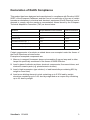
Declaration of RoHS Compliance
This product has been designed and manufactured in compliance with Directive 2002/
95/EC of the European Parliament and the Council on restriction of the use of certain
hazardous substances in electrical and electronic equipment (RoHS Directive) and is
deemed to comply with the maximum concentration values issued by the European
Technical Adaptation Committee (TAC) as shown below:
Substance
Proposed Maximum Concentration
Actual Concentration
Lead (Pb)
0.1%
< 0.1%
Mercury (Hg)
0.1%
< 0.1%
Cadmium (Cd)
0.01%
< 0.01%
Hexavalent Chromium (Cr6+)
0.1%
< 0.1%
Polybrominated biphenyls (PBB)
0.1%
< 0.1%
Polybrominated diphenyl ethers (PBDE)
0.1%
< 0.1%
Certain components of products as stated above are exempted under the Annex of
the RoHS Directives as noted below:
Examples of exempted components are:
1. Mercury in compact fluorescent lamps not exceeding 5 mg per lamp and in other
lamps not specifically mentioned in the Annex of RoHS Directive.
2. Lead in glass of cathode ray tubes, electronic components, fluorescent tubes, and
electronic ceramic parts (e.g. piezoelectronic devices).
3. Lead in high temperature type solders (i.e. lead-based alloys containing 85% by
weight or more lead).
4. Lead as an allotting element in steel containing up to 0.35% lead by weight,
aluminium containing up to 0.4% lead by weight and as a cooper alloy containing
up to 4% lead by weight.
ViewSonic CD4620
3
Copyright Information
Copyright © ViewSonic® Corporation, 2007. All rights reserved.
Macintosh and Power Macintosh are registered trademarks of Apple Computer, Inc.
Microsoft, Windows, Windows NT, and the Windows logo are registered trademarks of
Microsoft Corporation in the United States and other countries.
ViewSonic, the three birds logo, OnView, ViewMatch, and ViewMeter are registered
trademarks of ViewSonic Corporation.
VESA is a registered trademark of the Video Electronics Standards Association.
DPMS and DDC are trademarks of VESA.
ENERGY STAR® is a registered trademark of the U.S. Environmental Protection Agency
(EPA).
As an ENERGY STAR® partner, ViewSonic Corporation has determined that this product
meets the ENERGY STAR® guidelines for energy efficiency.
Disclaimer: ViewSonic Corporation shall not be liable for technical or editorial errors or
omissions contained herein; nor for incidental or consequential damages resulting
from furnishing this material, or the performance or use of this product.
In the interest of continuing product improvement, ViewSonic Corporation reserves
the right to change product specifications without notice. Information in this document
may change without notice.
No part of this document may be copied, reproduced, or transmitted by any means, for
any purpose without prior written permission from ViewSonic Corporation.
Product Registration
To meet your future needs, and to receive any additional product information as it
becomes available, please register your product on the Internet at:
www.viewsonic.com. The ViewSonic Wizard CD-ROM also provides an opportunity
for you to print the registration form, which you may mail or fax to ViewSonic.
For Your Records
Product Name:
Model Number:
Document Number:
Serial Number:
Purchase Date:
CD4620
ViewSonic 46” LCD Commercial Display
VS11915
CD4620-1_UG_ENG Rev. 1B 11-14-07
_______________________________
_______________________________
Product disposal at end of product life
The lamp in this product contains mercury. Please dispose of in accordance with
local, state or federal laws.
ViewSonic is concerned about the preservation of our environment. Please dispose of
this product properly at the end of its useful life. For the recycling information, please
refer to our website:
1. USA: www.viewsonic.com/pdf/RecyclePlus.pdf
2. Europe: www.viewsoniceurope.com
3. Taiwan: recycle.epa.gov.tw
ViewSonic CD4620
4
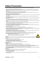
Safety Precautions
FOR OPTIMUM PERFORMANCE,
PLEASE NOTE THE FOLLOWING WHEN SETTING UP AND USING THE LCD COLOR MONITOR:
y DO NOT REMOVE MONITOR BACK COVER. There are no user serviceable parts inside and opening or
removing covers may expose you to dangerous shock hazards or other risks. Refer all servicing to qualified service
personnel.
y Do not spill any liquids into the cabinet or use your monitor near water.
y Do not insert objects of any kind into the cabinet slots, as they may touch dangerous voltage points, which can be
harmful or fatal or may cause electric shock, fire or equipment failure.
y Do not place any heavy objects on the power cord.
Damage to the cord may cause shock or fire.
y Do not place this product on a sloping or unstable cart, stand or table, as the monitor may fall, causing serious damage
to the monitor.
y When operating the LCD monitor with an AC 100-120V power supply in North America, use a power supply cord
provided with this monitor.
y When operating the LCD monitor with an AC 220-240V power supply in Europe, use a power supply cord provided with
this monitor.
y In UK, use a BS-approved power cord with molded plug having a black (10A) fuse installed for use with this monitor.
If a power cord is not supplied with this monitor, please contact your supplier.
y When operating the LCD monitor with a 220-240V AC power supply in Australia, use the power cord provided with this
monitor.
If a power cord is not supplied with this monitor, please contact your supplier.
y For all othercase, use a power cord that matches the AC voltage of the power outlet and has been approved by and
complies with the safety standard of your particular country.
y Do not place any objects onto the monitor and do not use the monitor outdoors.
y The inside of the fluorescent tube located within the LCD monitor contains mercury. Please follow the laws or rules of
your municipality to dispose of the tube properly.
y Do not bend power cord.
y Do not use monitor in high temperature, humid, dusty, or oily areas.
y If monitor or glass is broken, do not come in contact with the liquid crystal and handle with care.
y Allow adequate ventilation around the monitor, so that heat can properly dissipate. Do not block ventilated openings or
place the monitor near a radiator or other heat sources.
Do not put anything on top of the monitor.
y The power cable connector is the primary means of detaching the system from the power supply. The monitor should
be installed close to a power outlet, which is easily accessible.
y Handle with care when transporting. Save packaging for transporting.
y Please clean the holes of back cabinet to reject dirt and dust at least once a year because of set reliability.
y If using the cooling fan continuously, it’s recommended to wipe holes a minimum of once a month.
y When installing the remote control batteries;
Align the batteries according to the (+) and (-) indications inside the case.
- Align the (-) indication of the battery first inside the case.
CAUTION:
Immediately unplug your monitor from the wall outlet and refer servicing to qualified service personnel under the following
conditions:
y When the power supply cord or plug is damaged.
y If liquid has been spilled, or objects have fallen into the monitor.
y If the monitor has been exposed to rain or water.
y If the monitor has been dropped or the cabinet damaged.
y If the monitor does not operate normally by following operating instructions.
Recommended Use
CAUTION:
y For optimum performance, allow 20 minutes for warm-up.
y Rest your eyes periodically by focusing on an object at least 5 feet away. Blink often.
y Position the monitor at a 90° angle to windows and other light sources to minimize glare and reflections.
y Clean the LCD monitor surface with a lint-free, nonabrasive cloth. Avoid using any cleaning solution or glass cleaner!
y Adjust the monitor’s brightness, contrast and sharpness controls to enhance readability.
y Avoid displaying fixed patterns on the monitor for long periods of time to avoid image persistence (after image effects).
y Get regular eye checkups.
Ergonomics
To realize the maximum ergonomic benefits, we recommend the following:
y Use the preset Size and Position controls with standard signals.
y Use the preset Color Setting.
y Use non-interlaced signals.
y Do not use primary color blue on a dark background, as it is difficult to see and may produce eye fatigue due to
insufficient contrast.
ViewSonic CD4620
5
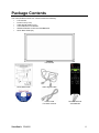
Package Contents
Your new CD4620 monitor box* should contain the following:
y
LCD monitor
y
Power Cord (1.8 m)
y
Video Signal Cable (1.8 m)
y
User’s Manual in CD Wizard
y
Wireless Remote Control and AAA Batteries
y
Quick Start Guide (A4)
LCD monitor
Quick Start Guide
Video Signal Cable
CD Wizard
Power cored
For North America
ViewSonic CD4620
Remote control &
AAA batteries
6
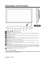
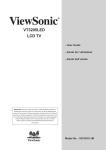
Parts Name and Functions
Control Panel
Button Location
POWER button ( ) - Switches the power on/off.
MUTE button - Switches the audio mute ON/OFF.
INPUT button - Acts as SET button with OSD menu.(Toggle switches between [RGB1], [RGB2], [RGB3], [RGB4],
[DVD/HD], [VIDEO<S>] and [VIDEO] .)
PLUS (+) button - Acts as (+) button to increase the adjustment with OSD menu. Increase the audio output level
when the OSD menu is turned off.
MINUS (-) button - Acts as (-) button to decrease the adjustment with OSD menu. Decreases the audio output level
when the OSD menu is turned off.
UP (S) button - Activates the OSD menu when the OSD menu is turned-off. Acts as S button to move the
highlighted area up to select the adjustment with OSD menu.
DOWN (T) button - Activates the OSD menu when the OSD menu is turned-off. Acts as T button to move the
highlighted area down to select the adjustment with OSD menu.
EXIT button - Activates the OSD menu when the OSD menu is turned-off. Acts as EXIT button to move to previous
menu with OSD menu.
Remote control sensor and Power indicator - Receives the signal from the remote control (when using the
wireless remote control). Glows green when the LCD monitor is in active and glows red when the LCD is in POWER OFF
mode. When the LCD is in power save mode, it will glow both green and red. When SCHEDULE is enabled, it will blink
green and glow red. In the case of where a failure is detected, it will blink red.
Main Power Switch - On/Off Switch to turn main power on/off.
NOTE: Control Key Lock Mode
This control completely locks out access to all Control Key functions. To activate the control key lock function, press both
of “S” and “T” and hold down simultaneously for more than 3 seconds. To resume back to user mode, press both of “S”
and “T” and hold simultaneously for three (3) seconds.
ViewSonic CD4620
7
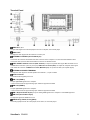
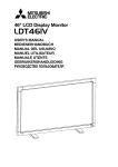
Terminal Panel
AUDIO IN 1, 2, 3
To input audio signal from external equipment such as a computer, VCR or DVD player.
AUDIO OUT
To output the audio signal from the AUDIO IN 1,2 and 3 jack.
EXTERNAL CONTROL (mini D-Sub 9 pin)
Connect the IN connector with the RS-232C OUT connector of the computer or a multi-connected CD4620 monitor.
Connect the OUT connector with the RS-232C IN connector of CD4620 monitor.
VIDEO IN/OUT VIDEO IN connector (BNC and RCA): To input a composite video signal. BNC and RCA are not
available at the same time. (Use only one input). VIDEO OUT connector (BNC): To output the composite video signal
from VIDEO IN connector. S-VIDEO IN connector (MINI DIN 4 pin): To input the S-video (Y/C separate signal).
EXTERNAL SPEAKER TERMINAL
To output the audio signal for external speakers from AUDIO 1, 2, 3 jack or HDMI.
AC IN connector
Connects with the supplied power cord.
RGB 1 IN (HDMI 1)
To input digital RGB signals from a computer.
* This connector does not support analog input. AUDIO is supported via HDMI.
RGB 2 IN (HDMI 2)
To input digital RGB signals from a computer.
* This connector does not support analog input. AUDIO is supported via HDMI.
RGB 3 IN (mini D-Sub 15 pin) To input a analog RGB signals from a computer or other RGB equipment.
RGB OUT (mini D-Sub 15 pin)
To output the signal from RGB 3 IN or 4 IN.
DVD/HD IN [Y, Pb/Cb, Pr/Cr] (BNC)
Connecting equipment such as a DVD player, HDTV device, or Laser disc player.
ViewSonic CD4620
8
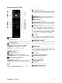
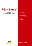
Wireless Remote Control
LEFT button decrease
Acts as (W) button to decrease the adjustment with OSD
menu. Small screen which adjusted “PIP” mode moves
left.
ENTER button Acts as SET button with OSD menu.
MENU button To switch the menu mode on/off.
DISPLAY button
To switch the information OSD on/off.
INPUT button Selects from input signal, [RGB1],
[RGB2], [RGB3], [DVD/HD], [VIDEO<S>] and [VIDEO].
AUDIO INPUT button Press to change the audio
source for each video source. The audio source is
changed from [AUDIO1] to [AUDIO2], [AUDIO3] and
[HDMI] in order. Note that you cannot select the audio
source for [VIDEO<S>] or [VIDEO]. [HDMI] is selectable
only when the video source is [RGB 1] and [RGB 2].
UP button
Acts as S button to move the highlighted area up to
POWER button
Switches the power on/off.
* If LED Power Indicator on the monitor is not glowing,
then no controls will work.
PICTURE MODE buttonSelects from picture mode,
[HIGHBRIGHT], [STANDARD], [sRGB], [CINEMA].
HIGHBRIGHT: for moving image such as Video
select the adjustment with OSD menu. Small screen
which adjusted “PIP” mode moves up.
RIGHT button increase
Acts as (X) button to increase the adjustment with OSD
menu. Small screen which adjusted “PIP” mode moves
right.
DOWN button
STANDARD: for images (Factory setting)
Acts as T button to move the highlighted area down to
sRGB: for text based images
select the adjustment with OSD menu. Small screen
CINEMA: for movies.
which adjusted “PIP” mode moves down.
SCREEN SAVER button
GAMMA button: To switch the Gamma setting.
BRIGHTNESS button: To switch the brightness setting.
PIP (Picture In Picture) button
ON/OFF button: PIP-ON/OFF.
INPUT button: Select the “picture in picture” input signal.
CHANGE button: Replaces to the main picture and sub
pic-ture.
Note:
The “PIP” and “POP” modes do not function when the
screen size is “CUSTOM” or “REAL”.
ViewSonic CD4620
EXIT button
Turn to previous menu with OSD menu.
VOLUME + button decrease
Increase the audio output level.
AUTO SETUP button
To enter the auto setup menu.
MUTE button
To switch the mute function on/off.
VOLUME - button increase
Decrease the audio output level.
9
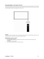
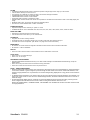
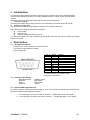
Operating Range for the Remote Control
Point the top of the remote control toward the LCD monitor's remote sensor during button operation. Use the remote
control within a distance of about 7 m/23 ft. from the front of the LCD monitor's remote control sensor and at a horizontal
and vertical angle of within 30° within a distance of about 3 m/10 ft.
CAUTION:
Important, the remote control system may not function when direct sunlight or strong illumination strikes the remote
control sensor of the LCD monitor, or when there is an object in the path.
Handling the remote control
7
7
7
7
Do not subject to strong shock.
Do not allow water or other liquid to splash the remote control. If the remote control gets wet, wipe it dry
immediately.
Avoid exposure to heat and steam.
Other than to install the batteries, do not open the remote.
ViewSonic CD4620
10
Setup Procedure
1. Determine the installation location
CAUTION: DO NOT ATTEMPT TO INSTALL THE LCD MONITOR BY YOURSELF. Installing your LCD display must be
done by a qualified technician. Contact your dealer for more information.
CAUTION: MOVING OR INSTALLING THE LCD MONITOR MUST BE DONE BY TWO OR MORE PEOPLE.Failure to
follow this caution may result in injury if the LCD monitor falls.
CAUTION: Do not mount or operate the display upside down, face up, or face down.
CAUTION: Do not install the LCD monitor where it will be exposed to direct sunlight, as this will result in display defects.
CAUTION: This LCD has a temperature sensor and cooling fan. If the LCD becomes too hot, the cooling fan will turn on
automatically. If the LCD becomes overheated and the cooling fan is running, the “Caution” menu will appear. If the
“Caution” menu appears, discontinue use and allow the unit to cool. When the LCD monitor is used in an enclosure or
with protection on LCD surface, please check the inside temperature of monitor by “HEAT STATUS”. The temperature is
too hot than normal condition, please set “cooling fan” to ON on SCREEN SAVER function.
IMPORTANT:
Lay the protective sheet, which was wrapped around the LCD monitor when it was packaged, beneath the LCD monitor
so as not to scratch the panel.
2. Install the remote control batteries
The remote control is powered by 1.5V AAA batteries. To install or replace batteries:
1. Press and slide to open the cover.
2. Align the batteries according to the (+) and (–) indications inside the case.
3. Replace the cover.
CAUTION:
Incorrect use of batteries can result in leaks or bursting. Be careful especially about the following points.
y Place “AAA” batteries matching the + and - signs on each battery to the + and - signs of the battery compartment.
y Do not mix battery types.
y Do not combine new batteries with used ones. It causes shorter battery life or leakage of batteries.
y Remove dead batteries immediately to prevent battery liquid from leaking into the battery compartment. Don't touch
exposed battery acid, it cause damage to your skin.
NOTE:
If you do not intend to use the Remote Control for a long period, remove the batteries.
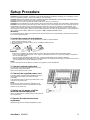
3. Connect external equipment
To protect the connected equipment, turn off the main
power before making connections.
Refer to your equipment user manual.
4. Connect the supplied power cord
The power outlet socket should be installated as near to
the equipment as possible, and should be easily
accessible.
Fully insert the prongs into the power outlet socket. Loose
connection may cause noise.
NOTE:
Please refer to “Safety Precautions, Maintenance &
Recommended Use” section of this manual for proper
selection of AC power cord.
5. Switch on the power of all the
attached external equipment
When connected with a computer, switch on the power of
the computer first.
6. Operate the attached external
equipment
Display the signal on the external equipment you wish.
ViewSonic CD4620
11
7. Adjust the sound
Make adjustments lowering or raising the volume as required.
8. Adjust the screen
Make adjustments to the display position or settings if required.
9. Adjust the image
Make adjustments to brightness or contrast if required.
10. Recommended Adjustment
To reduce the risk of “image persistence”, please adjust the following items based on the application being used.
“POWER SAVE”, “SCREEN SAVER”, “DATE AND TIME”, “SCHEDULE”.
11. When CD4620 is installed in portrait position
Conditions
CD4620 can be installed in portrait position, under the following conditions:
Caution:
7 Portrait position is effective only when wall-mounted or ceiling-mounted.
7 The stands(legs) can not be fitted to the monitor in portrait position.
7 Placing the monitor in portrait position, will shorten the average life of the LCD backlight.
7 Operational Environment (Temperature) shall be limited, as shown below:
Operational Temperature 5 - 35 °C / 41 - 95 °F
Environment Humidity
20 - 80 % (without condensation)
Please orientate the monitor in the direction shown below:
Do not place monitor in landscape in any other manner.
How to set-up
1. Remove the stands(legs).
” logo should be on the LEFT side when facing the monitor.
2. The “
Remove the stands (legs)
Clockwise
ViewSonic CD4620
Counterclockwise
12
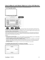
How to Mount and Attach Options to the LCD Monitor
You can attach mounting accessories to the LCD monitor in one of the following two ways:
1. In the upright position
2. Lay the screen face down
Protective Sheet
Table
Handles
Tabletop Stand
Lay the protective sheet on a table, which was wrapped around the monitor when it was packaged, beneath the screen
surface so as not to scratch the screen face.
This device cannot be used or installed without the Tabletop Stand or other mounting accessory. Failure to follow correct
mounting procedures could result in damage to the equipment or injury to the user or installer. Product warranty does not
cover damage caused by improper installation.
Failure to follow these recommendations could result in voiding your warranty.
Use M6 mounting screws (having a length 10 mm longer than the thickness of the mounting bracket) and tighten them
securely. (Recommended torque: 470 - 635N•cm). ViewSonic recommends using mounting interface that comply with
TÜV-GS and/or UL1678 standard in North America.
Caution:
For preventing the monitor from falling.
y Install the monitor with metal brackets for wall or ceiling installation (commercially available) on your own responsibility.
For detailed procedures of installation, refer to the instructions of the metal brackets.
y To lessen the probability of injury and damage resulting from fall of the monitor in case of earthquake or other disaster,
be sure to consult the bracket manufacturer for installation location.
y To lessen the risk of falling of the monitor, thread commercially available rope (having a load capacity at least 1960N
(200kgf)) through the handles at the right and left of the monitor and secure the rope to the wall mount brackets or
ceiling mount brackets.
y Do not sleep where the monitor may topple over or fall in case of an earthquake or other disaster.
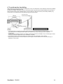
3. Ventilation Requirements for enclosure mounting
To allow heat to disperse, leave space between surrounding objects as shown in the diagram below.
ViewSonic CD4620
13
4. To avoid monitor from falling
Take measures to prevent the monitor from falling over in case of an earthquake or other disaster to lessen the probability
of injury and damage resulting from fall.
As shown in the figure, secure the monitor to a solid wall or pillar using rope (commercially available) strong enough to
bear the weight of the monitor. (CD4620: approx. 34.6 kg) When you use screw hooks (commercially available), ring
screw hooks, not C-shaped screw hooks (with opening), are recommended.
Screw hook, etc.
Commercially available
Screw Holes
Rope, etc.
Commercially available
Clamper
Screw
* Clamper and Screw is not supply.
Caution:
y The effectiveness of preventing from falling substantially depends on the strength of brackets and base to which
prevention device from falling is attached. When you cannot ensure sufficient strength, provide adequate
reinforcement.
y Though the recommended prevention from falling is intended to lessen the probability of injury and damage, it doesn’t
assure its effectiveness against any kind of earthquake or disaster.
y Do not sleep where the monitor may topple over or fall in case of an earthquake or other disaster.
y Before moving the monitor, remove the rope that is securing the monitor. Failure to do so may result in injury or
breakdown of the monitor.
ViewSonic CD4620
14
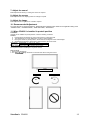
Connections
Before making connections:
7
7
First turn off the power of all the attached equipment and make connections.
Refer to the user manual included with each separate piece of equipment.
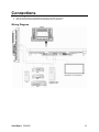
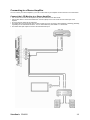
Wiring Diagram
DVD
LCD monitor (second monitor)
HD
Equipment with
Digital interface
PC
VCR
ViewSonic CD4620
15
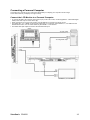
Connecting a Personal Computer
Connecting your computer to your LCD monitor will enable you to display your computer's screen image.
Some video cards may not display an image correctly.
Connect the LCD Monitor to a Personal Computer
y To connect the RGB 3 IN connector (mini D-sub 15 pin) on the LCD monitor, use the supplied PC - Video RGB signal
cable (mini D-sub 15 pin to mini D-sub 15 pin).
y When connecting one or more LCD monitors, use the RGB OUT connector (mini D-sub 15 pin).
y The AUDIO IN 1, 2, 3 or HDMI can be used for audio input. For connection, select AUDIO 1, 2, 3 or HDMI from the
AUDIO INPUT button. You can select HDMI only when RGB 1 or 2 is selected.
y The AUDIO OUT jack outputs sound from the selected Audio input.
To audio output
To analog RGB output
LCD monitor (second monitor)
ViewSonic CD4620
16
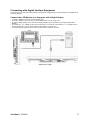
Connecting with Digital Interface Equipment
Connections can be made with equipment that is equipped with a digital interface compliant with the DVI (Digital Visual
Interface) standard.
Connect the LCD Monitor to a Computer with a Digital Output
y The RGB 1, RGB 2 IN connector accepts a HDMI cable.
y The RGB 1, RGB 2 IN connector can connect to HDMI output or DVI-D output of PC.
y To maintain display quality, use a cable with a quality prescribed by DVI standards. (See 29 page “HDMI INPUT
MODE” )
y The AUDIO IN 1, 2, 3 or HDMI can be used for audio input. For connection, select AUDIO 1, 2 , 3 or HDMI from the
AUDIO INPUT button. You can select HDMI only when RGB 1 or 2 is selected.
y The signal input from HDMI connector cannot be output to the RGB OUT connector.
* Cables are not supply.
ViewSonic CD4620
17
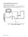
Connecting a DVD Player with component out
Connecting your DVD player to your LCD monitor will enable you to display DVD video.
Refer to your DVD player owner’s manual for more information.
Connect the LCD Monitor to a DVD Player
y To connect the DVD/HD In connector (BNC) on the LCD monitor, use a separately available BNC connector cable. You
will need a BNC-to-RCA adapter to connect a DVD player with an RCA pin jack to the BNC connector cable (not
provided).
y The AUDIO IN 2 and 3 (both RCA) can be used for audio input. For connection, select [AUDIO 1], [AUDIO 2], [AUDIO 3]
or [HDMI] from the AUDIO INPUT button. You can select HDMI only when RGB 1 or 2 is selected.
ViewSonic CD4620
18
Connecting to a Stereo Amplifier
You can connect your stereo amplifier to your LCD monitor. Refer to your amplifier owner's manual for more information.
Connect the LCD Monitor to a Stereo Amplifier
y Turn on the LCD monitor and the amplifier only after all connections have been made.
y Use an RCA cable to connect the AUDIO OUT connector (RCA) on the LCD monitor and the audio input on the
amplifier.
y Do not reverse the audio left and right jacks.
y The AUDIO IN 2 and 3 (both RCA) can be used for audio input. For connection, select [AUIDO1], [AUDIO2], [AUDIO3]
or [HDMI] from the AUDIO INPUT button. You can select HDMI only when RGB 1 or 2 is selected.
y The AUDIO OUT jack outputs sound from the selected Audio input.
ViewSonic CD4620
19
Basic Operation
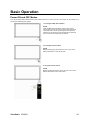
Power ON and OFF Modes
The LCD monitor power indicator will turn green while powered on or red in off mode. The monitor can be powered on or
off using the following three options:
1. Pressing the Main Power Switch.
NOTE:
When the Main Power Switch is used to power off the
LCD monitor, the remote control and the power button will
not activate the on mode and both green and red power
indicator turn off. Be sure to turn the Main Power Switch to
the on mode before using these two options.
2. Pressing the power button.
NOTE:
Before pressing the power button, be sure to turn on the
Main Power button on the LCD monitor.
3. Using the remote control.
NOTE:
Before operating the remote control, be sure to turn on the
Main Power Switch on the LCD monitor.
ViewSonic CD4620
20
Power Indicator
Power ON
Power OFF
Power Standby when
“SCHEDULE” is enable
Power Standby
Diagnosis
(Detecting failure)
Status
Green
Red
Red On
Green Blinking
Red, Green
Red Blinking
* See troubleshooting
Using Power Management
The LCD monitor follows the VESA approved DPM Power Management function.
The power management function is an energy saving function that automatically reduces the power consumption of the
display when the keyboard or the mouse has not been used for a fixed period.
The power management feature on your new display has been set to the “ON” mode. This allows your display to enter a
Power Saving Mode when no signal is applied. This could potentially increase the life and decrease the power
consumption of the display.
Selecting a video source To view a video source:
Use the input button to set [VIDEO].
Use the COLOR SYSTEM menu to set [AUTO], [NTSC], [PAL], [SECAM], [PAL60], [4.43NTSC], according to your video
format.
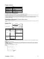
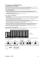
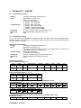
Picture Size
RGB 1, 2, 3
FULL
NORMAL
DVD/HD, VIDEO
FULL
NORMAL
CUSTOM
REAL
REAL
Signal Type
NORMAL SIZE
4:3
DYNAMIC
CUSTOM
Recommended Size
NORMAL
DYNAMIC
FULL
Squeeze
NORMAL: Display by the inputted signal aspect ratio by PC signal, or display in 4:3 aspect ratio at DVD/HD or VIDEO
signal.
FULL: Display in entire screen.
DYNAMIC: Expand 4:3 pictures to the entire screen with non-linearity. (Some round image will be cut by expansion.)
CUSTOM (ZOOM): Image can be expanded beyond the active display area. The image which is outside of active diaplay area is not displayed.
REAL: Image will be displayed 1 by 1 pixel.
ZOOM
ZOOM
ViewSonic CD4620
21
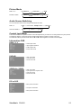
Picture Mode
RGB 1, 2, 3
HIGHBRIGTH
STANDARD
sRGB
DVD/HD, VIDEO
HIGHBRIGTH
STANDARD
CINEMA
Audio Source Switching
You can switch the audio source using the AUDIO INPUT button.
RGB 1, 2
HDMI
AUDIO1
Other than RGB 1, 2
AUDIO1
AUDIO2
AUDIO2
AUDIO3
AUDIO3
Control Lock Mode
This function disables the operation buttons so that the adjustments you make are not changed when they are pressed.
To disable the buttons, press and hold down the S and T buttons together for at least 3 seconds.
To enable the buttons, press and hold down the S and T buttons together for at least 3 seconds again.
Information OSD
RGB1, 2, 3
←Video Input mode
←Input signal Information
←Audio input mode
←Picture Size mode
DVD/HD
←Video Input mode
←Audio input mode
←Picture Size mode
VIDEO<S>, VIDEO
←Video Input mode
←Input Signal Colour System mode
←Audio input mode
←Picture Size mode
PIP or POP
←Main picture Information
←Sub picture Information
←Main picture Information
ViewSonic CD4620
22
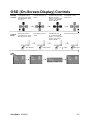
OSD (On-Screen-Display) Controls
Remote
Control
Press MENU button to
open Main menu. Press
S or T button to select
sub-menu.
Press ENTER button to
decide.
Press S or T, and W or
X button to select
function, or control which
you like. Press ENTER
button to decide.
Press MENU or EXIT
button to exit.
Control
Panel
Press EXIT button to
open Main menu. Press
S or T button to select.
Press INPUT button to
decide
Press S or T, and ﹢
or – button to select
function, or control which
you like. Press INPUT
button to decide
Press EXIT button to exit.
S or T button
INPUT button
– or ﹢ button
EXIT button
OSD
Screen
ViewSonic CD4620
23
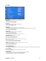
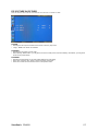
PICTURE
BRIGHTNESS
y Adjusts the overall image and background screen brightness.
y Press + button to increase brightness.
y Press - button to decrease brightness.
CONTRAST
y Adjusts the image brightness in relation to the input signal.
y Press + button to increase contrast.
y Press - button to decrease contrast.
SHARPNESS
y
y
y
y
This function is digitally capable to keep crisp image at any timings.
It is adjustable to get a distinct image or a soft one as you prefer and set independently for each picture mode.
Press + button to increase sharpness.
Press - button to decrease sharpness.
BLACK LEVEL
y
y
y
y
Adjusts the image brightness in relation to the background.
Press + button to increase black level.
Press - button to decrease black level.
NOTE: sRGB picture mode is standard and cannot be changed.
NOISE REDUCTION * : INPUT VIDEO<S>, VIDEO only
y Adjusts the noise reduction level.
y Press + button to increase reduction level.
y Press - button to decrease reduction level.
TINT * : INPUT RGB1, 2(HDMI INPUT MODE-HD), DVD/HD, VIDEO<S>, VIDEO only
y Adjust the tint of the screen.
y Press + button the flesh tone color becomes greenish.
y Press - button the flesh tone color becomes purplish.
COLOR * : INPUT RGB1, 2(HDMI INPUT MODE-HD), DVD/HD, VIDEO<S>, VIDEO only
y Adjust the color of the screen.
y Press + button to increase color depth.
y Press - button to decrease color depth.
COLOR TEMPERATURE
y Use to adjust the color temperature.
y The image becomes reddish as the color temperature decreases, and it becomes bluish as the color temperature increases.
COLOR CONTROL
y The color levels of red, green, and blue are adjusted by the color bars.
y R: Red, G: Green, B: Blue
PICTURE RESET
y Selecting Picture reset allows you to reset all OSD settings about PICTURE setting.
y Select “Yes” and press “SET” button to restore to factory preset data.
y Press “EXIT” button to cancel and then return to the previous menu.
ViewSonic CD4620
24
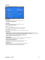
SCREEN
H POSITION
y Controls Horizontal Image position within the display area of the LCD.
y Press + button to move screen to right.
y Press - button to move screen to left.
V POSITION
y Controls Vertical Image position within the display area of the LCD.
y Press + button to move screen to UP.
y Press - button to move screen to DOWN.
CLOCK * : INPUT RGB3,4 only
y Press + button to expand the width of the image on the screen the right.
y Press - button to narrow the width of the image on the screen the left.
CLOCK PHASE * : INPUT RGB3,4 only
y Improves focus, clarity and image stability by increasing or decreasing this setting.
ZOOM MODE
y You can select “FULL”, “NORMAL” and “CUSTOM” and “REAL”. (INPUT RGB1/2/3/4 only) You can also select “FULL”,
“NORMAL” “DYNAMIC” and “CUSTOM” and “REAL”. (INPUT DVD/HD, VIDEO<S>, VIDEO only)
y Selecting “DYNAMIC” will make the screen display panoramic with the expansion of the middle and outside of the screen
changed. (The upper and the bottom of the image will be cut by expansion.)
y Dynamic image is the same as FULL size image when HDTV signal is input.
y Selecting “REAL” image will be displayed 1 by 1 pixel.
CUSTOM ZOOM
y
y
y
y
y
y
“CUSTOM ZOOM” will be selected when you select “CUSTOM” on the screen “ZOOM” mode.
ZOOM: expands the horizontal and the vertical size simultaneously.
HZOOM: expands the horizontal size only.
VZOOM: expands the vertical size only.
H POSITION: moves to the right with + button. moves to the left with – button.
V POSITION: moves up with + button. moves down with – button.
SCREEN RESET
y Selecting Screen reset allows you to reset all OSD settings from PICTURE setting.
y Select “Yes” and press “SET” button to restore the factory preset data.
y Press “EXIT” button to cancel and then return to the previous menu.
ViewSonic CD4620
25
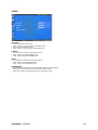
AUDIO
BALANCE
y
y
y
y
Adjust the balance of L/R volume.
Press + button to move the stereo sound image to right.
Sound of the left side will be small.
Press - button to move the stereo sound image to left.
TREBLE
y To accentuate or reduce the high frequency sound.
y Press + button to increase TREBLE sound.
y Press - button to decrease TREBLE sound.
BASS
y To accentuate or reduce the low frequency sound.
y Press + button to increase BASS sound.
y Press - button to decrease BASS sound.
AUDIO RESET
y Selecting Audio reset allows you to reset all OSD settings from AUDIO setting.
y Select “YES” and press “SET” button to restore the factory preset.
y Press “EXIT” button to cancel and then return to the previous menu.
ViewSonic CD4620
26
PIP (PICTURE IN PICTURE)
Note: The “PIP” and “POP” modes do not function when the screen size is “CUSTOM” or “REAL”.
PIP SIZE
y Selecting the size of picture inserted at the “Picture-in-Picture” (PIP) mode.
y “Large”, “Middle” and “Small” are available.
PIP AUDIO
y Selecting the sound source in PIP mode.
y When selecting “MAIN AUDIO”, you will get the sound for the main picture and when selecting “PIP AUDIO”, you will get the
sound for the picture instead.
PIP RESET
y Selecting PIP Reset allows you to reset all OSD settings from PIP setting.
y Select “Yes” and press “SET” button to restore the factory preset data.
y Press “EXIT” button to cancel and then return to the previous menu.
ViewSonic CD4620
27
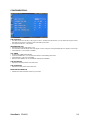
CONFIGURATION 1
AUTO SETUP * : INPUT RGB3,4 only
y Press "SET" button to automatically adjust screen size, horizontal position, vertical position, clock, clock phase, white level and
black level.
y Press "EXIT" button to cancel execution AUTO SETUP and then will return to the previous menu.
AUTO ADJUST * : INPUT RGB3,4 only
y Selecting the auto adjust ON/OFF.
y Selecting ON when changing the timing, the horizontal position, vertical position and clock-phase will adjust automatically.
POWER SAVE
y Selecting RGB "ON", the monitor will go to power management mode when RGB1,2,3,4 sync is lost.
y Selecting VIDEO "ON", the monitor will go to power management mode after about 10 minutes delay from when DVD/HD and
VIDEO input signal is lost.
LANGUAGE
y OSD control menus are available in eight languages. (English, German, Spanish, French, Chinese and Russian)
SCREEN SAVER *Select "SCREEN SAVER" functions to reduce the risk of the "image persistence".
y BRIGHTNESS: The brightness is decreased when selected "ON".
y MOTION: Image is slightly expanded and moves 4 directions (UP, DOWN, RIGHT, LEFT) periodically (Need setting the time
for movement).
y Movement area is approximately +/- 10mm from original position;
y Please locate the important information such as text within 90% area of screen image.
y See note (1) for this functions.
y PIP and STILL will be disabled when "MOTION" is active.
COLOR SYSTEM * : INPUT VIDEO<S>, VIDEO only
y
y
y
y
y
y
y
Selecting the Color System depends on your input video format.
AUTO: NTSC, PAL, SECAM, PAL60 or 4.43 NTSC is automatically selected.
NTSC: Specific selection of NTSC.
PAL: Specific selection of PAL.
SECAM: Specific selection of SECAM.
PAL-60: Specific selection of PAL60.
4.43NTSC: Specific selection of 4.43 NTSC.
CONFIGURATION RESET
y Selecting the CONFIGURATION RESET allows you to reset all configuration settings.
y Select "Yes" and press "SET" button to restore the factory preset data.
y Press "EXIT" button to cancel and return the previous menu.
FACTORY RESET
y Selecting "YES" allows you to reset PICTURE, SCREEN, AUDIO, CONFIGURATION1,2 and ADVANCED OPTION will be
back to factory settings (except LANGUAGE, DATE & TIME and SCHEDULE).
y Select "YES" and press "SET" button to restore the factory preset data. Press "EXIT" button to cancel and return the previous
menu.
ViewSonic CD4620
28
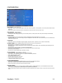
CONFIGURATION 2
OSD TURN OFF
y The OSD control menu will stay on as long as it is use. In the OSD Turn Off submenu, you can select how long the monitor
waits after the last touch of a button to shut off the OSD control menu.
y The preset choices are 5 -120 seconds.
INFORMATION OSD
y Selects the information OSD display or not.
y The information OSD will display when input signal or source change or warning message like as no-signal or out-of range.
y A time between 1 to 10 seconds is available.
OFF TIMER
y
y
y
y
To select OFF TIMER mode ON/OFF.
In the OFF TIMER menu, you can preset the monitor to automatically power down.
A time between 1 to 24 hours is available.
When the OFF TIMER is set, the SCHEDULE settings will be disabled.
OSD H POSITION
y Adjusts the horizontal position of the OSD menu.
OSD V POSITION
y Adjusts the vertical position of the OSD menu.
MONITOR INFORMATION
y Indicates the model and serial number of your monitor.
ViewSonic CD4620
29
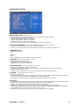
ADVANCED OPTION
INPUT RESOLUTION * : INPUT RGB3,4 only
y
y
y
y
y
y
Selects to decision of input signal about below timings, 1024x768, 1280x768 and 1360x768.
AUTO: Determines the resolution automatically.
1024x768: Determines the resolution as 1024x768
1280x768: Determines the resolution as 1280x768
1360x768: Determines the resolution as 1360x768
The setting you select becomes effective when POWER is turned OFF and ON again.
BLACK LEVEL EXPANSION * : INPUT RGB1,2(HDMI INPUT MODE-HD), VIDEO<S>, VIDEO only
y Selects a level of black expansion from “OFF”, “MIDDLE” and “HIGH.”
y In case of go under the black cut-off level, please adjust the “Black level” in moderation on OSD menu.
GAMMA SELECTION
y
y
y
y
y
y
Selects a display gamma.
2.2
2.4
S gamma
Native
NOTE: sRGB picture mode is standard and cannot be changed.
SCAN MODE * : INPUT DVD/HD, VIDEO<S>, VIDEO only
y Changes the display area of the image.
y OVERSCAN: Set to display area about 95%
y UNDERSCAN: Set to display area about 100%
SCAN CONVERSION * : INPUT DVD/HD, VIDEO<S>, VIDEO only
y
y
y
y
Selects IP (Interlace to Progressive) converter function.
PROGRESSIVE: Enable the IP function, to convert interlace signal to progressive. Normally use this setting.
INTERLACE*: Disable the IP function.
*NOTE: This mode is better suited for motion pictures, but it increases chance of image retention.
FILM MODE * : INPUT DVD/HD, VIDEO<S>, VIDEO only
y Selects Film mode function.
y AUTO: Enable the Film mode function. This mode is better suited for movies, which is converted 24 Frames/sec source to
DVD Video. We recommend to select “PROGRESSIVE” in “SCAN CONVERSION”.
y OFF: Disable the Film mode function. This mode is better suited for Broadcasting or VCR source.
IR CONTROL
y
y
y
y
y
y
y
Selects the operation mode of the wireless remote controller when multiple CD4620 monitors are connected via RS-232C.
The item in this menu will become effective by pressing “SET” button on the selected item.
NORMAL: The monitor will be controlled normally by wireless remote controller.
PRIMARY: The first CD4620 monitor of those multi-connected via RS-232C is designated as PRIMARY.
SECONDARY: CD4620 monitors other than the first one multi-connected via RS-232C are designated as SECONDARY.
LOCK: Disable the monitor control by infrared wireless remote controller.
Keep pressing “DISPLAY” button during 5 sec or more, this setting will return to “NORMAL”.
ViewSonic CD4620
30
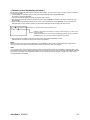
TILING
TILING demonstrates multiple screens. This feature provides a single large screen using up to 25 monitors.
It will be able to divide up to 5 each H and V.
This requires you to feed the PC output into each of the monitors through a distributor.
H MONITORS: Select number of horizontal divide.
V MONITORS: Select number of vertical divide.
POSITION: Select a position to expand the screen.
FRAME COMP: Works in tandem with TILING to compensate for the width of the tile bezels in order to accurately display the
image.
y ENABLE: Select “YES”, the monitor will expand the selected position.
y PIP and STILL will be disabled when “TILING” is activated.
y
y
y
y
y
y
y
POWER ON DELAY
y Adjusts the delay time from “standby” to “power on” mode.
y “POWER ON DELAY” time is selectable from OFF, 2sec, 4sec, 6sec, 8sec, 10sec, 20sec, 30sec, 40sec and 50sec.
DATE AND TIME
y Adjusts the current date and time for internal clock.
y You should set this function when you use “SCHEDULE”.
SCHEDULE
y Programs the monitor's working schedule.
y Schedule the power on and power off with hour and a day of the week. Also sets the input port.
y This OSD can't remove except EXIT. (see “NOTE 2” on page 30 for further information)
MONITOR ID
y ID numbers for remote control are assigned to CD4620 monitors that are multi-connected via RS-232C.
y ID numbers 1 to 26 are selectable.
DDC/CI
y Use to turn ON or OFF the DDC/CI communication function. Select ON for normal use.
SYNC TYPE
y Select “0.3V” for 0.3 Composite Sync.
y Select “TTL” for TTL Sync.
ADVANCED OPTION RESET
y Selecting ADVANCED OPTION reset allows you to reset all OSD settings from ADVANCED OPTION settings, except for
DATE & TIME.
y Select “YES” and press “SET” button to restore the factory preset data.
y Press “EXIT” button to cancel and then return the previous menu.
NOTE 1: IMAGE PERSISTENCE
y Please be aware that LCD Technology may experience a phenomena known as Image Persistence. Image Persistence
occurs when residual or “ghost” image of a previous image remains visible on the screen. Unlike CRT monitors, LCD
monitors’ image persistence is not permanent, but constant images being displayed for a long period of time should be
avoided.
y To alleviate image persistence, turn off the monitor for as long as the previous image was displayed. For example, if an
image was on the monitor for one hour and a residual image remains, the monitor should be turned off for one hour to
erase the image.
y As with all personal display devices, ViewSonic recommends displaying moving images and using a moving screen
saver at regular intervals whenever the screen is idle or turning off the monitor when not in use.
Please set “POWER SAVE”, “SCREEN SAVER”, “DATE &TIME” and “SCHEDULE” functions to further reduce the risk
of Image persistence.
ViewSonic CD4620
31
For long life use of Public Display
< Image Sticking of LCD Panel >
When LCD panel is operated continuously for long hours, a trace of electric charge remains near the electrode inside
LCD, and residual or “ghost” image of previous image may be observed. (Image Persistence)
Image Persistence is not permanent, but when fixed image is displayed for long period, ionic impurities inside LCD are
accumulated along the displayed image, and it is observed permanently. (Image Sticking)
< Recommendations >
For preventing the fast transition to Image Sticking, and for longer life usage of LCD, following are recommended.
1. Fixed image should not be displayed for long period, and changed to another images with short cycle.
2. When no use, please turn off the monitor by remote control, or use Power Management Function of monitor or use
Schedule Function of monitor.
3. Reducing the environmental temperature is effective for long life use.
4. Please use "Screen Saver Mode" of monitor.
NOTE 2: HOW TO SETUP SCHEDULE
y Using the “SCHEDULE” function allows you to set up to seven different scheduled time intervals when the LCD Monitor
will be activated.
y You can select the time the monitor turns on and turns off, the day of week the monitor is activated, and which input
source the monitor will use for each scheduled activation period. A check mark in the box next to the number of the
schedule indicates that the selected schedule is in effect.
y To select which schedule to set, use the up/down arrows to move the number (1 to 7) of the schedule.
y Use the (+) and (-) buttons to move the cursor horizontally within the particular schedule. Use the (S) and (T) buttons
to increase time and select input port. The “SET” button is used to make a selection.
y If you create a schedule but do not want to use a power on time, select “--” in the “ON” time slot.
y If you do not want to use a power off time select “--” in the OFF time slot.
y If there is no input selected (“--” showing in the input spot) the input from the previous schedule will be used.
y The selection of EVERY DAY within a schedule takes priority over other schedules that are set up to operate weekly.
y When schedules are overlapping, scheduled Power ON time has priority over scheduled Power OFF time.
y If there are two schedules programmed for the same time, then the highest numbered schedule has priority.
When the “OFF TIMER” is set, the “SCHEDULE” function is disabled.
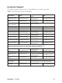
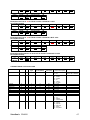
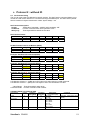
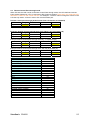
NOTE 3: “PIP”, “POP” and “SIDE BY SIDE”
The following table shows the combination of signal inputs under which the “PIP” and “POP” modes function. These
modes do not function however when the screen size is “CUSTOM” or “REAL”.
MAIN
SUB
RGB1
RGB2
RGB3
RGB4
DVD/HD
RGB1
±
±
±
±
±
VIDEO<S> VIDEO
{
{
RGB2
±
±
±
±
±
{
{
{:Supported
RGB3
±
±
±
±
±
{
{
±: Not supported
DVD/HD
±
±
±
±
±
{
{
VIDEO<S>
{
{
{
{
{
±
±
VIDEO
{
{
{
{
{
±
±
Press the “PIP ON/OFF” buttons on the remote control to change between “PIP”, “POP” and “SIDE BY SIDE” mode as
shown in the diagram below.
PIP
POP
SIDE BY SIDE
ASPECT
SIDE BY SIDE
FULL
OFF
"PIP”, “POP” mode resolution (Reference)
PIP SIZE
POP SIZE
YSMALLZ
YMIDDLEZ
YLARGEZ
: 450 dots X 338 dots
: 675 dots X 450 dots
: 900 dots X 675 dots
: 450 dots X 338 dots
ViewSonic CD4620
32
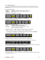
< Remote control numbering function >
By connecting multiple CD4620 monitors using RS-232C cables, you can control any one monitor or all the monitors by
one remote controller.
1. Assign arbitrary ID number to each of multi-connected CD4620 monitors using MONITOR ID.
ID numbers 1 to 26 are selectable.
It is recommended to assign sequential ID numbers from 1 and up.
2. The remote control mode of the first CD4620 monitor is set to PRIMARY and those of the other monitors are set to
SECONDARY.
3. When you direct the remote controller at the remote control signal sensor of the PRIMARY monitor and press the
DISPLAY button on the remote controller, the ID selection OSD appears at the upper left of the screen.
ID number of the currently viewed monitor
Select the ID number of the monitor you want to control using the +/- button on the
remote controller.
The ID of the monitor you want to control is displayed at the upper left of its screen.
By selecting ALL, you can control all the multi-connected monitors.
4. Direct the remote controller at the remote control signal sensor of the PRIMARY monitor.
OSD appears on the monitor having the ID number you selected.
NOTE:
When the ID selection OSD is being displayed on the PRIMARY monitor, press the DISPLAY button on the remote
controller again to cancel the ID selection OSD and then control the monitor you selected.
HINT:
If you set the remote control mode wrongly and remote control operation becomes unavailable, press any button on the
control panel of the monitor to display the OSD screen and change the remote control mode using ADVANCED OPTION.
By pressing and holding down the DISPLAY button on the remote control for 5 seconds or longer, the remote control
mode is initialized to NORMAL.
ViewSonic CD4620
33
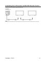
Controlling the LCD monitor via RS-232C Remote Control
This LCD monitor can be controlled by connecting a personal computer with a RS-232C terminal.
Functions that can be controlled by a personal computer are:
Connection
LCD Monitor + PC
NOTE:
We have two kinds of RS-232 protocol including serious connection and no serious connection that can use by user.
ViewSonic CD4620
34
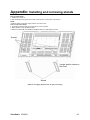
Appendix: Installing and removing stands
How to install stands
1. Please turn monitor off.
2. After inserting stand in guide block, fasten Thumbscrews on both sides of the monitor.
NOTE:
Install the stands so that their longer portions come to the front.
How to remove the stands
1. Spread the protective sheet on the fl at surface, such as a desk.
2. Place monitor on the protective sheet.
3. Remove screws with a screwdriver and place them in a safe place for reuse.
Screws
Longer portion comes to
the front.
Stands
* Stand is not supply. (Stand sold as an option accessory)
ViewSonic CD4620
35
Features
Reduced Footprint:
Provides the ideal solution for environments requiring superior image quality but with size and weight limitations.
The monitor’s small footprint and low weight allow it to be moved or transported easily from one location to another.
Color Control Systems:
Allows you to adjust the colors on your screen and customize the color accuracy of your monitor to a variety of standards.
sRGB Color Control:
A new optimized color management standard which allows for color matching on computer displays and other peripherals. The
sRGB standard, which is based on a calibrated color space, allows for optimal color representation and backward compatibility
with other common color standards.
OSD (On-Screen-Display) Controls:
Allow you to quickly and easily adjust all elements of your screen image via simple to use on-screen menus.
Plug and Play:
The Microsoft® solution with the Windows® 95/98/Me/2000/XP operating system facilitates setup and installation by allowing the
monitor to send its capabilities (such as screen size and resolutions supported) directly to your computer, automatically
optimizing display performance.
Intelligent Power Manager System:
Provides innovative power-saving methods that allow the monitor to shift to a lower power consumption level when on but not in
use, saving two-thirds of your monitor energy costs, reducing emissions and lowering the air conditioning costs of the workplace.
Multiple Frequency Technology:
Automatically adjusts monitor to the display card’s scanning frequency, thus displaying the resolution required.
FullScan Capability:
Allows you to use the entire screen area in most resolutions, significantly expanding image size.
Wall Mounting Interface:
Allows for the monitor to be mounted on a wall or an arm using any third party compliant device. VIEWSONIC recommends using
mounting interface that comply with TÜV-GS and/or UL1678 standard in North America.
TILING, Frame compensation:
Demonstrates multiple screens with an accurate image and compensates for the bezel width.
ZOOM:
Expands the image individually for horizontal and vertical direction.
Self-diagnosis:
When an internal error should occur, a failure state will be indicated.
ViewSonic CD4620
36
Troubleshooting
No picture
• The signal cable should be completely connected to the display card/computer.
• The display card should be completely seated in its slot.
• Front Power Switch and computer power switch should be in the ON position.
• Check to make sure that a supported mode has been selected on the display card or system being used.
(Please consult display card or system manual to change graphics mode.)
• Check the monitor and your display card with respect to compatibility and recommended settings.
• Check the signal cable connector for bent or pushed-in pins.
• If nothing is displayed on the screen when HDCP device is connected, reset the power of the device.
Power Button does not respond
• Unplug the power cord of the monitor from the AC outlet to turn off and reset the monitor.
Image persistence
• Please be aware that LCD Technology may experience a phenomenon known as Image Persistence. Image
Persistence occurs when a residual or “ghost” image of a previous image remains visible on the screen. Unlike CRT
monitors, LCD monitors’ image persistence is not permanent, but constant images being displayed for a long period of
time should be avoided. To alleviate image persistence, turn off the monitor for as long as the previous image was
displayed. For example, if an image was on the monitor for one hour and a residual image remains, the monitor should be
turned off for one hour to erase the image.
NOTE:
As with all personal display devices, VIEWSONIC recommends displaying moving images and using a moving screen
saver at regular intervals whenever the screen is idle or turning off the monitor when not in use.
Image is unstable, unfocused or swimming is apparent
• Signal cable should be completely attached to the computer.
• Use the OSD Image Adjust controls to focus and adjust display by increasing or decreasing the fine adjustment.
When the display mode is changed, the OSD Image Adjust settings may need to be re-adjusted.
• Check the monitor and your display card with respect to compatibility and recommended signal timings.
• If your text is garbled, change the video mode to non-interlace and use 60 Hz refresh rate.
Image of component signal is greenish
• Check to see if the DVD/HD input connector is selected.
LED on monitor is not lit (no green or red color can be seen)
• Power Switch should be in the ON position and power cord should be connected.
• Make certain the computer is not in a power-saving mode (touch the keyboard or mouse).
RED LED on monitor is blinking
• A certain failure might have occurred, please contact your nearest authorized VIEWSONIC service facility.
Display image is not sized properly
• Use the OSD Image Adjust controls to increase or decrease the coarse adjustment.
• Check to make sure that a supported mode has been selected on the display card or system being used.
(Please consult display card or system manual to change graphics mode.)
Selected resolution is not displayed properly
• Use OSD Display Mode to enter Information menu and confirm that the appropriate resolution has been selected.
If not, select corresponding option.
No Sound
• Check to see if speaker cable is properly connected.
• Check to see if mute is activated.
• Check to see if volume is set at minimum.
Remote Control is not available
• Check the Remote Control’s batteries status.
• Check if batteries are inserted correctly.
• Check if the Remote Control is pointing at the monitor’s remote sensor.
“SCHEDULE”/“OFF TIMER” function is not working properly
• The “SCHEDULE” function will be disabled when the “OFF TIMER” is set.
• If the “OFF TIMER” function is enable and the power to the LCD monitor is turned off if the power supply is interrupted
unexpectedly, then the “OFF TIMER” will be reset.
Stripe Noise
Either light vertical or horizontal stripes may appear, depending on the specific display pattern. This is no product fault or
degradation.
“NO SIGNAL” is displayed on the screen
Image may not be displayed right after HDCP device is connected.
ViewSonic CD4620
37
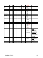
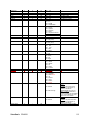
Specifications
Product specifications
LCD Module
Frequency
Diagonal:
Pixel Pitch:
Resolution:
Color:
Brightness:
Contrast Ratio:
Response time:
View Angle:
Design View Distance:
Horizontal:
Vertical:
Pixel Clock
Viewable Size
Input Signal
PC-Input:
Video:
Sync:
Input-terminal:
VIDEO Input:
AUDIO Input:
RS-232C:
Output Signal
PC-Output:
In:
Video:
Sync:
Output-terminal:
VIDEO Output:
AUDIO Output:
Speaker Output:
RS-232C:
Out:
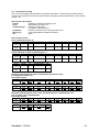
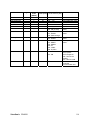
Resolutions Supported
Power Supply
Power Consumption
Operational
Environment
Storage Environment
Dimension
Weight
Power Save:
Temperature:
Humidity:
Temperature:
Humidity:
Net without stand:
Net with stand:
Gross:
Net without stand:
Net with stand:
Gross:
Wall mounting interface
Complied Regulatory and Guidelines
Power Management
Plug & Play
Accessories
Analog Input
46" / 116.8 cm
0.53025 mm
1920 x 1080 dots
Over 16 million colors (depending on video card used)
450 cd/m2 (typ.)
1500:1 (typ.)
6 ms (typ. G to G)
Up and Down 176°, Left and Right 176° (typ.) @CR>10
1100 mm / 43.34 inches
15.625 / 15.734, 31.5 - 91.1 kHz
50.0 / 58.0 - 85.0 Hz
13.5 -165.0 MHz
1018.08 x 572.67 mm / 40.1 x 22.5 inches
Digital Input
25.0 -165.0 MHz
Analog RGB Video: 0.7 Vp-p
TMDS
Input impedance 75 ohm
Separate HV sync: TTL level (Pos./Neg.), Sync-on-green, Composite Sync
(0.3Vp-p) Input Impedance 2.2K ohm
HDMI
Composite: 1.0 Vp-p
Input impedance 75ohm BNC and RCA-PINJACK-INPUT Y/C Y: 1 Vp-p C:
0.286 Vp-p Input
Impedance 75 ohm S-TERMINAL-INPUT Component: 1.0 / 0.7 Vp-p
Input Impedance 75 ohm BNC-INPUT
RCA PIN-JACK L/R INPUT x 2, STEREO Mini Jack INPUT x 1
9 Pin Mini D-sub
Analog RGB Video: 0.7 Vp-p with 75 ohm terminated
Separate HV sync: TTL level (Pos./Neg.)
15 Pin Mini D-sub
BNC-OUTPUT x 1, Composite 1.0 Vp-p with 75 ohm terminated
RCA PIN-JACK L/R OUTPUT x 1, 0.15 Vrms with 47k ohm terminated
External Speaker Jack 7 W + 7 W (8 ohm)
9 Pin Mini D-sub
640 x 480 at 60 Hz to 85 Hz
800 x 600 at 50 Hz, 60Hz to 85 Hz
1024 x 768 at 50 Hz, 60Hz to 85 Hz
1280 x 768 at 50 Hz, 60Hz to 85 Hz
1360 x 768 at 50 Hz, 60Hz to 85 Hz
1280 x 1024 at 60Hz to 85 Hz
1600 x 1200 at 60 Hz
1920 x 1080 at 60Hz*
* Recommended Resolution
NTSC,PAL,SECAM,4.43NTSC,PAL60 Component:480i,480p,720p,1080i,1080p
3.2 - 1.38 A @100 - 240 V AC, 50 / 60 Hz
Max 285 W
Less than 5 W (Power button OFF/Main power switch ON)
Landscape: 5 - 40 °C / 41-104 °F, Portrait : 5 - 35 °C / 41 - 95 °F
20 - 80 % (Without condensation)
-20 - 60 °C / -4 - 140 °F
10 - 90% (Without condensation)/90%-3.5%x(Temp-40°C) regarding over 40°C
1122 mm (W) x 663 mm (H) x 136.3 mm (D) / 44.17" (W) x 26.1" (H) x 5.37" (D)
1122 mm (W) x 703.1 mm (H) x 404.7 mm (D) / 44.17" (W) x 27.68" (H) x 15.93" (D)
1285 mm (W) x 885 mm (H) x 275 mm (D) / 50.59" (W) x 37.84" (H) x 10.83" (D)
72.6 lbs / 33.0 kg (Approximately)
76.1 lbs / 34.6 kg (Approximately)
94.6 lbs / 43.0 kg
12 Holes (100 mm pitches) Optional Multi-purpose Fix Mount
C-UL/TUV-GS/FCC-B/DOC-B/C-Tick/CE/BSMI/GOST/PSB
VESA DPM
VESA DDC2B, DDC/CI
User's Manual, Power Cord, Video Signal Cable, Remote Controller,
AAA Battery x 2,
Note: Technical specifications are subject to change without notice.
ViewSonic CD4620
38
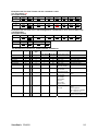
Customer Support
For technical support or product service, see the table below or contact your reseller.
NOTE: You will need the product serial number.
Country/Region
Website
T = Telephone
F = FAX
Email
Australia/New Zealand
www.viewsonic.com.au
AUS= 1800 880 818
NZ= 0800 008 822
[email protected]
Canada
www.viewsonic.com
T= 1-866-463-4775
F= 1-909-468-5814
[email protected]
Europe/Middle East/
Baltic countries/North
Africa
www.viewsoniceurope.com Contact your reseller
Hong Kong
www.hk.viewsonic.com
T= 852 3102 2900
[email protected]
India
www.in.viewsonic.com
T= 1800 11 9999
[email protected]
Korea
www.kr.viewsonic.com
T= 080 333 2131
[email protected]
Latin America (Argentina) www.viewsonic.com/la/
T= 0800-666-0098
F= 1-909-444-5655
[email protected]
Latin America (Brazil)
www.viewsonic.com/la/
T= 0800-891-1829
F= 1-909-444-5655
[email protected]
Latin America (Chile)
www.viewsonic.com/la/
T= 800-440303
F= 1-909-444-5655
[email protected]
Latin America (Columbia) www.viewsonic.com/la/
T= 01800-9-156588
F= 1-909-444-5655
[email protected]
Latin America (Mexico)
T= 001-866-823-2004
F= 1-909-444-5655
[email protected]
www.viewsonic.com/la/
Renta y Datos, 29 SUR 721, COL. LA PAZ, 72160 PUEBLA, PUE. Tel: 01.222.891.55.77 CON 10 LINEAS
Electroser, Av Reforma No. 403Gx39 y 41, 97000 Mérida, Yucatán. Tel: 01.999.925.19.16
Other places please refer to http://www.viewsonic.com/la/soporte/index.htm#Mexico
Latin America (Peru)
www.viewsonic.com/la/
T= 0800-53311
F= 1-909-444-5655
[email protected]
Macau
www.hk.viewsonic.com
T= 853 700 303
[email protected]
Puerto Rico & Virgin
Islands
www.viewsonic.com
T= 1-800-688-6688 (English)
[email protected]
T= 1-866-379-1304 (Spanish)
[email protected]
F= 1-909-468-1202
Singapore/Malaysia/
Thailand
www.ap.viewsonic.com
T= 65 6461 6044
South Africa
www.viewsoniceurope.com www.viewsoniceurope.com/uk/Support/Calldesk.htm
United Kingdom
www.viewsoniceurope.com
www.viewsoniceurope.com/uk/Support/Calldesk.htm
/uk/
United States
www.viewsonic.com
ViewSonic CD4620
T= 1-800-688-6688
F= 1-909-468-1202
[email protected]
[email protected]
39
Limited Warranty
VIEWSONIC® LCD DISPLAY
What the warranty covers:
ViewSonic warrants its products to be free from defects in material and workmanship, under
normal use, during the warranty period. If a product proves to be defective in material or
workmanship during the warranty period, ViewSonic will, at its sole option, repair or replace
the product with a like product. Replacement product or parts may include remanufactured or
refurbished parts or components.
How long the warranty is effective:
ViewSonic LCD displays are warranted for 1 years for all parts including the light source and 1
years for all labor from the date of the first consumer purchase.
Who the warranty protects:
This warranty is valid only for the first consumer purchaser.
What the warranty does not cover:
1. Any product on which the serial number has been defaced, modified or removed.
2. Damage, deterioration or malfunction resulting from:
a. Accident, misuse, neglect, fire, water, lightning, or other acts of nature, unauthorized
product modification, or failure to follow instructions supplied with the product.
b. Any damage of the product due to shipment.
c. Removal or installation of the product.
d. Causes external to the product, such as electrical power fluctuations or failure.
e. Use of supplies or parts not meeting ViewSonic’s specifications.
f. Normal wear and tear.
g. Any other cause which does not relate to a product defect.
3. Any product exhibiting a condition commonly known as "image burn-in" which results
when a static image is displayed on the product for an extended period of time.
4. Removal, installation, one way transportation, insurance, and set-up service charges.
How to get service:
1. For information about receiving service under warranty, contact ViewSonic Customer Support (Please refer to Customer Support page). You will need to provide your product's serial
number.
2. To obtain warranty service, you will be required to provide (a) the original dated sales slip,
(b) your name, (c) your address, (d) a description of the problem, and (e) the serial number
of the product.
3. Take or ship the product freight prepaid in the original container to an authorized
ViewSonic service center or ViewSonic.
4. For additional information or the name of the nearest ViewSonic service center, contact
ViewSonic.
Limitation of implied warranties:
There are no warranties, express or implied, which extend beyond the description contained
herein including the implied warranty of merchantability and fitness for a particular purpose.
4.3: ViewSonic LCD Warranty
ViewSonic CD4620
Page 1 of 2
LCD_LW02 Rev. 1e 06-11-07
40
Exclusion of damages:
ViewSonic's liability is limited to the cost of repair or replacement of the product. ViewSonic
shall not be liable for:
1. Damage to other property caused by any defects in the product, damages based upon inconvenience, loss of use of the product, loss of time, loss of profits, loss of business opportunity, loss of goodwill, interference with business relationships, or other commercial loss,
even if advised of the possibility of such damages.
2. Any other damages, whether incidental, consequential or otherwise.
3. Any claim against the customer by any other party.
4. Repair or attempted repair by anyone not authorized by ViewSonic.
Effect of state law:
This warranty gives you specific legal rights, and you may also have other rights which vary
from state to state. Some states do not allow limitations on implied warranties and/or do not
allow the exclusion of incidental or consequential damages, so the above limitations and
exclusions may not apply to you.
Sales outside the U.S.A. and Canada:
For warranty information and service on ViewSonic products sold outside of the U.S.A. and
Canada, contact ViewSonic or your local ViewSonic dealer.
The warranty period for this product in mainland China (Hong Kong, Macao and Taiwan
Excluded) is subject to the terms and conditions of the Maintenance Guarantee Card.
For users in Europe and Russia, full details of warranty provided can be found in
www.viewsoniceurope.com under Support/Warranty Information.
4.3: ViewSonic LCD Warranty
ViewSonic CD4620
Page 2 of 2
LCD_LW02 Rev. 1e 06-11-07
41
Mexico Limited Warranty
VIEWSONIC® DISPLAY PRODUCTS
What the warranty covers:
ViewSonic warrants its products to be free from defects in material and workmanship, under normal use, during
the warranty period. If a product proves to be defective in material or workmanship during the warranty period,
ViewSonic will, at its sole option, repair or replace the product with a like product. Replacement product or parts
may include remanufactured or refurbished parts or components & accessories.
How long the warranty is effective:
ViewSonic LCD displays are warranted for 1 years for all parts including the light source and 1 years for all labor
from the date of the first consumer purchase.
Who the warranty protects:
This warranty is valid only for the first consumer purchaser.
What the warranty does not cover:
1. Any product on which the serial number has been defaced, modified or removed.
2. Damage, deterioration or malfunction resulting from:
a. Accident, misuse, neglect, fire, water, lightning, or other acts of nature, unauthorized product
modification, unauthorized attempted repair, or failure to follow instructions supplied with the product.
b. Any damage of the product due to shipment.
c. Causes external to the product, such as electrical power fluctuations or failure.
d. Use of supplies or parts not meeting ViewSonic's specifications.
e. Normal wear and tear.
f. Any other cause which does not relate to a product defect.
7. Any product exhibiting a condition commonly known as "image burn-in" which results when a static image is
displayed on the product for an extended period of time.
8. Removal, installation, insurance, and set-up service charges.
How to get service:
For information about receiving service under warranty, contact ViewSonic Customer Support (Please refer to the
attached Customer Support page). You will need to provide your product's serial number, so please record the
product information in the space provided below on your purchase for your future use. Please retain your receipt
of proof of purchase to support your warranty claim.
For Your Records
Product Name: ________________________________
Model Number: _____________________________
Document Number: ____________________________
Serial Number: _____________________________
Purchase Date: ________________________________
Extended Warranty Purchase? ____________ (Y/N)
If so, what date does warranty expire? ___________
1. To obtain warranty service, you will be required to provide (a) the original dated sales slip, (b) your name, (c)
your address, (d) a description of the problem, and (e) the serial number of the product.
2. Take or ship the product in the original container packaging to an authorized ViewSonic service center.
3. Round trip transportation costs for in-warranty products will be paid by ViewSonic.
Limitation of implied warranties:
There are no warranties, express or implied, which extend beyond the description contained herein including the
implied warranty of merchantability and fitness for a particular purpose.
Exclusion of damages:
ViewSonic's liability is limited to the cost of repair or replacement of the product. ViewSonic shall not be liable
for:
1. Damage to other property caused by any defects in the product, damages based upon inconvenience, loss of
use of the product, loss of time, loss of profits, loss of business opportunity, loss of goodwill, interference with
business relationships, or other commercial loss, even if advised of the possibility of such damages.
2. Any other damages, whether incidental, consequential or otherwise.
3. Any claim against the customer by any other party.
4. Repair or attempted repair by anyone not authorized by ViewSonic.
4.3: ViewSonic Mexico Limited Warranty
ViewSonic CD4620
Page 1 of 2
LCD_LW03 Rev. 1a 06-11-07
42
Contact Information for Sales & Authorized Service (Centro Autorizado de Servicio) within Mexico:
Name, address, of manufacturer and importers:
México, Av. de la Palma #8 Piso 2 Despacho 203, Corporativo Interpalmas,
Col. San Fernando Huixquilucan, Estado de México
Tel: (55) 3605-1099
http://www.viewsonic.com/la/soporte/index.htm
NÚMERO GRATIS DE ASISTENCIA TÉCNICA PARA TODO MÉXICO: 001.866.823.2004
Hermosillo:
Villahermosa:
Distribuciones y Servicios Computacionales SA de CV. Compumantenimietnos Garantizados, S.A. de C.V.
Calle Juarez 284 local 2
AV. GREGORIO MENDEZ #1504
Col. Bugambilias C.P: 83140
COL, FLORIDA C.P. 86040
Tel: 01-66-22-14-9005
Tel: 01 (993) 3 52 00 47 / 3522074 / 3 52 20 09
E-Mail: [email protected]
E-Mail: [email protected]
Puebla, Pue. (Matriz):
Veracruz, Ver.:
RENTA Y DATOS, S.A. DE C.V. Domicilio:
CONEXION Y DESARROLLO, S.A DE C.V. Av.
29 SUR 721 COL. LA PAZ
Americas # 419
72160 PUEBLA, PUE.
ENTRE PINZÓN Y ALVARADO
Tel: 01(52).222.891.55.77 CON 10 LINEAS
Fracc. Reforma C.P. 91919
E-Mail: [email protected]
Tel: 01-22-91-00-31-67
E-Mail: [email protected]
Chihuahua
Cuernavaca
Soluciones Globales en Computación
Compusupport de Cuernavaca SA de CV
C. Magisterio # 3321 Col. Magisterial
Francisco Leyva # 178 Col. Miguel Hidalgo
Chihuahua, Chih.
C.P. 62040, Cuernavaca Morelos
Tel: 4136954
Tel: 01 777 3180579 / 01 777 3124014
E-Mail: [email protected]
E-Mail: [email protected]
Distrito Federal:
Guadalajara, Jal.:
QPLUS, S.A. de C.V.
SERVICRECE, S.A. de C.V.
Av. Coyoacán 931
Av. Niños Héroes # 2281
Col. Del Valle 03100, México, D.F.
Col. Arcos Sur, Sector Juárez
Tel: 01(52)55-50-00-27-35
44170, Guadalajara, Jalisco
E-Mail : [email protected]
Tel: 01(52)33-36-15-15-43
E-Mail: [email protected]
Guerrero Acapulco
Monterrey:
GS Computación (Grupo Sesicomp)
Global Product Services
Progreso #6-A, Colo Centro
Mar Caribe # 1987, Esquina con Golfo Pérsico
39300 Acapulco, Guerrero
Fracc. Bernardo Reyes, CP 64280
Tel: 744-48-32627
Monterrey N.L. México
Tel: 8129-5103
E-Mail: [email protected]
MERIDA:
Oaxaca, Oax.:
ELECTROSER
CENTRO DE DISTRIBUCION Y
Av Reforma No. 403Gx39 y 41
SERVICIO, S.A. de C.V.
Mérida, Yucatán, México CP97000
Murguía # 708 P.A., Col. Centro, 68000, Oaxaca
Tel: (52) 999-925-1916
Tel: 01(52)95-15-15-22-22
E-Mail: [email protected]
Fax: 01(52)95-15-13-67-00
E-Mail. [email protected]
Tijuana:
FOR USA SUPPORT:
STD
ViewSonic Corporation
Av Ferrocarril Sonora #3780 L-C
381 Brea Canyon Road, Walnut, CA. 91789 USA
Col 20 de Noviembre
Tel: 800-688-6688 (English); 866-323-8056 (Spanish);
Tijuana, Mexico
Fax: 1-800-685-7276
E-Mail: http://www.viewsonic.com
4.3: ViewSonic Mexico Limited Warranty
ViewSonic CD4620
Page 2 of 2
LCD_LW03 Rev. 1a 06-11-07
43
CD4620/CD4220 RS232 protocol
Table of Content
1 Introduction ....................................................................................................... 45
2 Description......................................................................................................... 45
2.1 Hardware specification ............................................................................................................45
2.2 Communication Setting............................................................................................................45
2.3 Command Message Reference...............................................................................................45
3 Protocol 1 : with ID............................................................................................ 46
3.1 Command Description .............................................................................................................46
3.2 Set-Function Listing .................................................................................................................46
3.3 Get-Function Listing.................................................................................................................49
4 Protocol 2 : without ID ...................................................................................... 51
4.1 Set function listing....................................................................................................................51
4.2 Get-Function Listing.................................................................................................................53
4.3 Remote Control Pass-through mode .......................................................................................55
Version control
Date
Reversion
11/12/2007
V1.0
First release, combine two protocol sets in one document
Tony Kao
V1.1
Remove section 3.4
Tony Kao
V1.2
Update base on vender confirmation
Tony Kao
Jane Chen
11/14/2007
Changes and additions
by
Applicable model
CD4620
CD4220
ViewSonic CD4620
44
3.
Introduction
This document describes the hardware interface spec and software protocols of RS232 interface
communication between Viewsonic Commercial Display and PC or other control unit with RS232
protocol.
Viewsonic CD4620 and CD4220 contain with 2 set of protocol command
1.
Protocol 1, with ID
This set protocol allow user to assign the ID in the command to control the specify ID monitor
2.
Protocol 2, without ID
The set protocol is best for single display control and for Viewsonic NMP-530.
Both sets protocol contain three sections command:
z
Set-Function
z
Get-Function
z
Remote control pass-through mode
※In below document, “PC” will represents all the control units that can sent or receive the RS232
protocol command.
4.
4.1
Description
Hardware specification
Viewsonic LCD communication port in the rear side
(1) Connector type: DSUB 9 Pin Male
(2) Pin Assignment
Pin #
1
2
3
4
5
6
7
8
9
frame
Male DSUB 9Pin
(outside view)
Signal
NC
RXD
TXD
NC
GND
NC
NC
NC
NC
GND
Remark
Input to LCD Monitor
Output from LCD Monitor
*Use of crossover (null modem) cable
required for use with PC
4.2
Communication Setting
- Baud Rate Select:
- Data bits:
- Parity:
- Stop Bits:
9600bps (fixed)
8bits (fixed)
None (fixed)
1(fixed)
4.3 Command Message Reference
PC sends to Monitor command packet followed by “CR”. Every time PC sends control command to the
Monitor, the Monitor shall response as follows:
1. If the message is receives correctly it will send “+” (02Bh) followed by “CR” (00Dh)
2. If the message is receives incorrectly it will send “-” (02Dh) followed by “CR” (00Dh)
ViewSonic CD4620
45
5.
Protocol 1 : with ID
5.1
Command Description
Length:
TV ID
Command Type
Command:
Value[1~3]:
CR
Total Byte of Message excluding “CR”
Identification for each of TV
Identify command type,
“s” (0x73h) : Set Command
“g” (0x67h) : Get Command
“r” (0x72h) : Reply Command
“p” (0x70h) : RCU Pass-through
“+” (0x2Bh) : Valid command Reply
“-“ (0x2Dh) : Invalid command Reply
Function command code: One byte ASCII code
Three bytes ASCII that defines the value
0x0D
5.2 Set-Function Listing
The PC can control the LCD Monitor for specific actions. The Set-Function command allows you to
control the LCD monitor behavior in a remote sit through the RS232 port. The Set-Function packet
format consists of 11 bytes.
Set-Function description:
Total Byte of Message excluding “CR”
Length:
Identification for each of TV
TV ID
If we want to set all TV settings, TV ID can use “99” to achieve, and it will not
have Reply command on this function.
Identify command type,
Command Type
“s” (0x73h) : Set Command
Function command code: One byte ASCII code
Command:
Three bytes ASCII that defines the value
Value[1~3]:
0x0D
CR
Set-Function format
Send: (Command Type=”s”)
Name
Byte
Count
Bytes
order
Length
1 Byte
ID
2 Byte
Command Type
1 Byte
Command
1 Byte
Value1
1 Byte
Value2
1 Byte
Value3
1 Byte
CR
1 Byte
1
2~3
4
5
6
7
8
9
Value3
0x36
CR
0x0D
Reply: (Command Type=”+” or “-”)
Name
Byte
Count
Bytes
order
Length
1 Byte
ID
2 Byte
Command Type
1 Byte
CR
1 Byte
1
2~3
4
5
Example1: Set Brightness as 76 for TV-02 and this command is valid
Send (Hex Format)
Name
Hex
Length
0x38
ID
0x30
0x32
Command Type
0x73
Command
0x24
ID
0x30
0x32
Command Type
0x2B
CR
0x0D
Value1
0x30
Value2
0x37
Reply (Hex Format)
Name
Hex
Length
0x34
Example2: Set Brightness as 176 for TV-02 and this command is NOT valid
Send (Hex Format)
Name
Length
ID
ViewSonic CD4620
Command Type
Command
Value1
Value2
Value3
CR
46
Hex
0x38
0x30
0x32
0x73
ID
0x30
0x32
Command Type
0x2D
0x24
0x31
0x37
0x36
0x0D
Value2
0x33
Value3
0x32
CR
0x0D
Value3
0x35
CR
0x0D
Value3
0x36
CR
0x0D
Reply (Hex Format)
Name
Hex
Length
0x34
CR
0x0D
Example3: Set Tint as 32 for TV-03 and this command is valid
Send (Hex Format)
Name
Hex
Length
0x38
ID
0x30
0x33
Command Type
0x73
Command
0x27
ID
0x30
0x33
Command Type
0x2B
CR
0x0D
Value1
0x30
Reply (Hex Format)
Name
Hex
Length
0x34
Example4: Set Tint as 75 for TV-03 and this command is NOT valid
Send (Hex Format)
Name
Hex
Length
0x38
ID
0x30
0x33
Command Type
0x73
Command
0x27
ID
0x30
0x33
Command Type
0x2B
CR
0x0D
Value1
0x30
Value2
0x37
Reply (Hex Format)
Name
Hex
Length
0x34
Example5: Set Brightness as 76 for all TV and this command is valid
Send (Hex Format)
Name
Hex
Length
0x38
ID
0x39
0x39
Command Type
0x73
Command
0x24
Value1
0x30
Value2
0x37
No Reply.
CD4620/CD4220 set-function table
Set Function
Length
ID
Power
8
Command
Type
s
Input Select
8
s
Contrast
Brightness
Sharpness
Color
Tint
Bass
Treble
Balance
Picture Size
8
8
8
8
8
8
8
8
8
s
s
s
s
s
s
s
s
s
OSD Language
8
s
ViewSonic CD4620
Command
Value Range
Code (ASCII)
Code (Hex)
(Three ASCII bytes)
!
21
000: STBY
001: ON
“
22
000 : VGA
001 : HDMI1
002 : HDMI2
003 : AV
004 : YPbPr
005 : S-Video
#
23
000 ~ 100
$
24
000 ~ 100
%
25
000 ~ 100
&
26
000 ~ 100
‘
27
000 ~ 100
.
2E
000 ~ 100
/
2F
000 ~ 100
0
30
000 ~ 100
1
31
000 : 16:9
001 : 4:3
002 : ZOOM
003 : PANORAMA
2
32
000 : English
001 : French
002 : Spanish
003 : Germany
004 : Italian
005 : Simplified
Comments
Controlled power
status: ON or Standby
Sets Bass value
Sets Treble value
Sets Balance position
47
OSD timeout
Volume
Mute
8
8
8
s
s
s
3
5
6
33
35
36
Off Timer
8
s
7
37
PIP Mode
8
s
9
39
PIP Sound select
8
s
:
3A
PIP position
8
s
;
3B
PIP Input
8
s
<
3C
Monitor ID
Key Pad
8
8
s
s
=
A
3D
41
Remote Control
8
s
B
42
Chinese
006 : Russian
005 ~120 Sec
000 ~ 100
000: OFF
001: ON (mute)
000: OFF
001~024 (hour)
000 : OFF
001: PIP
002: POP
003 : PBP
004 : PBPA
000: Main
001: PIP
000: Up
001: Down
002: Left
003: Right
000 : VGA
001 : HDMI1
002 : HDMI2
003 : AV
004 : YPbPr
005 : S-Video
001 ~ 026
000 : POWER
001 : SOURCE
002 : MENU/EXIT
003 : UP
004 : DOWN
005 : LEFT
006 : RIGHT
007 : MUTE
000: Disable
001: Enable
002: Pass through
Key Pad
8
s
C
43
000: Disable
001: Enable
Factory reset
8
ViewSonic CD4620
s
~
7E
0
Set OSD timeout
Disable: RCU has no
effect on HDTV.
Enabled: RCU
controls the HDTV.
This is the power up
default on the HDTV.
Pass through: RCU
has no effect on HDTV
and all RCU command
codes are transmitted
to FC via the RS232
port. See page 26 for
more details
Disable: Key Pad have
no effect on HDTV.
Enabled: Key Pad
control the HDTV. This
is the power up default
on the HDTV.
Rests HDTV to factory
setting
48
5.3 Get-Function Listing
The PC can interrogate the LCD Monitor for specific information. The Get-Function packet format
consists of 5 bytes which is similar to the Set-Function packet structure. Note that the “Value” byte is
always = 00.
Get-Function description:
Total Byte of Message excluding “CR”
Length:
Identification for each of TV
TV ID
Identify command type,
Command Type
“g” (0x67h) : Get Command
Function command code: One byte ASCII code
Command:
Three bytes ASCII that defines the value
Value[1~3]:
0x0D
CR
Get-Function format
Send: (Command Type=”g”)
Name
Byte
Count
Bytes
order
Length
1 Byte
ID
2 Byte
Command Type
1 Byte
Command
1 Byte
Value1
1 Byte
Value2
1 Byte
Value3
1 Byte
CR
1 Byte
1
2~3
4
5
6
7
8
9
Reply: (Command Type=”r” or “-”)
If the Command is valid, Command Type =”r”
Name
Byte
Count
Bytes
order
Length
1 Byte
ID
2 Byte
Command Type
1 Byte
Command
1 Byte
Value1
1 Byte
Value2
1 Byte
Value3
1 Byte
CR
1 Byte
1
2~3
4
5
6
7
8
9
If the Command is Not valid, Command Type=”-“
Name
Byte
Count
Bytes
order
Length
1 Byte
ID
2 Byte
Command Type
1 Byte
CR
1 Byte
1
2~3
4
5
Example1: Get Brightness from TV-05 and this command is valid.
The Brightness value is 67.
Send (Hex Format)
Name
Hex
Length
0x38
ID
0x30
0x35
Command Type
0x67
Command
0x62
Value1
0x30
Value2
0x30
Value3
0x30
CR
0x0D
ID
0x30
0x35
Command Type
0x72
Command
0x62
Value1
0x30
Value2
0x36
Value3
0x37
CR
0x0D
Reply(Hex Format)
Name
Hex
Length
0x38
Example2: Get Brightness from TV-05 , but the Brightness command ID is error
and it is NOT in the command table.
Send (Hex Format)
Name
Hex
Length
0x38
ID
0x30
0x35
Command Type
0x67
Command
0XD3
ID
0x30
0x35
Command Type
0x2D
CR
0x0D
Value1
0x30
Value2
0x30
Value3
0x30
CR
0x0D
Reply (Hex Format)
Name
Hex
Length
0x34
ViewSonic CD4620
49
Example3: Get Tint from TV-0007 and this command is valid.
The Tint value is 32.
Send (Hex Format)
Name
Hex
Length
0x38
ID
0x30
0x37
Command Type
0x67
Command
0X65
Value1
0x30
Value2
0x30
Value3
0x30
CR
0x0D
ID
0x30
0x37
Command Type
0x72
Command
0x65
Value1
0x30
Value2
0x33
Value3
0x32
CR
0x0D
Reply (Hex Format)
Name
Hex
Length
0x38
Example4: Get Tint from TV-07 , but the Brightness command ID is error and it is NOT in the
command table.
Send (Hex Format)
Name
Hex
Length
0x38
ID
0x30
0x37
Command Type
0x67
Command
0XD7
ID
0x30
0x37
Command Type
0x2D
CR
0x0D
Value1
0x30
Value2
0x30
Value3
0x30
CR
0x0D
Reply (Hex Format)
Name
Hex
Length
0x34
PC Get-function command to CD4620/CD4220 LCD Monitor
Get Function
Length
ID
Command
Type
Command
Response Range
Get-Contrast
Get-Brightness
Get-Sharpness
Get-Color
Get-Tint
Get-Volume
Get-Mute
8
8
8
8
8
8
8
g
g
g
g
g
g
g
Code (ASCII) Code (Hex)
a
61
b
62
c
63
d
64
e
65
f
66
g
67
(Three ASCII bytes)
000 ~ 100
000 ~ 100
000 ~ 100
000 ~ 100
000 ~ 100
000 ~ 100
000: OFF (unmuted)
001: ON (muted)
000: Disable
001: Enable
002: Pass through
000: Disable
001: Enable
000: VGA
001: HDMI1
002: HDMI2
003: AV
004: YPbPr
005: S-Video
000: STBY
Get-RCU
8
g
h
68
Get-Key Pad
8
g
i
69
Get-Input select
8
g
j
6A
Get-Power status
8
g
l
6C
001: ON
Get-ACK
8
ViewSonic CD4620
g
z
7A
0
Comments
Gets Contrast value
Gets Brightness value
Gets Sharpness value
Gets Color value
Gets Tint value
Gets Volume value
Gets Mute ON/OFF status
Gets RCU mode status
Gets Buttons ON/OFF
status
Gets Input select status
Gets the status of the HDTV
power.
HDTV response:
000 = HDTV is in standby
001 = HDTV is ON
This command is used to
test the communication link.
50
6.
Protocol 2 : without ID
6.1 Set function listing
The PC can control the LCD Monitor for specific actions. The Set-Function command allows you to
control the LCD monitor behavior in a remote sit through the RS232 port. The Set-Function packet
format consists of 5 bytes. Note that the “Value” byte is always = 00.
Set-Function description:
Total bytes of message = 5 ASCII (35H) excluding “CR”
Length:
Function command code: One byte ASCII code
Command:
Three bytes ASCII that defines the value
Value[1~3]:
Set-Function format:
Name
Byte Count
Bytes order
Length
1 Byte
1
Command
1 Byte
2
Value1
1 Byte
3
Value2
1 Byte
4
Value3
1 Byte
5
CR
1 Byte
6
All Set-Function from PC to Monitor (ASCII)
Name
Length
Command Value1
Byte Count
5
1 Byte
1 Byte
Bytes order
1
2
3
Value2
1 Byte
4
Value3
1 Byte
5
CR
00D
6
Example: Set Mute-ON command (ASCII)
Name
Length
Command Value1
Byte Count
5
6
0
Bytes order
1
2
3
Value2
0
4
Value3
0
5
CR
00D
6
Example: Set Mute-OFF command (ASCII)
Name
Length
Command Value1
Byte Count
5
6
0
Bytes order
1
2
3
Value2
0
4
Value3
1
5
CR
00D
6
Example: Set Tint to 50 command (ASCII)
Name
Length
Command Value1
Byte Count
5
‘
0
Bytes order
1
2
3
Value2
5
4
Value3
0
5
CR
00D
6
LCD Monitor will send “+” (02Bh) and “CR” bytes to PC after receiving a valid command.
LCD Monitor will send “-” (02Dh) and “CR” bytes to PC if the command is not valid.
Value Range:
Command Code:
Three bytes ASCII value range
Function command code in ASCII
CD4620/CD4220 set command table
Set Function
Length
Power
5
Command
Code (ASCII)
!
Input Select
5
“
Contrast
5
#
ViewSonic CD4620
Command
Value Range
Code (Hex)
(Three ASCII bytes)
21
000: STBY
001: ON
22
000 : VGA
001 : HDMI1
002 : HDMI2
003 : AV
004 : YPbPr
005 : S-Video
23
000 ~ 100
Comments
Controlled
Standby
power status: ON or
51
Brightness
Sharpness
Color
Tint
Bass
Treble
Balance
Picture Size
5
5
5
5
5
5
5
5
$
%
&
‘
.
/
0
1
24
25
26
27
2E
2F
30
31
OSD Language
55
2
32
OSD timeout
Volume
Mute
5
5
5
3
5
6
33
35
36
Off Timer
5
7
37
PIP Mode
5
9
39
PIP Sound select
5
:
3A
PIP position
5
;
3B
PIP Input
5
<
3C
Monitor ID
Number
Key Pad
5
5
5
=
@
A
3D
40
41
Remote Control
5
B
42
000 ~ 100
000 ~ 100
000 ~ 100
000 ~ 100
000 ~ 100
000 ~ 100
000 ~ 100
000 : 16:9
001 : 4:3
002 : ZOOM
003 : PANORAMA
000 : English
001 : French
002 : Spanish
003 : Germany
004 : Italian
005 : Simplified Chinese
006 : Russian
005 ~120 Sec
000 ~ 100
000: OFF
001: ON (mute)
000: OFF
001~024 (hour)
000 : OFF
001: PIP
002: POP
003 : PBP
004 : PBPA
000: Main
001: PIP
000: Up
001: Down
002: Left
003: Right
000 : VGA
001 : HDMI1
002 : HDMI2
003 : AV
004 : YPbPr
005 : S-Video
001 ~ 026
000 ~ 009
000 : POWER
001 : SOURCE
002 : MENU/EXIT
003 : UP
004 : DOWN
005 : LEFT
006 : RIGHT
007 : MUTE
000: Disable
001: Enable
002: Pass through
Key Pad
5
C
43
000: Disable
001: Enable
Factory reset
5
ViewSonic CD4620
~
7E
0
Sets Bass value
Sets Treble value
Sets Balance position
Set OSD timeout
Disable: RCU has no effect on
HDTV.
Enabled: RCU controls the
HDTV. This is the power up
default on the HDTV.
Pass through: RCU has no
effect on HDTV and all RCU
command codes are transmitted
to FC via the RS232 port. See
page 26 for more details
Disable: Key Pad have no effect
on HDTV.
Enabled: Key Pad control the
HDTV. This is the power up
default on the HDTV.
Rests HDTV to factory setting
52
6.2 Get-Function Listing
The PC can interrogate the LCD Monitor for specific information. The Get-Function packet format
consists of 5 bytes which is similar to the Set-Function packet structure. Note that the “Value” byte is
always = 00.
Get-Function description:
Total bytes of message = 5 ASCII (35H), excluding “CR”
Length:
Get-Function command code: One byte ASCII code
Command:
Always = 000
Value[1~3]:
Get-Function format from PC to LCD (ASCII)
Name
Length
Command Value1
Byte Count
5
1 Byte
0
Bytes order
1
2
3
Value2
0
4
Value3
0
5
CR
00D
6
Monitor shall response to Get-Function with the following packet format:
LCD Monitor response packet format:
Name
Length
Value1 Value2
Byte Count
5
1 Byte 1 Byte
Bytes order
1
2
3
Value3
1 Byte
4
Value4
1 Byte
5
CR
00D
6
Response packet (to Get-Function):
Total bytes of packet = 5 ASCII excluding “CR”
Length:
Exception: Total bytes for On-Hours = 6
Four ASCII codes: Value range is from 0000 ~ 9999
Value[1-4]:
Exception: Value[1-5] for On-Hours
LCD Monitor will send “+” (02Bh), “CR” bytes to PC after receiving a valid command
LCD Monitor will send “-” (02Dh), “CR” bytes to PC if the command is not valid
The following is an example of PC requesting the volume value from the LCD Monitor:
PC send Get-Volume-value packet to Monitor (In ASCII)
Name
Length
Command Value1 Value2
Byte Count
5
f
0
0
Bytes order
1
2
3
4
Value3
0
5
CR
00D
6
LCD Monitor will send “-” (02Dh), “CR” to PC if command is not recognized.
Otherwise the LCD Monitor will respond with the volume value as outlined below:
LCD-Monitor response packet to Get-volume-value (in this example the volume value is 50):
Name
Length
Value1 Value2 Value3 Value4 CR
Byte Count
5
0
0
5
0
00D
Bytes order
1
2
3
4
5
6
A special command “Get-ACK” is used to test the communication link between PC and the LCD Monitor.
The LCD Monitor shall response to “Get-ACK” command with a “+” or “-“.
Get-ACK from PC to LCD (ASCII)
Name
Length
Command
Byte Count
5
z
Bytes order
1
2
Value1
0
3
Value2
0
4
Value3
0
5
CR
00D
6
LCD Monitor will send “+” (02Bh); “CR” bytes to PC after receiving the command indicating that the
communication link is OK
ViewSonic CD4620
53
Get Function
Length
Get-Contrast
Get-Brightness
Get-Sharpness
Get-Color
Get-Tint
Get-Volume
Get-Mute
Get-RCU
Get-Key Pad
Get-Input select
Get-Power status
Command Command Response Range
Code
Code (Hex) (Three ASCII bytes)
(ASCII)
a
61
000 ~ 100
b
62
000 ~ 100
c
63
000 ~ 100
d
64
000 ~ 100
e
65
000 ~ 100
f
66
000 ~ 100
g
67
000: OFF (unmuted)
001: ON (muted)
h
68
000: Disable
001: Enable
002: Pass through
i
69
000: Disable
001: Enable
j
6A
000: VGA
001: HDMI1
002: HDMI2
003: AV
004: YPbPr
005: S-Video
l
6C
000: STBY
001: ON
Get-ACK
ViewSonic CD4620
z
7A
0
Comments
Gets Contrast value
Gets Brightness value
Gets Sharpness value
Gets Color value
Gets Tint value
Gets Volume value
Gets Mute ON/OFF
status
Gets RCU mode
status
Gets Buttons ON/OFF
status
Gets Input select
status
Gets the status of the
HDTV power.
HDTV response:
000 = HDTV is in
standby
001 = HDTV is ON
This command is used
to test the
communication link.
54
6.3 Remote Control Pass-through mode
When PC sets the LCD monitor to Remote Control Pass through mode, the LCD shall send a three
bytes packet (followed by “CR”) in response to RCU button activation. Note, that in this mode the RCU
shall have no effect on the monitor function. For example: “+Volume” will not change the volume in the
LCD but only sends “+Volume” code to PC over the RS232 port.
Remote Control pass-through packet format from LCD monitor to PC(ASCII)
Name
Length
RCU-Code1
RCU-Code2
CR
Byte Count
3
MSB
LSB
00D
Bytes order
1
2
3
4
Example: Remote Control pass-through when “Menu” key is pressed (1A)
Name
Length
RCU-Code1
RCU-Code2
CR
Byte Count
3
1
A
00D
Bytes order
1
2
3
4
Example: Remote Control pass-through when key “1” is pressed (01)
Name
Length
RCU-Code1
RCU-Code2
CR
Byte Count
3
0
1
00D
Bytes order
1
2
3
4
Example: Remote Control pass-through when “OK” key is pressed (1F)
Name
Length
RCU-Code1
RCU-Code2
CR
Byte Count
3
1
F
00D
Bytes order
1
2
3
4
Key
Size
Volume Up (+)
Volume Down (-)
Mute
POWER
INPUT
PIP ON/OFF
MENU
Up
Down
Left(-)
Right(+)
SET
PIP INPUT
PIP CHANGE
PICTURE MODE
AUDIO INPUT
SCREEN SAVER GAMMA
SCREEN SAVER BRIGHTNESS
DISPLAY
AUTO SETUP
EXIT
ViewSonic CD4620
Code (HEX)
0F
10
11
12
15
16
17
1A
1B
1C
1D
1E
1F
00
00
00
00
00
00
00
00
00
55