1
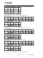
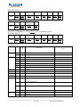
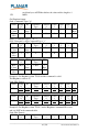
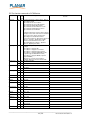
Planar PS-Series RS232 Protocol
(Applies to PS4652, PS5552, and PS6552 models only)
1 Introduction
This document describes the hardware interface spec and software protocols of RS232 interface
communication between Commercial Display and PC or other control unit with RS232 protocol.
1. Protocol 1, with ID
This set protocol allow user to assign the ID in the command to control the specify ID monitor
2. Protocol 2, without ID
The set protocol is best for single display control
Both sets protocol contain three sections command:
Set-Function
Get-Function
Remote control pass-through mode
※In below document, “PC” will represents all the control units that can sent or receive the RS232
protocol command.
2 Description
2.1
Hardware specification
LCD communication port in the rear side
(1) Connector type: DSUB 9 Pin Male
(2) Pin Assignment
Male DSUB 9Pin
(outside view)
Pin #
1
2
Signal
NC
RXD
3
TXD
Remark
Input to LCD
Monitor
Output from LCD
Monitor
4
NC
5
GND
6
NC
7
NC
8
NC
9
NC
frame GND
*Use of crossover (null modem) cable
required for use with PC
2.2
Communication Setting
- Baud Rate Select: 9600bps (fixed)
- Data bits:
8bits (fixed)
- Parity:
None (fixed)
________________________________________________________________
1 / 26
Document 020-1241-00 Rev A
- Stop Bits:
1(fixed)
2.3 Command Message Reference
PC sends to Monitor command packet followed by “CR”. Every time PC sends control command to
the Monitor, the Monitor shall response as follows:
1. If the message is receives correctly it will send “+” (02Bh) followed by “CR” (00Dh)
2. If the message is receives incorrectly it will send “-” (02Dh) followed by “CR” (00Dh)
3 Protocol 1: with ID
3.1 Command Description
Length:
TV ID
Command
Type
Command:
Value[1~3]:
CR
Total Byte of Message excluding “CR”
Identification for each of TV
Identify command type,
“s” (0x73h) : Set Command
“g” (0x67h) : Get Command
“r” (0x72h) : Reply Command
“p” (0x70h) : RCU Pass-through
“+” (0x2Bh) : Valid command Reply
“-“ (0x2Dh) : Invalid command Reply
Function command code: One byte ASCII code
Three bytes ASCII that defines the value
0x0D
3.2
Set-Function Listing
The PC can control the LCD Monitor for specific actions. The Set-Function command allows you to
control the LCD monitor behavior in a remote sit through the RS232 port. The Set-Function packet
format consists of 11 bytes.
Set-Function description:
Length:
Total Byte of Message excluding “CR”
TV ID
Identification for each of TV
If we want to set all TV settings, TV ID can use “99” to achieve, and it
will not have Reply command on this function.
Command
Identify command type,
Type
“s” (0x73h) : Set Command
Command:
Function command code: One byte ASCII code
Value[1~3]: Three bytes ASCII that defines the value
CR
0x0D
Set-Function format
Send: (Command Type=”s”)
ID
Command Comman Value Value Value CR
Name Lengt
h
Type
d
1
2
3
Byte 1 Byte
2
1 Byte
1 Byte
1 Byte 1 Byte 1 Byte
1
Count
Byte
Byte
Bytes
1
2~3
4
5
6
7
8
9
________________________________________________________________
2 / 26
Document 020-1241-00 Rev A
order
Reply: (Command Type=”+” or “-”)
ID
Command
Name Lengt
h
Type
Byte 1 Byte
2
1 Byte
Count
Byte
Bytes
1
2~3
4
order
CR
1
Byte
5
Example1: Set Brightness as 76 for TV-02 and this command is valid
Send (Hex Format)
Name Lengt
ID
Command Comman Value Value
h
Type
d
1
2
Hex
0x38 0x30
0x73
0x24
0x30
0x37
0x32
Reply (Hex Format)
Name Lengt
ID
Command
CR
h
Type
Hex
0x34 0x30
0x2B
0x0
0x32
D
Value
3
0x36
Example2: Set Brightness as 176 for TV-02 and this command is NOT valid
Send (Hex Format)
ID
Command Comman Value Value Value
Name Lengt
h
Type
d
1
2
3
Hex
0x38 0x30
0x73
0x24
0x31
0x37
0x36
0x32
Reply (Hex Format)
Name Lengt
ID
Command
CR
h
Type
Hex
0x34 0x30
0x2D
0x0
0x32
D
Example3: Set Tint as 32 for TV-03 and this command is valid
Send (Hex Format)
Name Lengt
ID
Command Comman Value Value Value
h
Type
d
1
2
3
Hex
0x38 0x30
0x73
0x27
0x30
0x33
0x32
0x33
Reply (Hex Format)
Name Lengt
ID
Command
CR
h
Type
Hex
0x34 0x30
0x2B
0x0
0x33
D
CR
0x0
D
CR
0x0
D
CR
0x0
D
Example4: Set Tint as 75 for TV-03 and this command is NOT valid
________________________________________________________________
3 / 26
Document 020-1241-00 Rev A
Send (Hex Format)
Name Lengt
ID
h
Hex
0x38 0x30
0x33
Reply (Hex Format)
Name Lengt
ID
h
Hex
0x34 0x30
0x33
Command
Type
0x73
Comman
d
0x27
Command
Type
0x2D
CR
Value
1
0x30
Value
2
0x37
Power
Len
8
0x0
D
Value
3
0x36
CR
0x0
D
Value Range
(ASCII Bytes)
Cmd
Code
(Hex)
21
CR
0x0
D
Example5: Set Brightness as 76 for all TV and this command is valid
Send (Hex Format)
Name Lengt
ID
Command Comman Value Value
h
Type
d
1
2
Hex
0x38 0x39
0x73
0x24
0x30
0x37
0x39
No Reply.
Set-function table
Set Function
Value
3
0x35
Remark
000: Standby
001: On
Video Source
8
22
000 : VGA
001 : HDMI1
004 : YPbPr
006 : DVI
007 : DisplayPort
009 : Multi-Media
Contrast
8
23
000 ~ 100
Brightness
8
24
000 ~ 100
Sharpness
8
25
000 ~ 020
Picture Reset
8
26
Aspect Ratio
8
31
000: Full (Video) / Full 2 (PC)
001: 4:3 (Video) /Real (PC)
002: Wide Zoom (Video) / Full1 (PC)
003: Zoom (Video)
Language
8
32
000: English
001: Français
________________________________________________________________
4 / 26
Document 020-1241-00 Rev A
002: Español
繁中
004: 简中
003:
ê
005: Portugu s
006: German
007: Dutch
008: Polish
009: Russia
Sound Mode
8
33
000: Dynamic
001: Standard
002: Custom
Volume
8
35
000 ~ 100
Mute
8
36
000: Off
001: On
Treble
8
37
000~100
OSD value=RS232 value-50
Bass
8
38
000~100
OSD value=RS232 value-50
Balance
8
39
000~100
OSD value=RS232 value-50
Surround
8
3A
000: Off
001: On
Sound Reset
8
3B
Monitor ID
8
3D
001 ~ 098
IR Control
8
42
000: Disable
All the buttons at the remote controller
have no function
001: Enable
002: Passthrough Master
Note: To set Pass through, the command must use the "With ID
protocol", and the ID should between "01"~"98".
________________________________________________________________
5 / 26
Document 020-1241-00 Rev A
003: Passthrough Slave
Note1: To set Pass through, the command must use the "With
ID protocol", and the ID should between "01"~"98".
Note2: The monitor will not response to any RS232 command if
it is at Passthrough Slave mode
Button&IR
Control
8
43
000: Disable
All the buttons at both keypad board
and remote controller have no
function.
001: Enable
Button Control
8
45
000: Disable
All the buttons at the keypad board
have no function
001: Enable
Image
Retention
8
47
OSD Info Box
8
5B
All Reset
8
7E
Picture Mode
8
81
000: Off
001: On
000: Off
001: On
000: Standard
001: Vivid
002: Cinema
003: Custom
Chroma (Color)
8
82
000 ~ 050
Phase (Tint)
8
83
000 ~ 050
Backlight
8
84
000 ~ 100
Adaptive
Contrast
8
85
000: Off
Color Temp
8
001: On
86
000: Cool
001: Neutral
002: Warm
003: Custom
Audio Source
8
88
000: Audio1
002: HDMI or HDMI1
004: DisplayPort
006: Multi-Media
Speaker
8
89
000: Internal
002: Lineout
________________________________________________________________
6 / 26
Document 020-1241-00 Rev A
PAP Enable
8
8A
000: Off
001: PIP
002: PBP
PAP Size
8
8D
When PAP=PIP
000: Small
001: Large
When PAP=PBP
000 ~ 014
PIP Position
8
8E
000: Upper Left
001: Upper Right
002: Lower Left
003: Lower Right
Auto
Adjustment
Execute
8
8F
VGA Clock
frequency
8
90
000 ~ 100
VGA Phase
8
91
000 ~ 031
VGA H.Position
8
92
000 ~ 060
VGA V.Position
8
93
000 ~ 060
Ambient Light
Sensor
8
94
000: Off
Auto Search
8
For VGA only, execute auto
adjustment.
001: On
96
000: Off
001: On
Over Scan
8
97
000: Off
001: On
002: Auto
RTC Year
8
98
000 ~ 099
Ex: value=012 means Year 2012
If the setting is illegal (Ex: Year 2013
doesn't have the date Feb/29), return
"Invalid Command Reply".
________________________________________________________________
7 / 26
Document 020-1241-00 Rev A
RTC Month
8
99
001 ~ 012
Ex: value=001 means January
If the setting is illegal (Ex: February
doesn't have the date Feb/31), return
"Invalid Command Reply".
RTC Day
8
9A
001 ~ 031
If the setting is illegal (Ex: Day31
doesn't exist in April), return "Invalid
Command Reply".
RTC Hour
8
9B
000 ~ 023
RTC Minute
8
9C
000 ~ 059
OSD Rotation
8
9F
000: Landscape
001: Portrait
H Monitor
8
A4
001 ~ 010
V Monitor
8
A5
001 ~ 010
H Position
8
A6
001 ~ 010
V Position
8
A7
001 ~ 010
Frame Comp.
8
A8
000: Off
001: On
Power Save
8
A9
000: Off
001: Low
002: High
Auto
Adjustment
8
AA
000: Off
Display Wall
LED
8
Display Wall
Power On
Delay
8
AF
000: Off
PAP Active
Picture
8
BE
000: Main(For PIP), Left(For PBP)
001: On
AE
000: Off
001: On
001: On
001: Sub(For PIP), Right(For PBP)
________________________________________________________________
8 / 26
Document 020-1241-00 Rev A
On/Off Timer
14
E0
Byte1~Byte9
(1) Byte1: Decide which Timer is selected, and its
enable/disable setting.
Byte1[3:0]=0x1~0x07. There are totally 7 Timers, this value is
used to decide which Timer is selected.
Byte1[7]: Reserved, should be 0.
Byte1[6]: The Timer is enable or not. Byte1[6]=1 means enable.
Byte1[5]: The On Timer is enable or not. Byte1[5]=1 means
enable.
Byte1[4]: The Off Timer is enable or not. Byte1[4]=1 means
enable.
(2) Byte2: The Day of the On/Off Timer. bit0 for Sunday, bit1 for
Monday, bit2 for Tuesday, bit3 for Wednesday, bit4 for
Thursday, bit5 for Friday, bit6 for Saturday, bit7 for Everday.
(3) Byte3: The Hour of the On Timer. Byte3=0x00~0x17.
(4) Byte4: The Minute of the On Timer. Byte4=0x00~0x3B.
(5) Byte5: The Hour of the Off Timer. Byte5=0x00~0x17.
(6) Byte6: The Minute of the Off Timer. Byte6=0x00~0x3B.
(7) Byte7: Select the Video Source.
0x00=VGA, 0x01=HDMI1, 0x02=HDMI2, 0x03=AV,
0x04=YPbPr, 0x05=S-Video, 0x06=DVI, 0x07=DisplayPort,
0x08=SDI, 0x09=Multi-Media. 0xFF=Default. Other values are
reserved.
(8) Byte8~9 are reserved, and should be 0x00.
Note: Some of the Video Sources are
not supported if the model doesn't
have this feature..
Ex: Byte1=0x01 means the Timer no.1
is selected and disable.
Ex: Byte1=0x41 means the Timer no.1
is select and enable, and its both On
and Off Timers are disable.
Ex: Byte1=0x61 means the Timer no.1
is select and enable, and its On Timer
is enable, Off Timer is disable.
Ex: Byte1=0x71 means the Timer no.1
is select and enable, and its both On
and Off Timers are enable.
Ex: Byte1=0x53 means the Timer no.3
is select and enable, and its On Timer
is disable, Off Timer is enable.
Ex: Byte2=0x02 means the Timer is on
Monday.
Ex: Byte3=0x08, Byte4=0x1E means
the On Timer is at 8:30.
Ex: Byte5=0x17, Byte6=0x00 means
the Off Timer is at 23:00.
Ex: Byte7=0x00 means the selected
Video Source is VGA.
8
Change
Protocol
FF
001: Change protocol to Factory Protocol.
002: Change protocol to Gprobe Protocol.
Other values are reserved.
3.3 Get-Function Listing
The PC can interrogate the LCD Monitor for specific information. The Get-Function packet format
consists of 5 bytes which is similar to the Set-Function packet structure. Note that the “Value” byte is
always = 00.
Get-Function description:
Length:
Total Byte of Message excluding “CR”
TV ID
Identification for each of TV
Command
Identify command type,
Type
“g” (0x67h) : Get Command
Command:
Function command code: One byte ASCII code
Value[1~3]: Three bytes ASCII that defines the value
NOTE: to get backlight senor, thermal sensor, and ambient sensor
________________________________________________________________
9 / 26
Document 020-1241-00 Rev A
CR
need four bytes ASCII that defines the value and the length is 9.
0x0D
Get-Function format
Send: (Command Type=”g”)
Name Lengt
ID
Command Comman Value Value Value CR
h
Type
d
1
2
3
Byte 1 Byte
2
1 Byte
1 Byte
1 Byte 1 Byte 1 Byte
1
Count
Byte
Byte
Bytes
1
2~3
4
5
6
7
8
9
order
Reply: (Command Type=”r” or “-”)
If the Command is valid, Command Type =”r”
Name Lengt
ID
Command Comman Value Value Value CR
h
Type
d
1
2
3
Byte 1 Byte
2
1 Byte
1 Byte
1 Byte 1 Byte 1 Byte
1
Count
Byte
Byte
Bytes
1
2~3
4
5
6
7
8
9
order
If the Command is Not valid, Command Type=”-“
Name Lengt
ID
Command
CR
h
Type
Byte 1 Byte
2
1 Byte
1
Count
Byte
Byte
Bytes
1
2~3
4
5
order
Example1: Get Brightness from TV-05 and this command is valid.
The Brightness value is 67.
Send (Hex Format)
ID
Command Comman Value Value
Name Lengt
h
Type
d
1
2
Hex
0x38 0x30
0x67
0x62
0x30
0x30
0x35
Reply(Hex Format)
Name Lengt
ID
Command Comman Value Value
h
Type
d
1
2
Hex
0x38 0x30
0x72
0x62
0x30
0x36
0x35
Value
3
0x30
Value
3
0x37
CR
0x0
D
CR
0x0
D
Example2: Get Brightness from TV-05 , but the Brightness command ID is error
and it is NOT in the command table.
Send (Hex Format)
Name Lengt
ID
Command Comman Value Value Value CR
h
Type
d
1
2
3
________________________________________________________________
10 / 26
Document 020-1241-00 Rev A
Hex
0x38
0x30
0x35
Reply (Hex Format)
Name Lengt
ID
h
Hex
0x34 0x30
0x35
0x67
Command
Type
0x2D
0XD3
0x30
0x30
0x30
0x0
D
Value
2
0x30
Value
3
0x30
CR
Value
2
0x33
Value
3
0x32
CR
0x0
D
Example3: Get Tint from TV-0007 and this command is valid.
The Tint value is 32.
Send (Hex Format)
Name Lengt
ID
Command Comman Value
h
Type
d
1
Hex
0x38 0x30
0x67
0X65
0x30
0x37
Reply (Hex Format)
Name Lengt
ID
Command Comman Value
h
Type
d
1
Hex
0x38 0x30
0x72
0x65
0x30
0x37
0x0
D
CR
0x0
D
Example4: Get Tint from TV-07 , but the Brightness command ID is error and it is NOT in the
command table.
Send (Hex Format)
ID
Command Comman Value Value Value CR
Name Lengt
h
Type
d
1
2
3
Hex
0x38 0x30
0x67
0XD7
0x30
0x30
0x30 0x0
0x37
D
Reply (Hex Format)
Name Lengt
ID
Command
CR
h
Type
Hex
0x34 0x30
0x2D
0x0
0x37
D
Example5 Get backlight sensor from TV-0007 and this command is valid.
The lux value is 1786 (ASCII code).
Send (Hex Format)
Name Lengt
ID
Command Comman Value Value Value
h
Type
d
1
2
3
Hex
0x39 0x30
0x67
0X6F
0x30
0x30
0x30
0x37
Reply (Hex Format)
Name Lengt
ID
Command Comman Value Value Value
h
Type
d
1
2
3
Hex
0x39 0x30
0x72
0X6F
0x31
0x37
0x38
Value
4
0x30
Value
3
0x36
________________________________________________________________
11 / 26
Document 020-1241-00 Rev A
CR
0x0
D
CR
0x0
0x37
D
Example6 Get ambient sensor from TV-0007 and this command is valid.
The lux value is 1568 (ASCII code).
Send (Hex Format)
ID
Command Comman Value Value Value
Name Lengt
h
Type
d
1
2
3
Hex
0x39 0x30
0x67
0X70
0x30
0x30
0x30
Value
4
0x30
CR
0x0
D
0x37
Reply (Hex Format)
Name Lengt
ID
h
Hex
0x39 0x30
Command
Type
0x72
Comman
d
0X70
Value
1
0x31
Value
2
0x35
Value
3
0x36
Value
4
0x38
CR
0x0
D
0x37
Example7 Get thermal sensor from TV-0007 and this command is valid.
The value is +075 degree (ASCII code). NOTE: positive degree is “+”ASCII code and negative degree
is “-”ASCII code.
Send (Hex Format)
Name Lengt
ID
Command Comman Value Value Value Value CR
h
Type
d
1
2
3
4
Hex
0x39 0x30
0x67
0X71
0x30
0x30
0x30
0x30 0x0
D
0x37
Reply (Hex Format)
ID
Name Lengt
h
Hex
0x39 0x30
Command
Type
0x72
Comman
d
0X71
Value
1
0x2B
Value
2
0x30
Value
3
0x37
Value
4
0x35
CR
0x37
Example8 Get Running Hours from TV-0007 and this command is valid.
The value is 21,356 hours (ASCII code).
Send (Hex Format)
Name Lengt
ID
Command Comman Value Value Value
h
Type
d
1
2
3
Hex
0x3A 0x30
0x67
0X76
0x30
0x30
0x30
Value
4
0x30
Value
5
0x30
Value
4
Value
5
0x0
D
CR
0x0
D
0x37
Reply (Hex Format)
Name Lengt
ID
h
Command
Type
Comman
d
Value
1
Value
2
Value
3
________________________________________________________________
12 / 26
Document 020-1241-00 Rev A
CR
Hex
0x3A
0x30
0x72
0X76
0x32
0x31
0x33
0x35
0x37
________________________________________________________________
13 / 26
Document 020-1241-00 Rev A
0x36
0x0
D
PC Get-function command to LCD Monitor
Get Function
Model Info
Len Cmd
Code
(Hex)
20
20
Value Range (ASCII Bytes)
Remark
(1) Input value: Byte1 - Byte2 - Byte3…Byte15
Byte2~Byte11=0x00
Byte1=0x01: Get Customer Name
Byte1=0x02: Get Customer Model Name
Byte1=0x03: Get Qisda Model Name
Byte1=0x04: Get Scaler Firmware Version
Byte1=0x05: Get LAN Firmware Version
Byte1=0x06: Get Serial Number
(2) Return value: Byte1 - Byte2 - Byte3…Byte15
The Byte1 value at the return value should be the
same as the value of Byte1 at input value.
Byte2~Byte15 should be ASCII format.
Ex: If Customer=Generic, Byte1=0x01, Byte2='G',
Byte3='e',...Byte8='c', Byte9~Byte11=0x00.
Ex: If the Scaler Firmware Version=1.02,
Byte1=0x03, Byte2='1', Byte3='.', Byte4='0',
Byte5='2', Byte6~Byte11=0x00.
Capability
8
21
Signal Status
8
22
Return value: Byte1 - Byte2 - Byte3
(1) Byte1
bit0 of Byte1=1: Support SDI
bit1 of Byte1=1: Support Touch feature
bit2 of Byte1=1: Support Internal speaker
bit3 of Byte1=1: Support Multi-Media module
(only STB supports Multi-Media module)
bit4 of Byte1=1: Support HDMI2 (only STA
supports HDMI2)
Other bit are reserved, and should be 0.
(2) Byte2~Byte3: Reserved, should be 0x00.
000: Signal unstable
Signal Format
8
23
000: PC
001: Signal stable (Active Sync exists)
001: Video
AV Timing
8
24
000: NTSC
001: PAL
Treble
8
37
000~100
OSD value=RS232 value-50
Bass
8
38
000~100
OSD value=RS232 value-50
Balance
8
39
000~100
OSD value=RS232 value-50
Surround
8
3A
000: Off
001: On
OSD Info Box
8
5D
000: Off
001: On
Contrast
8
61
000 ~ 100
Brightness
8
62
000 ~ 100
Sharpness
8
63
000 ~ 020
Sound Mode
8
65
000: Dynamic
001: Standard
002: Custom
Volume
8
66
000 ~ 100
________________________________________________________________
14 / 26
Document 020-1241-00 Rev A
Mute
8
67
000: Off
001: On
IR Control
8
68
000: Disable
All the buttons at the remote controller have no function
001: Enable
002: Passthrough Master
Note: To set Pass through, the command must
use the "With ID protocal", and the ID should
between "01"~"98".
003: Passthrough Slave
Note1: To set Pass through, the command must
use the "With ID protocal", and the ID should
between "01"~"98".
Note2: The monitor will not response to any
RS232 command if it is at Passthrough Slave
mode
Button&IR
Control
8
69
000: Disable
All the buttons at both keypad board and remote controller
have no function.
001: Enable
Video Source
8
6A
000 : VGA
If PIP or PBP=On, the return value is the source at active
window.
001 : HDMI1
004 : YPbPr
006 : DVI
007 : DisplayPort
008 : SDI
Option, not support if the platform doesn't have this feature.
009 : Multi-Media
Option, not support if the platform doesn't have this feature.
Power
8
6C
000: Standby
5V
8
6D
~050
value=049 means 4.9V
12V
8
6E
~120
value=122 means 12.2V
Ambient Sensor 10
Value
70
00000 ~ 2000
Ex: If the value is 500, the return value should be:
Byte1=0x30, Byte2=0x35, Byte3=0x30, Byte4=0x30,
Byte5=0x30.
Thermal Sensor 10
Value
71
(1) Input value: Byte1-Byte2-...Byte5
(a) Byte1=0x01: Get the thermal sensor value
from main board
0x02: Get the thermal sensor value
from keypad board
(b) Byte2~Byte5 are reserved, should b 0x00
001: On
℃
Ex: If the temperature 5 is from main board, the return value
should be: Byte1=0x01, Byte2=0x2B, Byte3=0x30,
Byte4=0x30, Byte5=0x35.
(2) Return value: Byte1-Byte2-...Byte5
(a) Byte1=0x01: The thermal sensor value is from
main board
Ex: If the temperature -15 is from keypad board, the return
0x02: The thermal sensor value is rom
value should be: Byte1=0x02, Byte2=0x2D, Byte3=0x30,
kaypad board
(b) Byte2: If the thermal value is >=0, Byte2='+' Byte4=0x31, Byte5=0x35.
(0x2B)
If the thermal value is <0, Byte2='-'
(0x2D)
(c) Byte3~Byte5: The absolute value of the
temperature, in ASCII format.
000: Off
℃
Image
Retention
8
Button Control
8
72
001: On
73
000: Disable
All the buttons at the keypad board have no function
________________________________________________________________
15 / 26
Document 020-1241-00 Rev A
001: Enable
Monitor ID
8
75
001 ~ 098
Operation Time 10
76
00000 ~ 99999
Aspect Ratio
77
000: Full (Video) / Full 2 (PC)
8
unit is hour
001: 4:3 (Video) /Real (PC)
002: Wide Zoom (Video) / Full1 (PC)
003: Zoom (Video)
Language
8
78
000: English
001: Français
002: Español
繁中
004: 简中
003:
ê
005: Portugu s
006: German
007: Dutch
008: Polish
009: Russia
Display Wall
LED
8
AE 000: OFF
001: ON
Display Wall
8
Power On Delay
AF
Picture Mode
B1
8
000: OFF
001: ON
000: Standard
001: Vivid
002: Cinema
003: Custom
Chroma (Color)
8
B2
000 ~ 050
Phase (Tint)
8
B3
000 ~ 050
Backlight
8
B4
000 ~ 100
Adaptive
Contrast
8
B5
000: Off
Color Temp
8
001: On
B6
000: Cool
001: Neutral
002: Warm
003: Custom
Audio Source
8
88
000: Audio1
002: HDMI or HDMI1
004: DisplayPort
006: Multi-Media
Speaker
8
B9
000: Internal
PAP Enable
8
BA 000: Off
002: Lineout
________________________________________________________________
16 / 26
Document 020-1241-00 Rev A
001: PIP
002: PBP
PAP Size
8
BD When PAP=PIP
000: Small
001: Large
When PAP=PBP
000 ~ 014
PAP Active
Picture
8
PIP Position
8
BE 000: Main(For PIP), Left(For PBP)
001: Sub(For PIP), Right(For PBP)
BF
000: Upper Left
001: Upper Right
002: Lower Left
003: Lower Right
VGA Clock
frequency
VGA Phase
8
C0
000 ~ 100
8
C1
000 ~ 031
VGA H.Position
8
C2
000 ~ 060
VGA V.Position
8
C3
000 ~ 060
Ambient Light
Sensor
8
C4
000: Off
Auto Search
8
C6
000: Off
For VGA only.
For VGA only.
001: On
001: On
Over Scan
8
C7
000: Off
001: On
002: Auto
RTC Year
8
C8
000 ~ 099
RTC Month
8
C9
001 ~ 012
RTC Day
8
CA 001 ~ 031
If the RTC is not enable, return "Invalid Command Reply"
RTC Hour
8
CB 000 ~ 023
If the RTC is not enable, return "Invalid Command Reply"
RTC Minute
8
CC 000 ~ 059
If the RTC is not enable, return "Invalid Command Reply"
OSD Rotation
8
CF 000: Landscape
H Monitor
8
D4
001 ~ 010
V Monitor
8
D5
001 ~ 010
H Position
8
D6
001 ~ 010
V Position
8
D7
001 ~ 010
Frame Comp.
8
D8
000: Off
Ex: value=012 means Year 2012
If the RTC is not enable, return "Invalid Command Reply"
Ex: value=001 means January
If the RTC is not enable, return "Invalid Command Reply"
001: Portrait
001: On
Power Save
8
D9
000: Off
001: Low
________________________________________________________________
17 / 26
Document 020-1241-00 Rev A
002: High
Auto
Adjustment
8
On/Off Timer
14
DA 000: Off
001: On
E0
Input value: Byte1 - Byte2 - Byte3…Byte9
(1) Byte1[3:0]: The Number of the On/Off Timer.
There are totally 7 On/Off Timers, and this byte is
used to selected which timer is going to be
accessed.
(2) Byte1[7:4] is reserved, should be 0.
(3) Byte2~9 are reserverd, should be 0x00.
Return value: Byte1 - Byte2 - Byte3…Byte9
(1) Byte1[3:0]: Should retuen the same value as
Byte1 at Input value.
Byte1[7]: Reserved, should be 0.
Byte1[6]: The Timer is enable or not. Byte1[6]=1
means enable.
Byte1[5]: The On Timer is enable or not.
Byte1[5]=1 means enable.
Byte1[4]: The Off Timer is enable or not.
Byte1[4]=1 means enable.
(2) Byte2: The Day of the On/Off Timer. bit0 for
Sunday, bit1 for Monday, bit2 for Tuesday, bit3 for
Wednesday, bit4 for Thursday, bit5 for Friday, bit6
for Saturday, bit7 for Everday.
(3) Byte3: The Hour of the On Timer.
Byte3=0x00~0x17.
(4) Byte4: The Minute of the On Timer.
Byte4=0x00~0x3B.
(5) Byte5: The Hour of the Off Timer.
Byte5=0x00~0x17.
(6) Byte6: The Minute of the Off Timer.
Byte6=0x00~0x3B.
(7) Byte7: Select the Video Source.
0x00=VGA, 0x01=HDMI1, 0x02=HDMI2,
0x03=AV, 0x04=YPbPr, 0x05=S-Video,
0x06=DVI, 0x07=DisplayPort, 0x08=SDI,
0x09=Multi-Media. 0xFF=Default. Other values
are reserved.
(8) Byte8~9 are reserved, and should be 0x00.
See the return value examples below:
Ex: Byte1=0x01 means the Timer no.1 is selected and
disable.
Ex: Byte1=0x41 means the Timer no.1 is select and enable,
and its both On and Off Timers are disable.
Ex: Byte1=0x61 means the Timer no.1 is select and enable,
and its On Timer is enable, Off Timer is disable.
Ex: Byte1=0x71 means the Timer no.1 is select and enable,
and its both On and Off Timers are enable.
Ex: Byte1=0x53 means the Timer no.3 is select and enable,
and its On Timer is disable, Off Timer is enable.
Ex: Byte2=0x02 means the Timer is on Monday.
Ex: Byte3=0x08, Byte4=0x1E means the On Timer is at 8:30.
Ex: Byte5=0x17, Byte6=0x00 means the Off Timer is at
23:00.
Ex: Byte7=0x00 means the selected Video Source is VGA.
________________________________________________________________
18 / 26
Document 020-1241-00 Rev A
Input Value: Byte1 - Byte2 - Byte3…Byte9
(1) Byte1=0x00: IP Setup Mode
Byte1=0x01: IP Address
Byte1=0x02: Get Subnet Mask
Byte1=0x03: Default Gateway
Byte1=0x04: Primary DNS
Byte1=0x05: Secondary DNS
Byte1=0x06: MAC Address
(2) Byte2~9 are reserved, should be 0x00.
Network Setting 14
E1
Return value: Byte1 - Byte2 - Byte3…Byte9
The Byte1 at the return value should be the same
as the value of Byte1 at Input value.
Byte2~Byte15 should be hex value format
(1) If Byte1=0x00(IP Setup Mode) at Input value,
the return value should be
Ex: Subnet Mask=255.255.255.0, the return value:
Byte1=0x00
Byte2=0x00: Manual
Byte1=0x02, Byte2=0xFF, Byte3=0xFF, Byte4=0xFF,
0x01: DHCP
Byte5=0x00, Byte6~9=0x00.
Byte3~9 are reserved, should be 0x00.
(2) If Byte1=0x01(IP Address) at Input value, the
return value should be
Ex: IP address=169.254.81.38
Byte1=0x01 (same as Byte1 at Input value)
Byte2=0xA9 (=169), Byte3=0xFE (=254),
Byte4=0x51(=81), Byte5=0x26 (=38)
Byte6~9 are reserved, should be 0x00.
(3) If Byte1=0x02~0x05 at Input value, refer to (2)
(4) If Byte1=0x06(MAC Address) at Input value,
the return value should be
Ex: MAC address=00:22:64:7E:2C:82
Byte1=0x06 (same as Byte1 at Input value)
Byte2=0x00, Byte3=0x22, Byte4=0x64,
Byte5=0x7E, Byte6=0x2C, Byte7=0x82
Byte8~9 are reserved, should be 0x00.
4 Protocol 2 : without ID
4.1
Set function listing
The PC can control the LCD Monitor for specific actions. The Set-Function command allows you to
control the LCD monitor behavior in a remote sit through the RS232 port. The Set-Function packet
format consists of 5 bytes. Note that the “Value” byte is always = 00.
Set-Function description:
Length:
Total bytes of message = 5 ASCII (35H) excluding “CR”
Command:
Function command code: One byte ASCII code
Value[1~3]: Three bytes ASCII that defines the value
Set-Function format:
Name
Length
Byte Count 1 Byte
Bytes order
1
CR
Command Value1 Value2 Value3
1 Byte
1 Byte 1 Byte 1 Byte 1 Byte
2
3
4
5
6
________________________________________________________________
19 / 26
Document 020-1241-00 Rev A
All Set-Function from PC to Monitor (ASCII)
Name
Length Command Value1 Value2 Value3 CR
Byte Count
5
1 Byte
1 Byte 1 Byte 1 Byte 00D
Bytes order
1
2
3
4
5
6
Example: Set Mute-ON command (ASCII)
Name
Length Command Value1 Value2 Value3 CR
Byte Count
5
6
0
0
0
00D
Bytes order
1
2
3
4
5
6
Example: Set Mute-OFF command (ASCII)
Name
Length Command Value1 Value2 Value3 CR
Byte Count
5
6
0
0
1
00D
Bytes order
1
2
3
4
5
6
LCD Monitor will send “+” (02Bh) and “CR” bytes to PC after receiving a valid command.
LCD Monitor will send “-” (02Dh) and “CR” bytes to PC if the command is not valid.
Value Range: Three bytes ASCII value range
Command Function command code in ASCII
Code:
set command table
Get Function
Model Info
Len Cmd
Code
(Hex)
17
20
Value Range (ASCII Bytes)
Remark
(1) Input value: Byte1 - Byte2 - Byte3…Byte15
Byte2~Byte11=0x00
Byte1=0x01: Get Customer Name
Byte1=0x02: Get Customer Model Name
Byte1=0x03: Get Qisda Model Name
Byte1=0x04: Get Scaler Firmware Version
Byte1=0x05: Get LAN Firmware Version
Byte1=0x06: Get Serial Number
(2) Return value: Byte1 - Byte2 - Byte3…Byte15
The Byte1 value at the return value should be the
same as the value of Byte1 at input value.
Byte2~Byte15 should be ASCII format.
Ex: If Customer=Generic, Byte1=0x01, Byte2='G',
Byte3='e',...Byte8='c', Byte9~Byte11=0x00.
Ex: If the Scaler Firmware Version=1.02,
Byte1=0x03, Byte2='1', Byte3='.', Byte4='0',
Byte5='2', Byte6~Byte11=0x00.
________________________________________________________________
20 / 26
Document 020-1241-00 Rev A
Capability
5
21
Signal Status
5
22
Return value: Byte1 - Byte2 - Byte3
(1) Byte1
bit0 of Byte1=1: Support SDI
bit1 of Byte1=1: Support Touch feature
bit2 of Byte1=1: Support Internal speaker
bit3 of Byte1=1: Support Multi-Media module
(only STB supports Multi-Media module)
bit4 of Byte1=1: Support HDMI2 (only STA
supports HDMI2)
Other bit are reserved, and should be 0.
(2) Byte2~Byte3: Reserved, should be 0x00.
000: Signal unstable
001: Signal stable (Active Sync exists)
Signal Format
5
23
000: PC
001: Video
AV Timing
5
24
000: NTSC
001: PAL
Treble
5
37
000~100
OSD value=RS232 value-50
Bass
5
38
000~100
OSD value=RS232 value-50
Balance
5
39
000~100
OSD value=RS232 value-50
Surround
5
3A
000: Off
OSD Info Box
5
5D
000: Off
001: On
001: On
Contrast
5
61
000 ~ 100
Brightness
5
62
000 ~ 100
Sharpness
5
63
000 ~ 020
Sound Mode
5
65
000: Dynamic
001: Standard
002: Custom
Volume
5
66
000 ~ 100
Mute
5
67
000: Off
001: On
IR Control
5
68
000: Disable
All the buttons at the remote controller have no function
001: Enable
002: Passthrough Master
Note: To set Pass through, the command must
use the "With ID protocal", and the ID should
between "01"~"98".
003: Passthrough Slave
Note1: To set Pass through, the command must
use the "With ID protocal", and the ID should
between "01"~"98".
Note2: The monitor will not response to any
RS232 command if it is at Passthrough Slave
mode
Button&IR
Control
5
69
000: Disable
All the buttons at both keypad board and remote controller
have no function.
001: Enable
________________________________________________________________
21 / 26
Document 020-1241-00 Rev A
Video Source
5
6A
000 : VGA
If PIP or PBP=On, the return value is the source at active
window.
001 : HDMI1
004 : YPbPr
006 : DVI
007 : DisplayPort
009 : Multi-Media
Power
5
6C
000: Standby
001: On
5V
5
6D
~050
12V
5
6E
~120
value=122 means 12.2V
Ambient Sensor 7
Value
70
00000 ~ 2000
Ex: If the value is 500, the return value should be:
Byte1=0x30, Byte2=0x35, Byte3=0x30, Byte4=0x30,
Byte5=0x30.
Thermal Sensor 7
Value
71
(1) Input value: Byte1-Byte2-...Byte5
(a) Byte1=0x01: Get the thermal sensor value
from main board
0x02: Get the thermal sensor value
from keypad board
(b) Byte2~Byte5 are reserved, should b 0x00
value=049 means 4.9V
℃
Ex: If the temperature 5 is from main board, the return value
should be: Byte1=0x01, Byte2=0x2B, Byte3=0x30,
Byte4=0x30, Byte5=0x35.
(2) Return value: Byte1-Byte2-...Byte5
(a) Byte1=0x01: The thermal sensor value is from
main board
Ex: If the temperature -15 is from keypad board, the return
0x02: The thermal sensor value is rom
value
should be: Byte1=0x02, Byte2=0x2D, Byte3=0x30,
kaypad board
(b) Byte2: If the thermal value is >=0, Byte2='+' Byte4=0x31, Byte5=0x35.
(0x2B)
If the thermal value is <0, Byte2='-'
(0x2D)
(c) Byte3~Byte5: The absolute value of the
temperature, in ASCII format.
000: Off
℃
Image
Retention
5
Button Control
5
72
001: On
73
000: Disable
All the buttons at the keypad board have no function
001: Enable
Monitor ID
5
75
001 ~ 098
Operation Time
7
76
00000 ~ 99999
Aspect Ratio
5
77
000: Full (Video) / Full 2 (PC)
unit is hour
001: 4:3 (Video) /Real (PC)
002: Wide Zoom (Video) / Full1 (PC)
003: Zoom (Video)
Language
5
78
000: English
001: Français
002: Español
繁中
004: 简中
003:
ê
005: Portugu s
006: German
007: Dutch
________________________________________________________________
22 / 26
Document 020-1241-00 Rev A
008: Polish
009: Russia
Display Wall
LED
5
AE 000: OFF
001: ON
Display Wall
5
Power On Delay
AF
Picture Mode
B1
5
000: OFF
001: ON
000: Standard
001: Vivid
002: Cinema
003: Custom
Chroma (Color)
5
B2
000 ~ 050
Phase (Tint)
5
B3
000 ~ 050
Backlight
5
B4
000 ~ 100
Adaptive
Contrast
5
B5
000: Off
Color Temp
5
B6
000: Cool
001: On
001: Neutral
002: Warm
003: Custom
Audio Source
5
88
000: Audio1
002: HDMI or HDMI1
004: DisplayPort
006: Multi-Media
Speaker
5
B9
000: Internal
002: Lineout
PAP Enable
5
BA 000: Off
001: PIP
002: PBP
PAP Size
5
BD When PAP=PIP
000: Small
001: Large
When PAP=PBP
000 ~ 014
PAP Active
Picture
5
PIP Position
5
BE 000: Main(For PIP), Left(For PBP)
001: Sub(For PIP), Right(For PBP)
BF
000: Upper Left
001: Upper Right
002: Lower Left
003: Lower Right
VGA Clock
frequency
VGA Phase
5
C0
000 ~ 100
5
C1
000 ~ 031
For VGA only.
For VGA only.
________________________________________________________________
23 / 26
Document 020-1241-00 Rev A
VGA H.Position
5
C2
000 ~ 060
VGA V.Position
5
C3
000 ~ 060
Ambient Light
Sensor
5
C4
000: Off
Auto Search
5
001: On
C6
000: Off
001: On
Over Scan
5
C7
000: Off
001: On
002: Auto
RTC Year
5
C8
000 ~ 099
RTC Month
5
C9
001 ~ 012
RTC Day
5
CA 001 ~ 031
If the RTC is not enable, return "Invalid Command Reply"
RTC Hour
5
CB 000 ~ 023
If the RTC is not enable, return "Invalid Command Reply"
RTC Minute
5
CC 000 ~ 059
If the RTC is not enable, return "Invalid Command Reply"
OSD Rotation
5
CF 000: Landscape
Ex: value=012 means Year 2012
If the RTC is not enable, return "Invalid Command Reply"
Ex: value=001 means January
If the RTC is not enable, return "Invalid Command Reply"
001: Portrait
H Monitor
5
D4
001 ~ 010
V Monitor
5
D5
001 ~ 010
H Position
5
D6
001 ~ 010
V Position
5
D7
001 ~ 010
Frame Comp.
5
D8
000: Off
001: On
Power Save
5
D9
000: Off
001: Low
002: High
Auto
Adjustment
5
DA 000: Off
001: On
________________________________________________________________
24 / 26
Document 020-1241-00 Rev A
On/Off Timer
11
E0
Input value: Byte1 - Byte2 - Byte3…Byte9
(1) Byte1[3:0]: The Number of the On/Off Timer.
There are totally 7 On/Off Timers, and this byte is
used to selected which timer is going to be
accessed.
(2) Byte1[7:4] is reserved, should be 0.
(3) Byte2~9 are reserverd, should be 0x00.
Return value: Byte1 - Byte2 - Byte3…Byte9
(1) Byte1[3:0]: Should retuen the same value as
Byte1 at Input value.
Byte1[7]: Reserved, should be 0.
Byte1[6]: The Timer is enable or not. Byte1[6]=1
means enable.
Byte1[5]: The On Timer is enable or not.
Byte1[5]=1 means enable.
Byte1[4]: The Off Timer is enable or not.
Byte1[4]=1 means enable.
(2) Byte2: The Day of the On/Off Timer. bit0 for
Sunday, bit1 for Monday, bit2 for Tuesday, bit3 for
Wednesday, bit4 for Thursday, bit5 for Friday, bit6
for Saturday, bit7 for Everday.
(3) Byte3: The Hour of the On Timer.
Byte3=0x00~0x17.
(4) Byte4: The Minute of the On Timer.
Byte4=0x00~0x3B.
(5) Byte5: The Hour of the Off Timer.
Byte5=0x00~0x17.
(6) Byte6: The Minute of the Off Timer.
Byte6=0x00~0x3B.
(7) Byte7: Select the Video Source.
0x00=VGA, 0x01=HDMI1, 0x02=HDMI2,
0x03=AV, 0x04=YPbPr, 0x05=S-Video,
0x06=DVI, 0x07=DisplayPort, 0x08=SDI,
0x09=Multi-Media. 0xFF=Default. Other values
are reserved.
(8) Byte8~9 are reserved, and should be 0x00.
See the return value examples below:
Ex: Byte1=0x01 means the Timer no.1 is selected and
disable.
Ex: Byte1=0x41 means the Timer no.1 is select and enable,
and its both On and Off Timers are disable.
Ex: Byte1=0x61 means the Timer no.1 is select and enable,
and its On Timer is enable, Off Timer is disable.
Ex: Byte1=0x71 means the Timer no.1 is select and enable,
and its both On and Off Timers are enable.
Ex: Byte1=0x53 means the Timer no.3 is select and enable,
and its On Timer is disable, Off Timer is enable.
Ex: Byte2=0x02 means the Timer is on Monday.
Ex: Byte3=0x08, Byte4=0x1E means the On Timer is at 8:30.
Ex: Byte5=0x17, Byte6=0x00 means the Off Timer is at
23:00.
Ex: Byte7=0x00 means the selected Video Source is VGA.
________________________________________________________________
25 / 26
Document 020-1241-00 Rev A
Input Value: Byte1 - Byte2 - Byte3…Byte9
(1) Byte1=0x00: IP Setup Mode
Byte1=0x01: IP Address
Byte1=0x02: Get Subnet Mask
Byte1=0x03: Default Gateway
Byte1=0x04: Primary DNS
Byte1=0x05: Secondary DNS
Byte1=0x06: MAC Address
(2) Byte2~9 are reserved, should be 0x00.
Network Setting 11
E1
Return value: Byte1 - Byte2 - Byte3…Byte9
The Byte1 at the return value should be the same
as the value of Byte1 at Input value.
Byte2~Byte15 should be hex value format
(1) If Byte1=0x00(IP Setup Mode) at Input value,
the return value should be
Ex: Subnet Mask=255.255.255.0, the return value:
Byte1=0x00
Byte2=0x00: Manual
Byte1=0x02, Byte2=0xFF, Byte3=0xFF, Byte4=0xFF,
0x01: DHCP
Byte5=0x00, Byte6~9=0x00.
Byte3~9 are reserved, should be 0x00.
(2) If Byte1=0x01(IP Address) at Input value, the
return value should be
Ex: IP address=169.254.81.38
Byte1=0x01 (same as Byte1 at Input value)
Byte2=0xA9 (=169), Byte3=0xFE (=254),
Byte4=0x51(=81), Byte5=0x26 (=38)
Byte6~9 are reserved, should be 0x00.
(3) If Byte1=0x02~0x05 at Input value, refer to (2)
(4) If Byte1=0x06(MAC Address) at Input value,
the return value should be
Ex: MAC address=00:22:64:7E:2C:82
Byte1=0x06 (same as Byte1 at Input value)
Byte2=0x00, Byte3=0x22, Byte4=0x64,
Byte5=0x7E, Byte6=0x2C, Byte7=0x82
Byte8~9 are reserved, should be 0x00.
________________________________________________________________
26 / 26
Document 020-1241-00 Rev A