1
DECnet for OpenVMS
Networking Manual
Order Number: AA–PV60A–TK
May 1993
This book presents conceptual and usage information for OpenVMS
users who want to manage DECnet for OpenVMS, perform operations
over the network, or both.
Revision/Update Information:
This manual supersedes the VMS
Networking Manual, VMS Version 5.0
Software Version:
OpenVMS AXP Version 1.5
OpenVMS VAX Version 6.0
Digital Equipment Corporation
Maynard, Massachusetts
May 1993
The information in this document is subject to change without notice and should not be construed
as a commitment by Digital Equipment Corporation. Digital Equipment Corporation assumes no
responsibility for any errors that may appear in this document.
The software described in this document is furnished under a license and may be used or copied
only in accordance with the terms of such license.
No responsibility is assumed for the use or reliability of software on equipment that is not supplied
by Digital Equipment Corporation or its affiliated companies.
© Digital Equipment Corporation 1993.
All Rights Reserved.
The postpaid Reader’s Comments forms at the end of this document request your critical evaluation
to assist in preparing future documentation.
The following are trademarks of Digital Equipment Corporation: Alpha AXP, AXP, Bookreader, CI,
DDCMP, DEC, DECnet, DECnet/E, DELUA, DEQNA, DEUNA, Digital, DNA, HSC50, MicroVAX,
OpenVMS, Packetnet, PDP–11, RSTS/E, RMS, RSX, RSX–11M, RSX–11S,RT–11, TOPS–10,
TOPS–20, ULTRIX, VAX, VAX–11/780, VAXcluster, VAX DOCUMENT, VAXft, VMS, VMScluster,
VMS RMS, VT, the AXP logo, and the Digital logo.
The following are third-party trademarks:
BASIC is a registered trademark of the Trustees of Dartmouth College, D.B.A. Dartmouth College.
IBM is a registered trademark of International Business Machines Corporation.
Intel is a trademark of Intel Corporation.
MS, Microsoft, and MS–DOS are registered trademarks of Microsoft Corporation.
Xerox is a registered trademark of Xerox Corporation.
UNIX is a registered trademark of UNIX System Laboratories, Inc.
All other trademarks and registered trademarks are the property of their respective holders.
This document was prepared using VAX DOCUMENT, Version 2.1.
Contents
Preface . . . . . . . . . . . . . . . . . . . . . . . . . . . . . . . . . . . . . . . . . . . . . . . . . . . . . . . . . . . .
xv
Part I Introduction to DECnet for OpenVMS
1 Overview of DECnet for OpenVMS
General Description of a DECnet Network . . . . . . . . . . . . . . . . . . .
DECnet Interface with the Operating System . . . . . . . . . . . . . .
DECnet Functions . . . . . . . . . . . . . . . . . . . . . . . . . . . . . . . . . . .
DECnet for OpenVMS Configurations . . . . . . . . . . . . . . . . . . . . . . .
Ethernet Local Area Network Configuration . . . . . . . . . . . . . . .
Ethernet Datagrams . . . . . . . . . . . . . . . . . . . . . . . . . . . . . .
Transmission and Reception of Ethernet Packets . . . . . . . .
FDDI Local Area Network Configuration . . . . . . . . . . . . . . . . . .
The FDDI Data Link Layer . . . . . . . . . . . . . . . . . . . . . . . . .
FDDI Ring Operation . . . . . . . . . . . . . . . . . . . . . . . . . . . . . .
LAN Routers and End Nodes . . . . . . . . . . . . . . . . . . . . . . . . . . .
DDCMP Network Configurations . . . . . . . . . . . . . . . . . . . . . . . .
DDCMP Point-to-Point and Multipoint Connections . . . . . .
Synchronous DDCMP Connections . . . . . . . . . . . . . . . . . . . .
Asynchronous DDCMP Connections . . . . . . . . . . . . . . . . . . .
Static Asynchronous Connections . . . . . . . . . . . . . . . . . . . . .
Dynamic Asynchronous Connections . . . . . . . . . . . . . . . . . .
Configurations for VMSclusters . . . . . . . . . . . . . . . . . . . . . . . . .
Using the CI in a VAXcluster . . . . . . . . . . . . . . . . . . . . . . . .
Configuring an Alias Node Identifier . . . . . . . . . . . . . . . . . .
Managing the Network . . . . . . . . . . . . . . . . . . . . . . . . . . . . . . . . . .
Network Control Program . . . . . . . . . . . . . . . . . . . . . . . . . . . . .
Network Management Responsibilities . . . . . . . . . . . . . . . . . . .
DECnet for OpenVMS Licenses and Keys . . . . . . . . . . . . . . . . .
DECnet for OpenVMS Network Management Software . . . . . . .
Configuring a Network . . . . . . . . . . . . . . . . . . . . . . . . . . . . . . . .
Configuring a DECnet for OpenVMS Node . . . . . . . . . . . . .
A Network Topology . . . . . . . . . . . . . . . . . . . . . . . . . . . . . . .
User Interface to the Network . . . . . . . . . . . . . . . . . . . . . . . . . . . . .
Performing Network Operations . . . . . . . . . . . . . . . . . . . . . . . .
Designing User Applications for Network Operations . . . . .
Choosing a Programming Interface for a Specific Network
Application . . . . . . . . . . . . . . . . . . . . . . . . . . . . . . . . . . . . . .
1.4.2
Accessing the Network . . . . . . . . . . . . . . . . . . . . . . . . . . . . . . . .
1.4.2.1
Using File and Task Specifications in Network Applications
1.4.2.2
Using Access Control for Network Applications . . . . . . . . . .
1.4.2.3
Using Logical Names in Network Applications . . . . . . . . . .
1.1
1.1.1
1.1.2
1.2
1.2.1
1.2.1.1
1.2.1.2
1.2.2
1.2.2.1
1.2.2.2
1.2.3
1.2.4
1.2.4.1
1.2.4.2
1.2.4.3
1.2.4.4
1.2.4.5
1.2.5
1.2.5.1
1.2.5.2
1.3
1.3.1
1.3.2
1.3.3
1.3.4
1.3.5
1.3.5.1
1.3.5.2
1.4
1.4.1
1.4.1.1
1.4.1.2
.
.
.
.
.
.
.
.
.
.
.
.
.
.
.
.
.
.
.
.
.
.
.
.
.
.
.
.
.
.
.
.
.
.
.
.
.
.
.
.
.
.
.
.
.
.
.
.
.
.
.
.
.
.
.
.
.
.
.
.
.
.
.
.
.
.
.
.
.
.
.
.
.
.
.
.
.
.
.
.
.
.
.
.
.
.
.
.
.
.
.
.
.
.
.
.
.
.
.
.
.
.
.
.
.
.
.
.
.
.
.
.
.
.
.
.
.
.
.
.
.
.
.
.
.
.
.
.
.
.
.
.
.
.
.
.
.
.
.
.
.
.
.
.
.
.
.
.
.
.
.
.
.
.
.
1–1
1–2
1–2
1–3
1–4
1–4
1–5
1–6
1–6
1–7
1–7
1–7
1–8
1–8
1–9
1–9
1–9
1–10
1–11
1–11
1–11
1–11
1–12
1–12
1–12
1–14
1–14
1–14
1–17
1–17
1–18
.
.
.
.
.
.
.
.
.
.
.
.
.
.
.
.
.
.
.
.
.
.
.
.
.
1–18
1–20
1–20
1–21
1–24
iii
2 DECnet for OpenVMS Components and Concepts
2.1
2.1.1
2.1.2
2.1.3
2.1.4
2.1.4.1
2.1.5
2.1.5.1
2.1.5.2
2.2
2.2.1
2.2.2
2.2.3
2.2.4
2.2.5
2.2.6
2.3
2.3.1
2.3.2
2.3.2.1
2.3.2.2
2.3.2.3
2.3.3
2.3.4
2.4
2.4.1
2.4.2
2.4.2.1
2.4.3
2.4.4
2.4.4.1
2.4.5
2.4.5.1
2.4.5.2
2.4.5.3
2.4.6
2.4.6.1
2.4.6.2
2.4.7
2.4.8
2.4.8.1
2.4.8.2
2.5
2.6
2.6.1
2.6.2
2.6.3
2.6.4
2.7
2.8
2.8.1
iv
Nodes . . . . . . . . . . . . . . . . . . . . . . . . . . . . . . . . . . . . . . . . . . . . .
DECnet Node Address and Name . . . . . . . . . . . . . . . . . . . .
Hardware Addresses and Physical Addresses . . . . . . . . . . .
LAN Multicast Addresses . . . . . . . . . . . . . . . . . . . . . . . . . . .
Node Characteristics . . . . . . . . . . . . . . . . . . . . . . . . . . . . . .
Obtaining Remote Node Characteristics . . . . . . . . . . . .
Identifying a VMScluster as a Single Node . . . . . . . . . . . . .
Limiting the Use of an Alias . . . . . . . . . . . . . . . . . . . . .
Managing the Alias Node Identifier . . . . . . . . . . . . . . . .
Circuits . . . . . . . . . . . . . . . . . . . . . . . . . . . . . . . . . . . . . . . . . . .
Classes of DECnet for OpenVMS Circuits . . . . . . . . . . . . . .
DDCMP Circuit Devices . . . . . . . . . . . . . . . . . . . . . . . . . . . .
CI Circuit Devices . . . . . . . . . . . . . . . . . . . . . . . . . . . . . . . .
Ethernet Circuit Devices . . . . . . . . . . . . . . . . . . . . . . . . . . .
Ethernet Configurator Module . . . . . . . . . . . . . . . . . . . . . . .
FDDI Circuit Devices . . . . . . . . . . . . . . . . . . . . . . . . . . . . . .
Lines . . . . . . . . . . . . . . . . . . . . . . . . . . . . . . . . . . . . . . . . . . . . .
Classes of DECnet for OpenVMS Lines . . . . . . . . . . . . . . . .
DDCMP Lines . . . . . . . . . . . . . . . . . . . . . . . . . . . . . . . . . . .
DDCMP Line Devices . . . . . . . . . . . . . . . . . . . . . . . . . . .
Static Asynchronous Lines . . . . . . . . . . . . . . . . . . . . . . .
Dynamic Asynchronous Lines . . . . . . . . . . . . . . . . . . . .
CI Line Device . . . . . . . . . . . . . . . . . . . . . . . . . . . . . . . . . . .
Ethernet and FDDI Line Devices . . . . . . . . . . . . . . . . . . . . .
Routing . . . . . . . . . . . . . . . . . . . . . . . . . . . . . . . . . . . . . . . . . . .
Routing and Nonrouting Nodes . . . . . . . . . . . . . . . . . . . . . .
Types of DECnet Nodes . . . . . . . . . . . . . . . . . . . . . . . . . . . .
DECnet for OpenVMS Phase IV Nodes . . . . . . . . . . . . .
Routing Features of DECnet for OpenVMS License Options
Area Routing . . . . . . . . . . . . . . . . . . . . . . . . . . . . . . . . . . . .
Level 1 and Level 2 Routers . . . . . . . . . . . . . . . . . . . . . .
Ethernet or FDDI Routers and End Nodes . . . . . . . . . . . . .
Ethernet or FDDI Designated Routers . . . . . . . . . . . . . .
Ethernet or FDDI End Node Caching . . . . . . . . . . . . . .
Area Routing on an Ethernet Bus or FDDI Ring . . . . . .
Routers and End Nodes on CI Data Links . . . . . . . . . . . . . .
CI End Nodes . . . . . . . . . . . . . . . . . . . . . . . . . . . . . . . . .
CI Routers . . . . . . . . . . . . . . . . . . . . . . . . . . . . . . . . . . .
Routing Concepts and Terms . . . . . . . . . . . . . . . . . . . . . . . .
Routing Messages . . . . . . . . . . . . . . . . . . . . . . . . . . . . . . . .
Segmented Routing Messages . . . . . . . . . . . . . . . . . . . .
Timing of Routing Message Transmissions . . . . . . . . . .
Logical Links . . . . . . . . . . . . . . . . . . . . . . . . . . . . . . . . . . . . . . .
Objects . . . . . . . . . . . . . . . . . . . . . . . . . . . . . . . . . . . . . . . . . . . .
DECnet Objects . . . . . . . . . . . . . . . . . . . . . . . . . . . . . . . . . .
Objects Using the Cluster Alias Node Identifier . . . . . . . . .
Creating DECnet Network Server Processes . . . . . . . . . . . .
Potential Causes of Network Process Failures . . . . . . . . . . .
Logging . . . . . . . . . . . . . . . . . . . . . . . . . . . . . . . . . . . . . . . . . . .
Network Access Control . . . . . . . . . . . . . . . . . . . . . . . . . . . . . . .
Routing Initialization Passwords . . . . . . . . . . . . . . . . . . . . .
.
.
.
.
.
.
.
.
.
.
.
.
.
.
.
.
.
.
.
.
.
.
.
.
.
.
.
.
.
.
.
.
.
.
.
.
.
.
.
.
.
.
.
.
.
.
.
.
.
.
.
.
.
.
.
.
.
.
.
.
.
.
.
.
.
.
.
.
.
.
.
.
.
.
.
.
.
.
.
.
.
.
.
.
.
.
.
.
.
.
.
.
.
.
.
.
.
.
.
.
.
.
.
.
.
.
.
.
.
.
.
.
.
.
.
.
.
.
.
.
.
.
.
.
.
.
.
.
.
.
.
.
.
.
.
.
.
.
.
.
.
.
.
.
.
.
.
.
.
.
.
.
.
.
.
.
.
.
.
.
.
.
.
.
.
.
.
.
.
.
.
.
.
.
.
.
.
.
.
.
.
.
.
.
.
.
.
.
.
.
.
.
.
.
.
.
.
.
.
.
.
.
.
.
.
.
.
.
.
.
.
.
.
.
.
.
.
.
.
.
.
.
.
.
.
.
.
.
.
.
.
.
.
.
.
.
.
.
.
.
.
.
.
.
.
.
.
.
.
.
.
.
.
.
.
.
.
.
.
.
.
.
.
.
.
.
.
.
.
.
.
.
.
.
.
.
.
.
.
.
.
.
.
.
.
.
.
.
.
.
.
.
.
.
.
.
.
.
.
.
.
.
.
.
.
.
.
.
.
.
.
.
.
.
.
.
.
.
.
.
.
.
.
.
.
.
.
.
.
.
.
.
.
.
.
.
.
.
.
.
.
.
.
.
.
.
.
.
.
.
.
.
.
.
.
.
.
.
.
.
.
.
.
.
.
.
.
.
.
.
.
.
.
.
.
.
.
.
.
.
.
.
.
.
.
.
.
.
.
.
.
.
.
.
.
.
.
.
.
.
.
.
.
.
.
.
.
.
2–1
2–1
2–2
2–3
2–4
2–5
2–5
2–5
2–6
2–6
2–6
2–7
2–10
2–10
2–11
2–11
2–11
2–11
2–12
2–12
2–13
2–14
2–14
2–14
2–15
2–15
2–16
2–17
2–17
2–18
2–19
2–19
2–20
2–20
2–21
2–21
2–21
2–21
2–21
2–23
2–23
2–24
2–24
2–25
2–25
2–26
2–26
2–27
2–28
2–29
2–29
2.8.2
2.8.2.1
2.8.2.2
2.8.2.3
2.8.2.4
2.8.3
2.8.4
2.8.5
2.8.5.1
2.8.5.2
2.8.5.3
2.8.6
System-Level Access Control . . . . . . . . . . . . . . . . . . . . . . . . . . .
Setting Access Control Information for Outbound Connects .
Sources of Access Control Information for Logical Link
Connections . . . . . . . . . . . . . . . . . . . . . . . . . . . . . . . . . . . . .
Network Security and Passwords . . . . . . . . . . . . . . . . . . . . .
Inbound Default Access Control for Objects . . . . . . . . . . . . .
Access Control for Remote Command Execution . . . . . . . . . . . .
Node-Level Access Control . . . . . . . . . . . . . . . . . . . . . . . . . . . . .
Proxy Login Access Control . . . . . . . . . . . . . . . . . . . . . . . . . . . .
Proxy Accounts . . . . . . . . . . . . . . . . . . . . . . . . . . . . . . . . . .
Controlling Proxy Login Access for Individual Accounts . . .
Controlling Proxy Login Access for Objects . . . . . . . . . . . . .
Security for DDCMP Point-to-Point Connections . . . . . . . . . . . .
.....
.....
2–30
2–30
.
.
.
.
.
.
.
.
.
.
.
.
.
.
.
.
.
.
.
.
2–31
2–33
2–33
2–33
2–33
2–34
2–35
2–35
2–36
2–36
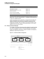
The DECnet for OpenVMS Configuration Database . . . . . . . . . . . . . . . . . .
The Volatile Database . . . . . . . . . . . . . . . . . . . . . . . . . . . . . . . . . . . . .
The Permanent Database . . . . . . . . . . . . . . . . . . . . . . . . . . . . . . . . . . .
The Network Control Program . . . . . . . . . . . . . . . . . . . . . . . . . . . . . . . . . .
Node Commands . . . . . . . . . . . . . . . . . . . . . . . . . . . . . . . . . . . . . . . . . . . .
Executor Node Commands . . . . . . . . . . . . . . . . . . . . . . . . . . . . . . . . . .
SET EXECUTOR NODE Command . . . . . . . . . . . . . . . . . . . . . . . .
TELL Prefix . . . . . . . . . . . . . . . . . . . . . . . . . . . . . . . . . . . . . . . . . .
Node Identification . . . . . . . . . . . . . . . . . . . . . . . . . . . . . . . . . . . . . . . .
Local Node Identification Parameter . . . . . . . . . . . . . . . . . . . . . . .
Using and Removing Node Names and Addresses . . . . . . . . . . . . .
Identifying VMScluster Nodes . . . . . . . . . . . . . . . . . . . . . . . . . . . . . . .
Setting an Alias Node Identifier for the Executor . . . . . . . . . . . . .
Enabling Aliases for Nodes in a VMScluster . . . . . . . . . . . . . . . . .
Node Parameters . . . . . . . . . . . . . . . . . . . . . . . . . . . . . . . . . . . . . . . . .
Logical Link Control . . . . . . . . . . . . . . . . . . . . . . . . . . . . . . . . . . .
Operational State of the Local Node . . . . . . . . . . . . . . . . . . . . . . .
Copying Node Databases . . . . . . . . . . . . . . . . . . . . . . . . . . . . . . . . . . .
COPY Command Parameters and Qualifiers . . . . . . . . . . . . . . . . .
Clearing and Purging the Local Node Database . . . . . . . . . . . . . . .
Copying the Node Database from a Remote Node . . . . . . . . . . . . .
Example of Copying Remote Node Data . . . . . . . . . . . . . . . . . . . . .
Copying the Permanent Node Database Using DCL COPY . . . . . .
Node Counters . . . . . . . . . . . . . . . . . . . . . . . . . . . . . . . . . . . . . . . . . . .
Using the DECdns Namespace . . . . . . . . . . . . . . . . . . . . . . . . . . . . . . . . .
Requirements . . . . . . . . . . . . . . . . . . . . . . . . . . . . . . . . . . . . . . . . . . .
How DECnet for OpenVMS Nodes Use DECdns . . . . . . . . . . . . . . . . .
Enabling and Disabling the DECdns Namespace Interface . . . . . . . . .
Circuit Commands . . . . . . . . . . . . . . . . . . . . . . . . . . . . . . . . . . . . . . . . . . .
Circuit Identification . . . . . . . . . . . . . . . . . . . . . . . . . . . . . . . . . . . . . .
DDCMP Circuit Identification . . . . . . . . . . . . . . . . . . . . . . . . . . . .
CI Circuit Identification . . . . . . . . . . . . . . . . . . . . . . . . . . . . . . . . .
Ethernet and FDDI Circuit Identification . . . . . . . . . . . . . . . . . . .
Circuit Parameters . . . . . . . . . . . . . . . . . . . . . . . . . . . . . . . . . . . . . . . .
Operational State of the Circuit . . . . . . . . . . . . . . . . . . . . . . . . . . .
Circuit Timers . . . . . . . . . . . . . . . . . . . . . . . . . . . . . . . . . . . . . . . .
3–1
3–2
3–2
3–2
3–5
3–5
3–6
3–6
3–7
3–8
3–9
3–9
3–10
3–10
3–11
3–14
3–16
3–17
3–18
3–18
3–19
3–20
3–21
3–21
3–22
3–22
3–22
3–23
3–24
3–24
3–24
3–26
3–26
3–26
3–28
3–29
.
.
.
.
.
.
.
.
.
.
.
.
.
.
.
.
.
.
.
.
.
.
.
.
.
.
.
.
.
.
Part II Network System Management
3 Managing and Monitoring the Network
3.1
3.1.1
3.1.2
3.2
3.3
3.3.1
3.3.1.1
3.3.1.2
3.3.2
3.3.2.1
3.3.2.2
3.3.3
3.3.3.1
3.3.3.2
3.3.4
3.3.4.1
3.3.4.2
3.3.5
3.3.5.1
3.3.5.2
3.3.5.3
3.3.5.4
3.3.5.5
3.3.6
3.4
3.4.1
3.4.2
3.4.3
3.5
3.5.1
3.5.1.1
3.5.1.2
3.5.1.3
3.5.2
3.5.2.1
3.5.2.2
v
3.5.3
3.5.3.1
3.5.3.2
3.5.4
3.5.5
3.5.5.1
3.5.5.2
3.5.5.3
3.5.6
3.6
3.6.1
3.6.1.1
3.6.2
3.6.2.1
3.6.2.2
3.6.3
3.6.3.1
3.6.3.2
3.6.3.3
3.6.3.4
3.6.3.5
3.6.4
3.6.5
3.6.5.1
3.6.5.2
3.6.6
3.7
3.7.1
3.7.2
3.7.3
3.7.3.1
3.7.3.2
3.7.4
3.7.4.1
3.7.4.2
3.7.4.3
3.7.4.4
3.7.4.5
3.7.5
3.7.6
3.8
3.8.1
3.8.2
3.8.3
3.8.3.1
3.8.3.2
3.8.3.3
3.8.3.4
3.9
3.9.1
3.9.1.1
3.9.1.2
3.9.1.3
3.9.1.4
vi
DDCMP Circuit Parameters . . . . . . . . . . . . . . . . . . . . . . . . . .
DDCMP Circuit Level Verification . . . . . . . . . . . . . . . . . . .
DDCMP Tributary Control . . . . . . . . . . . . . . . . . . . . . . . . .
Ethernet and FDDI Circuit Parameters . . . . . . . . . . . . . . . . . .
Ethernet Configurator Module Commands . . . . . . . . . . . . . . . .
Enabling Surveillance by the Ethernet Configurator . . . . .
Obtaining a List of Systems on Ethernet Circuits . . . . . . .
Disabling Surveillance by the Ethernet Configurator . . . . .
Circuit Counters . . . . . . . . . . . . . . . . . . . . . . . . . . . . . . . . . . .
Line Commands . . . . . . . . . . . . . . . . . . . . . . . . . . . . . . . . . . . . . . .
Line Identification . . . . . . . . . . . . . . . . . . . . . . . . . . . . . . . . . .
Line Protocols . . . . . . . . . . . . . . . . . . . . . . . . . . . . . . . . . .
Line Parameters . . . . . . . . . . . . . . . . . . . . . . . . . . . . . . . . . . .
Operational State of Lines . . . . . . . . . . . . . . . . . . . . . . . . .
Buffer Size . . . . . . . . . . . . . . . . . . . . . . . . . . . . . . . . . . . . .
DDCMP Line Parameters . . . . . . . . . . . . . . . . . . . . . . . . . . . .
Line Buffers . . . . . . . . . . . . . . . . . . . . . . . . . . . . . . . . . . . .
Duplex Mode . . . . . . . . . . . . . . . . . . . . . . . . . . . . . . . . . . .
Line Timers . . . . . . . . . . . . . . . . . . . . . . . . . . . . . . . . . . . .
Satellite Transmission Control . . . . . . . . . . . . . . . . . . . . . .
Asynchronous DDCMP Line Parameters . . . . . . . . . . . . . .
Ethernet Line Parameters . . . . . . . . . . . . . . . . . . . . . . . . . . . .
FDDI Line Parameters . . . . . . . . . . . . . . . . . . . . . . . . . . . . . . .
Displaying the Hardware Address . . . . . . . . . . . . . . . . . . .
Displaying the Line Status . . . . . . . . . . . . . . . . . . . . . . . .
Line Counters . . . . . . . . . . . . . . . . . . . . . . . . . . . . . . . . . . . . .
Routing Commands . . . . . . . . . . . . . . . . . . . . . . . . . . . . . . . . . . . .
Specifying the Node Type . . . . . . . . . . . . . . . . . . . . . . . . . . . . .
Specifying the Area Number in a Node Address . . . . . . . . . . .
Setting Routing Configuration Limits . . . . . . . . . . . . . . . . . . .
Maximum Number of Routers and End Nodes Allowed . . .
Maximum Number of Areas Allowed . . . . . . . . . . . . . . . . .
Routing Control Parameters . . . . . . . . . . . . . . . . . . . . . . . . . .
Circuit Cost Control Parameter . . . . . . . . . . . . . . . . . . . . .
Maximum Path Control Parameters . . . . . . . . . . . . . . . . .
Route-Through Control Parameter . . . . . . . . . . . . . . . . . . .
Equal Cost Path Parameters . . . . . . . . . . . . . . . . . . . . . . .
Area Path Control Parameters . . . . . . . . . . . . . . . . . . . . . .
Routing Message Timers . . . . . . . . . . . . . . . . . . . . . . . . . . . . .
CI End Node Circuit Failover . . . . . . . . . . . . . . . . . . . . . . . . .
Logical Link Commands . . . . . . . . . . . . . . . . . . . . . . . . . . . . . . . . .
Maximum Number of Links . . . . . . . . . . . . . . . . . . . . . . . . . . .
Disconnecting Logical Links . . . . . . . . . . . . . . . . . . . . . . . . . . .
Logical Link Protocol Parameters . . . . . . . . . . . . . . . . . . . . . .
Incoming and Outgoing Timers . . . . . . . . . . . . . . . . . . . . .
Inactivity Timer . . . . . . . . . . . . . . . . . . . . . . . . . . . . . . . . .
NSP Message Retransmission . . . . . . . . . . . . . . . . . . . . . .
Pipeline Quota . . . . . . . . . . . . . . . . . . . . . . . . . . . . . . . . . .
Object Commands . . . . . . . . . . . . . . . . . . . . . . . . . . . . . . . . . . . . .
DECnet for OpenVMS Objects . . . . . . . . . . . . . . . . . . . . . . . . .
DECnet for OpenVMS Object Identification . . . . . . . . . . . .
Using the Cluster Alias Node Identifier for the Object . . .
Example of Using the Cluster Alias Node Identifier . . . . .
DECnet for OpenVMS Command Procedure Identification
.
.
.
.
.
.
.
.
.
.
.
.
.
.
.
.
.
.
.
.
.
.
.
.
.
.
.
.
.
.
.
.
.
.
.
.
.
.
.
.
.
.
.
.
.
.
.
.
.
.
.
.
.
.
.
.
.
.
.
.
.
.
.
.
.
.
.
.
.
.
.
.
.
.
.
.
.
.
.
.
.
.
.
.
.
.
.
.
.
.
.
.
.
.
.
.
.
.
.
.
.
.
.
.
.
.
.
.
.
.
.
.
.
.
.
.
.
.
.
.
.
.
.
.
.
.
.
.
.
.
.
.
.
.
.
.
.
.
.
.
.
.
.
.
.
.
.
.
.
.
.
.
.
.
.
.
.
.
.
.
.
.
.
.
.
.
.
.
.
.
.
.
.
.
.
.
.
.
.
.
.
.
.
.
.
.
.
.
.
.
.
.
.
.
.
.
.
.
.
.
.
.
.
.
.
.
.
.
.
.
.
.
.
.
.
.
.
.
.
.
.
.
.
.
.
.
.
.
.
.
.
.
.
.
.
.
.
.
.
.
.
.
.
.
.
.
.
.
.
.
.
.
.
.
.
.
.
.
.
.
.
.
.
.
.
.
.
.
.
.
.
.
.
.
.
.
.
.
.
.
.
.
.
.
.
.
.
.
.
.
.
.
.
.
.
.
.
.
.
.
.
.
.
.
.
.
.
.
.
.
.
.
.
.
.
.
.
.
.
.
.
.
.
.
3–30
3–30
3–31
3–33
3–34
3–34
3–34
3–35
3–35
3–36
3–36
3–37
3–38
3–41
3–41
3–42
3–42
3–43
3–43
3–44
3–45
3–46
3–46
3–46
3–47
3–48
3–49
3–49
3–50
3–50
3–50
3–51
3–51
3–51
3–52
3–53
3–53
3–54
3–54
3–55
3–56
3–56
3–56
3–56
3–57
3–57
3–57
3–58
3–59
3–59
3–59
3–60
3–60
3–61
3.10
Logging Commands . . . . . . . . . . . . . . . . . . . . . . . . . . . . . . . . . . . . . . . . . .
3.10.1
Event Identification . . . . . . . . . . . . . . . . . . . . . . . . . . . . . . . . . . . . . . .
3.10.2
Identifying the Source for Events . . . . . . . . . . . . . . . . . . . . . . . . . . . . .
3.10.3
Identifying the Location for Logging Events . . . . . . . . . . . . . . . . . . . .
3.10.4
Controlling the Operational State of Logging . . . . . . . . . . . . . . . . . . . .
3.10.5
Event Logging Example . . . . . . . . . . . . . . . . . . . . . . . . . . . . . . . . . . . .
3.10.6
Using a Logging Monitor Program . . . . . . . . . . . . . . . . . . . . . . . . . . . .
3.11
Network Access Control Commands . . . . . . . . . . . . . . . . . . . . . . . . . . . . . .
3.11.1
Specifying Passwords for Routing Initialization . . . . . . . . . . . . . . . . . .
3.11.2
System-Level Access Control Commands . . . . . . . . . . . . . . . . . . . . . . .
3.11.2.1
Establishing Default Privileged and Nonprivileged Accounts . . . . .
3.11.2.2
Specifying Privileges for Objects . . . . . . . . . . . . . . . . . . . . . . . . . .
3.11.2.3
Specifying Privileges Required for Outgoing Connections to
Objects . . . . . . . . . . . . . . . . . . . . . . . . . . . . . . . . . . . . . . . . . . . . . .
3.11.2.4
Setting Default Inbound Access Control Information . . . . . . . . . . .
3.11.2.5
Indicating Access Controls for Remote Command Execution . . . . .
3.11.3
Node-Level Access Control Commands . . . . . . . . . . . . . . . . . . . . . . . . .
3.11.4
Proxy Login Access Control Commands . . . . . . . . . . . . . . . . . . . . . . . .
3.12
Monitoring the Network . . . . . . . . . . . . . . . . . . . . . . . . . . . . . . . . . . . . . . .
3–62
3–63
3–64
3–65
3–65
3–65
3–66
3–67
3–67
3–68
3–68
3–68
3–69
3–69
3–69
3–70
3–71
3–72
4 DECnet for OpenVMS Host Services
4.1
Loading Unattended Systems Downline . . . . . . . . . . . .
4.1.1
Downline System Load Operation . . . . . . . . . . . . .
4.1.1.1
Target-Initiated Downline Load . . . . . . . . . . . .
4.1.1.2
Operator-Initiated Downline Load . . . . . . . . . .
4.1.1.3
Load Requirements . . . . . . . . . . . . . . . . . . . . .
4.1.2
Downline Load Parameters . . . . . . . . . . . . . . . . . .
4.1.2.1
TRIGGER Command . . . . . . . . . . . . . . . . . . . .
4.1.2.2
LOAD Command . . . . . . . . . . . . . . . . . . . . . . .
4.1.2.3
Host Identification . . . . . . . . . . . . . . . . . . . . . .
4.1.2.4
Load File Identification . . . . . . . . . . . . . . . . . .
4.1.2.5
Management File Identification . . . . . . . . . . . .
4.1.2.6
Software Type . . . . . . . . . . . . . . . . . . . . . . . . .
4.1.2.7
Load Assist Agent Identification . . . . . . . . . . .
4.1.2.8
Load Assist Parameter Identification . . . . . . . .
4.1.2.9
CPU and Software Identification . . . . . . . . . . .
4.1.2.10
Service Circuit Identification . . . . . . . . . . . . . .
4.1.2.11
Service Passwords . . . . . . . . . . . . . . . . . . . . . .
4.1.2.12
Diagnostic File . . . . . . . . . . . . . . . . . . . . . . . . .
4.2
Dumping Memory Upline from an Unattended System
4.2.1
Upline Dump Procedures . . . . . . . . . . . . . . . . . . . .
4.2.2
Upline Dump Requirements . . . . . . . . . . . . . . . . . .
4.3
Loading RSX–11S Tasks Downline . . . . . . . . . . . . . . . .
4.3.1
Setting Up the Satellite System . . . . . . . . . . . . . . .
4.3.2
Host Loader Mapping Table . . . . . . . . . . . . . . . . . .
4.3.3
HLD Operation and Error Reporting . . . . . . . . . . .
4.3.3.1
HLD Error Messages . . . . . . . . . . . . . . . . . . . .
4.3.4
Checkpointing RSX–11S Tasks . . . . . . . . . . . . . . . .
4.3.5
Overlaying RSX–11S Tasks . . . . . . . . . . . . . . . . . .
4.4
Connection to Remote Console . . . . . . . . . . . . . . . . . . .
.
.
.
.
.
.
.
.
.
.
.
.
.
.
.
.
.
.
.
.
.
.
.
.
.
.
.
.
.
.
.
.
.
.
.
.
.
.
.
.
.
.
.
.
.
.
.
.
.
.
.
.
.
.
.
.
.
.
.
.
.
.
.
.
.
.
.
.
.
.
.
.
.
.
.
.
.
.
.
.
.
.
.
.
.
.
.
.
.
.
.
.
.
.
.
.
.
.
.
.
.
.
.
.
.
.
.
.
.
.
.
.
.
.
.
.
.
.
.
.
.
.
.
.
.
.
.
.
.
.
.
.
.
.
.
.
.
.
.
.
.
.
.
.
.
.
.
.
.
.
.
.
.
.
.
.
.
.
.
.
.
.
.
.
.
.
.
.
.
.
.
.
.
.
.
.
.
.
.
.
.
.
.
.
.
.
.
.
.
.
.
.
.
.
.
.
.
.
.
.
.
.
.
.
.
.
.
.
.
.
.
.
.
.
.
.
.
.
.
.
.
.
.
.
.
.
.
.
.
.
.
.
.
.
.
.
.
.
.
.
.
.
.
.
.
.
.
.
.
.
.
.
.
.
.
.
.
.
.
.
.
.
.
.
.
.
.
.
.
.
.
.
.
.
.
.
.
.
.
.
.
.
.
.
.
.
.
.
.
.
.
.
.
.
.
.
.
.
.
.
.
.
.
.
.
.
.
.
.
.
.
.
.
.
.
.
.
.
.
.
.
.
.
.
.
.
.
.
.
.
.
.
.
.
.
.
.
.
.
.
.
.
.
.
.
.
.
.
.
.
.
.
.
.
.
.
.
.
.
.
.
.
.
.
.
.
.
.
.
.
.
.
.
.
.
.
.
.
.
.
.
.
.
.
.
.
.
.
.
.
.
.
.
.
.
.
.
.
.
.
.
.
.
.
.
.
.
.
.
.
.
.
.
.
.
.
.
.
.
.
.
.
.
.
.
.
.
.
.
.
.
.
.
.
.
4–1
4–2
4–2
4–4
4–4
4–5
4–5
4–6
4–9
4–9
4–9
4–10
4–10
4–10
4–10
4–10
4–11
4–11
4–11
4–11
4–13
4–14
4–15
4–16
4–17
4–17
4–18
4–18
4–18
vii
Part III Configuring, Installing, and Testing Networks
5 Configuring a Network
5.1
Prerequisites for Establishing a Network . . . . . . . . . . . . . . . . . . . . . . .
5.1.1
Required Privileges . . . . . . . . . . . . . . . . . . . . . . . . . . . . . . . . . . . . .
5.2
Configuration Procedures . . . . . . . . . . . . . . . . . . . . . . . . . . . . . . . . . . . .
5.2.1
Default Access Options . . . . . . . . . . . . . . . . . . . . . . . . . . . . . . . . . .
5.2.1.1
Specific Default Accounts . . . . . . . . . . . . . . . . . . . . . . . . . . . . . .
5.2.2
Using NETCONFIG.COM . . . . . . . . . . . . . . . . . . . . . . . . . . . . . . . .
5.2.2.1
NETCONFIG.COM Example . . . . . . . . . . . . . . . . . . . . . . . . . . .
5.2.2.2
NETCONFIG_UPDATE.COM for Existing Network
Configurations . . . . . . . . . . . . . . . . . . . . . . . . . . . . . . . . . . . . . .
5.2.3
Tailoring the Configuration Database . . . . . . . . . . . . . . . . . . . . . . .
5.2.3.1
Running DECnet over the CI . . . . . . . . . . . . . . . . . . . . . . . . . . .
5.2.3.2
Running DECnet over Terminal Lines . . . . . . . . . . . . . . . . . . . .
5.2.3.3
Installing Static Asynchronous Lines . . . . . . . . . . . . . . . . . . . . .
5.2.3.4
Installing Dynamic Asynchronous Lines . . . . . . . . . . . . . . . . . .
5.3
Network Configuration Examples . . . . . . . . . . . . . . . . . . . . . . . . . . . . .
5.3.1
Ethernet Network Example . . . . . . . . . . . . . . . . . . . . . . . . . . . . . . .
5.3.2
FDDI Network Example . . . . . . . . . . . . . . . . . . . . . . . . . . . . . . . . .
5.3.3
Synchronous DDCMP Point-to-Point Network Example . . . . . . . . .
5.3.4
DDCMP Multipoint Network Example . . . . . . . . . . . . . . . . . . . . . . .
5.3.5
Static Asynchronous DDCMP Network Example . . . . . . . . . . . . . . .
5.3.6
Dynamic Asynchronous DDCMP Network Examples . . . . . . . . . . . .
5.4
System Configuration Guidelines . . . . . . . . . . . . . . . . . . . . . . . . . . . . . .
5.4.1
Normal Memory Requirements . . . . . . . . . . . . . . . . . . . . . . . . . . . .
5.4.2
Critical Routing Node Requirements . . . . . . . . . . . . . . . . . . . . . . . .
5.4.3
CPU Time Requirements . . . . . . . . . . . . . . . . . . . . . . . . . . . . . . . . .
5.4.3.1
Adjusting NETACP Quotas with the NETACP$ Logical Names .
5.4.3.2
Adjusting NETACP Node Data Block Allocations with NET$
Logical Names . . . . . . . . . . . . . . . . . . . . . . . . . . . . . . . . . . . . . .
5.4.4
Permanent Database Considerations in VMSclusters . . . . . . . . . . .
.
.
.
.
.
.
.
.
.
.
.
.
.
.
5–1
5–1
5–3
5–3
5–4
5–5
5–7
.
.
.
.
.
.
.
.
.
.
.
.
.
.
.
.
.
.
.
.
.
.
.
.
.
.
.
.
.
.
.
.
.
.
.
.
5–10
5–11
5–11
5–12
5–12
5–14
5–19
5–20
5–21
5–23
5–25
5–27
5–29
5–31
5–31
5–32
5–32
5–33
..
..
5–34
5–34
6 Installing a Network
.
.
.
.
.
.
.
.
.
.
.
.
.
.
.
.
.
.
.
.
.
.
.
.
.
.
.
.
.
.
.
.
6–1
6–2
6–2
6–3
7.1
Node-Level Tests . . . . . . . . . . . . . . . . . . . . . . . . . . . . . . . . . . . . .
7.1.1
Remote Loopback Test . . . . . . . . . . . . . . . . . . . . . . . . . . . . . .
7.1.2
Local and Remote Loopback Tests Using a Loop Node Name .
7.1.2.1
Local-to-Remote Loopback Testing . . . . . . . . . . . . . . . . . .
7.1.2.2
Local-to-Local Controller Loopback Testing . . . . . . . . . . .
7.1.3
Local Loopback Test . . . . . . . . . . . . . . . . . . . . . . . . . . . . . . . .
7.2
Circuit-Level Tests . . . . . . . . . . . . . . . . . . . . . . . . . . . . . . . . . . . .
7.2.1
Software Loopback Test . . . . . . . . . . . . . . . . . . . . . . . . . . . . .
7.2.2
Controller Loopback Test . . . . . . . . . . . . . . . . . . . . . . . . . . . .
.
.
.
.
.
.
.
.
.
.
.
.
.
.
.
.
.
.
.
.
.
.
.
.
.
.
.
.
.
.
.
.
.
.
.
.
.
.
.
.
.
.
.
.
.
.
.
.
.
.
.
.
.
.
.
.
.
.
.
.
.
.
.
7–1
7–2
7–3
7–4
7–5
7–6
7–6
7–7
7–8
6.1
6.2
6.3
6.4
Installing a DECnet for OpenVMS Key . . . . . . . . . . . . . . .
Bringing Up Your Network Node Using STARTNET.COM .
Testing the Installation with UETP Test Procedure . . . . . .
Shutting Down Your DECnet for OpenVMS Node . . . . . . .
.
.
.
.
.
.
.
.
.
.
.
.
.
.
.
.
7 Testing the Network
viii
Circuit-Level Loopback Testing . . . . . . . . . . . . . . . . . . .
Testing with the PHYSICAL ADDRESS and NODE
Parameters . . . . . . . . . . . . . . . . . . . . . . . . . . . . . . .
7.2.3.2
Loopback Assistance . . . . . . . . . . . . . . . . . . . . . . . .
7.3
Using the MIRROR$SIZE Logical . . . . . . . . . . . . . . . . . . . .
7.2.3
7.2.3.1
...........
7–9
...........
...........
...........
7–9
7–11
7–12
Part IV Network User Operations
8 Performing Network User Operations
8.1
8.2
8.3
8.3.1
8.3.2
8.3.3
8.4
8.4.1
8.4.1.1
8.4.1.2
8.4.2
8.4.3
8.4.3.1
8.4.3.2
8.4.3.3
8.4.3.4
8.5
8.5.1
8.5.2
8.5.3
8.5.4
8.5.4.1
8.5.4.2
8.5.4.3
8.5.4.4
8.5.4.5
8.5.5
8.5.5.1
8.5.5.2
8.5.5.3
8.5.5.4
8.6
8.6.1
8.6.1.1
8.6.1.2
8.6.1.3
8.6.1.4
8.6.1.5
8.6.1.6
8.6.1.7
Retrieving Network Status Information . . . . . . . . . . . . . . . . . . . . . .
Establishing Communication with a Remote Node . . . . . . . . . . . . .
Accessing Files on Remote Nodes . . . . . . . . . . . . . . . . . . . . . . . . . . .
Using DCL Commands and Command Procedures . . . . . . . . . .
Using Higher-Level Language Programs . . . . . . . . . . . . . . . . . .
Using OpenVMS RMS Services from Programs . . . . . . . . . . . . .
Performing Task-to-Task Operations . . . . . . . . . . . . . . . . . . . . . . . .
Transparent and Nontransparent Task-to-Task Communication
Transparent Communication . . . . . . . . . . . . . . . . . . . . . . . .
Nontransparent Communication . . . . . . . . . . . . . . . . . . . . .
Task Specification Strings in Task-to-Task Applications . . . . . .
Functions Required for Performing Task-to-Task Operations . . .
Initiating a Logical Link Connection . . . . . . . . . . . . . . . . . .
Completing the Logical Link Connection . . . . . . . . . . . . . . .
Exchanging Messages . . . . . . . . . . . . . . . . . . . . . . . . . . . . .
Terminating a Logical Link Connection . . . . . . . . . . . . . . . .
Performing Transparent Task-to-Task Operations . . . . . . . . . . . . . .
Using DCL Commands and Command Procedures . . . . . . . . . .
Using Programming Language I/O Statements . . . . . . . . . . . . .
Using OpenVMS RMS Service Calls in Programs . . . . . . . . . . .
Using System Service Calls in Programs . . . . . . . . . . . . . . . . . .
Requesting a Logical Link . . . . . . . . . . . . . . . . . . . . . . . . . .
Completing the Logical Link Connection . . . . . . . . . . . . . . .
Exchanging Messages . . . . . . . . . . . . . . . . . . . . . . . . . . . . .
Terminating the Logical Link . . . . . . . . . . . . . . . . . . . . . . . .
Status and Error Reporting . . . . . . . . . . . . . . . . . . . . . . . . .
Summary of System Service Calls for Transparent Operations .
$ASSIGN . . . . . . . . . . . . . . . . . . . . . . . . . . . . . . . . . . . . . . .
$QIO (Sending a Message to a Target Task) . . . . . . . . . . . .
$QIO (Receiving a Message from a Target Task) . . . . . . . . .
$DASSGN (Disconnecting a Logical Link) . . . . . . . . . . . . . .
Performing Nontransparent Task-to-Task Operations . . . . . . . . . . .
Using System Services for Nontransparent Operations . . . . . . .
Assigning a Channel to _NET: and Creating a Mailbox . . . .
Mailbox Message Format . . . . . . . . . . . . . . . . . . . . . . . . . . .
Requesting a Logical Link Connection . . . . . . . . . . . . . . . . .
Using the Network Connect Block . . . . . . . . . . . . . . . . . . . .
Completing the Establishment of a Logical Link . . . . . . . . .
Disconnecting or Aborting the Logical Link . . . . . . . . . . . . .
Terminating the Logical Link . . . . . . . . . . . . . . . . . . . . . . . .
.
.
.
.
.
.
.
.
.
.
.
.
.
.
.
.
.
.
.
.
.
.
.
.
.
.
.
.
.
.
.
.
.
.
.
.
.
.
.
.
.
.
.
.
.
.
.
.
.
.
.
.
.
.
.
.
.
.
.
.
.
.
.
.
.
.
.
.
.
.
.
.
.
.
.
.
.
.
.
.
.
.
.
.
.
.
.
.
.
.
.
.
.
.
.
.
.
.
.
.
.
.
.
.
.
.
.
.
.
.
.
.
.
.
.
.
.
.
.
.
.
.
.
.
.
.
.
.
.
.
.
.
.
.
.
.
.
.
.
.
.
.
.
.
.
.
.
.
.
.
.
.
.
.
.
.
.
.
.
.
.
.
.
.
.
.
.
.
.
.
.
.
.
.
.
.
.
.
.
.
.
.
.
.
.
.
.
.
.
.
.
.
.
.
.
.
.
.
.
.
8–1
8–2
8–3
8–4
8–4
8–5
8–7
8–7
8–7
8–8
8–9
8–10
8–11
8–11
8–13
8–14
8–15
8–15
8–16
8–16
8–17
8–18
8–18
8–19
8–19
8–19
8–20
8–20
8–21
8–22
8–23
8–24
8–24
8–25
8–26
8–27
8–27
8–28
8–30
8–31
ix
8.6.2
System Service Calls for Nontransparent Operations . . . . .
8.6.2.1
$ASSIGN (I/O Channel Assignment) . . . . . . . . . . . . . . .
8.6.2.2
$QIO (Requesting a Logical Link Connection) . . . . . . . .
8.6.2.3
$QIO (Accepting Logical Link Connection Request) . . . .
8.6.2.4
$QIO (Rejecting a Logical Link Connection Request) . . .
8.6.2.5
$QIO (Sending a Message to a Target Task) . . . . . . . . .
8.6.2.6
$QIO (Receiving a Message from a Target Task) . . . . . .
8.6.2.7
$QIO (Sending an Interrupt Message to a Target Task)
8.6.2.8
$QIO (Synchronously Disconnecting a Logical Link) . . .
8.6.2.9
$QIO (Aborting a Logical Link) . . . . . . . . . . . . . . . . . . .
8.6.2.10
$QIO (Declaring a Network Name or Object Number) . .
8.6.2.11
$DASSGN (Terminating a Logical Link) . . . . . . . . . . . .
8.7
Designing Tasks . . . . . . . . . . . . . . . . . . . . . . . . . . . . . . . . . . . . .
8.7.1
DCL Command Procedure for Task-to-Task Communication
8.7.2
FORTRAN Program for Task-to-Task Communication . . . . .
8.7.3
Programs for Nontransparent Task-to-Task Communication
.
.
.
.
.
.
.
.
.
.
.
.
.
.
.
.
.
.
.
.
.
.
.
.
.
.
.
.
.
.
.
.
.
.
.
.
.
.
.
.
.
.
.
.
.
.
.
.
.
.
.
.
.
.
.
.
.
.
.
.
.
.
.
.
.
.
.
.
.
.
.
.
.
.
.
.
.
.
.
.
.
.
.
.
.
.
.
.
.
.
.
.
.
.
.
.
.
.
.
.
.
.
.
.
.
.
.
.
.
.
.
.
.
.
.
.
.
.
.
.
.
.
.
.
.
.
.
.
8–31
8–32
8–32
8–33
8–34
8–35
8–35
8–35
8–36
8–37
8–38
8–39
8–39
8–39
8–40
8–43
.
.
.
.
.
.
.
.
.
.
.
.
.
.
.
.
.
.
.
.
.
.
.
.
.
.
.
.
.
.
.
.
.
.
.
.
.
.
.
.
.
.
.
.
.
.
.
.
.
.
.
.
.
.
.
.
.
.
.
.
.
.
.
.
.
.
.
.
.
.
.
.
.
.
.
.
.
.
.
.
.
.
.
.
.
.
.
.
.
.
.
.
.
.
.
.
.
.
.
.
.
.
.
.
.
.
.
.
.
.
.
.
.
.
.
.
.
.
.
.
.
.
.
.
.
.
.
.
.
.
.
.
.
.
.
.
.
.
.
.
.
.
.
.
.
.
.
.
.
.
.
.
.
.
.
.
.
.
.
.
.
.
.
.
.
.
.
.
.
.
.
.
.
.
.
.
.
.
.
.
.
.
.
.
.
.
.
.
.
.
.
.
.
.
.
.
.
.
.
.
.
.
.
.
.
.
.
.
.
.
.
.
.
.
.
.
.
.
.
.
.
.
.
.
.
.
.
.
.
.
.
.
.
.
.
.
.
.
.
.
.
.
.
.
.
.
.
.
.
.
.
.
.
.
.
.
.
.
.
.
.
.
.
.
.
.
.
.
.
.
.
.
.
.
.
.
.
.
.
.
9–1
9–2
9–2
9–3
9–3
9–4
9–4
9–4
9–5
9–5
9–5
9–6
9–6
9–6
9–6
9–7
9–7
9–7
9–7
9–8
9–8
9–8
9–9
9–9
9–9
9–9
9–10
9–10
9–11
9–11
9–11
9–11
9–12
9–12
9–13
9 File Operations in a Multivendor Network Environment
9.1
9.2
9.2.1
9.2.2
9.2.3
9.2.4
9.2.4.1
9.2.4.2
9.3
9.3.1
9.3.2
9.3.3
9.3.4
9.3.4.1
9.3.4.2
9.3.4.3
9.3.4.4
9.3.4.5
9.4
9.4.1
9.4.2
9.4.3
9.4.4
9.4.4.1
9.5
9.5.1
9.5.2
9.5.3
9.5.4
9.5.4.1
9.5.4.2
9.6
9.6.1
9.6.1.1
9.6.1.2
x
DECnet for OpenVMS Restrictions . . . . . . . . . . . . . . . . . . . . .
OpenVMS to IAS Network Operation . . . . . . . . . . . . . . . . . . .
File Formats and Access Modes . . . . . . . . . . . . . . . . . . . . .
OpenVMS RMS Interface . . . . . . . . . . . . . . . . . . . . . . . . . .
File Specifications . . . . . . . . . . . . . . . . . . . . . . . . . . . . . . .
DCL Considerations . . . . . . . . . . . . . . . . . . . . . . . . . . . . . .
APPEND . . . . . . . . . . . . . . . . . . . . . . . . . . . . . . . . . . .
COPY . . . . . . . . . . . . . . . . . . . . . . . . . . . . . . . . . . . . . .
OpenVMS to RSTS/E Network Operation . . . . . . . . . . . . . . . .
File Formats and Access Modes . . . . . . . . . . . . . . . . . . . . .
OpenVMS RMS Interface . . . . . . . . . . . . . . . . . . . . . . . . . .
File Specifications . . . . . . . . . . . . . . . . . . . . . . . . . . . . . . .
DCL Considerations . . . . . . . . . . . . . . . . . . . . . . . . . . . . . .
APPEND . . . . . . . . . . . . . . . . . . . . . . . . . . . . . . . . . . .
COPY . . . . . . . . . . . . . . . . . . . . . . . . . . . . . . . . . . . . . .
DELETE . . . . . . . . . . . . . . . . . . . . . . . . . . . . . . . . . . .
DIRECTORY . . . . . . . . . . . . . . . . . . . . . . . . . . . . . . . .
DUMP/RECORDS and TYPE Commands . . . . . . . . . .
OpenVMS to RSX Network Operation Using RMS-based FAL .
File Formats and Access Modes . . . . . . . . . . . . . . . . . . . . .
OpenVMS RMS Interface . . . . . . . . . . . . . . . . . . . . . . . . . .
File Specifications . . . . . . . . . . . . . . . . . . . . . . . . . . . . . . .
DCL Considerations . . . . . . . . . . . . . . . . . . . . . . . . . . . . . .
COPY . . . . . . . . . . . . . . . . . . . . . . . . . . . . . . . . . . . . . .
OpenVMS to RSX Network Operation Using FCS-based FAL .
File Formats and Access Modes . . . . . . . . . . . . . . . . . . . . .
OpenVMS RMS Interface . . . . . . . . . . . . . . . . . . . . . . . . . .
File Specifications . . . . . . . . . . . . . . . . . . . . . . . . . . . . . . .
DCL Considerations . . . . . . . . . . . . . . . . . . . . . . . . . . . . . .
APPEND . . . . . . . . . . . . . . . . . . . . . . . . . . . . . . . . . . .
COPY . . . . . . . . . . . . . . . . . . . . . . . . . . . . . . . . . . . . . .
OpenVMS to RT–11 Network Operations . . . . . . . . . . . . . . . . .
File System Constraints . . . . . . . . . . . . . . . . . . . . . . . . . . .
File Formats and Access Modes . . . . . . . . . . . . . . . . . .
OpenVMS RMS Interface . . . . . . . . . . . . . . . . . . . . . . .
.
.
.
.
.
.
.
.
.
.
.
.
.
.
.
.
.
.
.
.
.
.
.
.
.
.
.
.
.
.
.
.
.
.
.
9.6.2
File Specifications . . . . . . . . . . . . . . . . . . . . . . . . . . . . . . . . . . . . . . . .
9.6.3
DCL Considerations . . . . . . . . . . . . . . . . . . . . . . . . . . . . . . . . . . . . . . .
9.6.3.1
COPY . . . . . . . . . . . . . . . . . . . . . . . . . . . . . . . . . . . . . . . . . . . . . . .
9.6.3.2
DELETE . . . . . . . . . . . . . . . . . . . . . . . . . . . . . . . . . . . . . . . . . . . .
9.7
OpenVMS to TOPS–10 Network Operations . . . . . . . . . . . . . . . . . . . . . . .
9.7.1
File System Constraints . . . . . . . . . . . . . . . . . . . . . . . . . . . . . . . . . . . .
9.7.1.1
File Formats and Access Modes . . . . . . . . . . . . . . . . . . . . . . . . . . .
9.7.1.2
OpenVMS RMS Interface . . . . . . . . . . . . . . . . . . . . . . . . . . . . . . . .
9.7.1.3
File Specifications . . . . . . . . . . . . . . . . . . . . . . . . . . . . . . . . . . . . .
9.7.2
DCL Considerations . . . . . . . . . . . . . . . . . . . . . . . . . . . . . . . . . . . . . . .
9.7.2.1
COPY . . . . . . . . . . . . . . . . . . . . . . . . . . . . . . . . . . . . . . . . . . . . . . .
9.7.2.2
DIRECTORY . . . . . . . . . . . . . . . . . . . . . . . . . . . . . . . . . . . . . . . . .
9.8
OpenVMS to TOPS–20 Network Operations . . . . . . . . . . . . . . . . . . . . . . .
9.8.1
File System Constraints . . . . . . . . . . . . . . . . . . . . . . . . . . . . . . . . . . . .
9.8.1.1
File Formats and Access Modes . . . . . . . . . . . . . . . . . . . . . . . . . . .
9.8.1.2
OpenVMS RMS Interface . . . . . . . . . . . . . . . . . . . . . . . . . . . . . . . .
9.8.1.3
File Specifications . . . . . . . . . . . . . . . . . . . . . . . . . . . . . . . . . . . . .
9.8.2
DCL Considerations . . . . . . . . . . . . . . . . . . . . . . . . . . . . . . . . . . . . . . .
9.8.2.1
COPY . . . . . . . . . . . . . . . . . . . . . . . . . . . . . . . . . . . . . . . . . . . . . . .
9.8.2.2
DIRECTORY . . . . . . . . . . . . . . . . . . . . . . . . . . . . . . . . . . . . . . . . .
9.9
OpenVMS to MS–DOS Network Operations . . . . . . . . . . . . . . . . . . . . . . .
9.9.1
File System Constraints . . . . . . . . . . . . . . . . . . . . . . . . . . . . . . . . . . . .
9.9.1.1
File Formats and Access Modes . . . . . . . . . . . . . . . . . . . . . . . . . . .
9.9.1.2
OpenVMS RMS Interface . . . . . . . . . . . . . . . . . . . . . . . . . . . . . . . .
9.9.1.3
File Specifications . . . . . . . . . . . . . . . . . . . . . . . . . . . . . . . . . . . . .
9.9.2
DCL Considerations . . . . . . . . . . . . . . . . . . . . . . . . . . . . . . . . . . . . . . .
9.9.2.1
COPY . . . . . . . . . . . . . . . . . . . . . . . . . . . . . . . . . . . . . . . . . . . . . . .
9.9.2.2
DIRECTORY . . . . . . . . . . . . . . . . . . . . . . . . . . . . . . . . . . . . . . . . .
9.10
OpenVMS to ULTRIX Network Operations . . . . . . . . . . . . . . . . . . . . . . . .
9.10.1
File System Constraints . . . . . . . . . . . . . . . . . . . . . . . . . . . . . . . . . . . .
9.10.1.1
File Formats and Access Modes . . . . . . . . . . . . . . . . . . . . . . . . . . .
9.10.1.2
OpenVMS RMS Interface . . . . . . . . . . . . . . . . . . . . . . . . . . . . . . . .
9.10.1.3
File Specifications . . . . . . . . . . . . . . . . . . . . . . . . . . . . . . . . . . . . .
9.10.2
DCL Considerations . . . . . . . . . . . . . . . . . . . . . . . . . . . . . . . . . . . . . . .
9.10.2.1
COPY . . . . . . . . . . . . . . . . . . . . . . . . . . . . . . . . . . . . . . . . . . . . . . .
9.10.2.2
DIRECTORY . . . . . . . . . . . . . . . . . . . . . . . . . . . . . . . . . . . . . . . . .
9.11
OpenVMS to IBM Network Operations . . . . . . . . . . . . . . . . . . . . . . . . . . .
9.11.1
File System Constraints . . . . . . . . . . . . . . . . . . . . . . . . . . . . . . . . . . . .
9.11.1.1
File Formats and Access Modes . . . . . . . . . . . . . . . . . . . . . . . . . . .
9.11.1.2
OpenVMS RMS Interface . . . . . . . . . . . . . . . . . . . . . . . . . . . . . . . .
9.11.1.3
File Specifications . . . . . . . . . . . . . . . . . . . . . . . . . . . . . . . . . . . . .
9.11.2
DCL Considerations . . . . . . . . . . . . . . . . . . . . . . . . . . . . . . . . . . . . . . .
9.12
OpenVMS to VMS Network Operations . . . . . . . . . . . . . . . . . . . . . . . . . . .
9–13
9–14
9–14
9–14
9–14
9–15
9–15
9–16
9–16
9–17
9–17
9–17
9–17
9–18
9–18
9–19
9–19
9–20
9–20
9–20
9–20
9–20
9–21
9–22
9–22
9–22
9–23
9–23
9–23
9–23
9–23
9–24
9–25
9–25
9–25
9–25
9–26
9–26
9–26
9–27
9–28
9–28
9–28
Glossary
Index
xi
Examples
3–1
5–1
8–1
Using the SET OBJECT OUTGOING CONNECT PRIVILEGES
Command . . . . . . . . . . . . . . . . . . . . . . . . . . . . . . . . . . . . . . . . . . . . . . .
Sample NETCONFIG.COM Dialogue for a Routing Node . . . . . . . . . .
FORTRAN Task-to-Task Communication . . . . . . . . . . . . . . . . . . . . . . .
3–69
5–8
8–41
Figures
1–1
1–2
1–3
1–4
1–5
1–6
1–7
1–8
1–9
2–1
2–2
2–3
2–4
3–1
3–2
4–1
4–2
4–3
4–4
5–1
5–2
5–3
5–4
5–5
5–6
5–7
7–1
7–2
7–3
7–4
7–5
7–6
8–1
8–2
xii
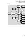
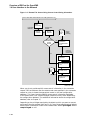
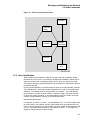
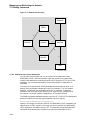
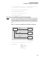
DECnet Functions and Related DNA Layers and Protocols . . . . . . . .
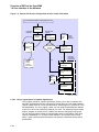
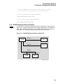
Sample DECnet for OpenVMS Phase IV Configuration . . . . . . . . . . .
DDCMP Point-to-Point and Multipoint Connections . . . . . . . . . . . . .
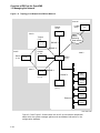
DECnet for OpenVMS Software . . . . . . . . . . . . . . . . . . . . . . . . . . . . .
Topology of a Single-Area DECnet Network . . . . . . . . . . . . . . . . . . . .
Topology of a Multiple-Area DECnet Network . . . . . . . . . . . . . . . . . .
DECnet for OpenVMS Programming Interfaces and Network Access
Types . . . . . . . . . . . . . . . . . . . . . . . . . . . . . . . . . . . . . . . . . . . . . . . . .
Remote File Access Using Access Control String Information . . . . . .
Remote File Access Using Default Access Control Information . . . . .
Multipoint Circuits and Associated Lines . . . . . . . . . . . . . . . . . . . . .
Multipoint Lines . . . . . . . . . . . . . . . . . . . . . . . . . . . . . . . . . . . . . . . .
Routing Initialization Passwords . . . . . . . . . . . . . . . . . . . . . . . . . . . .
Access Control for Inbound Connections . . . . . . . . . . . . . . . . . . . . . .
Remote Command Execution . . . . . . . . . . . . . . . . . . . . . . . . . . . . . . .
Network Circuit Costs . . . . . . . . . . . . . . . . . . . . . . . . . . . . . . . . . . . .
Operator-Initiated Downline Load over Ethernet Circuit (TRIGGER
Command) . . . . . . . . . . . . . . . . . . . . . . . . . . . . . . . . . . . . . . . . . . . . .
Operator-Initiated Downline Load over Ethernet Circuit (LOAD
Command) . . . . . . . . . . . . . . . . . . . . . . . . . . . . . . . . . . . . . . . . . . . . .
Upline Dumping of RSX–11S Memory . . . . . . . . . . . . . . . . . . . . . . . .
Downline Task Loading . . . . . . . . . . . . . . . . . . . . . . . . . . . . . . . . . . .
Dynamic Switching of Asynchronous DDCMP Lines . . . . . . . . . . . . .
An Ethernet Network Configuration . . . . . . . . . . . . . . . . . . . . . . . . .
An FDDI Network Configuration . . . . . . . . . . . . . . . . . . . . . . . . . . . .
A Synchronous DDCMP Point-to-Point Network Configuration . . . . .
A DDCMP Multipoint Network Configuration . . . . . . . . . . . . . . . . . .
A Static Asynchronous DDCMP Network Configuration . . . . . . . . . .
A Dynamic Asynchronous DDCMP Network Configuration . . . . . . . .
Remote Loopback Test . . . . . . . . . . . . . . . . . . . . . . . . . . . . . . . . . . . .
Local-to-Remote Loopback Test Using a Loop Node Name . . . . . . . . .
Local-to-Local Loopback Test Using a Loop Node Name . . . . . . . . . .
Local Loopback Test . . . . . . . . . . . . . . . . . . . . . . . . . . . . . . . . . . . . . .
Software Loopback Test . . . . . . . . . . . . . . . . . . . . . . . . . . . . . . . . . . .
Controller Loopback Testing . . . . . . . . . . . . . . . . . . . . . . . . . . . . . . . .
Mailbox Messages . . . . . . . . . . . . . . . . . . . . . . . . . . . . . . . . . . . . . . .
Mailbox Message Format . . . . . . . . . . . . . . . . . . . . . . . . . . . . . . . . . .
.
.
.
.
.
.
1–3
1–5
1–8
1–13
1–15
1–16
.
.
.
.
.
.
.
.
.
1–19
1–22
1–24
2–9
2–13
2–30
2–32
3–7
3–52
.
4–6
.
.
.
.
.
.
.
.
.
.
.
.
.
.
.
.
.
.
4–8
4–13
4–15
5–16
5–20
5–22
5–23
5–25
5–28
5–29
7–3
7–4
7–5
7–6
7–7
7–8
8–9
8–26
Tables
1–1
2–1
2–2
2–3
3–1
3–2
3–3
3–4
3–5
3–6
3–7
3–8
3–9
3–10
3–11
5–1
5–2
6–1
8–1
8–2
8–3
Programming Interfaces for Network Operations . . . . . . . .
DDCMP Circuit Devices . . . . . . . . . . . . . . . . . . . . . . . . . . .
Ethernet Circuit Devices . . . . . . . . . . . . . . . . . . . . . . . . . .
FDDI Circuit and Line Devices . . . . . . . . . . . . . . . . . . . . .
Node and Executor Parameters and Their Functions . . . . .
Types of Circuit and Applicable Circuit Parameters . . . . .
Circuit Parameters and Their Functions . . . . . . . . . . . . . .
Line Protocols . . . . . . . . . . . . . . . . . . . . . . . . . . . . . . . . . .
Line Types and Applicable Line Parameters . . . . . . . . . . .
Line Parameters and Their Functions . . . . . . . . . . . . . . . .
FDDI Line Parameters and Their Functions . . . . . . . . . . .
DDCMP Line Parameters and Their Functions (VAX only)
FDDI Line Status Parameters and Their Functions . . . . .
Object Parameters and Their Functions . . . . . . . . . . . . . . .
NCP Display Types . . . . . . . . . . . . . . . . . . . . . . . . . . . . . .
Privileges for NCP Operations . . . . . . . . . . . . . . . . . . . . . .
Permanent Configuration Database Files . . . . . . . . . . . . . .
Local Node States and Network Operations . . . . . . . . . . . .
System Service Calls for Transparent Communication . . . .
System Service Calls for Nontransparent Communication .
System Mailbox Messages . . . . . . . . . . . . . . . . . . . . . . . . .
.
.
.
.
.
.
.
.
.
.
.
.
.
.
.
.
.
.
.
.
.
.
.
.
.
.
.
.
.
.
.
.
.
.
.
.
.
.
.
.
.
.
.
.
.
.
.
.
.
.
.
.
.
.
.
.
.
.
.
.
.
.
.
.
.
.
.
.
.
.
.
.
.
.
.
.
.
.
.
.
.
.
.
.
.
.
.
.
.
.
.
.
.
.
.
.
.
.
.
.
.
.
.
.
.
.
.
.
.
.
.
.
.
.
.
.
.
.
.
.
.
.
.
.
.
.
.
.
.
.
.
.
.
.
.
.
.
.
.
.
.
.
.
.
.
.
.
.
.
.
.
.
.
.
.
.
.
.
.
.
.
.
.
.
.
.
.
.
.
.
.
.
.
.
.
.
.
.
.
.
.
.
.
.
.
.
.
.
.
1–18
2–8
2–10
2–11
3–11
3–26
3–27
3–37
3–38
3–39
3–40
3–40
3–48
3–59
3–73
5–1
5–34
6–4
8–17
8–24
8–27
xiii
Preface
Intended Audience
The DECnet for OpenVMS Networking Manual is for readers who perform
network management functions to control, monitor or test DECnet for OpenVMS.
This manual is also for users who perform remote file access or task-to-task
operations using DECnet for OpenVMS. You should be familiar with the
operating system but not necessarily experienced with DECnet operations.
Document Structure
The DECnet for OpenVMS Networking Manual is divided into four major parts:
•
Part I introduces you to basic networking concepts required to understand
DECnet for OpenVMS operation, and indicates how you can interact with the
network.
•
Part II provides usage information to those responsible for DECnet for
OpenVMS system management and explains how to use the Network Control
Program to manage the network and perform host services to remote systems
(such as downline loading and upline dumping).
•
Part III specifies the procedures for configuring, installing, and testing
DECnet for OpenVMS on a operating system.
•
Part IV describes the techniques for carrying out user operations over
the network, including accessing remote files and performing task-to-task
communications.
Associated Documents
The networking concepts and operations described in the DECnet for OpenVMS
Networking Manual are directly related to the following three manuals:
1. DECnet for OpenVMS Guide to Networking — Provides a conceptual overview
of networking concepts and DECnet for OpenVMS.
2. DECnet for OpenVMS Network Management Utilities — Provides usage
information for the Network Control Program (NCP) Utility, and information
for testing the network using DECnet Test Sender/Receiver commands,
formerly presented in a separate manual.
3. VMS DECnet Test Sender/DECnet Test Receiver Utility Manual is no longer
a separate manual. It has been incorporated into the DECnet for OpenVMS
Network Management Utilities.
See also the OpenVMS Release notes for the version you are running.
xv
The following functional specifications define Digital Network Architecture (DNA)
protocols to which all implementations of DECnet Phase IV adhere:
DECnet Digital Network Architecture General Description
Digital Data Communications Message Protocol Functional Specification
Network Services Protocol Functional Specification
Maintenance Operation Protocol Functional Specification
Data Access Protocol Functional Specification
Routing Layer Functional Specification
DNA Session Control Functional Specification
DNA Phase IV Network Management Functional Specification
Ethernet Node Product Architecture Specification
Ethernet Data Link Functional Specification
Ethernet Node Product Architecture Specification
Conventions
In this manual, every use of OpenVMS AXP means the OpenVMS AXP operating
system, every use of OpenVMS VAX means the OpenVMS VAX operating system,
and every use of OpenVMS means both the OpenVMS AXP operating system and
the OpenVMS VAX operating system.
The following conventions are used to identify information specific to OpenVMS
AXP or to OpenVMS VAX:
AXP
The AXP icon denotes the beginning of information
specific to OpenVMS AXP.
VAX
The VAX icon denotes the beginning of information
specific to OpenVMS VAX.
The diamond symbol denotes the end of a section of
information specific to OpenVMS AXP or to OpenVMS
VAX.
The following conventions are also used in this manual:
Ctrl/x
A sequence such as Ctrl/x indicates that you must hold down
the key labeled Ctrl while you press another key or a pointing
device button.
Return
In examples, a key name enclosed in a box indicates that
you press a key on the keyboard. (In text, a key name is not
enclosed in a box.)
.
.
.
boldface text
A vertical ellipsis indicates the omission of items from a code
example or command format; the items are omitted because
they are not important to the topic being discussed.
Boldface text represents the introduction of a new term or the
name of an argument, an attribute, or a reason.
Boldface text is also used to show user input in Bookreader
versions of the manual.
xvi
italic text
Italic text emphasizes important information, indicates
variables, and indicates complete titles of manuals. Italic
text also represents information that can vary in system
messages (for example, Internal error number), command lines
(for example, /PRODUCER=name), and command parameters
in text.
UPPERCASE TEXT
Uppercase text indicates a command, the name of a routine,
the name of a file, or the abbreviation for a system privilege.
-
A hyphen in code examples indicates that additional
arguments to the request are provided on the line that follows.
numbers
All numbers in text are assumed to be decimal, unless
otherwise noted. Nondecimal radixes—binary, octal, or
hexadecimal—are explicitly indicated.
Note
In this document, discussions that refer to VMScluster environments
apply to both VAXcluster systems that include only VAX nodes and
VMScluster systems that include at least one AXP node unless indicated
otherwise.
In this document, discussions that refer to DECdns apply to the
Distributed Name Service (DNS) V1.1.
xvii
Part I
Introduction to DECnet for OpenVMS
1
Overview of DECnet for OpenVMS
This chapter presents an overview of the DECnet for OpenVMS networking
software which enables access to the DECnet network: what the software is, how
to manage it, and how to interface with it.
The following sections introduce the network terms and concepts used throughout
this manual, identify network software, describe network configurations, and
provide a brief summary of network management responsibilities. The chapter
also defines the application user’s relationship to the network.
1.1 General Description of a DECnet Network
Computer processes communicate with one another over a data network. This
network consists of two or more computer systems called nodes and the logical
links between them. A logical link is a connection, at the user level, between two
processes. Adjacent nodes are connected by physical lines over which circuits
operate. A circuit is a communications data path over which all input and output
(I/O) between nodes takes place. A circuit can support many concurrent logical
links.
In a network of more than two nodes, the process of directing a data message
from a source to a destination node through intermediate nodes is called routing.
DECnet supports adaptive routing, which permits messages to be routed
through the network over the most cost-effective path; messages are rerouted
automatically if a circuit becomes disabled.
Nodes can be either routing nodes (called routers) or nonrouting nodes
(known as end nodes). Both routing nodes and end nodes can send messages to
and receive messages from other nodes in the network. However, routing nodes
have the ability to forward or route messages from one node to another when the
two nodes exchanging these messages have no direct physical link between them.
Note
Not all hardware platforms support routing. Check the DECnet for
OpenVMS Software Product Description (SPD) to determine if routing is
supported on your hardware platform.
End nodes can never have more than one active circuit connecting them with
the network. Any node that has two or more active circuits connecting it to the
network must be a router.
Phase IV DECnet supports the configuration of very large, as well as small,
networks. In a network that is not divided into multiple areas, a maximum of
1023 nodes is possible. Area routing techniques permit configuration of very
large networks, consisting of up to 63 areas, each containing a maximum of
1023 nodes. In a multiple-area network, nodes are grouped into separate areas,
1–1
Overview of DECnet for OpenVMS
1.1 General Description of a DECnet Network
each functioning as a subnetwork. DECnet supports routing within each area
and a second, higher level of routing that links the areas. Nodes that perform
routing within a single area are referred to as level 1 routers; those that
perform routing between areas as well as within their own area are called level
2 routers (or area routers).
1.1.1 DECnet Interface with the Operating System
DECnet is the collective name for the software and hardware products that
are a means for various Digital operating systems to participate in a network.
DECnet for OpenVMS is the implementation of DECnet that allows an OpenVMS
operating system to function as a network node. As the network interface,
DECnet supports both the protocols necessary for communicating over the
network and the functions necessary for configuring, controlling, and monitoring
the network. In a network, any DECnet node can communicate with any other
DECnet node, regardless of their operating systems.
A DECnet multinode network is decentralized; that is, many nodes connected to
the network can communicate with each other without having to go through a
central node. As a member of a multinode network, your node can communicate
with any other network node, not merely the nodes that reside next to you,
and gain access to software facilities that may not exist on your local node. An
advantage of this type of network is that it allows different applications running
on separate nodes to share the facilities of any other node.
Optionally, very large DECnet networks can be divided into multiple areas, for
the purpose of hierarchical (area) routing. Area routing introduces a second,
higher level of routing between areas (groups of nodes), which results in less
routing traffic throughout the network. Each node in a multiple-area network
can still communicate with all other nodes in the network.
1.1.2 DECnet Functions
Networking functions you can perform using DECnet for OpenVMS are as follows.
(These functions are introduced in this section and described in later chapters, as
indicated.)
•
Network management functions
Controlling the network (Chapter 2 through Chapter 7)
Providing DECnet for OpenVMS host services to other DECnet nodes
(Chapter 4)
Performing routing configuration and control (Chapter 2 and Chapter 3)
Establishing DECnet configurations (Chapter 2, Chapter 3, and
Chapter 5)
•
Applications user functions
Accessing files across the network (Chapter 8 and Chapter 9)
Using a heterogeneous command terminal (Chapter 8)
Performing task-to-task communications across the network (Chapter 8)
DECnet Phase IV products are based on the layered network design specified
in the Digital Network Architecture (DNA). Figure 1–1 illustrates the DECnet
functions, the various DNA layers at which they are initiated, and the DNA
protocols by which these functions are implemented. Each DNA layer is a client
of the next lower layer and does not function independently. For a complete
1–2
Overview of DECnet for OpenVMS
1.1 General Description of a DECnet Network
description of DNA, see the DNA specifications. The DECnet for OpenVMS
configurations that use the Ethernet, Fiber Distributed Data Interface (FDDI),
DDCMP and CI protocols are defined in the following section.
Figure 1–1 DECnet Functions and Related DNA Layers and Protocols
DECnet Functions
DNA Layers
DNA Protocols
File Access
Command Terminals
User
User Protocols
Host Services
Network Control
Task−to−Task
Communications
Adaptive Routing
Host Services
N
e
t
w
o
r
k
Network
Application
Data Access Protocol (DAP)
and Others
Session
Control
Session Control Protocol
M
a
n
a
g
e
m
e
n
t
End
Communication
Network Services Protocol (NSP)
Routing
Routing Protocol
Data Link
DDCMP
Ethernet
Packet Transmission/
Reception
Physical Link
S
y
n
c
CI
X.25 FDDI
A
s
y
n
c
LKG−6690−92R
1.2 DECnet for OpenVMS Configurations
DECnet for OpenVMS supports network connections for Ethernet and FDDI lines
in a local area network (LAN) configuration.
1–3
Overview of DECnet for OpenVMS
1.2 DECnet for OpenVMS Configurations
VAX
On VAX, DECnet for OpenVMS software also supports network connections to
the following:
•
A node running DECnet using the DDCMP, Digital’s data communications
message protocol: either a synchronous point-to-point or multipoint
connection, or an asynchronous static or dynamic point-to-point connection
•
Other nodes running DECnet over the computer interconnect (CI)♦
Figure 1–2 illustrates a sample DECnet Phase IV configuration showing the
following ways of connecting LANs:
VAX
•
An FDDI to Ethernet bridge connecting an FDDI LAN (top) to an Ethernet
LAN.
•
A DDCMP synchronous line connecting two LANs.♦
•
A PSDN connecting two LANs via two X25routers.
DECnet for OpenVMS connections are described in the following subsections. A
detailed discussion of the various types of circuits and lines used in a DECnet
network is presented in Chapter 2.
1.2.1 Ethernet Local Area Network Configuration
The Ethernet is a Local Area Network (LAN) component that provides a reliable
high-speed communications channel, optimized to connect information processing
equipment in a limited geographic area, such as an office, a building, or a complex
of buildings (for example, a campus).
LANs are designed to use a wide variety of technologies and arranged in many
configurations. Digital Equipment Corporation, Intel Corporation, and Xerox
Corporation collaborated in producing the Ethernet specification to develop a
variety of LAN products. Digital’s implementation of the Ethernet specification
that was originated by the Xerox Corporation appears at the lowest two levels of
the overall DNA specification: the Physical layer and the Data Link layer.
At the Physical layer, the Ethernet topology is a bus, in the shape of a branching
tree, and the medium is a shielded coaxial cable that uses Manchester-encoded,
digital baseband signaling. The maximum data rate is 10 million bits per second.
Maximum use of an Ethernet’s data transmission capability occurs when multiple
pairs of nodes communicate simultaneously. In practice, DECnet transmission
between a pair of nodes on an Ethernet occurs at a considerably lower rate. Each
Ethernet can support up to 1023 nodes; the maximum possible distance between
nodes on the Ethernet is 2.8 kilometers (1.74 miles).
Section 2.2.4 lists the Ethernet circuit devices supported by DECnet for
OpenVMS.
1.2.1.1 Ethernet Datagrams
Message packets sent over Ethernet are called datagrams. Because there is no
guarantee that a datagram will be received by the intended destination, reliable
connections (in the form of virtual circuits) may be provided by a protocol being
interposed between the user and the Ethernet datagram service. In DNA, this
virtual circuit is provided by the Network Services Protocol (NSP) in the End
Communication layer.
1–4
Overview of DECnet for OpenVMS
1.2 DECnet for OpenVMS Configurations
Figure 1–2 Sample DECnet for OpenVMS Phase IV Configuration
FDDI
Concentrator
FDDI
Concentrator
End Node
End Node
End Node
FDDI to
Ethernet
Bridge
Terminal
Server
End Node
Ethernet
Router
Router
Designated
Router
End Node
VAXcluster
DDCMP
Synchronous
Line
DDCMP
Asynchronous
Line
End Node
Router
Ethernet
X25router
X25router
Packet
Switching
Data
Network
End Node
Ethernet
LKG−7259−92R
1.2.1.2 Transmission and Reception of Ethernet Packets
An Ethernet is a single shared network channel, with many nodes demanding
equal access. The technique used to mediate these demands is Carrier Sense,
Multiple Access with Collision Detect (CSMA/CD). CSMA/CD performs
Ethernet Data Link layer access control.
The LAN term multiaccess refers to the ability of any station on the LAN to use
the communications medium. On Ethernet, any station may begin transmitting if
it senses that no other station is transmitting.
1–5
Overview of DECnet for OpenVMS
1.2 DECnet for OpenVMS Configurations
CSMA/CD is like a social gathering in that one person speaks at a time. Before
speaking, one listens to determine if another person is speaking. If two or more
people, detecting silence, begin speaking at the same time, they notice this and
stop speaking. After a short interval, they each try to speak again. Because the
length of this interval is randomly determined, usually one person starts before
the other. The second person waits for the first to conclude.
The carrier sense function enables Ethernet stations to determine if the
communication medium is already in use. Messages are said to be initially
deferred if they are not sent on the Ethernet because a transmission is in
progress.
If two or more stations begin transmitting at the same time, they detect this and
stop transmitting. This is called collision detect. They wait for a random period
of time before trying again; on Ethernet, this situation is known as backoff and
retransmission, and a random delay before retransmission eventually clears the
collision situation.
While Ethernet stations can hear every message, some messages are intended
for all stations (broadcast address), some are intended for a subset (multicast
address), and some are intended for individual stations (physical address).
1.2.2 FDDI Local Area Network Configuration
A Fiber Distributed Data Interface LAN offers 100 Mb/s network communications.
FDDI provides a reliable high-speed communications channel, optimized to
connect information processing equipment in a limited geographic area, such as
an office, a building, or a complex of buildings (for example, a campus).
FDDI can operate as a dedicated communications channel or interoperate with
existing IEEE 802.3/Ethernet products as a high-speed backbone supporting
one or more mid-speed IEEE 802.3/Ethernet subnetworks. As implemented by
Digital, the FDDI physical layer has the following features:
•
A dual ring of trees topology; using one ring as the primary ring, the second
ring as a backup, and the tree for increased network flexibilty, manageability,
and availability.
•
Multimode and single-mode fiber optic cable for the transmission medium.
•
Reliable light emitting diodes (LEDs) as the optical transmitters, photo diodes
(PINs) as the optical receivers for multimode fiber, and laser technology for
single-mode fiber transmission.
•
A maximum of 500 network devices, a maximum ring circumference of 100
km (62 miles), a maximum distance between multimode fiber stations of 2 km
(1.2 miles) for flexible network connections and configurations, and 40 km (25
miles) distance between stations using single-mode fiber.
1.2.2.1 The FDDI Data Link Layer
The FDDI Data Link layer uses a timed token-passing protocol. The FDDI Data
Link layer is divided into two sublayers: Media Access Control (MAC) and Logical
Link Control (LLC).
FDDI requires LLC for proper ring operation. The LLC sublayer resides above
the MAC sublayer. LLC controls the transmission of a frame of data between two
nodes. LLC frames carry user information between nodes on an FDDI or other
network. Each FDDI frame containing user data includes LLC information for
the destination node. These frames cross bridges and can be transmitted to nodes
on the extended LAN.
1–6
Overview of DECnet for OpenVMS
1.2 DECnet for OpenVMS Configurations
MAC functions include the following:
•
Delivering of LLC frames
•
Constructing MAC frames and tokens
•
Sending, receiving, repeating, and removing MAC frames from the ring
•
Fair and equal access to the ring through use of the timed token
•
Communicating between attached devices using frames and tokens
•
Ring initialization (claim process)
•
Ring fault isolation (beacon process)
1.2.2.2 FDDI Ring Operation
To gain the right to transmit on the FDDI LAN, stations must first acquire
the token, which is a unique symbol sequence that circulates around the ring
following a data transmission. Once a station acquires the token, it removes the
token from the ring and begins transmitting data. At the end of tranmission,
the station issues a new token onto the ring, providing other stations with the
opportunity to transmit.
In Digital’s FDDI implementation, all attached stations use asynchronous data
transmission to pass data around the ring. In asynchronous transmission, all
attached stations are dynamically allocated a transmission time based on the
TTRT. Stations acquire the token and transmit until the token holding time
expires.
1.2.3 LAN Routers and End Nodes
Local Area Networks support connections to routers and end nodes. On a LAN,
a routing node selected as a designated router can perform routing services on
behalf of end nodes. In addition, routers can route packets between LAN nodes
and non-LAN nodes (such as nodes on DDCMP circuits). An end node on a LAN
can communicate directly with any other node (router or end node) on the same
LAN by sending a message directly to the addressed node. An end node on a
non-LAN circuit can communicate only with an adjacent node on the same circuit.
Not all hardware platforms support network routing. Refer to the DECnet
for OpenVMS Software Product Description (SPD) to determine if routing is
suppported.
1.2.4 DDCMP Network Configurations
VAX
On systems that support it, DDCMP provides a low-level communications path
between systems. The DDCMP protocol performs the basic communications
function of moving information blocks over an unreliable communication channel.
(The protocol detects any bit errors introduced by the channel and requests
retransmission of the block.) You also use DDCMP to manage the orderly
transmission and reception of blocks on channels with one or more transmitters
and receivers.
The DDCMP protocol is supported on some synchronous and asynchronous
communications devices. DDCMP connections can be point-to-point or
multipoint configurations. Point-to-point connections are either synchronous
or asynchronous. The two types of asynchronous connections are static
(permanent) and dynamic (switched temporary). Multipoint connections are
always synchronous. These connections are described in the following section.♦
1–7
Overview of DECnet for OpenVMS
1.2 DECnet for OpenVMS Configurations
1.2.4.1 DDCMP Point-to-Point and Multipoint Connections
A point-to-point configuration consists of two systems connected by a single
VAX
communication channel. Figure 1–3 illustrates typical DDCMP point-to-point and
multipoint configurations.
Figure 1–3 DDCMP Point-to-Point and Multipoint Connections
DDCMP Point−to−Point
Router
Phase III
End Node
DDCMP Multipoint
End Node
End Node
End Node
LKG−6706−92R
A multipoint configuration consists of two or more systems connected by a
communications channel, with one of the systems (called the control station)
controlling the channel. All other systems on the communications channel
are known as tributaries. (Note that, if only two systems are connected in a
multipoint configuration, one is the master and one is the tributary. However,
this is not a very efficient use of the communication channel.) The control station
is responsible for telling the tributaries, in turn, when they may use the channel;
this procedure is known as polling. Tributaries are not allowed to use the
channel until they are polled. The control station, however, may use the channel
whenever it is available. Also, the tributaries on a multipoint line are not allowed
to communicate directly with each other, but only through the master.
Point-to-point circuits and multipoint circuits perform as virtual circuits. Nodes
on these circuits interact as though a specific circuit were dedicated to them
throughout the transmission. However, the actual physical connection is allocated
by the routing mechanism. Initialization of nodes on DDCMP circuits involves
guaranteed delivery of routing messages. Also, individual nodes on DDCMP
circuits must be addressed directly; no multicast or broadcast addressing
capability is available as with an Ethernet or FDDI circuit.♦
1.2.4.2 Synchronous DDCMP Connections
You use synchronous communications devices for high-speed point-to-point or
VAX
multipoint communication (for example, connecting two VAX–11/780 systems).
The synchronous DDCMP protocol can run in full- or half-duplex operation. This
allows DDCMP the flexibility of being used for local synchronous communications,
or for remote synchronous communications over a telephone line using a modem.
DDCMP has been implemented in microcode in such devices as the DMC11
and DMR11 to run at speeds up to one megabit per second in a point-to-point
configuration. The DDCMP multipoint protocol (point-to-point also) has been
1–8
Overview of DECnet for OpenVMS
1.2 DECnet for OpenVMS Configurations
implemented in microcode in the DMP11 device to run at speeds up to 500
kilobits per second. For the DMF32, DDCMP has been implemented in the driver
software for the synchronous communications port.♦
1.2.4.3 Asynchronous DDCMP Connections
Asynchronous connections provide for low-speed, low-cost, point-to-point
VAX
communication (for example, as an inexpensive way of connecting a MicroVAX
system to a VAX-8000 series system). Asynchronous DDCMP is implemented
in software and can be run over any directly connected terminal line that the
system supports. The asynchronous DDCMP protocol provides for a full-duplex
connection and can be used for remote asynchronous communications over a
telephone line using a modem. Asynchronous connections are not supported for
maintenance operations or for controller loopback testing.
You can make two kinds of asynchronous connections over the network:
•
A static connection: the asynchronous line is permanently configured as a
communications device
•
A dynamic connection: a line connected to a terminal port is switched to an
asynchronous communications line for the duration of a call♦
1.2.4.4 Static Asynchronous Connections
A static asynchronous DDCMP connection is a permanent DECnet connection
VAX
between two nodes physically connected by terminal lines. You convert the
terminal lines to static asynchronous DDCMP lines by issuing commands to set
the lines to support the DDCMP protocol. The user at each node then turns the
appropriate circuits and lines on for DECnet use. After the communications link
is established, it remains available until a user turns off the circuit and line and
clears the entries from the DECnet database.
Static asynchronous DDCMP configurations require the asynchronous DDCMP
driver to be connected. The asynchronous DDCMP protocol can run in full-duplex
operation on local asynchronous communication devices. Examples of these
devices are the DZ11 and the DMF32 asynchronous communications port.
You can configure a dialup line as either a static or dynamic asynchronous line,
but may find the dynamic connection more secure and convenient to use.♦
1.2.4.5 Dynamic Asynchronous Connections
A dynamic asynchronous connection is a temporary connection between two
VAX
nodes, generally over a telephone line using modems. The terminal lines at both
ends of the connection can be switched to asynchronous DDCMP communications
lines and then switched back to terminal lines.
You can use dynamic asynchronous connections to establish a DECnet link to
another computer for a limited time or to create links to different computers at
different times.
For example, as a user of a personal computer (non-VMS), you can cause a
dynamic asynchronous connection to be made for the length of the telephone
call to a VAX 8000 series system. First establish a process on your system
as a terminal emulator (enabling the remote connection to look like a local
connection). You dial in over a telephone line to a process on the other system
(which is established as a virtual terminal) and log in. You can then enter
a command that causes the terminal lines at each end of the connection to be
switched to DDCMP mode for DECnet use. When you hang up the telephone or
turn off the circuit, the lines are automatically switched back to terminal lines.
1–9
Overview of DECnet for OpenVMS
1.2 DECnet for OpenVMS Configurations
Security measures provide protection against a caller at an unauthorized node
forming a dynamic asynchronous connection with another node (see Section 2.8.6).
Before a dialup node can establish a dynamic connection with a remote node, the
remote node verifies that the dialup node is authorized to make a connection.
It checks that the node is the appropriate type (router or end node), and,
without revealing its own password, verifies the routing initialization password
sent by the dialup node. Also, for increased security, the connection is ended
automatically when the telephone is hung up, if your modem and system are set
up and wired to enable this to occur.
You can establish a dynamic asynchronous connection over a hardwired terminal
line. The connection is maintained for the duration of the DECnet session. The
dynamic connection permits the system to be used as a terminal emulator when
not switched to DECnet use.♦
1.2.5 Configurations for VMSclusters
A VMScluster is an organization of systems that communicate over a high-speed
communications path and share processor resources as well as disk storage.
DECnet connections are required for all systems in the cluster. Use of DECnet
ensures that cluster system managers can access each node in the cluster from a
single terminal, even if terminal-switching facilities are not available. DECnet is
also required by the User Environment Test Package (UETP).
The choices for DECnet physical links for use in the cluster are as follows:
VAX
•
Connecting each node in the cluster to an Ethernet or FDDI LAN.
•
Using the CI that connects VAXcluster nodes as the DECnet for OpenVMS
data link. The CI cables from the individual nodes in the cluster are
connected to a star coupler.♦
Connecting each cluster node to a LAN provides distinct advantages:
•
Each node in the cluster can be an end node, resulting in lower overhead for
these nodes, decreased routing traffic throughout the network, and simpler
installation procedures. To route to systems off the LAN, there must be at
least one router on the LAN to which the cluster end nodes are attached.
•
A LAN provides better performance in DECnet transmissions than the
CI, despite the higher data link bandwidth of the CI, because the LAN
communications protocols allow larger buffer sizes. FDDI provides better
performance in DECnet transmission than either CI or Ethernet.
•
Terminal servers can be used when nodes in a cluster are connected to an
Ethernet. Digital’s terminal servers offer a number of benefits to the cluster
user, such as load balancing and easier cluster management.
In order to use a cluster alias, at least one cluster member must be configured as
a router.
A cluster node connected to a LAN may require additional DECnet lines in order
to communicate with remote nodes not on the local area network. Configure
a cluster node connected to more than one DECnet line as a router to pass
communications between an off-LAN node and other nodes on the network.
1–10
Overview of DECnet for OpenVMS
1.2 DECnet for OpenVMS Configurations
1.2.5.1 Using the CI in a VAXcluster
If you use only one physical link to connect each VAXcluster node to the
VAX
network, use the Ethernet or FDDI link instead of the CI data link, to get
better performance. In this case, the CI should perform the functions of a system
bus and not be enabled as a DECnet data link.
If the nodes in the cluster are not connected to a LAN, use the CI as the DECnet
data link between the nodes. CI circuit devices are configured as though they
were multipoint devices, but each node on the CI can talk directly to every other
node and no polling is involved.
Configure at least one node as a router if more than two cluster nodes use the CI
to communicate. If the VAXcluster has two nodes, both can be end nodes. For a
cluster of four or more nodes, configure at least two routers to prevent the loss of
communications capability between the remaining nodes if one router fails. Also,
you can provide backup circuits between end nodes in case of router failure.♦
1.2.5.2 Configuring an Alias Node Identifier
You can configure a VMScluster so that the whole cluster appears to other
VAX
network nodes as though it were a single node, with an address different from
that of any DECnet node within the cluster. This address usually has a node
name associated with it. Thus, you can access the cluster as a whole by an alias
node identifier, which can be either its node name or its node address.
All or some of the nodes in a cluster can elect to use this special node identifier
as an alias, while retaining their unique individual node names and addresses.
Each node that assumes the alias node identifier can specify whether it will
accept incoming connections directed to the alias address. It can also specify
the network services for which the cluster alias node identifier is to be used on
outgoing connections and the network services that will accept incoming calls.
At least one of the nodes in the cluster that uses the alias node identifier must be
a router. The router informs other nodes in the network of the alias node address
for the cluster. When the router receives packets addressed to the alias node
address, it forwards them to the appropriate nodes in the cluster. The cluster
alias node identifier can be very useful in network operations involving shareable
resources. Network users outside the cluster can access cluster resources without
knowing which nodes are active in the cluster. For example, if a user on a cluster
node sends a MAIL message, it does not matter whether that particular node is
active when a reply to the message is received. ♦
1.3 Managing the Network
As system manager, you can use a network management utility program to
configure the system as a DECnet for OpenVMS node in the network, and
perform network management and maintenance functions for your own node
and other nodes in the network. The following subsections summarize network
management functions.
1.3.1 Network Control Program
Use the Network Control Program (NCP) utility to configure, control, monitor,
and test the network.
The network components the system manager configures are listed in
Section 1.3.5 and described in detail in Chapter 2. Chapter 3 discusses how
to use NCP commands and parameters to perform network management. The
NCP commands and parameters and guidelines for using them, including
1–11
Overview of DECnet for OpenVMS
1.3 Managing the Network
restrictions on the use of individual NCP parameters, are specified in the DECnet
for OpenVMS Network Management Utilities.
1.3.2 Network Management Responsibilities
As system manager of a node on a DECnet network, you have a number of key
responsibilities, which include the following:
•
Defining network components and their parameters in a central
configuration database at the local node and, optionally, at remote nodes.
(The local node is the node at which you are physically located; a remote
node is any node other than the local node in your network.)
•
Coordinating with the system managers of other nodes in the network to
ensure uniform assumptions about network parameter settings such as circuit
cost.
•
Configuring your node to ensure proper network routing operation.
•
Controlling and monitoring local and remote network operation.
•
Testing network hardware and software operation.
•
Loading systems downline to unattended remote nodes.
•
Connecting to an unattended remote node to serve as its console.
The following sections outline the network-related tasks that you perform as
system manager and describes several of the facilities DECnet for OpenVMS
provides to perform those tasks.
1.3.3 DECnet for OpenVMS Licenses and Keys
To enable your node to communicate with other nodes in the DECnet network,
you need a DECnet for OpenVMS license and key. Purchase either a full function
or an end node license, and enable the license by registering the appropriate
DECnet for OpenVMS key on your system. You register DECnet for OpenVMS
keys by using the License Management Facility (LMF). To register the key, you
use the License Management Utility (LICENSE) to enter the information from
the LMF Product Authorization Key (PAK).
The DECnet full function key allows the node on which it is enabled to be
configured as either a routing node or an end node. The end node key permits
the use of the DECnet end node capability only. An upgrade from end node to full
function license is available, provided you have a hardware platform on which
routing is supported.
1.3.4 DECnet for OpenVMS Network Management Software
Figure 1–4 displays the DECnet for OpenVMS software that the system manager
uses to configure, control, and monitor the network.
Network management software components are as follows:
•
1–12
Ethernet configurator module (NICONFIG), a network image that listens
to system identification messages on Ethernet circuits, and maintains a
user-accessible database of configuration information on all systems on the
Ethernet.
Overview of DECnet for OpenVMS
1.3 Managing the Network
Figure 1–4 DECnet for OpenVMS Software
Loopback
Mirror
Event
Logger
QIO
Logical Link
QIO
NETDRIVER
Network
Management
Listener
Logical Link
Network
Control
Program
QIO
NETACP
Volatile
Database
Permanent
Database
LKG−7260−92R
•
Event logger (EVL), an image that logs significant events to provide
information to the system manager for possible troubleshooting or future
reference.
•
File access listener (FAL), a network image that receives and processes
remote file access requests for files at its node on behalf of remote users.
•
Host loader (HLD), an image that communicates with the DECnet-RSX
Satellite Loader (SLD) to load tasks downline to an RSX–11S node.
•
Loopback mirror (MIRROR), a network image that participates in Network
Service Protocol (NSP) and Routing layer loopback testing.
•
Network ancillary control process (NETACP), an ancillary control process that
controls all lines and circuits, maintains a picture of the network topology,
and creates processes to receive inbound logical link connection requests.
•
Network Control Program (NCP), an interactive utility program that permits
you to control and monitor the network.
•
Network driver (NETDRIVER), a pseudo-device driver that provides logical
link and routing services. It implements NSP and Routing, and provides a
user process with a Queue I/O (QIO) interface to a logical link service.
•
Network management listener (NML), an image that receives network
management commands, such as NCP commands, from the Network
Management layer through the Network Information and Control Exchange
(NICE) protocol. NML performs all local network management functions
as well as control and information functions requested by remote nodes.
NML spawns a subprocess, the maintenance operation module (MOM), for
maintenance functions such as downline load, upline dump, and loopback
testing.
•
Permanent database, a collection of disk-resident files that define the network
as known to the local node.
1–13
Overview of DECnet for OpenVMS
1.3 Managing the Network
•
A volatile database, maintained by NETACP, is memory-resident and contains
current network configuration parameters.
Many of these software components are user-transparent. This manual describes
them only as they serve to highlight and clarify the functions and operation
of NCP. The DNA specifications describe the different protocols that facilitate
network communication.
1.3.5 Configuring a Network
The system manager must configure each DECnet node as part of the network.
Check the DECnet for OpenVMS Software Product Description (SPD) to
determine if routing is supported on your processor.
1.3.5.1 Configuring a DECnet for OpenVMS Node
At the outset, the system manager is responsible for configuring the network
from the perspective of local node network operation. This involves supplying
information at the local node about various network components such as nodes,
circuits, lines, and objects. This information constitutes the configuration
databases for the local node. Each node in the network has configuration
databases. You supply information for inclusion in the configuration databases
through NCP.
If you are configuring a DECnet for OpenVMS node for the first time or want to
completely rebuild the configuration databases for your local node, you can use
the interactive NETCONFIG.COM procedure in SYS$MANAGER to configure
your node.
If supplied on your system, you can use the interactive NETCONFIG_
UPDATE.COM procedure in SYS$UPDATE to alter your system’s default
access options for network objects. The NETCONFIG_UPDATE.COM procedure
performs no other network configuration. When you use the NETCONFIG_
UPDATE.COM procedure to specify changes to default access for network objects,
everything else in the configuration database remains unchanged.
To update an existing node database to contain current information about other
nodes in the network, you can copy the information from the node database of
another node to which you have access.
Chapter 3 discusses the function of the configuration database and the general
use of NCP and most NCP commands. Chapter 5 describes how to use the
NETCONFIG.COM procedure to configure your node, and presents sample
configuration commands for various network configurations. The DECnet for
OpenVMS Network Management Utilities contains a summary description of NCP
operation, command prompting, and the syntax of all NCP commands.
1.3.5.2 A Network Topology
Figure 1–5 shows a hypothetical network topology in a single area. Figure 1–6
illustrates the same topology for a network that has been divided into multiple
areas. These configurations are referred to as network examples throughout this
manual.
1–14
Overview of DECnet for OpenVMS
1.3 Managing the Network
Figure 1–5 Topology of a Single-Area DECnet Network
BANGOR
(1.15)
LONDON
(1.2)
DDCMP 1
TRNTO
(1.5)
Packet
Switching
Data
Network
DDCMP 0
DENVER
(1.14)
KANSAS
(1.13)
DDCMP 4
BOSTON
(1.11)
ROBIN
(1.20)
THRUSH
(1.21)
DALLAS
(1.9)
DDCMP 3
LARK
(1.22)
DDCMP 2
NYC
(1.17)
DOVE
(1.23)
LOON
(1.24)
Ethernet 0
LKG−6689−92R
1–15
Overview of DECnet for OpenVMS
1.3 Managing the Network
Figure 1–6 Topology of a Multiple-Area DECnet Network
Area 44
London
(44.2)
Bangor
(2.15)
L2
Area 3
Packet
switching
Data network
Toronto
(3.5)
L2
DDCMP 1
DDCMP 0
Area 5
Denver
(5.14)
Kansas
(2.13)
L2
Area 2
DDCMP 4
Area 11
L2
Dallas
(11.9)
L2
Boston
(2.11)
DDCMP 3
DDCMP 2
Robin
(2.20)
Thrush
(2.21)
New York City
(2.17)
Lark
(2.22)
Dove
(2.23)
Ethernet 0
Loon
(2.24)
LKG−6688−92R
Figure 1–5 and Figure 1–6 show some, but not all, of the network components
about which the system manager gathers and consolidates information in the
configuration database.
1–16
Overview of DECnet for OpenVMS
1.3 Managing the Network
Using NCP, you can control the following six network components:
•
Nodes. Nodes are Digital operating systems using DECnet software to
communicate with other operating systems across the network.
•
Circuits. Circuits are virtual communications paths between nodes. Circuits
operate over physical lines and are the medium on which all I/O occurs.
DECnet processes ‘‘talk’’ over circuits by means of logical links. These links
carry a single stream of full-duplex traffic between two user-level processes.
There can be multiple logical links on each DECnet circuit.
•
Lines. Lines are physical data paths between nodes.
•
Objects. Objects are associated with processes that receive logical link
requests. They perform specific network functions. An example is FAL,
which is used for remote file access.
•
Logging. Logging is a network feature that enables the automatic recording
of useful network events that occur during network operation.
•
The Ethernet configurator module. It lists all nodes on the Ethernet.
These components, the DECnet software modules and databases, and the
hardware make up the network. NCP command examples in this manual relate
to the components illustrated in the network example.
1.4 User Interface to the Network
This section describes the user interface to the DECnet network. It includes a
general description of operations that you can perform over the network and
a list of the programming languages that you can use for designing network
applications. The following sections present general information that you need to
know to access the DECnet network.
1.4.1 Performing Network Operations
You can use the DECnet software to perform a variety of operations over the
network:
•
Manipulate files on remote nodes (for example, transfer, delete, or rename
files).
•
Access remote files at the record level.
•
Perform task-to-task communications.
DECnet for OpenVMS allows you to access files on remote nodes as though
they were on your local node. It also allows you to design applications that
communicate with each other over the network. For detailed information about
remote file access and task-to-task communication, including examples of each
type of network application, see Chapter 8.
Throughout this document, the term task refers to an image running in the
context of a process, the term local refers to the node at which you are located
physically, and the term remote refers to the node with which you establish a
connection. In certain situations such as testing, you can establish a logical link
between two processes on the same node.
The operating system and DECnet communications software are integrated to
provide a high degree of transparency for user operations. For some applications,
however, it is desirable (and sometimes necessary) to have more direct access
1–17
Overview of DECnet for OpenVMS
1.4 User Interface to the Network
to network-specific information and operations. For this purpose, DECnet for
OpenVMS provides nontransparent communication.
The following sections describe some of the general transparent and
nontransparent features of DECnet for OpenVMS in terms of the user interface
to the network. For more detailed information, including examples of transparent
and nontransparent DECnet for OpenVMS applications, see Chapter 8.
In addition to remote file access and task-to-task communication, DECnet for
OpenVMS also allows you to communicate with remote nodes through the
heterogeneous command terminal facility (SET HOST), described in Chapter 8.
When designing user applications to perform network operations, you can use
standard DCL commands, higher-level language I/O statements, OpenVMS RMS
service calls, and system service calls.
1.4.1.1 Designing User Applications for Network Operations
DECnet for OpenVMS supports network applications programming to access
remote files and create tasks that exchange information across the network. You
can use:
•
DCL commands and command procedures
•
Programs written in high-level languages with I/O statements that support
RMS network access
•
Programs using RMS service calls or system service calls
Table 1–1 summarizes the DECnet for OpenVMS network operations available
using various programming interfaces. DCL commands, I/O statements, and
RMS service calls provide transparent network access. System service calls
provide transparent and nontransparent network access using QIOs.
Table 1–1 Programming Interfaces for Network Operations
Programming Interface
Network Operation
DCL commands
Network command terminals
Remote file manipulation
Task-to-task communication
I/O statements
Remote file access (files and records)
Task-to-task communication
RMS service calls
Remote file access (files and records)
Task-to-task communication
System service calls
Task-to-task communication
1.4.1.2 Choosing a Programming Interface for a Specific Network Application
The way you access the network is directly related to the programming interface
you use and the network operation you perform.
For example, you may want to use standard RMS calls in a VAX MACRO program
to access remote files, then use system service calls to communicate between
MACRO programs in a task-to-task communication application.
Figure 1–7 shows three access types and the corresponding network operations.
The various types of network access provide a convenient context in which to
discuss typical user operations over the network.
1–18
Overview of DECnet for OpenVMS
1.4 User Interface to the Network
Figure 1–7 DECnet for OpenVMS Programming Interfaces and Network Access
Types
Programming
Interface
Network Access
VMS
DCL
Commands
DCL Interpreter
and Images
Using RMS
Remote
File Access
Programs
VMS RMS
DCL
Access
Level
File
System
DAP
RMS
Access
Level
Transparent
Task−to−Task
Programs
Transparent
Task−to−Task
Programs
Nontransparent
Task−to−Task
Programs
QIO
System
Services
DECnet
Software
System
Service
Access
Level
Communications
Device
LKG−6076−92R
DCL and RMS are entirely transparent to the network user. Because you
use standard DCL commands and RMS service calls to access remote files, no
DECnet-specific calls are required at these levels of access. You need only specify
in your file specification the remote node on which the file resides. Likewise,
higher-level language tasks can use a variation of the standard OpenVMS file
specification in conjunction with standard I/O statements to access remote tasks
and exchange information; thus, this form of task-to-task communication is also
transparent. As with device-independent I/O operations, transparent network
access allows you to move data across the network with little concern for the way
this operation is performed.
1–19
Overview of DECnet for OpenVMS
1.4 User Interface to the Network
System services provide both a transparent and a nontransparent user interface
to the network. Transparent communication at the system-service level provides
all the basic functions necessary for two tasks to exchange messages over the
network. As with the higher-level language I/O interface, these operations
are transparent because they do not require DECnet-specific calls. Rather,
you use standard system service calls to implement them. Nontransparent
communication extends this basic set of functions to allow a nontransparent task
to receive multiple inbound connections and to use additional network protocol
features such as optional user data and interrupt messages. As with devicedependent I/O, nontransparent communication allows you to exploit certain
network-specific characteristics to coordinate a more controlled communication
environment for exchanging information.
1.4.2 Accessing the Network
This section presents general information that you need to know to access the
network by means of DECnet for OpenVMS software. This information covers
network file and task specifications, access control parameters, and how to use
logical names in network applications.
The format for file specifications is applicable to file-handling operations for both
the DCL and the RMS interfaces to the network. The task specification format
pertains to task-to-task communication. The information on access control is
significant because it defines the way that both local and remote nodes grant
access to their system resources.
1.4.2.1 Using File and Task Specifications in Network Applications
DECnet for OpenVMS uses the standard OpenVMS file specification format for
remote file-handling applications. A node specification string that includes a node
name must be present. You can also include an optional access control string
in the node specification to specify explicitly the user name and password of a
specific account to use on the remote system. For example:
TRNTO"SMITH JOHN"::WORK_DISK:TEST.DAT;1
This file specification contains explicit access control information and can be used
to access the file TEST.DAT, which resides in user Smith’s top-level directory on
the device WORK_DISK on node TRNTO.
The following file specification, which does not contain explicit access control
information, can also be used to access the remote file TEST.DAT, provided a
proxy account, DECnet object account (like FAL$SERVER), or a default DECnet
account exist on the target node:
TRNTO::DBA1:[SMITH]TEST.DAT;1
For more information about file specification strings, including format examples,
see the OpenVMS User’s Manual.
Task-to-task communication requires the use of a task specification string
enclosed in quotation marks. This string identifies the target task to which you
want to connect on a remote node. For example:
BOSTON::"TASK=TEST2"
This task specification string identifies the task TEST2 by means of the TASK=
form of task specification. You can also use the ‘‘0=’’ form to specify a task. For
example:
BOSTON"JONES KC"::"0=TEST2"
1–20
Overview of DECnet for OpenVMS
1.4 User Interface to the Network
This task specification string also identifies the task TEST2. In this case, explicit
access control information is also included in the node specification string. For
more information about task specifications, see Chapter 8.
1.4.2.2 Using Access Control for Network Applications
Access control is the control that a node exercises over inbound logical link
connections. The terms inbound and outbound refer to the direction of the
logical link connection request. A node receives and processes inbound requests;
it processes and sends outbound requests. This distinction is useful for discussing
access control as it relates to OpenVMS nodes in a network. If the node to which
you want to connect is not running the OpenVMS operating system, refer to
appropriate documentation for that system.
When DECnet software sends an outbound connection request in response to
either a remote file access or a task-to-task communication operation, you may
need certain access control information to connect successfully to the remote
node and to log in. As in logging in at your local node, you can supply specific
access control information in the form of a user name and password that the
remote node recognizes. The remote node processes inbound connection requests
containing this information to verify that you are a valid user of the system.
For more information about inbound and outbound connection requests, see
Section 2.8.2.
Figure 1–8 illustrates the access control processing that takes place for a DCL
command.
1–21
Overview of DECnet for OpenVMS
1.4 User Interface to the Network
Figure 1–8 Remote File Access Using Access Control String Information
$ COPY TEXT.NEW TRNTO"WHITE XYZ"::USER_DISK:TEXT.TXT
RMS
Processing
Local Node
BOSTON::
Remote Node
TRNTO::
DECnet
Software
DECnet
Software
Is
appropriate
NETSERVER
process
located?
UAF
File
No
Access
Validity
Checking
Process is
created and
LOGINOUT.EXE
is run.
(If Access
Information
Checks Out)
Yes
NETSERVER.COM
is executed.
NETSERVER.EXE
is run.
User
Disk
FAL.EXE is run.
TEXT.TXT
NETSERVER.LOG
is produced.
Loop Until Timeout
LKG−6715−92R
When you do not provide explicit access control information in the connection
request, DECnet software uses the remote node name specified in the connection
request as a key to locate the appropriate record in the local configuration
database. This record contains default access control information applicable
to the remote node. Your system manager creates this entry when establishing
the configuration database. (For additional information about the configuration
database, refer to Chapter 3.)
Depending on the privileges required by the object to which you want to connect
and those of the user process (see Figure 1–9), one of three possible sets of default
access control information is sent to the remote node: default privileged, default
nonprivileged, or null.
1–22
Overview of DECnet for OpenVMS
1.4 User Interface to the Network
Because these defaults are node parameters, all privileged operations requested
with default access control for a given node run under the same default account.
The same is true for nonprivileged operations requested with default access
control.
If the target node is running DECnet for OpenVMS, it can associate incoming
connect requests with specific accounts other than a default nonprivileged
DECnet account. See Section 2.6 and Section 5.2.2 for details.
Figure 1–9 illustrates the access control processing that takes place for the same
DCL command as in the example in Figure 1–8, except that the DCL command
does not specify an access control string.
1–23
Overview of DECnet for OpenVMS
1.4 User Interface to the Network
Figure 1–9 Remote File Access Using Default Access Control Information
$ COPY TEXT.NEW TRNTO::USER_DISK:TEXT.TXT
RMS
Processing
Local Node
BOSTON::
DECnet
Software
Configuration
Database
Remote Node
TRNTO::
DECnet
Software
Proxy database
Is
appropriate
NETSERVER
process
located?
UAF
File
No
Access
Validity
Checking
Process is
created and
LOGINOUT.EXE
is run.
(If Access
Information
Checks Out)
Default
Access
Control
Information
Yes
NETSERVER.COM
is executed.
NETSERVER.EXE
is run.
User
Disk
FAL.EXE is run.
TEXT.TXT
NETSERVER.LOG
is produced.
Loop Until Timeout
LKG−6714−92R
1.4.2.3 Using Logical Names in Network Applications
Using logical names for network operations allows you to refer to network file
and task specifications without using actual names that you give these elements.
Logical names serve as a kind of shorthand for specifying all or a portion of a full
file specification. By using logical names, you can pass file specifications defined
at the DCL level to an executing image at run time. For example, logical names
allow a program to access local or remote files without changing the program.
You can also use logical names to conceal access control information from other
users by embedding it in a logical name defined in the process logical name
table. Logical names provide convenient and powerful multilevel access control
specification.
1–24
Overview of DECnet for OpenVMS
1.4 User Interface to the Network
The rules that govern the use of logical names for network operations are as
follows:
•
Both the device name and node name in a full file specification string can be
logical names. After a node specification is encountered during file parsing,
however, a device name that follows is not translated locally. Instead, it
is passed unaltered to the remote node, where it is subject to logical name
translation.
•
A logical name appearing in the device name position in a file specification
can supply any file specification string elements when translated.
•
A logical name appearing in the node name position can supply only a node
specification when translated. Therefore, its equivalence string must end with
a double colon.
•
An access control string associated with a logical node name becomes the new
access control string for the node-specification of the equivalence string, even
if the node specification contained an access control string. Thus, you can
easily specify a default (or override any) access control string defined for the
node specification resulting from logical name translation.
•
After a logical node name is translated, the new node name becomes a
candidate for logical node name translation.
•
A maximum of ten logical device name translations and ten logical node name
translations is permitted. If you exceed these limits, an error message is
returned.
•
While logical name translation is not done on the local node, merging the
default name string (and related names) is accomplished locally.
For more information about logical names, including examples of logical names
that can be used for network applications, see the OpenVMS User’s Manual.
1–25
2
DECnet for OpenVMS Components and
Concepts
This chapter presents networking concepts relevant to understanding the
operation of the DECnet network, in terms of the DECnet for OpenVMS
components.
To establish your system as part of the DECnet network, build and maintain a
network configuration database, consisting of records that describe the specific
network components your particular system requires. This chapter describes
the DECnet for OpenVMS components and their characteristics: nodes, circuits,
lines, routing, logical links, objects, logging, and network access control.
Chapter 3 discusses how you can use a DECnet for OpenVMS utility program,
the Network Control Program (NCP), to enter in your configuration database
specific parameters for each network component your system will use.
2.1 Nodes
A node is an operating system that uses DECnet software to communicate with
other operating systems across a network. An OpenVMS node uses DECnet for
OpenVMS software to communicate with other DECnet nodes.
This section describes the characteristics of nodes and the kinds of parameters
you can associate with them. Chapter 3 discusses how to use NCP commands to
establish node parameters.
The system at which you are physically located is called the local node. By
issuing network management commands at your local node, you can perform
configuration, control, and monitoring functions that affect both the local node
and other nodes in the network. The node on which network management
functions are actually performed is called the executor node. Usually, the
executor node is the local node. You have the option, however, of entering at the
local node one or more commands to be executed at a remote node. For those
commands, the remote node serves as the executor node.
2.1.1 DECnet Node Address and Name
To configure an operational network at the local node, establish configuration
database entries for the local node and for all adjacent nodes that are connected
by circuits. Specify names and addresses for all nodes in the network. After you
have done so, you can reach any other node by its name.
To satisfy routing requirements, each node in the network must have a unique
address. The node address is a number in the format:
area-number.node-number
2–1
DECnet for OpenVMS Components and Concepts
2.1 Nodes
where:
area-number
Is the number of the area in which the node resides.
node-number
Is the address of the node within that area.
Each area number must be unique within the network and each node number
unique within the area. If you do not specify the area number in a node address,
the area number of a remote node defaults to the area number of the executor
node, and the area number of the executor defaults to the number 1.
Node identification has two forms: a node address and a node name. A node
address, a number in the format described previously, is assigned to each node in
the configuration database. A node name is an optional alphanumeric string.
In the single-area network example, Figure 1–5, the node assigned node address
1.11 is also identified by the node name BOSTON. For networks not divided
into areas, the default area number is 1. In the multiple-area network example,
Figure 1–6, node BOSTON in area 2 has the node address 2.11.
Because it is often easier to remember a name rather than an address, you may
prefer to associate a name with an address. You can do so at any time. Note,
however, that node names are known only to the local node network software
while node addresses are known network-wide by the routing function. To avoid
potential confusion, give each node a unique name that all nodes in the network
will assign to that node and use to address it.
2.1.2 Hardware Addresses and Physical Addresses
Manufacturers permanently code every Ethernet and FDDI communications
device with a unique hardware address from a pre-assigned block of addresses.
When you power up a node, the device controller’s physical address is initially
set to the same value as its hardware address.
The node’s DECnet software resets the physical address to a new six-byte
value based on the DECnet node address. This allows greater flexibility; the
hardware address changes any time you install a new device controller while the
DECnet node address remains the same. The physical address is used for service
functions such as circuit loopback tests and configurator operations.
The physical address is also used during the remote boot process. When a node
emits a Maintenance Operation Protocol (MOP) request program message, it
includes the physical address, which the host node uses to identify the node when
responding. Because DECnet has not yet started, the physical address value and
hardware address value are identical at this point.
Network devices without assigned DECnet addresses retain the hardware address
in the physical address field.
If an existing network is not divided into areas, the default area number for all
nodes is 1. When you divide such a network into areas, you assign some nodes
a new area number. Because the area number is part of the physical address
constructed when DECnet starts, any node with a new area number must be
restarted to construct the new physical address.
You can construct the physical address using the following process:
1. To obtain the decimal equivalent of the DECnet node address, convert the
node address in the format area-number.node-number, using the following
algorithm:
2–2
DECnet for OpenVMS Components and Concepts
2.1 Nodes
(area-number * 1024) + node-number
2. To form the two low order bytes of the physical address, convert the decimal
node address to its hexadecimal equivalent and reverses the order of the
bytes.
3. To form the full physical address, append the results of step 2 to the constant
AA–00–04–00. This constant is reserved by Digital.
AA–00–04–00–hexnodeaddress
For example, to determine the physical address of a node whose node address is
63.171, calculate the following:
(63 * 1024) + 171 = 64683 decimal = FCAB hexadecimal
After reversing the order of the bytes and appending them to the constant, you
have the following physical address:
AA-00-04-00-AB-FC
2.1.3 LAN Multicast Addresses
Ethernet or FDDI address types include the single-node physical address (as
described in Section 2.1.2) and the multicast address which addresses one or
more nodes on a given broadcast medium.
Physical and multicast addresses are distinguished by the least significant bit of
the first byte.
Least significant bit
Physical Address
Multicast address
0
1
Sample address
AA–00–04–00–FC–00
AB–22–22–22–22–22
First byte in
hexadecimal
AA
AB
First byte in binary
1010 1010
1010 1011
Low-order bit
0
1
Multicast addresses include two subtypes:
•
Multicast group address. An address assigned to any number of nodes; you
can use this address to send a message to all nodes in the group in a single
transmission. The number of different groups that you can form equals the
maximum number of multicast group addresses that you can assign.
•
Broadcast address. A single multicast address that you can use to transmit
a message to all nodes on a given broadcast medium. (Use the broadcast
address only for messages to be acted upon by all nodes on the Ethernet bus
or FDDI ring, because all nodes must process them.)
Assigned multicast addresses include:
2–3
DECnet for OpenVMS Components and Concepts
2.1 Nodes
Value
Meaning
FF–FF–FF–FF–FF–FF
Broadcast
CF–00–00–00–00–00
Loopback assistance
AB–00–00–01–00–00
Dump/load assistance
AB–00–00–02–00–00
Remote console
AB–00–00–03–00–00
All Phase IV routers
AB–00–00–04–00–00
All Phase IV end nodes
AB–00–00–05–00–00
through
AB–00–03–FF–FF–FF
Reserved for future use
AB–00–04–00–00–00
through
AB–00–04–FF–FF–FF
For use by Digital customers for their own
applications
DECnet always sets up the controller at each node to receive messages sent to
any address in the preceding list of Digital multicast addresses. For information
about how to send messages to Ethernet multicast addresses, refer to the
OpenVMS I/O User’s Reference Manual.
2.1.4 Node Characteristics
The configuration database for the local node must contain certain information
about the local node and may contain node information for all nodes with which
you want to communicate. For the local node, specify the node address, the node
name and the buffer size (which determines the largest size message the node
can forward). Indicate, or use the default value, for the highest address the local
node will recognize.
The node type determines the routing capabilities of the local node. Some
hardware platforms do not support routing type nodes; check the DECnet for
OpenVMS Software Product Description (SPD) for details. See Section 2.4.2.1 for
for more information about node types.
You can optionally specify data link routing capabilities of the local node. For
remote nodes, specify node names and addresses. You can also specify default
information to be used in performing downline load or upline dump operations
involving remote nodes. For any or all nodes, you can specify access control
information and node counter event logging information.
The data link control information you can specify for the local node controls
certain characteristics of physical line operation, including the size and number
of transmit and receive buffers and the number of circuits the local node can
use. Set these values to levels that ensure reasonable system operation. Set the
buffers for all nodes in the network to the same size. Otherwise, packets will be
dropped when routed through nodes with smaller buffer sizes. A procedure for
changing the size of buffers on all nodes in the network without bringing down
the whole network is given in Section 3.3.4.1.
You can control the operational state of the local node and thereby control its
active participation in the network. This control is usually a function of whether
inbound logical link connections can be established or maintained with the local
node. You can use this control to restrict the operation of the node or to shut it
down altogether.
2–4
DECnet for OpenVMS Components and Concepts
2.1 Nodes
2.1.4.1 Obtaining Remote Node Characteristics
To update your configuration database with current information about remote
nodes in your network, you can copy the names and addresses of remote nodes
from the database of another node to which you have access. Specify the node
database (volatile or permanent) to be copied, and the local node database
(volatile, permanent, or both) to which information is to be copied.
If you clear or purge your local node database before copying the remote node
data, you can avoid possible conflicts between original and updated data. The
executor node information is preserved during the clear or purge operation.
Copying a permanent node database permits you to keep your network
information current even if you are part of a large network that changes
frequently. Alternatively, if you configure your node without a permanent node
database, you can obtain current information on other nodes in the network by
copying it from another node (for example, from a node on your Ethernet that
serves as a master by keeping its node database up to date).
2.1.5 Identifying a VMScluster as a Single Node
You can represent a whole VMScluster or some of the nodes in a cluster by a
special identifier called the alias node identifier, which appears to other nodes in
the network to identify an actual node. This mechanism allows users on DECnet
nodes outside the cluster to access cluster resources without knowing what the
cluster nodes are or which are active.
Any node in the cluster can elect to assume the alias node identifier while
retaining its own unique node name and address. Use of the alias never precludes
use of the individual node name and address. Thus, a remote node can address
the cluster as a single node, and address any cluster member individually.
You can designate that your cluster node is assuming the alias node identifier
by specifying in your configuration database either the alias node address or
the alias node name (if you have previously associated that name with the alias
address of the cluster).
2.1.5.1 Limiting the Use of an Alias
You can limit use of the alias for incoming and selected outgoing connections.
You can indicate whether your node will accept incoming connection requests
directed to the alias node address. By default, a node that assumes the alias is
available to receive incoming connections addressed to the alias, but a small node
that uses the alias for outgoing traffic may elect not to handle the extra incoming
traffic.
You can select which DECnet objects (software components that provide network
services) are to use the alias by specifying in the object database that the alias
address is to be used for outgoing connections originated by those objects. In
addition, you can specify which objects will receive incoming connect requests
directed to the alias node address.
MAIL is an example of a network object that can effectively treat the cluster as
a single node. Ordinarily, replies to mail messages are directed to the node that
originated the message; the reply is not delivered if that node is not available.
If the node is in a cluster and uses the cluster alias, an outgoing mail message
is identified by the alias node address rather than the individual address of the
originating node. An incoming reply directed to the alias address is given to any
active node in the cluster and is delivered to the originator’s mail file.
2–5
DECnet for OpenVMS Components and Concepts
2.1 Nodes
Objects that involve multiple incoming links (such as PHONE) should not use
the alias node address because each incoming link may be routed to a different
node that uses the same alias. Also, do not allow objects whose resources are not
accessible clusterwide to receive incoming connect requests directed to the alias
node address. Section 2.6 describes network objects and discusses the type of
object for which the alias node identifier is suitable.
The alias node identifier permits you to set a proxy to a remote node for the
whole cluster rather than for each node in the cluster. The clusterwide proxy can
be useful if the alias node address is used for outgoing connections originated by
the object FAL, which accesses the file system.
Use the alias node identifier only for shareable resources accessible by all nodes
in a cluster. Nodes that use the alias node identifier should use a common user
authorization file (UAF).
2.1.5.2 Managing the Alias Node Identifier
At least one of the VMScluster nodes that uses the alias node identifier must be a
router. It can be a level 1 router, because all cluster nodes sharing the same alias
node address must be in the same area.
The cluster router informs other nodes in the network of the existence of the alias
node address. Other routers in the network perceive the cluster router as the
shortest path to the cluster node address and send the router packets addressed
to the cluster node address. If the cluster router receives a packet addressed to
the alias node address, it forwards the packet to the appropriate cluster node.
If the packet is for an existing logical link, the link identifier in the packet is
sufficient to select the node. If the packet is initiating a new logical link, the
router selects a participating node in circular fashion.
The network manager or cluster manager should select a suitable alias node
name and address for the cluster nodes. You can specify either the alias node
name or address as an executor parameter in your node database. If you specify
the alias node name, first associate the name with the agreed-upon alias node
address. You can then assign the same parameters to this node as to other nodes,
except that routing initialization passwords are not required. No point-to-point
initialization can occur because a node cannot set up a circuit to an alias node
address. The alias node address and name appear in the node databases of other
nodes in the network.
You can optionally set a maximum value on the number of logical links that your
node can initiate using the alias node identifier (see Section 2.5).
2.2 Circuits
Circuits are high-level communications data paths between nodes; communication
between nodes takes place over circuits. Circuits operate over physical lines,
which are low-level communications paths (see Section 3.6).
2.2.1 Classes of DECnet for OpenVMS Circuits
DECnet for OpenVMS employs four classes of circuit: DDCMP, CI, Ethernet, and
FDDI.
2–6
DECnet for OpenVMS Components and Concepts
2.2 Circuits
VAX
DDCMP circuits provide the logical point-to-point or multipoint connection
between two or more nodes. There are currently three types of DDCMP circuit:
point-to-point, multipoint control, and multipoint tributary. A point-to-point
circuit operates over a corresponding synchronous or asynchronous DDCMP
point-to-point line. Asynchronous lines can be either static (permanent) or
dynamic (switched).
Multipoint control circuits operate over synchronous DDCMP control lines. You
can specify multiple circuits from the control (master) end of a control line, but
each circuit must have a unique physical tributary address. On the tributary
(slave) end, you can specify only one multipoint tributary circuit per line.
The setup of CI circuits is similar in many ways to the setup of DDCMP
multipoint circuits. CI circuits, however, use their own protocol.♦
Ethernet and FDDI LAN circuits provide for multiaccess connection between a
number of nodes on the same broadcast medium. LAN circuits differ from other
DECnet circuits in that there is not a single node at the other end. A LAN circuit
is a path to many nodes. Each node on a single LAN circuit is considered adjacent
to every other node on the circuit and equally accessible. Every node must have
a unique node identification within the node’s area: a physical address. (Node
addressing is described in Section 2.1.2.) Ethernet circuits use the Ethernet
protocol. FDDI circuits use the FDDI protocol.
Just as you specify the local node, you also specify parameters for all DECnet
circuits connected to the local node.
Identify each circuit by name and specify information that directly affects the
circuit’s operation. You can also specify the operational state of circuits connected
to your local node. Thus you can control circuit traffic and perform service
functions. The state of a circuit may ultimately affect the system’s ability to
reach an adjacent node. The circuit state can have a similar effect on routing.
The following sections describe the circuit component. For a discussion of using
NCP commands to specify circuits, see Chapter 3.
2.2.2 DDCMP Circuit Devices
VAX
On systems that support them, DDCMP circuit devices can be synchronous or
asynchronous. Table 2–1 shows the devices for DDCMP circuits. These devices
conform to the DDCMP Point protocol.
2–7
DECnet for OpenVMS Components and Concepts
2.2 Circuits
Table 2–1 DDCMP Circuit Devices
Mnemonic
Driver
Description
DIV
SD
DIV32 ISDN controller
DMB
SI
DMB32 synchronous line unit
DMC
XM
DMC11, DMR11 synchronous links
DMF
XG
DMF32 synchronous line unit
DMP
XD
DMP11, DMV11 synchronous point-to-point multipoint line
device
DSB
SL
DSB32 synchronous line unit
DSF
SF
VAXft 3000 synchronous communications controller
DST
ZS
DST32, DSH32 synchronous circuit device
DSV
SJ
DSV11 synchronous line interface
DSW
ZT
DSW-21, DSW-41, DSW-42 synchronous communication device
TT
NO
DZ11, DZ32, DZQ11, DZV11 asynchronous circuit device
TX
NO
DMB32, DHB32, DHU11, DHV11, DHT32, DMF32 or DMZ32,
DHQ11, DSH32,CXY08 asynchronous device
The asynchronous circuit devices are point-to-point circuit devices used for static
or dynamic asynchronous connections.
Asynchronous DDCMP circuits need not be predefined for dynamic connections.
They are established automatically during dynamic switching of terminal lines
(see Section 2.3.2.3).
Other DECnet implementations may support other DDCMP circuit devices. If
a node in your network uses a circuit device other than one of these, refer to
the appropriate DECnet documentation for that system. This section provides a
general discussion of point-to-point and multipoint circuits.
Every DDCMP circuit provides a logical point-to-point connection between two
nodes. The circuit operates over the corresponding DDCMP line (for example,
the DMC11 circuit operates over the DMC11 line). The DMP11, operating as a
multipoint control circuit, also provides a logical, multipoint connection (over one
physical line) between a control station and several tributaries (as illustrated in
Figure 2–1). The DMP11 and DMV11 can also operate as multipoint tributary
circuit devices that provide a logical connection between a tributary and a control
station.
The following terms are used to describe the operation of multipoint circuits:
2–8
•
Control Station—the node at the controlling end of a multipoint circuit. It
controls the tributaries for that circuit.
•
Polling—the activity that the control station performs on tributaries of a
multipoint circuit. The control station regularly sends request messages to
(that is, polls) each eligible tributary in the polling list. The request message
asks the tributary if it has anything to send (essentially giving it permission
to use the bus).
•
Tributary—a physical termination point on a multipoint circuit that is not a
control station.
•
Tributary Address—a numeric address that identifies a tributary node on a
multipoint circuit.
DECnet for OpenVMS Components and Concepts
2.2 Circuits
You can connect both a multipoint control circuit and a multipoint tributary
circuit to the same node. The node could then serve as the control station for one
multipoint circuit and as a tributary for another multipoint circuit.
The system manager must supply tributary addresses for a control station to use
when polling each tributary in a polling list.♦
Figure 2–1 Multipoint Circuits and Associated Lines
Circuit
DMP−0.2
Node A
(Control
Station)
Circuit
DMP−0.1
DMP−0
Circuit Identification = DMP−0
Line = DMP−0
Tributary Address = 20
DMP−0
Both ends of circuit
must have same
Tributary Address
DMP−0
Circuit
DMP−0
Circuit
DMP−0
Node X
(Tributary)
Node Y
(Tributary)
Circuit
Identification = DMP−0
Tributary Address = 20
Circuit
Identification = DMP−0
Tributary Address = 22
Line
Circuit
LKG−6079−92R
2–9
DECnet for OpenVMS Components and Concepts
2.2 Circuits
2.2.3 CI Circuit Devices
VAX
On systems that support the CI, DECnet can use the CI as a datalink in some
configurations. All nodes connected to the same CI bus can communicate directly
with each other. Only one CI controller per node is required. DECnet treats the
CI controller as a multipoint data link and requires a single entry in the line
database and multiple entries in the circuit database. The line database entry
describes the CI controller (see Section 3.6). Each circuit database entry describes
a virtual connection to a single remote node on the CI. CI multipoint circuits and
DDCMP multipoint circuits differ in the following ways:
•
Each station on the CI can talk directly to every other station. These stations
are called tributaries and all stations are alike. There are no ‘‘control’’ and
‘‘tributary’’ stations as with DDCMP multipoint circuits. Only the setup of CI
circuits is similar to multipoint circuits.
•
There are no polling parameters on the CI.
•
CI circuits use their own communication protocol.
If you plan to use a CI circuit, first connect the device CNA0 to the driver
CNDRIVER. For example, add the following lines to the SYCONFIG.COM
procedure in SYS$MANAGER:
$ RUN SYS$SYSTEM:SYSGEN
CONNECT CNA0/NOADAPTER
These command lines connect the CNA0 to the CNDRIVER and load the
CNDRIVER.♦
2.2.4 Ethernet Circuit Devices
Table 2–2 shows the devices for Ethernet circuits. Devices on this table conform
to the Ethernet/802.3 protocol. Ethernet provides multiaccess connections
between many nodes on the same Ethernet circuit.
Table 2–2 Ethernet Circuit Devices
Mnemonic
Driver
Description
BNA
ET
DEBNA, DEBNI communications link
ISA
EZ
SGEC communications link
KFE
EF
VAXft 3000 communications link
MNA
EX
DEMNA communications link
MXE
EC
PMAD communications link
QNA
XQ
DEQNA, DELQA, DESQA, DEQTA communications link
SVA
ES
DESVA communications link
UNA
XE
DEUNA, DELUA communications link
Ethernet messages are sent over the Ethernet as datagrams, which means
that messages can be lost because of transmission errors. DECnet provides for
automatic retransmission of lost messages. The Ethernet controller and device
driver can handle multiple protocol types simultaneously. Therefore, while
DECnet is running, other applications can use another protocol type on the
Ethernet device.
2–10
DECnet for OpenVMS Components and Concepts
2.2 Circuits
2.2.5 Ethernet Configurator Module
All nodes on an Ethernet circuit are logically adjacent. To obtain a list of all
systems on an Ethernet circuit, you can use the Ethernet configurator module.
The configurator module listens to system identification messages transmitted
periodically by every Digital-supported node on the Ethernet circuit, and builds
the configuration list from the received messages.
Approximately once every 10 minutes, each node on an Ethernet circuit that
conforms to the DNA specifications transmits a system identification message
(a hello message) to a multicast address that the configurator monitors. For
a random distribution of nodes with possible loss of system identification
datagrams, the configurator would require 40 minutes to collect all node
addresses. In practice, the configurator normally requires about 12 minutes
to complete a list.
The Ethernet configurator module requires a default nonprivileged DECnet
account or an account associated with the $NICONFIG object. You use NCP
commands to access and control the configurator module. The configurator runs
as a separate process and, once it is started, becomes available to all users on the
system. The configurator module continues to execute and maintains and updates
its database of information on active nodes.
When you request information about the current configuration of nodes on
Ethernet circuits, the following is displayed for each system: its Ethernet physical
and hardware addresses, the device connecting it to the circuit, maintenance
functions it can perform, and the time of the last system identification message
from the system.
2.2.6 FDDI Circuit Devices
Table 2–3 shows the devices for FDDI circuits. Devices on this table conform to
the FDDI protocol.
Table 2–3 FDDI Circuit and Line Devices
Mnemonic
Driver
Description
FZA
FC
DEFZA FDDI communications link
MFA
FX
DEMFA FDDI communications link
2.3 Lines
Lines provide physical communications and are the lowest level communications
path. Circuits are high-level communications paths that operate over lines.
2.3.1 Classes of DECnet for OpenVMS Lines
DECnet for OpenVMS supports four classes of line: DDCMP, CI, Ethernet,
and FDDI. Some hardware platforms do not support all four classes; refer to
the DECnet for OpenVMS Software Product Description (SPD) for the latest
configuration-support information.
Each class of line provides a specific kind of connection. An Ethernet or FDDI
line is a multiaccess connection between two or more nodes.
2–11
DECnet for OpenVMS Components and Concepts
2.3 Lines
VAX
A DDCMP line provides the physical point-to-point or multipoint connection
between two or more nodes. A CI line provides a high-speed connection between
two or more nodes. ♦
For DDCMP, CI, Ethernet, and FDDI configurations, each circuit is directly
related to a corresponding line.
Just as you establish node and circuit parameters, you also establish parameters
for all physical lines connected to the local node. Identify each line by name and
specify information that directly affects the line’s operation. You can control the
operational state of the line, and thus control line traffic and perform service
functions. The state of a line may ultimately affect the reachability of an adjacent
node.
The following sections describe the line component. For a discussion of using
NCP commands to specify line parameters, see Chapter 3.
2.3.2 DDCMP Lines
VAX
On systems that support them, DDCMP lines can be synchronous point-to-point
or multipoint lines or asynchronous point-to-point lines. Asynchronous lines
can be static (permanent) or dynamic (temporarily switched). (For a complete
table of DDCMP devices and their corresponding mnemonic names, refer to
Section 2.2.2.)♦
2.3.2.1 DDCMP Line Devices
The DMC11 and the DMR11 are point-to-point line devices and are considered
VAX
identical. The DMP11 can be either a point-to-point, multipoint control, or
multipoint tributary line device. The DMV11 is similar to the DMP11; DECnet
refers to either device as the DMP11. The DMB32 and DSB32 synchronous line
units are point-to-point devices.
The asynchronous line devices are point-to-point line devices used for static or
dynamic asynchronous connections.
Asynchronous DDCMP lines need not be predefined for dynamic connections.
They are established automatically when a dynamic asynchronous DDCMP
connection is made (see Section 2.3.2.3).
Every DDCMP line provides a point-to-point connection between two nodes.
Circuits, the actual communications path, operate over the line. The DMP11
and DMV11 also provide a multipoint connection between two or more nodes.
In Figure 2–2 a multipoint line controlled by the DMP11 provides the physical
connection between a control node and several tributary nodes.
2–12
DECnet for OpenVMS Components and Concepts
2.3 Lines
Figure 2–2 Multipoint Lines
Node A
(Control
Station)
DMP−0
DMP−0
DMP−0
Line Identification = DMP−0
Protocol = Control
Node X
(Tributary)
Line
Identification = DMP−0
Protocol = Tributary
Node Y
(Tributary)
Line
Identification = DMP−0
Protocol = Tributary
LKG−6080−92R
You can connect two multipoint lines to the same node. The node could then
serve as the control station for one multipoint line and as a tributary for another
multipoint line.
Because a heterogeneous network may have DDCMP line devices other than
one of the preceding, become familiar with the entire range of devices and their
impact on network management. If a node in your network uses a line device
other than these, refer to the appropriate DECnet documentation.♦
2.3.2.2 Static Asynchronous Lines
A static asynchronous DDCMP connection is a permanent connection established
VAX
between two nodes (such as a router node and an end node). The two nodes are
connected by either a modem or by a physical line attached to a terminal port at
each end (for example, port TTA0 on the end node and port TXB7 on the router).
A static asynchronous connection can also be made over a dialup line.
Before the DECnet connection is made, the terminal lines must be converted
to static asynchronous DDCMP lines. Each terminal port must have an
asynchronous DDCMP line device installed, and the system manager at each
node must load the asynchronous DDCMP driver, NODRIVER.
The commands required to install static asynchronous lines and the NCP
commands to configure a network using static asynchronous lines are given
in Section 5.2.3.3.♦
2–13
DECnet for OpenVMS Components and Concepts
2.3 Lines
2.3.2.3 Dynamic Asynchronous Lines
A dynamic asynchronous line differs from a static asynchronous line or other
VAX
DECnet line in that it is normally switched on for network use only for the
duration of a dialup connection between two nodes. When the telephone is hung
up, the line reverts to being a terminal line.
Dynamic switching of terminal lines to asynchronous DDCMP lines can occur
provided both nodes have DECnet installed. Assuming that both the remote
node and the local node are OpenVMS operating systems, the system manager at
each node must have loaded the asynchronous driver, NODRIVER, and installed
the privileged shareable image DYNSWITCH. (If the local node is a personal
computer, there is no need to load NODRIVER and install DYNSWITCH.)
The commands required to install static asynchronous lines and the NCP
commands to configure a network using static asynchronous lines are given
in Section 5.2.3.4.♦
2.3.3 CI Line Device
VAX
On systems that support the CI, you can install CI-780, CI-750, CIBCA, and
CIBCI high-speed devices. Each provides a connection between two or more
nodes. If you plan to run DECnet over a CI, first connect the device CNA0 to the
driver CNDRIVER. To do this, add the following lines to the SYCONFIG.COM
command procedure in SYS$MANAGER:
$ RUN SYS$SYSTEM:SYSGEN
CONNECT CNA0/NOADAPTER
This procedure connects CNAO to CNDRIVER and loads the CNDRIVER.♦
2.3.4 Ethernet and FDDI Line Devices
You connect a node to the local area network by an Ethernet or FDDI
communications controller. The circuit operates over the line.
A particular LAN node is identified by the hardware address of its line device;
this hardware address is stored in read-only memory in the controller. When
DECnet starts an Ethernet or FDDI line, it constructs a physical address for the
node (see Section 2.1.2). Shutting off machine power causes the controller to reset
the physical address to the original hardware address.
Note
If more than one application will use a particular Ethernet or FDDI line
(for example, DECnet and LAT), DECnet must be brought up first because
it resets the physical address.
(For a complete table of Ethernet devices and their corresponding mnemonic
names, refer to Section 2.2.4. For a complete table of FDDI devices and their
corresponding mnemonic names, refer to Section 2.2.6.)
2–14
DECnet for OpenVMS Components and Concepts
2.4 Routing
2.4 Routing
DECnet for OpenVMS supports both routing and non-routing (end) nodes.
Routing is the network function that determines the paths or routes along which
packets (data) travel to reach their destinations. The Routing layer of DECnet
handles routing functions. Because the need for routing pervades network
operation, as much as possible is done in software to relieve you from worrying
about the configuration of the network.
As system manager, however, you need to be concerned with the configuration of
the network in terms of routing. You must configure each network node as either
a routing or a nonrouting node, and you have the option of dividing the whole
network into different areas. In addition, certain parameters in the configuration
database permit a degree of indirect control over network routing, but, for most
networks, the default values of these parameters are reasonable.
For very large networks, it may be helpful to have a network manager oversee
the operation of the network as a whole. The network manager could ensure that
all node addresses are unique and that routing control parameters provide for
efficient data flow through the network.
The following sections explain the different types of routing and nonrouting nodes
and configurations, describe the levels of routing, and summarize special routing
techniques used with Ethernet and FDDI. They also introduce basic terms and
concepts involved in routing control. Chapter 3 discusses the NCP command
parameters that affect routing.
2.4.1 Routing and Nonrouting Nodes
Routing nodes (routers) are nodes that can send, receive, and route packets from
one node to another. Routers have one or more active circuits. Routers regularly
receive and maintain information about other nodes. They perform the routing
operation by associating a circuit with the destination node for the packet and
transmitting that packet over that circuit.
In a multiple-area network, all routers in a particular area can route packets
within the area; some of these routers can also route packets to and from other
areas. The two kinds of routers used in area routing configurations are level 1
routers and level 2 routers.
AXP
Note
On AXP systems, Digital supports level 1 routing only for nodes acting
as routers for a cluster alias. Digital does not support level 2 routing or
routing between multiple circuits.♦
The level 1 router performs intra-area routing within a single area of the
network. If all nodes are configured in the same area, the whole network is
considered a single area (area 1), and all routers are level 1 routers. The level
2 router performs intra-area routing within its own area and interarea routing
between its area and one or more other areas of the network.
On an Ethernet or FDDI LAN, if there are two or more routers, one router is
elected the designated router to provide message routing services for end nodes
on the LAN. If no routers are available, LAN end nodes can communicate with
each other directly by sending a packet out over the LAN and then waiting until
2–15
DECnet for OpenVMS Components and Concepts
2.4 Routing
the timeout for a reply. However, routers are the only LAN nodes that can route
messages to network nodes not on the LAN.
Nonrouting nodes (end nodes) contain a subset of network software that permits
them to send packets or receive packets addressed to them, but not to route
packets to other nodes. End nodes have a single active circuit connecting them
to the rest of the network. They do not send or receive information about the
network topology. If two end nodes are connected by a nonbroadcast circuit, these
nodes constitute the entire network.
2.4.2 Types of DECnet Nodes
DECnet supports a variety of types of nodes developed during different phases
of DNA implementation. Phase II, III, and IV nodes and DECnet/OSI nodes
can all exist on a network. There are configuration restrictions in such a mixed
network; one major restriction is that only nodes running adjacent phases can
communicate directly, as shown in the following list:
•
Phase II—Phase II
•
Phase II—Phase III
•
Phase III—Phase III
•
Phase III—Phase IV
•
Phase IV—Phase IV
•
Phase IV—DECnet/OSI
•
DECnet/OSI—DECnet/OSI
Phase II nodes can communicate with each other as long as there is a physical
data link between them. They support only point-to-point connections. There is
no Phase II support for Ethernet.
Phase III DECnet introduced adaptive routing, which allows a reasonably large
number of nodes to communicate conveniently. There is no Phase III support for
Ethernet or FDDI.
Phase IV DECnet permits the configuration of very large networks and expands
the types of data links available for use. Phase IV supports area routing, which
allows configuration of a network of up to 63 areas, each containing up to 1023
nodes.
Phase IV nodes can communicate with Phase III nodes. Certain restrictions
apply, however, in a mixed Phase III/Phase IV network:
•
A Phase III node should not be included in a path between Phase IV nodes.
•
A Phase III node in a Phase IV multiple-area network should not be linked
with nodes outside its own area.
•
Routing initialization passwords (described in Section 2.8.1) are required
when a Phase III node is initialized in a Phase IV network.
When DECnet/OSI nodes communicate with Phase IV nodes, they use Phase IV
transport and routing protocols.
2–16
DECnet for OpenVMS Components and Concepts
2.4 Routing
2.4.2.1 DECnet for OpenVMS Phase IV Nodes
DECnet Phase IV nodes are either of the following two types:
VAX
•
Phase IV routers. These nodes deliver packets to and receive packets from
other nodes, and route packets from other source nodes through to other
destination nodes.
The level 1 router, which performs routing within a single area. The node
type is ROUTING IV.
The level 2 router, which performs routing within its own area and to and
from other areas. The node type is AREA.♦
Note
AXP
On AXP systems, Digital supports level 1 routing only for nodes acting
as routers for a cluster alias. Digital does not support level 2 routing or
routing between multiple circuits.♦
•
Phase IV nonrouting nodes (end nodes). These nodes deliver packets to other
nodes and receive packets from other nodes, but do not route packets. The
node type is NONROUTING IV.
DECnet Phase IV nodes can also communicate with the other types of nodes
supported by DECnet. Area numbers are dropped when a Phase IV node
communicates with a Phase II or Phase III node. A Phase IV node adds its
executor area number to the node address of a message that it receives from a
Phase III node. Nodes with which Phase IV DECnet for OpenVMS nodes can
communicate include the following:
•
Phase III routers. These nodes deliver packets to and receive packets from
other nodes, and route packets from other source nodes through to other
destination nodes whose addresses are less than 256. They use DDCMP, X.25,
and CI circuits, but do not support Ethernet or FDDI circuits.
•
Phase III nonrouting nodes (end nodes). These nodes send packets to other
nodes and receive packets from other nodes, but do not route packets. These
nodes cannot support Ethernet or FDDI.
•
Phase II nodes. These nodes can send packets to adjacent Phase III routers or
to other adjacent Phase II nodes. However, Phase II nodes can send packets
only in point-to-point configurations. In addition, a Phase III node cannot
communicate with a Phase II node through another Phase III node.
•
DECnet/OSI nodes.
2.4.3 Routing Features of DECnet for OpenVMS License Options
The DECnet for OpenVMS license permits you to use either of two kinds of
DECnet capability:
•
Full function
•
End node
The full-function license permits the use of both routing and end node
capabilities. The end node license permits a node to be used only as an end node.
An upgrade from end node to full function capabilities is available, providing the
software for your hardware platform includes routing capabilities.
2–17
DECnet for OpenVMS Components and Concepts
2.4 Routing
Both licenses permit the use of any kind of data link. Section 6.1 describes how
the DECnet for OpenVMS license is enabled to turn on the appropriate capability.
A configuration consisting only of end nodes offers certain advantages:
•
Less use of the central processor is required for routing.
•
Data link efficiency is increased: there is no routing overhead and no
route-through traffic occurs over the circuit.
End nodes also involve the following limitations:
•
The user on an end node cannot directly see the status of other nodes in
the network, because end nodes rely on routing nodes to maintain that
information. However, an end node can communicate with other nodes in the
network, including nodes outside its own area.
•
Only one circuit is allowed to be active at any time. Packets are not routed
between circuits on an end node. You can configure backup circuits for
automatic failover should the primary circuit fail. The backup circuits are not
used when the primary circuit is functioning. Set the backup circuit to have a
lower cost than the primary circuit.
2.4.4 Area Routing
Phase IV DECnet permits implementation of very large networks through the
use of area routing techniques, while still supporting configuration of smaller
networks that are not divided into areas. The network manager has the option of
partitioning a large network into areas. Each area is a group of nodes. Nodes are
grouped together in areas for hierarchical routing purposes. Hierarchical routing
involves the addition of a second level of routing to the network. Routing within
an area is referred to as level 1 routing; routing between areas is called level 2
routing.
Level 2 routing offers the following advantages:
•
Permits configuration of very large networks of more than 1023 nodes.
•
Requires less routing traffic, restricting routing overhead between areas to
the level 2 routers. Level 1 routers exchange routing information only about
nodes in their own area.
•
Makes the merging of existing networks easier.
When a level 1 router receives a packet destined for a node in another area, it
uses level 1 routing to send the packet to the nearest node within its own area
that can perform level 2 routing. That router forwards the packet by level 2
routing to a level 2 router in the destination area, which in turn sends the packet
by level 1 routing to the destination node in its area.
If two or more level 2 routers exist in the same area, each level 1 router in
that area sends packets destined for other areas to the nearest level 2 router,
regardless of which level 2 router is closest to the destination area. The level 1
router has no access to level 2 routing information.
Each area in the network is assigned an area number. Every node in the area is
uniquely identified by the addition of its area number as a prefix (followed by a
period) to its node number. For example, node 15 in area 7 is addressed as node
7.15. The node number must be unique within the area, but may be used again
within another area. Thus, node identification within an area is independent of
node identification within other areas.
2–18
DECnet for OpenVMS Components and Concepts
2.4 Routing
Phase IV DECnet permits configuration of a maximum of 63 areas (areas 1
through 63), each containing up to 1023 nodes. A Phase IV node address is a
16-bit number: the most significant six bits define the area number, and the least
significant 10 bits specify the node number within the area. You can convert the
Phase IV node address to its decimal equivalent for use in commands, such as
COPY and MAIL, that do not recognize the area prefix (the conversion procedure
is given in Section 3.7.2). You can convert to its hexadecimal equivalent for use in
determining the physical address of the node (the conversion procedure is given
in Section 2.1.2).
You assign the node address to your own node when you configure it. If you
do not specify the area number when addressing a remote node, that node is
assumed to be in the same area as your local node.
In a network not divided into multiple areas, each router performs level 1 routing
throughout the network.
The characteristics of level 1 and level 2 routing nodes are described in the
following section.
2.4.4.1 Level 1 and Level 2 Routers
An area can contain many level 1 routers and end nodes, and must contain at
least one level 2 router to provide the connection to other areas. A level 1 router
acts as a standard routing node. It keeps information on the state of nodes within
its own area. Level 1 routing nodes and end nodes obtain access to nodes in other
areas through a level 2 router residing in their own area.
VAX
A level 2 router keeps information on the state of nodes in its own area and also
information on the cost and hops involved in reaching other areas. (The logical
distance between adjacent level 2 nodes is one hop.) The level 2 router always
routes packets over the least cost path to a destination area. Level 2 routers have
the following characteristics:
•
Level 2 routers connect areas.
•
Level 2 routers also act as level 1 routers within their own area.
•
A level 2 router serves as a level 1 router when it is not physically connected
to another level 2 router.
•
All level 2 routers must be connected in such a way that they create a
network of their own.
•
Level 2 routers exchange level 2 routing messages among themselves.
•
In any given area, there can be more than one level 2 router.
•
Each level 2 router indicates it is the nearest level 2 router to each level 1
node in its own area, but each level 1 node decides what its level 2 router is
on the basis of cost.♦
2.4.5 Ethernet or FDDI Routers and End Nodes
Two special concepts are involved in routing over an Ethernet or FDDI LAN
circuit: the designated router and end node caching.
2–19
DECnet for OpenVMS Components and Concepts
2.4 Routing
2.4.5.1 Ethernet or FDDI Designated Routers
If there are two or more routers on the same LAN, one of them is elected as the
designated router. By convention, the router with the highest numerical priority
(the router priority parameter is set as a CIRCUIT characteristic in its database)
is elected router for the circuit. In case of a tie, the node with the highest address
is elected as the designated router. The function of the designated router is to
route messages over the LAN on behalf of end nodes. A designated router is
elected even if there are no end nodes currently on the LAN.
End nodes can also exchange messages directly without using a router. Routers
are needed, however, when messages are to be routed to nodes off the LAN.
End nodes are informed of the identity of the designated router on that LAN. End
nodes transmit multicast hello messages, so that routers know of their presence
on the LAN. End nodes keep no information about the network configuration,
except that they are permitted to keep a cache of nodes within their area that
they may address directly on the LAN, rather than going through a router (see
Section 2.4.5.2). Thus, an end node may send a packet directly to another end
node, if the address has been cached, or it may send a packet to the designated
router for forwarding.
End nodes can exist on a LAN without a router. When an end node on the LAN
wants to communicate with another end node, and notes that no designated
router exists, it always sends the packet directly to the addressed node using the
LAN address derived from the DECnet address. If the addressed node is active,
the sender receives a reply; if the addressed node is not available, a timeout
occurs.
2.4.5.2 Ethernet or FDDI End Node Caching
End nodes normally send packets by means of a router. To minimize the space
and time overhead involved in the routing function on Ethernet or FDDI LAN
circuits, a caching mechanism is available that takes advantage of the fact that
nodes on a LAN are logically one hop away from each other (one hop is the
distance between two adjacent nodes).
An end node maintains a cache of limited size of the addresses of the target nodes
with which it has had contact. When a designated router is present and an end
node is ready to send a packet to a specific target node for the first time, the end
node sends the packet to the designated router, which in turn forwards the packet
to the target node. When there is no designated router on the circuit, the end
node sends the packet directly, because it expects that the other node is there.
By means of the acknowledgment messages it receives, the end node builds its
cache of addresses of specific nodes. If a response is received from the target
node, the end node examines the received packet for the existence of specific bits
(the bits are checked even if the first packet went to the designated router).
If the intra-LAN bit is set, which indicates that the target node is on the same
LAN as the end node, then the next packet can be sent directly, rather than by
means of the designated router. If the received packet has the intra-LAN bit clear
(which indicates that the target node is not on the same LAN as the end node,
but is reachable through a routing node that is on the LAN), then the next packet
can be sent from the end node to the target node via a routing node, rather than
by means of the designated router.
2–20
DECnet for OpenVMS Components and Concepts
2.4 Routing
In summary, the end node uses the acknowledgment messages it receives to build
a cache of addresses of target nodes that either are on the same LAN or can
be reached through a node on the LAN. This mechanism is called reverse path
caching.
2.4.5.3 Area Routing on an Ethernet Bus or FDDI Ring
All nodes on an Ethernet bus or FDDI ring need not be in the same area; you can
configure more than one area on a single LAN. The areas on the same LAN are
logically separate from each other.
When you configure two level 1 routing nodes on a LAN in different areas,
the nodes do not communicate directly with each other. Each level 1 router
communicates with a level 2 router in its own area, which sends the message to a
level 2 router in the other area. The level 2 router that receives the message then
transmits it to the second level 1 router.
2.4.6 Routers and End Nodes on CI Data Links
VAX
On VAX, you can configure nodes using a CI data link in a VAXcluster as routers
or as end nodes.
2.4.6.1 CI End Nodes
You can configure a two-node VAXcluster that uses a CI data link using end
nodes only, but at least one router is required if additional nodes are configured
in the cluster. The CI protocol does not include the multiaccess capabilities of the
Ethernet or FDDI protocols.
2.4.6.2 CI Routers
One or more CI routers are necessary if a VAXcluster consists of three or more
nodes. CI circuit devices are treated as though they were multipoint devices
(like the DMP device) rather than as multiaccess devices such as the Ethernet
or FDDI circuit device. Although only one router is required in a cluster of more
than two nodes, having more routers in the cluster environment increases the
overall availability of the network within the cluster.
If the cluster configuration includes end nodes as well as routers, a backup,
higher-cost circuit could be provided for each end node. This backup circuit could
take over if the primary circuit connecting the end node to its router fails (see
Section 3.7.6).
End nodes communicating through a router send all data through that router
even though they are connected to the same CI. You achieve the best performance
and availability by defining all cluster nodes as routers if the CI is used as the
data link.♦
2.4.7 Routing Concepts and Terms
This section briefly explains routing concepts and defines those routing
parameters that provide some control over network routing. Chapter 3 describes
how to use NCP commands to set these routing parameters.
The following terms are used to describe DECnet routing and routing parameters:
•
Hop. The logical distance between two nodes is measured in hops. The
distance between two adjacent nodes is one hop.
•
Path. A path is the route a packet takes from source to destination.
2–21
DECnet for OpenVMS Components and Concepts
2.4 Routing
•
Path length. The path length is the number of hops along a path between
two nodes; it is the number of circuits a packet must travel across to reach
its destination. The path length never exceeds a maximum number of hops,
a value that the system manager sets relative to the size and configuration of
each network. For an area network, the network manager should determine
the maximum number of hops permitted within an area and between areas.
•
Cost. The cost is an integer value assigned to a circuit between two adjacent
nodes. It is usually proportioned to transmission delay. Each circuit has a
separate cost. In terms of the routing algorithm, packets are routed on paths
with the least cost. Nodes on either end of a circuit can assign different costs
to the same circuit.
•
Path cost. The path cost is the sum of the circuit costs along a path between
two nodes. The path cost never exceeds a maximum cost value the network
manager specifies for the network. For an area network, the network
manager sets the maximum cost for a path within an area, and for a path
between areas.
•
Reachable node. A reachable node is a destination node to which the
Routing layer on the local node has a usable path; that is, the path does not
exceed the values for maximum cost or hops between nodes specified in the
executor database. For an area network, a reachable area is one to which the
path does not exceed the values for maximum cost or hops between areas set
in the executor database.
•
Maximum visits. The maximum number of nodes through which a packet
can be routed before arriving at the destination node is referred to as the
maximum number of visits the packet can make. If a packet exceeds the
maximum number of visits, the packet is dropped.
When configuring a network, the network manager establishes the routing
parameters for circuit cost control and route-through control. These parameters
allow you to control the path that data is likely to take when being transmitted
through the network, and also to minimize congestion at particular nodes in
the network. For most networks, the default values for these parameters are
reasonable.
The network manager must assign a circuit cost to every circuit that connects the
local node with adjacent remote nodes. These costs serve as values that DECnet
software uses to determine the path over which data is transmitted. When the
node is up and running, you can dynamically change the cost of a circuit to a
higher or lower value. Altering circuit costs can change packet routing paths and
thereby affect the use and availability of network circuits and resources.
Along with defining circuit costs, also consider the path lengths and total path
cost for routing packets over the network. For routing purposes, DECnet software
identifies the least costly path to each destination in the network. As network
manager, you are responsible for defining both the maximum cost of all circuits
and the maximum hops that a packet can take when routed to the destination
node. If you are configuring an area network, define the maximum cost and hops
for a path between nodes within your own area, and the maximum cost and hops
for a path between level 2 routers in the whole network.
If multiple paths to a destination node have the same path cost, the Routing layer
software can split packet loads for routing on several paths, rather than on only
one. This method of equal cost path splitting improves network throughput.
2–22
DECnet for OpenVMS Components and Concepts
2.4 Routing
You can define the maximum number of equal cost paths to be used for routing
when a packet load is to be split.
Because equal cost path splitting implies that data packets are sent to the
destination node over different paths, the packets may be received out of order by
the destination node. The Network Services Protocol (NSP) maintains a cache of
out-of-order packets so that they can be reassembled in order. This mechanism is
called out-of-order packet caching. When packet loads are split and routed to
a node that does not support out-of-order packet caching, the destination node is
unable to reassemble any packets received out of order. Any packets received out
of order by a node that does not support out-of-order packet caching need to be
retransmitted. This need for retransmission hinders network performance. You
can compensate for a node that does not support out-of-order packet caching by
setting the appropriate value for the executor parameter PATH SPLIT POLICY
for that node.
The Routing layer in each node of the network uses congestion-control algorithms
to maintain an efficient level of routing throughput. In addition, as network
manager, you can maintain indirect control over routing throughput by defining
the maximum visits a packet can make before being received by the destination
node. Packets that exceed this limit are discarded. This control prevents packets
from looping endlessly through the network.
2.4.8 Routing Messages
Adjacent routing nodes exchange routing update messages. A routing update
message is a packet that contains information about the cost and hops for
each node in the network. In an area network, a level 1 router sends routing
update messages about all nodes within its own area to adjacent routers in the
area. Level 2 routers send routing update messages containing cost and hop
information about all areas to adjacent level 2 routers in the network.
Whenever this routing information changes (for instance, when a circuit goes
down), new routing messages are sent automatically. For example, if someone
were to change the state of a circuit, rendering a remote node unreachable,
this change would be reflected automatically in the routing update messages
exchanged by the routing nodes.
2.4.8.1 Segmented Routing Messages
The number of nodes that Phase IV DECnet can support in a single-area network
was increased to a maximum of 1023 from the limit of 256 for Phase III DECnet.
This increase was due to changes in the routing update messages.
In Phase III, a legal network was restricted in size to the number of nodes for
which cost and hop information could be fit into a single routing update message.
Furthermore, Phase III routers had to send complete updates containing
information about all nodes, whether or not their reachability had changed.
Phase IV allows partial routing messages to be sent, that is, messages that
contain only the information that has been changed. Phase IV also permits
segmented routing updates to be sent in multiple messages. Therefore, the size
of the routing messages and the number of buffers required to receive them are
reduced.
2–23
DECnet for OpenVMS Components and Concepts
2.4 Routing
2.4.8.2 Timing of Routing Message Transmissions
The network manager can set a timer for transmission of routing messages,
controlling the intervals at which nonconfiguration change routing updates
are transmitted. The routing timer controls the frequency of transmission of
these messages on non-LAN circuits. The broadcast routing timer controls their
frequency for Ethernet or FDDI broadcast circuits. Expiration of the broadcast
routing timer causes the local node to send a multicast routing configuration
message to all routers on the LAN.
2.5 Logical Links
DECnet uses a mechanism called a logical link to allow communication between
processes running on either the same node or on separate nodes in the network.
A logical link carries a stream (consisting of regular data and interrupt data)
of full-duplex traffic between two user-level processes. Each logical link is a
temporary data path that exists until one of the two processes terminates the
connection.
The system manager can control various aspects of logical link operation on the
local node. The system manager can do the following:
•
Define the maximum number of logical links that can be active at the local
node.
If your node can use an alias node address (which is common to some or all
nodes in a VMScluster), you can specify the maximum number of logical links
that can use the alias for incoming and outgoing connections. The upper
limit on the number of logical links that your node can originate using the
individual node address is reduced if your node also uses an alias.
•
Specify the number of packets that can be transmitted on a logical link before
an acknowledgment is received (the pipeline quota).
•
Selectively disconnect active links on the local node while the network is
running and verify that the links have been disconnected, by displaying
information about the status of the links.
Logical link activity related to NSP is controlled by certain parameters that
regulate the duration of NSP connect sequences and inactivity intervals, and the
frequency with which NSP retransmits messages. The timers that affect this
activity include the following:
•
The incoming timer, which protects the local node against the overhead
caused by a local process that does not respond to an inbound connection
request within a specified interval
•
The outgoing timer, which protects the local node against the overhead caused
by a connection request to a remote node that does not complete within a
specified interval
•
The inactivity timer, which protects the user against a link that may be
permanently unusable, by setting the frequency with which DECnet tests an
inactive link
Normally use default values for the parameters that regulate the frequency of
NSP message retransmission at the local node, unless you need to change the
operating characteristics of a particular logical link. The retransmit time is
affected by the estimated delay in round-trip transmission between the local node
and the node with which it is communicating. You use the delay weight and
delay factor parameters to calculate new values for this estimated delay. The
2–24
DECnet for OpenVMS Components and Concepts
2.5 Logical Links
retransmit factor parameter governs the number of times NSP tries to retransmit
on a logical link.
2.6 Objects
Objects provide known general-purpose network services. An object is identified
by object type, which is a discrete numeric identifier for either a user task or a
DECnet program such as the Network Management Listener (NML) or the File
Access Listener (FAL). The DECnet network software uses object type numbers to
enable logical link communication using NSP. The system manager is responsible
for supplying information for those objects, both user-defined and network objects,
that can be used over the network.
2.6.1 DECnet Objects
When setting up the network, supply information for two general kinds of
DECnet objects:
•
Objects with a 0 object type. These objects (also known as named objects)
are usually user-defined images for special-purpose applications. See
Section 3.9.1.4 for more information.
•
Nonzero objects. Nonzero objects (also known as numbered objects) serve
two purposes, as known objects that provide specific network services such
as FAL (used for file access) or NML (used for network management), and
as user-supplied known services for user-defined tasks. The object number
serves as a standard addressing mechanism across a heterogeneous network.
The Digital-supplied objects described in the following list are defined
automatically by NETACP at network startup. The NETCONFIG.COM
procedure, described in Section 5.2.2, gives users a variety of access control
options for these objects.
•
DECnet Test Receiver (DTR)—DTR is a DECnet test program used with the
DECnet Test Sender (DTS) to test logical links.
•
Event logger (EVL)—EVL logs occurrences of significant events (locally or
remotely) for a given network component.
•
Host loader (HLD)—HLD provides downline task-loading support for
RSX–11S tasks.
•
File access listener (FAL)—FAL provides authorized access to the file system
of a DECnet node on behalf of processes executing on any node in the
network. FAL communicates with the initiating node by means of the data
access protocol (DAP).
•
MAIL—MAIL provides personal mail service.
•
Loopback mirror (MIRROR)—MIRROR is used for loopback testing, including
those run during the DECnet phase of the User Environment Test Package
(UETP).
•
Network management listener (NML)—NML that provides remote
management of the local system, such as gathering and reporting information
about network status, and modification of node and line parameters.
•
PHONE—PHONE allows you to communicate with other users on your
system or with any other DECnet for OpenVMS system connected to your
system.
2–25
DECnet for OpenVMS Components and Concepts
2.6 Objects
•
Virtual Performance Monitor (VPM) Server—VPM is used to run VMScluster
monitoring features of the Monitor Utility (MONITOR).
For every object that can be started by an inbound connection request, supply a
command procedure, unless either of the following conditions exist:
•
The object is one of the following Digital-supplied command procedures: FAL,
HLD, NML, EVL, DTR, MAIL, PHONE, MIRROR.
•
The object is defined as an image, through specification of objectname.EXE as
the object file name.
Chapter 3 provides rules for establishing and identifying command files for
objects.
You can also specify privileges a user must have in order to connect to the
object, and provide default access control information to be used for inbound
connections to the object when no access control is specified by the remote node.
Additionally, you can assign default proxy login access controls for the object.
Refer to Section 2.8 for a discussion of access control information used for logical
link connections and a description of proxy login access control.
2.6.2 Objects Using the Cluster Alias Node Identifier
If your node is in a VMScluster that is using an alias node identifier, you have the
option of specifying how the cluster alias node address is to be used in relation
to incoming and outgoing connections for specific network objects. By default, all
objects except PHONE are able to receive connect requests directed to the alias
node identifier. For outgoing connections, the default is that only the MAIL object
is associated with the alias node address. If you send mail from a cluster node
that uses the alias, the sender’s address on the mail message is the alias node
identifier.
Do not specify the alias node address for objects that require multiple incoming
links, because an incoming link identified by the alias node address may be
assigned to any of the nodes participating in the cluster alias node address. For
example, PHONE should not use the alias node address, because it requires all
incoming links to be directed to the same node in the cluster. Also, objects whose
resources are not available clusterwide should not be allowed to receive incoming
connect requests addressed to the alias node address.
2.6.3 Creating DECnet Network Server Processes
All DECnet objects run as processes on the OpenVMS operating system. Unless
a currently running process has declared itself to be a numbered network object
or a named network object (with number 0), NETACP must create a process to
receive the connect request.
When the logical link request comes in, a standard procedure called
NETSERVER.COM is run, which in turn causes NETSERVER.EXE to be
executed. This program works in concert with NETACP to invoke the proper
program for the requested object. Then, when the logical link is disconnected,
the object program (such as FAL) terminates, but the process is not deleted.
Instead, control returns to the NETSERVER.EXE program, which asks NETACP
for another incoming logical link request to process.
This cycle continues until NETSERVER is deleted after a specified time limit.
The default is 5 minutes. To use a different default time limit, specify the
SYSTEM logical name NETSERVER$TIMEOUT, using an equivalence string in
the standard ‘‘delta time’’ format:
2–26
DECnet for OpenVMS Components and Concepts
2.6 Objects
dddd hh:mm:ss.cc
The effect of NETSERVER is to reuse network server processes for more than one
logical link request, eliminating the overhead of process creation for an often-used
node. NETACP reuses a NETSERVER process only if the access control on the
connect request matches that used to start the process originally.
When NETACP creates a process to receive the connect request, the process runs
like a batch job. The sequence is as follows:
1. The process is logged in according to information found in the UAF. The key
to this file is the user name, which is part of the access control information.
The process is successfully logged in only if the password from the access
control string matches the password in the UAF record. (Refer to Section 2.8
for a discussion of DECnet access control.)
2. DECnet for OpenVMS automatically creates a log file in
SYS$LOGIN:NETSERVER.LOG. Unlike the log file for a batch job, this
log file is neither printed nor deleted. The log file is helpful for debugging
your own network tasks. If NETSERVER.LOG cannot be created for any
reason, the network job continues running but does not produce any log file.
3. The login command procedure indicated in the UAF for the process is
executed.
4. The process runs a command file or image that implements the DECnet
object. The rules for locating this command file differ depending on whether
the object has the number 0.
Because NETSERVER.LOG files are not required for network server processes,
you may explicitly inhibit all log files in your default nonprivileged DECnet
account by setting the default directory for the account to a nonexistent directory.
The effect of this action is to suppress all log files, while allowing network jobs to
be run.
2.6.4 Potential Causes of Network Process Failures
If a logical link fails and the status information displayed is ‘‘network partner
exited,’’ this message indicates a problem in the remote network server process.
To determine the details of the failure, consult the NETSERVER.LOG file at the
remote node. Common reasons for failure are as follows:
•
Inability to log in because of failure to access the system login procedure, or
the account login procedure or any files that it accesses.
•
Protection incorrectly set on network procedures and images in
SYS$SYSTEM, such as NETSERVER.COM or NETSERVER.EXE.
•
Attempted execution in your LOGIN.COM file of an interactive command that
does not apply to network/batch jobs (for example, a SET TERMINAL/VT100
or SET TERMINAL/INQUIRE command). Do not specify these commands
in your LOGIN.COM file unless they are preceded by IF F$MODE( ) .EQS.
‘‘INTERACTIVE’’.
For example, in your LOGIN.COM file, use the following to prevent a logical link
failure:
$ IF F$MODE() .EQS. "INTERACTIVE" THEN SET TERMINAL/VT100
Any failure to create NETSERVER.LOG causes a network job to continue
running, but without a log file.
2–27
DECnet for OpenVMS Components and Concepts
2.7 Logging
2.7 Logging
The network software logs significant events that occur during network operation.
An event is defined as a network or system-specific occurrence for which the
logging component maintains a record. Following is a partial list of significant
events:
•
Circuit and node counter activity
•
Changes in circuit, line, and node states
•
Service requests (when a circuit or line is put in an automatic service state)
•
Passive loopback (when the executor is looping back test messages)
•
Routing performance and error counters (circuit, line, node, and data packet
transmission)
•
Data transmission performance and error counters (when errors in data
transmission occur)
•
Lost event reporting (when some number of events are not logged)
This information can be useful for maintaining the network because it can be
recorded continuously by the event logger. The system manager is responsible for
controlling certain aspects of event logging. In particular, you can control sourcerelated parameters (actual events to be logged, the source for these events, and
the location at which these events will be logged) and sink-related parameters
(the name of the logging component at the local node and its operational state).
For the most part, events are logged for the various DNA layers and for systemspecific resources. Events are defined by class and type, in the format class.type.
The class of an event identifies the layer or resource to which the event applies,
and the type is the particular form of event within the class. For example,
event 4.3 indicates oversized packet loss (type 3) for the Routing layer (class 4).
Event classes and types are summarized in the DECnet for OpenVMS Network
Management Utilities. The logging component is the device or process that
records logging events. There are three logging components:
•
A logging console, which is generally a terminal or file that records events
in user-readable form. If you do not specify a logging console name, the
operator console (OPA0) is used.
•
A logging file, in which events are recorded in binary format. You can
obtain detailed information about the format from the DNA Phase IV Network
Management Functional Specification. There is no default logging file name.
•
A logging monitor, which is a program supplied by the system or user
that receives and processes events. If you specify a logging monitor, events
formatted in user-readable form are sent to the Operator Communication
Manager (OPCOM); all network operator terminals (terminals enabled
through specification of the DCL command REPLY/ENABLE=NETWORK)
display these events. Also, if you specify a logging monitor name, events
encoded in binary format are sent to the DECnet object specified by that
name. You can obtain detailed information about the format from the DNA
Phase IV Network Management Functional Specification.
You can use both the logging console and the logging monitor to display events at
the operator console; however, the inherent flexibility of OPCOM and its ability to
display messages at terminals being used for timesharing may make the logging
monitor a more suitable choice for many sites.
2–28
DECnet for OpenVMS Components and Concepts
2.7 Logging
The source of an event can be an area, node, module, circuit, or line component.
Events can be logged at either the local node or a remote node; this node is called
the sink node.
At the local node, you can control the operational state of the logging sink. Turn
logging on before events can be logged to the sink, and off before the logging
parameters for the sink can be cleared from the database. You specify the hold
state to queue events for a specific logging sink.
2.8 Network Access Control
DECnet for OpenVMS regulates access to the network on various levels, including
the following:
•
Routing initialization passwords for links connecting the local node to remote
nodes
•
System-level access control for inbound logical link connections that result in
a process being created
•
Node-level access control for inbound and outbound logical links
•
Proxy login access control for individual accounts
The following sections describe these levels of control as they relate to DECnet
for OpenVMS software operation, from the perspective of the system manager’s
need to establish control parameters through NCP. Chapter 3 describes how to
use specific NCP commands to accomplish access control.
2.8.1 Routing Initialization Passwords
Whenever you turn on a circuit, your local node attempts to initialize with the
DECnet software at the remote node connection for that circuit. As part of this
initialization process, the remote node may require a password to complete the
operation. The system manager can specify passwords when setting up the
configuration database.
In a Phase IV network, passwords are required when a Phase III node is
initialized, but are optional when a Phase IV node is initialized. Generally,
passwords are used in initializing Phase IV nodes only when a system has dialup
telephone lines used by the network. When a dialup node seeks a dynamic
connection over a terminal line, the dialup node must supply a password, but the
node receiving the login request does not send a password to the dialup node.
Figure 2–3 illustrates a routing initialization sequence for the network example.
When the circuit is turned on, nodes BOSTON and TRNTO initialize. On the
local node, BOSTON, DECnet for OpenVMS software retrieves the transmit
password for remote node TRNTO and sends it to TRNTO upon request. On
node TRNTO, DECnet for OpenVMS verifies this password with the receive
password specified for remote node BOSTON in its configuration database. After
the passwords are verified, the link is operational; that is, the circuit state makes
the transition from ON-STARTING to ON.
2–29
DECnet for OpenVMS Components and Concepts
2.8 Network Access Control
Figure 2–3 Routing Initialization Passwords
TRNTO
Volatile Database
Receive
Password
BOSTON
Volatile Database
Transmit
Password
LKG−6702−92R
DECnet for OpenVMS always solicits a receive password. However, if verification
on the circuit is disabled, or if no receive password is specified in the database for
the adjacent node, DECnet for OpenVMS accepts anything the adjacent node may
send. The adjacent node is still required to send the verification message.
2.8.2 System-Level Access Control
DECnet for OpenVMS provides system-level access control over logical link
connections. The network user on the initiating node may explicitly supply an
access control string to control which account is used on the remote node. If,
however, the initiating node does not supply explicit access control information,
DECnet optionally provides default access control when sending the request to
the remote node. It also optionally provides default access control for incoming
logical links if the initiating node has not supplied access control information.
2.8.2.1 Setting Access Control Information for Outbound Connects
The system manager can specify default access control information for outbound
connections. This enables the local node to send outbound logical link requests
with default access control information when that information is not explicitly
provided. The remote node stores the access control information in its
configuration database. The default access control information can include
privileged and nonprivileged names and passwords to be used in connecting to a
particular remote node.
2–30
DECnet for OpenVMS Components and Concepts
2.8 Network Access Control
The system manager at a node can specify a list of privileges required for
connection to a particular object, such as NML. When the local node requests
connection to an object for which privileges have been specified, it sends the
default privileged access control string to the remote node. If the system manager
does not specify privileges for an object, such as FAL, the object is accessible to
all users. When the local node requests connection to this object, it sends the
nonprivileged access control string.
2.8.2.2 Sources of Access Control Information for Logical Link Connections
Whenever a local DECnet node attempts to connect to a remote DECnet for
OpenVMS node by means of a logical link, system-level access control information
is sent to the LOGINOUT image running in the context of a process on the remote
node. Access control information can come from a number of sources:
•
The network user on the local node may explicitly supply an access control
string. If this is the case, the remote node uses the access control information.
•
If the access control string is not explicitly supplied, the local node checks its
object database against the privileges of the initiating process. If the object
does not require privileges other than TMPMBX and NETMBX, the local node
sends the default nonprivileged access control string from its node database
to the remote node.
•
If the object requires privileges beyond TMPMBX and NETMBX, and the user
process has the required privileges, the local node sends the default privileged
access control string from its node database to the remote node.
•
If no access control string is supplied, the local node checks to see if proxy
access is enabled for the remote node. If so, LOGINOUT at the remote node
checks the NETPROXY.DAT file to determine whether a user should be logged
in to a designated account rather than the nonprivileged account. (Proxy login
access control is described in Section 2.8.5.)
•
If none of these cases are valid, the local node sends a ‘‘no’’ access control
string.
•
When the remote node sees that no access control has been specified, it checks
its object database. If the object database contains a default inbound access
control string, the remote node uses that string.
•
If there is no default access control information in its object database, the
remote node checks its executor node database for nonprivileged account
information for itself. If the information is there, the remote node uses the
nonprivileged access control string.
Finally, if none of these sources supply the information, the connection fails.
Note
In DECnet for OpenVMS usage, nonprivileged means NETMBX and
TMPMBX privileges only. NETMBX is the minimal requirement for any
network activity. Privileged means any privileges in addition to NETMBX
or TMPMBX.
2–31
DECnet for OpenVMS Components and Concepts
2.8 Network Access Control
Figure 2–4 Access Control for Inbound Connections
Inbound Connection
(From Local Node)
On Remote Node
Outbound Connection
(From Local Node)
Explicit null
access used.
Yes
DECnet sends null
access control with no
proxy requested.
Explicit access
control information
received.
No
Object of
the connection
requires privileges other
than TMPMBX and
NETMBX.
Yes
User process
has the required
privileges.
No
Yes
LOGINOUT uses
explicit access.
No
Proxy
for the object
requested, enabled,
and present.
No
DECnet sends
default nonprivileged
information for remote
node if this information
exists.
Yes
LOGINOUT uses
proxy.
No
Object database
contains default inbound
access control
information.
Yes
DECnet sends
default privileged
information for remote
node if this information
exists.
Yes
LOGINOUT uses
object database
information.
No
DECnet sends
no access control
information.
Default
nonprivileged
information associated
with executor
node.
Outgoing proxy
enabled for
the object.
Yes
LOGINOUT
uses it.
No
No
Connect fails
Yes
DECnet sends
access with proxy
requested.
DECnet sends
access with no
proxy requested.
To Remote Node
LKG−6713−92R
Figure 2–4 illustrates the local node’s access control options for inbound
connection requests.
Regardless of the source, the remote node uses this access control information
to determine whether a logical link can be established. The way this validation
process works is important for both the system manager and network users. This
section discusses access control in terms of network management. Chapter 8
discusses access control as it relates to user-level operations such as remote file
access and task-to-task communication.
Access control information is not used where the connection is to a program that
has declared a name or object number and has started independently of DECnet.
2–32
DECnet for OpenVMS Components and Concepts
2.8 Network Access Control
Access control information allows users on remote nodes to gain access to
resources on the local node. The system manager must establish access control
information in both the configuration database (for objects) and the UAF (for
default network accounts) on the local node. Chapter 1 briefly describes the
necessity for these default accounts. Chapter 5 explains how to create a default
nonprivileged DECnet account.
Whenever NETACP on the local node receives an inbound logical link connection
request, it creates a process and starts the LOGINOUT image, which verifies the
user’s access rights by checking the UAF.
When the operating system starts a user process as a result of an inbound
connection request, the privileges with which that process runs are determined
by the UAF record associated with the access control information passed in the
connection message. This function is almost identical to the one that occurs
whenever a local user starts a batch job; the difference is that the resulting LOG
file is neither printed nor deleted. Section 2.6 discusses this process in detail.
2.8.2.3 Network Security and Passwords
You can maintain password security in a network environment by protecting the
network configuration files from unauthorized access. The most convenient way
to do this is to require SYSPRV to access these files. NML must have access to
network configuration files. NML on the remote node accesses these files when
it performs the NCP commands that access the permanent database (DEFINE,
PURGE, LIST, and SET ‘‘component’’ ALL).
Table 5–1 lists the privileges you need to perform network operations.
Avoid assigning privileges beyond those normally used. In particular, do not give
the default privileged account SYSPRV. Place these default accounts in their
own group to avoid extending group access to other directories on the local node.
You can protect sensitive files and directories against world access by requiring
explicit access control to reach them.
2.8.2.4 Inbound Default Access Control for Objects
Another form of access control specific to network objects is default account
information used by inbound connects from remote nodes that send no access
control information. Because no access control information is supplied, the
default information you specify for the object is used to allow the logical link
connection to be made.
2.8.3 Access Control for Remote Command Execution
If you request an NCP command to be executed at a remote node, you can supply
an explicit access control string or default to access control information in the
configuration database. To supply an explicit access control string, you use either
the standard OpenVMS node specification node"user password account":: or
specify this access control information as parameters in the NCP command to be
executed at a remote node.
2.8.4 Node-Level Access Control
The system manager can regulate two forms of node-level access control for
incoming and outgoing logical links. One form involves specifying the ACCESS
parameter for a particular node in your volatile database, and the other involves
specifying the DEFAULT ACCESS parameter in your executor database.
2–33
DECnet for OpenVMS Components and Concepts
2.8 Network Access Control
When an incoming or outgoing logical link connection is attempted, the executor
node first checks its volatile database for the ACCESS entry for the target node.
If the entry exists, the executor uses it.
Because it may not be feasible to include an ACCESS entry for every node
in a large network, DECnet for OpenVMS provides the DEFAULT ACCESS
alternative. If the logical link connection is attempted and there is no ACCESS
entry for the remote node in the volatile database, the executor uses the
DEFAULT ACCESS parameter value.
Both commands accept the same set of parameter values, which are as follows:
INCOMING
Allows logical link connections from the remote node, but does not allow
the local node to initiate connections to the remote node.
OUTGOING
Allows the local node to initiate connections to the remote node, but does
not allow connections from the remote node.
BOTH
Allows incoming and outgoing logical link connections. This is the
default.
NONE
Does not allow incoming or outgoing logical link connections to this node.
If you specify no entry for the ACCESS or DEFAULT ACCESS parameter, the
DEFAULT ACCESS parameter defaults to BOTH.
Only those users with OPER privilege can bypass this access protection.
For each node, you can configure the privileged and nonprivileged accounts and
passwords that constitute default access control information. This default access
control information should match the system-level access control information
established for the node (see Section 2.8.2).
Another form of access control at the node level is the node checking that
is performed before a system can dial in and form a dynamic asynchronous
connection over a terminal line. For a description of security measures for
dynamic asynchronous connections, see Section 2.8.6.
2.8.5 Proxy Login Access Control
Proxy login allows a user at a remote node to log in to a specific account at a
local node, without having to supply any access control information. Proxy login
is not the same as interactive login. Proxy login means that specific network
access operations can be executed. By contrast, interactive login requires a user
to supply a username and password before the user can perform any interactive
operations.
In order to establish proxy login to an account on the local node (without
specifying any access control information), the remote user must have a default
proxy on the local node that maps to a local user account. The remote user
assumes the same file access rights as the local account and also receives the
default privileges of the local account.
You can use the proxy login capability to increase security, because it minimizes
the need to specify explicit access control strings in node specifications passed
over the network or stored in command procedures.
Network objects can also be assigned proxy login access.
The following sections summarize the procedures for establishing proxy accounts
and for establishing proxy access to network objects.
2–34
DECnet for OpenVMS Components and Concepts
2.8 Network Access Control
2.8.5.1 Proxy Accounts
Proxy accounts permit users on remote nodes to obtain access rights on other
nodes without having private accounts on those nodes. The remote user can enter
commands to access data that is accessible by one or more local accounts to which
that remote user has proxy access.
A system manager can control the use of proxy accounts at the local node, by
using the Authorize Utility to create and modify the permanent proxy database,
NETPROXY.DAT. In NETPROXY.DAT, each database entry maps a single remote
user to one or more local accounts. The remote user is identified by either a
node name and a user name, or by a node name and a remote UIC (the User
Identification Code used by the Authorize Utility). The following examples show
how remote users may be identified in the proxy database:
LARK::KELLEY
RSTS::[23,55]
In the first example, the remote user is identified by the node name LARK and
user name KELLEY. The second example specifies that a UIC is to be used
instead of a user name to identify the user as member 55 in group 23.
In the permanent proxy database, each remote user may be mapped to one
default proxy account and up to 15 additional proxy accounts on the local node.
With a default proxy account, the remote user does not need to specify a user
name or password when requesting proxy login. With a nondefault proxy account,
the remote user must include a user name only.
For a summary description of proxy accounts and how to create them, see the
Guide to VMS System Security.
2.8.5.2 Controlling Proxy Login Access for Individual Accounts
The permanent proxy database resides in NETPROXY.DAT. All management
and maintenance of this database is handled through the Authorize Utility.
NETPROXY.DAT is updated automatically any time you use the Authorize
Utility to make any changes to proxy logins. When DECnet is started up, the
information in NETPROXY.DAT is used to construct a volatile database in
the NETACP process. NETACP consults this volatile database when incoming
proxy login requests are received at the local node. When you change the proxy
database, the volatile database is updated if DECnet is running.
When the local node receives a request for initiation of an inbound connection,
and if no access control string is supplied and the remote node is enabled for
outgoing proxy login access, the local system checks to see if the object has
incoming proxy enabled. If proxy access is enabled, NETACP checks its volatile
database to determine whether the user should be allowed to log into a designated
account.
By default, both incoming and outgoing proxy login access are enabled at the
local (executor) node. Consequently, incoming and outgoing proxy login access is
permitted with all remote nodes. These default values are established by DECnet
for OpenVMS to permit proxy logins to be initiated by the local node or by the
remote node. These default values are the recommended settings.
However, you can restrict the use of proxy logins by specifying the NCP executor
parameters INCOMING PROXY and OUTGOING PROXY in the volatile
database. The possible proxy access options for the local node are as follows:
2–35
DECnet for OpenVMS Components and Concepts
2.8 Network Access Control
INCOMING PROXY enabled
Allows proxy login access from the remote node to
the local node.
INCOMING PROXY disabled
Prevents proxy login access from the remote node
to the local node.
OUTGOING PROXY enabled
Allows the local node to initiate proxy login access
to the remote node.
OUTGOING PROXY disabled
Prevents outgoing proxy login access connections
from the local node.
2.8.5.3 Controlling Proxy Login Access for Objects
Just as you can control proxy login access by individual accounts, you can
control proxy login access by network objects. You control proxy login access
to a specific network object by setting the value of the object parameter PROXY
in the configuration database. The database contains defaults for each object.
Permitting proxy login access to an object is recommended only if the proxy access
serves some useful purpose. For example, by default MAIL is set to prevent
incoming proxy login, while FAL is set to allow both incoming and outgoing proxy
login.
Whatever you declare for the object proxy database takes precedence over the
values declared in the executor proxy database.
The following four options are available for the PROXY parameter for a network
object:
INCOMING
Allows proxy login to the object.
OUTGOING
Allows the object to initiate proxy login.
BOTH
Allows both incoming and outgoing proxy login
access. This is the default.
NONE
Does not allow incoming or outgoing proxy login
access.
There are advantages to disallowing incoming proxy access to an object (such as
MAIL) that does not require it. Whenever possible, incoming connect requests
are matched with compatible existing NETSERVER processes, to avoid the
overhead of unnecessary process creation. If the object disallows incoming proxy
access, incoming connect requests will use default access control, with a higher
probability of being matched with an existing NETSERVER process.
2.8.6 Security for DDCMP Point-to-Point Connections
VAX
On systems that support DDCMP, if a remote node requests a connection over
a DDCMP point-to-point circuit, the local node can avoid revealing its routing
initialization password, while requiring that the remote node supply its password.
This security measure is used to protect the password of the local node when a
dialup node initiates an asynchronous connection to the local node.
For example, a user at a system with an asynchronous terminal line (such as
DECnet for OpenVMS software running on a MicroVAX) can dial in to another
system (such as a DECnet for OpenVMS system in a VMScluster) and initiate a
dynamic connection. This connection causes the terminal lines to be converted to
asynchronous DDCMP communication lines for the duration of the telephone call.
To prevent attempts at access by callers at unauthorized nodes, certain checks
have been included in the dynamic configuration process, as follows:
•
2–36
The dialup node must be the type of node (router or end node) expected by
the local node.
DECnet for OpenVMS Components and Concepts
2.8 Network Access Control
•
When the dialup node attempts to initialize, it must supply a routing
initialization password to the local node, although the local node does not
send its password to the dialup node. The line will not be started unless the
password can be verified at the local node. This convention preserves the
security of the local node in case the dialup node is unauthorized.
•
The line will not be started unless the transmit password sent matches the
local receive password.
•
Depending on how you set up the terminal line, the connection can be
configured to end automatically when the telephone is hung up.♦
2–37
Part II
Network System Management
3
Managing and Monitoring the Network
This chapter explains how to use network management commands and
parameters to configure, manage, and monitor network software. The
management tools and components available to DECnet for OpenVMS users
include:
•
Configuration database
•
Network Control Program (NCP)
•
Executor node and remote nodes
•
Circuits
•
Lines
•
Links
•
Objects
•
Logging
•
Access control
•
Routing
This chapter provides enough information for you to build a network
configuration database for your system. It also explains how to use most NCP
commands at both the local node and remote nodes to modify parameters for the
running network. See Chapter 5 for examples that use NCP commands to build
databases for various network configurations.
Chapter 2 describes DECnet for OpenVMS network components and operating
concepts. The DECnet for OpenVMS Network Management Utilities manual
contains reference information about the operation of the Network Control
Program (NCP) Utility, DTS/DTR testing, and the complete syntax of NCP
commands.
3.1 The DECnet for OpenVMS Configuration Database
The DECnet for OpenVMS configuration database contains files that provide
information about the local node, remote nodes, local physical lines, local circuits,
local logging, and local objects. Each DECnet node in the network has a network
database that supplies component and parameter information of this kind. To
ensure successful node-to-node communication, each node has a configuration
database that consists of the following databases:
•
A node database with a record for each node, including the local node
•
A circuit database with a record for each circuit known to the local node
•
A line database with a record for each physical line known to the local node
3–1
Managing and Monitoring the Network
3.1 The DECnet for OpenVMS Configuration Database
•
A logging database with a record for each sink (logged events are sent to the
sinks)
•
A default object database with a record for each object known to the
network, including objects (for example, FAL) that are defined when you bring
up the local node.
As system manager, you need to specify the nodes that can communicate with
your node, the physical lines that connect the nodes, and the circuits associated
with those lines. In some cases, this connection may include more than one line
and circuit to the remote node. You also need to establish a variety of operational
routing parameters for the local node to ensure proper network operation.
To provide network management flexibility, the DECnet for OpenVMS
configuration database consists of two distinct databases, one volatile and
one permanent.
3.1.1 The Volatile Database
The volatile copy of the DECnet for OpenVMS configuration database is memory
resident; it allows you to control the running network without modifying the
permanent database. NCP provides commands for setting, clearing, and showing
network component parameters for the volatile database. NCP also permits
you to copy current information about remote nodes from the node database of
another node into your volatile database.
You can change parameters in the volatile database while the system is running;
these changes, however, are in effect only until you modify them again or until
the network is shut down.
3.1.2 The Permanent Database
The permanent copy of the DECnet for OpenVMS configuration database provides
the initial values for the volatile database. You access the permanent database
whenever you use the ALL parameter with the SET command, for example, when
you bring up the network. In effect, the permanent database allows you to load
network parameters into the volatile database when you boot the system. You
can also change parameters in the permanent database.
You can use NCP commands to define, purge, and list network component
parameters in the permanent database. You can also use NCP to copy current
remote node entries into your permanent node database from the database of
another node to which you have access.
For a new system, instead of entering the NCP commands yourself, you can use
the NETCONFIG.COM procedure to configure the permanent database. See
Section 5.2 for details. The NETCONFIG_UPDATE.COM procedure may be
used if your system already has been configured and you want to modify default
account information for Digital-supplied network objects. See Section 5.2.2.2 for
information about the NETCONFIG_UPDATE.COM procedure.
3.2 The Network Control Program
The Network Control Program (NCP) is the vehicle for creating and modifying
component parameters in the configuration database. In addition to the NCP
command interface, DECnet for OpenVMS users can write programs that
communicate with NML through the Network Information and Control Exchange
(NICE) protocol. For information about this interface, refer to the DNA Phase IV
Network Management Functional Specification.
3–2
Managing and Monitoring the Network
3.2 The Network Control Program
Most NCP commands allow you to modify either the volatile or the permanent
database. NCP accesses either database, depending on which command verb you
use. For example, you enter the following command to access the permanent
database to create or modify the address of a remote node:
NCP>DEFINE NODE 14 NAME DENVER
To change the parameter in the volatile database, you enter the following
command:
NCP>SET NODE 14 NAME DENVER
The following table distinguishes command verbs by function and the database
they access.
Function
Volatile
Permanent
Creating/modifying parameters
SET
DEFINE
Clearing parameters
CLEAR
PURGE
Displaying parameters
SHOW
LIST
Because the commands to access the volatile and permanent databases are
similar, this section uses volatile database commands in all examples.
When configuring your network, you can use NCP either to build upon previously
specified information or to change that information. Thus you do not have to
delete all existing parameters and start over. For example, assume that you
have identified a remote node address. You can add node parameters for this
record in the volatile database by using the SET NODE command. If you want
to change the address of this node, you need to specify a new address only in
the ADDRESS parameter of the SET NODE command. If you decide later that
you want to remove any or all parameters for this node, then you could use the
CLEAR NODE command. Commands to remove parameters exist for all network
components.
NCP commands operate on network components and their parameters. When
issuing an NCP command, you must provide the command verb, the component
name, and one or more parameters, qualifiers, or both, as shown in the following
example:
$ RUN SYS$SYSTEM:NCP
NCP>SET NODE 11
NCP>SET KNOWN LOGGING
.
.
.
NAME BOSTON COUNTER TIMER 30
STATE ON
NCP>SET EXECUTOR
STATE ON
Components consist of two types: singular (as with NODE BOSTON) and plural
(as with KNOWN LOGGING). For example, you can display information about an
individual node or all nodes (including the local node) in the network:
NCP>SHOW NODE BOSTON COUNTERS
.
.
.
NCP>SHOW KNOWN NODES COUNTERS
3–3
Managing and Monitoring the Network
3.2 The Network Control Program
.
.
.
Most NCP commands support both singular and plural component names.
NCP accepts the asterisk (*) and the percent sign (%) as wildcard characters. You
can include these wildcard characters on the NCP command line to represent a
group of component names. Using a wildcard character allows you to refer to an
NCP component by a general name, rather than by a specific name.
You can use wildcard characters to represent the following component names:
•
Node name
•
Line name
•
Circuit name
•
Object name
•
Node address
•
Events
The asterisk wildcard represents one or more characters, while the percent sign
represents a single character.
The following rules define how you can use wildcard characters with component
names.
•
If the component name is a string, the wildcard character may occur at any
location in the string. For example:
NCP>LIST NODE ST%R STATUS
NCP>SHOW OBJECT M* CHARACTERISTICS
The first command requests a list of status information for all nodes with
four-letter node names beginning with ‘‘ST’’ and ending with ‘‘R.’’ The second
command requests a listing of characteristics for all objects with names
beginning with ‘‘M.’’
•
For node addresses, which are represented by the format
area-number.node-number, only the node-number portion of the node
address (the numeral on the right side of the period) can contain a wildcard.
For example, the following command sets a COUNTER TIMER value of 45
seconds for all nodes in area 4:
NCP>SET NODE 4.* COUNTER TIMER 45
Specifying a node address such as *.5 is invalid because only the node-number
can contain a wildcard.
•
In a node address, a wildcard character cannot be combined with a numeral
to represent a node-number. The node addresses 4.* and 4.% contain valid
uses of the wildcard characters, but the node addresses 4.%2 and 4.1* are
invalid.
•
For events, which are represented by the format class.type, only the type
portion of the event (the numeral on the right side of the period) can contain
a wildcard. For example, the following command specifies that all class 2
events are to be logged:
NCP>SET KNOWN LOGGING EVENTS 2.*
3–4
Managing and Monitoring the Network
3.2 The Network Control Program
•
Except in the case of events, only component names can contain wildcards.
Parameter values cannot contain wildcards. The following command is
invalid because the circuit name SVA-* is not the component name in the
command. Rather, it is a parameter used to modify the component named
BOSTON. Only component names can be represented by wildcard characters.
NCP>SET NODE BOSTON SERVICE CIRCUIT SVA-*
!INVALID COMMAND
The component name EVENT is used as a parameter to the LOGGING
commands, and can contain wildcard characters, as long as only the type
portion of the event number (the numeral to the right of the period) contains
the wildcard. For example, the following command clears logging to the
logging file for all class 2 events:
NCP>CLEAR LOGGING FILE EVENTS 2.*
•
Unit numbers of circuit and line devices may contain wildcard characters,
but device names of circuits and lines cannot contain wildcard characters.
Circuit and line devices are typically identified by the format dev-c, where dev
is a mnemonic device name, and c is a device unit number. In the following
example, the asterisk replaces the unit number in this request for circuit
information for all SVA devices:
NCP>SHOW CIRCUIT SVA-*
However, the device-name portion of a circuit or line name cannot contain
wildcard characters. Therefore, the following commands are invalid:
NCP>SHOW CIRCUIT D* STATUS !INVALID COMMAND
NCP>SHOW LINE %NA-0 SUMMARY !INVALID COMMAND
Substituting a wildcard character for an entire component name is equivalent to
specifying the command component KNOWN. For example:
NCP>SHOW NODE * STATUS
This command is equivalent to the following command:
NCP>SHOW KNOWN NODES STATUS
For a detailed description of NCP operation, the syntax of NCP commands,
and examples of NCP command prompting, refer to the DECnet for OpenVMS
Network Management Utilities.
3.3 Node Commands
To establish your system as a node in the DECnet network, you must build the
node database entries for the DECnet for OpenVMS configuration database.
The following sections describe identification of the executor node and remote
nodes, and the node parameters required to build an operational network node
database. They also discuss how to update your node database by copying current
information about remote nodes from another node to which you have access.
3.3.1 Executor Node Commands
NCP allows you to manage the operation and configuration of both your local
node and remote nodes in the network. Generally, the NCP commands you enter
at your local node are executed on that node. Occasionally, however, you may
want to enter commands from the local node to be executed on adjacent or remote
nodes. To this end, NCP incorporates the concept of an executor node. The
executor node is the node on which NCP functions are actually performed, which
3–5
Managing and Monitoring the Network
3.3 Node Commands
in most cases is the local node. To perform NCP functions on remote nodes, NCP
supports two commands: SET EXECUTOR NODE and TELL.
3.3.1.1 SET EXECUTOR NODE Command
The SET EXECUTOR NODE command sets the executor to the node at which you
want the commands to execute. One use of this feature is to display information
about the configuration database of the remote node. Figure 3–1 illustrates this
use of a remote executor node.
You set the executor node by entering the following NCP command:
NCP>SET EXECUTOR NODE TRNTO
NCP executes commands that you enter at your local node, BOSTON, at the
remote executor node, TRNTO. The executor node interprets each command with
its own network management software, and then performs the NCP function.
In this example, any information output that results from the execution of a
command is displayed at node BOSTON.
To reset the executor to the local node, use the following NCP command:
NCP>CLEAR EXECUTOR NODE
The executor is always the local node when NCP is activated. Several users at
one node can set their executor to different nodes.
When you issue a SET EXECUTOR NODE command, you can either include
specific access control information or use the default access control information.
The level of privilege allowed at the remote executor node depends on the access
control information specified. (Section 3.11 describes the access control format.)
Note
When you clear the executor node, NCP communicates with NML
running in the same process. Hence, clearing the executor node resets
the executor’s privileges to those of your current process—that is, the
process running NCP.
3.3.1.2 TELL Prefix
As an alternative to using the SET EXECUTOR NODE command, you may
want to execute only a single command at a remote node or you may want to
temporarily override the current executor. In either case you can use the TELL
prefix with an NCP command. For example, if you enter the following command
at node BOSTON, NCP displays line information for all physical lines connected
to node TRNTO:
NCP>TELL TRNTO SHOW KNOWN LINES
Remote execution in this case applies only to the one command entered with the
TELL prefix. Again, you can specify or default the access control information.
3–6
Managing and Monitoring the Network
3.3 Node Commands
Figure 3–1 Remote Command Execution
BANGOR
TRNTO
(Executor
Node)
DENVER
KANSAS
BOSTON
(Local Node)
DALLAS
NYC
LKG−6707−92R
3.3.2 Node Identification
When configuring the network, identify the local node and all adjacent nodes
connected to it by circuits in the executor configuration database. Identifying all
nodes by name as well as address permits you to reach any node by its name.
This section describes node identification and discusses NCP parameters relevant
to identifying nodes.
Either the node address or the node name can serve as a node identifier (node-id).
The node address is a decimal number assigned to the node in the configuration
database. The address must be unique within the network. The node address
may include as a prefix the area number, a decimal integer indicating the area
in which the node is grouped. In the node address, the area number and node
number are separated by a period, in the following format:
area-number.node-number
For example, if node 3 is in area 7, its node address is 7.3. The area number must
be unique within the network and the node number must be unique within the
area. If you do not specify an area number, the area number of the executor node
is used. The default area number for the executor is area 1. In multiple-area
networks, always specify the area number.
3–7
Managing and Monitoring the Network
3.3 Node Commands
A node name is an optional, unique alphanumeric string that contains up
to six characters including at least one alphabetic character. You can use
it interchangeably with the node address to identify a node. In single-area
networks, the default area is 1. In the single-area network example, Figure 1–5,
the node name BOSTON and the node address 1.11 identify the same node.
When defining remote nodes in the volatile database, use the SET NODE
command to specify node names and node addresses. The following command
associates the node name TRNTO with the node whose address is 1.5:
NCP>SET NODE 1.5 NAME TRNTO
To specify a node address for the local node, use the SET EXECUTOR command,
as in the following example:
NCP>SET EXECUTOR ADDRESS 11
Then, use the following command to specify a node name for the local node:
NCP>SET NODE 11 NAME BOSTON
By entering these commands, you have established a remote node (TRNTO)
whose address is 1.5 and the local node (BOSTON) whose address is 1.11. You
can then build upon this information to establish parameters for the various
nodes.
Before a node can be accessed by name, you must specify a node name to be
associated with a node address.
After you set the executor node’s address in the volatile database, you cannot
change it unless you turn off and restart the network. However, you can change
any other node’s address at any time. For example:
NCP>SET NODE TRNTO ADDRESS 6
NCP>SET NODE TRNTO ADDRESS 8
3.3.2.1 Local Node Identification Parameter
In addition to defining a node name and address for the local node, you can also
specify a descriptive quoted string of alphanumeric characters. NCP displays
this string whenever you enter the SHOW EXECUTOR or LIST EXECUTOR
command. Use the IDENTIFICATION parameter with the SET EXECUTOR
command to specify this optional information. For example:
NCP>SET EXECUTOR IDENTIFICATION "Accounting Department"
To see the current string set for the IDENTIFICATION parameter, enter the
SHOW EXECUTOR CHARACTERISTICS commmand, as follows:
NCP>SHOW EXECUTOR
Node Volatile Summary as of 15-JUN-1992 11:27:07
Executor node
State
Identification
3–8
= 1.11 (BOSTON)
= on
= Accounting Department
Managing and Monitoring the Network
3.3 Node Commands
3.3.2.2 Using and Removing Node Names and Addresses
After you specify a node name and address, you can use them interchangeably
whenever you need to specify a node-id. The local DECnet for OpenVMS software
translates the node names into node addresses. In the single-area network
example, the following NCP commands perform identical functions:
NCP>SHOW NODE 5 CHARACTERISTICS
.
.
.
NCP>SHOW NODE TRNTO CHARACTERISTICS
.
.
.
To remove a remote node name from the volatile database, use the CLEAR NODE
command. The following command removes the association between TRNTO and
node 5:
NCP>CLEAR NODE 5 NAME TRNTO
To remove a remote node address from the volatile database, you must remove
all parameters for the node. You can also remove addresses for all known nodes
other than the local node, as in the following example:
NCP>CLEAR NODE TRNTO ALL
.
.
.
NCP>CLEAR KNOWN NODES ALL
After all parameters for a component are removed from the volatile database, the
component is no longer recognized by the network.
Note
To change the ADDRESS, BUFFER SIZE, ALIAS NODE, MAXIMUM
BROADCAST ROUTERS, MAXIMUM CIRCUITS, NAME, SEGMENT
BUFFER SIZE or TYPE parameters for the executor, first turn off the
executor. For information about how to change the local node’s operational
state, refer to Section 3.3.4.2 and Chapter 6.
3.3.3 Identifying VMScluster Nodes
For many network operations, it is convenient to be able to treat nodes within
a homogeneous VMScluster as though they were a single node in a DECnet
network. You can do this by establishing an alias node identifier for the cluster.
You can specify the alias node identifier as either a unique node address or a
corresponding node name. Any member node can elect to use this special node
identifier as an alias while retaining its own unique node identification. Use of
the cluster alias node identifier is optional.
The management of a cluster alias node involves three primary decisions:
1. Will an individual node participate in the use of a cluster alias node
identifier?
3–9
Managing and Monitoring the Network
3.3 Node Commands
2. If a node participates, does it want to receive inbound connect requests
targeted to the cluster alias address?
3. For any object defined on a participating node, should the object’s logical links
appear to have originated from the cluster alias node. Should the object be
able to receive incoming connect requests that are directed to the cluster alias
address?
To establish an alias node identifier for a local node, use the SET EXECUTOR
or DEFINE EXECUTOR command with the ALIAS NODE parameter, described
in Section 3.3.3.1. To enable incoming requests to the cluster alias node address,
use the ALIAS INCOMING parameter of the SET EXECUTOR or DEFINE
EXECUTOR command, as described in Section 3.3.3.2.
The SET OBJECT command allows you to associate specific objects with the
cluster alias node identifier, by means of the ALIAS OUTGOING parameter.
You can also use the ALIAS INCOMING parameter to permit specific objects
to receive incoming connect requests sent to the cluster alias address. Section
Section 3.9.1 describes how to identify DECnet for OpenVMS objects.
3.3.3.1 Setting an Alias Node Identifier for the Executor
You establish an alias node identifier for the local node using the SET
EXECUTOR command with the ALIAS NODE parameter. When the local node
includes an alias node identifier in its database, it can be accessed by either the
cluster alias or its individual node name or node address.
The alias node identifier can be either a node address or node name. Before you
can establish a node name as a cluster alias, you must define the node name in
the database, and associate it with a node address representing the whole cluster,
by means of the SET NODE or DEFINE NODE command. For example, the
following command associates the node name CLUSTR with the address 2.13:
NCP>DEFINE NODE 2.13 NAME CLUSTR
You can then establish the name CLUSTR as the alias node identifier for the local
node by using the following command:
NCP>DEFINE EXECUTOR ALIAS NODE CLUSTR
By entering these commands, you establish a node (CLUSTR) whose address is
2.13. This is the cluster alias node. Its address and name appear in the database
like those of all other nodes. From the viewpoint of any node in the network
outside the cluster, address 2.13, which is named CLUSTR, appears to be a real
DECnet node that can participate in two-way communication. This cluster alias
acts as a single node identifier that all participating nodes in the cluster can use
to communicate with other nodes in the DECnet network.
3.3.3.2 Enabling Aliases for Nodes in a VMScluster
When you manage the VMScluster alias node, decide whether participating nodes
will accept incoming connect requests directed toward the cluster alias node. You
use the executor parameter ALIAS INCOMING to specify how incoming connect
requests are to be handled. This parameter must be either enabled or disabled.
To permit the node to accept incoming connect requests directed to the cluster
alias node, specify the ENABLED option. Otherwise, specify the DISABLED
option to avoid receiving incoming connect requests directed to the cluster alias
node identifier.
3–10
Managing and Monitoring the Network
3.3 Node Commands
The following command prevents the local node from receiving incoming connect
requests directed to the alias node identifier:
NCP>DEFINE EXECUTOR ALIAS INCOMING DISABLED
By default, the ALIAS INCOMING parameter is enabled for a node if an alias
node identifier has been defined for the node.
3.3.4 Node Parameters
To establish information used to control various aspects of the local node’s
operation within the network, you specify the SET EXECUTOR command. You
can set several parameters with the SET EXECUTOR command. Specify the
parameters ADDRESS and TYPE.
In addition, you may want to specify names, access control information, and
node counter event logging information for any or all of the remote nodes in your
network. If a remote node can be loaded downline, you can specify a number of
default parameters to be used locally to perform a downline load or upline dump
operation.
Executor parameters specify information used to control various operations
specific to the local node. Node parameters specify information that is applicable
to operations associated with both the local and remote nodes. The NCP SET
EXECUTOR command is used to set executor parameters. The NCP SET NODE
command is used to set node parameters for both the local and remote nodes.
When using the SET EXECUTOR command to establish or modify parameters, be
sure to avoid combining in the same command, parameters that are listed under
both the executor and node parameter columns in Table 3–1 with parameters that
are listed under the executor parameter column only. For example, the following
command is invalid and would receive the response shown:
NCP>DEFINE EXECUTOR ADDRESS 4.11 ALIAS NODE 4.16
%NCP-W-INVPGP, Invalid parameter grouping , Alias node
Table 3–1 lists node and executor parameters by function.
Table 3–1 Node and Executor Parameters and Their Functions
Parameters According to Function
Executor Node
Parameter Parameter
Access control
ACCESS
INCOMING
OUTGOING
BOTH
NONE
X
DEFAULT ACCESS
INCOMING
OUTGOING
BOTH
NONE
X
INCOMING PROXY
ENABLED
DISABLED
X
(continued on next page)
3–11
Managing and Monitoring the Network
3.3 Node Commands
Table 3–1 (Cont.) Node and Executor Parameters and Their Functions
Parameters According to Function
Executor Node
Parameter Parameter
NONPRIVILEGED
ACCOUNT account
PASSWORD password
USER user-id
X
OUTGOING PROXY
ENABLED
DISABLED
X
PRIVILEGED
ACCOUNT account
PASSWORD password
USER user-id
X
X
X
DDCMP circuit connection control
†INBOUND node-type
ENDNODE
ROUTER
X
Declared objects
MAXIMUM DECLARED OBJECTS number
X
Using the DECdns namespace
†DNS INTERFACE
ENABLED
DISABLED
†IDP string
†DNS NAMESPACE dns-namespace
X
X
X
Downline loading
CPU
DECSYSTEM1020
PDP11
PDP8
VAX
DIAGNOSTIC FILE file-spec
HARDWARE ADDRESS hardware-address
HOST node-id
LOAD ASSIST AGENT file-spec
LOAD ASSIST PARAMETER item
LOAD FILE file-spec
MANAGEMENT FILE file-spec
SECONDARY LOADER file-spec
SERVICE CIRCUIT circuit-id
SERVICE DEVICE device-type
SERVICE PASSWORD hex-password
SOFTWARE IDENTIFICATION software-id
SOFTWARE TYPE software-type
MANAGEMENT FILE
SECONDARY LOADER
SYSTEM
TERTIARY LOADER
TERTIARY LOADER file-spec
X
X
X
X
X
X
X
X
X
X
X
X
X
X
X
Local node state
†VAX specific
(continued on next page)
3–12
Managing and Monitoring the Network
3.3 Node Commands
Table 3–1 (Cont.) Node and Executor Parameters and Their Functions
Parameters According to Function
STATE
ON
OFF
RESTRICTED
SHUT
Executor Node
Parameter Parameter
X
Loop node identification
CIRCUIT circuit-id
X
Logical link control
ALIAS MAXIMUM LINKS number
BUFFER SIZE number
DELAY FACTOR number
DELAY WEIGHT number
INACTIVITY TIMER seconds
INCOMING TIMER seconds
MAXIMUM BUFFERS number
MAXIMUM LINKS number
OUTGOING TIMER seconds
PIPELINE QUOTA quota
RETRANSMIT FACTOR number
SEGMENT BUFFER SIZE number
X
X
X
X
X
X
X
X
X
X
X
X
Node identification
ADDRESS node-address
ALIAS NODE node-id
IDENTIFICATION id-string
NAME node-name
X
X
X
X
X
X
Routing control
ALIAS INCOMING option
ENABLED
DISABLED
†AREA MAXIMUM COST number
†AREA MAXIMUM HOPS number
BROADCAST ROUTING TIMER seconds
MAXIMUM ADDRESS number
†MAXIMUM AREA number
MAXIMUM BROADCAST NONROUTERS number
MAXIMUM BROADCAST ROUTERS number
MAXIMUM CIRCUITS number
MAXIMUM COST number
MAXIMUM HOPS number
†MAXIMUM PATH SPLITS number
MAXIMUM VISITS number
†PATH SPLIT POLICY policy
INTERIM
NORMAL
†ROUTING TIMER seconds
TYPE node-type
†AREA
†ROUTING III
ROUTING IV
NONROUTING III
NONROUTING IV
X
X
X
X
X
X
X
X
X
X
X
X
X
X
X
X
†VAX specific
(continued on next page)
3–13
Managing and Monitoring the Network
3.3 Node Commands
Table 3–1 (Cont.) Node and Executor Parameters and Their Functions
Parameters According to Function
Executor Node
Parameter Parameter
Routing initialization passwords
†RECEIVE PASSWORD password
†TRANSMIT PASSWORD password
X
X
Timer for logging node counter events
COUNTER TIMER seconds
X
X
Upline dumping
DUMP ADDRESS number
DUMP COUNT number
DUMP FILE filespec
X
X
X
†VAX specific
The CLEAR NODE command clears node parameters for either the local or
remote nodes. The CLEAR EXECUTOR command clears executor parameters.
You cannot clear the executor parameters BUFFER SIZE and STATE from the
volatile database. You can, however, purge them from the permanent database
with the PURGE EXECUTOR command.
After you set the executor’s state to ON, you cannot change the ADDRESS,
ALIAS NODE, BUFFER SIZE, MAXIMUM CIRCUITS, MAXIMUM BROADCAST
ROUTERS, NAME, SEGMENT BUFFER SIZE, or TYPE parameters.
3.3.4.1 Logical Link Control
Several executor parameters regulate various aspects of transport operation.
Specify the size of NSP receive buffers and transmit buffers (segment buffers)
and the number of buffers used to transmit on all circuits. NCP provides three
executor parameters for this purpose: BUFFER SIZE, SEGMENT BUFFER SIZE,
and MAXIMUM BUFFERS. Be careful to set the values for these parameters to
a reasonable level, or system performance may suffer. The parameters all have
reasonable default values.
Setting Buffer Sizes
To specify the maximum size (in bytes) of NSP receive buffers, use the BUFFER
SIZE parameter. For example, the following command sets the size of all receive
buffers for the executor node to 576 bytes:
NCP>SET EXECUTOR BUFFER SIZE 576
This parameter also controls the maximum segment size of all NSP messages
that the local node can receive and forward. The buffer size value that you select
is used for all lines. You cannot use the BUFFER SIZE parameter to select
individual values for individual lines. You can, however, use the BUFFER SIZE
parameter in the SET LINE command to override the BUFFER SIZE value set in
the executor for specific lines, such as a particular Ethernet or FDDI line. (See
Section 3.6.2.2)
The default BUFFER SIZE value is equal to the SEGMENT BUFFER SIZE if
specified; otherwise, the default size is 576 bytes. At a minimum, the buffer size
must be 192 bytes. For more information in this area, refer to Chapter 5 and to
the Network Services Protocol Functional Specification.
3–14
Managing and Monitoring the Network
3.3 Node Commands
Consider a number of things when selecting the buffer size value.
•
These buffers require nonpaged memory pool.
•
Faster lines perform better with large buffers and large user messages that
reduce the processor load. (The smaller the segments, the more messages are
processed.)
•
Lines that are error prone (for example, telephone lines) should use small
buffers (256 bytes) to reduce both the probability and the performance impact
of retransmissions.
•
The executor buffer size must not be larger than the maximum size supported
by the datalink, for example, 1498 on Ethernet.
Note
Using the same buffer size for all nodes in your network is strongly
recommended. Otherwise, nodes with smaller buffer sizes drop packets
when you attempt to route through them.
Changing Buffer Sizes
You can change the size of the buffers on all nodes without bringing down
the entire network by performing a two-pass conversion process involving a
second parameter, the SEGMENT BUFFER SIZE, as well as the BUFFER SIZE
parameter. The conversion process requires only that you set the local node to
the OFF state while changing the buffer size.
The maximum size of the transmit buffer is specified in the SEGMENT BUFFER
SIZE parameter. For example, the following command sets the maximum size of
a transmit buffer to 576 bytes:
NCP>SET EXECUTOR SEGMENT BUFFER SIZE 576
The maximum size of the receive buffer is specified in the BUFFER SIZE
parameter. The following command sets the maximum size of the receive buffer
to 576 bytes:
NCP>SET EXECUTOR BUFFER SIZE 576
The SEGMENT BUFFER SIZE parameter normally has the same value as the
BUFFER SIZE parameter, but may be set to less in order to perform the buffer
size conversion process.
The steps in the conversion depend on whether you are increasing or decreasing
the size of the buffers. To increase the size of the buffers, perform the following
conversion:
1. Reset the value of the BUFFER SIZE parameter at each node to the larger
size, permitting each node to receive a larger message.
2. Reset the value of the SEGMENT BUFFER SIZE parameter at each node to
the larger size, permitting each node to transmit a larger message.
This two-step process ensures that all nodes are able to receive and forward
larger messages before any node is able to transmit a larger message.
To decrease the size of the buffers, perform the following conversion:
1. Reset the value of the SEGMENT BUFFER SIZE parameter at each node to
the smaller size, decreasing the size message that each node can transmit.
3–15
Managing and Monitoring the Network
3.3 Node Commands
2. Reset the value of the BUFFER SIZE parameter at each node to the smaller
size, decreasing the size message all nodes can receive.
This process ensures that the size of messages that can be transmitted across
the network is decreased before the size of the buffers that receive and forward
messages is decreased.
An example of the conversion process involves increasing the size of messages
that can be transmitted and received over the network from 576 bytes to 1000
bytes. First, enter the following command at each node in the network:
NCP>SET EXECUTOR BUFFER SIZE 1000
Then, enter the following command at each node in the network:
NCP>SET EXECUTOR SEGMENT BUFFER SIZE 1000
Each node will first be able to receive and forward 1000-byte messages, and then
will be able to transmit them.
Maximum Number of Buffers
To specify the maximum number of buffers for the transmit buffer pool, use the
MAXIMUM BUFFERS parameter. The value you assign determines the size of
internal data structures for DECnet for OpenVMS software. For example, the
following command sets the maximum number of buffers to 20:
NCP>SET EXECUTOR MAXIMUM BUFFERS 20
If you do not specify a value for this parameter, DECnet for OpenVMS provides
a default value of 100. Thus, you do not have to specify a value unless you want
to limit the amount of nonpaged pool used by DECnet for OpenVMS. For most
operations, DECnet for OpenVMS allocates only as many buffers as it needs (even
if you specify a greater number than the amount needed), and does not allocate
more than the number of buffers you specify.
Maximum Number of Circuits
To specify the maximum number of circuits that the user can identify in the
volatile database, use the MAXIMUM CIRCUITS parameter. This value
determines the size of internal data structures used by DECnet for OpenVMS
software. For example, the following command establishes an upper limit of 3
circuits that the local node can use:
NCP>SET EXECUTOR MAXIMUM CIRCUITS 3
The default value for this parameter is 16.
You cannot change the value of the MAXIMUM CIRCUITS parameter while the
executor is in the ON state.
3.3.4.2 Operational State of the Local Node
Use the STATE parameter in conjunction with the SET EXECUTOR command to
exercise control of the operational state of the local node. There are four states
associated with this parameter:
3–16
Managing and Monitoring the Network
3.3 Node Commands
OFF
Allows no new logical links to be created, terminates existing links,
and stops route-through traffic. The NETACP process exits.
ON
Allows new logical links to be created. The ON state is the normal
operational state allowing route-through traffic.
RESTRICTED
Allows no new logical links from other nodes, yet does not inhibit
route-through.
SHUT
Similar to RESTRICTED. However, after all logical links are
terminated, the local node goes to the OFF state.
Any network user with the OPER privilege can initiate or confirm a logical link
connection even though the local node is in the RESTRICTED or SHUT state.
Thus, a system manager can use NCP and NML when the network is in either of
these states.
Chapter 6 discusses executor states in terms of controlling the operation of the
local node, and thus the network as a whole.
Note
Do not use the DEFINE EXECUTOR STATE OFF command for the
permanent database because this command would cause the executor to
enter the OFF state immediately after DECnet is started.
3.3.5 Copying Node Databases
You can update your node database by copying current information about remote
nodes from the configuration database of any node to which you have access.
Use the NCP command COPY KNOWN NODES to copy the volatile or permanent
node database entries from a remote node to either or both the volatile and
permanent node databases on your node. If you specify the WITH CLEAR or
WITH PURGE qualifier on the COPY command, the local node database to which
the information is to be copied is cleared or purged before the information is
copied. Only the executor node characteristics and the name and address of the
remote node are retained when the database is cleared or purged before a copy
operation.
The COPY KNOWN NODES command permits you to update your existing node
database to reflect current data on remote nodes without having to shut down
your node.
If your network is large, the COPY command provides you with a means of
keeping up with frequent changes in the composition of the network. For
example, one node on a broadcast circuit may serve as the master, keeping in its
node database current information on all remote nodes that can be accessed over
the network. Then, as other nodes come up on the same broadcast circuit, they
can obtain the latest version of the node database by copying it from the master
node.
If you did not specify any remote node entries when you configured your node,
you can use the COPY command at any time to obtain the remote node entries
that indicate the nodes to which you have access. If you want to copy the node
database from a remote node that is not defined in your volatile database, you can
specify the node’s address in the COPY command; execution of the copy operation
causes the name and address of the node to be defined in your database.
You cannot use COPY KNOWN NODES to copy a subset of a node database.
3–17
Managing and Monitoring the Network
3.3 Node Commands
An alternative method for copying node database information is to use the
DCL COPY command to copy the existing permanent database file located in
SYS$SYSTEM:NETNODE_REMOTE.DAT, as described in Section 3.3.5.5.
3.3.5.1 COPY Command Parameters and Qualifiers
The COPY KNOWN NODES command causes the names and addresses of remote
nodes to be copied from a remote database to the local node database or databases
you specify. The FROM node-id parameter in the COPY command specifies the
remote node from which the node database information is to be copied.
You can include explicit access control information in the node-id field, or default
to a proxy or DECnet account on the remote node, as appropriate. The following
command copies remote node data from node BOSTON on which user BROWN
has an account with the password PASS123:
NCP>COPY KNOWN NODES FROM BOSTON"BROWN PASS123"
To indicate which node database at the remote node is to be copied, specify the
USING VOLATILE or USING PERMANENT qualifier. If you do not specify the
USING qualifier, the default value is USING VOLATILE.
You can indicate the local node database to which the information is to be copied
by specifying the TO qualifier. The local node database can be the volatile or
permanent database, or both. In the following command, the volatile database at
node BANGOR is to be copied to both the volatile and permanent databases at
the local node:
NCP>COPY KNOWN NODES FROM BANGOR USING VOLATILE TO BOTH
If you do not specify the TO qualifier, the local database defaults to VOLATILE.
To clear or purge the local database before the copy operation is performed,
specify the WITH CLEAR or WITH PURGE qualifier in the COPY command. The
WITH CLEAR qualifier is appropriate if the local database is volatile; the WITH
PURGE qualifier is appropriate if it is permanent. Specify either WITH CLEAR
or WITH PURGE if both the volatile and permanent databases are to be cleared.
(In practice, you can specify either value of the WITH qualifier to clear or purge
either or both of the local databases.) The following command indicates that the
permanent node database at the local node is to be purged before the remote node
data from node BANGOR is copied to the local database:
NCP>COPY KNOWN NODES FROM BANGOR USING PERMANENT _ TO PERMANENT WITH PURGE
3.3.5.2 Clearing and Purging the Local Node Database
During a copy operation, if the volatile database is to be cleared, the entries for
the executor node and any loop nodes are not cleared.
If the permanent database is to be purged, however, the entry for the executor
node is purged. Therefore, before the purge occurs, the copy operation
causes the executor node characteristics to be saved: a LIST EXECUTOR
CHARACTERISTICS command is executed and the executor characteristics are
stored. After the purge is executed, the executor characteristics are reinserted in
the local node database.
In addition, the local node must retain the name and address of the remote
node from which it is to copy the data. Before the clear or purge operation is
performed, the name and address of the remote node are saved. This information
is reinserted in the local node database after the clear or purge operation is
3–18
Managing and Monitoring the Network
3.3 Node Commands
completed. Thus, to purge your database without purging your executor database,
use the COPY KNOWN NODES command with the WITH PURGE qualifier.
If the executor or remote node is not defined in the local node database, an error
results.
If an error occurs during execution of the LIST EXECUTOR CHARACTERISTICS
command, the purge is aborted. After the LIST operation is performed, purging
continues even if errors are encountered.
Clearing or purging the local database as part of a copy operation is
recommended. If a clear or purge operation is not performed before the remote
node data is copied, conflicts can occur between original node entries in the local
database and node entries being copied from the remote node database. A node
must be identified uniquely, by one name and one address.
A conflict exists when the entries being copied on an existing database would
cause one node address to be associated with two node names or two node
addresses with one node name. When such a conflict occurs during the copy
operation, the original node entry is not updated and an informational message is
displayed. For example, if the local node database identified node A with address
3.1 and node B with address 3.3, an attempt to copy an entry that defines node A
with address 3.3 would fail, and an informational message would be issued.
3.3.5.3 Copying the Node Database from a Remote Node
Entering a COPY KNOWN NODES command accomplishes the following tasks:
•
If you indicate that the volatile node database at the remote node is to be
copied (by specifying the USING VOLATILE qualifier in the COPY command),
a SHOW KNOWN NODES command is executed at the remote node. If you
indicate that the permanent node database is to be copied (by specifying
the USING PERMANENT qualifier), a LIST KNOWN NODES command is
executed at the remote node.
•
The COPY operation extracts remote node names and addresses from data
returned by the SHOW or LIST command.
•
For each node name and address extracted, a SET or DEFINE NODE
command is executed on the appropriate local node database. If you indicate
in the COPY command that the information is to be copied to the volatile
database, the following command is executed for each entry:
SET NODE ADDRESS address NAME name
If you indicate that the information goes to both local node databases, both
SET NODE and DEFINE NODE commands are executed for each remote
node entry. When the COPY operation receives the name and address of the
local node, no SET or DEFINE command is performed.
When the name and address of the remote node from which the data is being
copied is returned, the entry indicates that it is the executor node. When the
remote node is defined in the local database, however, it is not listed as an
executor node. Loop node names listed in the node database at the remote node
are not defined in the local database.
After the COPY operation begins defining the remote nodes, it continues trying
to define the nodes despite any errors it may encounter. It displays informational
messages for errors in individual node entries.
3–19
Managing and Monitoring the Network
3.3 Node Commands
3.3.5.4 Example of Copying Remote Node Data
The following examples illustrate how to use the COPY command to copy remote
node entries from the permanent node database at node ROBIN to the permanent
node database at node LARK without purging the local node database.
In this example, node LARK has not defined the executor node or remote node
ROBIN in its database; therefore, error messages are displayed. The copy
operation is not performed for nodes A and C, because of a conflict between
existing and updated addresses for these nodes. Informational messages display
for the entries for nodes A and C. (In the first example, only the node entries
resulting from the LIST commands are displayed.)
To determine the node entries on the permanent node database at the local node,
enter the following command, which causes the node entries to be displayed. Note
that, in this example, the executor is not defined.
NCP>LIST KNOWN NODES
Remote node = 2.1 (C)
Remote node = 2.3 (A)
You can determine the node entries in the permanent node database at remote
node ROBIN (whose address is 2.20) by entering the following command, which
causes the node entries to be displayed. You can reach node ROBIN by specifying
its address in the NCP command, even though the node is not listed by name in
the local node database.
NCP>TELL 2.20 LIST KNOWN NODES
Executor node
Remote node =
Remote node =
Remote node =
= 2.20 (ROBIN)
2.1 (A)
2.2 (B)
2.3 (C)
To perform the copy operation, enter the following COPY command:
NCP>COPY KNOWN NODES FROM 2.20 USING PERMANENT
%NCP-W-UNRCMP, Unrecognized component, Node
%NCP-W-EXEABO, Executor characteristics not defined.
%NCP-W-UNRCMP, Unrecognized component, Node
%NCP-W-REMABO, Remote node not defined.
%NCP-W-INVPVA, Invalid parameter value, Address
Remote node = 2.1 (C)
NODE 2.1
NAME A
%NCP-W-INVPVA, Invalid parameter value, Address
Remote node = 2.3 (A)
NODE 2.3
NAME C
The error messages generated during the copy operation are displayed on your
screen directly under the COPY command. Remote node entries successfully
copied to the local node database (such as node B) are not displayed under the
COPY command. The COPY command ignores these error messages because they
do not affect the copy operation.
3–20
Managing and Monitoring the Network
3.3 Node Commands
To determine the final results of the copy operation, enter the LIST KNOWN
NODES command at your node to obtain the following display of node entries:
NCP>LIST KNOWN NODES
Remote
Remote
Remote
Remote
node
node
node
node
=
=
=
=
2.1 (C)
2.2 (B)
2.3 (A)
2.20 (ROBIN)
3.3.5.5 Copying the Permanent Node Database Using DCL COPY
Rather than using the NCP command COPY KNOWN NODES to copy node
database information, you can use the DCL COPY command to obtain the
contents of an existing permanent node database residing on a remote node
in the file SYS$SYSTEM:NETNODE_REMOTE.DAT. You must have the required
privileges on the remote node to access this file.
When you enter the DCL COPY command to copy from the remote node, include
the remote node-id in the file specification. You can include explicit access control
information in the node-id field, or default to a proxy or DECnet account on the
remote node, as appropriate. The following command copies remote node data
from node BOSTON on which the user issuing the copy command has a proxy
account.
$ COPY BOSTON::SYS$SYSTEM:NETNODE_REMOTE.DAT SYS$SYSTEM:*;
This COPY command copies the permanent node database from the remote node,
replacing your local database file. After you copy this permanent node database
file to your local node, you can enter the node database information into the local
NCP volatile database by entering the following SET NODE command:
NCP>SET KNOWN NODES ALL
3.3.6 Node Counters
DECnet software automatically collects certain statistics for nodes in the network.
These statistics are known as node counters. Such information may include the
number of connects sent and received, the number of messages sent and received,
and the number of packets lost. This information may be useful either alone or in
conjunction with logging information to evaluate the performance of a given node.
Refer to Section 2.7 for a discussion of logging. The network counter summary in
the DECnet for OpenVMS Network Management Utilities describes the complete
list of node counters.
You can use NCP to regulate how often counters are logged and when they are
zeroed. To do so, you can use the SET EXECUTOR or the SET NODE command
with the COUNTER TIMER parameter. For example, the following command
causes a node counter logging event to take place every 600 seconds for the local
node:
NCP>SET EXECUTOR COUNTER TIMER 600
The counters are then zeroed. Similarly, the following command specifies that
counters for remote node TRNTO are to be logged at the local node every 600
seconds:
NCP>SET NODE TRNTO COUNTER TIMER 600
3–21
Managing and Monitoring the Network
3.3 Node Commands
These counters are maintained on the local node. To clear the COUNTER TIMER
parameter, use the CLEAR EXECUTOR or CLEAR NODE command along with
this parameter.
You can display node counter statistics at any time while the network is running
by using the SHOW NODE COUNTERS command.
In addition, at any point when the network software is running, you can zero
node counters for a given remote node, the local node, or for all known nodes.
Use any of the following commands to zero node counters:
NCP>ZERO EXECUTOR COUNTERS
NCP>ZERO NODE BOSTON COUNTERS
NCP>ZERO KNOWN NODES COUNTERS
3.4 Using the DECdns Namespace
VAX
If your network has a DECdns namespace running on any DECdns server node,
DECnet for OpenVMS can use this namespace for node name and address
information. Using the namespace for DECnet for OpenVMS nodes is optional. ♦
3.4.1 Requirements
VAX
In order for a DECnet for OpenVMS Phase IV node to use DECdns for nodename-to-address mapping, the network must already have a namespace. This
namespace can be set up on one or both of the following nodes:
•
DNS Version 1 server that is a Phase IV node
•
DECdns Version 2 server that is either a DECnet/OSI for OpenVMS system
or a DECnet/OSI for ULTRIX system
In addition, your node must be configured as a DNS clerk. DECnet for OpenVMS
software includes:
•
DNS Version 1.1 clerk software
•
The procedure to start it, SYS$STARTUP:DNS$CLERK_STARTUP.COM
•
The procedure to configure it,
SYS$MANAGER:DNS$CHANGE_DEF_FILE.COM ♦
3.4.2 How DECnet for OpenVMS Nodes Use DECdns
VAX
The following two examples show how a DECnet for OpenVMS Phase IV node
gets node name information when you have enabled the DNS option. During
lookups, Session Control first searches the volatile node database on the local
DECnet for OpenVMS node for node names or node addresses and, if the
information is not present, the DECdns namespace is then checked.
The following figures show this process. In the first instance, the needed
information is stored in the local node database. In the second, this database
does not contain the necessary information so Session Control then searches the
DECdns namespace.
3–22
Managing and Monitoring the Network
3.4 Using the DECdns Namespace
The requested information is in the volatile
node database. The namespace is not
accessed.
DECnet for OpenVMS node
Volatile node
database
My_NAMESPACE
LKG−5121−91R
The requested information is not in the
volatile node database.
DECnet for OpenVMS node
1. The request is forwarded to the DECdns
name server.
Volatile node
database
2. If the DECdns server can provide
the requested information, the node
places this information in its volatile
node database and then makes the
connection.
My_NAMESPACE
LKG−5122−91R
3. If the DECdns server does not have
the information, the DECnet for
OpenVMS node returns a status of
SS$_NOSUCHNODE or displays the
following message:
%SYSTEM-F-NOSUCHNODE, remote node is unknown ♦
3.4.3 Enabling and Disabling the DECdns Namespace Interface
VAX
Before DECnet for OpenVMS can use DECdns, you must perform the following
steps:
1. From the DECdns manager or the network manager, get the following
information:
•
The name of the namespace that your node will use.
•
The IDP of your network’s network service access point (NSAP). The
NSAP is the network’s OSI-compliant global network address.
•
The node name of a DECdns server, preferably one on your LAN.
2. Start DECnet.
3. To configure your node as a DNS clerk execute the following command
procedure:
$ @SYS$MANAGER:DNS$CHANGE_DEF_FILE.COM
The procedure asks you the name of the DECdns server node you want to
use. Specify the node name with the namespace you want your node to use
for node-name-to-address mapping.
3–23
Managing and Monitoring the Network
3.4 Using the DECdns Namespace
4. Add the DECdns startup procedure to the site-specific startup procedure
before STARTNET.COM. The DNS startup procedure is:
SYS$STARTUP:DNS$CLERK_STARTUP.COM
Run the DNS startup procedure.
5. Ensure that your node is registered in the namespace. See the DECdns
manager or the network manager responsible for maintaining the namespace.
Issue the DEFINE EXECUTOR DNS NAMESPACE command to specify the
name of the existing DECdns namespace you want to use for node name and
address lookups. In addition, issue the DEFINE EXECUTOR IDP command
to specify the IDP of the network’s NSAP.
6. Enable the DNS interface option in the permanent database, thus enabling
use of the DECdns namespace when the executor node is started.
NCP>DEFINE EXECUTOR DNS INTERFACE ENABLED
This command specifies that the node will obtain node and address
information from the DECdns namespace to update the volatile node
database.
To disable use of the namespace, use the SET/DEFINE EXECUTOR DNS
INTERFACE DISABLED command. It specifies that the node will not use the
DECdns namespace to search for node name and address information. Only the
local node database will be searched for this information.♦
3.5 Circuit Commands
The four classes of circuit that DECnet for OpenVMS supports are DDCMP, CI,
Ethernet, and FDDI. The kind of circuit you use depends on your networking
needs as well as the kind of hardware you use.
As network manager, use NCP commands to identify all DECnet circuits
connected to the local node. Also, specify parameters that affect the operation of
the circuits. The following sections describe circuit identification and discuss how
to use NCP commands to specify circuit parameters.
3.5.1 Circuit Identification
Like lines, circuits must also have unique identifiers.
3.5.1.1 DDCMP Circuit Identification
On systems that support DDCMP, DDCMP circuit identification and line
VAX
identification take one of the following formats:
dev-c dev-c-u dev-c.t dev-c-u.t
where:
3–24
Managing and Monitoring the Network
3.5 Circuit Commands
dev
Is a device name.
c
Is a decimal number (0 or a positive integer) that designates the hardware
controller for the device.
u
Is a decimal unit or circuit number (0 or a positive integer) that is included only if
there is more than one unit associated with the controller.
t
Is a decimal number (0 or a positive integer) that identifies a tributary on a
multipoint circuit. This is a logical tributary number, not to be confused with the
tributary address that is used to poll the tributary.
Note
Circuit devices that are similar in operation are referred to by the same
mnemonic.
DDCMP Point-to-Point Addressing
The following command specifies a synchronous point-to-point circuit. The
command identifies the DMB circuit device and controller number 0.
NCP>SET CIRCUIT DMB-0 STATE ON
The following command specifies an asynchronous point-to-point circuit. The
command identifies the DZ11 asynchronous circuit device by the mnemonic TT,
and specifies controller number 0 and unit number 0 (that is, TTA0).
NCP>SET CIRCUIT TT-0-0 STATE ON
Dynamic asynchronous DDCMP circuit names are supplied automatically when
you establish a dynamic connection. Load the asynchronous driver NODRIVER
before establishing a dynamic connection.
DECnet for OpenVMS maps network management circuit names to systemspecific device names (for example, DMB-0 maps to SIA0). Network management
circuit names provide network-wide circuit identification independent of
individual operating system conventions.
DDCMP Multipoint Tributary Addressing
The following command identifies the DMP circuit device, controller number 0,
and logical tributary 1:
NCP>SET CIRCUIT DMP-0.1 STATE ON
Use the SET CIRCUIT command to turn on the DMP circuit device as a
multipoint tributary device.
DECnet for OpenVMS software uses a form of circuit identification called a
tributary address to poll a tributary for a specified circuit. Use the SET CIRCUIT
command to establish the tributary address. For example, the following command
specifies an address of 5 to tributary 1 on DMP controller 0:
NCP>SET CIRCUIT DMP-0.1 TRIBUTARY 5
Values from 1 to 255 are valid for this parameter. The node at the controlling end
of this multipoint circuit uses this address to poll this line. Set a corresponding
tributary address on the remote node end of the circuit that will respond to a
polling address of 5. For example:
NCP>SET CIRCUIT DMP-1.0 TRIBUTARY 5
3–25
Managing and Monitoring the Network
3.5 Circuit Commands
The logical tributary number (0 in this case) is not to be confused with the
tributary address. Refer to the description of logical tributary numbers in the
circuit identification at the beginning of this section.♦
3.5.1.2 CI Circuit Identification
On systems that support the CI, the TRIBUTARY parameter is also used to
VAX
identify the CI node on the other end of a CI circuit. In the following example,
the tributary address 1 identifies the CI node on the other end of circuit CI-0.1:
NCP>SET CIRCUIT CI-0.1 TRIBUTARY 1
The tributary node address is the CI port number of the remote CI node, not the
DECnet node address.
Load the CNDRIVER before running DECnet over a CI (see Section 2.2.3).♦
3.5.1.3 Ethernet and FDDI Circuit Identification
Ethernet and FDDI circuit identification takes the following format:
dev-c
where:
dev
Is a device name.
c
Is a decimal number (0 or a positive integer) that designates the hardware
controller for the device.
For example, the following command identifies the circuit device SVA and the
controller number 2 for an Ethernet circuit:
NCP>SET CIRCUIT SVA-2 ON
The following command identifies the circuit device MFA and the controller
number 2 for an FDDI circuit:
NCP>SET CIRCUIT MFA-2 STATE ON
3.5.2 Circuit Parameters
The configuration database contains circuit parameters for all circuits connected
to the local node. Table 3–2 lists the types of circuit and the circuit parameters
that apply to each type. The circuit parameters supply information used to
control various aspects of a circuit’s operation.
Table 3–2 Types of Circuit and Applicable Circuit Parameters
Type of Circuit
Applicable Circuit Parameter
All circuits
COST cost
COUNTER TIMER seconds
HELLO TIMER seconds
SERVICE ENABLED
DISABLED
n
( OFF
STATE
o
)
ON
SERVICE
(continued on next page)
3–26
Managing and Monitoring the Network
3.5 Circuit Commands
Table 3–2 (Cont.) Types of Circuit and Applicable Circuit Parameters
Type of Circuit
Applicable Circuit Parameter
DDCMP circuits
†ACTIVE BASE base
†ACTIVE INCREMENT increment
†BABBLE TIMER milliseconds
†DEAD THRESHOLD number
†DYING BASE base
†DYING INCREMENT increment
†DYING THRESHOLD number
†INACTIVE BASE base
†INACTIVE INCREMENT increment
†INACTIVE THRESHOLD number
†MAXIMUM BUFFERS number
†MAXIMUM TRANSMITS number
8 ACTIVE
>
< AUTOMATIC
†POLLING STATE
> DEAD
DYING
:
INACTIVE
†TRANSMIT TIMER milliseconds
†TRIBUTARY tributary-address
( ENABLED )
DDCMP circuits
†VERIFICATION
Ethernet and FDDI circuits
9
>
=
>
;
DISABLED
INBOUND
MAXIMUM ROUTERS number
ROUTER PRIORITY number
†VAX specific
Table 3–3 lists the circuit parameters by function.
Table 3–3 Circuit Parameters and Their Functions
Parameter Function
Parameter
Specifies the circuit cost for routing purposes
COST number
Specifies the interval between transmissions of
routing layer hello messages
HELLO TIMER seconds
Specifies service operation (initiated locally or
remotely) status for circuit
SERVICE
DISABLED
( OFF
Sets operational state of circuit
STATE
Specifies how routing initialization passwords are
handled
n ENABLED o
)
ON
SERVICE
( DISABLED )
†VERIFICATION
ENABLED
INBOUND
Sets timer for circuit counter event logging
COUNTER TIMER seconds
†VAX specific
(continued on next page)
3–27
Managing and Monitoring the Network
3.5 Circuit Commands
Table 3–3 (Cont.) Circuit Parameters and Their Functions
Parameter Function
Parameter
Controls DDCMP multipoint operation
†ACTIVE BASE base
†ACTIVE INCREMENT increment
†BABBLE TIMER milliseconds
†DEAD THRESHOLD number
†DYING BASE base
†DYING INCREMENT increment
†DYING THRESHOLD number
†INACTIVE BASE base
†INACTIVE INCREMENT
increment
†INACTIVE THRESHOLD
number
†MAXIMUM BUFFERS number
†MAXIMUM TRANSMITS number
†POLLING STATE
8 ACTIVE
>
< AUTOMATIC
> DEAD
DYING
:
9
>
=
>
;
INACTIVE
†TRANSMIT TIMER milliseconds
†TRIBUTARY tributary-address
Specifies number of routers permitted on LAN circuit
MAXIMUM ROUTERS number
Sets priority of router on LAN circuit for selection of
designated router
ROUTER PRIORITY number
†VAX specific
Use the SET CIRCUIT command to set and modify the parameters in Table 3–3.
Use the CLEAR CIRCUIT command to reset or remove them. The circuit must be
in the OFF state before you specify the ALL parameter in the CLEAR CIRCUIT
command. Most circuit parameters cannot be modified while the circuit is in
the ON state. However, you can modify the COST, COUNTER TIMER, HELLO
TIMER, MAXIMUM ROUTERS, STATE, and TRANSMIT TIMER parameters
while the circuit is ON.
Note
Not all circuit devices support all parameters listed in Table 3–2 and
Table 3–3. If a particular device does not support a parameter, an error
message may be displayed.
3.5.2.1 Operational State of the Circuit
Just as you can control the operational state of the local node, you can also control
the operational state of circuits connected to it. There are three circuit states:
3–28
Managing and Monitoring the Network
3.5 Circuit Commands
OFF
Allows no traffic over a circuit. The circuit is unavailable for network
activity.
ON
Allows traffic over the circuit. This is the normal operational state
allowing for complete route-through and downline loading operations.
SERVICE
Restricts the circuit to service operations only. Only an Ethernet circuit
allows logical link activity or route-through at the same time as service
operations. Service operations include downline system loading, upline
dumping, and loopback testing.
Use the STATE parameter to specify the operational state of a circuit. For
example, the following command allows normal traffic over circuit SVA-0:
NCP>SET CIRCUIT SVA-0 STATE ON
DECnet for OpenVMS may automatically change the state of a circuit for certain
functions. For example, assume that you have set a DDCMP circuit to ON. Later,
someone performs a circuit-level loopback test on that circuit without first setting
the circuit state to SERVICE. Network management software automatically turns
the circuit to the appropriate internal state (or substate) for the test. If the circuit
state were displayed at that point, it would register as ON-LOOPING. When the
circuit is in this state, it is in use for an active circuit loop test.
This test is termed active because it was initiated on the local node. The local
node enters the passive loopback state (ON-REFLECTING) whenever a remote
node initiates a loopback test with the local node. When the test finishes, the
circuit returns to the ON state. For a complete list of circuit states, substates,
and their transitions, refer to the DECnet for OpenVMS Network Management
Utilities.
Several circuit substates have the prefix AUTO. These substates can occur
when an adjacent node is or is about to be in an automatic downline loading
or triggering stage. For example, if circuit SVA-0 is in the ON state and the
local node (BOSTON) receives a request for a downline load on that circuit,
the network software on the local node automatically sets the circuit to the
ON-AUTOSERVICE state.
For service operations, set the SERVICE parameter, which enables or disables
service operations over a circuit. For example, the following command permits
the circuit SVA-0 to be put in the SERVICE state, allowing service functions:
NCP>SET CIRCUIT SVA-0 SERVICE ENABLED
To disable service operations on a circuit, set the SERVICE parameter to
DISABLED, which allows you to restrict the operation of a circuit for network
users. The default for the SERVICE parameter is DISABLED.
3.5.2.2 Circuit Timers
Two timers exist for controlling message transmissions and checking the status of
adjacent nodes. The first is a hello timer, which defines the frequency of Routing
layer hello (‘‘I’m still here’’) messages sent to the adjacent node on the circuit.
The second is a listen timer, which controls the maximum amount of time allowed
to elapse before the Routing layer stops waiting for either a hello message or a
user message from the adjacent node on the circuit. You cannot set the listen
timer with an NCP command; the value of the listen timer is always twice the
value of the hello timer at the local node.
To set the hello timer, enter the following command:
NCP>SET CIRCUIT SVA-0 HELLO TIMER 15
3–29
Managing and Monitoring the Network
3.5 Circuit Commands
This command sets a limit of 15 seconds between hello messages from the
executor node to the adjacent node on circuit SVA-0. The listen interval is
30 seconds between messages from the node on circuit SVA-0 adjacent to the
executor node. For the HELLO TIMER parameter, specify a value between 1 and
8191 seconds. The default value for the HELLO TIMER parameter is 15 seconds.
The value of the HELLO TIMER parameter should be the same on all adjacent
nodes over the same circuit.
Digital recommends that you accept the default value for the HELLO TIMER
parameter.
3.5.3 DDCMP Circuit Parameters
VAX
On systems that support DDCMP, some DDCMP circuit parameters relate to
verification and control of tributaries.♦
3.5.3.1 DDCMP Circuit Level Verification
The VERIFICATION parameter applies to DDCMP circuits.
VAX
The VERIFICATION parameter controls whether the local node checks the
Routing layer passwords (RECEIVE PASSWORD and TRANSMIT PASSWORD)
in the database entry for the remote node before it completes a node initialization
request from that node.
To turn on verification, enter the following command:
NCP>SET CIRCUIT DMB-0 VERIFICATION ENABLED
This command specifies that the Routing layer will perform initialization of
the remote node connected to circuit DMB-0. To turn verification off, enter the
following command:
NCP>SET CIRCUIT DMB-0 VERIFICATION DISABLED
The default is DISABLED, which means that you need not specify a node in
the configuration database to complete Routing layer initialization. To include
a remote node in the configuration database, specify the NODE NAME and
ADDRESS parameters; you can optionally specify the RECEIVE PASSWORD and
TRANSMIT PASSWORD parameters.
When a remote node submits a node initialization request to the local node, the
following rules apply:
3–30
•
Nodes not defined in the remote node database at the local node cannot
initialize over a circuit that has verification enabled.
•
Nodes defined in the remote node database for which receive and transmit
passwords are not specified are allowed to initialize whether or not
verification is enabled on the circuit.
•
Nodes defined in the remote node database for which receive and transmit
passwords are specified are allowed to initialize over a circuit with verification
enabled, provided the receive password in the local database matches the
transmit password sent by the remote node.
•
Any node is allowed to initialize over a circuit for which verification is
disabled.
Managing and Monitoring the Network
3.5 Circuit Commands
The VERIFICATION INBOUND parameter applies to any DDCMP point-topoint circuit. When you specify VERIFICATION INBOUND, the remote node
submitting an initialization request to the local node must supply a transmit
password that matches the receive password for that node in the local node
database. The local node, however, does not send its initialization password to
the requesting node.
The VERIFICATION INBOUND parameter provides added security for the local
node, which can verify the password of a node requesting a connection without
revealing its own password.
For example, to require that a remote node supply a password before it can
initialize on circuit DMB-0 when the local node does not supply a password, enter
the following command:
NCP>SET CIRCUIT DMB-0 VERIFICATION INBOUND
The VERIFICATION INBOUND parameter is supplied automatically for a
dynamic asynchronous DDCMP circuit. When a dialup node requests a dynamic
connection to the local node and the VERIFICATION INBOUND parameter is
set for the circuit, specify the INBOUND parameter for the dialup node in the
node database. If you do not specify VERIFICATION INBOUND, the INBOUND
parameter in the dialup node entry is ignored.♦
3.5.3.2 DDCMP Tributary Control
On systems that support DDCMP, several circuit parameters enable you to
VAX
regulate and control tributaries. Some of these parameters apply to polling,
others to timers. Note that you specify these circuit parameters on the control
station, not on the tributary itself.
Polling Over DDCMP Circuits
To control the polling state of a tributary, use the DYING THRESHOLD, DEAD
THRESHOLD, or INACTIVE THRESHOLD parameters. There are four polling
states: ACTIVE, INACTIVE, DYING, and DEAD. These parameters determine
the number of times the control station polls the active, inactive, or dying
tributary before changing its polling state. For example, the following command
sets the polling threshold for circuit DMP-0.3:
NCP>SET CIRCUIT DMP-0.3 DYING THRESHOLD 5
The control station attempts to poll its tributary 5 times. If it gets receive
timeouts for five consecutive polls, the control station changes the tributary’s
polling state from ACTIVE or INACTIVE to DYING. Values for the DYING
THRESHOLD parameter range from 0 to 255 and the default is 2. The following
command sets the polling threshold for circuit DMP-0.1:
NCP>SET CIRCUIT DMP-0.1 INACTIVE THRESHOLD 12
The control station attempts to poll its active tributary 12 times. If it receives
only acknowledgments, but no data responses, the control station changes the
active tributary’s polling state to INACTIVE. The values for the INACTIVE
THRESHOLD parameter range from 0 to 255 and the default is 8.
You can lock a tributary into one of the four states by using the POLLING
STATE parameter. Usually, the tributary’s state is allowed to vary according to
the multipoint polling algorithm. This variance occurs when this parameter is
set to AUTOMATIC. Use this parameter to lock a tributary into the ACTIVE,
INACTIVE, DYING, or DEAD state. For example, the following command locks
the tributary controlled by circuit DMP-0.1 into a DEAD state:
3–31
Managing and Monitoring the Network
3.5 Circuit Commands
NCP>SET CIRCUIT DMP-0.1 POLLING STATE DEAD
The base priority of a tributary is the lowest value to which that tributary can
be set after a poll. A control station polls tributaries with high priorities first. A
control station does not poll tributaries with priorities below 128.
To specify the base priority for a tributary, use the ACTIVE BASE, INACTIVE
BASE, or DYING BASE parameters. After polling the tributary, the control
station resets the base priority of the active, inactive, or dying tributary to this
value. You can set a separate base value for each of the polling states, as shown
in the following example:
NCP>SET CIRCUIT DMP-1.2 ACTIVE BASE 225
After a poll, this command resets the base priority of the tributary on circuit
DMP-1.2 to 225. The values for all BASE parameters range from 0 to 255. The
defaults are ACTIVE, 255; INACTIVE, 0; and DYING, 0.
You can also increment the priority of a tributary each time the line-scheduling
timer expires. If, for instance, the polls pass over a tributary with a low priority,
you can raise the priority of that tributary by using the ACTIVE INCREMENT,
INACTIVE INCREMENT, or DYING INCREMENT parameter.
When the scheduling timer expires on an unpolled tributary, it increases the
priority according to the value you set. You can set a separate increment value
for each polling state, as shown in the following example:
NCP>SET CIRCUIT DMP-2.2 INACTIVE INCREMENT 200
This command adds 200 to the base priority of the tributary on circuit DMP-2.2.
The increment values range from 0 to 255. The defaults are ACTIVE, 0;
INACTIVE, 64; and DYING, 16. Note that if you set a 0 increment on a tributary
with a base priority lower than 128, the tributary will never be polled. Active
tributaries usually have a high base priority and, therefore, do not need a high
increment value.
The MAXIMUM BUFFERS and MAXIMUM TRANSMITS parameters give you
further control over the tributary. MAXIMUM BUFFERS specifies the maximum
number of buffers that a tributary can use from the common buffer pool. If you do
not set this parameter explicitly, the default is 4. Values for this parameter can
be either integers ranging from 1 to 254 or the word UNLIMITED. For example,
the following command sets an upper limit of 10 buffers that the tributary on this
circuit can use from the common buffer pool:
NCP>SET CIRCUIT DMP-0.2 MAXIMUM BUFFERS 10
The MAXIMUM TRANSMITS parameter specifies the maximum number of data
messages that the tributary can transmit in a single poll interval. Values range
from 1 to 255; the default is 4. For example, the following command sets an
upper limit of 2 data message transmits from the tributary on circuit DMP-0.1:
NCP>SET CIRCUIT DMP-0.1 MAXIMUM TRANSMITS 2
DDCMP Tributary Circuit Timers
Two timers exist for controlling message retransmission at the DDCMP tributary
circuit level. The babble timer controls the amount of time that a tributary or
remote half-duplex station can transmit; the transmit timer sets the amount of
time to delay between data message transmissions. To specify these timers, enter
the following commands:
3–32
Managing and Monitoring the Network
3.5 Circuit Commands
NCP>SET CIRCUIT DMP-0.1 BABBLE TIMER 8000
NCP>SET CIRCUIT DMP-0.1 TRANSMIT TIMER 4000
The first command limits transmission time to 8 seconds (8000 milliseconds) for
the circuit’s tributary. Values for the BABBLE TIMER parameter range from 1 to
65,535; the default is 6000 (6 seconds).
The second command sets a delay of 4 seconds (4000 milliseconds) between each
transmission from the tributary. Values for the TRANSMIT TIMER parameter
range from 0 to 65,535; the default is 0.♦
3.5.4 Ethernet and FDDI Circuit Parameters
Broadcast circuits have the following parameters in common with other DECnet
for OpenVMS circuits: HELLO TIMER, COST, COUNTER TIMER and STATE.
Parameters unique to broadcast circuits are ROUTER PRIORITY and MAXIMUM
ROUTERS. The circuit must be in the OFF state to modify the ROUTER
PRIORITY parameter.
If there are two or more routers on the same broadcast circuit, one is elected the
designated router. The designated router provides message routing services for
end nodes on the broadcast media (see Section 2.4.5.1). A designated router is
selected even if there are currently no end nodes on the broadcast media. Routers
are not required to send messages over the broadcast media; end nodes on the
broadcast circuit are capable of communicating directly. However, routers are
required to route messages from nodes on the LAN to nodes elsewhere in the
network via other circuits.
Use the SET CIRCUIT command to set the ROUTER PRIORITY value in the
applicable circuit database on the executor node, as shown in the following
command:
NCP>SET CIRCUIT SVA-0 ROUTER PRIORITY 70
This command assigns a router priority of 70 to the local node on circuit
SVA-0.
Each routing node on an Ethernet circuit or FDDI is assigned a router priority
value in the range 0 through 127; the default value is 64. DECnet software
compares the router priority values of the nodes and elects the router with the
highest priority the designated router.
If two or more routing nodes on the Ethernet have the same highest router
priority value, the node with the highest node address is selected as designated
router. To learn which router is the designated router, enter a SHOW ACTIVE
CIRCUITS CHARACTERISTICS command. The following information is
displayed for the circuit:
Designated router
Router priority
= 1.224 (ROBIN)
= 70
The recommended limit on the number of routers on a broadcast circuit is 10,
because of the control traffic overhead (composed of routing messages and hello
messages) involved. The maximum number of routers allowed is 33.
The MAXIMUM ROUTERS parameter specifies the maximum number of routers
that the Routing layer is to allow on a particular broadcast circuit. Use the SET
CIRCUIT command to assign the MAXIMUM ROUTERS value for a broadcast
circuit. For example, the following command sets a maximum value of 4 to the
number of routers (in addition to the executor node) that are permitted on circuit
SVA-0:
3–33
Managing and Monitoring the Network
3.5 Circuit Commands
NCP>SET CIRCUIT SVA-0 MAXIMUM ROUTERS 4
The default value is 33.
3.5.5 Ethernet Configurator Module Commands
Use the Ethernet configurator module to obtain a list of all systems on an
Ethernet circuit or circuits. Approximately once every 10 minutes, each node on
an Ethernet circuit that conforms to the DNA specifications transmits a system
identification message to a multicast address that the configurator monitors. The
configurator uses these messages to build the configuration list.
Use NCP commands to access and control the configurator module. When you
request information about the current configuration of nodes on Ethernet circuits,
the following is displayed for each system: its Ethernet physical and hardware
addresses, the type of device connecting it to the circuit, maintenance functions
it can perform, and the time of the last system identification message from the
system.
The Ethernet configurator module requires a default nonprivileged DECnet
account or an account associated with the $NICONFIG object. The configurator
runs as a separate process and, once it is started, becomes available to all users
on the system. The configurator module continues to execute and maintains and
updates its database of information on active nodes.
For a random distribution of nodes with possible loss of system identification
datagrams, the configurator would require 40 minutes to collect all node
addresses. In practice, the configurator normally requires about 12 minutes
to complete a list.
To determine whether the configurator module is running, enter the following
command:
NCP>SHOW MODULE CONFIGURATOR KNOWN CIRCUITS
3.5.5.1 Enabling Surveillance by the Ethernet Configurator
To create or modify Ethernet configurator module parameters in the
volatile database, use the SET MODULE CONFIGURATOR command. The
SURVEILLANCE ENABLED parameter in this command causes the configurator
module to begin listening to system identification messages transmitted by all
systems on the circuit or circuits specified in the command. The configurator
collects this information and constructs a list of systems and their capabilities in
the volatile database.
3.5.5.2 Obtaining a List of Systems on Ethernet Circuits
To obtain information about the current configuration of nodes on Ethernet
circuits, use the SHOW MODULE CONFIGURATOR command. This command
permits you to access the configurator volatile database, which contains the
following information for each system:
3–34
•
The Ethernet physical and hardware addresses of the system
•
The device connecting the system to the Ethernet
•
The maintenance version number of the system
•
A list of maintenance functions that the node can perform
•
The last time a system identification message was received from that system
Managing and Monitoring the Network
3.5 Circuit Commands
The SHOW MODULE CONFIGURATOR command causes the configurator to
display this information along with the amount of time surveillance has been
enabled on the circuit. For example:
NCP>SHOW MODULE CONFIGURATOR CIRCUIT SVA-0 STATUS
For circuit SVA-0, this command results in the following display:
Module Configurator Volatile Status as of 15-JUN-1992 09:15:25
Circuit name
Surveillance flag
Elapsed time
Physical address
Time of last report
Maintenance version
Function list
Hardware address
Device type
=
=
=
=
=
=
=
=
=
SVA-0
enabled
00:32:43
AA-00-04-00-A3-04
30-DEC 9:14:8
V3.0.0
Loop, Primary loader
AA-00-03-00-00-07
SVA
Circuit name
Surveillance flag
Elapsed time
Physical address
Time of last report
Maintenance version
Function list
Hardware address
Device type
=
=
=
=
=
=
=
=
=
SVA-0
enabled
0:32:43
AA-00-04-00-A1-04
30-DEC 9:11:29
V3.0.0
Loop, Primary loader
AA-00-03-00-00-57
SVA
3.5.5.3 Disabling Surveillance by the Ethernet Configurator
To cause the configurator to stop listening to system identification messages on
specific Ethernet circuits, use the SURVEILLANCE DISABLED parameter in
the SET MODULE CONFIGURATOR command. If you specify the KNOWN
CIRCUITS parameter with this command, the configurator no longer listens to
system identification messages being broadcast on any Ethernet circuit known to
the local node.
For example, the following command causes the configurator to cease surveillance
of all Ethernet circuits known to the local node:
NCP>SET MODULE CONFIGURATOR KNOWN CIRCUITS _ SURVEILLANCE DISABLED
After the configurator ceases surveillance of all Ethernet circuits it has been
monitoring, the list of system information is deleted.
3.5.6 Circuit Counters
DECnet for OpenVMS automatically maintains certain statistics for circuits in
the network. These statistics are known as circuit counters. For all circuits,
counter information includes the number of data packets sent, received, and lost
over the circuit; timeouts; and the amount of time since the counters were last
zeroed.
DECnet includes additional counter information for systems that have specific
kinds of circuits.
For systems with DDCMP circuits, counters are maintained for timeouts and data
and buffer errors. For DDCMP, FDDI and Ethernet circuits, counters include the
number of bytes and data blocks sent and received.
3–35
Managing and Monitoring the Network
3.5 Circuit Commands
Information obtained from counters may be useful either alone or in conjunction
with logging information to measure the performance and throughput for a given
circuit. See Section 2.7 for a discussion of logging. Refer to DECnet for OpenVMS
Network Management Utilities for a complete list of circuit counters.
You can use NCP to regulate the frequency with which circuit counters are logged
and when they are zeroed. At any point while the network is running, you can
also display circuit counter statistics using the SHOW CIRCUIT COUNTERS
command.
To set a timer whose expiration automatically causes the circuit counters to be
logged at the logging sink and then zeroed, use the SET CIRCUIT command
with the COUNTER TIMER parameter. The following command causes a circuit
counter logging event to take place every 600 seconds:
NCP>SET CIRCUIT SVA-0 COUNTER TIMER 600
To clear this parameter, enter the following NCP command:
NCP>CLEAR CIRCUIT SVA-0 COUNTER TIMER
At any point when the network is running, you can zero counters for a given
circuit or for all known circuits. Enter the following commands to zero circuit
counters:
NCP>ZERO CIRCUIT SVA-0 COUNTERS
NCP>ZERO KNOWN CIRCUITS COUNTERS
3.6 Line Commands
DECnet for OpenVMS supports four classes of line: DDCMP, CI, FDDI, and
Ethernet. The kind of line you use depends on your hardware and the kind of
configuration you have.
Use NCP commands to identify all physical lines connected to the local node and
to specify parameters that affect operation of the lines. The following sections
describe line identification and discuss the line parameters you can use.
3.6.1 Line Identification
As with nodes and circuits, lines must have unique identifiers. The line and
circuit names identify a logical connection. Line identification takes one of the
following formats:
dev-c dev-c[-u]
where:
dev
Is the device name.
c
Is the decimal number (0 or a positive integer) designating the device’s hardware
controller.
u
Is the decimal unit or line number (0 or a positive integer) included if the device
is a multiple unit line controller. For all non-multiplexed lines, the unit number is
optional and, if specified, is always zero (0).
Note
Devices that are similar in operation are referred to by the same
mnemonic.
3–36
Managing and Monitoring the Network
3.6 Line Commands
DECnet maps network management line names to system-specific line names
(for example, SVA-0 maps to ESA0:). Network management line names provide
network-wide line identification independent of individual operating system
conventions.
Commands in this section illustrate line identification.
The following command specifies the Ethernet line SVA-0:
NCP>SET LINE SVA-0 STATE ON
VAX
The following command specifies a synchronous DDCMP point-to-point line,
identifying the DMB line device and controller number 0:
NCP>SET LINE DMB-0 STATE ON
The following command specifies an asynchronous DDCMP point-to-point line.
It identifies the DMB asynchronous line unit by the mnemonic TX and specifies
controller number 0 and unit number 0 (that is, TXA0).
NCP>SET LINE TX-0-0 RECEIVE BUFFERS 4 STATE ON
When you turn on an asynchronous line, you are advised to set the number of
receive buffers to a value of 4 or more (see Section 3.6.3.1).
Dynamic asynchronous DDCMP line names are supplied automatically when a
dynamic connection is established.
The following command specifies the CI line CI-0:
NCP>SET LINE CI-0 STATE ON♦
3.6.1.1 Line Protocols
As part of the process of identifying lines, specify the line protocol. To ensure that
the data link protocol operates properly when information is transferred over a
line, use the SET LINE command with the PROTOCOL parameter to specify a
line protocol. Table 3–4 lists the line protocols.
Table 3–4 Line Protocols
†DDCMP CONTROL
Specifies the line as a multipoint control station. You can set
multiple circuits for CONTROL lines. Each circuit must have
a unique physical tributary address.
†DDCMP DMC
Specifies that the line is in DMC emulator mode. DMC is
similar to DDCMP POINT protocol, except that DMC uses an
older version of DDCMP (Version 3.2). This protocol should
be set for the local line when the remote line is a DMC.
†DDCMP POINT
Specifies the line as one end of a point-to-point DDCMP
connection. You may specify only one circuit per POINT line.
†DDCMP TRIBUTARY
Specifies that the line is a multipoint tributary end of a
DDCMP multipoint group. You may specify only one circuit
per TRIBUTARY line.
ETHERNET
Specifies that the line uses the Ethernet protocol.
FDDI
Specifies that the line uses the FDDI protocol.
†VAX specific
If you do not specify a line protocol, the default values apply, according to the
device specified. See Chapter 2 for device lists.
3–37
Managing and Monitoring the Network
3.6 Line Commands
VAX
You do not specify any protocol for a CI line. The CI uses its own private protocols
for communication between nodes.
The SET LINE PROTOCOL examples that follow specify line protocols in the
configuration database at the local node and on remote nodes other than DECnet
for OpenVMS, such as DECnet-RSX. For example, the following command
identifies line DMP-0 as a multipoint control station:
NCP>SET LINE DMP-0 PROTOCOL DDCMP CONTROL
You set this parameter in the database of the local node at the controlling end of
this line. You could specify a tributary for this line, as follows:
NCP>SET LINE DMP-1 PROTOCOL DDCMP TRIBUTARY
You set this parameter in the database of the remote node connected to the
tributary end of the control station for that line.♦
3.6.2 Line Parameters
The configuration database should contain line parameters for all physical lines
connected to the local node. These parameters supply information used to control
various aspects of a line’s operation. Table 3–5 lists the types of line and the line
parameters applicable to them.
Table 3–5 Line Types and Applicable Line Parameters
Type of Line
Applicable Line Parameter
All lines
BUFFER SIZE number
COUNTER TIMER seconds
SERVICE TIMER milliseconds
( ON
STATE
)
OFF
SERVICE
RECEIVE BUFFERS number
All lines except CI
8 †DDCMP CONTROL
>
> †DDCMP DMC
<
†DDCMP POINT
PROTOCOL
TRIBUTARY
>
> †DDCMP
:
ETHERNET
FDDI
Asynchronous DDCMP lines
†HANGUP
9
>
>
=
>
>
;
n DISABLED o
ENABLED
†LINE SPEED number
†SWITCH option
n DISABLED o
ENABLED
†VAX specific
(continued on next page)
3–38
Managing and Monitoring the Network
3.6 Line Commands
Table 3–5 (Cont.) Line Types and Applicable Line Parameters
Type of Line
DDCMP lines
Applicable Line Parameter
†CLOCK
n EXTERNAL o
INTERNAL
†CONTROLLER
n LOOPBACK o
NORMAL
†DEAD TIMER milliseconds
†DELAY TIMER milliseconds
†DUPLEX duplex-mode
n FULL o
HALF
†RETRANSMIT TIMER milliseconds
†SCHEDULING TIMER milliseconds
†STREAM TIMER milliseconds
DMR11 lines
†TRANSMIT PIPELINE number
( DATA hex-byte
FDDI lines
ECHO
)
LENGTH count
TARGET address
NIF TARGET p-address
REQUESTED TRT microseconds
RESTRICTED TOKEN TIMEOUT
##milliseconds
ON
RING PURGER ENABLE
OFF
SIF CONFIGURATION TARGET p-address
SIF OPERATION TARGET p-address
VALID TRANSMISSION TIME microseconds
n
o
†VAX specific
The following four tables, Table 3–6, Table 3–7, and Table 3–8, list line
parameters by function.
Table 3–6 Line Parameters and Their Functions
Parameter Function
Parameter
( OFF
Specifies line’s operational state
STATE
Specifies protocol
)
ON
SERVICE
8 †DDCMP CONTROL
>
> †DDCMP POINT
<
†DDCMP DMC
PROTOCOL
TRIBUTARY
>
> †DDCMP
:
ETHERNET
FDDI
Sets counter timer for line counter event
logging
COUNTER TIMER seconds
Sets maximum receive buffer size for
logical links over specific line
BUFFER SIZE number
9
>
>
=
>
>
;
†VAX specific
(continued on next page)
3–39
Managing and Monitoring the Network
3.6 Line Commands
Table 3–6 (Cont.) Line Parameters and Their Functions
Parameter Function
Parameter
Sets maximum number of buffers in
receive queue
RECEIVE BUFFERS number
Sets timer for service operations
SERVICE TIMER milliseconds
Table 3–7 FDDI Line Parameters and Their Functions
Parameter Function
Parameter
Specifies address for NIF request frame
NIF TARGET p-address
Specifies address for SIF configuration
request frame
SIF CONFIGURATION TARGET p-address
Specifies address for SIF operation
request frame
SIF OPERATION TARGET p-address
Specifies echo data
ECHO DATA hex-byte
Specifies echo length
ECHO LENGTH count
Specifies echo target address
ECHO TARGET address
Specifies limit on a single restricted
mode dialog
RESTRICTED TOKEN TIMEOUT
##milliseconds
Specifies ring purger function
RING PURGER ENABLE
n ON o
OFF
Specifies maximum time between
arrivals of a valid frame or unrestricted
token
VALID TRANSMISSION TIME microseconds
Specifies value for token rotation timer
REQUESTED TRT microseconds
Table 3–8 DDCMP Line Parameters and Their Functions (VAX only)
Parameter Function
Parameter
Specifies clock type
†CLOCK
Specifies physical line control parameters
n INTERNAL o
EXTERNAL
†DUPLEX
n FULL o
†HANGUP
n DISABLED o
HALF
†DEAD TIMER milliseconds
†DELAY TIMER milliseconds
†RETRANSMIT TIMER milliseconds
†SCHEDULING TIMER milliseconds
†STREAM TIMER milliseconds
Specifies asynchronous line
characteristics
ENABLED
†LINE SPEED number
†SWITCH
n DISABLED o
ENABLED
†VAX specific
Use the SET LINE command to establish and modify the parameters in
Table 3–5, Table 3–6, Table 3–7, and Table 3–8. You must set the line to
3–40
Managing and Monitoring the Network
3.6 Line Commands
OFF if you want to modify any parameters except COUNTER TIMER, SERVICE
TIMER, and STATE.
STATE is a required parameter for all lines that you specify in the configuration
database.
Use the CLEAR LINE command to reset or remove parameters. The line must
be set to the off state before you specify the ALL parameter in the CLEAR LINE
command.
Not all hardware platforms include devices that support all parameters listed in
Table 3–5, Table 3–6, Table 3–7, and Table 3–8. If a particular parameter is not
supported, an error message will be displayed.
3.6.2.1 Operational State of Lines
As with local node and circuit states, you can control the operational state of lines
connected to the local node. There are three possible line states:
OFF
Allows no traffic over a line. The line is unavailable for network activity.
ON
Allows traffic over the line. The ON state is the normal operational state,
which allows complete route-through and downline loading operations.
The ON and SERVICE states have substates; see the DECnet for OpenVMS
Network Management Utilities for a complete list of line states, substates, and
their transitions.
Use the STATE parameter to specify the operational state of a line. For example,
to allow normal traffic over line SVA-0, enter the following command:
NCP>SET LINE SVA-0 STATE ON
The STATE parameter is optional and, by default, is set to OFF.
3.6.2.2 Buffer Size
You can increase the maximum size of receive buffers (and therefore the size of
NSP messages) that can be transmitted over a particular line by specifying the
BUFFER SIZE parameter in the SET LINE command. For certain logical links
established over the line to adjacent nodes, this BUFFER SIZE value overrides
the executor node BUFFER SIZE limit specified in the SET EXECUTOR
command (see Section 3.3.4.1).
If you specify the BUFFER SIZE parameter for a line, the adjacent node on any
new logical link initiated over that line can optionally accept an NSP message
segment size that is based on the BUFFER SIZE value. If the remote node
accepts the segment size, the logical link to that node is then tied to that circuit.
If the circuit fails, the logical link does not automatically route the packet through
an alternate circuit with a similar buffer size; that is, the logical link becomes
nonadaptive.
For example, the following command sets the maximum size of receive buffers for
line SVA-0 to 1400 bytes, but only for logical links to adjacent nodes that accept
1400 bytes as the NSP segment size:
NCP>SET LINE SVA-0 BUFFER SIZE 1400
If the adjacent node does not accept a segment size based on the BUFFER SIZE
value, the default is the executor node’s BUFFER SIZE value. The maximum and
default line buffer size for an Ethernet or FDDI line is 1498 bytes. A large value
for BUFFER SIZE will achieve maximum performance because all logical links
between adjacent nodes will use this message size.
3–41
Managing and Monitoring the Network
3.6 Line Commands
This feature can also be used to maximize performance over the CI. However, on
a CI the BUFFER SIZE parameter must be less than or equal to the SYSGEN
parameter SCSMAXDG. Failure to do this will result in an unusable CI circuit.
Increasing line BUFFER SIZE may require that additional buffered I/O byte
count quota (BYTLM) be allocated to the NETACP process. See Section 5.4.3 for
information about adjusting NETACP’s BYTLM quota.
3.6.3 DDCMP Line Parameters
VAX
On systems that support DDCMP, several parameters regulate various aspects
of a DDCMP line’s physical protocol operation. You can specify the number of
receive buffers, the duplex mode, and the timers for both normal and service
operations.
Parameters that apply specifically to asynchronous DDCMP lines indicate the
speed of the line, whether modem signals are dropped when a line is shut down,
and whether an asynchronous line is switched back to a terminal line when
disconnected from the network. For a dynamic asynchronous line, DYNSWITCH
supplies these parameters to NETACP automatically.
The following sections describe the DDCMP line parameters.♦
3.6.3.1 Line Buffers
To allocate buffers for data reception by the device driver for a particular DDCMP
VAX
line, use the RECEIVE BUFFERS parameter. The following command sets four
buffers for an asynchronous line:
NCP>SET LINE TT-0-0 RECEIVE BUFFERS 4
Values for this parameter range from 1 to 32. The number of buffers you set
depends on throughput requirements and available memory pool. A value in the
range of 2 to 4 is adequate for line speeds of less than 56K bits. For asynchronous
lines, a value of at least 4 is recommended. Megabit line speeds may require eight
or more buffers, depending on the observed errors.
An insufficient number of receive buffers on asynchronous DDCMP lines can
cause such network problems as timeouts and loss of packets. If these problems
occur, you can enter the NCP command SHOW CIRCUIT to confirm whether an
insufficient number of receive buffers was the cause:
$ RUN SYS$SYSTEM:NCP
NCP>SHOW CIRCUIT TT-0-0 COUNTERS
Check the Remote Buffer Errors listed for the circuit. If the counters show any
Remote Buffer Errors that include the words "buffer unavailable," increase the
number of receive buffers for the line. First, use the NCP command SHOW
LINE <line-id> CHARACTERISTICS to determine the current number of receive
buffers for the line, as in the following command:
NCP>SHOW LINE TT-0-0 CHARACTERISTICS
The resulting display lists the characteristics for the line, including the number
of receive buffers. For example:
Line Volatile Characteristics as of 15-JUN-1992 9:32:50
Line = TT-0-0
3–42
Managing and Monitoring the Network
3.6 Line Commands
Receive Buffers
Controller
Duplex
Protocol
Retransmit timer
Line speed
Switch
Hangup
=
=
=
=
=
=
=
=
4
normal
full
DDCMP point
3000
9600
disabled
disabled
Then use the NCP command SET LINE to change the number of receive buffers
in the volatile database. In the following example, the number of receive buffers
shown in the previous example (four buffers) is increased to six:
NCP>SET LINE TT-0-0 STATE OFF
NCP>SET LINE TT-0-0 RECEIVE BUFFERS 6
NCP>SET LINE TT-0-0 STATE ON
To change the number of receive buffers in the permanent database as well, use
the NCP command DEFINE LINE. Increasing the number of line RECEIVE
BUFFERS may require that additional buffered I/O byte count quota (BYTLM)
be allocated to the NETACP process. Refer to Section 5.4.3 for information about
adjusting NETACP’s BYTLM quota.♦
3.6.3.2 Duplex Mode
To set the duplex mode for a DDCMP line, use the DUPLEX parameter. For
VAX
example, the following command sets the mode of the DMB controller to full
duplex for line DMB-1:
NCP>SET LINE DMB-1 DUPLEX FULL
Generally, you use full-duplex mode for local lines and permanently wired
telephone lines; you usually use half-duplex mode for dialup remote telephone
lines used with half-duplex synchronous modems. If you use a modem, consult
the manufacturer’s documentation for full- or half-duplex characteristics.♦
3.6.3.3 Line Timers
Line timers control the frequency of message retransmission at the DDCMP level.
VAX
There are six line timers:
•
Service timer—sets the maximum amount of time allowed to elapse before a
retransmission is necessary when service operations are under way.
•
Retransmit timer—sets the maximum amount of time allowed to elapse before
a retransmission is necessary on a multipoint line. This is the amount of time
a control station will wait for a tributary to respond. For a DMF32 tributary,
it is the maximum amount of time the tributary will hold the line before
returning control to the control station.
•
Dead timer—sets the amount of time between polls of the dead tributaries.
•
Delay timer—sets the amount of time to delay between polls of active
tributaries.
•
Scheduling timer—sets the time limit between recalculations of tributary
polling priorities.
•
Stream timer—sets the amount of time that a tributary or half-duplex remote
station is allowed to hold the line.
3–43
Managing and Monitoring the Network
3.6 Line Commands
The DMP11 controller automatically handles message retransmission for normal
operations. However, when a DDCMP circuit is in the SERVICE state, a
line retransmission timer is necessary because the DMP11 does not handle
retransmission in maintenance operation protocol (MOP) mode.
You can determine the optimum value to use for the retransmit timer for a
synchronous DDCMP line. The formula involves a constant obtained from the
calculation of the time required for transmission and reception of the contents
of a single executor buffer over the line. To derive the constant, multiply the
executor buffer size (in bytes) by 8 bits/byte, divide the result by the line speed
(in bits per second), and multiply by 2 (for transmission and reception). To this
result, add a factor representing the time allotted for transmission delay and
processing overhead (for DDCMP lines, a factor of 1/2 is used). Convert the final
value to milliseconds by multiplying by 1000 ms/sec. When the constants are
multiplied out, the remaining constant is 20,000, which applies to the following
retransmit timer calculation:
RETRANSMIT TIMER = (20000 * buffer-size * number-of-buffers)/bps-of-line
In general, use this formula to calculate the best value for the retransmit timer
(in milliseconds).
The number of buffers is the value specified for the MAXIMUM TRANSMITS
parameter in the SET CIRCUIT command; it represents the maximum number
of data messages that the tributary can transmit in a single poll interval (see
Section 3.5.3.2).
Assume an example with an executor buffer size of 576, a line of 56K bits per
second (bps), and four buffers per selection interval. The formula would be
calculated as follows:
RETRANSMIT TIMER = (20000 * 576 * 4)/56000 = 820 milliseconds
To set a retransmit timer for a DDCMP line, use the RETRANSMIT TIMER
parameter, as follows:
NCP>SET LINE DMP-2 RETRANSMIT TIMER 820
This command sets the retransmission frequency for line DMP-2 to 820
milliseconds. If a message is not acknowledged in 820 milliseconds, it is
retransmitted.
The preceding formula does not apply to the DMF32 tributary mode. The value of
the retransmit timer is the maximum time the tributary will hold the line before
returning control to the control station. For DMF32 tributary mode, therefore,
the more active the tributary, the higher the value to which you should set the
retransmit timer (a value of 2000 is recommended). For inactive tributaries, set
the timer value lower (a value of 500 milliseconds is recommended).♦
3.6.3.4 Satellite Transmission Control
For a connection over a very long path, such as a satellite link, use the
VAX
TRANSMIT PIPELINE parameter to establish the maximum number of DDCMP
messages that may be transmitted over a line without waiting for a positive
acknowledgment from the remote node. This parameter is useful for satellite
transmissions because of the long round-trip delay between message transmission
and acknowledgment. For example, the following command sets a maximum of
10 DDCMP messages for the line DMC-2:
NCP>SET LINE DMC-2 ... TRANSMIT PIPELINE 10
3–44
Managing and Monitoring the Network
3.6 Line Commands
The TRANSMIT PIPELINE parameter is optional and, by default, takes the
value 7.
Because of the system memory overhead involved, avoid arbitrarily setting this
value higher than necessary. The optimum value for the TRANSMIT PIPELINE
parameter for the DMR11 is equal to the number of DDCMP messages that can
be transmitted before the first message in the sequence is acknowledged. You
can calculate the optimum TRANSMIT PIPELINE value using the following
algorithm:
messages = (delay*rate)/(size*8)
where:
delay
Is the link’s round trip delay time in seconds, which is the total
time required for a message to reach the remote receiver and
for the acknowledgment to be received by the transmitter. You
can determine the delay value from information supplied by the
carrier providing the leased circuit, or by observing the delay on
suitable line-monitoring equipment.
rate
Is the line speed in bits per second.
size
Is the average DDCMP message size in bytes, which can be
calculated by dividing the number of bytes transmitted by the
number of messages transmitted. Use the SHOW LINE command
with the COUNTERS parameter to determine the number of
bytes and messages transmitted. Line counters are described in
Section 3.6.6.
For example, to determine the optimum TRANSMIT PIPELINE value of a
satellite link that has a round trip delay of 0.67 seconds, a line speed of 9.6K
bits per second, and an average DDCMP message size of 40 bytes, calculate the
following:
(0.67*9600)/(40*8) = 20
For this example, the optimum value for TRANSMIT PIPELINE is 20 messages.♦
3.6.3.5 Asynchronous DDCMP Line Parameters
The LINE SPEED, HANGUP, and SWITCH parameters apply only to
VAX
asynchronous DDCMP lines. Values for these parameters are provided
automatically when a line is switched dynamically from a terminal line to an
asynchronous DDCMP line. When you initiate a dynamic connection between
two nodes over a telephone line, these parameters are included in the line entries
supplied to the line database. For static asynchronous DDCMP lines, these
parameters usually assume their default values.
The LINE SPEED parameter specifies in baud the speed of an asynchronous
DDCMP line. The parameter defaults to the current speed of the line. If two
asynchronous lines are connected, both lines must have the same line speed.
If a dynamic connection is made, this value is supplied automatically for each
line. For a static asynchronous line, the default line speed value is the value
of the /SPEED qualifier in the DCL command SET TERMINAL you specified to
cause the terminal line to be converted to an asynchronous line.
The HANGUP parameter determines whether the modem signal is dropped when
the line is shut down. When you shut down a dynamically switched asynchronous
line, the modem carrier is dropped if the value of the parameter is ENABLED.
This value, supplied automatically, corresponds to the /HANGUP qualifier in
the SET TERMINAL command you specified to cause the terminal line to be
switched to an asynchronous line. If the value supplied for the parameter is
3–45
Managing and Monitoring the Network
3.6 Line Commands
DISABLED, the modem signal is not dropped when the line is shut down. For a
static asynchronous line, the parameter defaults to ENABLED.
The SWITCH parameter indicates whether an asynchronous DDCMP line is to be
switched back to a terminal line after it is disconnected from the network (when
the channel to the network is deassigned). The SWITCH parameter is enabled
automatically for a dynamic asynchronous line so that the line can be switched
back to a terminal line when the dynamic connection is broken. The parameter
defaults to DISABLED for a static asynchronous line, which remains available
as a communications line even when not assigned a channel to the network.
Generally, you do not need to set the SWITCH parameter manually.♦
3.6.4 Ethernet Line Parameters
Parameters the Ethernet lines have in common with other DECnet lines are
COUNTER TIMER, PROTOCOL, STATE, RECEIVE BUFFERS and BUFFER
SIZE.
When you enter the SHOW LINE command, the Ethernet address associated
with the Ethernet line device controller is displayed as a read-only parameter,
HARDWARE ADDRESS. For example:
NCP>SHOW LINE SVA-0 CHARACTERISTICS
This command results in the following information being displayed for SVA-0:
Line = SVA-0
Receive buffers
Controller
Protocol
Service timer
Hardware address
Device buffer size
=
=
=
=
=
=
10
normal
Ethernet
4000
08-00-2B-23-AF-F3
1498
See the discussion of physical and hardware addresses in Section 2.1.2.
3.6.5 FDDI Line Parameters
Parameters the FDDI lines have in common with other DECnet lines are
BUFFER SIZE, CONTROLLER, HARDWARE ADDRESS, PROTOCOL, STATE,
RECEIVE BUFFERS and SERVICE TIMER.
You can use the BUFFER SIZE parameter to optimize performance over a
high-speed link such as FDDI. (See section Section 3.6.2.2.)
3.6.5.1 Displaying the Hardware Address
The FDDI address associated with the FDDI line device hardware is displayed
as a read-only parameter, hardware address, in response to the SHOW LINE
command.
NCP>SHOW LINE MFA-0 CHARACTERISTICS
Line = MFA-0
3–46
Managing and Monitoring the Network
3.6 Line Commands
Receive buffers
Controller
Protocol
Service timer
Hardware address
Device buffer size
Requested TRT
Valid transmission time
Restricted token timeout
Ring purger enable
NIF target
SIF configuration target
SIF operation target
Echo target
Echo data
Echo length
=
=
=
=
=
=
=
=
=
=
=
=
=
=
=
=
10
normal
FDDI
4000
08-00-2B-1C-12-16
1498
0
32768
0
off
00-00-00-00-00-00
00-00-00-00-00-00
00-00-00-00-00-00
00-00-00-00-00-00
00
0
See the discussion of physical and hardware addresses in Section 2.1.2.
3.6.5.2 Displaying the Line Status
To display the FDDI line status enter the following command:
NCP>SHOW LINE MFA-0 STATUS
The command results in the following information display:
Line = MFA-0
State
Negotiated TRT
Duplicate address flag
Upstream neighbor
Old upstream neighbor
Upstream neighbor DA flag
Downstream neighbor
Old downstream neighbor
Ring purger state
Ring error reason
Neighbor PHY type
Link error estimate
Reject reason
=
=
=
=
=
=
=
=
=
=
=
=
=
on
99840
unknown
08-00-2B-1C-0D-BB
00-00-00-00-00-00
unknown
00-00-00-00-00-00
00-00-00-00-00-00
off
no error
A
15
none
Table 3–9 lists all FDDI line status read-only parameters and their functions.
3–47
Managing and Monitoring the Network
3.6 Line Commands
Table 3–9 FDDI Line Status Parameters and Their Functions
Parameter
Function
Negotiated TRT
Negotiated value of the token rotation timer
Duplicate address
flag
The summary output from the duplicate address test algorithm
Upstream neighbor
Data link address of upstream neighbor MAC
Old upstream
neighbor
The previous non-null value of upstream neighbor, or the null
address if upstream neighbor has always been null
Upstream neighbor
DA flag
The upstream neighbor’s duplicate address status as reported by
the NIF frame. Only meaningful if upstream neghbor is not null
Downstream
neighbor
Data link address of downstream neighbor MAC
Old downstream
neighbor
The previous non-null value of downstream neighbor, or the null
address if downstream neighbor has always been null
Ring purger state
The state of the ring purger function
Ring error reason
The reason code for the most recent link error, or "no error" if no
link error has ever occurred
Neighbor PHY
state
The PHY type of the neighbor PHY or "unknown" if there is no
connection yet
Link error estimate
The link error monitor current estimate of the link error rate
Reject reason
The reason why the PHY port is in the REJECTED state
3.6.6 Line Counters
DECnet software automatically maintains statistics for certain lines in the
network. These statistics are known as line counters.
Counter information varies, depending on the kind of lines installed on your
system. It includes information about the number of bytes and data blocks sent
and received; local and remote process errors; and the amount of time since the
counters were last zeroed.
Line counters for Ethernet and FDDI lines include the number of bytes, multicast
bytes, data blocks, and multicast blocks sent and received; and the number of
send failures and discarded frames. Line counters for FDDI lines also include
counters for ring-specific information. Line counters for Ethernet include the
number of blocks deferred or sent after collision.
Counters enable you to measure the performance and throughput for a given
line. Counter information can be useful alone, and in conjunction with logging
information. Refer to Section 2.7 for a discussion of logging.
You can use NCP to affect the frequency with which counters are logged and
when the counters are zeroed. At any point while the network is running, you
can also display line counter statistics using the SHOW LINE COUNTERS
command.
To set a timer whose expiration automatically causes the line counters to be
logged at the logging sink and then zeroed, use the SET LINE command with
the COUNTER TIMER parameter. The following command causes a line counter
logging event to take place every 600 seconds:
NCP>SET LINE SVA-0 COUNTER TIMER 600
3–48
Managing and Monitoring the Network
3.6 Line Commands
To clear this parameter, enter the following NCP command:
NCP>CLEAR LINE SVA-0 COUNTER TIMER
At any point when the network is running, you can zero line counters for a given
line or for all known lines. Enter the following commands to zero line counters:
NCP>ZERO LINE SVA-0 COUNTERS
NCP>ZERO KNOWN LINES COUNTER
Refer to DECnet for OpenVMS Network Management Utilities for more detailed
information on line counters.
3.7 Routing Commands
As network or system manager, you can use certain NCP commands to specify
how the network is to be configured into routing and nonrouting nodes. Not all
hardware platforms support routing. Check the DECnet for OpenVMS Software
Product Description (SPD) to determine if routing is supported by software
running on your hardware platform.
During configuration, you can use NCP parameters to indirectly control the path
data takes through the network, and to control the timing of routing messages;
these parameters have reasonable default values for most networks.
3.7.1 Specifying the Node Type
You specify the type of node in the TYPE parameter of the DEFINE EXECUTOR
command. For DECnet Phase IV, DECnet for OpenVMS supports three values for
the node type:
Node Type
TYPE Parameter
Phase IV end
NONROUTING IV
Phase IV level 1
ROUTING IV
†Phase IV level 2
AREA
†VAX specific
To designate the executor as a Phase IV nonrouting node (end node), enter the
following command:
NCP>DEFINE EXECUTOR TYPE NONROUTING IV
VAX
To specify the executor as a router, enter the following command:
NCP>DEFINE EXECUTOR TYPE AREA
This command creates a level 2 router in an area network configuration.♦
You cannot change the executor node type while DECnet is running. Shut down
the network, use the DEFINE command to change the executor node type, and
then restart the network.
The SHOW EXECUTOR CHARACTERISTICS command displays the node type
of the executor node. The SHOW NODE node-id STATUS command displays the
node type of a specified adjacent node. The possible values for the node type are
AREA, ROUTING IV, NONROUTING IV, ROUTING III, NONROUTING III,
or PHASE II. A Phase IV node can be a level 2 router (AREA), a level 1 router
(ROUTING IV), or an end node (NONROUTING IV). A Phase III node can be
either a router (ROUTING III) or an end node (NONROUTING III).
3–49
Managing and Monitoring the Network
3.7 Routing Commands
3.7.2 Specifying the Area Number in a Node Address
To configure a network for area routing, assign each node to a specific area
that has a unique number. The area number is a decimal number, in the
range 1 through 63, which appears as a prefix on the decimal node number of
the individual node. The node number must be unique within the area. The
maximum value for node number is 1023. The area number and the node number
are separated by a period. The format of a node address in an area network is as
follows:
area-number.node-number
For example, node 300 in area 40 has a node address of 40.300.
To set the node address for the local node in an area configuration, use the SET
EXECUTOR command with the ADDRESS parameter, as follows:
NCP>SET EXECUTOR ADDRESS 40.300
Configuration of a network requires that each node be assigned a node address
containing an appropriate area number. If you do not specify an area number in
a node address, the executor area number is used.
You can convert a Phase IV node address to a decimal equivalent for use in DCL
commands, such as COPY, and in sending messages using the Mail Utility. This
is useful if you have not yet added the node name to the node database. The
algorithm to convert the address to its decimal equivalent is as follows:
(area-number * 1024) + node-number
You can also convert the address to its hexadecimal equivalent in order to
determine the physical address of the node (see Section 2.1.2).
Referring to a node by name is generally more convenient.
3.7.3 Setting Routing Configuration Limits
On systems that support routing, you can establish certain limits related to
routing over the network during network configuration. You can limit the number
of routers allowed on a single LAN and the number of routing and end nodes
permitted on all broadcast circuits to which the local node is attached. If the
network is grouped into areas, you can limit the number of areas allowed.
3.7.3.1 Maximum Number of Routers and End Nodes Allowed
Certain NCP command parameter values limit the number of routers and end
nodes that can be configured on broadcast circuits.
Use the SET CIRCUIT command with the MAXIMUM ROUTERS parameter
to set the maximum number of routers permitted on a particular Ethernet or
FDDI circuit. The largest number of routers allowed on a LAN is 33, which
is the default value of the MAXIMUM ROUTERS parameter. Note that the
recommended limit on the number of routers on a single broadcast circuit
is 10, because of the control traffic overhead (routing messages and system
identification messages) involved. For example, the following command specifies
that no more than five routers can exist on Ethernet circuit SVA-0:
NCP>SET CIRCUIT SVA-0 MAXIMUM ROUTERS 5
Use the SET EXECUTOR command with the MAXIMUM BROADCAST
ROUTERS parameter to specify the maximum number of routing nodes that
will be permitted on all Ethernet and FDDI circuits to which the local node is
attached.
3–50
Managing and Monitoring the Network
3.7 Routing Commands
Each routing node can be either a level 1 router (capable of routing within its own
area, if routing IV is specified) or a level 2 router (capable of routing within its
own area and outside of its area). For example, the following command specifies
that a maximum of 12 routers is allowed on Ethernet and FDDI circuits to which
the executor node is connected:
NCP>SET EXECUTOR MAXIMUM BROADCAST ROUTERS 12
The default value of this parameter is 32.
Use the SET EXECUTOR command with the MAXIMUM BROADCAST
NONROUTERS parameter to set the maximum number of nonrouting nodes
(end nodes) permitted on all Ethernet and FDDI circuits to which the local node
is attached. For example, the following command specifies that no more than 20
end nodes can exist on all Ethernet and FDDI circuits to which the executor node
is connected:
NCP>SET EXECUTOR MAXIMUM BROADCAST NONROUTERS 20
The default value is 64.
3.7.3.2 Maximum Number of Areas Allowed
When configuring an area network, use the SET EXECUTOR command with the
VAX
MAXIMUM AREA parameter if you want to set a limit on the number of areas
that the executor node’s Routing layer will recognize. For example, if you want a
maximum of 50 areas to be recognized, enter the following command:
NCP>SET EXECUTOR MAXIMUM AREA 50
If you do not specify this parameter, the Routing layer recognizes up to 63 areas.♦
3.7.4 Routing Control Parameters
VAX
On systems that support routing, NCP supports routing parameters that provide
for circuit cost control, of the total path between any two nodes (MAXIMUM
COST, MAXIMUM HOPS), route-through control (MAXIMUM VISITS), and equal
cost path splitting (MAXIMUM PATH SPLITS and PATH SPLIT POLICY).
For a network divided into areas, the area routing parameters for maximum cost
and length of the paths between areas in the network (AREA MAXIMUM COST,
AREA MAXIMUM HOPS) also apply. These parameters are used to control the
path that data is likely to take when being transmitted through the network, and
to minimize congestion at particular nodes in the network. For most networks,
the default values for these parameters should be acceptable.♦
3.7.4.1 Circuit Cost Control Parameter
Figure 3–2 illustrates sample circuit costs attributed to the network example.
The following paragraphs discuss routing control parameters as they relate to
Figure 3–2.
The COST parameter in the SET CIRCUIT command specifies the circuit cost.
For example, the following command sets a cost for the circuit connecting node
BOSTON to node NYC:
NCP>SET CIRCUIT SVA-0 COST 4
Numbers in the range of 1 to 25 are valid circuit costs. The default value is 10.
Establishing a circuit cost standard that is uniform across the entire network is
recommended.
3–51
Managing and Monitoring the Network
3.7 Routing Commands
Figure 3–2 Network Circuit Costs
BANGOR
TRNTO
4
2
DENVER
4
KANSAS
3
4
BOSTON
4
DALLAS
4
NYC
LKG−6701−92R
3.7.4.2 Maximum Path Control Parameters
You set both the maximum cost for all circuits to the destination node
(MAXIMUM COST) and the maximum hops that a packet can make when
routed to the destination node (MAXIMUM HOPS) using the SET EXECUTOR
command. You use these parameters to ascertain whether a destination is
reachable.
The value of the MAXIMUM HOPS parameter should always be equal to or
greater than the longest possible path within the network. For the network
example, a maximum hop parameter value of 6 is sufficient. Choose the
maximum cost and hops values carefully, with regard to the intended use of
the network, the actual network configuration, and possible failures.
The following example demonstrates the use of the SET EXECUTOR command to
specify the maximum cost and hops allowed for network routing:
NCP>SET EXECUTOR MAXIMUM COST 100 MAXIMUM HOPS 6
Values in the range 1 to 1022 are valid for the MAXIMUM COST parameter; the
default value is 1022. Values in the range 1 to 30 are valid for the MAXIMUM
HOPS parameter; the default value is 30. The value for the MAXIMUM HOPS
parameter must be less than or equal to the value for MAXIMUM VISITS.
3–52
Managing and Monitoring the Network
3.7 Routing Commands
Figure 3–2 illustrates the relationship between circuit costs and path costs. To
send a packet from TRNTO to DALLAS, the system can route it over one of two
paths, both of which require two hops; the first path is through BOSTON, the
second through DENVER. However, because the path through BOSTON has a
cost of 8 and the path through DENVER has a cost of 5, the system routes the
packet through DENVER.
Under normal conditions, a MAXIMUM HOPS value of 3 would be sufficient for
the network in Figure 3–2. However, if the MAXIMUM HOPS value were set to 3,
a failure of the TRNTO-BOSTON circuit would render TRNTO unreachable from
NYC, KANSAS, or BANGOR, even though a physical path still exists (the fourhop path NYC-BOSTON-DALLAS-DENVER-TRNTO). Consideration of possible
failures is also important in establishing the MAXIMUM COST parameter.
3.7.4.3 Route-Through Control Parameter
The MAXIMUM VISITS parameter in the SET EXECUTOR command specifies
the maximum number of nodes a packet can be routed through before arriving
at the destination node. For example, the following command sets the maximum
number of visits to 12:
NCP>SET EXECUTOR MAXIMUM VISITS 12
If the number of nodes that the data packet visits exceeds the value of
MAXIMUM VISITS, the packet is discarded. Generally, use a value that is two or
three times the value for the MAXIMUM HOPS parameter. At a minimum, the
value for the MAXIMUM VISITS parameter must be equal to or greater than the
value for the MAXIMUM HOPS parameter. The maximum value is 63, which is
also the default value.
3.7.4.4 Equal Cost Path Parameters
Circuit costs are used by DECnet to determine the optimum path over which data
VAX
is to be transmitted. DECnet selects the path with the lowest cost.
If there are multiple paths of equal lowest cost, you can split the routing of
individual data packets among these equal cost paths. This method of equal
cost path splitting improves network efficiency by ensuring that multiple equal
cost paths are not idle when there is traffic to be routed. The MAXIMUM PATH
SPLITS parameter of the SET EXECUTOR command specifies the maximum
number of equal cost paths to be used for routing. For example, the following
command sets the maximum number of equal cost paths to 2:
NCP>SET EXECUTOR MAXIMUM PATH SPLITS 2
The default value for MAXIMUM PATH SPLITS is 1. That is, all data will go
over the lowest cost path, with no splitting.
Equal cost path splitting operates most efficiently for those nodes that run VMS
Version 5.4 and communicate with nodes running DECnet for OpenVMS Version
4.6 or higher. Early DECnet for OpenVMS versions do not support out-of-order
packet caching; any packets received out of order are discarded. Therefore,
splitting traffic over all equal cost paths may result in poor network performance.
To control the equal cost path splitting for routing, you can set the executor
parameter PATH SPLIT POLICY. By default, PATH SPLIT POLICY is set to
NORMAL, which indicates that all traffic is to be split equally over all equal cost
paths to a destination node.
3–53
Managing and Monitoring the Network
3.7 Routing Commands
To restrict the paths used for routing, you can set PATH SPLIT POLICY to
INTERIM. The INTERIM value specifies that all traffic is to be split over all
equal cost paths while forcing packets for individual network sessions over the
same paths to guarantee that packets are received by the destination node in the
correct order. For example, the following command specifies that all traffic for all
network sessions is to choose the same paths:
NCP>SET EXECUTOR PATH SPLIT POLICY INTERIM
As a result of this command paths are not split for routing on all equal cost
paths.♦
3.7.4.5 Area Path Control Parameters
When a network is divided into areas, the MAXIMUM COST and MAXIMUM
VAX
HOPS parameters described previously are used to control the path between each
pair of nodes within each area.
A second set of routing parameters (AREA MAXIMUM COST, AREA MAXIMUM
HOPS) is used to control the total cost and length of paths between level 2 routers
within the whole network. In effect, these parameters control the total possible
paths between areas in the network.
The AREA MAXIMUM COST parameter in the SET EXECUTOR command
specifies the limit on the total path cost between the local level 2 router and any
level 2 router in the network. This value is the maximum cost of circuits on the
longest path between level 2 routers. The AREA MAXIMUM HOPS parameter
in the SET EXECUTOR command specifies the maximum number of hops that a
packet can make between the local level 2 router and any other level 2 router in
the network.
Use the AREA MAXIMUM COST and AREA MAXIMUM HOPS parameters to
determine whether an area is reachable. Select the values for these parameters
carefully, with regard for the level 2 (area) topology of the network.
The following example illustrates the use of the SET EXECUTOR command to
specify the maximum cost and hops permitted for routing between level 2 routers
in the network:
NCP>SET EXECUTOR AREA MAXIMUM COST 500 AREA MAXIMUM HOPS 10
Values in the range 1 to 1022 are valid for the AREA MAXIMUM COST
parameter; the default value is 1022. Values in the range 1 to 30 are valid
for the AREA MAXIMUM HOPS parameter; the default value is 30.♦
3.7.5 Routing Message Timers
On systems that support routing, routing messages exchanged between adjacent
nodes contain information about the cost and hops to each node in the network.
Routing update messages are sent automatically whenever there is a change in
the information (for example, when a circuit goes down). Nodes that detect the
change (for example, nodes at each end of a circuit that failed) are the first to
send routing update messages. The changed routing information then propagates
as far as necessary to update all routers.
Routing updates are also sent periodically under control of the routing timers.
These periodic transmissions ensure that routing tables are kept up to date even
in the unlikely event that a routing update message is lost.
3–54
Managing and Monitoring the Network
3.7 Routing Commands
You set the timer for transmission of routing messages by using the SET
EXECUTOR command. For nodes on nonbroadcast circuits, the timer is called
the routing timer. Changing the setting of the routing timer causes additional
routing messages to be transmitted to all adjacent nodes from the local node, at a
specified interval.
VAX
For example, the following command sets the frequency of transmission of routing
messages to 240 seconds:
NCP>SET EXECUTOR ROUTING TIMER 240♦
When this timer expires, the local node sends a routing message to all adjacent
nodes. Numbers in the range of 1 to 65,535 are valid for the ROUTING TIMER
parameter; the default value is 600. The default is recommended.
For a node on a broadcast circuit, the timer is called the broadcast routing timer.
When the timer expires, the local node sends a multicast routing configuration
message to all nodes on the broadcast circuit. For example, the following
command sets the frequency of routing message transmissions to 30 seconds:
NCP>SET EXECUTOR BROADCAST ROUTING TIMER 30
The broadcast routing timer for a node on a broadcast circuit is set to a much
lower value (approximately 30 to 40 seconds) than the routing timer for a node on
a non-broadcast circuit (every few minutes). Broadcast routing messages are sent
more often so that full routing messages can be exchanged in case of datagram
loss. The default value for this parameter is 180.
3.7.6 CI End Node Circuit Failover
VAX
On systems that support the CI, if you configure a VAXcluster using the CI as a
DECnet datalink to include end nodes as well as routers, you can define a backup
circuit in each end node that takes over should the primary circuit connecting the
end node to its router fail.
An example is a three-node VAXcluster comprised of one router (R) and two end
nodes (E1 and E2). Each end node should have a circuit defined to the router.
You can define a second circuit in each end node that connects to the other end
node. The backup circuit is defined with a higher cost than the primary circuit,
and its state is set to ON.
Under normal circumstances, with all three nodes operational, the lower cost
circuit (to the router) is used. If the router shuts down, this circuit also shuts
down. The backup circuit will become the lowest cost circuit in the ON state, and
will be used. The backup circuit allows the end nodes to communicate while the
router is absent from the cluster.
If nodes E1, E2, and R have CI port addresses 1, 2, and 3, respectively, you could
define this topology in node E1 as follows:
NCP>DEFINE CIRCUIT CI-0.3 TRIBUTARY 3 COST 1 STATE ON
NCP>DEFINE CIRCUIT CI-0.2 TRIBUTARY 2 COST 10 STATE ON
The first circuit is the primary circuit; the second circuit is the backup circuit.
This technique can be extended to a larger VMScluster with two routers and
several end nodes; in each end node, two circuits of different cost are defined, one
to each router. The network could then survive the failure of one router, but not
both.♦
3–55
Managing and Monitoring the Network
3.8 Logical Link Commands
3.8 Logical Link Commands
Use the SET EXECUTOR command to set logical link parameters that define the
maximum number of active links permitted and to set the timers that control
NSP operation. Use the DISCONNECT LINK command to disconnect links while
the network is running.
3.8.1 Maximum Number of Links
When defining parameters for the local node, you may specify the maximum
number of logical links that can be active for that node. DECnet for OpenVMS
uses this value to determine the size of internal data structures. The following
command sets the maximum number of links at 30:
NCP>SET EXECUTOR MAXIMUM LINKS 30
This value includes both inbound and outbound logical links. In this example,
you can have only 15 links if both ends of all links are terminated locally.
If an alias node identifier has been established, you may also specify the
maximum number of logical links that can be active at the local node using
the alias node identifier. For example, the following command sets the alias
maximum links at 40:
NCP>SET EXECUTOR ALIAS MAXIMUM LINKS 40
When a node in a VMScluster uses an alias node identifier, two kinds of links
(alias node and local node) are possible. These links are controlled by the
appropriate parameter, MAXIMUM LINKS or ALIAS MAXIMUM LINKS. Refer
to the DECnet for OpenVMS Network Management Utilities for information about
logical link restrictions.
3.8.2 Disconnecting Logical Links
You can selectively disconnect logical links active on the local node while the
network is running. The first of the following commands disconnects link 1827;
the second disconnects all links active with all remote nodes:
NCP>DISCONNECT LINK 1827
NCP>DISCONNECT KNOWN LINKS
Use the SHOW KNOWN LINKS command to obtain link status information,
including link IDs, and to verify that links have been disconnected upon entering
these commands (see Section 3.3). DECnet for OpenVMS maintains and uses link
IDs.
Optionally, you can disconnect a single link or all known links to a particular
node. For example, the following NCP command disconnects all links to node
TRNTO:
NCP>DISCONNECT KNOWN LINKS WITH NODE TRNTO
3.8.3 Logical Link Protocol Parameters
A variety of parameters exist for controlling NSP-related logical link activity.
These parameters regulate the bounds for NSP connect sequences, inactivity
intervals, and message retransmission. Another parameter limits the amount
of nonpaged pool NSP uses for logical link transmission. You can change these
parameters at any time, without affecting existing logical links.
3–56
Managing and Monitoring the Network
3.8 Logical Link Commands
3.8.3.1 Incoming and Outgoing Timers
There are two timers that regulate NSP connect sequences: an incoming timer
and an outgoing timer.
Use the INCOMING TIMER parameter to specify the maximum duration
between the moment a logical link connection is received for a process on the
local node and the moment the process accepts or rejects the connection. Using
a value between 30 and 60 is recommended. To allow 30 seconds for connection
confirmation, enter the following command:
NCP>SET EXECUTOR INCOMING TIMER 30
Expiration of this timer signals that a timeout has occurred. In effect, this timer
protects the local node against a process that never responds to an inbound
connection request.
The OUTGOING TIMER parameter specifies a timeout value for the duration
between the time a connection is requested and the time it is acknowledged by
the destination node. Using a value between 30 and 60 is recommended. For
example, the following command allows 30 seconds to elapse before a timeout is
assumed to have occurred:
NCP>SET EXECUTOR OUTGOING TIMER 30
A typical value for this timer ranges from 10 to 90 seconds, depending on line
speed and network diameter. The network diameter is the maximum diameter
over the set of shortest paths between all pairs of nodes in the network. In effect,
this timer protects the user on the local node against a connection request that
never completes.
3.8.3.2 Inactivity Timer
A logical link is inactive when no data is transmitted in either direction for a
given interval of time. The inactivity timer regulates the frequency with which
local DECnet software tests the viability of an inactive link, thereby protecting
the user against a link that may be permanently unusable.
Use the INACTIVITY TIMER parameter to specify the maximum duration of
inactivity before the local node tests the viability of the link. For example, the
following command sets the inactivity interval to 60 seconds:
NCP>SET EXECUTOR INACTIVITY TIMER 60
When this timer expires, DECnet for OpenVMS generates artificial traffic to
test the link. The timer starts after an incoming message for the link has been
processed. The timer is reset if any messages are received on the link.
3.8.3.3 NSP Message Retransmission
A third group of parameters regulates the frequency of NSP message
retransmission. These are the DELAY WEIGHT, DELAY FACTOR, and
RETRANSMIT FACTOR parameters for the local node.
NSP estimates the current delay in the round-trip transmission to a node with
which it is communicating. The value of the DELAY WEIGHT parameter is
used to calculate a new value of the estimated round trip delay. The old round
trip delay is weighted by a function of this statistical factor to calculate the new
round trip delay. If the delay weight is set high, the retransmit time changes
slowly. If the weight is set low, the observed round trip time can change quickly
if the observed round trip delays vary widely, and thus the retransmit time can
change more rapidly.
3–57
Managing and Monitoring the Network
3.8 Logical Link Commands
The value of the DELAY FACTOR parameter is multiplied by one-sixteenth of the
estimated round trip delay time to determine the appropriate value for the time
in seconds to retransmit certain NSP messages.
You use values in the range of 16 to 255 to specify values for the DELAY FACTOR
parameter, as in the following example:
NCP>SET EXECUTOR DELAY WEIGHT 3 DELAY FACTOR 48
The default value is 80. For a complete discussion of these concepts, refer to the
Network Services Protocol Functional Specification.
The value of the RETRANSMIT FACTOR parameter regulates the number of
times NSP reattempts a transmission when its retransmission timer expires for a
logical link. This value must be a number in the range of 1 to 65,535; the default
value is 10. For example, the following command specifies that NSP should
reattempt a transmission no more than 10 times:
NCP>SET EXECUTOR RETRANSMIT FACTOR 10
If RETRANSMIT FACTOR is set to 10, NSP will not try to retransmit an eleventh
time, and will disconnect the logical link.
In the process of logical link connect sequences, the value of the RETRANSMIT
FACTOR parameter takes precedence over the OUTGOING TIMER value. As a
result, the actual time necessary for the specified number of retransmits may not
match the setting of the OUTGOING TIMER parameter.
3.8.3.4 Pipeline Quota
The PIPELINE QUOTA parameter in the SET EXECUTOR command specifies
the maximum number of bytes NSP can use from nonpaged pool to buffer logicallink transmit requests. In effect, this quota determines the number of packets
NSP transmits on a single logical link before receiving a positive acknowledgment
from the remote end of the link. You determine the number of packets by dividing
the PIPELINE QUOTA value by the EXECUTOR BUFFER SIZE value.
The PIPELINE QUOTA value is not deducted from the byte count quota of the
user process. Thus the system manager can set the process byte count quota to
sensible values without concern for the nonpaged pool requirements of DECnet
for OpenVMS. DECnet’s nonpaged pool usage with respect to the transmission
over logical links is bounded by the product of the values of the PIPELINE
QUOTA and MAXIMUM LINKS parameters.
The following command sets a pipeline quota of 12000 bytes for the local node:
NCP>SET EXECUTOR PIPELINE QUOTA 12000
The default value for PIPELINE QUOTA is currently 10000. If satellite
communication is being used, a value of 6000 or higher is recommended.
Note
The SET EXECUTOR parameter PIPELINE QUOTA should not be
confused with the SET LINE parameter TRANSMIT PIPELINE. The
PIPELINE QUOTA parameter relates to transmission over logical links,
while TRANSMIT PIPELINE relates to data links. These parameters
address different levels of the Digital Network Architecture.
3–58
Managing and Monitoring the Network
3.9 Object Commands
3.9 Object Commands
Use the SET OBJECT command to establish and modify the object parameters
listed in Table 3–10. To remove any or all object parameters from the volatile
database, use the CLEAR OBJECT command.
Table 3–10 Object Parameters and Their Functions
Parameter Function
Parameter
Identifies object by number
NUMBER number
Identifies command procedure or image run
when a connection is received for this object
FILE file-id
Specifies connect privileges for user-level
access control
PRIVILEGES privilege-list
Specifies privileges a user must possess to
make outbound connections to an object
OUTGOING CONNECT PRIVILEGES
Specifies optional default proxy login access
control for the object
8 INCOMING 9
< OUTGOING =
PROXY
: BOTH
;
NONE
Determines how the object will respond to
incoming connect requests directed to the
alias node identifier
ALIAS INCOMING
n DISABLED o
Associates outgoing connect requests for the
object with the alias node identifier
ALIAS OUTGOING
n DISABLED o
Specifies optional default access control for
inbound connects
ENABLED
ENABLED
ACCOUNT account
PASSWORD password
USER user-id
3.9.1 DECnet for OpenVMS Objects
Use the SET OBJECT command to establish and modify certain DECnet for
OpenVMS objects.
3.9.1.1 DECnet for OpenVMS Object Identification
When defining or modifying object parameters, identify the name of the
object. DECnet object names are descriptive alphanumeric strings of up to
sixteen characters. DECnet software also uses object numbers as unique object
identifiers. Object numbers have a range of 0 to 255. Most user-defined images
are numbered 0. However, a user program should have a nonzero number
assigned when it provides a known service. You may define an object name
in the configuration database to a type 0 object if you want to associate required
privileges or default inbound access control with the object.
Generic objects such as FAL and NML have nonzero object numbers that are
recognized throughout the network. User-defined images may have unique
nonzero object numbers; numbers between 128 and 255 are reserved for this
purpose. (For a list of object numbers and their associated names, refer to the
DECnet for OpenVMS Network Management Utilities.) Unlike objects with a 0
object type, you must set each nonzero object in the configuration database. Use
the NUMBER parameter to specify a unique object number for nonzero objects.
For example:
NCP>SET OBJECT FOO NUMBER 129
3–59
Managing and Monitoring the Network
3.9 Object Commands
The object name may not be unique to the generic services specified. Only object
numbers are unique across systems. For consistency, however, using object names
as they are normally referenced throughout the network is recommended.
3.9.1.2 Using the Cluster Alias Node Identifier for the Object
On VMScluster systems, parameters for the SET OBJECT and DEFINE OBJECT
commands specify how certain objects treat incoming and outgoing connection
requests associated with the alias node.
By specifying the ALIAS OUTGOING parameter for a particular object, you
can indicate whether the object uses the alias node address in any outgoing
connection request.
This parameter makes it possible to direct an object such as MAIL to use the
alias node address rather than the executor address for outgoing connections. For
example, to direct the object FOX to use the alias node identifier for all outgoing
connection requests, enter the following command:
NCP>SET OBJECT FOX ALIAS OUTGOING ENABLED
By default, only the object MAIL is so enabled. All other objects are disabled
unless specified as otherwise.
Objects such as PHONE, which use a protocol that depends on multiple links,
should not have the ALIAS OUTGOING parameter enabled.
Use the ALIAS INCOMING parameter to specify how certain objects are to
respond to incoming connection requests that are directed to the alias node.
You can either enable or disable specific objects from receiving these incoming
connections.
This parameter allows you to restrict incoming connections to only those objects
that are appropriate. Do not enable any object that can receive multiple incoming
links or whose resources are not available clusterwide. For example, to disallow
the object FOO from receiving incoming connect requests directed to the alias
node address, enter the following command:
NCP>SET OBJECT FOO ALIAS INCOMING DISABLED
By default, if you establish an alias node identifier for the node, ALIAS
INCOMING is enabled for all objects except PHONE. If a user attempts to
use an alias node address to connect to an object for which ALIAS INCOMING
has been disabled, the following status message is returned:
%SYSTEM-F-NOSUCHOBJ, network object is unknown at remote node
3.9.1.3 Example of Using the Cluster Alias Node Identifier
The following scenario illustrates how use of an alias node identifier can facilitate
communication between a node within a VAXcluster and a remote node.
A VAXcluster includes nodes THRUSH and ROBIN. The network manager
establishes a node name CLUSTR in the database by entering the following
DEFINE NODE command:
NCP>DEFINE NODE 2.13 NAME CLUSTR
To establish the node name CLUSTR as the alias node identification for the
VAXcluster, the network manager then enters the following command:
NCP>DEFINE EXECUTOR ALIAS NODE CLUSTR
3–60
Managing and Monitoring the Network
3.9 Object Commands
Because an alias node identifier has been set, the ALIAS INCOMING parameter
is enabled by default. This means that all incoming connect requests addressed
to the alias node identifier are routed to a node that uses the alias.
The network manager also indicates that the MAIL object is to use the alias node
identifier in its outgoing connect requests by entering the following command:
NCP>DEFINE OBJECT MAIL ALIAS OUTGOING ENABLED
After the network is started, a user with the user name JONES logs on to
node THRUSH. JONES then sends a mail message to user SMITH on node
BOSTON, which is outside the VAXcluster. Because MAIL is enabled for outgoing
connect requests using the alias, it appears that JONES has sent mail from node
CLUSTR. An hour later, when user SMITH reads the mail from JONES, the mail
is associated with the user CLUSTR::JONES.
SMITH decides to reply to the mail from JONES. SMITH sends the mail message
to JONES using the destination node CLUSTR.
Meanwhile, the node THRUSH has been taken down for maintenance, so
JONES has logged on to node ROBIN. Because ROBIN has also been enabled
for incoming connect requests addressed to the alias node identifier, JONES
receives the mail from SMITH. The mail is addressed to CLUSTR::JONES, and is
delivered to a node that uses the alias.
3.9.1.4 DECnet for OpenVMS Command Procedure Identification
For nonzero-numbered objects, the default name of this command file is
SYS$SYSTEM:objectname.COM. Nonzero objects are identified in the logical
link connect message only by object number. Therefore, there must be an entry in
the object volatile database that enables DECnet to locate the object name using
the object number as a key.
When you install DECnet for OpenVMS, nonzero object network-defined command
procedures are entered by default in the SYS$SYSTEM directory, and NETACP
knows about these command procedures. The supplied command files, named
objectname.COM, include FAL, HLD, NML, EVL, DTR, MAIL, PHONE, and
MIRROR. Except for those command procedures supplied by Digital, create a
command procedure for every object that can be started by an inbound connection
request. Name command procedures for nonzero objects objectname.COM and
place them in SYS$SYSTEM.
For zero-numbered objects, the default name of this command file is
SYS$LOGIN:objectname.COM. Zero objects are identified in the logical link
connect message by object name. Therefore, there is no need for an entry in
the object volatile database. You can, of course, specify an entry in the object
database at any time. You are required to include an entry if you want special
features such as default inbound access control information.
In either case, you can override the rules for locating the command file by
explicitly specifying a command procedure file in the SET or DEFINE OBJECT
command. This file is associated with the object in the object volatile database, as
shown in the following example:
NCP>SET OBJECT FAL NUMBER 17 FILE SYS$MANAGER:TRIALFAL.COM
NCP>SET OBJECT USERS NUMBER 0 FILE SYS$SYSTEM:USERS.COM
3–61
Managing and Monitoring the Network
3.9 Object Commands
This technique can be particularly useful for zero-numbered objects. The
command file would then be found in the same place, regardless of which access
control information you use. If you do not specify the FILE parameter, copies
of the command file would have to exist in the SYS$LOGIN directory of every
account in which the object may possibly run.
Note
Because REMACP is started by a RUN command in RTTLOAD.COM,
there is no REMACP.COM procedure to start the object, and the software
does not create a REMACP.LOG file.
You can also invoke an image directly to serve as a network object, rather
than using a command procedure. To do this, specify the object file name as
objectname.EXE, as in the following example:
NCP>SET OBJECT FAL NUMBER 17 FILE FAL.EXE
Place the image in SYS$SYSTEM. This approach causes the object to be started
up more quickly; it is useful in cases where no advantage is gained by invoking
the image from a command procedure. The session log appears as part of the
NETSERVER.LOG file.
3.10 Logging Commands
In order to log events, you must turn on logging. To do so, use the SET LOGGING
command. Use the same command to modify any of the logging parameters. To
remove any or all parameters from the volatile database, use the CLEAR
LOGGING command. Turn the logging state to OFF before attempting to use the
CLEAR LOGGING command.
Source-related and sink-related parameters are mutually exclusive. Therefore,
you cannot use parameters from both categories in a single command. Use the
SET LOGGING EVENTS command to specify source-related events, and the SET
LOGGING STATE command to specify sink-related events.
For a summary of event class and types and information about the specific
events that the operating system logs, see the DECnet for OpenVMS Network
Management Utilities.
The logging component is defined by the device or process that records the
events released by the event logger. The logging component can be a LOGGING
CONSOLE, LOGGING FILE, or LOGGING MONITOR.
The LOGGING CONSOLE is a terminal or a file that receives events on the
sink node in a format the user can read. A LOGGING FILE is a user-specified
file on the sink node. The LOGGING FILE component receives events in the
standard DNA binary format. (Refer to the DNA Phase IV Network Management
Functional Specification for a description of this format.) Instead of specifying
the console and a file, you can specify a system- or user-supplied LOGGING
MONITOR program to receive and process DNA format-specific events. This
program could possibly receive event data and adapt user application network
activity to reflect this data.
3–62
Managing and Monitoring the Network
3.10 Logging Commands
If the logging sink is the LOGGING MONITOR, DECnet for OpenVMS uses the
Operator Communication Manager (OPCOM) to display formatted event messages
on all terminals enabled as NETWORK (using REPLY/ENABLE=NETWORK).
This generally includes the operator console (OPA0). The format of event
messages OPCOM displays is similar to that used for console logging; however,
because of restrictions in the size of messages that OPCOM can display, some
messages may be truncated slightly, and node, circuit, and line counters are not
displayed at all.
To identify the name of the logging component on the local node, use the NAME
parameter. For example, if the component is a logging console file, the following
command creates the file EVENTS.LOG into which formatted events will be
logged:
NCP>SET LOGGING CONSOLE NAME SYS$MANAGER:EVENTS.LOG
To identify a logging monitor program as the logging component, use the NAME
parameter followed by the program name. See Section 3.10.6.
Regardless of the logging component you use, parameter selection is the same. If
you want to modify parameters for all logging on the network, then use the plural
KNOWN LOGGING component when entering the SET LOGGING command.
Note
Because console logging uses normal OpenVMS RMS file I/O, if a terminal
is specified as a sink name, the terminal should not be used or allocated
for any other purposes. For example, if you log in using such a terminal,
events will be lost until you log out.
For descriptions of LOGGING parameters, reference DECnet for OpenVMS
Network Management Utilities.
3.10.1 Event Identification
Events are defined by class and type. You can specify the kinds of events to be
logged by using the following event-list format:
class.type
where:
class
Identifies the DNA or system-specific layer to which the event pertains.
type
Identifies a particular form of event, unique within an event class.
For example, to specify an event in the Routing layer, you use event class 4. The
event types for this class range from 0 to 14. Event type 0 indicates aged packet
loss, event type 1 indicates unreachable node packet loss, and so forth. Refer to
the DECnet for OpenVMS Network Management Utilities for a summary of events
by class and type. Use the EVENTS parameter for the SET LOGGING command
to specify those events to be logged. If you want to log all event classes and types,
use the KNOWN EVENTS parameter. When defining the logging component, you
must specify events to be logged.
When providing an event list for the EVENTS parameter, you can specify only
one class for each instance of this parameter. However, several formats can define
event types for a particular class. You can specify a single event type, a range of
types, or a combination of the two. The following table illustrates these formats.
3–63
Managing and Monitoring the Network
3.10 Logging Commands
Event List
Meaning
4.4
Identifies event class 4, type 4
4.5-7
Identifies event class 4, types 5 through 7
4.5,7–9,11
Identifies event class 4, types 5, 7 through 9, and 11. Types must be
specified in ascending order.
The following commands illustrate invalid event lists:
NCP>SET KNOWN LOGGING EVENTS 4.4,5.1
NCP>SET KNOWN LOGGING EVENTS 4.7,3-4,1
!INVALID COMMAND
!INVALID COMMAND
The first example specifies more than one event class. The second example
specifies event types in numerically descending, rather than ascending, order.
You can use the asterisk ( * ) wildcard character in an event list. This character
can replace only an event type. The following example illustrates the correct use
of a wildcard character:
NCP>SET KNOWN LOGGING EVENTS 2.*
This command identifies all event types for class 2 events.
Two invalid uses of the wildcard character are as follows:
NCP>SET LOGGING FILE EVENTS *.2-5
NCP>SET LOGGING FILE EVENTS 4.2-*
!INVALID COMMAND
!INVALID COMMAND
The first command specifies specific event types for all classes, which is not
allowed. Unless you use the KNOWN EVENTS parameter, you can specify event
type information only for a single class. The second command uses a wildcard to
specify a partial range of event types, also not allowed. The wildcard character
denotes the entire range of event types for a given class.
Note
Although these commands are invalid, no error message is issued and the
commands’ results may not be what you intended.
3.10.2 Identifying the Source for Events
You can specify the particular source for which events apply, which can be either
a node, a module, a circuit, or a line. For example, to monitor network activity
for circuit SVA-0 connected to the local node, enter the following command:
NCP>SET LOGGING CONSOLE CIRCUIT SVA-0 EVENT 4.*
Events that pertain to activity over this circuit are logged at the console by the
event logger. You can perform the same operation for any remote node. If you
specify no source for a component, the event logger logs events for all circuits,
lines, modules, and nodes known to the local node.
You can set only one source (a circuit, module, node, or line) as the source for
events in a single command.
The command CLEAR logging-component KNOWN EVENTS clears only events
that are not associated with any specific source. To remove an event associated
with a specific source, use the CLEAR logging-component command that specifies
that source.
3–64
Managing and Monitoring the Network
3.10 Logging Commands
3.10.3 Identifying the Location for Logging Events
You can log events either at the local node or a remote node. Use the SINK
parameter to specify the location. For example, the following command routes all
event information to the logging monitor program running on node DENVER:
NCP>SET LOGGING MONITOR SINK NODE DENVER . . .
If you do not specify a location, the local node is the default.
3.10.4 Controlling the Operational State of Logging
You can control the operational state of logging only for the local node. There are
three logging states:
HOLD
Indicates that the sink is temporarily unavailable. Events destined for that
location are queued.
OFF
Indicates that the sink is unavailable for receiving event information. Events
are not logged for that sink.
ON
Indicates that the sink is available for receiving event information. This is the
normal operational state.
Use the STATE parameter to specify the operational state of logging on the
local node. The following command forces event information to be queued for all
instances of the logging component on the local node:
NCP>SET KNOWN LOGGING STATE HOLD
This control over logging does not affect the operational state of the node. Setting
the default state to ON in the permanent database is recommended.
Note
Specify the event logger object (number 26, name EVL) in the object
database. If you experience difficulty with event logging, examine the
event logger’s own log file, SYS$MANAGER:EVL.LOG, for possible
problems.
3.10.5 Event Logging Example
The example in this section illustrates how to use NCP event logging commands.
You may want to log events normally to OPCOM for each node in the network.
In addition, you may want each node to transmit its events to a single node to
be stored in a file. For the three nodes—DENVER, TRNTO, and BOSTON—you
could enter the following commands at each node to do this.
At nodes DENVER and BOSTON:
NCP>SET LOGGING MONITOR STATE ON
NCP>SET LOGGING MONITOR KNOWN EVENTS
NCP>SET LOGGING MONITOR SINK NODE TRNTO KNOWN EVENTS
At node TRNTO:
NCP>SET
NCP>SET
NCP>SET
NCP>SET
NCP>SET
LOGGING
LOGGING
LOGGING
LOGGING
LOGGING
MONITOR
MONITOR
CONSOLE
CONSOLE
CONSOLE
STATE ON
KNOWN EVENTS
NAME SYS$MANAGER:NETEVENTS.LOG
STATE ON
KNOWN EVENTS
3–65
Managing and Monitoring the Network
3.10 Logging Commands
Events from all three nodes are logged to all terminals enabled as network
operator terminals (through the DCL command, REPLY/ENABLE=NETWORK)
on node TRNTO. In addition, all local events are logged locally to the file
NETEVENTS.LOG on node TRNTO. The transmitting node always specifies the
destination of the event logger output and causes its locally generated events to
be sent to the receiving sink node to be logged.
3.10.6 Using a Logging Monitor Program
Instead of using a logging console or a logging file, you can specify a logging
monitor program to receive and process events. The logging monitor is a systemor user-supplied program. The advantage of using a logging monitor program is
that it can be tailored to the specific needs of the network manager.
You can write logging monitor programs in high-level languages and design them
to perform specific functions desired by the network manager. Thus, the logging
monitor program can be simple or complex, depending on its design and objective.
The following logging monitor example is a BASIC program called LOGGER.BAS.
It records events released by the event logger and prints them to a terminal.
Detailed information about the format of the events can be found in the DNA
Phase IV Network Management Functional Specification.
10 ! TITLE LOGGER.BAS
!
! This is a sample logging monitor program.
20
MAP (EVENT)
BYTE
FUNCTION_CODE,
BYTE
SINK_FLAGS,
WORD
EVENT_CODE,
STRING EVENT_TIME = 12,
WORD
SOURCE_NODE,
STRING REST = 238
100
110
120
200
300
400
410
420
430
440
450
460
499
998
999
&
&
&
&
&
&
! Record events released by the network event logger.
OPEN "SYS$NET" FOR INPUT AS FILE #1%, MAP EVENT
ON ERROR GOTO 998
! Begin loop to extract events and write them to the terminal.
WHILE 1 = 1
GET #1%
EVENT_CLASS% = EVENT_CODE / 64%
EVENT_TYPE% = EVENT_CODE - 32% * (EVENT_CODE / 32%)
EVENT_CLASS$ = NUM1$ (EVENT_CLASS%)
EVENT_TYPE$ = NUM1$ (EVENT_TYPE%)
EVENT$ = EVENT_CLASS$ + "." + EVENT_TYPE$
PRINT "Event " ; EVENT$ ; " Reported"
NEXT
RESUME 999
END
To use a logging monitor, add the name of the program to the object database.
For example, the following commands add the executable image LOGGER to the
database and set LOGGER as the name of the logging monitor program:
NCP>SET
NCP>SET
NCP>SET
NCP>SET
3–66
OBJECT LOGGER NUMBER 0 FILE LOGGER.EXE
LOGGING MONITOR KNOWN EVENTS
LOGGING MONITOR NAME LOGGER
LOGGING MONITOR STATE ON
Managing and Monitoring the Network
3.10 Logging Commands
Sample output from the logging monitor program (LOGGER.EXE) is as follows:
Event
Event
Event
Event
Event
0.9 Reported
0.9 Reported
4.7 Reported
4.10 Reported
4.15 Reported
3.11 Network Access Control Commands
The system manager can specify NCP commands to provide for access control at
the routing initialization level, at the system level during inbound logical link
connections, and at the node level during inbound and outbound logical link
connections.
You can also use NCP commands to control proxy login access to individual
accounts and network objects at the local node. The following sections indicate
the NCP commands and parameters that you can specify for access control. Refer
to Section 2.8 for a description of DECnet for OpenVMS access control techniques.
3.11.1 Specifying Passwords for Routing Initialization
VAX
You can specify in your local configuration database transmit and receive
passwords for each adjacent node. The transmit password is the one you send to
the remote node and the receive password is the one you expect to receive from
the remote node during the routing initialization sequence.
Use the SET NODE command to specify these passwords. Each password can
be one to eight alphanumeric characters in length. For example, the following
command establishes transmit and receive passwords for the circuit or circuits
connecting the local node with node TRNTO:
NCP>SET NODE TRNTO TRANSMIT PASSWORD VAX_NODE _ RECEIVE PASSWORD VAX_NODE
If the password contains one or more space characters, delimit it with quotation
marks.
To remove transmit and receive passwords from the volatile database, use the
CLEAR NODE command, as shown in the following example:
NCP>CLEAR NODE TRNTO RECEIVE PASSWORD TRANSMIT PASSWORD
To provide for increased security when a remote node requests a connection
over a point-to-point circuit, you can use the circuit parameter VERIFICATION
INBOUND to prevent your node from revealing its routing initialization password
while requiring a password from the remote node.
When two nodes communicate over a point-to-point circuit, only one of the nodes
can have the VERIFICATION INBOUND parameter set. The primary function
of this parameter is to permit the system manager to restrict the nodes that can
initialize over a particular circuit, especially over a dialup circuit.
When a dialup node attempts to establish a dynamic connection with your
node, the dynamic asynchronous circuit entry is supplied automatically
to your configuration database. This entry includes the circuit parameter
VERIFICATION INBOUND, which prevents your node from supplying a
password to the node requesting a dynamic connection, but requires a password
from the node dialing in.
3–67
Managing and Monitoring the Network
3.11 Network Access Control Commands
If you specify VERIFICATION INBOUND for a circuit, you must also specify the
node parameter INBOUND ROUTER or INBOUND ENDNODE, as appropriate,
for the connecting node (see Section 3.11.3). This requirement applies to both
dynamic and static asynchronous connections.
If, on the other hand, you are a user on a node with a terminal line (such
as DECnet for OpenVMS on a MicroVAX) and you expect to form a dynamic
asynchronous connection with another node, specify a transmit password in your
node database. For example, if you are at node HELIUM and expect to form
a dynamic connection with remote node VCLST1 on a VAXcluster, specify the
following command to establish the transmit password for the dynamic circuit:
NCP>SET NODE VCLST1 TRANSMIT PASSWORD HOMENODE1
The remote node in a dynamic connection must specify the receive password
it expects to receive from the local node. The system manager at remote node
VCLST1 specifies the following command:
NCP>SET NODE HELIUM RECEIVE PASSWORD HOMENODE1
This indicates the password expected from node WORK.♦
3.11.2 System-Level Access Control Commands
You can use the SET NODE command to specify default privileged and
nonprivileged access control information for outbound logical link requests.
Use the SET OBJECT command to specify privileges required to access
certain objects during inbound logical link requests. You can also use the SET
OBJECT command to specify default access information. For NCP commands
to be executed at remote nodes, you can either supply explicit access control
information in the node specification, as parameters in the command, or by
default.
3.11.2.1 Establishing Default Privileged and Nonprivileged Accounts
Use the SET NODE command to specify default access control information for
connecting to remote nodes. If you have not specified explicit access control
information in an outbound logical link request, this default information is sent
with the request. For example, the following command specifies both privileged
and nonprivileged user names and passwords for node DENVER:
NCP>SET NODE DENVER _ NONPRIVILEGED USER NETNONPRIV PASSWORD NONPRIV_ PRIVILEGED USER NETPRIV PASSWORD PRIV
Specify default information for all remote nodes with which you want to have the
option of using default access control.
3.11.2.2 Specifying Privileges for Objects
Use the SET OBJECT command with the PRIVILEGE parameter to specify
those privileges that cause the privileged user account to be used rather than the
nonprivileged user account.
For example, you may want to make the FAL object accessible to any network
user, whereas you want to control access to the NML object. The following
command specifies privileges for the NML object in this instance:
NCP>SET OBJECT NML PRIVILEGES OPER
You need not specify privileges for FAL because it requires only NETMBX and
TMPMBX privileges.
3–68
Managing and Monitoring the Network
3.11 Network Access Control Commands
3.11.2.3 Specifying Privileges Required for Outgoing Connections to Objects
To prevent unauthorized access to objects, use the OUTGOING CONNECT
PRIVILEGES parameter in the SET OBJECT and DEFINE OBJECT commands
in NCP. This parameter specifies the privileges a user must possess to make
outbound connections to an object.
Example 3–1 illustrates the use of the NCP command SET OBJECT OUTGOING
CONNECT PRIVILEGES. At the DCL command prompt, the user sets privileges
for the process. After invoking NCP, the user specifies the privileges necessary
to connect to the object TEST. Because the object TEST requires the READALL
privilege to make an outbound connection, the connection fails, resulting in an
error message. After the user resets the privileges to include READALL, the
process is able to connect to the object.
Example 3–1 Using the SET OBJECT OUTGOING CONNECT PRIVILEGES
Command
$ SET PROCESS/PRIVILEGES=(NOALL,TMPMBX,NETMBX,OPER)
$ RUN SYS$SYSTEM:NCP
NCP> SET OBJECT TEST NUMBER 0 OUTGOING CONNECT PRIVILEGES READALL OPER
NCP> SET OBJECT TEST FILE SMITH$DISK:[SMITH]TEST.COM
NCP> EXIT
$ OPEN/READ LINK 0"SMITH CEADGUTY"::"0=TEST"
%DCL-E-OPENOUT, error opening 0"smith password"::"0=test" as
output -RMS-E-PRV, insufficient privilege or file protection
violation
$ SET PROCESS/PRIVILEGES=(NOALL,TMPMBX,NETMBX,OPER,READALL)
$ OPEN/READ LINK 0"SMITH CEADGUTY"::"0=TEST"
$ READ LINK RECORD
3.11.2.4 Setting Default Inbound Access Control Information
Use the SET OBJECT command with the USER, ACCOUNT, and PASSWORD
parameters to specify default inbound access control information.
For example, the following command specifies default information that the local
DECnet for OpenVMS node can use for inbound connects from SLD:
NCP>SET OBJECT HLD USER NETNONPRIV PASSWORD NONPRIV
3.11.2.5 Indicating Access Controls for Remote Command Execution
You use access control for remote NCP command execution. When you enter
the SET EXECUTOR NODE and TELL commands, you can explicitly specify
access control information, or you can default to information contained in the
configuration database.
Two formats exist to supply access control information explicitly for these
commands. You can use either a standard OpenVMS node specification node"user
password account":: or the NCP parameters USER, ACCOUNT, and PASSWORD.
Note
The ACCOUNT field is ignored when received by an OpenVMS system.
For example, the following commands perform the same operation:
NCP>SET EXECUTOR NODE TRNTO"GRAY MARY"::
NCP>SET EXECUTOR NODE TRNTO USER GRAY PASSWORD MARY
3–69
Managing and Monitoring the Network
3.11 Network Access Control Commands
The same formats exist for the TELL command. Use of the standard OpenVMS
node specification format allows you to use a logical name as the node-id for these
commands. It is possible to override access control in a logical name with explicit
access control information in the command.
You can also use access control information when specifying the executor node.
Enter the following command for this purpose:
NCP>SET EXECUTOR NODE TRNTO"user-id password"
3.11.3 Node-Level Access Control Commands
At the node level, you can specify access control commands that determine
what connections can be made. If your node expects to receive dialup dynamic
asynchronous connection requests, you can check the type (end node or router) of
the dialup node before permitting the connection.
The NCP commands SET NODE ACCESS and SET EXECUTOR DEFAULT
ACCESS, when used together, allow you to limit access to specific nodes. For
example, assume that there are 10 nodes in your network, named A through J.
The executor is node A. Because most network traffic occurs among nodes A, B,
and C, you could use the following commands to allow unrestricted incoming and
outgoing logical link connections among those nodes:
NCP>SET NODE A ACCESS BOTH
NCP>SET NODE B ACCESS BOTH
NCP>SET NODE C ACCESS BOTH
Next, assume that you want to allow local users to initiate connections to node D,
but restrict connections from that node. Enter the following command:
NCP>SET NODE D ACCESS OUTGOING
Finally, assume that you want to allow incoming logical link connections from
all other remote nodes (E through J), but restrict outgoing connections from the
executor node. Enter the following command:
NCP>SET EXECUTOR DEFAULT ACCESS INCOMING
Note
The executor checks for a node ACCESS entry before it checks for the
DEFAULT ACCESS entry. Remember that, if the executor’s state is set to
OFF or SHUT, no logical links are allowed.
VAX
You can indicate the type of node that can connect to your node over a pointto-point circuit by specifying the INBOUND parameter with the SET NODE
command. The INBOUND parameter enables you to check the type of a
connecting node before you form a dynamic connection with the node. For
example, if you expect the DECnet for OpenVMS node HELIUM to initiate a
dynamic connection by dialing in to your node over a specific terminal line, you
can specify the following in your node database:
NCP>SET NODE HELIUM INBOUND ENDNODE
If the node HELIUM dials in as a router, rather than as an end node, the
dynamic connection is not formed. If you specify INBOUND ROUTER for the
node and it dials in as an end node, the dynamic connection is permitted.
3–70
Managing and Monitoring the Network
3.11 Network Access Control Commands
When you specify the node parameter INBOUND, also set the circuit parameter
VERIFICATION INBOUND for the circuit over which the connection is to be
made (see Section 3.11.1). If you do not set VERIFICATION INBOUND for the
circuit, the node parameter INBOUND is ignored.♦
3.11.4 Proxy Login Access Control Commands
You can control proxy login access for accounts by modifying the executor
database. To control proxy login for network objects, modify the object database.
Access to proxy accounts on the local node by proxy login is enabled by the
INCOMING PROXY and OUTGOING PROXY settings in the executor database.
The default values for these parameters permit both incoming and outgoing proxy
access. The default setting is the recommended option. You can, however, use the
SET EXECUTOR command to modify the INCOMING PROXY and OUTGOING
PROXY values at the local node.
The default value of the INCOMING PROXY and OUTGOING PROXY entries in
the executor database are equivalent to entering the following commands:
NCP>SET EXECUTOR INCOMING PROXY ENABLED
NCP>SET EXECUTOR OUTGOING PROXY ENABLED
The system manager has the option of changing the default values for proxy
login. The following examples establish that any proxy login to or from the local
node is prohibited:
NCP>SET EXECUTOR INCOMING PROXY DISABLED
NCP>SET EXECUTOR OUTGOING PROXY DISABLED
If proxy access has been enabled for specific network objects, the previous
SET EXECUTOR commands would not prevent a user of that object from
using a proxy account. Proxy access for network objects must also be explicitly
disabled for the connection to the object to fail. The proxy access characteristics
established in the object database take preference over the proxy access
characteristics established in the executor database.
To display the value of the proxy entries for your node, enter the following
command:
NCP>SHOW EXECUTOR CHARACTERISTICS
If proxy login access is enabled at your node, the resultant display includes the
following:
Incoming Proxy
Outgoing Proxy
= Enabled
= Enabled
When incoming proxy login access is enabled, the remote user can access a file
accessible to the local account to which he has default proxy access by using
the node specification NODE:: in the standard OpenVMS file specification. For
example, a remote user can specify the following form of file specification to access
a file on an account on node TRNTO to which he has default proxy access:
TRNTO::filename
In the following example, the remote user requests access to the local account
PROXY_N, assuming proxy access is allowed:
TRNTO"PROXY_N"::filename
In this example, PROXY_N may be the default proxy account, or it may be
another proxy account established for the remote user.
3–71
Managing and Monitoring the Network
3.11 Network Access Control Commands
To override proxy login, the remote user with a proxy account on a node can
specify NODE"":: in the file specification, causing the default nonprivileged
DECnet account to be used, because explicit null access control is passed to the
remote node.
The NCP SET EXECUTOR command enables or disables proxy login access to all
accounts. Similarly, you can permit or deny proxy login access to specific network
objects, by using the SET OBJECT command to modify the object database.
Access to a network object through a proxy account is controlled by the PROXY
parameter in the object database. By default, DECnet for OpenVMS has set
in the configuration database PROXY values for some network objects. These
default values are the recommended values. To specify or modify the PROXY
parameter for an object, use the SET OBJECT command with the PROXY
parameter. In the following example, the outgoing proxy access option is set for
the object FAL:
NCP>SET OBJECT FAL PROXY OUTGOING
To display the setting for the PROXY parameter in the database, use the SHOW
OBJECT command with the CHARACTERISTICS parameter, as in the following
command:
NCP>SHOW KNOWN OBJECT CHARACTERISTICS
The resulting display lists the database entries for each known object, indicating
any proxy access that is enabled for the object. For object MAIL, the display is as
follows:
OBJECT = MAIL
Number
User id
Password
Proxy access
=
=
=
=
27
NETNONPRIV
TREWQ
outgoing
System managers use the Authorize Utility to manage the permanent proxy
database, NETPROXY.DAT. Information in NETPROXY.DAT is used to construct
a volatile database when DECnet is started up. You modify the volatile database
when you add or delete proxies using the Authorize utility; you can also use
the NCP command, SET KNOWN PROXIES ALL, to update the volatile proxy
database. This command clears the contents of the volatile proxy database and
rebuilds it from the permanent proxy database. SET KNOWN PROXIES ALL is
executed as part of the SYS$MANAGER:STARTNET command procedure.
While SET KNOWN PROXIES ALL updates the volatile proxy database, all
modifications of the permanent proxy database are handled by means of the
Authorize Utility. You may not modify the individual entries in the volatile
database.
3.12 Monitoring the Network
You can monitor network activity in one of two ways: by using the NCP command
SHOW or by using the event logging facility and the SET LOGGING command.
This section discusses the use of the SHOW and LIST commands. Refer to
Section 2.7 for a discussion of events and event logging, and Section 3.10 for a
description of the SET LOGGING command.
3–72
Managing and Monitoring the Network
3.12 Monitoring the Network
NCP provides commands to display information about network components,
whether they are defined in the volatile or permanent database. The NCP
command SHOW displays information about components of the volatile database.
The NCP command LIST performs a similar function, except that it lets you
display and verify information in the permanent database. In many cases, this
information is a subset of the information displayed for the volatile database.
The SHOW command allows you to monitor the operation of the running network.
For example, whenever someone changes the state of a circuit, the configuration
of the running network in terms of reachable and unreachable nodes may be
changed as well. A circuit failure could have the same effect. NCP allows you to
display the status of network circuits, lines, modules, and nodes, and thereby to
detect such conditions.
When you enter the SHOW and LIST commands, NCP allows you to select
components and display types. You can choose among several display types,
depending on the information you want. The display type determines the format
and type of information NCP displays.
Table 3–11 describes the NCP display types:
Table 3–11 NCP Display Types
Display Type
Description
CHARACTERISTICS
Static information usually specified in the configuration
database. This may include the identification of a local node
and relevant routing parameters, the names and numbers of
known network objects, and the identification and cost of circuits
connected to the local node.
STATUS
Dynamic information that usually reflects network operations
for the running network. This may include the local node and
its operational state, reachable and unreachable nodes and their
operational states, and circuits with their operational states.
SUMMARY
The most useful information derived from both static and
dynamic sources. This is usually an abbreviated list of
information provided for both the CHARACTERISTICS and
STATUS display types.
EVENTS
Information about events currently being logged for the logging
component. This display type is valid only for the SHOW
LOGGING and LIST LOGGING commands.
COUNTERS
Counter information for circuits, lines, modules, and nodes,
including the local node. Counters are discussed in Section 3.3.6,
Section 3.5.6, and Section 3.6.6.
If you do not specify a display type when entering a SHOW or LIST command,
SUMMARY is the default. Examples of these display types and their formats are
given in the DECnet for OpenVMS Network Management Utilities.
When you display information about network components, you can use either the
singular or plural form of the component, as shown in the following example:
NCP>SHOW NODE BOSTON CHARACTERISTICS
.
.
.
3–73
Managing and Monitoring the Network
3.12 Monitoring the Network
NCP>SHOW KNOWN NODES CHARACTERISTICS
.
.
.
For several components, there is a second form of the plural. This form is the
word ACTIVE. Whereas the word KNOWN displays information for components
available to the local node, the word ACTIVE displays information for all active
components–that is, components whose state is other than OFF.
Use the word ACTIVE with circuit, line, node, and logging components. For
example, the following command displays the characteristics for all active nodes
in the network:
NCP>SHOW ACTIVE NODES CHARACTERISTICS
.
.
.
The word ADJACENT is also used as a plural in the SHOW NODE command, as
in the following example:
NCP>SHOW ADJACENT NODES STATUS
All NCP display commands optionally allow you to direct the information
displayed to a user-specified output file. For example:
NCP>SHOW KNOWN LOGGING SUMMARY TO SYS$MANAGER:NET.LOG
This command creates the file SYS$MANAGER:NET.LOG containing summary
information of all known logging for the running network. The default file type is
LIS. If the specified file already exists, NCP appends the display information to
that file. If you do not specify an output file, SYS$OUTPUT is the default.
3–74
4
DECnet for OpenVMS Host Services
DECnet for OpenVMS can act as the host node in performing the following
services for unattended systems:
•
Downline loading of an unattended system: transferring a copy of an
operating system file image from an OpenVMS node to a target node.
•
Downline loading of a satellite node in a VMScluster from an OpenVMS node.
•
Downline loading of various servers from an OpenVMS node.
•
Downline loading of an RSX–11S task from an OpenVMS node.
•
Upline dumping of memory from an unattended system: transferring a copy
of a memory image from an unattended target node to your OpenVMS node.
•
Connecting to a remote console: permitting an OpenVMS terminal to act as
the console for certain unattended systems.
This chapter describes these operations. Host services are not available over
asynchronous lines.
4.1 Loading Unattended Systems Downline
DECnet for OpenVMS allows you to load an unattended system using the services
provided by the Maintenance Operations Module (MOM). MOM provides a set of
maintenance operations over various types of circuits by using the Maintenance
Operations Protocol (MOP). Downline loading involves transferring a copy of the
file image of a remote node’s operating system from an OpenVMS node to the
unattended target node. For example, DECnet for OpenVMS permits you to load
an RSX–11S operating system file image from your OpenVMS node downline to a
target node. Downline loading can be initiated by an operator at the OpenVMS
node or by the target node. Both procedures are discussed in this section.
To understand downline loading, it helps to distinguish the nodes involved in the
loading sequence. In the following node descriptions, the command node and the
executor node can be the same or different nodes, but cannot be the target node.
•
Command node. An operator-initiated downline load request originates
at the command node. You use the NCP command LOAD or TRIGGER to
initiate this request.
•
Executor node. The executor node actually performs a downline load or
trigger operation.
•
Target node. The target node receives the bootstrap loaders and the system
image file.
4–1
DECnet for OpenVMS Host Services
4.1 Loading Unattended Systems Downline
4.1.1 Downline System Load Operation
Downline loading is initiated in one of two ways:
•
An operator initiates the operation with the NCP command LOAD or
TRIGGER. This is called the operator-initated mode.
•
The target node initiates the operation by triggering its bootstrap ROM and
sending a program load request to one or more potential executor node. This
is called the target-initated mode.
The operator-initiated mode is used to service maintenance operations generally
requested by an interactive operator. The operator enters maintenance requests
using NCP. NCP delivers the request to the Network Management Listener
(NML). NML then passes the request to a MOM process. The MOM process
then acts upon the request. With an operator-initiated load, the local node starts
the operation by sending a trigger message to the target node. Essentially, the
trigger message tells an unattended target node to reboot. After the target node
is triggered, it loads itself in whatever manner its primary loader is programmed
to operate. The target node can request a downline load from either the executor
that just triggered it or from another adjacent node. The target node can also
load itself from its own mass storage device.
The target-initiated mode is used to service unsolicited maintenance requests. In
this mode, the host system listens to circuits with service enabled for any MOP
request directed to the local node or to a multicast address. When such a request
arrives, MOM is invoked, reads the request, and processes it.
There are some subtle differences in the two modes in which MOM can execute.
In target-initiated mode, the information that MOM has for fulfilling the
unsolicited request comes first from the request itself. This can be data
such as the "software identification" requested by the node and the type of
communication device that the requesting node is using to make the request.
Additional information required to fulfill the request can be obtained from the
volatile database on the local node. The information supplied in the MOP request
takes precedence over the information in the volatile database.
In operator-initiated mode, the information for fulfilling a request can come
from NCP parameters supplied by the operator, or from the volatile database.
Information supplied in the command line takes precedence over information
obtained from the volatile database.
4.1.1.1 Target-Initiated Downline Load
In a target-initiated downline load, the target node sends a maintenance
operation protocol (MOP) request program message. This message is a request
for any eligible node to perform the load. The request program message can
potentially specify a number of fields, including a software identification, a
software type, and a service device.
The SERVICE parameter must be set to ENABLED for a circuit in order for MOP
messages received on that circuit to be processed. When DECnet receives a MOP
request program message on a circuit enabled for service operations, it creates
a Maintanence Operation Module (MOM) process to handle the MOP request.
There is a limit of 10 concurrent MOM processes. When this limit is reached, no
additional MOP downline load requests are processed by the local node until some
others complete. The MOM processes are named MOM-circuit-id_process-number
4–2
DECnet for OpenVMS Host Services
4.1 Loading Unattended Systems Downline
(for example, MOM_SVA-0_1). Each process terminates when the load request it
is processing completes.
If a point-to-point circuit connects the nodes, DECnet searches the node database
for a node entry with a SERVICE CIRCUIT parameter matching the circuit over
which the load was requested. DECnet uses the information from this node entry
to perfom the load.
If the connecting circuit type is Ethernet or FDDI, MOM determines if the
request was directed to the multicast address or to the local node. If the request
was directed at the local node, MOM performs the load. If the request was
for the multicast address, MOM volunteers to perform the load. If a software
identification is provided in the request or if a node entry is found that matches
the hardware address of the target node, MOM sends a message to the requesting
node volunteering to perform the load. If MOM does not get a resonse from the
remote node, it drops the received packet and exits. Otherwise, it services the
remainder of the load.
If the MOP message does not specify the target node’s requested image (using a
software identification field or program type field), the MOM process reads the
volatile node database which associates the image file name with the target node
name.
When the MOM process has enough information, it performs the load operation.
If it does not have enough information, it logs an event.
There are four possible values for program type:
•
Secondary loader
•
Tertiary loader
•
Operating system
•
Management file
The secondary loader, tertiary loader, and operating system files designate
image specifications, while the management file value designates a general data
specification. You can use the management file to specify additional information
for downline loading that certain systems may need.
After it knows the type of file being requested, NETACP can obtain a file
specification in one of two locations. The first location searched is the request
program message that MOM received. The second is the node database entry
for the requesting node. If the file specification is not in the node entry or in the
request program message, the MOM process aborts the service request and exits.
MOM checks for the existence of the load file before volunteering to perform the
load. If the file is not available, MOM aborts the service request and exits.
The downline load sequence varies when a request originates from a satellite
node in a VMScluster. A node in a cluster may need more input parameters than
are currently defined in the volatile node database. Thus, you need to be able to
dynamically configure the image to be loaded, and to transfer more parameters to
the target system than those accommodated by the Parameter Load and Transfer
packet. To accommodate this need, MOM calls on the services of a load assist
agent to help fulfill a downline load request. The load assist agent is an image
that makes calls back to MOM with data that describes the image to be loaded on
the target node.
4–3
DECnet for OpenVMS Host Services
4.1 Loading Unattended Systems Downline
For downline loads to satellite nodes in clusters, MOM delivers all load requests
to load assist agents. The node parameter LOAD ASSIST AGENT identifies a
specific agent by file name. Section 4.1.2.7 describes the procedure for specifying
the LOAD ASSIST AGENT file specification. Another node parameter, LOAD
ASSIST PARAMETER, passes an individual value to a load assist agent
file. Section 4.1.2.8 describes the procedure for specifying the LOAD ASSIST
PARAMETER value.
4.1.1.2 Operator-Initiated Downline Load
An operator-initiated load uses NCP to directly request MOM to perform the
load operation. The target node’s primary bootstrap may or may not have to
be triggered depending on the state of the target. The target node is triggered
primarily to put it into a known state and to force it to supply program request
information.
Use the NCP command LOAD or TRIGGER to perform an operator-initiated
downline load. The TRIGGER command allows you to directly trigger the remote
node’s bootstrap ROM, which causes the target node to send its host a request for
a load operation. The programs to be loaded may come from a local disk file on
the target node, another adjacent node, or the command node.
The TRIGGER command may or may not initiate a downline load. One of the
functions of this command is to simulate the operation that occurs when you push
the BOOT button on the target node. A bootstrap operation from the local disk
may result.
When you use the LOAD command, the executor node proceeds with the load
operation according to the options specified in the initial load request. You obtain
any required information that has been defaulted from the volatile database.
With this information, the executor is thereby able to control the load sequence.
Section 4.1.2 describes the TRIGGER and LOAD commands, their parameters,
and examples of their use.
4.1.1.3 Load Requirements
Prior to attempting a downline load operation, ensure that nodes, lines, and
circuits meet the following requirements:
•
The target node must be connected directly to the executor node. The executor
node provides the line- and circuit-level access.
•
The primary loader must either be a cooperating program in the target or
in the microcode of the target’s device. The downline load operation usually
involves loading a series of bootstraps, each of which requests the next
program until the operating system itself is loaded.
•
The executor must have access to the load files. The location of the files can
be either specified in the load request or defaulted to in the volatile database.
Remote files are obtained through remote file access operations.
•
The target node must be able to recognize the trigger operation or must be
triggered manually.
•
The circuit involved in the load operation must be enabled to perform service
functions. A point-to-point circuit must also be in the ON or SERVICE state;
a broadcast circuit must be in the ON state. For example, the following
command readies circuit SVA-0 for downline loading a node in this example:
NCP>SET CIRCUIT SVA-0 SERVICE ENABLED STATE ON
4–4
DECnet for OpenVMS Host Services
4.1 Loading Unattended Systems Downline
Refer to the Maintenance Operation Protocol Functional Specification for a
complete description of MOP error recovery.
4.1.2 Downline Load Parameters
The most convenient method of downline loading involves setting default
information in the volatile database. The operator can use the NCP command
SET NODE to establish default information for the target node in the volatile
database. These default parameters are also used for target-initiated downline
loads, though the MOP request program message can override some of the
defaults. (This default method is discussed later in this chapter.) Alternatively,
you can override the default by specifying several parameters for the NCP
command TRIGGER or LOAD. The following sections describe each parameter
and illustrate their use.
4.1.2.1 TRIGGER Command
The TRIGGER command triggers the bootstrap mechanism of a target node,
which causes the node to request a downline load. Because the system being
booted is not necessarily a fully functional network node, the operation must
be performed over a specific circuit. To bring up the system at the target node,
use either the TRIGGER NODE or TRIGGER VIA command. If you use the
TRIGGER NODE command and do not specify a loading circuit, the executor
node obtains the circuit identification associated with the target node from its
volatile database. If you use the TRIGGER VIA command, which indicates the
loading circuit but not the node identification, the executor node uses the default
target node identification in its volatile database. To identify the target node
in the volatile database, specify the SET NODE command with the appropriate
SERVICE CIRCUIT parameter, which establishes the circuit to be used for
loading.
VAX
The following command triggers node BANGOR:
NCP>TRIGGER NODE BANGOR VIA DMB-0
This command specifies a DDCMP circuit over which the operation is to take
place.♦
If downline loading is to occur over an Ethernet or FDDI local area network
(LAN), the executor node uses the physical address of the target node to
distinguish it from other adjacent nodes on the same LAN. The PHYSICAL
ADDRESS parameter for the target node is required in the TRIGGER VIA
command and optional in the TRIGGER NODE command.
If you do not specify a physical address in the TRIGGER NODE command,
DECnet for OpenVMS derives one from the target’s DECnet address and attempts
to trigger the node. A target node that is running DECnet software has set its
physical address to a value derived from its DECnet address and will recognize
messages sent to this address. If the target node is not yet running DECnet
software, its physical address will have been set to the value of the device
controller’s hardware address and messages sent to a physical address derived
from the target node’s DECnet address will not be recognized. If unsuccessful in
triggering the node using the physical address, DECnet for OpenVMS attempts to
use the hardware address of the target node from the volatile database to trigger
it. You can set in the volatile database the hardware address originally assigned
to the target node’s LAN adapter by specifying the HARDWARE ADDRESS
parameter in the SET NODE command. (Refer to Section 2.1.2 for a description
of LAN addressing.)
4–5
DECnet for OpenVMS Host Services
4.1 Loading Unattended Systems Downline
Figure 4–1 illustrates the use of the TRIGGER NODE command for downline
loading a target node over Ethernet circuit SVA-0.
Figure 4–1 Operator-Initiated Downline Load over Ethernet Circuit (TRIGGER
Command)
SVA−0
Ethernet
BOSTON
(Executor node)
TARGET
(Target node)
NCP commands:
NCP>SET LINE SVA−0 STATE ON
NCP>SET CIRCUIT SVA−0 STATE ON
NCP>TRIGGER NODE TARGET PHYSICAL ADDRESS AA−00−04−00−CB−04 VIA SVA−0
LKG−6700−92R
When you use the TRIGGER command, how the system load is performed may
not always be obvious. Essentially, this command provides the trigger message
that controls the restart capability for an unattended target node. After the
target node is triggered, it loads itself in whatever manner its primary loader is
programmed to operate. The target node can request a downline load from either
the executor that just triggered it or another adjacent node, or the target node
can load itself from its own mass storage device.
One parameter that you can specify for the TRIGGER command is SERVICE
PASSWORD. This parameter supplies a boot password, which may be required
by the target node (see Section 4.1.2.11). If you do not specify this parameter, a
default value from the volatile database is used. Use the SET NODE command to
establish a default value for this parameter in the volatile database. If no value
is set in the volatile database, the value is 0.
4.1.2.2 LOAD Command
Use the LOAD NODE and LOAD VIA commands to load software downline to a
target node. For example, the following command loads node TARGET:
NCP>LOAD NODE TARGET
The LOAD NODE command requires the identification of the service circuit over
which to perform the load operation. If you do not explicitly specify a service
circuit in this command, the executor node uses the SERVICE CIRCUIT from
the volatile database entry for the target node. Use the SET NODE command to
include the SERVICE CIRCUIT entry in the volatile database. Alternatively, you
can explicitly include the circuit, for example:
NCP>LOAD NODE TARGET VIA SVA-0
4–6
DECnet for OpenVMS Host Services
4.1 Loading Unattended Systems Downline
You can also use the LOAD VIA command to specify the circuit over which to
perform a downline load.
For example, to load using circuit SVA-0 connected to the executor node, enter the
following command:
NCP>LOAD VIA SVA-0 PHYSICAL ADDRESS AA-00-04-00-CB-04
The executor node obtains the rest of the necessary information from its volatile
database. The LOAD NODE and LOAD VIA commands work only if the target
node can be triggered by the executor or if the target has been triggered locally.
If the loading circuit is an Ethernet or FDDI circuit, the executor node uses the
physical address of the target node to differentiate the node from other adjacent
nodes on the same circuit. Specify the PHYSICAL ADDRESS parameter in the
LOAD VIA command. The PHYSICAL ADDRESS parameter is optional in the
LOAD NODE command.
If you do not specify the PHYSICAL ADDRESS parameter in the LOAD NODE
command, DECnet for OpenVMS derives the physical address from the target
node’s DECnet address and attempts to load the target node.
A target node running DECnet software has set its own physical address and
recognizes this address; otherwise, the target node recognizes only the hardware
address set by the manufacturer. If unsuccessful in loading the node, the executor
node attempts the load using the hardware address of the target node from the
volatile database.
In the volatile database, you can set the hardware address originally assigned to
the target node’s LAN adapter. To do this specify the HARDWARE ADDRESS
parameter in the SET NODE command. (Refer to Section 2.1.2 for a description
of LAN addressing.)
Figure 4–2 illustrates how to use the LOAD command for downline loading over
Ethernet circuit SVA-0.
4–7
DECnet for OpenVMS Host Services
4.1 Loading Unattended Systems Downline
Figure 4–2 Operator-Initiated Downline Load over Ethernet Circuit (LOAD
Command)
SVA−0
Ethernet
BOSTON
(Executor node)
TARGET
(Target node)
NCP commands:
NCP>SET NODE TARGET SERVICE CIRCUIT SVA−0
NCP>SET LINE SVA−0 STATE ON
NCP>SET CIRCUIT SVA−0 STATE ON
NCP>LOAD NODE TARGET PHYSICAL ADDRESS AA−00−04−00−CB−04
LKG−6699−92R
If you choose to override the default parameters for the LOAD commands, you
can control the following aspects of the load sequence:
•
The host node that the target node is to use when the target comes up
HOST node-id
•
The identification of the load file
FROM file-id
•
The identification of the loader programs
SECONDARY LOADER file-id
TERTIARY LOADER file-id
•
The software type to be loaded downline first
SOFTWARE TYPE software-type
where:
software-type can be any of the following:
SECONDARY LOADER
TERTIARY LOADER
SYSTEM
MANAGEMENT FILE
Note
You must use the SOFTWARE IDENTIFICATION parameter if you
specify the SOFTWARE TYPE parameter.
If you do not specify SOFTWARE TYPE in the first MOP request program
message, the NCP command, or the volatile database, the default is
SECONDARY LOADER.
4–8
DECnet for OpenVMS Host Services
4.1 Loading Unattended Systems Downline
•
The identification of the CPU type and the corresponding software
identification
CPU cpu-type
SOFTWARE IDENTIFICATION software-id
•
The identification of the target node’s line device type that is to handle service
operations
SERVICE DEVICE device-type
•
The identification of the service password for triggering the target node’s
bootstrap mechanism
SERVICE PASSWORD hex-password
•
The identification of the image that defines system software for downline
loading to a satellite node in a VMScluster
LOAD ASSIST AGENT file-spec
•
The identification of an additional parameter to be included in a load assist
agent file
LOAD ASSIST PARAMETER item
When entering the LOAD NODE and LOAD VIA commands, you can specify any
or all of the preceding parameters. Any parameter not specified in the command
defaults to whatever information is specified in the volatile database. Use the
SET NODE command to establish default information for the target node’s
parameters in the volatile database.
4.1.2.3 Host Identification
At the end of the load sequence, the target receives a message with the name of
the host and places that name in its volatile database. The target can then use
the HOST node-id for downline task loading applications. The host can be the
executor node or any other reachable node except for the target itself. Use the
SET NODE command to specify a default host node where the target will find the
files used to load tasks downline. For example, the following command sets the
host to node NYC when node BANGOR comes up as a network node (if BANGOR
has the necessary DECnet software):
NCP>SET NODE BANGOR HOST NYC
4.1.2.4 Load File Identification
The load files are the files to be loaded downline to the target node. These files
include the secondary loader, the tertiary loader and the operating system image,
and the file specification for the management file. You can specify default load file
names in the volatile database with the corresponding SECONDARY LOADER,
TERTIARY LOADER, LOAD FILE, and MANAGEMENT FILE parameters of the
SET NODE NCP command.
4.1.2.5 Management File Identification
The management file specifies a data file containing additional management
information necessary for downline loading to a target node. You can supply
a management file by specifying the MANAGEMENT FILE parameter with a
LOAD NODE or LOAD VIA command. You can also establish the management
file value in the node database using the SET NODE command.
4–9
DECnet for OpenVMS Host Services
4.1 Loading Unattended Systems Downline
For example:
NCP>SET NODE BANGOR MANAGEMENT FILE MANAGE.DAT
4.1.2.6 Software Type
Along with identifying load files, you can specify the file types to be used for the
initial load. For example, if the target node is already running a secondary loader
program, you may only want to load the tertiary loader and operating system
downline. To do this, you use the SOFTWARE TYPE parameter with the LOAD
command. For example, to load a tertiary loader file, which in turn loads the
operating system image, enter the following command:
NCP>LOAD NODE BANGOR SOFTWARE TYPE OPERATING SYSTEM
Use the SET NODE command to specify default software type information for
the target node entry in the volatile database. If no software type information is
specified in the volatile database, the default type is the secondary loader.
4.1.2.7 Load Assist Agent Identification
The load assist agent is the image that passes additional parameters to MOM
to allow for downline loading to a satellite node in a VMScluster. To specify this
image, use the node parameter LOAD ASSIST AGENT with a LOAD NODE or
LOAD VIA command. You can also set the LOAD ASSIST AGENT value in the
node database with the SET NODE command. For example:
NCP>LOAD NODE REDSOX LOAD ASSIST AGENT SYS$SHARE:NISCS_LAA.EXE
This command specifies a file containing a specific load assist agent.
4.1.2.8 Load Assist Parameter Identification
Load assist agents pass parameters to MOM. To add to the set of parameters
already contained in the load assist agent file, use the node parameter LOAD
ASSIST PARAMETER. You can set this parameter value using the LOAD NODE,
LOAD VIA, or SET NODE command. For example:
NCP>SET NODE REDSOX LOAD ASSIST PARAMETER SYS$SYSDEVICE:[SYS9.]
This command passes an additional parameter to the load assist agent.
4.1.2.9 CPU and Software Identification
The software identification, an optional parameter, is the default program name
of the operating system to be loaded downline. You can use the SOFTWARE
IDENTIFICATION parameter to specify a software-id of up to 16 alphanumeric
characters. For example, in the following command the CPU parameter specifies
the default processor type to be loaded downline:
NCP>SET NODE BANGOR SOFTWARE IDENTIFICATION RSX_11S_V3.2
4.1.2.10 Service Circuit Identification
In terms of the executor, the service circuit is a circuit connecting the executor
node with an adjacent target node. When you use the LOAD and TRIGGER
commands, specify or default to a circuit over which the load operation is to take
place. Use the VIA parameter to explicitly identify the circuit when entering
these commands. If specifying an Ethernet or FDDI broadcast circuit in the
LOAD VIA command, include the PHYSICAL ADDRESS parameter.
If you do not specify a circuit, this information defaults to the circuit specified by
the target node’s entry in the executor node’s volatile database. To set a service
circuit in the volatile database, use the SET NODE command.
4–10
DECnet for OpenVMS Host Services
4.1 Loading Unattended Systems Downline
4.1.2.11 Service Passwords
When defining nodes for downline loading in the local volatile database, the
system manager can specify a default service password. This password may
be required to trigger the primary bootstrap mechanism on the target node. If
you enter a LOAD or TRIGGER command without a service password, then
this default parameter is used if the target node requires one. To set a service
password in the volatile database, use the SET NODE SERVICE PASSWORD
command. For Ethernet or FDDI adapters that support the setting of service
passwords, this password must be a hexadecimal number in the range of 0 to
FFFFFFFFFFFFFFFF.
VAX
For DDCMP adapters, the range is 0 to FFFFFFFF.
For example:
NCP>SET NODE BANGOR SERVICE PASSWORD FEFEFEFE
NCP>LOAD NODE BANGOR♦
Note
To obtain service passwords from the permanent and volatile network
databases, users must have OPER privilege.
4.1.2.12 Diagnostic File
After the target node is loaded downline, it can request diagnostics. Use the
DIAGNOSTIC FILE parameter in the SET NODE command to identify in the
volatile database the diagnostics file that the target node can read.
4.2 Dumping Memory Upline from an Unattended System
As a DECnet for OpenVMS system manager, you can include certain SET NODE
parameters in the volatile database that allow an adjacent unattended node
to dump its memory into a file on your node. This procedure is referred to as
upline dumping. It is a valuable tool for crash analysis; that is, programmers
can analyze the dump file and determine why the unattended system failed. If
you configure a system for upline dumping, this unattended system requests
an upline dump when it detects an impending system failure; for example, an
RSX–11S operating system may request an upline memory dump to an OpenVMS
node.
For upline dump operations, the local node is referred to as the executor and the
adjacent unattended node as the slave.
4.2.1 Upline Dump Procedures
This section describes the procedures for an upline dump initiated by a slave
node. DECnet uses the maintenance operation protocol (MOP) to perform an
upline dump operation. MOP is a protocol that defines messages used for
circuit testing, triggering, downline loading, and upline dumping. Refer to the
Maintenance Operation Protocol Functional Specification for a more complete
discussion.
There are four steps involved in the upline dump process. The actual dump takes
place when step 3 is repeated.
1. When a slave node senses a system failure, it sends a memory dump request
to the host node, or, on the Ethernet or FDDI LAN, to a dump assistance
multicast address if a host is not available. The request is a MOP request
4–11
DECnet for OpenVMS Host Services
4.2 Dumping Memory Upline from an Unattended System
dump service message. This message may contain information about the
slave’s memory size (DUMP COUNT) and the upline dump device type at the
slave.
2. If the message from the slave includes a DUMP COUNT value, the host
node uses it. Otherwise, the host node checks the slave node’s entry in its
volatile database for the DUMP COUNT, the target address from which to
start dumping (DUMP ADDRESS), and the file where the memory will be
stored (DUMP FILE) for the slave. (If no entry exists for DUMP ADDRESS,
the value defaults to 0.) The host node, which can now be considered the
executor, sends a MOP request memory dump message to the slave with the
starting address and buffer size values.
3. Using the values it receives from the executor, the slave returns the requested
block of memory in a MOP memory dump data message. The executor
receives the block of dump data, places it in the DUMP FILE, increments the
DUMP ADDRESS by the number of locations sent, and sends another request
memory dump message to the slave. This sequence is repeated until the
amount of memory dumped matches the DUMP COUNT value. The executor
then sends a MOP Dump Complete message to the target.
4. When the upline dump is complete, the executor node automatically attempts
to downline load the slave system. It initiates the downline load by sending a
TRIGGER message to the slave (see Section 4.1).
Figure 4–3 illustrates the upline dump procedure.
4–12
DECnet for OpenVMS Host Services
4.2 Dumping Memory Upline from an Unattended System
Figure 4–3 Upline Dumping of RSX–11S Memory
BOSTON VMS
FILE.DMP
MOM
1 Memory
dump request
2 Dump
address
3
Memory
data
NYC
RSX−11S
LKG−6695−92R
If the target node is on an Ethernet or FDDI circuit, the target will attempt to
perform an upline dump to the node that originally loaded it downline. If that
node is not available, the target node proceeds as follows:
1. The target node sends a memory dump request to the dump assistance
multicast address AB–00–00–01–00–00 (described in Section 2.1.3). This
message is a request for any node on the Ethernet or FDDI circuit to receive
an upline memory dump.
2. The nodes on the LAN whose circuits are enabled to perform service functions
check their own databases to determine if they can accept an upline dump. If
so, they respond to the target node. The target chooses the node responding
first to continue the dumping sequence. The target does not send a message
to any other node. The loading sequence continues normally from there.
Note, however, that you may have to look for event 0.3 in the event logs for
all nodes on the Ethernet or FDDI circuit to determine which node received
the dump. See the DECnet for OpenVMS Network Management Utilities for a
summary of all NCP events.
4.2.2 Upline Dump Requirements
Prior to attempting an upline dump operation, ensure that the nodes, lines, and
circuits meet the following requirements:
•
The slave node must be directly connected to the executor node by a physical
line. The executor node provides the line-level and circuit-level access.
4–13
DECnet for OpenVMS Host Services
4.2 Dumping Memory Upline from an Unattended System
•
The slave node must be capable of requesting the upline dump when it detects
a system failure. If the dumping program does not exist on the slave, upline
dumping cannot occur.
•
The circuit involved in the dump operation must be enabled to perform
service functions. It must also be in the ON state. For example, the following
command readies circuit SVA-0 for upline dumping node BANGOR in the
network example:
NCP>SET CIRCUIT SVA-0 SERVICE ENABLED STATE ON
•
If the slave does not supply the DUMP COUNT value, the executor must
have this value in its volatile database.
•
The executor must have a DUMP FILE entry in the volatile database. If the
file-id specifies a remote node, the executor transfers the data using remote
file access routines.
4.3 Loading RSX–11S Tasks Downline
Downline task loading extends nonresident initial task load, checkpointing,
and overlay support to a DECnet RSX–11S node. You can load an RSX–11S
task downline by using the satellite loader (SLD) on the DECnet–11S node
and the host loader (HLD) on the DECnet for OpenVMS node. SLD uses the
intertask communication facilities of RSX DECnet–11S to communicate with
HLD. REFERENCE>(DOWNLINE_TASK_LOADING) illustrates one instance of
this relationship.
4–14
DECnet for OpenVMS Host Services
4.3 Loading RSX–11S Tasks Downline
Figure 4–4 Downline Task Loading
BOSTON
(Host node)
VMS
(HLD.DAT file containing HTASK$TLK)
Command:
>RUN TLK
HLD
SLD
NYC
(Satellite node)
RSX−11S
LKG−6093−92R
By entering RUN TLK at the operator’s console of the satellite system, SLD
requests HLD to load the task downline from a DECnet for OpenVMS node on
which the file is located. Any request from the satellite or host node could also
initiate this operation by means of SLD and HLD.
4.3.1 Setting Up the Satellite System
You build the SLD task during the RSX–11S NETGEN procedure. To allow
downline task loading, enter the appropriate commands to the RSX–11S system
image. Use VMR to install and fix SLD into the RSX–11S system, as follows:
>VMR
ENTER FILENAME:RSX11S
VMR>INS SLD
VMR>FIX LDR...
This sequence of commands establishes SLD as the loading task (LDR...) for the
executive.
4–15
DECnet for OpenVMS Host Services
4.3 Loading RSX–11S Tasks Downline
Note
The information in this section is specific to DECnet-RSX. For more
information, refer to the related DECnet-RSX documentation.
If the RSX–11S system is to be loaded downline, any tasks to be downline loaded
to or checkpointed from the RSX–11S system must be installed, but not fixed,
using VMR. For example:
>VMR
ENTER FILENAME:RSX11S
VMR>INS TLK
In this example, entering RUN TLK on a terminal connected to the RSX–11S
remote system initiates the downline task load of the file TLK.TSK.
If the RSX–11S system will not be loaded downline, you must specify the node to
which SLD will connect, using the VNP command SET EXECUTOR HOST. For
example, you could use the following command, where 11 is the number of the
node BOSTON on which HLD resides:
>VNP RSX11S
VNP>SET EXECUTOR HOST 11
4.3.2 Host Loader Mapping Table
The Host Loader has a mapping table that is a special user-defined file
(HLD.DAT) that resides in the SYS$SYSTEM directory. The format of the
mapping table is as follows:
HLDTB$
HTASK$
HTASK$
HNODE$
HTASK$
HTASK$
HNODE$
HTASK$
.END
TLK,<TRNTO::SYS$SYSDISK:[LOW]TLK>,UNM
TLK,<SYS$SYSDISK:[LOW.EXT]TLK>,MAP
BANGOR
NCP,<SYS$SYSDISK:[LOW]NCP11S>,LUN
...LOA,<SYS$SYSDISK:[TEST]LOA>
NYC
...MCR,<B:[RSX11S.UNMAPPED]BASMCR>
The following are keywords for this table.
HLDTB$
Defines the file as the HLD mapping table.
HTASK$
Defines a task entry. The arguments for HTASK$ are
taskname,<filespec>,[opt-arg]
HNODE$
taskname
Is the installed task name used to run the task on the
RSX–11S system.
filespec
Is the task file specification on the host node. You must
use angle brackets (<>) to enclose the file specification.
opt-arg
Are optional arguments—MAP, UNM, LUN.
Defines the exclusive target node upon which the HTASK$ can e xecute.
This table is almost identical in structure to a MACRO–11 source module used
by DECnet-RSX to define its downline task loading tables. Note, however, that
HLD.DAT is accessed directly as a text file and is neither assembled nor task
built. The organization of the mapping table and special features is as follows:
•
4–16
A task entry contains the name of the installed task, a file specification,
and an optional control argument. When you use the file specification in the
DECnet for OpenVMS Host Services
4.3 Loading RSX–11S Tasks Downline
HTASK$ macro, you can omit the file type which defaults to TSK. A node
entry contains only the node name.
•
Any task entries that precede the first node entry are called general-purpose
tasks. You can load a general-purpose task into any RSX–11S node in the
network. Task entries that follow a node entry can be sent only to that
particular node.
•
The same task name can appear more than once in the general-purpose task
list. This allows both mapped and unmapped RSX–11S systems to share
installed task names. The control argument for a general-purpose task is
either MAP or UNM. The default is MAP.
•
Tasks to be loaded downline must be installed in the RSX–11S system,
which initializes the task’s logical unit number (LUN) assignments. LUNfixing is an SLD feature that reinitializes the LUNs after the task has been
loaded downline. This feature allows a single task to be loaded into multiple
RSX–11S systems that may have different systemwide device assignments.
SLD permits you to place a task in a general-purpose task list. You can
downline load either a general-purpose task or a task after a node entry.
•
If you place a task in a general-purpose task list, you can add new nodes
to the network and can downline load general-purpose tasks to those nodes
without changing the mapping table. Nodes that are to receive only generalpurpose tasks need not be mentioned in HLD.DAT. Note, however, that
general-purpose tasks cannot be checkpointed.
4.3.3 HLD Operation and Error Reporting
When SLD attempts to connect to HLD, NETACP on the DECnet for OpenVMS
node uses the default inbound access control information specified for the HLD
object by the system manager (see Section 3.11). Verify that the files associated
with the tasks to be loaded or checkpointed are accessible from the resulting
process created by this connection. The RSX–11S system must have read and
write access to directories on the host system in which satellite tasks reside.
When the load operation completes, whether successfully or unsuccessfully, the
log file SYS$LOGIN:NETSERVER.LOG (described in Section 2.6.3) contains
information describing the operation, the node, and the task. This information
may consist of an error returned from RMS or certain HLD-specific messages
that indicate either errors in HLD.DAT or inconsistencies in the file to be loaded.
Messages associated with these inconsistencies are listed in the following section.
4.3.3.1 HLD Error Messages
The following is a list of HLD error messages.
Format error in HLD.DAT
The format of the HLD mapping table is incorrect. For example, this error could
occur if HNODE$ was expected but not found in the table. Re-create the table,
using the appropriate format.
Syntax error in HLD.DAT
The syntax of an element in the HLD mapping table is incorrect. For example,
the angle brackets needed to enclose the file specification are missing. Re-create
the table.
Task name not found
The task to be loaded downline is not specified in the HLD mapping table.
Re-create the table so that it contains this task name.
4–17
DECnet for OpenVMS Host Services
4.3 Loading RSX–11S Tasks Downline
No header in task file
The file was built with the /-HD switch. Therefore, it is an invalid RSX–11S task
image. Rebuild the task.
Mapped task not on 4K boundary
The file was not built with the /MM switch. This error is for mapped RSX–11S
systems only. Rebuild the task.
Unmapped partition mismatch
The TKB address does not correspond with the starting address of the partition in
the RSX–11S system. This error is for unmapped RSX–11S systems only. Rebuild
the task with a PAR= statement that specifies the correct starting address.
File too big for partition
The initial load size of the file is larger than the partition size in the RSX–11S
system. Either make the partition larger or rebuild the file to use a smaller
partition size.
Partition too big for checkpoint space
The partition size in the RSX–11S system is larger than the checkpoint space
inside the file. Typically, this indicates that the partition size in your PAR=
statement is smaller than the actual size of the partition in the RSX–11S system.
Although the load size of a task may be much smaller than its partition, the
entire partition is transferred during checkpoint operations. Rebuild the task
with the exact partition size from the RSX–11S system.
4.3.4 Checkpointing RSX–11S Tasks
Checkpointing allows the execution of a task to be interrupted when a higher
priority task installed in the same partition becomes active. The software writes
the interrupted task from RSX–11S memory to a checkpoint file on the host
(Checkpoint Write) and then loads the higher priority task into the partition and
activates it. When the priority task exits, the software restores the interrupted
task into main memory (Checkpoint Read), where it continues executing.
Checkpointing implies that a job is already running in the partition. Checkpoint
space must be allocated inside the task being loaded downline (through the /AL
switch during RSX–11S task build).
4.3.5 Overlaying RSX–11S Tasks
Overlaying allows the execution of segments of a task in order to reduce the
memory or address space requirements for that task to run on an RSX–11S
system. SLD and HLD handle the reading of overlay segments by satellite
systems.
4.4 Connection to Remote Console
DECnet for OpenVMS allows you to set up a logical connection between your
node and the console interface on certain unattended nodes, in effect permitting
your terminal to act as the console for the remote system. For example, your
terminal can act as the console for the Digital Ethernet Communications Server
(DECSA) hardware and its resident software, such as the Router Server. The
console carrier requester on the host connects to the console carrier server on the
server.
4–18
DECnet for OpenVMS Host Services
4.4 Connection to Remote Console
You can set up the logical connection to the console using the remote console
facility (RCF). Both your host node and the target node (that is, the server node)
must be on the same Ethernet or FDDI LAN. You can use the RCF to force a
crash if the server node becomes unresponsive. (To determine how to force a
crash, see the appropriate documentation for the particular server product.) RCF
also permits debugging under special circumstances.
To use the RCF to connect to a DECSA, be sure the console carrier server image
and its loader file are present in the system directory on the host node. (The
file name of the console carrier server image is PLUTOCC.SYS and that of the
loader is PLUTOWL.SYS.) To invoke RCF, specify either the CONNECT NODE
or CONNECT VIA command. The operating system then uses the loader file to
downline load the console carrier server image into the Ethernet Communications
Server hardware unit.
Use the CONNECT NODE command if the name of the target node is known.
If the target node’s service password and service circuit are defined in the host
node’s volatile database, you can use these default values. If the hardware
address of the server node is not defined in the volatile database, you must
specify the PHYSICAL ADDRESS parameter in the CONNECT NODE command.
If you specify the physical address of the target node, DECnet for OpenVMS
attempts to use it to load the image file. If you do not supply a PHYSICAL
ADDRESS in the CONNECT NODE command, DECnet will obtain the hardware
address for the target node in the volatile database, first attempting to use this
address, and then attempting to use the physical address derived from the target
node address in the volatile database.
To define default information in the volatile database for the target node, use
the NCP command SET NODE to specify the SERVICE PASSWORD, SERVICE
CIRCUIT, and HARDWARE ADDRESS parameters for the target node. You
can override the target node parameter values currently defined in the volatile
database by specifying new values in the CONNECT command.
For example, to connect your terminal to the console interface on server node
RTRDEV, whose physical address on circuit SVA-0 is AA–00–04–00–38–00, enter
the following command:
NCP>CONNECT NODE RTRDEV SERVICE PASSWORD FEFEFEFEFEFEFEFE _ VIA SVA-0 PHYSICAL ADDRESS AA-00-04-00-38-00
Use the CONNECT VIA command if the node name of the target node is not
known. In this command, specify the service circuit over which the logical
connection is to be made and the physical address of the target node.
If you have not defined the hardware address of the server node in the volatile
database and have not specified the physical address of the node in the
CONNECT command, DECnet for OpenVMS displays an error message on
your terminal, as follows:
Hardware address required
This message indicates that you must specify a physical address for the target
node in your CONNECT command, because no hardware address is available in
the volatile database.
In addition to the messages DECnet for OpenVMS NCP or MOM may issue
during downline loading of the console carrier server code, other messages may
be issued when you attempt to connect to a remote console. For example:
Console in use
4–19
DECnet for OpenVMS Host Services
4.4 Connection to Remote Console
This message indicates that the remote console has already been reserved for
another purpose. Try to make the connection later.
Console connected (press Ctrl/D when finished)
The RCF is now ready for use. Ctrl/B is used to pass a break character to the
remote console. Ctrl/D terminates the console session and causes the NCP
prompt to be displayed.
Target does not respond
The remote console is supposed to respond quickly to inputs but is not doing so,
or no connection can be made.
Ensure that a unique DECnet address is being used for the remote node. If this
address is not supplied in the CONNECT command itself, it is obtained from the
volatile node database of the local node.
4–20
Part III
Configuring, Installing, and Testing Networks
5
Configuring a Network
This chapter explains how to set up your operating system for use in a DECnet
network and provides sample configuration examples for various types of
networks. The DECnet for OpenVMS Guide to Networking provides a summary
of basic instructions for bringing up a DECnet for OpenVMS node in the network.
5.1 Prerequisites for Establishing a Network
Before configuring your DECnet for OpenVMS node, there are certain
prerequisites for DECnet for OpenVMS operation, such as setting up user
accounts and directories, defining user privileges, and registering the Product
Authorization Key (PAK) to enable your DECnet for OpenVMS license.
5.1.1 Required Privileges
To perform any kind of network activity, a process must have the appropriate
privileges. As system manager, you define a user’s privileges in the user
authorization file (UAF). Table Table 5–1 lists common operations and their
required privileges.
Table 5–1 Privileges for NCP Operations
Operation
Required Privileges
Start the network
ACNT, CMKRNL, SYSNAM, and DETACH
Perform task-to-task communication
NETMBX is required to assign a channel to the
NET device. TMPMBX is required to optionally
associate a temporary mailbox with a network
channel.
Create a logical link
NETMBX
Declare a name or object number in
a user task
SYSNAM (See DECnet for OpenVMS Networking
Manual for information about user tasks.)
CLEAR parameters from the
volatile database
NETMBX and OPER
Issue CONNECT commands
NETMBX
COPY KNOWN NODES
NETMBX, TMPMBX and OPER (SYSPRV is also
needed if access to the permanent node database is
required or if the WITH option is used.)
DEFINE parameters in the
permanent database
SYSPRV and OPER1
1 You
can perform operations requiring access to the permanent database without the SYSPRV
privilege if you have read and write access to all configuration database files or hold BYPASS
privilege. However, Digital recommends that you protect these network configuration files from
unauthorized access by requiring SYSPRV to access these files.
(continued on next page)
5–1
Configuring a Network
5.1 Prerequisites for Establishing a Network
Table 5–1 (Cont.) Privileges for NCP Operations
Operation
Required Privileges
DISCONNECT LINKs
NETMBX and OPER
LIST parameters kept in the
permanent database
SYSPRV1
LIST service passwords kept in the
permanent database
SYSPRV and OPER1
LIST receive passwords, transmit
passwords, and object and executor
access control passwords kept in the
permanent database
BYPASS
Issue LOAD commands
NETMBX, TMPMBX and OPER
Use LOOP CIRCUIT
NETMBX, TMPMBX and OPER
Use LOOP EXECUTOR
NETMBX and TMPMBX
PURGE parameters from the
permanent database
SYSPRV and OPER1
SET parameters kept in the volatile
database
NETMBX and OPER
Issue SET EXECUTOR NODE
Requires NETMBX and TMPMBX privileges on
the local node, and NML on the executor node
must have appropriate privileges to perform the
commands issued after the SET EXECUTOR
NODE command.
Use "SET component ALL" to load
parameters from the permanent
database to the volatile database
NETMBX, OPER and SYSPRV1
SHOW parameters kept in the
volatile database
NETMBX
SHOW service passwords kept in
the volatile database
NETMBX and OPER
SHOW receive passwords, transmit
passwords, and access control
passwords kept in the volatile
database
NETMBX and BYPASS
Issue TELL commands
Requires NETMBX and TMPMBX on the local
node, and NML on the executor node must have
sufficient privileges to perform the command that
follows TELL.
Issue TRIGGER commands
NETMBX, TMPMBX and OPER
ZERO counters
NETMBX and OPER
1 You
can perform operations requiring access to the permanent database without the SYSPRV
privilege if you have read and write access to all configuration database files or hold BYPASS
privilege. However, Digital recommends that you protect these network configuration files from
unauthorized access by requiring SYSPRV to access these files.
Refer to Section 3.11 for a further discussion of network user privileges and their
function in relation to overall network security.
5–2
Configuring a Network
5.2 Configuration Procedures
5.2 Configuration Procedures
This section discusses the tasks to prepare a networking environment.
Configure your DECnet for OpenVMS permanent database. Use the interactive
procedure SYS$MANAGER:NETCONFIG.COM to configure a new system
or to completely re-create the configuration database for an existing system.
NETCONFIG.COM prompts you for all the information needed to configure the
permanent database and, optionally, to set up DECnet object accounts on your
system for certain network objects.
If you choose not to use the NETCONFIG.COM procedure, use NCP commands to
build the permanent database. Or you can use the NETCONFIG.COM procedure
to build the permanent database and then use NCP commands to tailor the
database to your own needs.
Also, you can use the NCP command COPY KNOWN NODES to build or update
the remote node entries in your node database.
To upgrade access control information on a node that has already been configured,
you can use SYS$UPDATE:NETCONFIG_UPDATE.COM which changes only the
default access options recorded in the node’s configuration database, and leaves
all other network environment settings intact. See Section 5.2.2.2 for information
about the NETCONFIG_UPDATE.COM procedure.
You may have to perform additional configuration tasks depending upon your
specific network requirements.
If you are planning to run DECnet for OpenVMS in a VMScluster, take special
care when setting the system parameters SCSNODE and SCSSYSTEMID. Set
SCSNODE to match the executor node name.
Set SCSSYSTEMID to match the executor address. When setting
SCSSYSTEMID, use the algorithm for converting a node address to its decimal
equivalent, as explained in Section 3.7.2. Section 5.4 provides additional
information about setting up system parameters. Section 5.4.4 discusses special
considerations that apply to configuration of the permanent database for systems
that support cluster node capability.
VAX
If you plan to run DECnet for OpenVMS over a CI, load the DECnet driver
CNDRIVER. If you will be using some of your terminal lines as DECnet for
OpenVMS lines, load the asynchronous DDCMP driver NODRIVER and set up
the static or dynamic asynchronous lines. Section 5.2.3 describes these tasks in
detail.♦
5.2.1 Default Access Options
When access control information has not been explicitly supplied by the network
user, DECnet for OpenVMS uses either the the default account (if any) associated
with a network object, or the default account specified for the executor.
The NETCONFIG.COM procedure provides four different ways to control default
access.
1. The most restrictive approach is to configure the node’s networking
environment using the NETCONFIG.COM procedure, and instruct the
procedure not to create any default DECnet accounts for the network objects
or a default DECnet account. No incoming, default access would be permitted.
5–3
Configuring a Network
5.2 Configuration Procedures
2. A less restrictive approach is to grant default access for certain objects
and to not create the default DECnet account. At your option, the
NETCONFIG.COM procedure can create the following specific accounts
for some network objects. You can specify that the NETCONFIG.COM
procedure create any combination of these accounts. The accounts are:
MAIL$SERVER [376,374]
FAL$SERVER [376,373]
NML$SERVER [376,371]
MIRRO$SERVER [376,367]
PHONE$SERVER [376,372]
VPM$SERVER [376,370]
This scheme is different from the default DECnet account, which provides
default access for all incoming links, unless overridden by other forms of
access control. The specific default accounts, when used with other system
security facilities, enable a network manager to monitor these accounts and
more easily detect unauthorized access.
For each default account that you create, the NETCONFIG.COM procedure
generates a password and registers it in your network configuration database.
Such system-generated passwords are more secure than the passwords that
users typically create.
3. A less restrictive approach is to create a default DECnet account, [376,376],
for all network objects but to disable default access to a type 0 object. A
type 0 object is also known as TASK object. This default access scheme is
appropriate only for those systems with very low security requirements.
4. The least restrictive approach is to create an unrestricted default DECnet
account that includes default access to all objects; this type of access is
suitable for small systems with very low security requirements. To do so, you
must override the defaults provided by the NETCONFIG.COM procedure.
5.2.1.1 Specific Default Accounts
MAIL provides personal mail service.
The file access listener (FAL) object, provides authorized access to the file system
of a DECnet node on behalf of processes executing on any node in the network.
The FAL object can make a system vulnerable to unauthorized access by allowing
network access by any remote user to any files with world read access. It also
allows any remote user to create files in any directory with world write access.
Digital recommends that you do not create any default account for FAL. Other,
more secure access methods are available.
PHONE allows you to communicate with other users on your system or on other
DECnet for OpenVMS systems.
A default DECnet account can allow unauthorized users to use Phone to get a list
of users currently logged in to the local system. A user could then attempt to log
in to the system by using the list of user names.
The network management listener (NML) object provides remote management of
the local system. A default nonprivileged account for this object lets remote users
issue NCP commands to gather and report network information from your node’s
DECnet databases.
5–4
Configuring a Network
5.2 Configuration Procedures
The MIRROR object is used for loopback testing. To test DECnet for OpenVMS
with the User Environment Test Package (UETP), a default account for the
MIRROR object must exist.
The VPM object is used by the Monitor utility (MONITOR) in VMScluster
configurations.
Refer to the Guide to VMS System Security for more information about these
access methods and the security implications of these default accounts.
5.2.2 Using NETCONFIG.COM
You must have the privileges SYSPRV and OPER to execute NETCONFIG.COM.
To invoke the command procedure, enter the following command:
$ @SYS$MANAGER:NETCONFIG.COM
NETCONFIG.COM performs the following steps:
1. Prompts you for the name and address of your node.
What do you want your DECnet node name to be?
What do you want your DECnet address to be?
:
:
The node name is a string of up to six alphanumeric characters, containing
at least one alphabetic character. The node address is a numeric value in the
format:
area-number.node-number
where:
area-number
Designates the area in which the node is grouped (in the range 1
to 63).
node-number
Designates the node’s unique address within the area (in the
range 1 to 1023).
If the network is not divided into two or more areas, you need not provide the
area number; the system supplies the default area number 1.
VAX
2. On processors that support full routing capabilities, asks if you want to
operate as a router.
Do you want to operate as a router?
[NO (nonrouting)]:
If you type NO (or take the default NO by pressing the RETURN key) in
response to this question, the executor node is set up as a nonrouting node.
If you type YES, the EXECUTOR TYPE will be defined to ROUTING IV.
If you want the node to be an area router, type YES but choose not to
start DECnet in step 9. Issue the NCP DEFINE EXECUTOR TYPE AREA
command prior to starting DECnet.♦
3. Displays the location of your object database file and asks if you want to
purge it.
The network object database file is SYS$COMMON:[SYSEXE]NETOBJECT.DAT;4.
Do you want to purge the object database?
[YES]:
The default is to purge the database. However, if the node shares an object
database with other nodes (as is commonly done with nodes in a VMScluster),
and you want to preserve the common object database, answer NO to this
question.
5–5
Configuring a Network
5.2 Configuration Procedures
4. Asks whether you want one or several default nonprivileged DECnet accounts.
You may also indicate that no default accounts should be created on your
system.
Do you want a default DECnet account?
[NO]:
If you responded YES to a default DECnet account, you will see the following
question:
Do you want default access to the TASK object disabled? [YES]:
The next four questions will be asked regardless of whether you responded
YES or NO to a default DECnet account.
Do
Do
Do
Do
you
you
you
you
want
want
want
want
a
a
a
a
default
default
default
default
account
account
account
account
for
for
for
for
the
the
the
the
MAIL object?
FAL object?
PHONE object?
NML object?
[YES]:
[NO]:
[YES]:
[YES]:
The next two questions will be asked only if you responded NO to a default
DECnet account.
Do you want a default account for the MIRROR object?
Do you want a default account for the VPM object?
[YES]:
[YES]:
5. Determines which DECnet devices you have on your system for use in
building the line and circuit permanent databases.
6. Creates and displays a command procedure of the NCP, AUTHORIZE, and
DCL commands required to configure your DECnet for OpenVMS node. The
commands define the permanent database parameters for the executor; all
lines, circuits, and objects; and all logging monitor events. The commands do
not define the remote node database.
7. Asks if you want these commands to (be executed:
Do you want these commands to be executed?
[YES]:
Carefully review the displayed commands. If you respond NO, the procedure
returns a message indicating that no changes have been made. If you choose
to run the command procedure, it does the following:
•
Purges any existing information from the permanent executor, line,
circuit, logging, and module configurator databases.
•
Purges the object database unless you choose the option in step 3 to not
purge the object database.
•
Establishes the executor, line, circuit, and logging databases (but not the
remote node database) in the permanent configuration database at your
node.
8. NETCONFIG.COM estimates the amount of BYTLM quota the NETACP
process will require to start your lines and circuits. NETCONFIG.COM
issues a warning if the NETACP$BUFFER_LIMIT system logical should be
defined before DECnet is started, for example:
WARNING: NETACP will require more BYTLM process quota to start your
lines and circuits properly. Before starting DECnet, define the
NETACP$BUFFER_LIMIT system logical to be at least 33460. Define
an even higher BYTLM value if you will be raising the number of
line receive buffers, increasing line buffer sizes, or enabling
service on any circuits.
5–6
Configuring a Network
5.2 Configuration Procedures
See Section 5.4.3.1 for more information on NETACP process quota
requirements.
9. The final question asks if you want the network started automatically. If you
have registered the DECnet for OpenVMS Product Authorization Key (PAK)
and the current BYTLM quota is adequate, answer YES. If you have have not
yet registered the DECnet for OpenVMS, answer NO. Register the PAK and
start up the network manually by entering the following command:
$ @SYS$MANAGER:STARTNET
After the permanent database is established, you can use NCP commands to alter
the parameters to correspond more closely to your configuration requirements.
VAX
If you use NETCONFIG.COM to establish the configuration database for a
system that will be using only DDCMP asynchronous lines (for example, a
MicroVAX system with a terminal line), NETCONFIG.COM does not configure
the asynchronous DDCMP circuit and line parameters automatically. Instead,
NETCONFIG.COM displays a message indicating that no circuits or lines have
been configured. Set up the asynchronous lines separately (see Section 5.2.3.2).
Also, NETCONFIG.COM does not set up CI circuits.♦
To ensure that the configuration is successful, you can run the User Environment
Test Package (UETP) to test DECnet. For a description of the test procedure,
reference the appropriate OpenVMS upgrade and installation procedure manual
for your processor.
5.2.2.1 NETCONFIG.COM Example
Example 5–1 shows the interactive dialog that is displayed when you execute the
NETCONFIG.COM procedure to configure VAX node URSUS as a level 1 routing
node.
Note
Never use the sample system-generated passwords shown in the example
for any accounts on your system.
5–7
Configuring a Network
5.2 Configuration Procedures
Example 5–1 Sample NETCONFIG.COM Dialogue for a Routing Node
DECnet for OpenVMS network configuration procedure
This procedure will help you define the parameters needed to get
DECnet running on this machine. You will be shown the changes before
they are actually executed, in case you wish to perform them manually.
What do you want your DECnet node name to be?
: URSUS Return
What do you want your DECnet address to be?
: 2.3 Return
Do you want to operate as a router?
[NO (nonrouting)]: YES Return
The network object database file is SYS$COMMON:[SYSEXE]NETOBJECT.DAT;4.
Do
Do
Do
Do
Do
Do
Do
Do
you
you
you
you
you
you
you
you
want
want
want
want
want
want
want
want
to purge the object database?
a default DECnet account?
a default account for the MAIL object?
a default account for the FAL object?
a default account for the PHONE object?
a default account for the NML object?
a default account for the MIRROR object?
a default account for the VPM object?
[YES]:
[NO]:
[YES]:
[NO]:
[YES]:
[YES]:
[YES]:
[YES]:
Return
Return
Return
Return
Return
Return
Return
Return
Here are the commands necessary to set up your system.
$ RUN SYS$SYSTEM:NCP
PURGE EXECUTOR ALL
PURGE KNOWN LINES ALL
PURGE KNOWN CIRCUITS ALL
PURGE KNOWN LOGGING ALL
PURGE KNOWN OBJECTS ALL
PURGE MODULE CONFIGURATOR KNOWN CIRCUITS ALL
$ DEFINE/USER SYS$OUTPUT NL:
$ DEFINE/USER SYS$ERROR NL:
$ RUN SYS$SYSTEM:NCP ! Remove existing entry, if any
PURGE NODE 2.3 ALL
PURGE NODE URSUS ALL
$ RUN SYS$SYSTEM:NCP
DEFINE EXECUTOR ADDRESS 2.3
DEFINE EXECUTOR STATE ON
DEFINE EXECUTOR NAME URSUS
DEFINE EXECUTOR MAXIMUM ADDRESS 1023
DEFINE EXECUTOR TYPE ROUTING IV
DEFINE OBJECT TASK NUMBER 0 USER ILLEGAL PASSWORD DISABLED
DEFINE OBJECT MAIL NUMBER 27 USER MAIL$SERVER PASSWORD yadnifaj
$ DEFINE/USER_MODE SYSUAF SYS$SYSTEM:SYSUAF.DAT
$ RUN SYS$SYSTEM:AUTHORIZE
ADD MAIL$SERVER /OWNER="MAIL$SERVER DEFAULT" /PASSWORD=yadnifaj /UIC=[376,374] /ACCOUNT=DECNET /DEVICE=SYS$SPECIFIC: /DIRECTORY=[MAIL$SERVER] /PRIVILEGE=(TMPMBX,NETMBX) /DEFPRIVILEGE=(TMPMBX,NETMBX) /FLAGS=(NOCAPTIVE,RESTRICTED,NODISUSER) /LGICMD=NL: /NOBATCH /NOINTERACTIVE
MODIFY MAIL$SERVER /PASSWORD=yadnifaj
$ CREATE/DIRECTORY SYS$SPECIFIC:[MAIL$SERVER] /OWNER=[376,374]
(continued on next page)
5–8
Configuring a Network
5.2 Configuration Procedures
Example 5–1 (Cont.) Sample NETCONFIG.COM Dialogue for a Routing Node
$ RUN SYS$SYSTEM:NCP
DEFINE OBJECT PHONE NUMBER 29 USER PHONE$SERVER PASSWORD dogbasow
$ DEFINE/USER_MODE SYSUAF SYS$SYSTEM:SYSUAF.DAT
$ RUN SYS$SYSTEM:AUTHORIZE
ADD PHONE$SERVER /OWNER="PHONE$SERVER DEFAULT" /PASSWORD=dogbasow /UIC=[376,372] /ACCOUNT=DECNET /DEVICE=SYS$SPECIFIC: /DIRECTORY=[PHONE$SERVER] /PRIVILEGE=(TMPMBX,NETMBX) /DEFPRIVILEGE=(TMPMBX,NETMBX) /FLAGS=(NOCAPTIVE,RESTRICTED,NODISUSER) /LGICMD=NL: /NOBATCH /NOINTERACTIVE
MODIFY PHONE$SERVER /PASSWORD=dogbasow
$ CREATE/DIRECTORY SYS$SPECIFIC:[PHONE$SERVER] /OWNER=[376,372]
$ RUN SYS$SYSTEM:NCP
DEFINE OBJECT NML NUMBER 19 USER NML$SERVER PASSWORD kenrooka
$ DEFINE/USER_MODE SYSUAF SYS$SYSTEM:SYSUAF.DAT
$ RUN SYS$SYSTEM:AUTHORIZE
ADD NML$SERVER /OWNER="NML$SERVER DEFAULT" /PASSWORD=kenrooka /UIC=[376,371] /ACCOUNT=DECNET /DEVICE=SYS$SPECIFIC: /DIRECTORY=[NML$SERVER] /PRIVILEGE=(TMPMBX,NETMBX) /DEFPRIVILEGE=(TMPMBX,NETMBX) /FLAGS=(NOCAPTIVE,RESTRICTED,NODISUSER) /LGICMD=NL: /NOBATCH /NOINTERACTIVE
MODIFY NML$SERVER /PASSWORD=kenrooka
$ CREATE/DIRECTORY SYS$SPECIFIC:[NML$SERVER] /OWNER=[376,371]
$ RUN SYS$SYSTEM:NCP
DEFINE OBJECT MIRROR NUMBER 25 USER MIRRO$SERVER PASSWORD ewxgamula
$ DEFINE/USER_MODE SYSUAF SYS$SYSTEM:SYSUAF.DAT
$ RUN SYS$SYSTEM:AUTHORIZE
ADD MIRRO$SERVER /OWNER="MIRRO$SERVER DEFAULT" /PASSWORD=ewxgamula /UIC=[376,367] /ACCOUNT=DECNET /DEVICE=SYS$SPECIFIC: /DIRECTORY=[MIRRO$SERVER] /PRIVILEGE=(TMPMBX,NETMBX) /DEFPRIVILEGE=(TMPMBX,NETMBX) /FLAGS=(NOCAPTIVE,RESTRICTED,NODISUSER) /LGICMD=NL: /NOBATCH /NOINTERACTIVE
MODIFY MIRRO$SERVER /PASSWORD=ewxgamula
$ CREATE/DIRECTORY SYS$SPECIFIC:[MIRRO$SERVER] /OWNER=[376,367]
$ RUN SYS$SYSTEM:NCP
DEFINE OBJECT VPM NUMBER 51 USER VPM$SERVER PASSWORD galesobu
$ DEFINE/USER_MODE SYSUAF SYS$SYSTEM:SYSUAF.DAT
$ RUN SYS$SYSTEM:AUTHORIZE
ADD VPM$SERVER /OWNER="VPM$SERVER DEFAULT" /PASSWORD=galesobu /UIC=[376,370] /ACCOUNT=DECNET /DEVICE=SYS$SPECIFIC: /DIRECTORY=[VPM$SERVER] /PRIVILEGE=(TMPMBX,NETMBX) /DEFPRIVILEGE=(TMPMBX,NETMBX) /FLAGS=(NOCAPTIVE,RESTRICTED,NODISUSER) /LGICMD=NL: /NOBATCH /NOINTERACTIVE
MODIFY VPM$SERVER /PASSWORD=galesobu
$ CREATE/DIRECTORY SYS$SPECIFIC:[VPM$SERVER] /OWNER=[376,370]
(continued on next page)
5–9
Configuring a Network
5.2 Configuration Procedures
Example 5–1 (Cont.) Sample NETCONFIG.COM Dialogue for a Routing Node
$ RUN SYS$SYSTEM:NCP
DEFINE LINE
BNA-0 STATE ON
DEFINE CIRCUIT BNA-0 STATE ON COST 4
DEFINE LINE
SVA-0 STATE ON
DEFINE CIRCUIT SVA-0 STATE ON COST 4
DEFINE LOGGING MONITOR STATE ON
DEFINE LOGGING MONITOR EVENTS 0.0-9
DEFINE LOGGING MONITOR EVENTS 2.0-1
DEFINE LOGGING MONITOR EVENTS 4.2-13,15-16,18-19
DEFINE LOGGING MONITOR EVENTS 5.0-18
DEFINE LOGGING MONITOR EVENTS 128.0-4
Do you want these commands to be executed?
[YES:]
Return
The changes have been made.
If you have not already registered the DECnet for OpenVMS key, then do so now.
After the key has been registered, invoke the procedure
SYS$MANAGER:STARTNET.COM to start up DECnet for OpenVMS with these changes.
(If the key is already registered) Do you want DECnet started? [YES:]
Return
5.2.2.2 NETCONFIG_UPDATE.COM for Existing Network Configurations
Unlike NETCONFIG.COM, NETCONFIG_UPDATE.COM configures only default
access control. It performs no other network configuration. Therefore, when you
use NETCONFIG_UPDATE.COM to specify changes to default access control
information, everything else in the configuration database remains unchanged.
The NETCONFIG_UPDATE.COM procedure resides in SYS$UPDATE. The
SYSPRV and OPER privileges are required to run NETCONFIG_UPDATE.COM.
Like NETCONFIG.COM, NETCONFIG_UPDATE.COM generates passwords
for each account that you create and for existing default accounts in your
configuration database. For example, if you currently have a default account
for MAIL, NETCONFIG_UPDATE.COM generates a new password for it and
replaces the existing password with the new one. You never need to write down
or memorize the default account’s system-generated password. The password is
recorded in that account’s user authorization file (UAF) record and then added to
that object’s definition in the permanent database.
If you choose not to immediately execute the commands generated by
NETCONFIG_UPDATE.COM, these commands will be written to a
SYS$MANAGER:UPDATE_NODEINFO.COM file so you can execute them later.
NETCONFIG_UPDATE.COM provides a secondary procedure for updating the
default access of the databases of nodes that are VMScluster members. When you
run NETCONFIG_UPDATE.COM on one node that is a member of a cluster,
the procedure detects that it is a cluster member and instructs you to run
SYS$COMMON:[SYSMGR]UPDATE_CLUSTER_MEMBERS.COM on the other
cluster members. This secondary procedure will modify the default access of each
cluster member exactly as you modified that of the first member.
Use the System Management utility (SYSMAN) to run the secondary procedure.
and update the volatile database on all nodes. For example:
5–10
Configuring a Network
5.2 Configuration Procedures
$ RUN SYS$SYSTEM:SYSMAN
SYSMAN> SET ENVIRONMENT/CLUSTER/USER=SYSTEM
Remote Password:
%SYSMAN-I-ENV, current command environment:
Clusterwide on local cluster
Username SYSTEM will be used on nonlocal nodes
SYSMAN>
SYSMAN>
SYSMAN>
SYSMAN>
$
DO @SYS$COMMON:[SYSMGR]UPDATE_CLUSTER_MEMBERS.COM
DO MCR NCP SET KNOWN OBJECTS ALL
DO MCR NCP SET EXEC ALL
EXIT
See the OpenVMS System Management Utilities Reference Manual for details on
SYSMAN. You need OPER privilege to run SYSMAN.
Note
When you no longer need them, delete any
SYS$MANAGER:UPDATE_CLUSTER_MEMBERS.COM or
SYS$MANAGER:UPDATE_NODEINFO.COM files created by
NETCONFIG_UPDATE.COM. These files contain password and account
information which may present a security risk.
5.2.3 Tailoring the Configuration Database
You can configure the network using individual NCP commands. Examples of
various configuration procedures are given in Section 5.3. You can also use NCP
to add or delete entries in an existing permanent database.
VAX
Following are two examples of changes made to the network configuration that
require corresponding modification of the permanent database:
•
Running DECnet over the CI. The driver CNDRIVER must be loaded on
the system and all CI lines and circuits must be defined in the configuration
database.
•
Running DECnet over terminal lines. The terminal driver, NODRIVER,
must be loaded on the system, terminal lines must be converted to DDCMP
lines, and all DDCMP lines and circuits must be defined in the configuration
database.♦
The procedures for handling these changes are described in detail in the following
sections.
5.2.3.1 Running DECnet over the CI
On systems that support the CI, to use the CI750, CI780, or CIBCI as a DECnet
VAX
device, first load CNDRIVER, the DECnet driver associated with the CI. To load
CNDRIVER, add the following commands to the site-specific startup procedure in
the SYS$MANAGER directory:
$ RUN SYS$SYSTEM:SYSGEN
CONNECT CNA0/NOADAPTER
5–11
Configuring a Network
5.2 Configuration Procedures
You are now ready to set up DECnet to use the CI. For example:
$ RUN SYS$SYSTEM:NCP
NCP>SET LINE CI-0 STATE ON
NCP>SET CIRCUIT CI-0.0 TRIBUTARY 0 STATE ON
NCP>SET CIRCUIT CI-0.1 TRIBUTARY 1 STATE ON
.
.
.
NCP>EXIT
$
The previous example illustrates how to use NCP commands to define the CI line
and one or more CI circuits in the permanent database.♦
5.2.3.2 Running DECnet over Terminal Lines
On systems that support DDCMP, to use lines connected to terminal ports
VAX
as DECnet communications lines, load the asynchronous DDCMP driver
NODRIVER, set up the terminal lines to be converted to asynchronous DDCMP
lines, and specify the appropriate lines and circuits in the NCP configuration
database. The steps in converting terminal lines to asynchronous lines depend on
the type of line you want to set up:
•
A static asynchronous DDCMP line: a line permanently configured as a
DECnet line
•
A dynamic asynchronous DDCMP line: a line that is switched from terminal
to DECnet use for the duration of a dialup call
Procedures for installing and shutting down each of these types of lines are
described in Section 5.2.3.3 and Section 5.2.3.4. The complete DECnet for
OpenVMS installation procedure, including establishment of asynchronous
connections, appears in the DECnet for OpenVMS Guide to Networking.
Because dialup lines are more prone to noise problems than dedicated
synchronous lines, set the executor buffer size and segment buffer size to a
value of 192 for any end node that is connected to its router by a dialup line.
Use of a relatively small buffer size reduces the effect of buffer retransmission on
overall throughput.♦
5.2.3.3 Installing Static Asynchronous Lines
On systems that support DDCMP, you perform the following steps when setting
VAX
up and shutting down static asynchronous lines on your system.
Setting Up Static Asynchronous DDCMP Lines
The following steps are necessary to set up lines connected to terminal ports on
your system for use as static asynchronous DECnet lines. The system manager
at the remote node must also perform steps similar to the following:
1. Load the asynchronous DDCMP driver NODRIVER by adding the following
commands to the site-specific startup procedure in the SYS$MANAGER
directory or by interactively specifying the commands after the system is
booted.
$ RUN SYS$SYSTEM:SYSGEN
SYSGEN> CONNECT NOA0/NOADAPTER
5–12
Configuring a Network
5.2 Configuration Procedures
2. Choose the terminal lines on your system that you will use as
DECnet lines. For each terminal line that you configure as a static
asynchronous DDCMP line, modify the site-specific startup procedure
in your SYS$MANAGER directory by adding the DCL command
SET TERMINAL/PROTOCOL=DDCMP device-name before the command
which invokes SYS$MANAGER:STARTNET.
For example, to convert the terminal lines connected to ports TTA0 and TXB7
on your system into DECnet lines with no modem control, add the following
commands to the site-specific startup procedure:
$ SET TERMINAL/PERMANENT/PROTOCOL=DDCMP/NOTYPE_AHEAD TTA0:
$ SET TERMINAL/PERMANENT/PROTOCOL=DDCMP/NOTYPE_AHEAD TXB7:
To convert the line connected to terminal port TXA1 (which can be used as a
dialup line) to a DECnet line with modem control, add the following command
to the site-specific startup procedure:
$ SET TERMINAL/PERMANENT/MODEM/NOHANGUP/NOAUTOBAUD _$ /NOTYPE_AHEAD/PROTOCOL=DDCMP TXA1:
While the terminal line is in use as a DECnet communications line, you can
change the line speed by resetting the speed and line using NCP.
3. Use NCP DEFINE commands to define all terminal lines and circuits in the
permanent database, as shown in the following example:
$ RUN SYS$SYSTEM:NCP
NCP>DEFINE LINE TT-0-0 STATE ON
_ LINE SPEED 2400
NCP>DEFINE CIRCUIT TT-0-0 STATE
NCP>DEFINE LINE TX-1-7 STATE ON
_ LINE SPEED 2400
NCP>DEFINE CIRCUIT TX-1-7 STATE
NCP>DEFINE LINE TX-0-1 STATE ON
_ LINE SPEED 2400
NCP>DEFINE CIRCUIT TX-0-1 STATE
NCP>EXIT
$
RECEIVE BUFFERS 4 ON
RECEIVE BUFFERS 4 ON
RECEIVE BUFFERS 4 ON
Your changes will take effect when you restart DECnet. To change the volatile
database, repeat the commands above, using SET rather than DEFINE.
Reasons for Failure of Static Asynchronous Connections
If static asynchronous DECnet lines are started but are left in the ON-STARTING
state, check the following:
•
The line speeds at both ends of the connection must be set to the same value.
•
If you are using a dialup line, the modem characteristic must be set on the
terminal before the line is used for asynchronous DDCMP.
•
If the network is divided into areas, the two nodes being connected must be
in the same area or must be area routers.
•
Asynchronous DECnet requires the parity on the asynchronous line to be set
to NONE and the terminal line to be set up to use 8-bit characters. If one of
the systems is not running the OpenVMS operating system, check that the
terminal line is set to the correct parity.
5–13
Configuring a Network
5.2 Configuration Procedures
If your terminal line cannot be set up as a static asynchronous DDCMP line,
check whether the following condition exists:
•
The terminal line is owned by another process. You can determine if the
terminal line is owned by another process by using the SHOW DEVICE/FULL
DCL command. If the "Owner process ID" displayed is not 0, then the
terminal line is owned by another process. Before the local terminal line
has been switched into a DDCMP line, DDCMP start messages sent from the
remote node may be interpreted as a user attempting to login on the local
terminal line and will result in the terminal line being owned by another
process. The STOP/ID=pid DCL command can be used to terminate the
process and free the terminal line.
To verify that the asynchronous line is connected properly, check the following:
•
For local connections, verify that the cable is a null modem cable.
•
For modem connections, verify that the cable is a straight-through cable and
that if the modem is put in analog loopback, the circuit comes up with the
local node as the adjacent node.
•
For both types of connections, verify that the port is operational by resetting
the port to terminal-type characteristics and plugging in a terminal and
logging in.
If your connection is timing out or losing DDCMP packets, it may be that you
do not have a sufficient number of receive buffers for the asynchronous line. To
verify and correct this problem, see Section 3.6.3.1.
Shutting Down Static Asynchronous DDCMP Lines
To shut down a DECnet line and return it to a terminal line, enter the following
commands:
$ RUN SYS$SYSTEM:NCP
NCP>SET LINE TT-0-0 STATE OFF
NCP>CLEAR LINE TT-0-0 ALL
NCP>SET CIRCUIT TT-0-0 STATE OFF
NCP>CLEAR CIRCUIT TT-0-0 ALL
To switch a line for which modem control was not enabled back to a terminal line,
enter the following command:
$ SET TERMINAL/PROTOCOL=NONE TTA0:
To switch a line for which modem control was enabled back to a terminal line,
enter the following command:
$ SET TERMINAL/PERMANENT/MODEM/AUTOBAUD/TYPEAHEAD _$ /PROTOCOL=NONE TXA1:♦
5.2.3.4 Installing Dynamic Asynchronous Lines
On systems that support DDCMP, to make a temporary connection to another
VAX
node over an asynchronous connection (for example, a telephone line), the
terminal lines at each node may be switched to dynamic asynchronous DDCMP
lines for the duration of the connection. The procedure for establishing a dynamic
connection, reasons why the connection might fail, and the actions that shut
down the lines are described next. Dynamic switching is described in detail in
Chapter 2.
5–14
Configuring a Network
5.2 Configuration Procedures
Setting Up and Switching Dynamic Asynchronous DDCMP Lines
The following steps illustrate how to set up a dynamic connection for dynamic
asynchronous DECnet lines. This procedure illustrates commands used if a local
DECnet for OpenVMS system installed on a MicroVAX (HELIUM) is establishing
a dynamic connection with a remote DECnet for OpenVMS system (OXYGEN).
The remote system is the node that initiates the switch.
1. The system manager at each node must load the asynchronous DDCMP driver
NODRIVER by adding the following commands to the site-specific startup
procedure in the SYS$MANAGER directory or by interactively specifying the
commands after the system is booted.
$ RUN SYS$SYSTEM:SYSGEN
SYSGEN> CONNECT NOA0/NOADAPTER
2. The system manager at each node must install the shareable image
DYNSWITCH, as follows:
$ INSTALL
INSTALL> CREATE SYS$LIBRARY:DYNSWITCH/SHARE _ /PROTECT/HEADER/OPEN
INSTALL> EXIT
DYNSWITCH is a DECnet for OpenVMS image only. If the image
DYNSWITCH is not installed on the remote system, dynamic switching of
lines is implicitly disabled.
3. The system manager at the remote node, OXYGEN, must enable the use of
virtual terminals with these commands:
$ RUN SYS$SYSTEM:SYSGEN
SYSGEN> CONNECT VTA0/NOADAPTER/DRIVER=TTDRIVER
The system manager on the remote system must also enable the disconnect
option for the terminal port to be used by specifying the following command
for the terminal:
$ SET TERMINAL/PERMANENT/MODEM/DISCONNECT TTB1:
4. For security, the user at the local node HELIUM must define in the node
database the transmit password to be sent to remote node OXYGEN. For
example:
$ RUN SYS$SYSTEM:NCP
NCP>DEFINE NODE OXYGEN TRANSMIT PASSWORD password
The system manager at remote node OXYGEN must define node HELIUM in
the node database with the appropriate receive password and INBOUND type
(router or end node). For example:
$ RUN SYS$SYSTEM:NCP
NCP>DEFINE NODE HELIUM INBOUND ENDNODE _ RECEIVE PASSWORD password
Figure 5–1 illustrates dynamic asynchronous switching occuring over a dialup
line. The local node in Figure 5–1 is a standalone MicroVAX II system; the
remote node is a VAX–11/780. After the user at the local node dials in to the
remote node, he or she can cause the lines connected to terminal ports TTA1 and
TXB1 to be switched to dynamic asynchronous DDCMP lines for use in DECnet
communications.
5–15
Configuring a Network
5.2 Configuration Procedures
Figure 5–1 Dynamic Switching of Asynchronous DDCMP Lines
Local Node
MicroVAX II
Remote Node
Modems
TTAO
TTA1
PROCESS_L
1. Log in to local node.
2. Start terminal emulator.
Dial remote node.
VAX−11/780
TXB1 − VTA200
PROCESS_R
3. Log in to remote node.
4. Start dynamic switching.
5. DYNSWITCH sends
escape sequence.
6. Asynch. module sends
DDCMP start message.
8. Terminal emulator exits
after DECnet starts.
Line enabled for DDCMP.
9. Switch back to terminal
line.
7. DYNSWITCH switches
line to DDCMP.
LKG−6709−92R
The following steps illustrate how to switch lines connected to terminal ports to
dynamic asynchronous DECnet lines, as illustrated in Figure 5–1.
1. Log in to the operating system running on the MicroVAX II, causing a process
to be created on your system. In Figure 5–1, this process is identified by the
sample process name PROCESS_L.
2. To start the terminal emulator, enter the following DCL command:
$ SET HOST/DTE[/DIAL=NUMBER:number] TTA1:
This command causes a process on the local system to function as a terminal
emulator, and causes the modem to dial the number of the remote system.
The terminal emulator permits the local process to function as though it were
a terminal line: characters can be read from one port and written to another
port.
If you do not specify the /DIAL qualifier, dial the remote system manually.
For details about the SET HOST/DTE command, see the OpenVMS DCL
Dictionary.
In Figure 5–1, the terminal emulator on the MicroVAX II transfers characters
between ports TTA0 and TTA1. The /DIAL qualifier in the SET HOST/DTE
command is optional and works only if you have a program to dial your
modem. The default program supplied with the operating system dials a
DF03 modem.
5–16
Configuring a Network
5.2 Configuration Procedures
3. After the dialup connection is made and you receive the remote system
welcome message, perform the regular procedure for logging in to your
account on the remote node. In this case, you would supply your userid and
password to the remote operating system.
When you log in over a modem line, a process is created at the remote node
and connected to a virtual terminal as well as the physical terminal. In
Figure 5–1, this process is identified by the sample process name PROCESS_
R. The virtual terminal permits PROCESS_R to continue running even if the
physical terminal is disconnected (for example, if you lose the carrier signal
on your telephone line).
4. You can then initiate dynamic switching by specifying the following DCL
command from your account on the remote node:
$ SET TERMINAL/PROTOCOL=DDCMP/SWITCH=DECNET
The SET TERMINAL command is an OpenVMS DCL command. If you are
not on an OpenVMS node, specify the equivalent function for your system.
If the terminal emulator does not recognize escape sequences (if the local node
is not an OpenVMS operating system), specify the /MANUAL qualifier in the
SET TERMINAL command.
$ SET TERMINAL/MANUAL/PROTOCOL=DDCMP/SWITCH=DECNET
The /MANUAL qualifier prevents DYNSWITCH at the remote node from
sending the escape sequence. Instead, DYNSWITCH sends the following
message to the local node:
%SET-I-SWINPRG, The line you are currently logged in
over is becoming a DECnet line
After receiving this message, if you decide not to switch the line, you can
press Ctrl/C or Ctrl/Y to abort the switch. If your local system is a VAX and
you want to continue the switch, exit the terminal emulator and switch your
terminal line to an asynchronous DDCMP line manually by entering the
following command:
$ SET TERMINAL/PROTOCOL=DDCMP TTA1:
Then, you enter NCP commands to turn on your line and circuit. For
example, enter the following commands:
NCP>SET CIRCUIT TT-0-1 STATE ON
NCP>SET LINE TT-0-1 STATE ON
DYNSWITCH waits 60 seconds for the DDCMP start message and the
transmit password and then times out the switch.
The SET TERMINAL command is an OpenVMS DCL command. If you are
not on an OpenVMS node, specify the equivalent function for your system.
5. When the SET image at the remote node recognizes the /SWITCH=DECNET
qualifier, it calls the shareable image DYNSWITCH. DYNSWITCH verifies
that the device is a virtual terminal and then sends an escape sequence to the
terminal emulator running on the MicroVAX II. The escape sequence notifies
the terminal emulator that the line connected to the remote terminal port is
becoming an asynchronous DDCMP line.
5–17
Configuring a Network
5.2 Configuration Procedures
6. When the terminal emulator at the local node receives the escape sequence,
it calls the image DYNSWITCH, which causes the line connected to terminal
port TTA1 to be switched to an asynchronous DDCMP line. It assigns a
channel to the network and supplies the appropriate line and circuit entries
to the NCP volatile database at the local node. (The modem line is not
dropped; redialing is not required.)
The asynchronous DDCMP software module on the local node sends a
DDCMP start message to DYNSWITCH on the remote node and sends the
transmit password defined in the local node database.
7. DYNSWITCH at the remote node disconnects the physical terminal from
the virtual terminal, and causes the line connected to the physical terminal
port (in Figure 5–1, the port TXB1) to be converted to an asynchronous
DDCMP line. DYNSWITCH assigns a channel to the network and supplies
the appropriate line and circuit parameters to the volatile database to start
up the line and circuit.
8. After DECnet is started on the local node, the terminal emulator is exited.
When control is returned to the local node, the following message is displayed:
%REM-S-END, control returned to node _local-node-name::
A prompt appears on the local terminal and you can then use DECnet to
perform operations over the network.
9. When you hang up the telephone, the line is switched back to a terminal line.
(DECnet automatically clears the line and circuit entries from the volatile
database). Alternatively, you can switch the asynchronous line back to a
terminal line by issuing an NCP command to turn off the line or circuit.
To prevent the modem signal from dropping when you turn off the DECnet
line in NCP, specify the /NOHANGUP qualifier in the SET TERMINAL
command. If you use this qualifier, you need not redial the connection to the
remote node when you want to convert your line to DECnet use.
Chapter 3 describes the NCP command parameters required for asynchronous
connections. Section 2.8 summarizes security for dynamic asynchronous
connections.
Reasons for Failure of Dynamic Asynchronous Connections
If dynamic switching is being performed and the asynchronous DECnet
connection is not made, first check that the following conditions exist:
5–18
•
DECnet must be started on both nodes.
•
The asynchronous DDCMP class driver (NODRIVER) must be loaded by
means of SYS$SYSTEM:SYSGEN at each node.
•
The dynamic switch image (DYNSWITCH) must be installed by means of
SYS$SYSTEM:INSTALL at each node.
•
Virtual terminals must be enabled both on the remote node and, in particular,
for the terminal at which you are logged in. The terminal line at the remote
node must have the attribute DISCONNECT set.
•
After you enter a SET TERMINAL command with the /MANUAL qualifier,
you must specify NCP commands to turn on the DECnet line within
approximately four minutes or the line returns to terminal mode.
Configuring a Network
5.2 Configuration Procedures
If the dynamic asynchronous lines are started but are left in the ON-STARTING
state, check the following:
•
If the network is divided into areas, the two nodes being connected must be
in the same area or must be area routers.
•
The routing initialization passwords on each node must be set correctly (see
Section 3.11.1).
•
The INBOUND parameter for the local node entry must be set correctly in
the node database at the remote node (see Section 3.11.3).
•
Asynchronous DECnet requires the parity on the asynchronous line to be set
to NONE and the terminal line to be set up to use 8-bit characters. If you
are not using an OpenVMS system, check that the terminal line is set to the
correct parity.
Shutting Down Dynamic Asynchronous Lines
You have two options for ending a dynamic connection:
•
Break the telephone connection.
•
Enter one of the following NCP commands (either command causes both line
and circuit entries to be cleared in the database):
NCP>SET LINE TT-0-0 STATE OFF
NCP>SET CIRCUIT TT-0-0 STATE OFF
The results of these commands vary depending on the side of the connection from
which they are entered. If the command is entered at the local (originating) node,
the port is immediately switched to the terminal driver. On the other side (the
remote node), the line remains in the ON-STARTING state for approximately
four minutes and then is switched to the terminal port. If the line or circuit is
stopped by the remote node, the line and circuit on both sides of the connection
immediately return to terminal mode.
If you specify the /NOHANGUP qualifier in the SET TERMINAL command with
which you initiate dynamic switching, the modem carrier signal is not dropped
when you shut down the DECnet line or circuit. The carrier signal is broken
when you hang up the telephone.
If you specify the SET TERMINAL command with the /MANUAL qualifier to
switch the terminal line manually, you can abort the switch by pressing Ctrl/C or
Ctrl/Y.♦
5.3 Network Configuration Examples
This section discusses how you can use NCP commands to build your network
configuration in the permanent database. The following table lists the network
configuration examples and the sections in which they appear:
5–19
Configuring a Network
5.3 Network Configuration Examples
Network Configuration Example
Section
Ethernet Network Example
Section 5.3.1
FDDI Network Example
Section 5.3.2
†Synchronous DDCMP Point-to-Point
Section 5.3.3
†DDCMP Multipoint
Section 5.3.4
†Static Asynchronous DDCMP
Section 5.3.5
†Dynamic Asynchronous DDCMP
Section 5.3.6
†VAX specific
Assume that these configuration examples are single-area networks using the
default area 1. Figure 5–2 through Figure 5–7 correspond to the examples shown
in each of the respective sections.
Combine the appropriate NCP commands in a command file that reflects your
network configuration; then edit and run this procedure as many times as
necessary to properly build the permanent database corresponding to your
configuration and needs. After you configure the permanent database, invoke
SYS$MANAGER:STARTNET.COM to load these parameters into the volatile
database, and to bring up the network.
5.3.1 Ethernet Network Example
The example in this section shows how to build a database for node Robin which
is in a network configuration of three nodes connected by an Ethernet SVA line
and circuit, as depicted in Figure 5–2. The NCP commands in this example
configure the database for node ROBIN. Repeat the procedure to configure the
databases for nodes THRUSH and LARK.
Figure 5–2 An Ethernet Network Configuration
SVA−0
ROBIN
THRUSH
LARK
LKG−6098−92R
!
! Define executor-specific parameters for local node ROBIN.
!
DEFINE EXECUTOR
5–20
ADDRESS 20 BUFFER SIZE 576 STATE ON
TYPE NONROUTING IV
Configuring a Network
5.3 Network Configuration Examples
!
! Define common node parameters for the local node. Be sure
! to add the NETNONPRIV user to your system authorization
! file by using the Authorize utility.
!
DEFINE EXECUTOR
!
!
!
!
!
!
NAME ROBIN NONPRIVILEGED USER NETNONPRIV PASSWORD NONPRIV
Define the remaining nodes. No default outbound
access control information is specified. This assumes that
the default access control information will be supplied by
each remote node when it receives an inbound connect request.
DEFINE NODE 21
NAME THRUSH
DEFINE NODE 22
NAME LARK
!
! Define parameters for line/circuit SVA-0.
!
DEFINE LINE SVA-0
STATE ON
DEFINE CIRCUIT SVA-0
STATE ON
!
! The object database does not need to be defined because it defaults
! to the standard list of objects known to the operating system.
!
!
! Define transmitter-related logging parameters.
!
DEFINE LOGGING MONITOR KNOWN EVENTS
!
! Define receiver-related logging parameters.
!
DEFINE LOGGING MONITOR STATE ON
5.3.2 FDDI Network Example
The example in this section shows how to build a database for node SWAN which
is in a network configuration of three nodes connected by an FDDI MFA line and
circuit, as depicted in Figure 5–3. The NCP commands in this example configure
the database for node SWAN. Repeat the procedure to configure the databases for
nodes DOVE and ORIOLE.
!
! Define executor-specific parameters for local node SWAN.
!
DEFINE EXECUTOR
ADDRESS 20 BUFFER SIZE 576 STATE ON
TYPE NONROUTING IV
!
! Define common node parameters for the local node. Be sure
! to add the NETNONPRIV user to your system authorization
! file by using the Authorize utility.
!
5–21
Configuring a Network
5.3 Network Configuration Examples
Figure 5–3 An FDDI Network Configuration
DOVE
ORIOLE
MFA−0
SWAN
LKG−6708−92R
DEFINE EXECUTOR
!
!
!
!
!
!
NAME SWAN NONPRIVILEGED USER NETNONPRIV PASSWORD NONPRIV
Define the remaining nodes. No default outbound
access control information is specified. This assumes that
the default access control information will be supplied by
each remote node when it receives an inbound connect request.
DEFINE NODE 21
NAME DOVE
DEFINE NODE 22
NAME ORIOLE
!
! Define parameters for line/circuit MFA-0.
!
5–22
DEFINE LINE MFA-0
STATE ON
DEFINE CIRCUIT MFA-0
STATE ON
Configuring a Network
5.3 Network Configuration Examples
!
! The object database does not need to be defined because it defaults
! to the standard list of objects known to the operating system.
!
!
! Define transmitter-related logging parameters.
!
DEFINE LOGGING MONITOR KNOWN EVENTS
!
! Define receiver-related logging parameters.
!
DEFINE LOGGING MONITOR STATE ON
5.3.3 Synchronous DDCMP Point-to-Point Network Example
VAX
The example in this section shows how to build a database for node CHCAGO
which is in a network configuration of four nodes connected by a DMC11, DMP11,
or DMF32 line and circuit, as depicted in Figure 5–4. The NCP commands in
this example configure the DDCMP point-to-point network. Node NEWARK is
a nonrouting RSX–11S system to which node CHCAGO will perform a downline
load.
Figure 5–4 A Synchronous DDCMP Point-to-Point Network Configuration
DMC−0
CHCAGO
NEWARK
DMF−0
ATLNTA
DMP−0
TAMPA
LKG−6094−92R
!
! Define executor-specific parameters for local node CHCAGO.
!
DEFINE EXECUTOR
ADDRESS 1 BUFFER SIZE 576 MAXIMUM HOPS 6 MAXIMUM VISITS 12 STATE ON
TYPE ROUTING IV
5–23
Configuring a Network
5.3 Network Configuration Examples
!
! Define common node parameters for the local node. Be sure
! to add the NETNONPRIV user to your system authorization
! file by using the Authorize utility.
!
DEFINE EXECUTOR
NAME CHCAGO NONPRIVILEGED USER NETNONPRIV PASSWORD NONPRIV
!
! Define parameters for remote node NEWARK (a nonrouting
! RSX-11S system). CHCAGO will be the load host for NEWARK.
!
DEFINE NODE 2
NAME NEWARK HOST NODE CHCAGO LOAD FILE NOD11S.SYS NONPRIVILEGED USER NETNONPRIV PASSWORD NONPRIV SERVICE CIRCUIT DMC-0 SERVICE PASSWORD FE SECONDARY LOADER SECDMC.SYS TERTIARY LOADER TERDMC.SYS
!
! Define the remaining nodes.
!
DEFINE NODE 3
DEFINE NODE 4
NAME ATLNTA
NAME TAMPA
!
! Define parameters for line/circuit DMC-0 to node NEWARK.
!
! Because this node will be loaded downline, the service
! parameters must be set up.
!
DEFINE LINE DMC-0
PROTOCOL DDCMP POINT SERVICE TIMER 4000 STATE ON
DEFINE CIRCUIT DMC-0
SERVICE ENABLED STATE ON
!
! Define parameters for line/circuit DMF-0 to node ATLNTA.
!
! (Give this line more receive buffers because it has a faster
! connection.)
!
DEFINE LINE DMF-0
PROTOCOL DDCMP POINT RECEIVE BUFFERS 8 STATE ON
DEFINE CIRCUIT DMF-0
STATE ON
!
! Define parameters for line/circuit DMP-0 to node TAMPA.
!
DEFINE LINE
DMP-0
DEFINE CIRCUIT DMP-0
5–24
PROTOCOL DDCMP POINT STATE ON
STATE ON
Configuring a Network
5.3 Network Configuration Examples
!
! The object database does not need to be defined because it defaults
! to the standard list of objects known to the operating system.
!
!
! Define transmitter-related logging parameters.
!
DEFINE LOGGING MONITOR KNOWN EVENTS
!
! Define receiver-related logging parameters.
!
DEFINE LOGGING MONITOR STATE ON♦
5.3.4 DDCMP Multipoint Network Example
VAX
The example in this section shows how to build a database for node CHCAGO
which is in a network configuration of five nodes connected by a combination of
DMC, DMF, and DMP lines and circuits, as depicted in Figure 5–5. The NCP
commands in this example configure the DDCMP multipoint network.
Figure 5–5 A DDCMP Multipoint Network Configuration
DMC−0
CHCAGO
PHILA
DMF−0
ATLNTA
DMP−0
DMP−0.0
TAMPA
DMP−0.1
MIAMI
LKG−6095−92R
5–25
Configuring a Network
5.3 Network Configuration Examples
!
! Define executor-specific parameters for local node CHCAGO.
!
DEFINE EXECUTOR
ADDRESS 1 BUFFER SIZE 576 MAXIMUM HOPS 6 MAXIMUM VISITS 12 STATE ON
TYPE ROUTING IV
!
! Define common node parameters for the local node. Be sure
! to add the NETNONPRIV user to your system authorization
! file by using the Authorize utility.
!
DEFINE EXECUTOR
!
!
!
!
!
!
NAME CHCAGO NONPRIVILEGED USER NETNONPRIV PASSWORD NONPRIV
Define the remaining nodes. No default outbound
access control information is specified. This assumes that
the default access control information will be supplied by
each remote node when it receives an inbound connect request.
DEFINE
DEFINE
DEFINE
DEFINE
NODE
NODE
NODE
NODE
2
3
4
5
NAME
NAME
NAME
NAME
PHILA
ATLNTA
TAMPA
MIAMI
!
! Define parameters for line/circuit DMC-0 to node PHILA.
!
DEFINE LINE DMC-0
PROTOCOL DDCMP POINT STATE ON
DEFINE CIRCUIT DMC-0
STATE ON
!
! Define parameters for line/circuit DMF-0 to node ATLNTA.
!
DEFINE LINE DMF-0
PROTOCOL DDCMP POINT STATE ON
DEFINE CIRCUIT DMF-0
STATE ON
!
!
!
!
!
!
!
!
!
!
!
!
!
5–26
Define parameters for line DMP-0 and circuits to nodes TAMPA
and MIAMI.
TAMPA is connected as tributary 3, DMP-0.0
MIAMI is connected as tributary 4, DMP-0.1
The DMP line runs at 56,000 bits per second. The proper
setting for the retransmit timer is
retransmit timer =
20,000 * buffer_size
-------------------bps
Configuring a Network
5.3 Network Configuration Examples
!
!
!
!
!
!
!
!
Thus, with a buffer size of 576, the retransmit timer should
be 210 milliseconds.
The dead timer is set to 30 seconds to avoid excessive delays
when polling dead tributaries. The timer is set when a node
goes down.
DEFINE LINE DMP-0
PROTOCOL DDCMP CONTROL DEAD TIMER 30000 RECEIVE BUFFERS 6 RETRANSMIT TIMER 210 STATE ON
DEFINE CIRCUIT DMP-0.0 COST 4 STATE ON TRIBUTARY 3
DEFINE CIRCUIT DMP-0.1 COST 4 STATE ON TRIBUTARY 4
!
! The object database does not need to be defined because it defaults
! to the standard list of objects known to the operating system.
!
!
! Define transmitter-related logging parameters.
!
DEFINE LOGGING MONITOR KNOWN EVENTS
!
! Define receiver-related logging parameters.
!
DEFINE LOGGING MONITOR STATE ON♦
5.3.5 Static Asynchronous DDCMP Network Example
VAX
The example in this section shows how to build a database for node CHCAGO,
which is in a network configuration of four nodes connected by a DMR11 line and
two terminal lines converted to static asynchronous DECnet lines, as depicted in
Figure 5–6.
The NCP commands in this example configure the DDCMP point-to-point
network that includes static asynchronous lines. To establish the static
asynchronous connections, nodes YELLOW and BLUE must also specify in
their configuration databases the circuits and lines connecting them to node
CHCAGO. Before entering these commands, set up the terminal line with the
appropriate characteristics (see Section 5.2.3.3).
!
! Define executor-specific parameters for local node CHCAGO.
!
DEFINE EXECUTOR
ADDRESS 1 BUFFER SIZE 576 MAXIMUM HOPS 6 MAXIMUM VISITS 12 STATE ON
TYPE ROUTING IV
5–27
Configuring a Network
5.3 Network Configuration Examples
Figure 5–6 A Static Asynchronous DDCMP Network Configuration
DMR−0
CHCAGO
ST PAUL
TT−0−0
YELLOW
TX−1−7
BLUE
LKG−6096−92R
!
! Define common node parameters for the local node. Be
! sure to add the NETNONPRIV user to your system
! authorization file by using the Authorize utility.
!
DEFINE EXECUTOR
!
!
!
!
!
!
!
NAME CHCAGO NONPRIVILEGED USER NETNONPRIV PASSWORD NONPRIV
Define the remaining nodes. No default
outbound access control information is specified.
This assumes that the default access control
information will be supplied by each remote node
when it receives an inbound connect request.
DEFINE NODE 2
DEFINE NODE 3
DEFINE NODE 4
NAME STPAUL
NAME YELLOW
NAME BLUE
!
! Define parameters for line/circuit DMR-0 to node
! STPAUL.
!
DEFINE LINE DMR-0
PROTOCOL DDCMP POINT STATE ON
DEFINE CIRCUIT DMR-0
STATE ON
!
! Define parameters for line/circuit TT-0-0 to node
! YELLOW.
!
5–28
DEFINE LINE TT-0-0
RECEIVE BUFFERS 4 STATE ON LINE SPEED 9600
DEFINE CIRCUIT TT-0-0
STATE ON
Configuring a Network
5.3 Network Configuration Examples
!
! Define parameters for line/circuit TX-1-7 to node
! BLUE.
!
DEFINE LINE TX-1-7
RECEIVE BUFFERS 4 STATE ON LINE SPEED 1200
DEFINE CIRCUIT TX-1-7
STATE ON
!
!
!
!
!
!
!
!
The object database does not need to be defined
because it defaults to the standard list of objects
known to the operating system.
Define transmitter-related logging parameters.
DEFINE LOGGING MONITOR KNOWN EVENTS
!
! Define receiver-related logging parameters.
!
DEFINE LOGGING MONITOR STATE ON♦
5.3.6 Dynamic Asynchronous DDCMP Network Examples
VAX
The examples in this section show how to configure two nodes connected by a
terminal line converted to a dynamic asynchronous DECnet line.
The first example shows the NCP commands that configure the dynamic
asynchronous DDCMP connection from node OXYGEN to node HELIUM; node
OXYGEN is assumed to be a router.
The second example shows the NCP commands that configure the dynamic
asynchronous DDCMP connection from node HELIUM to node OXYGEN; node
HELIUM is assumed to be an end node, and the dynamic line is assumed to be a
slow (1200 baud) modem line, as depicted in Figure 5–7.
Before entering these commands, refer to the procedure for installing dynamic
asynchronous lines in Section 5.2.3.4.
Figure 5–7 A Dynamic Asynchronous DDCMP Network Configuration
OXYGEN
HELIUM
LKG−6097−92R
5–29
Configuring a Network
5.3 Network Configuration Examples
Node OXYGEN Database
!
! Define executor-specific parameters for local node
! OXYGEN.
!
DEFINE EXECUTOR
ADDRESS 1 BUFFER SIZE 576 MAXIMUM HOPS 6 MAXIMUM VISITS 12 STATE ON
TYPE NONROUTING IV
!
! Define common node parameters for the local node. Be
! sure to add the NETNONPRIV user to your system
! authorization file by using the Authorize utility.
!
DEFINE EXECUTOR
!
!
!
!
!
!
!
!
!
!
Define the remote node. Use the INBOUND
parameter to check whether dialup node HELIUM will
operate as an end node or as a router. As an added
security feature for a node using a dynamic asynchronous
communications line, specify a receive
password for node HELIUM. This will be compared with
the transmit password supplied by HELIUM when it
issues the connect request.
DEFINE NODE 2
!
!
!
!
!
!
!
!
!
!
!
!
!
!
NAME OXYGEN NONPRIVILEGED USER NETNONPRIV PASSWORD NONPRIV
NAME HELIUM INBOUND ENDNODE RECEIVE PASSWORD 10101010
You do not need to define parameters for a
line/circuit to node HELIUM. These parameters are
provided automatically by the system when the dynamic
connection is initiated.
The object database does not need to be defined
because it defaults to the standard list of objects
known to the operating system.
Define transmitter-related logging parameters.
DEFINE LOGGING MONITOR KNOWN EVENTS
!
! Define receiver-related logging parameters.
!
DEFINE LOGGING MONITOR STATE ON
5–30
Configuring a Network
5.3 Network Configuration Examples
Node HELIUM Database
!
! Define executor-specific parameters for local node
! HELIUM.
!
DEFINE EXECUTOR
ADDRESS 2 BUFFER SIZE 192 SEGMENT BUFFER SIZE 192 STATE ON TYPE NONROUTING IV
!
! Define common node parameters for the local node.
! Be sure to add the NETNONPRIV user to your system
! authorization file by using the Authorize utility.
!
DEFINE EXECUTOR
NAME HELIUM NONPRIVILEGED USER NETNONPRIV PASSWORD NONPRIV
!
! Define the remote node. Specify a transmit
! password which matches the receive password in the
! remote node database on node OXYGEN.
!
DEFINE NODE 1
!
!
!
!
!
!
!
!
!
!
NAME OXYGEN TRANSMIT PASSWORD 10101010
You do not need to define parameters for a
line/circuit to node OXYGEN. These parameters are
provided automatically by the system when the dynamic
connection is initiated.
The object database does not need to be defined
because it defaults to the standard list of objects
known to the operating system.♦
5.4 System Configuration Guidelines
Proper network operation, particularly in a routing environment, requires that
you properly configure the system software running on each node in the network.
Memory and processor time are two principal resources that you need to define.
5.4.1 Normal Memory Requirements
Most of the memory required by the network software is allocated from the
nonpaged dynamic memory pool. You configure this pool by setting the system
parameter NPAGEDYN.
The AUTOGEN utility sets system parameters when the operating system is first
installed. They do not usually require modification. If, however, you find that you
need to modify the system parameters to properly tune the system, edit the file
SYS$SYSTEM:MODPARAMS.DAT and run AUTOGEN.
The amount of nonpaged dynamic pool used by DECnet is related to the values
of several EXECUTOR, LINE and CIRCUIT parameters. DECnet dynamically
allocates and deallocates nonpaged dynamic pool as needed, so setting most of
these parameters to have high values does not consume nonpaged pool until
the resources are actually used. For example, setting EXECUTOR MAXIMUM
5–31
Configuring a Network
5.4 System Configuration Guidelines
LINKS to a high value does not use any additional pool until the additional links
are actually created.
The following parameters have the greatest influence over the amount of
nonpaged dynamic pool used by DECnet.
•
EXECUTOR ALIAS MAXIMUM LINKS
•
EXECUTOR BUFFER SIZE
•
EXECUTOR MAXIMUM BUFFERS
•
EXECUTOR MAXIMUM CIRCUITS
•
EXECUTOR MAXIMUM LINKS
•
EXECUTOR PIPELINE QUOTA
•
EXECUTOR SEGMENT BUFFER SIZE
•
LINE BUFFER SIZE
•
LINE RECEIVE BUFFERS
•
CIRCUIT SERVICE ENABLED
5.4.2 Critical Routing Node Requirements
For some critical VAX routing nodes in large networks, you may need to
guarantee that user processes running on the node never interfere with the
memory requirements of the network software. In this case, you may want to
configure the system for worst-case use of the nonpaged dynamic pool.
If you run almost or completely out of pool, the consequences are apparent
to system users: System performance will be very sluggish; processes will
continually enter the MWAIT scheduling state while they wait for available free
pool; and the SHOW MEMORY display will indicate almost no nonpaged free
pool.
If the lack of pool causes the network software on the node to be unable to
allocate a buffer fast enough to receive data from a communications line, the
line may be considered unusable by another node in the network. When this
happens, the network attempts to adaptively reconfigure itself, thereby resulting
in network traffic consisting of configuration update messages.
If the node with pool problems is close to failing, without failing completely, it
may alternate between working and not working, thereby causing the network
to repeatedly reconfigure itself. Ultimately, these reconfigurations degrade the
performance of the entire network.
5.4.3 CPU Time Requirements
Most of the procedures that control network routing are located in NETDRIVER.
Because most of NETDRIVER runs at elevated interrupt priority level (IPL),
normal user programs cannot preempt its execution. However, user-written
drivers and privileged programs running at elevated IPL can affect the proper
operation of NETDRIVER.
The VMS Device Support Manual provides guidelines for elevated IPL execution
programming. In general, a program should run at elevated IPL only as
long as necessary to synchronize correctly with other processes and devices.
In particular, running at IPL IPL$_SYNCH for more than a few hundred
milliseconds or running at any IPL at or above IPL$_MAILBOX for more than a
few hundred milliseconds may adversely affect the network software. The effect
5–32
Configuring a Network
5.4 System Configuration Guidelines
of improper elevated IPL programming on the whole network is the same as
having insufficient free nonpaged dynamic pool.
The NETACP process contains the procedure that handles the automatic network
reconfiguration for a network node. Therefore, for proper network operation, the
NETACP process must also be assured of sufficient processor time. It runs at
a base priority of 9, which is well above the recommended base priority of 4 for
normal users. However, real-time processes running at priorities 10 through 31
can preempt the execution of NETACP.
Just as for user-written drivers, the programming of real-time processes must
account for the needs of the network software and other system software. A rule
of thumb for real-time processes is that they should not normally preempt the
execution of NETACP for more than a few hundred milliseconds at a time, and
they should never preempt its execution for more than 5 to 10 seconds. This
restriction allows NETACP sufficient processor time to run its routing algorithms
properly.
If NETACP is unable to perform all of its functions, the effects on the whole
network will be the same as having insufficient free pool or incorrect elevated IPL
programming. If the preceding guidelines cannot be met for a particular real-time
application, the application should probably not be used on a node that is also
doing network routing.
The NETACP process, like all system processes, can be swapped and can page.
However, because its base priority is 9, it is one of the last processes swapped
when it is running and swapping becomes necessary. Also, NETACP receives
high priority for paged disk I/O requests. Again, improper considerations for the
disk I/O needs of NETACP can adversely affect the network as a whole. If the
NETACP process continually enters the PFW or COMO scheduling state, it is
probably not receiving sufficient priority for paging or swapping. To relieve the
problem, modify other real-time or system programs.
5.4.3.1 Adjusting NETACP Quotas with the NETACP$ Logical Names
To adjust the amount of resources allocated to the network ancillary
control process (NETACP), you can define certain system logical
names in SYS$MANAGER:SYLOGICALS.COM prior to invoking
SYS$MANAGER:STARTNET.COM. These are the system logical names and
their associated quotas:
System Logical Name
Quota
NETACP$MAXIMUM_WORKING_SET
WSQUOTA
NETACP$PAGE_FILE
PGFLQUOTA
NETACP$EXTENT
WSEXTENT
NETACP$ENQUEUE_LIMIT
ENQLM
NETACP$BUFFER_LIMIT
BYTLM
For most systems, the default values for these quotas are adequate. Do not define
these system logicals unless you observe performance or resource quota problems.
For example, if the NETACP process consistently exhibits an unacceptable page
fault rate, adjust NETACP’s WSQUOTA and WSEXTENT. The appropriate
values for these quotas are configuration dependent, but in general, systems with
relatively large node databases require higher values.
5–33
Configuring a Network
5.4 System Configuration Guidelines
The following specific symptoms indicate that you should adjust the NETACP
process BYTLM quota:
•
When you attempt to turn on a line, you receive the following message:
%SYSTEM_F_EXQUOTA, exceeded quota
•
A circuit does not transition into the ON state but remains in
ON-SYNCHONIZING state after you enable service. However, this circuit
does start correctly after service is disabled.
Here is a rough calculation to estimate how much BYTLM quota NETACP
requires:
1. Allow 3500 bytes to start up DECnet
2. Add to this the total, for all lines, of
receive buffers multiplied by line buffer size
3. Increase BYTLM by 7200 bytes for each circuit that has service enabled
5.4.3.2 Adjusting NETACP Node Data Block Allocations with NET$ Logical Names
When NETACP recycles an idle node counter block, it generates DECnet event
3.2 (Database Reused).
You can control the initial and the incremental values used for allocation of node
counter blocks with the following two logical names:
•
NET$NODE_COUNTER_BLOCKS_INITIAL determines the number of node
counter blocks initially allocated by NETACP during startup. The range is
from 8 to 2048, and the default is 32.
•
NET$NODE_COUNTER_BLOCKS_INCREMENTAL determines the number
of node counter blocks incrementally allocated by NETACP when needed to
create connections. The range is from 8 to 512, and the default is 32.
To use these logical names, they must be in the system logical name table and
defined before DECnet startup.
5.4.4 Permanent Database Considerations in VMSclusters
The permanent configuration database, resident on disk, consists of a number of
files. These files are listed in Table 5–2.
Table 5–2 Permanent Configuration Database Files
File Name
Usage
SYS$SYSTEM:NETNODE_REMOTE.DAT
Remote node
SYS$SYSTEM:NETNODE_LOCAL.DAT
Executor and loop node
SYS$SYSTEM:NETLINE.DAT
Line
SYS$SYSTEM:NETLOGING.DAT
Logging
SYS$SYSTEM:NETOBJECT.DAT
Object
SYS$SYSTEM:NETCIRC.DAT
Circuit
SYS$SYSTEM:NETCONF.DAT
Configurator module
SYS$SYSTEM:NETPROXY.DAT
Permanent proxy database
In a VMScluster, you may want to allow some of these files to be shared by
members of the cluster. If so, move shared files to SYS$COMMON:[SYSEXE] and
5–34
Configuring a Network
5.4 System Configuration Guidelines
leave files that are not to be shared in SYS$SPECIFIC:[SYSEXE] (where they
are normally created). NETNODE_LOCAL.DAT should not be shared because
it contains executor information that is unique for each node in a cluster. Other
files such as NETLINE.DAT, NETCONF.DAT, and NETCIRC.DAT should not be
shared if the communications hardware configurations within the cluster are not
identical on every node.
As an example, if the permanent object database is identical on every node in a
cluster, you can make it shared by following these steps:
1. Copy the permanent object database from one node to the common system
root, for example:
$ COPY SYS$SPECIFIC:[SYSEXE]NETOBJECT.DAT_$ SYS$COMMON:[SYSEXE]*;
2. Delete the permanent object database from the private system root on each
node in the cluster, for example:
$ RUN SYS$SYSTEM:SYSMAN
SYSMAN> SET ENVIRONMENT/CLUSTER
%SYSMAN-I-ENV, current command environment:
Clusterwide on local cluster
Username SYSTEM
will be used on nonlocal nodes
SYSMAN>DO DELETE SYS$SPECIFIC:[SYSEXE]NETOBJECT.DAT;*
5–35
6
Installing a Network
This chapter describes how to start DECnet for OpenVMS. Refer to the DECnet
for OpenVMS Guide to Networking for a description of the DECnet for OpenVMS
installation procedure.
A network consists of two or more nodes linked together. If there is no existing
network to which you can connect your node, work with the managers of other
systems to create a new network. A new network is formed when two or more
systems are connected by communications lines and each system is brought up as
a network node.
The following sections describe how to register a DECnet for OpenVMS Product
Authorization Key (PAK) and how to bring up your node on a new or existing
network.
6.1 Installing a DECnet for OpenVMS Key
To permit your node to communicate with other nodes on the network, you must
have a DECnet for OpenVMS license. Also, you must register the DECnet for
OpenVMS PAK on your system using the License Management Facility (LMF).
Nodes configured as routers must have a routing license. An extended function
license is available for some systems. This license allows level 1 routing to be
enabled solely to support the use of a cluster alias. The PAK for the end node
license permits you to configure your node only as an end node. A PAK for the
routing or extended function licenses will permit you to configure your node as
either an end node or a router.
AXP
Note
On AXP systems, Digital supports level 1 routing only for nodes acting
as routers for a cluster alias. Digital does not support level 2 routing or
routing between multiple circuits.♦
You can register the DECnet for OpenVMS PAK before or after you configure
DECnet for OpenVMS. If DECnet for OpenVMS is running when you register
your license, you must stop and then restart DECnet for OpenVMS. If the license
is not registered and activated, your use is limited to local DECnet only.
You can control which VMScluster nodes have access to routing or end node
licenses.
Use an extended function or routing license to enable level 1 routing on
VMScluster nodes that act as routers for the cluster alias. The extended function
license does not support routing between multiple circuits.
6–1
Installing a Network
6.1 Installing a DECnet for OpenVMS Key
Use the LICENSE MODIFY/INCLUDE=(node-name[,node-name,...]) command to
assign licenses to nodes and limit access as needed. For example, you can assign
a routing node license to only one cluster node and assign the end node licenses to
the remaining cluster nodes. If you choose this approach, make sure you assign
each end node license to the same list of nodes. That is, specify identical include
lists for each license of the same type.
Refer to the VMS License Management Utility Manual for additional information
on licensing.
6.2 Bringing Up Your Network Node Using STARTNET.COM
After you satisfy the prerequisites for establishing a network and define the
necessary parameters in the configuration database (see Chapter 5), you are
ready to bring up your DECnet for OpenVMS node. To do so, first define the local
node (using the DEFINE EXECUTOR command) in the permanent database.
After you build the permanent database using either NCP or the
NETCONFIG.COM interactive configuration procedure (see Chapter 5), enter the
following command to bring up your network:
$ @SYS$MANAGER:STARTNET.COM
This command starts DECnet and configures the volatile database with the
parameters that you defined in the permanent database. This procedure also
turns on the local node and all lines and circuits connected to it. In addition,
STARTNET.COM starts the network command terminal software. At this point,
the local node is ready for network operations with itself and with adjacent nodes.
DECnet for OpenVMS uses OPCOM to display certain network-related messages
on the network operator’s console. When you turn on the local node, OPCOM
displays a message similar to the following:
%%%%%%%%%%% OPCOM 28-MAY-1992 11:36:48.83 %%%%%%%%%%%
Message from user DECnet on node BOSTON
DECnet starting
After you bring up your DECnet for OpenVMS node, you use NCP commands to
control the operational states of network components. You can control both local
components and remote executions of NCP commands. This control allows you to
dynamically reconfigure your network to control the use of the network and its
resources.
Parameters in the permanent database are used to define network components
each time you use the word ALL with the SET command. Typically, you use the
SET ‘‘component’’ ALL command if you choose not to use STARTNET.COM to
bring up the network. Section 6.4 discusses how to shut down the network.
6.3 Testing the Installation with UETP Test Procedure
To ensure that the DECnet for OpenVMS installation is successful, you can run
the User Environment Test Package (UETP) to test DECnet. The test procedure
is described in the OpenVMS installation and upgrade procedures manual.
6–2
Installing a Network
6.4 Shutting Down Your DECnet for OpenVMS Node
6.4 Shutting Down Your DECnet for OpenVMS Node
Bringing down your operating system automatically brings down your DECnet
for OpenVMS node as well. The next time you reboot the operating system, your
network comes up automatically if the site-specific startup procedure invokes
STARTNET.COM (see Section 6.2). However, if the network is running and you
want to shut down your network node in an orderly manner or otherwise restrict
its use, you can use NCP to control the operational state of the local node. NCP
offers three options for shutting down the executor node.
•
To shut down your local node without destroying active logical links, enter the
following command:
NCP>SET EXECUTOR STATE SHUT
This command closes the node in an orderly fashion; new links are not
allowed, and existing links are not terminated. When all logical links are
disconnected, the executor is turned off.
When the last link terminates and is disconnected, the executor node in the
SHUT state enters the OFF state. This action occurs whether or not the node
is currently in use for route-through traffic. Consequently, the communication
path between nodes using the local node for route-through may be broken.
•
Instead of shutting down your local node, you can restrict network operations
on that node. This restriction does not affect current logical link activity;
however, no new inbound logical links can be created unless they originate
locally or unless a process with the OPER privilege confirms them. Enter the
following command to restrict local node operations:
NCP>SET EXECUTOR STATE RESTRICTED
•
To shut down the local node regardless of current logical link activity, enter
the following command:
NCP>SET EXECUTOR STATE OFF
This state allows no new logical links to be created, terminates existing links,
and stops route-through traffic.
Note
Programs that have declared names or object numbers and that are
started independently of DECnet for OpenVMS should be programmed
to terminate when their mailboxes receive a MSG$_NETSHUT message.
This message appears when the node is shutting down.
Whenever the local node’s state goes to OFF, DECnet for OpenVMS uses OPCOM
to display the following message on the console:
Message from user DECNET on BOSTON
DECnet shutting down
Table 6–1 summarizes local node states and basic network operation restrictions
for them. These operations include network routing for nodes that support
routing, confirming inbound connections from a remote node, and initiating
outbound connections to a remote node.
6–3
Installing a Network
6.4 Shutting Down Your DECnet for OpenVMS Node
Table 6–1 Local Node States and Network Operations
6–4
State
RouteThrough
Traffic
Connect Confirm
Operations
Connect Initiate
Operations
ON
Unrestricted
Unrestricted
Unrestricted
RESTRICTED Unrestricted
Unrestricted only if the partner
node is the local node or if
the confirming process has the
OPER privilege
Unrestricted
SHUT
Unrestricted
Unrestricted only if the
confirming process has the
OPER privilege
Unrestricted only
if the initiating
process has the OPER
privilege
OFF
Restricted
Restricted
Restricted
7
Testing the Network
NCP provides several kinds of tests to help you determine whether the network
is operating properly. After you start DECnet for OpenVMS software, you may
want to run some of these tests.
These tests let you exercise network software and hardware by sending data
through various network components and then returning that data to its source.
Digital supplies variations of these tests to exercise separate layers of the
network. User-written processes or DECnet-supplied processes may also initiate
the tests.
In general, problems that you encounter with the DECnet for OpenVMS network
software probably arise from misconfigured system and DECnet parameters that
you can fix using SYSGEN or NCP.
DECnet for OpenVMS tests fall into two categories: node-level loopback tests
and circuit-level loopback tests. Use node-level tests to evaluate the operation of
logical links, routing, and other network-related software. Use circuit-level tests
to evaluate the operation of circuits.
Note
VAX
You cannot use all LOOP commands on asynchronous lines or circuits.♦
Using node-level tests first is recommended; then, if necessary, use circuit-level
tests. This chapter describes these variations as they relate to DECnet loopback
capabilities and the NCP command LOOP, and provides a practical approach to
their use.
Note
The ability to perform loopback tests on your system requires the
existence of a default account for the MIRROR object, as described in
Section 2.6.1 and Section 5.2.2.
7.1 Node-Level Tests
Node-level loopback tests examine the logical link capabilities of a node by
exchanging test data between DECnet processes on two different nodes or
between DECnet processes on the same node. There are two types of test:
•
Loopback tests for logical link operation regardless of the circuit
•
Loopback tests for operation over a specified circuit
7–1
Testing the Network
7.1 Node-Level Tests
The second test sends test messages over a specified circuit associated with a loop
node name (see Section 7.1.2).
Both types of node-level loopback test allow you to test the functions of your
DECnet for OpenVMS software. To test various aspects of this software, you may
want to perform a series of operations, as follows:
1. In the first test, loop information to a remote loopback mirror process using a
remote loopback test. This tests all local and remote network software up to
the DNA user layer on the remote node.
2. If the first test fails, use a loop node name and loop information to the local
node and to a remote node. The loop node name allows you to direct traffic
over a specified circuit, which tests local and remote Routing layer software.
3. If the second test fails, set the circuit’s line to ‘‘controller loopback’’ and repeat
step 2.
Regardless of the type of test you choose, use the NCP command LOOP NODE
to send test messages. This NCP function uses a cooperating process called the
loopback mirror to facilitate the transmission and reception of test messages.
When you use this command, you have the option of controlling the type of binary
information (MIXED, ONES, ZEROS); the number of blocks of information, which
ranges from 1 to 65,535; and the length in bytes of each block to be looped, which
ranges from 1 to 4096. (Digital recommends using a maximum block length of
4096 bytes to reduce the system load.) The default loop length is 4096. You can
raise the maximum loop length beyond 4096 by defining the MIRROR$SIZE
logical as described in Section 7.3.
Refer to the DECnet for OpenVMS Network Management Utilities for the complete
syntax of the LOOP NODE command.
If your message returns with an error, the test stops and NCP prints a message
that indicates a test failure, specifies the reason for the failure, and provides a
count of the messages that were not returned. For descriptions of NCP system
messages, refer to the OpenVMS system messages documentation. You can use
the DCL command HELP/MESSAGE to obtain online descriptions of system
messages.
In the following example, the test attempts to send ten messages, each 4096 bytes
long. The first two messages are sent successfully, but an error occurs on the
third.
NCP>LOOP NODE BOSTON COUNT 10
%NCP-W-LINCOM, line communication error
Messages not looped = 8
7.1.1 Remote Loopback Test
Use the LOOP NODE command to test for a logical link connection between two
nodes. When using this command, you must identify the node to which you want
to loop test messages. Figure 7–1 illustrates a remote loopback test.
7–2
Testing the Network
7.1 Node-Level Tests
Figure 7–1 Remote Loopback Test
BOSTON (Executor)
TRNTO
NCP
Loopback
mirror
NML
(Logical link)
LKG−6103−92R
For this test, you first turn the selected remote node line and circuit to the ON
state to allow for logical link activity. Then, you use the LOOP NODE command.
For example, the following set of commands tests both local and remote DECnet
software on nodes BOSTON and TRNTO:
NCP>SET LINE SVA-0 STATE ON
NCP>SET CIRCUIT SVA-0 STATE ON
NCP>LOOP NODE TRNTO COUNT 10
7.1.2 Local and Remote Loopback Tests Using a Loop Node Name
If the remote loopback test fails, then use the LOOP NODE command with a
loop node name to test a logical link path over a specified circuit. You can loop
test messages either over a logical link path and circuit within the local node
or between two different nodes with a loop node specified for the circuit to be
used. Use the latter method first in order to test remote Routing layer software.
In each case, use the SET NODE command with the CIRCUIT parameter to
establish a loop node name. For example, the following command establishes
circuit SVA-0 as the circuit over which loop testing will take place:
NCP>SET CIRCUIT SVA-0 STATE ON
NCP>SET NODE TESTER CIRCUIT SVA-0
No parameters other than circuit are valid for loop nodes.
You cannot assign two loop node names to the same circuit. For example, after
you establish TESTER as the loop node name for circuit SVA-0, enter a CLEAR
NODE TESTER CIRCUIT command before assigning another loop node name to
SVA-0.
When a logical link connection request is made to the loop node name, all
subsequent logical link traffic is directed over the associated circuit. The
destination of the traffic is whatever node address is associated with the loop
node name. The loop node name is necessary because, under normal operation,
DECnet Routing software selects which path to use when routing information.
The loop node name overrides the routing function so that information can be
routed over a specific circuit. To remove the association of the loop node name
7–3
Testing the Network
7.1 Node-Level Tests
with a circuit, use the CLEAR NODE CIRCUIT or CLEAR NODE ALL command,
as in the following example:
NCP>CLEAR NODE TESTER CIRCUIT
A loop node name specified with the SET NODE CIRCUIT command may be
used for any network traffic (for example, COPY requests or application program
traffic). The loopback node name appears as a valid node name in the network
for all purposes.
7.1.2.1 Local-to-Remote Loopback Testing
To test a logical link path over a circuit between the local node and a remote
node, specify a loop node name for the given circuit and enter the LOOP NODE
command. Figure 7–2 illustrates a local-to-remote loopback test using a loop node
name.
Figure 7–2 Local-to-Remote Loopback Test Using a Loop Node Name
BOSTON (Loop Node TESTER)
Remote node
NCP
NML
Loopback
mirror
Remote
routing
software
(Logical link)
LKG−6692−92R
For this test, you first turn on the line and set a loop node name for the given
circuit to the remote node. Next, turn on the circuit. Finally, enter the LOOP
NODE command using the loop node name, as shown in the following example:
NCP>SET LINE SVA-0 STATE ON
NCP>SET NODE TESTER CIRCUIT SVA-0
NCP>SET CIRCUIT SVA-0 STATE ON
NCP>LOOP NODE TESTER COUNT 10
This set of commands tests both local and remote Routing layer software
operation. Both end nodes and routing nodes have Routing layer software.
The test messages are looped over the loopback circuit. Because the test actually
tests the operation of the Routing layer on the remote node, the message may not
come back on the circuit over which it was sent.
7–4
Testing the Network
7.1 Node-Level Tests
7.1.2.2 Local-to-Local Controller Loopback Testing
On devices that support controller loopback testing, if the local-to-remote test
VAX
fails, try a local loopback test with the local node to test local Routing layer
software exclusively. Both end nodes and routing nodes have Routing layer
software. To test a logical link path over a specified line on the local node, specify
a loop node name and set the device controller to loopback mode. Figure 7–3
illustrates a local-to-local loopback test using a loop node name.
Figure 7–3 Local-to-Local Loopback Test Using a Loop Node Name
BOSTON (Loop Node TESTER)
NCP
NML
(Logical link)
Controller
(in loopback)
Loopback
mirror
LKG−6691−92R
Note
DECnet for OpenVMS does not support controller loopback testing on all
devices.
For this test, you first turn off the line, set the controller to loopback mode, and
turn on the line and circuit. Finally, set a loop node name for the given circuit
and enter the LOOP NODE command using the loop node name. The following
set of commands tests the Routing layer software and the controller on the local
node:
NCP>SET LINE DMC-0 STATE OFF
NCP>SET LINE DMC-0 CONTROLLER LOOPBACK
NCP>SET LINE DMC-0 STATE ON
NCP>SET CIRCUIT DMC-0 STATE ON
NCP>SET NODE TESTER CIRCUIT DMC-0
NCP>LOOP NODE TESTER COUNT 10 LENGTH 32
Because the device is set to loopback mode, the test messages are looped over the
circuit and back to the local node. If this test fails, try a local loopback test to
test local DECnet software.
Note that because of restrictions in the operation of the DMC controller, you must
use a block length of fewer than 50 bytes for controller loopback tests.♦
7–5
Testing the Network
7.1 Node-Level Tests
7.1.3 Local Loopback Test
If the loopback tests described in Section 7.1.2.2 fail, then use either the LOOP
NODE command with the local node-id or the LOOP EXECUTOR command to
test local DECnet software. This type of test uses DECnet for OpenVMS software
to loop messages to the loopback mirror on the local node. Figure 7–4 illustrates
a local loopback test.
Figure 7–4 Local Loopback Test
BOSTON (Executor)
NCP
Loopback
mirror
NML
(Logical link)
LKG−6106−92R
For this test, you enter the following command at the local node:
NCP>LOOP EXECUTOR COUNT 10
This test evaluates the local DECnet software using an internal logical link path.
If this test succeeds and the other node-level tests fail, then try the circuit-level
tests. If these tests fail, the executor’s MIRRO$SERVER account is probably set
up incorrectly.
7.2 Circuit-Level Tests
Circuit-level loopback tests examine a DECnet circuit by looping test data
through a hardware loopback device on the circuit, either through a modem (or
loopback connector) or through a remote node. The tests that use a hardware
loopback device are referred to as controller loopback tests. The tests that use
a loopback connector or a modem are referred to as circuit loopback tests. The
tests that use the software capabilities of the system are referred to as software
loopback tests.
You may want to perform a series of operations to test various aspects of a circuit,
as follows:
1. In the first test, perform a software loopback test to another node to
determine whether the circuit is operational up to the remote circuit unit and
controller.
2. If the first test fails, set the controller to loopback mode and use a controller
loopback test to determine whether the controller works.
3. If the second test succeeds, then attach a modem (or loopback connector) to
the controller and use a circuit loopback test to determine whether the unit is
functional.
7–6
Testing the Network
7.2 Circuit-Level Tests
Regardless of the test type, use the NCP command LOOP CIRCUIT to perform a
circuit-level loopback test. When you enter this command, you have the option of
controlling the type of binary information (MIXED, ONES, ZEROS); the number
of blocks of information, which ranges from 1 to 65,535; and the length in bytes
of each block to be looped, which ranges from 1 to 4096. The default loop length
is 4096. You can raise the maximum loop length beyond 4096 by defining the
MIRROR$SIZE logical as described in Section 7.3.
For the complete syntax of the LOOP CIRCUIT command, refer to the DECnet
for OpenVMS Network Management Utilities.
If the test data message returns with an error, the test stops and NCP issues a
message indicating a test failure, the reason for the failure, and a count of the
messages that were not returned. For descriptions of NCP system messages,
refer to the OpenVMS system messages documentation. You can use the DCL
command HELP/MESSAGE to obtain online descriptions of system messages.
In the following example, the test attempts to send ten messages, each 50 bytes
long. The first two messages are sent successfully, and an error occurs on the
third.
NCP>SET LINE SVA-0 CONTROLLER NORMAL STATE ON
NCP>LOOP CIRCUIT SVA-0 COUNT 10
%NCP-W-LINPRO, line protocol error
Messages not looped = 8
7.2.1 Software Loopback Test
Use the LOOP CIRCUIT command to perform a software loopback test of a circuit
connected to the local node. This type of test uses DECnet for OpenVMS software
to loop through the circuit-to-circuit service software in the adjacent node and
back to the local node. Figure 7–5 illustrates a software loopback test that checks
whether the circuit is operational up to the remote unit and controller on the
adjacent node.
Figure 7–5 Software Loopback Test
BOSTON (Executor)
Remote node
NCP
Remote
circuit service
software
NML
(Not a logical link)
LKG−6107−92R
7–7
Testing the Network
7.2 Circuit-Level Tests
To perform this test, turn off the line. Next, set the controller to its normal
operational mode and put the line and the circuit in the ON state. Finally, enter
the LOOP CIRCUIT command, as shown in the following example:
NCP>SET LINE SVA-0 STATE OFF
NCP>SET LINE SVA-0 CONTROLLER NORMAL
NCP>SET LINE SVA-0 STATE ON
NCP>SET CIRCUIT SVA-0 STATE ON
NCP>LOOP CIRCUIT SVA-0 COUNT 10 NODE BOSTON
This set of commands tests the circuit SVA-0 up to the adjacent node. If this test
fails, try a circuit loopback test to verify that the circuit is functional.
For additional detail about tests on broadcast circuits, see Section 7.2.3.
7.2.2 Controller Loopback Test
VAX
Use the LOOP CIRCUIT command to perform a controller loopback test of a
physical line on the local node while the controller is in loopback mode. This type
of test verifies whether the circuit up to the controller and the controller itself are
functional. Figure 7–6 illustrates a controller loopback test.
Figure 7–6 Controller Loopback Testing
BOSTON (Executor)
NCP
Controller
(in loopback)
NML
(Logical link)
LKG−6108−92R
Note
DECnet for OpenVMS does not support controller loopback testing on all
devices.
For this test, first turn off the line. Next, set the controller to loopback mode
and put the line and circuit in the ON state. Finally, enter the LOOP CIRCUIT
command. For example:
NCP>SET LINE DMC-0 STATE OFF
NCP>SET LINE DMC-0 CONTROLLER LOOPBACK
NCP>SET LINE DMC-0 STATE ON
NCP>SET CIRCUIT DMC-0 STATE ON
NCP>LOOP CIRCUIT DMC-0 COUNT 10 LENGTH 32
7–8
Testing the Network
7.2 Circuit-Level Tests
This set of commands tests the circuit up to the controller for physical line DMC-0
connected to the local node by circuit DMC-0.
Note
Because of restrictions in the operation of the DMC controller, you must
use a block length of fewer than 50 bytes for controller loopback tests.♦
7.2.3 Circuit-Level Loopback Testing
Loopback testing on point-to-point and multipoint circuits (DMCs and DMPs)
requires two separate processors (one at each end), but broadcast circuit loopback
testing requires only one processor. In broadcast circuit loopback testing, the
target node’s controller, rather than its processor, loops the messages.
In broadcast and point-to-point circuit-level loopback testing, network
management accesses the Data Link layer directly, thus bypassing intermediate
layers. One advantage of the loopback test is that it can be performed
concurrently with other DECnet operations on the circuit.
7.2.3.1 Testing with the PHYSICAL ADDRESS and NODE Parameters
Typical broadcast circuit loopback testing involves looping messages to remote
systems over the LAN; this tests the capability of both the local and the remote
controllers to send and receive messages. In those cases, you are required to
supply information such as the physical address or the node name or address of
the circuit at the remote node that you want to test.
Note
To be tested, a broadcast circuit must be in the ON state and the
SERVICE parameter must be set to ENABLED. (By default, the
SERVICE parameter is set to DISABLED for broadcast circuits.)
Nodes on broadcast circuits are identified by unique physical addresses.
A physical address is 48 bits in length and is represented by six pairs
of hexadecimal digits (6 bytes), separated by hyphens (for example,
AA–00–04–00–67–89). For more detail on physical addresses, see Section 2.1.2.
Each controller on the broadcast circuit has a hardware address (in read-only
memory) that has been assigned to it by the manufacturer. Typically, DECnet sets
a physical address for the controller, thereby replacing the hardware address as
the address to which the controller currently responds. The controller’s physical
address continues to be the address to which it responds, unless it is reset to the
hardware address value (for example, if the system is powered down and then
powered up).
It is helpful to know the physical address of the controller on the remote node
that you want to test. Because this is not always possible, plan to include the
hardware address of each of the controllers on your broadcast circuit in the node
database. You can then use the node-id in the LOOP command. When you specify
node-id, the network management software retrieves the hardware address from
the volatile database and attempts to transmit the loop message to the remote
controller by alternately using the hardware address and the physical address
that DECnet normally uses.
7–9
Testing the Network
7.2 Circuit-Level Tests
The following example contains a physical address:
NCP>LOOP CIRCUIT SVA-0 PHYSICAL ADDRESS AA-00-04-00-FF-04
Because, in this case, you know the physical address of the remote node that you
want to test, you merely include the PHYSICAL ADDRESS parameter with its
value. If, however, that physical address had changed (for example, if it had been
reset to the hardware address value), the loopback would have failed. You would
have received the following message:
%NCP-W-LINPRO, line protocol error
Messages not looped = 8
If you also know the name or address of the remote node, you could test the
controller on that node even though its physical address may have changed. The
hardware address of the node to be tested must already have been entered in the
database on the executor node. If the hardware address is included in the volatile
database, and you test by supplying the node name or DECnet address, the loop
test is attempted by the network management software to both the hardware
address and the physical address derived from the DECnet address.
An example of a loopback test that specifies the NODE parameter is the following:
NCP>LOOP CIRCUIT SVA-0 NODE TEST
Assume that TEST’s physical address, which was AA–00–04–00–F7–04, is
changed. Thus, any attempt to test TEST using the old physical address does not
succeed. If, however, TEST’s hardware address (which was 08–00–2B–23–F6–8A)
is included in the volatile database on the executor node, the loopback test with
the NODE parameter in its specification does succeed.
In the preceding example, you could alternatively supply the node address value
(such as 1.247) for the NODE parameter. For example, if you know the node-id
but not the name of the node, you could enter the following:
NCP>LOOP CIRCUIT SVA-0 NODE 1.247
In this case, the node address is used to construct the physical address, and the
hardware address (assuming that it is included in the volatile database) is used
to access the circuit on the remote node and complete the loopback test. Thus,
entering the hardware address in the volatile database is important.
If you want to examine the hardware address of your own controller (in this case
SVA-0), you can use the NCP command SHOW LINE CHARACTERISTICS. For
example:
NCP>SHOW LINE SVA-0 CHARACTERISTICS
When you enter this command, you receive a display such as the following:
Line Volatile Characteristics as of 15-JUN-1992 15:33:25
Line = SVA-0
Receive buffers
Controller
Protocol
Service timer
Hardware address
Buffer size
7–10
=
=
=
=
=
=
0
normal
Ethernet
4000
08-00-2B-55-43-F2
1498
Testing the Network
7.2 Circuit-Level Tests
7.2.3.2 Loopback Assistance
DECnet supports the use of an assistant physical address and an assistant node
to aid you in interrogating a remote node. To use this feature, you specify either
the ASSISTANT PHYSICAL ADDRESS parameter or the ASSISTANT NODE
parameter as an additional parameter to the LOOP CIRCUIT command.
You can use the ‘‘assistant’’ in three distinct ways: First, use it to assist you in
receiving loop messages from a remote node. Second, use it in transmitting loop
messages to a remote node. Third, use it in both transmitting messages to and
receiving messages from a remote node.
There are various reasons why you might choose one form of assistance over
another. For example, the target node to which you want to transmit a message
may be located at a point where the signals are too weak to send a message. In
this case, you could request assistance in transmitting the message to the target
node. Similarly, you may be able to transmit messages to the target node, but
not be able to receive messages from it. In such a case you can send a message
directly to the target node and request an ‘‘assistant’’ to aid you in receiving a
message from the target node. When you encounter difficulties in both sending
and receiving messages, you can request an assistant node to help you to both
transmit messages to and receive messages from the target node.
The following commands illustrate how to use the ASSISTANT PHYSICAL
ADDRESS and ASSISTANT NODE parameters:
NCP>LOOP CIRCUIT SVA-0 PHYSICAL ADDRESS AA-00-04-00-18-04 _ ASSISTANT PHYSICAL ADDRESS AA-00-04-00-15-04
NCP>LOOP CIRCUIT SVA-0 NODE LOON ASSISTANT NODE THRUSH
In the first command, you are requesting the node described by the physical
address AA–00–04–00–15–04 to assist you in testing the node described by
the physical address AA–00–04–00–18–04. In the second command, you are
requesting the node THRUSH to assist you in testing node LOON.
If you specify either the ASSISTANT PHYSICAL ADDRESS or ASSISTANT
NODE parameter and you do not specify the HELP parameter, you receive
FULL assistance; that is, you are assisted both in receiving and transmitting
loop messages. In the preceding examples, because the ASSISTANT PHYSICAL
ADDRESS and ASSISTANT NODE parameters are specified without the HELP
parameter, the default is FULL assistance.
If you want to use an assistant node to only receive messages from the remote
node, enter the following command:
NCP>LOOP CIRCUIT SVA-0 NODE LOON ASSISTANT NODE THRUSH HELP RECEIVE
In this example you are requesting the node THRUSH to assist you in receiving
messages from node LOON. When you want to be assisted only in sending or
transmitting loop messages, enter a command such as the following:
NCP>LOOP CIRCUIT SVA-0 NODE LOON ASSISTANT NODE 21 HELP TRANSMIT
In this case, the ASSISTANT NODE parameter contains the node address, rather
than the name of the node as in the previous example. In each of the last two
examples, the HELP parameter is included to specify the type of assistance
desired.
7–11
Testing the Network
7.3 Using the MIRROR$SIZE Logical
7.3 Using the MIRROR$SIZE Logical
You can define the MIRROR$SIZE system logical to raise the maximum loop
message length from 4096 bytes up to a value no greater than 32,767 bytes. For
example:
$DEFINE /SYSTEM MIRROR$SIZE 32767
$MCR NCP
NCP>LOOP EXECUTOR LENGTH 8192
7–12
Part IV
Network User Operations
8
Performing Network User Operations
DECnet for OpenVMS allows you to perform a variety of operations over the
network:
•
Retrieve information about the status of the nodes in your network.
•
Establish communication with a remote DECnet node through the command
terminal facility.
•
Access files on remote nodes.
•
Perform task-to-task operations.
This chapter describes each operation. The primary focus of this chapter,
however, is on the use of task-to-task communication in network operations.
8.1 Retrieving Network Status Information
Before you perform a specific type of operation over the network, consider
checking the status or availability of a particular node or nodes in your network.
To retrieve such information, use the DCL command SHOW NETWORK. The
SHOW NETWORK command displays the availability of the local node as a
member of the network.
If routing is enabled on the local node, the SHOW NETWORK command also
displays link and cost relationships between the local node and other nodes in the
network. It displays the following characteristics about the current network:
Node
Identifies each available node in the network by its node
address and node name.
Links
Shows the number of logical links between the local node and
each available remote node.
Cost
Shows the total line cost of the path to a remote node. The
system manager assigns the cost for each line in the network.
Hops
Shows the number of intervening nodes plus the target node.
Next hop to node
Shows the outgoing physical line used to reach the remote
node. (The local node is identified by the term LOCAL. )
Area
Identifies each available area in the network by its area
number. This characteristic is displayed only if the local node
is an area router.
Next hop to area
Shows the outgoing physical line used to reach the remote
area. This characteristic is displayed only if the local node
is an area router. The local node is identified by the term
LOCAL. The node address and node name of the next hop to
the target area are also displayed.
8–1
Performing Network User Operations
8.1 Retrieving Network Status Information
When you enter the SHOW NETWORK command on a level 1 router (a router
that is not an area router), you receive a display on your terminal similar in
format to the following:
VMS Network status for local node 2.1 NYC on 15-JUN-1992 09:18:03.07
The next hop to the nearest area router is node 2.62 ZEUS.
Node
2.1
2.2
2.3
2.4
2.5
2.11
2.63
Links Cost
NYC
RAEL
PANGEA
TWDEE
TWDUM
NEONV
AURORA
0
0
0
0
0
0
0
0
8
8
10
8
8
8
Hops Next Hop to Node
0
1
1
2
1
1
1
Local
SVA-0
SVA-0
SVA-0
SVA-0
SVA-0
SVA-0
->
->
->
->
->
->
->
2.1
2.2
2.3
2.63
2.5
2.11
2.63
NYC
RAEL
PANGEA
AURORA
TWDUM
NEONV
AURORA
Total of 7 nodes.
If your node is an area router, the SHOW NETWORK command displays
additional information about the area.
If your local node is an end node, and you enter the SHOW NETWORK command,
you receive the following message on your terminal:
This is a nonrouting node, and does not have any network information.
The designated router for node NYC is node 2.62 ZEUS.
If you enter the SHOW NETWORK command, but the network is unavailable at
that time, you receive the following display:
Network unavailable
For more detailed information about the DCL command SHOW NETWORK, see
its description in the OpenVMS DCL Dictionary.
8.2 Establishing Communication with a Remote Node
DECnet for OpenVMS supports a command terminal facility that permits users
to establish communication with a remote node and to use the facilities of that
system while physically connected to the local node. By means of this link, you
can temporarily become a local user of the remote node and thereby perform
functions that the remote node allows its local users to perform from a terminal.
In addition to communicating with remote DECnet for OpenVMS nodes, you can
communicate with other nodes that support the DNA remote command terminal
protocol facility (also referred to as the network virtual terminal facility). Consult
the appropriate Software Product Descriptions for descriptions of other operating
systems and their DECnet implementations.
If you want to use the command terminal facility to establish communication
with a remote node, enter the DCL command SET HOST in the following format:
$ SET HOST nodename
where:
nodename
Is a 1- to 6-character name or number specifying the remote node at
which you want to log in.
The SET HOST command does not recognize the area prefix in a node number.
Therefore, to specify by number a node in another area, convert the node number
to its decimal equivalent, as described in Section 3.7.2.
8–2
Performing Network User Operations
8.2 Establishing Communication with a Remote Node
The operating system on the remote node prompts for a user name and password.
If the information you supply is valid, you are logged in to the remote node. To
return control to your local node, type LOGOUT.
If the remote node is an OpenVMS node, you receive the following message at
your terminal after you type LOGOUT:
%REM-S-END, control returned to node _NODENAME::
This message indicates that control is returned to your local node.
The only special control character used for remote command terminal operations
is Ctrl/Y. Except for Ctrl/Y, all control characters are handled as if they were
issued at the local node.
Repeated, rapid pressing of Ctrl/Y generates a prompt asking if the remote
connection should be broken. If you answer YES to the prompt, control returns
to the local node. This technique is useful if for some reason you cannot return to
the local node normally.
The following command sequence illustrates the operation of remote command
terminals for the network topology example. The name of the local node is
BOSTON.
$ SET HOST TRNTO
Username: SMITH
Password:
Welcome to VAX/VMS Version 5.5 on node TRNTO
.
.
.
$ LOGOUT
SMITH logged out at 15-JUN-1992 12:31:55:49
%REM-S-END, control returned to node _BOSTON::
$
When you are logged in at a remote node, use the SET HOST command to
establish communication with another node. After logging in to node TRNTO, use
SET HOST again to log in to another node (for example, node DENVER).
You will again be prompted for a user name and password. If you then supply a
valid user name and password for node DENVER, you are logged in.
When you log out of node DENVER, control is returned to node TRNTO. You
must log out of node TRNTO to return to your local node, BOSTON.
For more detailed information about the SET HOST command, see its description
in the OpenVMS DCL Dictionary.
8.3 Accessing Files on Remote Nodes
DECnet for OpenVMS allows you to access files on remote nodes in your network
as though these files were on your local node. DECnet for OpenVMS provides
facilities to access remote files by means of DCL commands and command
procedures, and higher-level language programs using OpenVMS RMS or system
services directly.
8–3
Performing Network User Operations
8.3 Accessing Files on Remote Nodes
8.3.1 Using DCL Commands and Command Procedures
Most DCL commands that perform file operations at a local node also perform
these operations on remote nodes. For example, use the same DCL commands
to obtain directory listings, manipulate files, and execute command procedures
on remote nodes. Generally, you need only prefix a node name followed by two
colons to the standard OpenVMS file specification to access the remote file. For
example:
$ TYPE TRNTO::WORK$:[DOE]LOGIN.COM
In this example, the TYPE command requests that the file LOGIN.COM in the
directory WORK$:[DOE] at the remote node TRNTO be displayed on your local
terminal.
Depending on the file protections that are established on the remote node,
you may need to supply an access control string in the DCL command when
performing the file operation. For example:
$ COPY TRNTO"DOE JE8V8DAJ"::WORK$:[DOE]LOGIN.COM *.*
In this example, an access control string is supplied as part of the request for
the COPY operation. For OpenVMS operating systems, the access control string
consists of a user name, followed by one or more spaces or tabs, and, optionally,
one password.
As with DCL, remote file accessing by higher-level languages is accomplished in
a way that is transparent to the user. The only additional information that you
need to specify is the name of the remote node containing the file or files that
you want to access. Like DCL, higher-level language programs also employ the
OpenVMS RMS services to perform file access operations.
Command descriptions in the OpenVMS DCL Dictionary include restrictions
that apply to individual commands and command qualifiers used in network
operations.
8.3.2 Using Higher-Level Language Programs
Use the standard I/O statements of various higher-level languages to write
programs that access remote files. Regardless of the programming language used,
you access remote files exactly as you would access local files.
In the following example, assume that you want to design a FORTRAN program
to transfer files from a local node to a remote node. Identify the source and
destination files by defining the logical names SRC and DST, respectively, with
the following commands:
$ DEFINE SRC TRNTO::INVENTDISK$:[STOCKROOM.PAPER]INVENTORY.DAT
$ DEFINE DST BOSTON::ARCDISK$:[ARCHIVE]TRNTO_INVENTORY.DAT
After you make the logical name assignments, the FORTRAN program can open
the files by way of those logical names. Use the following FORTRAN open calls:
OPEN (UNIT=1,NAME=’SRC’,TYPE=’OLD’,ACCESS=’SEQUENTIAL’,
FORM=’FORMATTED’)
OPEN (UNIT=2,NAME=’DST’,TYPE=’NEW’,ACCESS=’SEQUENTIAL’,
FORM=’FORMATTED’)
Use standard I/O statements to transfer records from one file to another, for
example, FORTRAN read and write statements.
8–4
Performing Network User Operations
8.3 Accessing Files on Remote Nodes
As shown in the next example, you can design a FORTRAN program to transfer a
file from the local node to a line printer on the remote node. Define logical names
for the source and destination, as follows:
$ DEFINE SRC TRNTO::INVENTDISK$:[STOCKROOM.PAPER]INVENTORY.DAT
$ DEFINE DSTLPR BOSTON::LPA0:
After you make the logical name assignments, the FORTRAN program can open
the file and access the line printer by way of those logical names, as follows:
OPEN (UNIT=1,NAME=’SRC’,TYPE=’OLD’,ACCESS=’SEQUENTIAL’,
FORM=’FORMATTED’)
OPEN (UNIT=2,NAME=’DSTLPR’,TYPE=’NEW’,ACCESS=’SEQUENTIAL’,
FORM=’FORMATTED’,CARRIAGECONTROL=’LIST’,
RECORDTYPE=’VARIABLE’)
Use standard I/O statements to transfer records from one file to another, for
example, FORTRAN read and write statements.
8.3.3 Using OpenVMS RMS Services from Programs
The operating system provides a programming interface for remote file access.
Programs can use OpenVMS Record Management Services (RMS) calls or system
service calls to access remote files. This section describes how to use RMS to
access remote files. The system services, which also provide access to remote
files, are described more completely in Section 8.5.4.
For remote file processing, RMS integrates the network software necessary to
translate standard RMS calls, which provides a transparent user interface to the
network.
The RMS service calls provide remote file-handling operations on entire files or
access individual records. You need only supply the name of the remote node in
your file specification.
As in the previous FORTRAN examples, use DCL commands to make logical
name assignments to the source and destination files that you want to
manipulate, for example:
$ DEFINE SRC TRNTO::INVENTDISK$:[STOCKROOM.PAPER]INVENTORY.DAT
$ DEFINE DST BOSTON::ARCDISK$:[ARCHIVE]TRNTO_INVENTORY.DAT
Before opening either the source (SRC) or destination (DST) file with the RMS
$OPEN statement, however, allocate the appropriate file access blocks (FABs)
and record access blocks (RABs) in your program. To do this in the C programing
language, use the following RMS structures:
struct FAB src_fab;
struct RAB src_rab;
src_fab = cc$rms_fab;
src_rab = cc$rms_rab;
char src_file[13] = "SRC_FILE.TXT";
src_fab.fab$b_fac
src_fab.fab$l_fna
src_fab.fab$b_fns
src_fab.fab$b_org
src_fab.fab$b_rat
src_fab.fab$b_rfm
=
=
=
=
=
=
FAB$M_GET | FAB$M_PUT;
&src_file;
sizeof (src_file);
FAB$V_ORG;
FAB$M_CR;
FAB$C_VAR;
8–5
Performing Network User Operations
8.3 Accessing Files on Remote Nodes
src_rab.rab$l_fab
src_rab.rab$l_ubf
src_rab.rab$l_rbf
src_rab.rab$w_rsz
src_rab.rab$w_usz
=
=
=
=
=
&src_fab;
&data_blk;
&data_blk;
sizeof ( data_blk );
sizeof ( data_blk );
These statements define the source file FAB and RAB control blocks. Also, define
the destination file FAB and RAB control blocks, as follows:
struct FAB dst_fab;
struct RAB dst_rab;
dst_fab = cc$rms_fab;
dst_rab = cc$rms_rab;
char dst_file[13] = "DST_FILE.TXT";
dst_fab.fab$b_fac
dst_fab.fab$l_fna
dst_fab.fab$b_fns
dst_fab.fab$b_org
dst_fab.fab$b_rat
dst_fab.fab$b_rfm
=
=
=
=
=
=
FAB$M_PUT;
&dst_file;
sizeof ( dst_file );
FAB$V_ORG;
FAB$M_CR;
FAB$C_VAR;
dst_rab.rab$l_fab
dst_rab.rab$l_ubf
dst_rab.rab$l_rbf
dst_rab.rab$w_rsz
dst_rab.rab$w_usz
=
=
=
=
=
&dst_fab;
&data_blk;
&data_blk;
sizeof ( data_blk );
sizeof ( data_blk );
After defining the source and destination FABs and RABs, open the files for
remote file processing. If your program accesses files sequentially, specify the
sequential-only (SQO) option of the file options (FOP) field of the FAB. Specifying
FOP=SQO enables RMS and the remote File Access Listener (FAL) to enter
into file-transfer mode. In file-transfer mode there is no wait for message
acknowledgment and, consequently, there is a significant increase in file-transfer
performance.
The Guide to OpenVMS File Applications contains examples of complete programs
using RMS to access remote files. Examples in this document also illustrate the
network-specific features provided by OpenVMS RMS.
The OpenVMS Record Management Services Reference Manual describes the RMS
fields and options that you must specify for DECnet for OpenVMS applications.
These manuals also describe restrictions that apply to using RMS over the
network. See Chapter 9 for a list of restrictions on operations involving other
systems in a multivendor network.
Note
DECnet for OpenVMS does not support the use of RMS for operations on
a remote magnetic tape volume.
8–6
Performing Network User Operations
8.4 Performing Task-to-Task Operations
8.4 Performing Task-to-Task Operations
Task-to-task communication is a feature common to all DECnet implementations.
It allows two programs or tasks running under the same or different operating
systems to communicate with each other regardless of the programming
languages used. For example, a FORTRAN task running on the OpenVMS
operating system at node BOSTON could exchange messages with a task running
on the RSX–11M operating system at node DALLAS. Although these programs
use different programming languages and run under different operating systems,
the DECnet software translates system-dependent language calls into a common
set of network protocol messages.
8.4.1 Transparent and Nontransparent Task-to-Task Communication
DECnet for OpenVMS supports both transparent and nontransparent task-totask communication. Transparent communication provides the means for a DCL
command procedure or a user program to communicate with other command
procedures or user programs over the network. Nontransparent communication
allows the programmer to use system service options to perform network-specific
functions.
There are important differences between these two forms of communication.
Transparent communication is a form of device-independent I/O in which you
move data with little concern for the way the operation is accomplished. Likewise,
transparent communication allows you to move data across the network without
necessarily knowing that you are using DECnet software. Nontransparent
communication, on the other hand, is a form of device-dependent I/O, in that you
are interested in specific characteristics of the device that you want to access. A
nontransparent task, in turn, can use network-specific features to monitor the
communication process.
Note
While it is possible for a single task to create and maintain both
transparent and nontransparent connections, each connection should
be processed separately. That is, transparent-specific RMS and system
services apply to transparent links, and nontransparent-specific system
services apply to nontransparent links.
8.4.1.1 Transparent Communication
Transparent communication provides the basic functions necessary for a
task to communicate with another task over the network. These functions
include the initiation and completion of a logical link connection, the orderly
exchange of messages between both tasks, and the controlled termination of the
communication process.
Transparent access provides the functions necessary to communicate over the
network using standard I/O operations. To perform communication functions, you
can write cooperating tasks using any of the following:
•
Any higher-level language that supports network operations using language
I/O statements
•
RMS service calls
•
System service calls
8–7
Performing Network User Operations
8.4 Performing Task-to-Task Operations
•
DCL commands
System service calls are described in Section 8.5.
8.4.1.2 Nontransparent Communication
Nontransparent communication provides the same functions as transparent
communication plus additional system service and I/O features supported by
DECnet for OpenVMS. In particular, a nontransparent task can create and use
a mailbox to receive information that is not available to a transparent task
with transparent communication. You can make use of network-specific features
such as optional user data on connects and disconnects, and interrupt messages.
Also, nontransparent tasks can receive and process multiple inbound connection
requests. (See the description in Section 8.6.1.5.)
On a VMScluster node, nontransparent tasks that can receive multiple inbound
connection requests should not use the cluster alias node address for outgoing
connections. Also, they should not be enabled to receive incoming connections
directed to the cluster alias node unless the same task is running on all nodes
that allow incoming connections to the alias. Incoming links directed to a cluster
alias node address can be assigned to any of the nodes in the cluster that accept
that alias node address, without knowledge of the nodes on which a declared task
may be running (see Section 2.6.2).
In general, nontransparent tasks can use a mailbox to receive information about
particular network operations. There are four types of mailbox messages:
•
Messages that result from the use of certain system service calls (including
optional user data carried on logical link creation or termination)
•
Interrupt messages
•
Logical link status messages
•
Network system messages
Nontransparent functions that indirectly cause mailbox messages to be placed
in the receiver’s mailbox include calls for initiating, completing and terminating
logical links. Figure 8–1 illustrates how nontransparent tasks use mailboxes.
See Section 8.6.1.1 for a detailed description of mailbox messages.
8–8
Performing Network User Operations
8.4 Performing Task-to-Task Operations
Figure 8–1 Mailbox Messages
Transparent
task
Connect initiate
Nontransparent
task
Mailbox
MSG$_CONFIRM
MSG$_REJECT
MSG$_INTMSG
(Network task)
Nontransparent
MSG$_CONNECT task
Mailbox
Connect initiate
(optional user data)
MSG$_CONNECT
Connect confirm or connect reject
(optional user data)
Interrupt messages
Synchronous disconnect (optional user data)
Disconnect abort (optional user data)
MSG$_INTMSG
MSG$_DISCON
MSG$_ABORT
DECnet
software
Network status notifications:
MSG$_EXIT
MSG$_PATHLOST
MSG$_PROTOCOL
MSG$_TIMEOUT
MSG$_THIRDPARTY
MSG$_NETSHUT
LKG−6109−92R
A nontransparent task can receive network status notifications in the mailbox.
These notifications apply to physical and logical link conditions over the network.
For example, DECnet for OpenVMS software can notify a nontransparent task of
the following conditions:
•
Third-party disconnections
•
Network software- and hardware-related problems
•
Processes exiting before I/O completion
•
Connection request timeouts
8.4.2 Task Specification Strings in Task-to-Task Applications
Whether you are performing a transparent or nontransparent task-to-task
operation, use a task specification string to identify the remote task with
which you want to communicate. A task specification string is a quoted string
that identifies the target task to which you attempt a logical link connection.
To establish a logical link connection with a target task addressed as object type
0, use either of the following forms of task specification string:
•
‘‘TASK=taskname’’
8–9
Performing Network User Operations
8.4 Performing Task-to-Task Operations
•
‘‘0=taskname’’
where:
taskname
Can be from 1 to 16 characters.
‘‘0’’ and ‘‘TASK’’ are equivalent. (If the remote node is not an OpenVMS system,
the maximum length of the taskname may be different.)
If the remote node is running the OpenVMS operating system, the taskname
usually represents the file name of a command procedure to be executed at the
remote node. The taskname may also represent a specific image to be run. The
command procedure invoked at the remote node can complete the logical link
itself (using a DCL OPEN command), or it can include a DCL RUN command to
execute a program that completes the logical link.
The examples that follow illustrate two uses of the task specification string. The
first example identifies the task TEST2 by using the "TASK=" form for specifying
target tasks. The second example is the same as the first, except that access
control information is provided and the alternative "0=" form for specifying a task
is used.
BOSTON::"TASK=TEST2"
BOSTON"SMITH JOHN"::"0=TEST2"
In this example, TEST2 refers to SYS$LOGIN:TEST2.COM for the network
process at the remote OpenVMS node. Only the file name component of the
command file specification is used in the task name string in this example. When
naming the target task in the object database, you can specify a more complete
file specification. For example, you can include a device name or a file type.
8.4.3 Functions Required for Performing Task-to-Task Operations
Several functions are necessary for performing a task-to-task operation. The
number of functions, of course, depends on whether you intend to access the
network transparently or nontransparently.
Even a transparent task-to-task application requires a minimum number of
operations to initiate and complete a logical link connection, to exchange
messages, and to terminate the logical link. These operations are actually a
subset of a larger group of functions defined for nontransparent communication.
The entire set of functions is as follows:
•
Initiating a logical link connection
Requesting a logical link to a remote task1
Declaring a network name and processing multiple connection requests
•
Completing a logical link connection
Rejecting a logical link connection request
Accepting a logical link connection request1
•
Exchanging messages
Sending and receiving data messages1
Sending and receiving interrupt messages
1
8–10
This operation represents the minimum subset for transparent task-to-task
communication.
Performing Network User Operations
8.4 Performing Task-to-Task Operations
•
Terminating a logical link
Synchronously disconnecting the logical link
Aborting the logical link1
Nontransparent tasks can use any or all of these functions to extend the basic
capabilities offered under transparent communication.
8.4.3.1 Initiating a Logical Link Connection
Whether you access the network transparently or nontransparently, establish a
communication link to the remote node on which the target task runs before any
message exchange can take place. You establish the link by issuing a source task
call that requests a logical link connection. (The source task is the task that
initiates a logical link connection request; the target task is the task with which
you want to communicate.)
The interaction between the source task and the target task that takes place
before the logical link is established is called a handshaking sequence. Upon
receiving a call that requests a logical link connection, the local DECnet for
OpenVMS node initiates a handshaking sequence with the target task. The
following information is supplied in a connection request:
•
An I/O channel. The I/O channel (commonly referred to as the channel) serves
as the path over which messages are sent and received by the source task.
•
The identification of the target node. Every node in a network has an
identifier that distinguishes it from all other nodes in the network.
Transparent communication uses a task specification string that includes
the name of the target node. Nontransparent communication requires a usergenerated data structure called the network connect block (NCB), which
also includes a task specification string.
•
An object type descriptor.
•
Access control information (optional).
•
Optional user data. Nontransparent tasks have the option of sending up to 16
bytes of data to the target task (see the following information about NCBs).
After you issue a call that uses either a task specification string or an NCB, you
access the network and, by definition, the DECnet for OpenVMS software.
8.4.3.2 Completing the Logical Link Connection
As part of the handshaking sequence, the target task completes the logical link
connection in two steps. First, the DECnet software at the remote node processes
the inbound logical link connection request. Second, the target task either accepts
or rejects the link. These steps are performed differently, depending on whether
the target task uses transparent or nontransparent I/O.
When a logical link request is received, a procedure called NETSERVER.COM
is executed, which in turn invokes the image NETSERVER.EXE. This program
works in conjunction with the network ACP (NETACP) to invoke the image or
command procedure defined for the requested object.
When the logical link is terminated, the ‘‘object’’ program also terminates.
This process, however, is not deleted. Instead, control is returned to
NETSERVER.EXE, which waits for another incoming logical link request.
NETSERVER.EXE waits until it encounters a timeout condition (the default
is 5 minutes).
8–11
Performing Network User Operations
8.4 Performing Task-to-Task Operations
The system manager can specify the time that NETSERVER waits for another
logical link request. The logical name NETSERVER$TIMEOUT, when defined,
determines the amount of time NETSERVER waits before reaching the timeout
condition. The equivalence name must be in the standard delta time format, for
example, 0:10:0, representing 10 minutes.
You can define a number of NETSERVER processes that never time out. This is
useful on systems that are the target of significant amounts of network activity,
such as mail or public file access. Two benefits are: improved response time for
the user initiating the network access (because there is no waiting for a new
process to be created) and reduced overhead on the target system by virtue of
fewer process creations.
To allow for permanent servers, define the logical name NETSERVER$SERVERS_
username in the login procedure for the account receiving the network connects.
The translation of the logical name should be the number of permanent servers
you want. For example, to define two permanent servers for an account named
NML$SERVER, enter the following command:
$ DEFINE NETSERVER$SERVERS_NML$SERVER 2
Note
The use of DECnet object accounts like NML$SERVER and
MAIL$SERVER are described in Section 2.6.1 and Section 5.2.2.
Put this command in the login command procedure of the account; in this case,
the SYS$LOGIN directory for NML$SERVER. You can also define it as a system
logical name in SYS$MANAGER:SYLOGICALS.COM. The account must have
write access to its SYS$LOGIN directory. Note that you gain little by defining
only one permanent server, because a number of functions such as wildcard file
copy require multiple logical links, each of which requires its own server.
If you use this mechanism, understand the interaction between proxy access and
NETSERVER processes. The proxy information is used by LOGINOUT.EXE,
after a process has been created. For this reason, any incoming connection that
may have a proxy account on the local system will not be given to an existing
NETSERVER process that was created for a different user. Permanent servers,
in general, are used only by logical links that are not using proxy access.
In the following discussion, the remote node is assumed to be running an
OpenVMS operating system. If the remote node on which your target task runs
is not running OpenVMS, refer to the DECnet documentation for that system.
Completing the Connection Transparently
If the target task is transparent, the DECnet software at the remote node checks
the access control information supplied in the connection request call.
Before you access the remote node, the system manager must have created the
appropriate account in the UAF (refer to the information on access control). In
addition, the command procedure file (taskname.COM) starting the remote task
must exist in the default directory associated with the account identified by
the access control information. For a description of the command procedure
taskname.COM, see Section 8.7.1, which contains examples of command
procedures designed for task-to-task communication.
8–12
Performing Network User Operations
8.4 Performing Task-to-Task Operations
Command procedures for objects existing in the OBJECT database (which is
created using NCP commands) are located in the SYS$SYSTEM directory.
The Digital-supplied FAL.COM procedure is an example of such a command
procedure. (The object command procedure is bypassed if the object definition
specifies an EXE file.)
Completing the Connection Nontransparently
If the target task is nontransparent, then one of several things may occur. If the
task has not declared itself a network task (and is therefore eligible to accept
only one connection request at a time), then the DECnet software at the remote
node performs the access checking procedure. After it starts, the target task
retrieves the connection information by translating the logical name SYS$NET
using the $TRNLNM system service call (see Section 8.6).
If the target task declares itself as an active network task, then DECnet for
OpenVMS software places all connection requests addressed to the task in
the mailbox associated with the channel being used. The first message in
the mailbox is the NCB from the original connection request that started the
task. This message appears in the mailbox after channel assignment and name
declaration occur. After the task declares a network name or number, subsequent
inbound connection requests are not checked by the remote node to verify access
control information. (If the task is started without being part of a DECnet
operation, access control is never checked.) Section 8.6 describes in more detail
the nontransparent process of completing the logical link connection.
After examining the incoming connection request, the target task either accepts
or rejects the request, and optionally can send 1 to 16 bytes of data back to
the source task at the same time that it responds to the logical link connection
request. Furthermore, a library routine, LIB$ASN_WTH_MBX, which assigns
a channel and associates a unique mailbox, can be used when accepting the
connection.
8.4.3.3 Exchanging Messages
When you access the network transparently or nontransparently, DECnet for
OpenVMS sends data messages over a logical link in response to a set of send
and receive calls issued by the source and target tasks. For higher-level language
tasks, use standard read and write statements to send and receive data messages.
(In Example 8–1, the two FORTRAN tasks use READ and WRITE statements to
exchange information. The equivalent RMS service calls are $GET and $PUT.)
After DECnet for OpenVMS creates a logical link, the two tasks are ready to
exchange messages. This exchange can take place only if the two tasks cooperate
in the transmission process. In other words, for each message sent by a task,
the receiving task must issue a corresponding call to receive the message.
Also, decide which task will disconnect the link. In addition, if the tasks are
nontransparent, they must agree on whether or not the optional data will be
passed. In the context of an established logical link, the task sending a message
is the transmitter and the task receiving it is the receiver. Because logical
links are inherently full duplex, each task may be a transmitter and a receiver
simultaneously.
DECnet for OpenVMS distinguishes between two types of message: data
messages and mailbox messages. Data messages are the normal mode of
information exchange for both transparent and nontransparent communication.
Mailbox messages such as interrupt messages, messages resulting from some
DECnet operation (including optional user data), and network status notifications,
can be used only in nontransparent communication.
8–13
Performing Network User Operations
8.4 Performing Task-to-Task Operations
Nontransparent communication frequently involves using a mailbox to obtain
network-specific information. A task may receive three types of message in its
mailbox:
•
Messages that DECnet generates when the task initiates certain network
operations. A task issues system service calls to initiate these operations. For
example:
When one task requests a logical link connection, a notification message
(and optional user data) may be placed in the mailbox of the target task.
When a target task accepts or rejects the logical link connection request,
a notification message (and optional user data) is placed in the mailbox of
the source task.
When one task synchronously disconnects or aborts a logical link, a
notification message (and optional user data) is placed in the mailbox of
the task from which it is disconnecting.
•
Network status notification messages that inform a task of some unusual
network occurrence (such as a third-party disconnect).
•
Interrupt messages sent by the other task.
8.4.3.4 Terminating a Logical Link Connection
The termination of a logical link signals the end of the communication between
tasks.
In transparent communication using programming language I/O statements, RMS
service calls, or system service calls, either task can break the link. To terminate
the link properly, the receiver, and not the transmitter, of the final message
should issue the $CLOSE service or other appropriate language call to break the
link. The link termination process is complete when the other task issues a link
termination request. In transparent communication using system service calls,
the $DASSGN system service call causes the link to be terminated.
Issuing the $CANCEL service call followed by the $DASSGN service call causes
all pending operations to abort, then closes the link and deassigns the channel.
In nontransparent communication using system service calls, terminate I/O
operations over a channel in one of three ways:
8–14
•
Synchronous Disconnect ($QIO)—Specifies that all messages sent by the
local task are required to be received and acknowledged by the remote End
Communication Layer (ECL) before the logical link is disconnected. Use
this type of disconnect when the user of the logical link’s services wants to
ensure that the transmission of messages has completed before terminating
the logical link. This service, however, cannot guarantee the delivery of the
data received by the remote ECL to the remote task.
•
Disconnect Abort ($QIO)—Specifies that all messages sent by the local
task are not required to be received or acknowledged by the remote ECL
before the logical link is disconnected. Use this type of disconnect when
the local task wants to reset the logical link to a known state. To ensure
that the transmitted messages have been received and acknowledged by the
remote ECL, the local task may issue the system service $CANCEL on the
channel before issuing the disconnect abort. These services, however, cannot
guarantee the delivery of the data received by the remote ECL to the remote
task.
Performing Network User Operations
8.4 Performing Task-to-Task Operations
•
Deassign Channel and Terminate Link ($DASSGN)—Specifies that
all messages sent by the local task are not required to be received or
acknowledged by the remote ECL before the logical link is disconnected.
Link and deassign the channel to the network immediately.
After either a synchronous disconnect or a disconnect abort of a nontransparent
link, you can issue a new connection request because you did not deassign the
I/O channel but merely deaccessed the link. For further information about these
system service calls, see Section 8.6.
When a connection to a nontransparent task terminates, a notification message
indicating that the link is disconnected is placed in the mailbox of the affected
task. A nontransparent task can send up to 16 bytes of optional user data, with
the disconnect request. This optional user data is placed in the mailbox of the
nontransparent task on the receiving end of the disconnect message.
Disconnect operations cannot guarantee to both partners that communication is
complete. Therefore, Digital recommends that the communicating tasks agree
on a protocol for terminating communication. In general, the receiver, not the
transmitter, of the final message should disconnect the logical link.
Transparent communication allows you to create a logical link between tasks,
send and receive data messages, and terminate the logical link at the end of the
message dialog. The discussion covers general concepts implicit in DECnet for
OpenVMS task-to-task communication and assumes familiarity with the QIOrelated material in the OpenVMS System Services Reference Manual. The use
of programming language I/O statements and RMS service calls in transparent
task-to-task communication is described in Section 8.5.
8.5 Performing Transparent Task-to-Task Operations
This section describes the system service calls and functions that perform
transparent task-to-task communication over the network. Use any of the
following methods to perform these operations:
•
Any higher-level language that supports network operations using language
I/O statements
•
RMS service calls
•
System service calls
•
DCL commands
See Section 8.7 for examples of transparent task-to-task operations.
8.5.1 Using DCL Commands and Command Procedures
To perform transparent task-to-task operations, use DCL commands to construct
and execute command procedures.
For example, to display information about another system, you can design a
command procedure that can be invoked as a remote task. Assume that a
procedure called SHOWBQ.COM is designed to return status information about
jobs entered in batch queues on the system where it executes. Assume also that
SHOWBQ.COM resides on node TRNTO. Use SHOWBQ.COM for task-to-task
communication by entering a task specification string in a TYPE command. For
example:
$ TYPE TRNTO"BROWN JUNE"::"TASK=SHOWBQ"
8–15
Performing Network User Operations
8.5 Performing Transparent Task-to-Task Operations
See Section 8.7.1 for an example of a command procedure used for task-to-task
communication. For additional information concerning the design, construction,
and execution of command procedures, see OpenVMS User’s Manual.
8.5.2 Using Programming Language I/O Statements
This section contains examples of programming language I/O statements that
provide transparent task-to-task communication. Each programming language
I/O statement contains a task specification string as part of its statement.
Higher-level language tasks can use standard file opening statements to request
a logical link connection to a remote task. The following examples show how
to specify a target task, TEST4, running on node TRNTO, in various languages
supported on the operating system.
FORTRAN
OPEN (UNIT=7,NAME=’TRNTO::"TASK=TEST4" ’,TYPE=’NEW’)
BASIC
OPEN ’TRNTO::"TASK=TEST4"’ AS FILE #7
PL/I
OPEN FILE(OUTPUT) TITLE (’TRNTO::"TASK=TEST4"’);
PASCAL
OPEN (PARTNER,’TRNTO::"TASK=TEST4"’,NEW);
COBOL
SELECT PARTNER ASSIGN TO "TRNTO::""TASK=TEST4""". OPEN
OUTPUT PARTNER.
C
F1 = OPEN ("TRNTO::\ "TASK=TEST4\ "",2);
To complete the logical link, the target task performs a file opening operation
using the logical name SYS$NET to establish a communications path back to
the source task. The following examples show how to specify SYS$NET from
higher-level language calls.
FORTRAN
OPEN (UNIT=2,NAME=’SYS$NET’,TYPE=’OLD’)
BASIC
OPEN "SYS$NET" AS FILE #2
PL/I
OPEN FILE(INPUT) TITLE (’SYS$NET’);
PASCAL
OPEN (PARTNER,’SYS$NET’,OLD);
COBOL
SELECT PARTNER ASSIGN TO "SYS$NET". OPEN INPUT PARTNER.
C
F2 = OPEN ("SYS$NET",2);
Section 8.7.2 provides an example of a FORTRAN program designed for
transparent task-to-task communication.
8.5.3 Using OpenVMS RMS Service Calls in Programs
You can write a program to perform transparent task-to-task communications,
using RMS service calls. This section describes how to use RMS service calls in a
program. All examples are written in the C programming language.
The RMS $OPEN statement is equivalent to the higher-level language statements
described in Section 8.5.2.
After you define the appropriate FAB and RAB control blocks, use the $OPEN
service to specify the target task, TEST4, running on node TRNTO. Initiate the
link by specifying the following call in your program:
target_fab = cc$rms_fab;
target_rab = cc$rms_rab;
char target_task[21] = "NODE::\" TASK=TEST4\" ";
8–16
Performing Network User Operations
8.5 Performing Transparent Task-to-Task Operations
target_fab.fab$b_fac
target_fab.fab$l_fna
target_fab.fab$b_fns
target_fab.fab$b_org
target_fab.fab$b_rat
target_fab.fab$b_rfm
=
=
=
=
=
=
FAB$M_GET | FAB$M_PUT;
&target_task;
sizeof (target_task);
FAB$V_ORG;
FAB$M_CR;
FAB$C_VAR;
target_rab.rab$l_fab
target_rab.rab$l_ubf
target_rab.rab$l_rbf
target_rab.rab$w_rsz
target_rab.rab$w_usz
=
=
=
=
=
&target_fab;
&target_data;
&target_data;
sizeof ( target_data );
sizeof ( target_data );
return_status = sys$open ( &target_fab );
To complete the logical link, the target task performs a file-opening operation
using the logical name SYS$NET to establish a communications path back to the
source task. For example:
req_fab = cc$rms_fab;
req_rab = cc$rms_rab;
char req_task[8] = "SYS$NET";
req_fab.fab$b_fac
req_fab.fab$l_fna
req_fab.fab$b_fns
req_fab.fab$b_org
req_fab.fab$b_rat
req_fab.fab$b_rfm
=
=
=
=
=
=
FAB$M_GET | FAB$M_PUT;
&req_task;
sizeof (req_task);
FAB$V_ORG;
FAB$M_CR;
FAB$C_VAR;
req_rab.rab$l_fab
req_rab.rab$l_ubf
req_rab.rab$l_rbf
req_rab.rab$w_rsz
req_rab.rab$w_usz
=
=
=
=
=
&req_fab;
&req_data;
&req_data;
sizeof ( req_data );
sizeof ( req_data );
return_status = sys$open ( &req_fab );
As in the case of the target task, the appropriate FABs and RABs must already
be declared. On inbound connections, DECnet for OpenVMS defines SYS$NET.
8.5.4 Using System Service Calls in Programs
You can write programs to perform transparent task-to-task communications,
using system service calls. This section focuses on programs using system service
calls for performing these operations.
Table 8–1 summarizes these calls and their network-related functions.
Section 8.5.5 presents the format of these calls in more detail.
Table 8–1 System Service Calls for Transparent Communication
Call
Function
$ASSIGN
Request a logical link
connection
$DASSGN
Terminate a logical link
$QIO (IO$_READVBLK)
Receive a message
$QIO (IO$_READVBLK!IO$M_MULTIPLE)
Receive a message in multiple
receive requests
$QIO (IO$_WRITEVBLK)
Send a message
$QIO (IO$_WRITEVBLK!IO$M_MULTIPLE)
Send a message in multiple
write requests
8–17
Performing Network User Operations
8.5 Performing Transparent Task-to-Task Operations
These calls allow you to perform task-to-task communication in much the same
way as you would perform normal I/O operations. Use the $ASSIGN call to
assign a logical link I/O channel to a device, which in this case is a task that
behaves like a full-duplex record-oriented device. You can perform read and write
operations with this task either synchronously or asynchronously. To exchange
messages, use the Queue I/O (QIO) requests supported by DECnet for OpenVMS.
When all communication completes, use the $DASSGN system service call to
deassign the channel and thereby disconnect the logical link.
8.5.4.1 Requesting a Logical Link
To request a logical link and assign an I/O channel, use the $ASSIGN system
service. When you issue this call, include a task specifier for the remote node on
which the cooperating task runs. The task specifier identifies the remote node
and the target task to which you want to establish a logical link.
For example, to establish a logical link to target task TEST2 on node TRNTO to
perform task-to-task communication, code the following C language statements in
your source program.
short int netchan;
static $DESCRIPTOR ( target, "TRNTO::\" TASK=TEST2\" ");
return_status = sys$assign ( &target,
&netchan );
For debugging or for symmetry, develop and run the target task on the local node.
Use the local node name (or node number 0) plus two colons to connect to the
local node. This practice applies to DCL, higher-level languages and RMS, as well
as system services.
After you establish a logical link, you refer to the assigned channel in any
succeeding call in the program, either to send or receive messages, or to deassign
the channel and terminate the logical link.
Until the connection operation completes, the process is in local event flag wait
(LEF) state in kernel mode. Therefore, pressing Ctrl/Y does not return the
process to DCL status. The maximum amount of time that the process will
wait in this state is specified by the OUTGOING TIMER parameter of the NCP
command SET EXECUTOR. If this timer cannot be set to an acceptable value,
tasks that accept commands from the terminal should use $QIO (IO$_ACCESS)
instead of the transparent $ASSIGN call to initiate logical links.
8.5.4.2 Completing the Logical Link Connection
The target task completes the logical link by calling the SYS$ASSIGN system
service The arguments include:
•
The device name ("_NET:")
•
The channel number which will be returned by SYS$ASSIGN
The target task completes the logical link by calling the SYS$ASSIGN system
service with SYS$NET specified as the devnam argument. For example:
static $DESCRIPTOR ( net_device, "_NET:" );
short int netchan;
return_status = sys$assign( &net_device,
&netchan,
0,
0);
8–18
Performing Network User Operations
8.5 Performing Transparent Task-to-Task Operations
8.5.4.3 Exchanging Messages
After DECnet for OpenVMS software establishes a logical link with the
target task, either task can then send or receive messages. They must,
however, cooperate with each other: for each message sent with the $QIO
(IO$_WRITEVBLK), the other task must issue a corresponding $QIO
(IO$_READVBLK) to receive the message.
On logical links, DECnet for OpenVMS supports sending and receiving data
messages that are larger than the maximum size allowed by the $QIO system
service. You do this by allowing write and read requests to be fragmented across
multiple $QIO requests. To fragment writes and reads, include the modifier
IO$M_MULTIPLE on the write or read $QIO call.
When you supply the modifier on a write message request $QIO
(IO$_WRITEVBLK!IO$M_MULTIPLE), it indicates that more data will be
supplied for this message. To indicate the last fragment of the message being
sent, issue the write request without a modifier $QIO (use the QIO called
IO$_WRITEVBLK).
When you supply the modifier on a read message $QIO
IO$_READVBLK!IO$M_MULTIPLE), if the received data message contains
more than enough data to fill the buffer supplied with the read request, then
SS$_BUFFEROVF is returned. This is not an error status. The next read posted
receives the next fragment of the data message. If the received message fits
into the buffer posted, then SS$_NORMAL is returned. Tasks that require
fragmentation should always supply the IO$M_MULTIPLE on read requests.
If you do not use the read multiple request to receive a data message, then
you must ensure that the tasks allocate enough buffer space for receiving the
messages. If the tasks do not, a SS$_DATAOVERUN error occurs. Also, ensure
that the end of the dialog can be determined.
One of the two tasks must disconnect the logical link. To terminate a logical link
properly, the receiver, and not the transmitter, of the final message should break
the link.
DECnet for OpenVMS does not provide an automatic timeout of read or write
requests. If the task needs to stop a read or write request on a logical link, then
it must do so by disconnecting or aborting the logical link.
8.5.4.4 Terminating the Logical Link
Use the $DASSGN system service to deassign the channel and break the logical
link with the cooperating task. This call terminates all pending calls for sending
and receiving messages, aborts the link immediately, and frees the channel
associated with that logical link.
8.5.4.5 Status and Error Reporting
When a system service completes execution, a status value is returned (does
not apply to the $EXIT service). The $ASSIGN, $DASSGN, and $QIO system
services place the return status information in register 0 (R0). For the $QIO
system service, a successful return status indicates only that the request was
queued successfully. All I/O completion status information is placed in the I/O
status block (IOSB). For example, a $QIO system service read request to a task
might be queued successfully (status return is SS$_NORMAL) yet fail because
the link was disconnected. (I/O status return is SS$_LINKABORT.) The return
status codes shown in the following sections may be returned both in R0 and in
the IOSB.
8–19
Performing Network User Operations
8.5 Performing Transparent Task-to-Task Operations
When DECnet for OpenVMS returns the status SS$_NORMAL in the I/O status
block on a write request, it means that the write was queued for transmission
on the logical link. It does not mean that the write request has been received
or acknowledged by the remote task. The logical link services of DECnet for
OpenVMS provide the guaranteed delivery of transmitted messages to the remote
node. If a message cannot be delivered, the user is notified by the disconnection of
the logical link. The DECnet for OpenVMS services cannot guarantee the delivery
of data received on the remote node to the remote task. It is the responsibility of
cooperating tasks to agree on a protocol to ensure that data transmitted by the
local task is received by the remote task.
The OpenVMS System Services Reference Manual and the OpenVMS
Programming Concepts Manual both provide more information about $QIO
system services.
8.5.5 Summary of System Service Calls for Transparent Operations
The following sections describe the system services that provide transparent taskto-task communication. Each description covers the use of the call, its format,
the arguments associated with the call, and the return status information. For
descriptions of NCP system messages, refer to the OpenVMS system messages
documentation. You can use the DCL command HELP/MESSAGE to obtain
online descriptions of system messages.
8.5.5.1 $ASSIGN
The $ASSIGN system service assigns a channel to refer to the logical link. You
can then use the channel returned in the chan argument in any succeeding call to
send or receive a message, or to deassign the channel and thereby terminate the
logical link.
Format
$ASSIGN devnam ,chan ,[acmode]
Arguments
devnam
Address of a quadword descriptor of a character string that identifies the
remote task. The string contains either of the following:
•
A task specification string if the call is by the source task. Both the string
and its descriptor must be in read/write storage.
•
"SYS$NET" if the call is by the target task.
chan
Address of a word that is to receive the assigned channel number. You use
this channel number to send a message to a remote task, receive a message
from a remote task, or to abort the logical link.
acmode
Access mode to be associated with this channel. The most privileged access
mode used is the access mode of the caller. Perform I/O operations on the
channel only from equal or more privileged access modes.
Return Status
8–20
SS$_CONNECFAIL
The connection to a network object timed out or failed.
SS$_DEVOFFLINE
The physical link is shutting down.
SS$_FILALRACC
A logical link already exists on the channel.
SS$_INSFMEM
There is not enough system dynamic memory to complete
the request.
Performing Network User Operations
8.5 Performing Transparent Task-to-Task Operations
SS$_INVLOGIN
The access control information was found to be invalid at
the remote node.
SS$_IVDEVNAM
The task specifier has an invalid format or content.
SS$_LINKEXIT
The network partner task was started, but exited before
confirming the logical link (that is, $ASSIGN to SYS$NET).
SS$_NOLINKS
No logical links are available. The maximum number
of logical links as set for the NCP executor MAXIMUM
LINKS parameter was exceeded.
SS$_NOPRIV
The issuing task does not have the required privilege to
perform network operations or to confirm the specified
logical link.
SS$_NOSUCHNODE
The specified node is unknown.
SS$_NOSUCHOBJ
The network object number is unknown at the remote
node; or for a TASK= connect, the named DCL command
procedure file cannot be found at the remote node.
SS$_NOSUCHUSER
The remote node could not recognize the login information
supplied with the connection request.
SS$_PROTOCOL
A network protocol error occurred, most likely because of a
network software error.
SS$_REJECT
The network object rejected the connection.
SS$_REMOTE
The service completed successfully. (A logical link was
established with the target task.)
SS$_REMRSRC
The link could not be established because system resources
at the remote node were insufficient.
SS$_SHUT
The local or remote node is no longer accepting connections.
SS$_THIRDPARTY
The logical link connection was terminated by a third party
(for example, the system manager).
SS$_TOOMUCHDATA
The task specified too much optional or interrupt data.
SS$_UNREACHABLE
The remote node is currently unreachable.
8.5.5.2 $QIO (Sending a Message to a Target Task)
The $QIO system service with a function code of IO$_WRITEVBLK or
IO$_WRITEVBLK!IO$M_MULTIPLE sends a message to a target task. The
$QIO call initiates an output operation by queuing a request to the channel
associated with the logical link. Alternatively, you could use the $QIOW system
service to perform the same operation but also wait for I/O completion.
Format
$QIO [efn] ,chan ,func ,[iosb] ,[astadr] ,[astprm] ,p1 ,p2 $QIOW
Arguments
efn
Number of the event flag to be set at request completion.
chan
Word containing the channel number associated with the logical link. Use the
same channel number returned in the $ASSIGN call.
func
IO$_WRITEVBLK or IO$_WRITEVBLK!IO$M_MULTIPLE.
iosb
Address of a quadword I/O status block that is to receive the completion
status.
8–21
Performing Network User Operations
8.5 Performing Transparent Task-to-Task Operations
astadr
Entry point address of an asynchronous system trap (AST) routine that
executes when the I/O operation completes. If specified, the AST routine
executes at the access mode from which the $QIO service was requested.
astprm
AST parameter to be passed to the AST completion routine.
p1
Buffer address.
p2
Buffer length in bytes.
Return Status
SS$_NORMAL
The service completed successfully.
SS$_ABORT
The I/O request has been aborted by a $DASSGN or $CANCEL
call.
SS$_CANCEL
The I/O on this channel has been canceled.
SS$_FILNOTACC
No logical link is associated with the channel.
SS$_INSFMEM
Enough memory to buffer the message could not be allocated.
SS$_LINKABORT
The network partner task aborted the logical link.
SS$_LINKDISCON
The network partner task disconnected the logical link.
SS$_LINKEXIT
The network partner task exited.
SS$_PATHLOST
The path to the network partner task node was lost.
SS$_PROTOCOL
A network protocol error occurred. This is most likely due to a
network software error.
SS$_THIRDPARTY
The logical link connection was terminated by a third party
(for example, the system manager).
Reference the OpenVMS System Services Reference Manual for more information
on $QIO and the associated arguments.
8.5.5.3 $QIO (Receiving a Message from a Target Task)
The $QIO system service with a function code of IO$_READVBLK receives
a message from a target task. The $QIO call initiates an input operation by
queuing a request to the channel associated with the logical link. Alternatively,
you could use the $QIOW system service to perform the same operation but also
wait for I/O completion.
Format
$QIO [efn] ,chan ,func ,[iosb] ,[astadr] ,[astprm] ,p1 ,p2
$QIOW
Arguments
8–22
efn
Number of the event flag to be set at request completion.
chan
Word containing the channel number associated with the logical link. Use the
same channel number returned in the $ASSIGN call.
func
IO$_READVBLK or IO$_READVBLK!IO$M_MULTIPLE.
iosb
Address of a quadword I/O status block that is to receive the completion
status.
Performing Network User Operations
8.5 Performing Transparent Task-to-Task Operations
astadr
Entry point address of an AST routine that executes when the I/O operation
completes. If specified, the AST routine executes at the access mode from
which the $QIO service was requested.
astprm
AST parameter to be passed to the AST completion routine.
p1
Buffer address.
p2
Buffer length in bytes.
Return Status
SS$_NORMAL
The service completed successfully.
SS$_ABORT
The I/O request has been aborted by a $DASSGN or $CANCEL
call.
SS$_CANCEL
The I/O on this channel has been canceled.
SS$_DATAOVERUN
More bytes were sent than could be received in the supplied
buffer. This status will not be returned when IO$M_
MULTIPLE is used on the read request.
SS$_FILNOTACC
No logical link is associated with the channel.
SS$_INSFMEM
Enough memory to buffer the message could not be allocated.
SS$_LINKABORT
The network partner task aborted the logical link.
SS$_LINKDISCON
The network partner task disconnected the logical link.
SS$_LINKEXIT
The network partner task exited.
SS$_PATHLOST
The path to the network partner task node was lost.
SS$_PROTOCOL
A network protocol error occurred. This is most likely due to a
network software error.
SS$_THIRDPARTY
The logical link connection was terminated by a third party
(for example, the system manager).
SS$_BUFFEROVF
Data could not fit in the buffer supplied. Supply another read
request to receive the next fragment of received data message.
Reference the OpenVMS System Services Reference Manual for more information
on $QIO and the associated arguments.
8.5.5.4 $DASSGN (Disconnecting a Logical Link)
The $DASSGN system service terminates all pending operations to send and
receive data, disconnects the logical link immediately, and frees the channel
associated with that link. Either task can terminate the logical link by calling
$DASSGN.
Format
$DASSGN chan
Argument
chan
Word containing the channel number to the logical link you want disconnected.
Use the same channel number returned in the $ASSIGN call.
Return Status
SS$_NORMAL
The service completed successfully.
SS$_IVCHAN
The process specified an invalid channel.
SS$_NOPRIV
The specified channel was not assigned or was assigned from a more
privileged access mode.
Reference the OpenVMS System Services Reference Manual for more information
on $QIO and the associated arguments.
8–23
Performing Network User Operations
8.6 Performing Nontransparent Task-to-Task Operations
8.6 Performing Nontransparent Task-to-Task Operations
This section describes the system service calls and functions that you use
for nontransparent task-to-task communication. In general, the principles of
nontransparent task-to-task communication are similar to those of transparent
communication.
If you want to perform nontransparent task-to-task communication operations,
you can write programs using system services in one of the higher-level
languages, provided the language supports the use of system services.
DECnet for OpenVMS also provides additional services with extensions that
allow you to use network-specific features for nontransparent network operations,
such as the following:
•
Creating and using mailboxes for receiving messages, including network
status notifications
•
Declaring a task as a network task, thus enabling it to process multiple
inbound logical link connection requests
•
Sending connection requests, optionally with user data
•
Accepting or rejecting a connection request, optionally with user data
•
Communicating between a transparent and a nontransparent task
•
Sending or receiving an interrupt message
•
Aborting or synchronously disconnecting a logical link, optionally with user
data
The general concepts implicit in DECnet for OpenVMS task-to-task
communication are covered in Section 8.5. Also be familiar with the material in
the OpenVMS System Services Reference Manual and the OpenVMS I/O User’s
Reference Manual.
8.6.1 Using System Services for Nontransparent Operations
Nontransparent task-to-task communication over the network uses a set of
system service calls available under the operating system. Table 8–2 summarizes
these calls and their network-related functions. The $QIO calls are distinguished
by function code.
Table 8–2 System Service Calls for Nontransparent Communication
Call
Function
$ASSIGN
Assign an I/O channel
$CANCEL
Cancel I/O on a channel
$CREMBX
Create a mailbox
$DASSGN
Abort the logical link connection
(deassigning an I/O channel)
$GETDVI
Get information on device or
volume
$QIO (IO$_ACCESS)
Request a logical link connection
(continued on next page)
8–24
Performing Network User Operations
8.6 Performing Nontransparent Task-to-Task Operations
Table 8–2 (Cont.) System Service Calls for Nontransparent Communication
Call
Function
$QIO (IO$_ACCESS)
Accept a logical link connection
request
$QIO (IO$_ACCESS!IO$M_ABORT)
Reject a logical link connection
request
$QIO (IO$_ACPCONTROL)
Assign a network name or
number to a task eligible
to accept multiple inbound
connection requests
$QIO (IO$_DEACCESS!IO$M_ABORT)
Abort the logical link connection
$QIO (IO$_DEACCESS!IO$M_SYNCH)
Synchronously disconnect a
logical link
$QIO (IO$_READVBLK)
Receive a message
$QIO (IO$_READVBLK!IO$M_MULTIPLE)
Receive a message in multiple
receive requests
$QIO (IO$_WRITEVBLK)
Send a message
$QIO (IO$_WRITEVBLK!IO$M_MULTIPLE)
Write a message in multiple
write requests
$QIO (IO$_WRITEVBLK!IO$M_INTERRUPT)
Send an interrupt message
$TRNLNM
Translate logical names
8.6.1.1 Assigning a Channel to _NET: and Creating a Mailbox
To prepare for nontransparent task-to-task communication, assign a channel just
as you would for transparent communication. In addition, create a mailbox to
take advantage of optional network protocol features.
Assign a channel to the pseudodevice _NET:; use the $ASSIGN system service call
for this purpose. This call normally contains a reference to a mailbox, thereby
associating it with the channel assigned to _NET:. If you use a mailbox, you
must create the mailbox before assigning a channel to _NET:. It is important
to note that this use of the $ASSIGN system service differs from its use for
transparent communication. Assigning a channel to _NET: does not transmit
a logical link connection request to the remote node. Instead, the channel to
_NET: provides a communication path to DECnet software. Use a separate $QIO
call (IO$_ACCESS function using the same channel) to request a logical link to
the remote task. Refer to Section 8.6.2.1 for details about the $ASSIGN system
service.
To take advantage of optional network protocol features, create a mailbox to
receive messages on behalf of logical link operations. For example, the mailbox
receives a message indicating whether the cooperating task accepted or rejected a
connection request issued by the source task. Use the $CREMBX system service
to create a mailbox for these purposes. When you create the mailbox, you must
specify the maximum message size adequate for the largest message expected, or
DECnet will not be able to deliver messages. If your application does not need
the information supplied in the mailbox, you need not create a mailbox.
For convenience, use the Run-Time Library routine LIB$ASN_WTH_MBX to
create a temporary mailbox, assign a channel to it, and assign a channel to
_NET:. This routine creates a unique mailbox on each call to the routine.
Multiple copies of a task using this routine, in effect, use different mailboxes.
If you were to create a mailbox with a logical name within the task, then all
8–25
Performing Network User Operations
8.6 Performing Nontransparent Task-to-Task Operations
copies of that task would use the same mailbox and thereby interfere with each
other’s mailbox messages. For a complete description of this routine, see the
OpenVMS RTL Library (LIB$) Manual.
8.6.1.2 Mailbox Message Format
The mailbox receives information specific to nontransparent communication with
a remote task. Figure 8–2 illustrates the general format of the mailbox message.
Figure 8–2 Mailbox Message Format
31
16 15
Unit
8 7
0
Msgtype
Count
Name
Count
Info
LKG−6110−92R
Notes on Figure 8–2
MSGTYPE
Contains a code that identifies the message type.
UNIT
Contains the binary unit number of the device for which the message
applies.
COUNT NAME
Contains a counted ASCII string that gives the name of the device
for which the message applies. The $ASSIGN system service creates
devices having names beginning with NET.
COUNT INFO
Contains a counted ASCII string of information, which depends on
the message type.
All system mailbox messages contain, in the first word of the message, a constant
that identifies the sender of the message. These constants have symbolic names
representing the message types, and are defined in the $MSGDEF macro. The
message types are in the following format:
MSG$_message_type
Table 8–3 summarizes the system mailbox messages that pertain to
nontransparent task-to-task communication.
8–26
Performing Network User Operations
8.6 Performing Nontransparent Task-to-Task Operations
Table 8–3 System Mailbox Messages
Message Type
Meaning
MSG$_TRMUNSOLIC
Unsolicited terminal data
MSG$_CRUNSOLIC
Unsolicited card reader data
MSG$_ABORT
Network partner aborted link
MSG$_CONFIRM
Network connect confirm
MSG$_CONNECT
Network inbound connect initiate
MSG$_DISCON
Network partner disconnected; hang-up
MSG$_EXIT
Network partner exited prematurely
MSG$_INTMSG
Network interrupt message; unsolicited data
MSG$_PATHLOST
Network path lost to partner
MSG$_PROTOCOL
Network protocol error
MSG$_REJECT
Network connect reject
MSG$_THIRDPARTY
Network third party disconnect
MSG$_TIMEOUT
Network connect timeout
MSG$_NETSHUT
Network shutting down
8.6.1.3 Requesting a Logical Link Connection
After you assign the I/O channel, request a logical link connection to the target
task. Use the $QIO system service with a function code of IO$_ACCESS. Identify
the target task in the $QIO call. Use a network connect block (NCB) to specify
the target task identification string. In addition, you can optionally send one to 16
bytes of data in the NCB. The format of the NCB is discussed in Section 8.6.1.4.
After the source task issues the connection request, it can issue a $QIO call with
a function code of IO$_READVBLK to read its mailbox. Checking the contents
of the mailbox is one way to determine whether the target task accepted or
rejected the connection request. The mailbox can contain a variety of information,
including either the MSG$_CONFIRM or MSG$_REJECT messages, and possibly
optional data in the mailbox buffer.
If specified, the IOSB argument of the $QIO (IO$_ACCESS) call will also contain
the result of the connection request operation. Section 8.6.2.2 provides a complete
list of I/O status messages for this call.
Read the mailbox to inspect any optional data sent from the target task upon
accepting or rejecting the connection request.
8.6.1.4 Using the Network Connect Block
The network connect block (NCB) is a user-generated data structure that contains
the information necessary to request a logical link connection or to accept or reject
a logical link connection request. The NCB must be in read/write storage.
The NCB identifies a specific task using a task specification string. This task
specification string specifies either an object name or an object number. The
following are valid task specification strings:
"TASK=TEST2"
"0=TEST2"
"157="
"TEST2="
8–27
Performing Network User Operations
8.6 Performing Nontransparent Task-to-Task Operations
For an inbound call, the contents of the task name portion of an NCB depends
upon the remote DECnet implementation. If the remote node is running DECnet
for OpenVMS, then the task name portion is a username. If not, then the task
name portion is a system-specific string that identifies an executable unit (for
example, job or task).
The task specification string must be enclosed in quotation marks. The final
quotation mark of the task specification string follows the last item within the
NCB. Section 8.4.2 provides additional information about task specification
strings.
The following example, written in the C programming language, shows an NCB
you could use when issuing an outgoing connection request call.
NCB Example With Optional Data:
static char ncb[] = { ’T’, ’R’, ’N’, ’T’, ’O’ , ’:’, ’:’,
’"’, ’T’ , ’A’, ’S’, ’K’, ’=’,
’T’, ’E’, ’S’, ’T’, ’2’, ’"’ };
For incoming connections, the NCB can be obtained by translating the SYS$NET
logical name. The contents of an NCB for an incoming connection request is
described below.
1. A valid node-id and task specification string.
2. The slash character (/).
3. One word. This word must be 0 for a connection request operation. For a
connect accept or reject operation, this word contains an internal DECnet link
identifier.
4. Up to 16 bytes of optional data sent as a counted string. This string is stored
in a fixed-length field that is 17 bytes long. DECnet for OpenVMS software
ignores unused bytes.
5. A destination descriptor. This descriptor indicates how the connection was
issued and is meaningful only to the task or object to which the connection is
made. This information is useful where one program serves many functions
and needs to know how it was invoked. The maximum length for the
destination descriptor is 19 bytes. The format is as follows:
a. If byte 0 contains 0, then byte 1 is the binary value of the object number.
b. If byte 0 contains 1, then byte 1 is the binary object number, and bytes 2
through 18 contain a counted task name.
c.
If byte 0 contains 2, then byte 1 is the binary object number; bytes 2
through 5 contain a UIC, the first two bytes of which contain a binary
group code and the second two bytes contain a binary user code; and bytes
6 through 18 contain a counted task name.
8.6.1.5 Completing the Establishment of a Logical Link
A nontransparent target task completes the logical link connection in one of
several ways, depending upon whether the task can process multiple inbound
connection requests or just a single request. Furthermore, a nontransparent
target task has the option of accepting or explicitly rejecting a logical link request.
8–28
Performing Network User Operations
8.6 Performing Nontransparent Task-to-Task Operations
Receiving Connection Requests
This section describes what happens when you receive single and multiple
connection requests from a remote node running DECnet for OpenVMS. If the
target task’s remote node is not running DECnet for OpenVMS, please refer to
the related DECnet documentation for that operating system.
When a remote node receives a call requesting a logical link, the DECnet for
OpenVMS software constructs an NCB from the information contained in the call.
At this point, one of two things occurs. If a task already running on the remote
node has declared a network name or object number which is the same as the
one identified in the constructed NCB, the software puts the NCB into that task’s
mailbox. If not, DECnet for OpenVMS must create a process to execute the task.
The DECnet for OpenVMS software either uses a compatible netserver process (if
one exists) or creates a netserver process (if one does not already exist) to execute
NETSERVER.COM, which in turn runs NETSERVER.EXE.
If the task running on the remote node has not declared a network name or
network object, SYS$NET is equated to the NCB, and LOGIN.COM (if it exists)
is invoked, followed by the taskname.COM command file. The name of this
command file is determined as follows:
•
If the connection request identifies a numbered (nonzero) object, then
the appropriate record is located in the configuration database and the
name of the file is found in this record. (The file is assumed to reside in
SYS$SYSTEM.)
•
If the connection request identifies a named object with type 0 (TASK), then
the file name (with a file type of COM) is assumed to be the name of the task
connected to and is assumed to reside in the default directory associated with
the access control information.
When executing, the target task can determine whether to accept or explicitly
reject the connection request. Program the target task to base this assessment on
the information contained in the NCB.
A nontransparent target task can accept only one connection request at a time,
unless it declares itself as a network task. The target task may retrieve the
connection information by translating the logical name SYS$NET using the
$TRNLNM system service. After the task retrieves the logical name, it may
decide whether to accept or explicitly reject the connection request.
If you require the following information, translate SYS$NET:
•
The optional data in the network connect block
•
The identity of the connector
•
The descriptor by which the connection was made
A target task can accept multiple inbound connection requests only if it declares
itself a known network task. To make this declaration, first use the $ASSIGN call
to assign an I/O channel to _NET:. Then, use the $QIO system service with the
function code IO$_ACPCONTROL to assign a network name or object number to
the task, making it eligible to process multiple inbound connection requests. This
system service requires SYSNAM privilege. Associate a mailbox with the channel
if a name or number is to be declared.
Program tasks that have declared names or object numbers to terminate when
their mailboxes receive a MSG$_NETSHUT message. Restart such tasks when
the network comes back up.
8–29
Performing Network User Operations
8.6 Performing Nontransparent Task-to-Task Operations
After you declare the target task as an active network task, DECnet places
all connection requests addressed to the task in the mailbox associated with
the channel over which the IO$_ACPCONTROL was issued. The target task
retrieves connection requests from the mailbox by issuing the $QIO system
service call with the function code IO$_READVBLK. The first message in the
mailbox is the NCB from the original connection request that put the task into
a state of execution. After the task declares a network name or object number,
subsequent inbound connection requests are not checked for their access control
information.
You can start tasks that declare names or object numbers apart from the first
inbound connection (that is, by a RUN command). If the network task, however,
is started separately from a DECnet operation, access control is never checked.
Accepting or Rejecting a Connection Request
The target task can either accept or reject a connection request. To accept
a connection request, thus completing the logical link connection, use the
$QIO system service with the function code IO$_ACCESS. To reject the
connection request, use the $QIO system service with the function code
IO$_ACCESS!IO$M_ABORT. When it either accepts or rejects the connection
request, the target task can also send 1 to 16 bytes of optional data within a
modified NCB back to the source task.
Exchanging Data Messages and Interrupt Messages
The exchange of data messages between the two cooperating tasks is performed
in the same way for both nontransparent and transparent communication. (Refer
to Section 8.5.4.3 for information about exchanging messages on DECnet for
OpenVMS logical links.)
The exchange of interrupt messages applies only to nontransparent
communication. Either task can send a 1- to 16-byte interrupt message. Use
this method to send a message to a target task outside the normal flow of data
messages. DECnet for OpenVMS places the received interrupt message in the
target task’s mailbox. Use the $QIO system service with the function code
IO$_WRITEVBLK!IO$M_INTERRUPT to send the interrupt message. If the
target task needs to be notified that an interrupt message has been placed in its
mailbox, then it should issue a $QIO system service read request to the mailbox.
The task may also specify an AST on the $QIO request to cause the execution
of a special routine to handle the received interrupt message. (AST routines are
described in the OpenVMS System Services Reference Manual.)
8.6.1.6 Disconnecting or Aborting the Logical Link
A nontransparent task can terminate communication with a remote task either
by disconnecting the link (synchronous disconnect or disconnect abort) or by
deassigning the channel. In the first instance, issue a new connection request
on the same channel because you do not deassign it. If you specifically use the
IO$_DEACCESS, as opposed to the $DASSGN method of terminating a link, send
an optional message of 1 to 16 bytes of data with the $QIO call.
To disconnect a logical link synchronously, issue the $QIO system service with
the function code IO$_DEACCESS!IO$M_SYNCH. The channel is then free for
subsequent communication with either the same or a different remote task.
A synchronous disconnect may be useful for master/slave communication, in
which one task always sends data and its partner task always receives data. If
the receiving task is notified of a synchronous disconnection, then all the data
that was sent has been received. (The sending task, on the other hand, is not
8–30
Performing Network User Operations
8.6 Performing Nontransparent Task-to-Task Operations
guaranteed that its partner received the data.) Because this notification is the
only guarantee provided by this operation, using this operation is discouraged
in favor of a user-defined protocol to ensure completion of communication. In
general, the receiver of the final message should break the logical link.
To abort the logical link, issue the $QIO system service with the function code
IO$_DEACCESS!IO$M_ABORT. This type of disconnect indicates that all
messages transmitted by the local transmitter may not have been received or
acknowledged by the remote ECL before the logical link was disconnected. Use
this type of disconnect when the local task needs to reset the logical link to a
known state. If the local task needs to ensure that the transmitted messages
have been received and acknowledged by the remote ECL, the task can issue the
system service $CANCEL on the channel before issuing the disconnect abort.
Note that this does not guarantee the delivery of the received data to the remote
task. It is the responsibility of cooperating tasks to agree on a protocol to ensure
that the received data is delivered to the remote task.
After either a synchronous disconnect or a disconnect abort, you can issue a new
connection request if you did not deassign the I/O channel.
If you issue the $CANCEL system service to a channel over which a network
name or object has been declared, the declaration is removed from the network
database.
8.6.1.7 Terminating the Logical Link
Issue the $DASSGN system service call to deassign the channel and
terminate the logical link immediately. You issue the call only after all
communication between the tasks is complete. The call releases the I/O channel,
disassociates the mailbox from the channel, and terminates the logical link
immediately. This operation is equivalent to using $CANCEL followed by $QIO
IO$_DEACCESS!IO$M_ABORT.
The same status and error-reporting considerations apply to nontransparent as to
transparent task-to-task communication. Refer to Section 8.5.4.5 for information
about status and error reporting.
8.6.2 System Service Calls for Nontransparent Operations
The following sections describe the system services that provide nontransparent
task-to-task communication over the network. Each description covers the use of
the call, its format, the arguments associated with the call, and the return status
information. The OpenVMS System Messages and Recovery Procedures Reference
Manual lists the entire set of network system service error messages.
The following system services are not described in detail here, because their
use does not change in a networking context. For a description of these system
services, see the OpenVMS System Services Reference Manual.
•
$CANCEL (Cancel I/O on Channel)
•
$CREMBX (Create Mailbox and Assign Channel)
•
$GETDVI (Get Device/Volume Information)
After you issue a $CANCEL on a DECnet for OpenVMS logical link, the only
valid operation is to disconnect or abort the logical link.
8–31
Performing Network User Operations
8.6 Performing Nontransparent Task-to-Task Operations
8.6.2.1 $ASSIGN (I/O Channel Assignment)
The $ASSIGN system service assigns a channel to refer to a logical link. You use
this channel in all $QIO calls that communicate with a remote task. In addition,
use the $ASSIGN system service call to associate a mailbox with the channel.
Format
$ASSIGN devnam ,chan ,[acmode] ,[mbxnam]
Arguments
devnam
Address of a quadword descriptor of a character string containing the string
_NET: or a logical name for _NET:.
chan
Address of a word that is to receive the assigned channel number.
acmode
Access mode to be associated with this channel. The most privileged access
mode used is the access mode of the caller. You can perform I/O operations on
the channel only from equal or more privileged access modes.
mbxnam
Address of a character string descriptor for the physical name of the mailbox
to be associated with the channel. This mailbox remains associated with the
channel until the channel is deassigned ($DASSGN).
Return Status
SS$_NORMAL
The service completed successfully.
SS$_INSFMEM
There is not enough system dynamic memory to complete the
request.
SS$_NOPRIV
The issuing task does not have the required privileges to create
the channel.
SS$_NOSUCHDEV
The network device driver is not loaded (for example, the
DECnet for OpenVMS software is not currently running on
the local node).
8.6.2.2 $QIO (Requesting a Logical Link Connection)
The $QIO system service with the function code IO$_ACCESS requests a logical
link connection to a target task. Send 1 to 16 bytes of optional data to the target
task at the same time that you issue the $QIO system service.
Format
$QIO [efn] ,chan ,func ,[iosb] ,[astadr] ,[astprm] ,[p1] ,p2
Arguments
8–32
efn
Number of the event flag to be set at request completion.
chan
Channel number associated with the logical link. Use the same channel
number returned in the $ASSIGN call.
func
IO$_ACCESS.
iosb
Address of a quadword I/O status block that is to receive the completion
status.
astadr
Entry point address of an AST routine that executes when the I/O operation
completes. If specified, the AST routine executes at the access mode from
which the $QIO service was requested.
astprm
AST parameter to be passed to the AST completion routine.
p1
Not used (omit the argument).
p2
Address of a quadword descriptor of the NCB (see Section 8.6.1.4). Both the
descriptor and the NCB must be in read/write storage.
Performing Network User Operations
8.6 Performing Nontransparent Task-to-Task Operations
Return Status
SS$_NORMAL
The service completed successfully.
SS$_CONNECFAIL
The connection to a network object timed out or failed.
SS$_DEVOFFLINE
The physical link is shutting down.
SS$_FILALRACC
A logical link is already accessed on the channel (that is, a
previous connection is active on the channel).
SS$_INSFMEM
There is not enough system dynamic memory to complete
the request.
SS$_INVLOGIN
The access control information was found to be invalid at
the remote node.
SS$_IVDEVNAM
The NCB has an invalid format or content.
SS$_LINKEXIT
The network partner task was started, but exited before
confirming the logical link (that is, $ASSIGN to SYS$NET).
SS$_NOLINKS
No logical links are available. The maximum number of
logical links as set for the executor MAXIMUM LINKS
parameter was exceeded.
SS$_NOPRIV
The issuing task does not have the required privileges to
create a logical link to the designated target.
SS$_NOSUCHNODE
The specified node is unknown.
SS$_NOSUCHOBJ
The network object number is unknown at the remote
node; or for a TASK= connect, the named DCL command
procedure file cannot be found at the remote node.
SS$_NOSUCHUSER
The remote node could not recognize the login information
supplied with the connection request.
SS$_PROTOCOL
A network protocol error occurred. This error is most likely
due to a network software error.
SS$_REJECT
The network object rejected the connection.
SS$_REMRSRC
The link could not be established because system resources
at the remote node were insufficient.
SS$_SHUT
The local or remote node is no longer accepting connections.
SS$_THIRDPARTY
The logical link was terminated by a third party (for
example, the system manager).
SS$_TOOMUCHDATA
The task specified too much optional or interrupt data.
SS$_UNREACHABLE
The remote node is currently unreachable.
8.6.2.3 $QIO (Accepting Logical Link Connection Request)
The $QIO system service with the function code IO$_ACCESS accepts a logical
link connection request from a source task. Send 1 to 16 bytes of optional data to
the source task at the same time that you issue the $QIO system service.
Format
$QIO [efn] ,chan ,func ,[iosb] ,[astadr] ,[astprm] ,[p1] ,p2
Arguments
efn
Number of the event flag to be set at request completion.
chan
Channel number associated with the logical link. Use the same channel
number returned in the $ASSIGN call.
func
IO$_ACCESS.
8–33
Performing Network User Operations
8.6 Performing Nontransparent Task-to-Task Operations
iosb
Address of a quadword I/O status block that is to receive the completion
status.
astadr
Entry point address of an AST routine that executes when the I/O operation
completes. If specified, the AST routine executes at the access mode from
which the $QIO service was requested.
astprm
AST parameter to be passed to the AST completion routine.
p1
Not used (omit the argument).
p2
Address of a quadword descriptor of the NCB (see Section 8.6.1.4). Both the
descriptor and the NCB must be in read/write storage.
Return Status
SS$_NORMAL
The service completed successfully.
SS$_DEVALLOC
The process cannot access the logical link specified in the
NCB because that link is intended for another process.
SS$_EXQUOTA
The process does not have sufficient quota to complete the
request.
SS$_INSFMEM
There is not enough system dynamic memory to complete
the request.
SS$_IVDEVNAM
The NCB has an invalid format or content.
SS$_LINKABORT
The network partner task aborted the logical link.
SS$_LINKDISCON
The network partner task disconnected the logical link.
SS$_LINKEXIT
The network partner task exited.
SS$_NOSUCHNODE
The specified node is unknown.
SS$_PATHLOST
The path to the network partner task node was lost.
SS$_PROTOCOL
A network protocol error occurred. This error is most likely
due to a network software error.
SS$_THIRDPARTY
The logical link connection was terminated by a third party
(for example, the system manager).
SS$_TIMEOUT
The connection request did not complete within the
required time.
SS$_UNREACHABLE
The remote node is currently unreachable.
8.6.2.4 $QIO (Rejecting a Logical Link Connection Request)
The $QIO system service with the function code IO$_ACCESS!IO$M_ABORT
rejects a logical link connection request. Send 1 to 16 bytes of optional data to
the target task at the same time that you issue the $QIO system service.
Format
$QIO [efn] ,chan ,func ,[iosb] ,[astadr] ,[astprm] ,[p1] ,p2
Arguments
8–34
efn
Number of the event flag to be set at request completion.
chan
Channel number associated with the logical link. Use the same channel
number returned in the $ASSIGN call.
func
IO$_ACCESS!IO$M_ABORT.
iosb
Address of a quadword I/O status block that is to receive the completion
status.
Performing Network User Operations
8.6 Performing Nontransparent Task-to-Task Operations
astadr
Entry point address of an AST routine that executes when the I/O operation
completes. If specified, the AST routine executes at the access mode from
which the $QIO service was requested.
astprm
AST parameter to be passed to the AST completion routine.
p1
Not used (omit the argument).
p2
Address of a quadword descriptor of the NCB (see Section 8.6.1.4). Both the
descriptor and the NCB must be in read/write storage.
Return Status
SS$_NORMAL
The service completed successfully.
SS$_DEVALLOC
The process cannot access the logical link specified in the
NCB because that link is intended for another process.
SS$_EXQUOTA
The process does not have sufficient quota to complete the
request.
SS$_IVDEVNAM
The NCB has an invalid format or content.
SS$_LINKABORT
The network partner task aborted the logical link.
SS$_LINKDISCON
The network partner task disconnected the logical link.
SS$_LINKEXIT
The network partner task exited.
SS$_NOSUCHNODE
The specified node is unknown.
SS$_TIMEOUT
The connection request did not complete within the required
time.
SS$_PATHLOST
The path to the network partner task node was lost.
SS$_PROTOCOL
A network protocol error occurred. This error is most likely
due to a network software error.
SS$_THIRDPARTY
The logical link connection was terminated by a third party
(for example, the system manager).
SS$_UNREACHABLE
The remote node is currently unreachable.
8.6.2.5 $QIO (Sending a Message to a Target Task)
The $QIO system service with the function code IO$_WRITEVBLK or
IO$_WRITEVBLK!IO$M_INTERRUPT or IO$_WRITEVBLK!IO$M_MULTIPLE
sends a message to a target task. Refer to Section 8.5.5.2 for the format of this
call, its arguments, and possible return status codes.
8.6.2.6 $QIO (Receiving a Message from a Target Task)
The $QIO system service with the function code IO$_READVBLK or
IO$_READVBLK!IO$M_MULTIPLE receives a message from a target task.
Refer to Section 8.5.5.3 for the format of this call, its arguments, and possible
return status codes.
8.6.2.7 $QIO (Sending an Interrupt Message to a Target Task)
The $QIO system service with the function code
IO$_WRITEVBLK!IO$M_INTERRUPT sends a 1- to 16-byte interrupt message to
a target task. If the remote node is an OpenVMS operating system, the message
is placed in the mailbox associated with the target task.
Format
$QIO [efn] ,chan ,func ,[iosb] ,[astadr] ,[astprm] ,p1 ,p2
8–35
Performing Network User Operations
8.6 Performing Nontransparent Task-to-Task Operations
Arguments
efn
Number of the event flag to be set at event completion.
chan
Channel number associated with the logical link. Use the same channel
number returned in the $ASSIGN call.
func
IO$_WRITEVBLK!IO$M_INTERRUPT.
iosb
Address of a quadword I/O status block that is to receive the completion
status.
astadr
Entry point address of the AST routine that executes when the I/O operation
completes. If specified, the AST routine executes at the access mode from
which the $QIO service was requested.
astprm
AST parameter to be passed to the AST completion routine.
p1
Buffer address.
p2
Buffer length (1 to 16 bytes).
Return Status
SS$_NORMAL
The service completed successfully.
SS$_ABORT
The I/O request has been aborted by a $DASSGN or
$CANCEL call.
SS$_FILNOTACC
No logical link is associated with the channel.
SS$_INSFMEM
Enough memory to buffer the message could not be
allocated.
SS$_LINKABORT
The network partner task aborted the logical link.
SS$_LINKDISCON
The network partner task disconnected the logical
link.
SS$_LINKEXIT
The network partner task exited.
SS$_NOSOLICIT
DECnet could not accept an interrupt message at this
time.
SS$_TOOMUCHDATA
The task specified too much interrupt data.
SS$_PATHLOST
The path to the network partner task node was lost.
SS$_PROTOCOL
A network protocol error occurred. This error is most
likely due to a network software error.
SS$_THIRDPARTY
The logical link connection was terminated by a third
party (for example, the system manager).
8.6.2.8 $QIO (Synchronously Disconnecting a Logical Link)
The $QIO system service with the function code IO$_DEACCESS!IO$M_SYNCH
synchronously disconnects the logical link. All pending messages are transmitted
to the remote node before the link is disconnected.
Send 1 to 16 bytes of optional data to the task from which you are disconnecting
at the same time you issue this $QIO system service.
Format
$QIO [efn] ,chan ,func ,[iosb] ,[astadr] ,[astprm] ,[p1] ,[p2]
8–36
Performing Network User Operations
8.6 Performing Nontransparent Task-to-Task Operations
Arguments
efn
Number of the event flag to be set at event completion.
chan
Channel number associated with the logical link. Use the same channel
number returned in the $ASSIGN call.
func
IO$_DEACCESS!IO$M_SYNCH.
iosb
Address of a quadword I/O status block that is to receive the completion
status.
astadr
Entry point address of the AST routine that executes when the I/O operation
completes. If specified, the AST routine executes at the access mode from
which the $QIO service was requested.
astprm
AST parameter to be passed to the AST completion routine.
p1
Not used (omit the argument).
p2
Address of a descriptor of a counted ASCII string of optional user data. Both
the string and its descriptor must be in read/write storage.
Return Status
SS$_NORMAL
The service completed successfully.
SS$_FILNOTACC
No logical link is associated with the channel.
8.6.2.9 $QIO (Aborting a Logical Link)
The $QIO system service with the function code IO$_DEACCESS!IO$_ABORT
terminates the logical link. The DEACCESS function, however, completes only
after all pending I/O operations complete, even if you specify IO$_ABORT. First,
issue the $CANCEL system service call to cancel I/O operations on the logical
link and then issue this call to terminate the logical link.
Send 1 to 16 bytes of optional data to the task from which you are disconnecting
at the same time that you issue this $QIO system service call.
Format
$QIO [efn] ,chan ,func ,[iosb] ,[astadr] ,[astprm] ,[p1] ,[p2]
Arguments
efn
Number of the event flag to be set at event completion.
chan
Channel number associated with the logical link. Use the same channel
number returned in the $ASSIGN call.
func
IO$_DEACCESS!IO$M_ABORT.
iosb
Address of a quadword I/O status block that is to receive the completion
status.
astadr
Entry point address of the AST routine that executes when the I/O operation
completes. If specified, the AST routine executes at the access mode from
which the $QIO service was requested.
astprm
AST parameter to be passed to the AST completion routine.
p1
Not used (omit the argument).
p2
Address of a quadword descriptor of a counted string of optional user data.
Both the string and its descriptor must be in read/write storage.
Return Status
SS$_NORMAL
The service completed successfully.
SS$_FILNOTACC
No logical link is associated with the channel.
8–37
Performing Network User Operations
8.6 Performing Nontransparent Task-to-Task Operations
8.6.2.10 $QIO (Declaring a Network Name or Object Number)
The $QIO system service with the function code IO$_ACPCONTROL assigns a
network name or object number to the task, thereby making it eligible to process
multiple inbound connection requests. You must associate a mailbox with the I/O
channel. All inbound connection requests are placed in the mailbox associated
with the channel over which this I/O function is issued. You need the SYSNAM
privilege to declare a name or object number.
Note
If the maximum message size of the associated mailbox is too small, the
task may not be notified of all inbound connection requests.
Whenever a logical link is established, obtain its device unit number (for example,
18 from _NET18:) by using the $GETDVI system service, because unit numbers
(not channel numbers) appear in mailbox messages. Use this system service call
where a single mailbox is being used for many logical links. The unit number
could be used as a key into a database that keeps track of multiple links.
Format
$QIO [efn] ,chan ,func ,[iosb] ,[astadr] ,[astprm] ,p1 ,p2
Arguments
efn
Number of the event flag to be set at event completion.
chan
Word containing the channel number associated with the logical link. Use the
same channel number assigned in the $ASSIGN call.
func
IO$_ACPCONTROL.
iosb
Address of a quadword I/O status block that is to receive the completion
status.
astadr
Entry point address of the AST routine that executes when the I/O operation
completes. If specified, the AST routine executes at the access mode from
which the $QIO service was requested.
astprm
AST parameter to be passed to the AST completion routine.
p1
Address of a quadword descriptor of a 5-byte block consisting of a function
type (one byte) and a longword parameter. The function type is a symbol
defined by $NFBDEF in SYS$LIBRARY:LIB. The format of the 5-byte block
for declaring a name can take one of the two following forms:
.BYTE NFB$C_DECLNAME
.LONG 0
.BYTE NFB$C_DECLOBJ
.LONG object-number
The object number is a number reserved for customer use in the range of 128
to 255. This 5-byte buffer and its descriptor should be in read/write storage.
p2
8–38
Address of a quadword descriptor of the object name (maximum of 12
characters). Do not supply this argument for the DECLOBJ function. Both
the name and its descriptor must be in read/write storage.
Performing Network User Operations
8.6 Performing Nontransparent Task-to-Task Operations
Return Status
SS$_NORMAL
The service completed successfully.
SS$_BADPARAM
One of the QIO parameters has an invalid value.
SS$_ILLCNTRFUNC
The control function is invalid.
SS$_NOMBX
A name or object number is being declared using a channel
without an associated mailbox.
SS$_NOPRIV
The issuing process does not have the SYSNAM privilege.
SS$_TOOMUCHDATA
The object could not be declared because the number of
declared objects would exceed the value of the Executor
MAXIMUM DECLARED OBJECTS parameter.
8.6.2.11 $DASSGN (Terminating a Logical Link)
The $DASSGN system service terminates all pending operations to send and
receive data, aborts the logical link immediately, and frees the channel associated
with that link. Refer to Section 8.5.5.4 for the format of this call, its arguments,
and possible return status codes.
8.7 Designing Tasks
The following sections describe a command procedure and user program examples
designed to perform task-to-task communications over the network.
The command procedure and the FORTRAN user program example illustrate
transparent operations. The C language user program example illustrates
nontransparent operation.
8.7.1 DCL Command Procedure for Task-to-Task Communication
As described in Section 8.5, you can write command procedures in DCL
to perform transparent task-to-task operations. You can use the following
command procedure, called SHOWBQ.COM, to perform such an operation. Use
SHOWBQ.COM for task-to-task communication by entering a task specification
string in a TYPE command. For example:
$ TYPE TRNTO"BROWN JUNE"::"TASK=SHOWBQ"
In this command procedure, SYS$OUTPUT is equated to SYS$NET to allow
the SHOW QUEUE image to communicate over the logical link by opening
SYS$OUTPUT.
$
$
$
$
$
$
$
$
$
$
$
$
$
$
SHOWBQ.COM
!
!
This command procedure returns status information about
!
jobs entered in batch queues on the system where it
!
executes. It may be run interactively as a command
!
procedure, submitted as a local or remote batch job, or
!
invoked as a "remote task" to display information about
!
another system. For example:
!
!
$ @SHOWBQ
!
$ SUBMIT SHOWBQ
!
$ SUBMIT/REMOTE node::SHOWBQ
!
$ TYPE node::"TASK=SHOWBQ"
!
IF F$MODE() .EQS. "NETWORK" THEN GOTO NET
$ SHOW QUEUE/BATCH/BRIEF/ALL
8–39
Performing Network User Operations
8.7 Designing Tasks
$ EXIT
$NET:
$ DEFINE SYS$OUTPUT SYS$NET
$ SHOW QUEUE/BATCH/BRIEF/ALL
$ EXIT
8.7.2 FORTRAN Program for Task-to-Task Communication
Example 8–1 shows an example of FORTRAN transparent communication. In
the FORTRAN source task that initiates the logical link request, you use a
standard open statement to specify the remote task to which you want to connect.
In turn, the remote task issues an open statement to complete the logical link
connection. A coordinated set of read and write operations enable the exchange of
information over the link. To terminate the connection, the source task executes
a close statement to break the logical link. When the remote task receives this
close statement, it issues a close statement, which completes the link termination
process. The remainder of this section discusses the statements that you would
use to develop such an application.
8–40
Performing Network User Operations
8.7 Designing Tasks
Example 8–1 FORTRAN Task-to-Task Communication
PROGRAM TEST3.FOR
C
C
C
C
C
C
C
C
C
C
C
C
This program prompts the user for the part number of an item
in inventory and responds with the number of units in stock.
The information is obtained by communicating with a program
(TEST4) on another node that has access to the inventory data.
Before running this program, the logical name TASK must be
defined to refer to the target program. For example:
$ DEFINE TASK "TRNTO::""TASK=TEST4"""
$ RUN TEST3
CHARACTER PARTNO*5
INTEGER PARTCOUNT
C
100
200
300
400
C
C
C
FORMAT
FORMAT
FORMAT
FORMAT
Establish a logical link with the target task.
1
1
OPEN (UNIT=1,NAME=’TASK’,ACCESS=’SEQUENTIAL’,
FORM=’FORMATTED’,CARRIAGECONTROL=’NONE’,TYPE=’NEW’)
C
C
C
C
C
C
10
Prompt the user for a part number, send it to the target task,
read reply of quantity on hand, and finally display the answer
for the user. Repeat the cycle until the user enters ’EXIT’ for
a part number.
2
C
C
C
20 3
$
$
$
$
$
$
$
$
$
$
(/,’$Enter part number: ’)
(A)
(I4)
(’0Inventory for part number ’,A,’ is: ’,I4)
!
!
!
!
!
!
!
!
!
!
4 $ RUN
$ EXIT
TYPE 100
ACCEPT 200, PARTNO
IF (PARTNO .EQ. ’EXIT’) GOTO 20
WRITE (1,200) PARTNO
READ (1,300) PARTCOUNT
TYPE 400, PARTNO, PARTCOUNT
GOTO 10
Disconnect the logical link.
CLOSE (UNIT=1)
END
***********************************************************
TEST4.COM
This command procedure executes the program TEST4 after
being started by a task-to-task connection request issued
by TEST3.
SYS$LOGIN:TEST4.EXE
(continued on next page)
8–41
Performing Network User Operations
8.7 Designing Tasks
Example 8–1 (Cont.) FORTRAN Task-to-Task Communication
PROGRAM TEST4.FOR
C
C
C
C
C
C
C
C
C
C
Test4 is the target program that communicates with TEST3.
For each part number received from the source task, the
number of units in stock is determined, and this value is
returned.
To complete the logical link with its initiator, this program
uses the logical name SYS$NET as the file specification in an
open statement.
CHARACTER PARTNO*5
INTEGER PARTCOUNT
C
100
200
C
C
C
FORMAT (A)
FORMAT (I4)
Complete the logical link connection.
5
1
OPEN (UNIT=1,NAME=’SYS$NET’,ACCESS=’SEQUENTIAL’,
FORM=’FORMATTED’,CARRIAGECONTROL=’NONE’,TYPE=’OLD’)
C
C
Process requests until end-of-file is reached. (This is the
C
error condition returned when the source task breaks the
C
logical link connection.)
C
10 2 READ
(1,100,END=20) PARTNO
C
C
Perform appropriate processing to obtain the part count value
C
and transmit this back to the source task.
C
CALL INSTOCK (PARTNO,PARTCOUNT)
2 WRITE (1,200) PARTCOUNT
GOTO 10
C
C
Disconnect the logical link.
C
20 3 CLOSE (UNIT=1)
END
Notes on Example 8–1
8–42
1
The source task, TEST3, requests a logical link connection to the target task,
TEST4.
2
TEST3 and TEST4 send and receive data messages.
3
TEST3 disconnects the logical link and thereby terminates the communication
process.
4
When the remote node receives a connection request, the command procedure
TEST4.COM is executed. This command procedure must reside in the default
directory associated with the account being accessed. TEST4.COM contains a
RUN statement that causes the program TEST4.EXE to be executed.
5
TEST4 completes the logical link connection through SYS$NET. The unit
numbers in the source and target programs need not be the same.
Performing Network User Operations
8.7 Designing Tasks
Because system-dependent language calls are translated into a common set of
DECnet messages, a task written in one language can communicate with another
task written in a different language.
8.7.3 Programs for Nontransparent Task-to-Task Communication
Online program examples of nontransparent task-to-task communications are
available on the system distribution medium. The example programs are named
as follows:
•
SYS$EXAMPLES:DB_REQUESTER.C
•
SYS$EXAMPLES:DB_SERVER.C
8–43
9
File Operations in a Multivendor Network
Environment
This chapter contains material to assist you in using DECnet for OpenVMS
to initiate remote file operations in a multivendor network environment. This
chapter discusses restrictions on using Digital Command Language (DCL)
commands and RMS service calls to access files on the following types of remote
systems:
OpenVMS
OpenVMS
OpenVMS
OpenVMS
OpenVMS
OpenVMS
OpenVMS
OpenVMS
OpenVMS
OpenVMS
OpenVMS
to
to
to
to
to
to
to
to
to
to
to
IAS
RSTS/E
RSX using RMS-based FAL
RSX using FCS-based FAL
RT–11
TOPS–10
TOPS–20
MS–DOS
ULTRIX
IBM
OpenVMS
The chapter is organized by operating-system type: one section for each
multivendor system with which your system running DECnet for OpenVMS
may communicate. Each section describes differences in file system operation
between the two systems and constraints on the use of OpenVMS file processing
commands. The restrictions on the remote file operations you can perform from
an OpenVMS node to a particular multivendor node result from file system
design differences and DECnet implementation restrictions between the systems.
The appropriate section for each remote system itemizes the OpenVMS Record
Management Services (RMS) features that are supported between DECnet for
OpenVMS systems, but are not supported when accessing files on the multivendor
system. The chapter also discusses limitations on the DCL commands that you
can use when communicating with the remote node. Throughout this chapter,
comments are provided to help you handle the differences in file system design.
9.1 DECnet for OpenVMS Restrictions
This section is a brief summary of OpenVMS RMS features that are not supported
by DECnet for OpenVMS for remote file access. The list is not complete; it is
meant only to highlight the more important differences between local and remote
file access capabilities. For more complete information on this subject, refer
to the description of the various RMS control blocks in the OpenVMS Record
Management Services Reference Manual.
•
The following OpenVMS RMS service calls are not supported for network use:
9–1
File Operations in a Multivendor Network Environment
9.1 DECnet for OpenVMS Restrictions
$ENTER
$NXTVOL
$REMOVE
•
The Terminal XAB is not supported for network operations; it is ignored.
•
Protection XAB fields that support access control lists are ignored for network
operations.
•
Only one data stream per open file is allowed. That is, the multistream
(MSE) bit option of the file sharing (SHR) field of the FAB is not supported
for network use.
•
Access to files on magnetic tapes mounted on a remote OpenVMS operating
system is not supported. You can, however, copy files from a local magnetic
tape to disk on a remote node.
•
When multiple Allocation XABs are linked to the FAB, they must be in
ascending order by area number (AID field). Similarly, when multiple Key
Definition XABs are used, they must be in ascending order by key of reference
(REF field).
•
File protection information may not be completely preserved if the two
nodes do not fully support each other’s protection attributes. An example
of this incompatibility occurs between the RSX–11M or RSX–11M–PLUS
and OpenVMS operating systems. Although both RSX and OpenVMS nodes
represent their protection masks as RWED, RSX nodes interpret that as
Read, Write, Extend, and Delete, while OpenVMS nodes interpret RWED
as Read, Write, Execute, and Delete. This results in the ‘‘E’’ protection field
being unmappable between these two systems.
•
The Journaling XABs are not supported.
•
File monitoring is not supported.
9.2 OpenVMS to IAS Network Operation
This section pertains to an OpenVMS node communicating with an IAS node
running DECnet-IAS Version 3.0. The discussion focuses on file operations
initiated from the OpenVMS node to access remote files by means of FAL at the
IAS node.
The restrictions described in the following subsections are related to incompatible
features in file system design between the two operating systems.
9.2.1 File Formats and Access Modes
The following types of file and access method are not supported by the OpenVMS
operating system when communicating with an IAS node:
•
File organizations and record formats
Sequential
Stream (STM)
Stream_CR (STMCR)
Stream_LF (STMLF)
Variable with fixed control (VFC) where fixed header size is not 2
bytes
9–2
Relative
All formats
Indexed
All formats
File Operations in a Multivendor Network Environment
9.2 OpenVMS to IAS Network Operation
•
Record attributes
Print file carriage control (PRN)
•
File access modes
Random access by relative record number
Random access by key value
Random access by record file address
Block I/O
You can copy a sequential file in VFC format from an OpenVMS node to an IAS
node, provided the file has a 2-byte fixed header with a carriage control attribute
other than print file. To transfer a file that has print file carriage control, such as
batch log file, enter the following command:
$ CONVERT/FDL=VAR.FDL input-file output-file
The FDL control file VAR.FDL contains the following information:
FILE
ORGANIZATION
sequential
FORMAT
CARRIAGE_CONTROL
variable
carriage_return
RECORD
The CONVERT command and associated FDL control file transforms the input
file to variable-length format with implied carriage control and copies it to the
remote node according to the output file specification.
9.2.2 OpenVMS RMS Interface
The following OpenVMS RMS features, supported between two OpenVMS
OpenVMS nodes, are not supported between an OpenVMS node and an IAS node:
•
OpenVMS RMS service calls
$DELETE
$DISPLAY
$EXTEND
$FIND
$FREE
$READ
$RELEASE
$RENAME
$REWIND
$SPACE
$TRUNCATE
$UPDATE
$WRITE
•
RMS extended attribute blocks
Allocation XAB
Key Definition XAB
Summary XAB
•
Significant fields and bit options of the FAB
CBT (contiguous-best-try) bit of FOP field
DEQ (default extend quantity) field
9.2.3 File Specifications
The general format of a file specification for naming a file on a remote IAS system
is as follows:
node::device:[directory]name.type;version
9–3
File Operations in a Multivendor Network Environment
9.2 OpenVMS to IAS Network Operation
The following are major differences in syntax between file specifications used on
IAS and on OpenVMS:
•
IAS does not support dollar sign ( $ ), underscore ( _ ), and hyphen ( - )
characters in file name components.
•
IAS does not recognize the percent sign ( % ) as a valid wildcard character.
•
The directory component of an IAS file specification cannot be a named
directory list, such as [A.B.C]; it must be in UIC (user identification code)
format, such as [100,3].
•
The file name component has a maximum length of nine characters and the
file type cannot exceed three characters. IAS systems return an error if you
specify a longer file name or file type.
•
IAS uses octal version numbers in file specifications whereas OpenVMS uses
decimal version numbers.
9.2.4 DCL Considerations
Of the OpenVMS DCL commands that you can use over the network, the
following are not supported between OpenVMS and an IAS node:
•
ANALYZE/RMS_FILE
•
BACKUP
•
OPEN/WRITE
•
RENAME
9.2.4.1 APPEND
Using the APPEND command, you are limited to appending one local input file to
the output file residing on the IAS node.
9.2.4.2 COPY
The /EXTENSION and /PROTECTION qualifiers for the COPY command are not
supported and are ignored if specified.
File creation date and time information is not preserved on a file copy operation
to an IAS node where wildcards are used in the output file specification. Instead,
the current date and time are used as the file creation date and time.
Because the IAS operating system uses octal version numbers in file
specifications, an attempt to copy a file with a version number containing an
8 or 9 is rejected by the remote system, as shown in the following example:
$ COPY A.DAT;9 IAS::*.*
%COPY-E-OPENOUT, error opening _IAS::A.DAT;9 as output
-RMS-F-FNM, error in file name
There are two ways to circumvent this problem. You can either specify an
appropriate octal version number in the output file specification, or you can
specify a null or zero version number in the output file specification to force
highest version number processing on the remote node. This latter technique is
particularly useful when several files are copied with one DCL command. For
example:
$
$
$
$
9–4
COPY
COPY
COPY
COPY
A.DAT;9
B.DAT;28
B.DAT;28
*.DAT
IAS::A.DAT;11
IAS::*.*;
IAS::*.*;0
IAS::*.*;0
File Operations in a Multivendor Network Environment
9.3 OpenVMS to RSTS/E Network Operation
9.3 OpenVMS to RSTS/E Network Operation
This section pertains to an OpenVMS node communicating with a RSTS/E node
running DECnet/E Version 3.0. The discussion focuses on file operations initiated
from the OpenVMS node, to access remote files by means of FAL at the RSTS/E
node.
The following restrictions are related to incompatible features in file system
design between the two systems.
9.3.1 File Formats and Access Modes
The following types of file and access method are not supported by OpenVMS
when communicating with a RSTS/E node:
•
File organizations and record formats
Sequential
Stream_CR (STMCR)
Stream_LF (STMLF)
Indexed
All prologue 3 formats
With 64-bit binary (BN8) key types
With 64-bit integer (IN8) key types
With collating (COL) key types
With descending key types (DSTG, DIN2, DBN2, DIN4, DBN4,
DIN8, DBN8, DPAC, DCOL)
•
Record attributes
Attributes are compatible.
•
File access modes
Random access by key value
Random access by record file address
DECnet/E does not support record mode access to indexed files; it supports only
block I/O access to indexed files.
An attempt to access an indexed file located on a RSTS/E node in record mode
results in an RMS–F–BUG_DAP error instead of an RMS–F–SUPPORT error.
9.3.2 OpenVMS RMS Interface
The following OpenVMS RMS features, supported between two OpenVMS nodes,
are not supported between an OpenVMS node and a RSTS/E node:
•
•
OpenVMS RMS service calls
$DISPLAY
$EXTEND
$FREE
$RENAME
$SPACE
$TRUNCATE
$RELEASE
RMS extended attribute blocks
Allocation XAB
Key Definition XAB
Summary XAB
•
Significant fields and bit options of the FAB
CBT (contiguous-best-try) bit of FOP field
DEQ (default extend quantity) field
9–5
File Operations in a Multivendor Network Environment
9.3 OpenVMS to RSTS/E Network Operation
9.3.3 File Specifications
The general format of a file specification for naming a file on a remote RSTS/E
operating system is as follows:
node::device:[directory]name.type
The following are major differences in syntax between file specifications used on
RSTS/E and on OpenVMS:
•
RSTS/E does not support dollar sign ( $ ), underscore ( _ ) and hyphen ( - )
characters in file name components, except for the special use of the dollar
sign at the start of a file name.
•
RSTS/E does not recognize the percent sign ( % ) as a valid wildcard character.
•
The directory component of a RSTS/E file specification cannot be a named
directory list, such as [A.B.C]; it must be in UIC (user identification code)
format, such as [1,2]. RSTS/E operating systems, however, express UICs
in decimal radix, whereas OpenVMS operating systems use octal numbers.
On the RSTS/E operating system, the UIC is referred to as a PPN (project
programmer number).
To access a RSTS/E file whose directory component in PPN format contains
decimal digits, use the quoted string form of the file specification. For
example:
$ TYPE RSTS::"SY:[9,18]TEST.DAT"
•
The file name component has a maximum length of six characters and the
file type cannot exceed three characters. If you specify a longer file name,
RSTS/E truncates the name to six characters.
•
RSTS/E does not support version numbers. It accepts a file specification
containing a version number without returning an error, but ignores the
version number.
9.3.4 DCL Considerations
Of the OpenVMS DCL commands that you can use over the network, the
following are not supported between OpenVMS and a RSTS/E node:
•
PURGE
•
RENAME
9.3.4.1 APPEND
In using the APPEND command, you are limited to appending one local input file
to an output file on the RSTS/E node.
9.3.4.2 COPY
The /EXTENSION and /PROTECTION qualifiers for the COPY command are not
supported and are ignored if specified.
File creation date and time information is not preserved on a file copy operation to
a RSTS/E node where wildcards are used in the output file specification. Instead,
the current date and time are used as the file creation date and time.
Because RSTS/E does not support version numbers in file specifications (it ignores
any version number supplied), an attempt to copy a file with an explicit version
number fails if a file with the same name and type already exists at the RSTS/E
node. For example, if a file with the name RSTS::TEST.DAT already exists on the
9–6
File Operations in a Multivendor Network Environment
9.3 OpenVMS to RSTS/E Network Operation
remote node, an attempt to update it by copying a new version of that file to the
node produces the following results:
$ COPY TEST.DAT;2 RSTS::*.*
%COPY-E-OPENOUT, error opening _RSTS::TEST.DAT;2 as output
-RMS-E-FEX, file already exists, not superseded
9.3.4.3 DELETE
If you use the DELETE command with a wildcard file specification to delete
several files from a directory on a remote RSTS/E node, the operation may
appear to complete successfully even though some of the files may remain in the
directory. This behavior is caused by a file system incompatibility in the way
OpenVMS and RSTS/E perform wildcard file deletion operations. This problem
occurs only if the remote directory has at least 30 files cataloged.
To determine if all the files you specify have been deleted successfully, enter
a DIRECTORY command to examine the remote directory. Then repeat the
wildcard DELETE command if necessary to remove unwanted files. If the number
of files you are attempting to delete is small, using the /LOG qualifier with the
DELETE command may help you to determine if all the files have been deleted.
9.3.4.4 DIRECTORY
When you enter a DIRECTORY/FULL command to examine a RSTS/E file, the
information displayed differs from that displayed for an OpenVMS file, in the
following respects:
•
The file owner is displayed as [0,0] if the owner of the file is identified by a
UIC that contains decimal digits.
•
The file REVISION number shown is either 0 or 1. A REVISION number of
0 indicates the file has not been revised; a REVISION number of 1 indicates
the file has been revised.
•
Under the attributes of an indexed file, information about the number of
keys, the number of areas, and the prologue version number of the file is not
displayed. This information is omitted because RSTS/E FAL does not return
file attribute information stored in the prologue portion of an indexed file.
•
Under the attributes of a relative file, the maximum record number is
displayed as 0.
9.3.4.5 DUMP/RECORDS and TYPE Commands
Because RSTS/E does not support record mode access (nonblock I/O access) to
indexed files, you cannot use the DCL commands DUMP/RECORDS and TYPE to
examine indexed files located on the remote RSTS/E node.
9.4 OpenVMS to RSX Network Operation Using RMS-based FAL
This section pertains to an OpenVMS node communicating with an RSX node
running either DECnet–11M Version 4.0 or DECnet–11M–PLUS Version 2.0
where RSX File Access Listener (FAL) calls RMS–11 to perform local file
operations. The discussion focuses on file operations initiated from the OpenVMS
node, to access remote files by means of FAL at the RSX node.
The following restrictions are related to incompatible features in file system
design between the two systems.
9–7
File Operations in a Multivendor Network Environment
9.4 OpenVMS to RSX Network Operation Using RMS-based FAL
9.4.1 File Formats and Access Modes
The following types of file and record attributes are not supported by OpenVMS
when communicating with an RSX node running RMS-based FAL:
•
File organizations and record formats
Sequential
Stream_CR (STMCR)
Stream_LF (STMLF)
Indexed
All prologue 3 formats
With 64-bit binary (BN8) key types
With 64-bit integer (IN8) key types
With collating (COL) key types
With descending key types (DSTG, DIN2, DBN2, DIN4, DBN4,
DIN8, DBN8, DPAC, DCOL)
•
Record attributes
Record attributes are compatible.
•
File access modes
Modes are compatible.
9.4.2 OpenVMS RMS Interface
The following OpenVMS RMS features, supported between two OpenVMS nodes,
are not supported between an OpenVMS node and an RMS-based RSX node:
•
OpenVMS RMS service call
$RELEASE
•
Significant fields and bit options of the FAB
CBT (contiguous-best-try) bit of FOP
9.4.3 File Specifications
The general format of a file specification for naming a file on a remote RSX–11M
or RSX–11M–PLUS system is as follows:
node::device:[directory]name.type;version
The following are major differences in syntax between file specifications used on
RSX and OpenVMS:
9–8
•
RSX operating systems do not support dollar sign ( $ ), underscore ( _ ) and
hyphen ( - ) characters in file name components.
•
The directory component in an RSX file specification cannot be a named
directory list, such as [A.B.C]; it must be in UIC (user identification code)
format, such as [15,1].
•
The file name component has a maximum length of nine characters and the
file type cannot exceed three characters. RSX operating systems return an
error if you specify a longer file name or file type.
•
RSX operating systems use octal version numbers in file specifications
whereas the OpenVMS operating system uses decimal version numbers.
File Operations in a Multivendor Network Environment
9.4 OpenVMS to RSX Network Operation Using RMS-based FAL
9.4.4 DCL Considerations
Of the OpenVMS DCL commands that you can use over the network, OPEN
/WRITE is not supported between OpenVMS and an RMS-based RSX node.
9.4.4.1 COPY
Because RSX–11M and RSX–11M–PLUS operating systems use octal version
numbers in file specifications, an attempt to copy a file with a version number
containing an 8 or 9 is rejected by the remote system. For example:
$ COPY A.DAT;9 RSX::*.*
%COPY-E-OPENOUT, error opening RSX::A.DAT;9 as output
-RMS-F-FNM, error in file name
There are two ways to circumvent this problem. You can specify an appropriate
octal version number in the output file specification, or you can specify a null
or zero version number in the output file specification to force highest version
number processing on the remote node. This latter technique is particularly
useful when several files are copied with one DCL command. For example:
$
$
$
$
COPY
COPY
COPY
COPY
A.DAT;9
B.DAT;28
B.DAT;28
*.DAT
RSX::A.DAT;11
RSX::*.*;
RSX::*.*;0
RSX::*.*;0
9.5 OpenVMS to RSX Network Operation Using FCS-based FAL
This section pertains to an OpenVMS node communicating with an RSX node
running DECnet–11M Version 4.0 or DECnet–11M–PLUS Version 2.0 where
RSX FAL calls the File Control Services (FCS-11) to perform file operations. The
discussion focuses on file operations initiated from the OpenVMS node to access
remote files by means of FAL at the RSX node.
The following restrictions are related to incompatible features in file system
design between the two systems.
9.5.1 File Formats and Access Modes
The following types of file and access method are not supported by OpenVMS
when communicating with an RSX node running FCS-based FAL:
•
File organizations and record formats
Sequential
Stream (STM)
Stream_CR (STMCR)
Stream_LF (STMLF)
Variable with fixed control (VFC) where fixed header size is not 2
bytes
•
Relative
All formats
Indexed
All formats
Record attributes
Print file carriage control (PRN)
•
File access modes
Random access by relative record number
Random access by key value
Random access by record file address
9–9
File Operations in a Multivendor Network Environment
9.5 OpenVMS to RSX Network Operation Using FCS-based FAL
Block I/O
You can copy a sequential file in VFC format from an OpenVMS node to an
FCS-based RSX node, provided the file has a 2-byte fixed header with a carriage
control attribute other than print file. To transfer a file that has print file carriage
control, such as an OpenVMS batch log file, enter the following command:
$ CONVERT/FDL=VAR.FDL input-file output-file
The FDL control file VAR.FDL contains the following information:
FILE
ORGANIZATION
sequential
FORMAT
CARRIAGE_CONTROL
variable
carriage_return
RECORD
The CONVERT command and associated FDL control file transform the input file
to variable-length format with implied carriage control and then copy it to the
remote node according to the output file specification.
9.5.2 OpenVMS RMS Interface
The following OpenVMS RMS features, supported between two OpenVMS nodes,
are not supported between an OpenVMS node and an FCS-based RSX node:
•
OpenVMS RMS service calls
$DELETE
$DISPLAY
$EXTEND
$FIND
$FREE
$READ
$RELEASE
$RENAME
$REWIND
$SPACE
$TRUNCATE
$UPDATE
$WRITE
•
RMS extended attribute blocks
Allocation XAB
Key Definition XAB
Summary XAB
•
Significant fields and bit options of the FAB
CBT (contiguous-best-try) bit of FOP field
DEQ (default extension quantity) field
9.5.3 File Specifications
The general format of a file specification for naming a file on a remote RSX–11M
or RSX–11M–PLUS system is as follows:
node::device:[directory]name.type;version
The following are major differences in syntax between file specifications used on
RSX and on OpenVMS:
9–10
•
RSX operating systems do not support dollar sign ( $ ), underscore ( _ ) and
hyphen ( - ) characters in file name components.
•
The directory component in an RSX file specification cannot be a named
directory list, such as [A.B.C]; it must be in UIC (user identification code)
format, such as [15,1].
•
The file name component has a maximum length of nine characters and the
file type cannot exceed three characters. RSX operating systems return an
error if you specify a longer file name or file type.
File Operations in a Multivendor Network Environment
9.5 OpenVMS to RSX Network Operation Using FCS-based FAL
•
RSX operating systems use octal version numbers in file specifications
whereas OpenVMS uses decimal version numbers.
9.5.4 DCL Considerations
Of the OpenVMS DCL commands that you can use over the network, the
following are not supported between OpenVMS and an FCS-based RSX node:
•
ANALYZE/RMS_FILE
•
BACKUP
•
OPEN/WRITE
•
RENAME
9.5.4.1 APPEND
In using the APPEND command, you are limited to appending one local input file
to an output file residing on the FCS-based RSX node.
9.5.4.2 COPY
The /EXTENSION and /PROTECTION qualifiers for the COPY command are not
supported and are ignored if specified.
File creation date and time information is not preserved on a file copy operation
to an RSX node where wildcards are used in the output file specification. Instead,
the current date and time are used as the file creation date and time.
Because RSX–11M and RSX–11M–PLUS operating systems use octal version
numbers in file specifications, an attempt to copy a file with a version number
containing an 8 or 9 is rejected by the remote system, as follows:
$ COPY A.DAT;9 RSX::*.*
%COPY-E-OPENOUT, error opening RSX::A.DAT;9 as output
-RMS-F-FNM, error in file name
There are two ways to circumvent this problem. You can either specify an
appropriate octal version number in the output file specification, or you can
specify a null or zero version number in the output file specification to force
highest version number processing on the remote node. This latter technique is
particularly useful when several files are copied with one DCL command. For
example:
$
$
$
$
COPY
COPY
COPY
COPY
A.DAT;9
B.DAT;28
B.DAT;28
*.DAT
RSX::A.DAT;11
RSX::*.*;
RSX::*.*;0
RSX::*.*;0
9.6 OpenVMS to RT–11 Network Operations
This section pertains to an OpenVMS node communicating with an RT–11 node
running DECnet–RT Version 2.1. The discussion focuses on file operations
initiated from the OpenVMS node, to access remote files by means of FAL at the
RT–11 node.
9–11
File Operations in a Multivendor Network Environment
9.6 OpenVMS to RT–11 Network Operations
9.6.1 File System Constraints
The file systems used by RT–11 and OpenVMS are dissimilar in many respects.
A fundamental difference between them involves the handling of file attribute
information. When you create a file on an OpenVMS operating system, attribute
information about the file is stored in a header block on disk for use when the file
is subsequently opened. The implication is that the structure of an established
file cannot change. In contrast, RT–11 does not save attribute information such
as file format with a file; it expects you to provide this information when you open
the file. File attribute information, however, is not an input to OpenVMS RMS
when you open a file.
To provide transparent access to files on a remote RT–11 operating system,
OpenVMS RMS restricts the types of file that you can create and open on the
remote node. When you access an RT–11 file in record mode, OpenVMS RMS
treats the file as having stream format. Block I/O access is permitted; the remote
file is viewed as having fixed length 512 byte records where virtual block number
is translated to relative record number.
9.6.1.1 File Formats and Access Modes
The following types of file and access method are not supported by OpenVMS
when communicating with an RT–11 node:
•
File organizations and record formats
Sequential
Fixed length (FIX) without implied carriage control
Stream_CR (STMCR)
Stream_LF (STMLF)
Variable length (VAR) without implied carriage control
Variable with fixed control (VFC)
•
Relative
All formats
Indexed
All formats
Record attributes
FORTRAN carriage control (FTN)
Print file carriage control (PRN)
None specified (embedded carriage control)
•
Record access modes
Random access by relative record number
Random access by key value
Random access by record file address
For record mode access, the only file type in common between the two systems
is a sequential file in STM (stream) format. For convenience, however, when you
are transferring a file to an RT–11 node, OpenVMS RMS automatically converts
an OpenVMS file with fixed or variable format and implied carriage control
to a sequential file with stream format and embedded carriage control. This
automatic conversion is performed during a file create operation, and OpenVMS
RMS returns an alternate success code RMS$_CVT_STM to indicate that the file
format has been modified.
In addition, when a stream format file is retrieved from an RT–11 node, OpenVMS
RMS automatically changes the record attribute from embedded carriage control
to implied carriage control.
9–12
File Operations in a Multivendor Network Environment
9.6 OpenVMS to RT–11 Network Operations
In general, you can copy text files created by the SOS Editor without line
numbers being saved or by the EDT Editor to an RT–11 operating system.
OpenVMS batch log files and files created by the SOS Editor with line numbers
intact, however, are stored in VFC format and cannot be copied to an RT–11
system in that form. To transfer this type of file, enter the following DCL
command:
$ CONVERT/FDL=STM.FDL input-file output-file
The FDL control file STM.FDL contains the following information:
FILE
ORGANIZATION
sequential
FORMAT
CARRIAGE_CONTROL
stream
none
RECORD
The CONVERT command and associated FDL control file transform the input file
to stream format with embedded carriage control and copies it to the remote node
according to the output file specification.
9.6.1.2 OpenVMS RMS Interface
The following OpenVMS RMS features, supported between two OpenVMS nodes,
are not supported between an OpenVMS node and an RT–11 node:
•
•
OpenVMS RMS service calls
$DELETE
$DISPLAY
$EXTEND
$FIND
$FREE
$RELEASE
$RENAME
$REWIND
$SPACE
$TRUNCATE
$UPDATE
RMS extended attribute blocks
Key Definition XAB
Summary XAB
•
Significant fields and bit options of the FAB
ALQ (allocation quantity) field
DEQ (default extend quantity) field
CBT (contiguous-best-try) bit of FOP field
CTG (contiguous) bit of FOP field
SCF (submit command file) bit of FOP field
SPL (spool file) bit of FOP field
•
Significant fields and bit options of the RAB
EOF (position to end of file) bit of ROP field
9.6.2 File Specifications
The general format of a file specification for naming a file on a remote RT–11
operating system is as follows:
node::device:name.type
The following are major differences in syntax between file specifications on RT–11
and OpenVMS:
•
RT–11 does not support dollar sign ( $ ), underscore ( _ ) and hyphen ( - )
characters in file name components.
•
RT–11 does not recognize the percent sign ( % ) as a valid wildcard character.
9–13
File Operations in a Multivendor Network Environment
9.6 OpenVMS to RT–11 Network Operations
•
RT–11 does not have a directory component in its file specification.
•
The file name component has a maximum length of six characters and the file
type cannot exceed three characters. If you specify a longer file name or file
type, RT–11 returns an error.
•
RT–11 does not support version numbers. Specification of a version number,
however, is permitted when you refer to an RT–11 file, because OpenVMS
RMS discards any version number before sending the file specified to RT–11
FAL.
9.6.3 DCL Considerations
Of the OpenVMS DCL commands that you can use over the network, the
following are not supported between OpenVMS an RT–11 node:
•
ANALYZE/RMS_FILE
•
APPEND
•
BACKUP
•
OPEN/WRITE
•
PRINT/REMOTE
•
PURGE
•
RENAME
•
SUBMIT/REMOTE
9.6.3.1 COPY
The /ALLOCATION, /CONTIGUOUS, /EXTENSION, and /PROTECTION
qualifiers for the COPY command are not supported and are ignored if specified.
Using COPY to merge several files into a single output file is not supported.
RT–11 does not support version numbers in file specifications and supersedes files
by default. Therefore, if you attempt to copy a file with the same name and type
as one that already exists on the remote RT–11 node, the new file supersedes the
old one. No warning message is displayed.
9.6.3.2 DELETE
The DCL command DELETE requires that you specify an explicit or wildcard
version number in the file specification. However, because RT–11 does not accept
a file specification containing a version number, OpenVMS RMS removes the
version number before sending the file specification to the RT–11 operating
system. To satisfy the requirements of both systems, specify a null version
number in the file specification, as follows:
$ DELETE RT::TEST.DAT;
9.7 OpenVMS to TOPS–10 Network Operations
This section pertains to a OpenVMS node communicating with a TOPS–10
node running DECnet-10 Version 4.0. The discussion focuses on file operations
initiated from the OpenVMS node, to access remote files by means of FAL at the
TOPS–10 node.
9–14
File Operations in a Multivendor Network Environment
9.7 OpenVMS to TOPS–10 Network Operations
9.7.1 File System Constraints
The file systems used by TOPS–10 and OpenVMS are dissimilar in many
respects. A fundamental difference between them involves the handling of file
attribute information. When you create a file on an OpenVMS operating system,
attribute information about the file is stored in a header block on disk for use
when the file is subsequently opened. The implication is that the structure
of an established file cannot change. In contrast, TOPS–10 does not save
attribute information such as file format with a file; it expects you to provide this
information when you open the file. File attribute information, however, is not an
input to OpenVMS RMS when you open a file.
To provide transparent access to files on a remote TOPS–10 system, OpenVMS
RMS restricts the types of file that you can create and open on the remote node.
When you access a TOPS–10 file in record mode, OpenVMS RMS treats the file
as having stream format.
9.7.1.1 File Formats and Access Modes
Because of differences in file system design, the following types of file and access
method are not supported by OpenVMS when communicating with a TOPS–10
node:
•
File organizations and record formats
Sequential
Fixed length (FIX) without implied carriage control
Stream_CR (STMCR)
Stream_LF (STMLF)
Variable length (VAR) without implied carriage control
Variable with fixed control (VFC)
•
Relative
All formats
Indexed
All formats
Record attributes
FORTRAN carriage control (FTN)
Print file carriage control (PRN)
None specified (embedded carriage control)
•
Record access modes
Random access by relative record number
Random access by key value
Random access by record file address
Block I/O
For record mode access, the only file type in common between the two systems
is a sequential file in STM (stream) format. For convenience, however, when
you are transferring a file to a TOPS–10 node, OpenVMS RMS automatically
converts an OpenVMS sequential file with fixed or variable format and implied
carriage control to a sequential file with stream format and embedded carriage
control. This automatic conversion is performed during a file create operation,
and OpenVMS RMS returns an alternate success code (RMS$_CVT_STM) to
indicate that the file format has been modified.
When a stream format file is retrieved from a TOPS–10 node, OpenVMS RMS
automatically changes the record attribute from embedded carriage control to
implied carriage control.
9–15
File Operations in a Multivendor Network Environment
9.7 OpenVMS to TOPS–10 Network Operations
In general, you can copy text files created by the TPU or the EDT Editor to a
TOPS–10 operating system. OpenVMS batch log files, however, are stored in VFC
format, and cannot be copied in that form to a TOPS–10 operating system. To
transfer this type of file, enter the following DCL command:
$ CONVERT/FDL=STM.FDL input-file output-file
The FDL control file STM.FDL contains the following information:
FILE
ORGANIZATION
sequential
FORMAT
CARRIAGE_CONTROL
stream
none
RECORD
The CONVERT command and associated FDL control file transform the input
file to stream format with embedded carriage control and then copy them to the
remote node according to the output file specification.
9.7.1.2 OpenVMS RMS Interface
The following OpenVMS RMS features, supported between two OpenVMS nodes,
are not supported between an OpenVMS node and a TOPS–10 node:
•
OpenVMS RMS service calls
$DELETE
$DISPLAY
$EXTEND
$FIND
$FREE
$READ
$RELEASE
$RENAME
$REWIND
$SPACE
$TRUNCATE
$UPDATE
$WRITE
•
RMS extended attribute blocks
Allocation XAB
Key Definition XAB
Summary XAB
•
Significant fields and bit options of the FAB
ALQ (allocation quantity) field
DEQ (default extend quantity) field
CBT (contiguous-best-try) bit of FOP field
9.7.1.3 File Specifications
The general format of a file specification for naming a file on a remote TOPS–10
operating system is as follows:
node::device:[directory]name.type
The following are the major differences in syntax between file specifications on
TOPS–10 and on OpenVMS:
•
The directory component of a TOPS–10 file specification is in PPN (project
programmer number) format, such as [3655,7031], where the two numbers are
in octal radix. The directory component can also be in extended PPN format
containing up to five levels of subdirectories. An example of a directory
component in extended PPN format is [10,20,A,B,C,D,E].
The OpenVMS operating system cannot parse directory components in
PPN format (with numbers larger than 377 octal) or handle extended
PPN formats containing subdirectories. The DECnet-10 implementation,
however, does accept directory components using period ( . ) instead of
comma ( , ) delimiters, and converts commas to periods when returning file
9–16
File Operations in a Multivendor Network Environment
9.7 OpenVMS to TOPS–10 Network Operations
specifications to OpenVMS operating systems. Consequently, when you
enter a file specification for a remote TOPS–10 operating system, use the
OpenVMS named directory list format for expressing TOPS–10 PPNs and
extended PPNs. For example, use [3655.7031] or [10.20.A.B.C.D.E] to specify
a directory component.
•
The file name component has a maximum length of six characters and the
file type cannot exceed three characters. If you specify a longer file name,
TOPS–10 truncates the name to six characters.
•
TOPS–10 does not support version numbers. It accepts a file specification
containing a version number without returning an error, but ignores the
version number.
9.7.2 DCL Considerations
Of the OpenVMS DCL commands that you can use over the network, the
following are not supported between OpenVMS and a TOPS–10 node:
•
ANALYZE/RMS_FILE
•
APPEND
•
BACKUP
•
OPEN/WRITE
•
RENAME
9.7.2.1 COPY
The /ALLOCATION and /EXTENSION qualifiers to the COPY command are not
supported and are ignored if specified.
9.7.2.2 DIRECTORY
When you enter a DIRECTORY/FULL command to examine a TOPS–10 file, the
information displayed differs in the following respects from that displayed for an
OpenVMS file:
•
The file owner is displayed as [0,0] to indicate that this information is not
available.
•
The file REVISION number is not shown and file REVISION date and time
information is not available from the TOPS–10 operating system.
•
The blocks used and blocks allocated values displayed, which indicate the
size of the file, refer to 128-word pages (providing 640 bytes of storage), not
512-byte blocks.
9.8 OpenVMS to TOPS–20 Network Operations
This section pertains to an OpenVMS node communicating with a TOPS–20
node running DECnet-20 Version 3.0. The discussion focuses on file operations
initiated from the OpenVMS node, to access remote files by means of FAL at the
TOPS–20 node.
9–17
File Operations in a Multivendor Network Environment
9.8 OpenVMS to TOPS–20 Network Operations
9.8.1 File System Constraints
The file systems used by TOPS–20 and OpenVMS are dissimilar in many
respects. A fundamental difference between them involves the handling of file
attribute information. When you create a file on an OpenVMS operating system,
attribute information about the file is stored in a header block on disk for use
when the file is subsequently opened. The implication is that the structure
of an established file cannot change. In contrast, TOPS–20 does not save
attribute information such as file format with a file; it expects you to provide this
information when you open the file. File attribute information, however, is not an
input to OpenVMS RMS when a file is opened.
To provide transparent access to files on a remote TOPS–20 operating system,
OpenVMS RMS restricts the types of file that you can create and open on the
remote node. When you access a TOPS–20 file in record mode, OpenVMS RMS
treats the file as having stream format. Although block I/O is supported by
DECnet-20, it is not supported between OpenVMS and TOPS–20 because the
block sizes are different.
9.8.1.1 File Formats and Access Modes
Because of differences in file system design, the following types of file and access
method are not supported by OpenVMS when communicating with a TOPS–20
node:
•
File organizations and record formats
Sequential
Fixed length (FIX) without implied carriage control
Stream_CR (STMCR)
Stream_LF (STMLF)
Variable length (VAR) without implied carriage control
Variable with fixed control (VFC)
•
Relative
All formats
Indexed
All formats
Record attributes
FORTRAN carriage control (FTN)
Print file carriage control (PRN)
None specified (embedded carriage control)
•
Record access modes
Random access by relative record number
Random access by key value
Random access by record file address
Block I/O
For record mode access, the only file type in common between the two systems
is a sequential file in STM (stream) format. For convenience, however, when
you are transferring a file to a TOPS–20 node, OpenVMS RMS automatically
converts an OpenVMS sequential file with fixed or variable format and implied
carriage control to a sequential file with stream format and embedded carriage
control. This automatic conversion is performed during a file create operation,
and OpenVMS RMS returns an alternate success code (RMS$_CVT_STM) to
indicate that the file format has been modified.
9–18
File Operations in a Multivendor Network Environment
9.8 OpenVMS to TOPS–20 Network Operations
When a stream format file is retrieved from a TOPS–20 node, OpenVMS RMS
automatically changes the record attribute from embedded carriage control to
implied carriage control.
In general, you can copy text files created by the TPU or the EDT Editor to a
TOPS–20 operating system. OpenVMS batch log files, however, are stored in VFC
format, and cannot be copied in that form to a TOPS–20 operating system. To
transfer this type of file, enter the following DCL command:
$ CONVERT/FDL=STM.FDL input-file output-file
The FDL control file STM.FDL contains the following information:
FILE
ORGANIZATION
sequential
FORMAT
CARRIAGE_CONTROL
stream
none
RECORD
The CONVERT command and associated FDL control file transform the input file
to stream format with embedded carriage control and then copy it to the remote
node according to the output file specification.
9.8.1.2 OpenVMS RMS Interface
The following OpenVMS RMS features, supported between two OpenVMS nodes,
are not supported between an OpenVMS node and a TOPS–20 node:
•
OpenVMS RMS service calls
$DELETE
$DISPLAY
$EXTEND
$FIND
$FREE
$READ
$RELEASE
$RENAME
$REWIND
$SPACE
$TRUNCATE
$UPDATE
$WRITE
•
RMS extended attribute blocks
Allocation XAB
Key Definition XAB
Summary XAB
•
Significant fields and bit options of the FAB
ALQ (allocation quantity) field
DEQ (default extend quantity) field
CBT (contiguous-best-try) bit of FOP field
CTG (contiguous) bit of FOP field
•
Significant fields and bit options of the RAB
EOF (p
9.8.1.3 File Specifications
The general format of a file specification for naming a file on a remote TOPS–20
system is as follows
node::device<directory>name.type.version
The following are the major differences in syntax between file specifications on
TOPS–20 and on OpenVMS:
•
TOPS–20 uses angle brackets (<>) to delimit the directory string instead of
square brackets ( [ ] ). To facilitate communication with TOPS–20, OpenVMS
RMS recognizes angle brackets as valid directory component delimiters.
9–19
File Operations in a Multivendor Network Environment
9.8 OpenVMS to TOPS–20 Network Operations
•
TOPS–20 uses the period ( . ) to delimit the version number instead of the
semicolon ( ; ). However, you can specify either a period or a semicolon
because OpenVMS RMS converts a semicolon version number delimiter to
a period before sending the file specification to TOPS–20 FAL.
9.8.2 DCL Considerations
Of the OpenVMS DCL commands that you can use over the network, the
following are not supported between OpenVMS and a TOPS–20 node:
•
ANALYZE/RMS_FILE
•
APPEND
•
BACKUP
•
OPEN/WRITE
•
RENAME
9.8.2.1 COPY
The /ALLOCATION, /CONTIGUOUS, /EXTENSION, and /PROTECTION
qualifiers to the COPY command are not supported and are ignored if specified.
File creation date and time are not preserved during a file copy operation.
Using COPY to merge several files into a single output file is not supported.
9.8.2.2 DIRECTORY
When you use a DIRECTORY/FULL command to examine a TOPS–20 file, the
information displayed differs in the following respects from that displayed for an
OpenVMS file:
•
The file owner is displayed as [0,0] to indicate that this information is not
available.
•
The file REVISION number is not shown.
•
The blocks used and blocks allocated values displayed, which indicate the
size of the file, refer to 128-word pages (providing 640 bytes of storage), not
512-byte blocks.
•
TOPS–20 does not have the equivalent of world protection, so this attribute is
displayed as a null string.
9.9 OpenVMS to MS–DOS Network Operations
This section pertains to an OpenVMS node communicating with an MS–DOS
node. The discussion focuses on file operations initiated from the OpenVMS node,
to access remote files by means of FAL at the MS–DOS node.
9.9.1 File System Constraints
The file systems used by MS–DOS and OpenVMS are dissimilar in many respects.
A fundamental difference between them involves the handling of file attribute
information. When you create a file on an OpenVMS operating system, attribute
information about the file is stored in a header block on disk for use when the file
is subsequently opened. The implication is that the structure of an established
file cannot change. In contrast, MS–DOS does not save attribute information
such as file format with a file; it expects you to provide this information when you
open the file. File attribute information, however, is not an input to OpenVMS
RMS when a file is opened.
9–20
File Operations in a Multivendor Network Environment
9.9 OpenVMS to MS–DOS Network Operations
To provide transparent access to files on a remote MS–DOS system, OpenVMS
restricts the types of file that you can create and open on the remote node. When
you access an MS–DOS file in record mode, OpenVMS RMS treats the file as
having stream format.
9.9.1.1 File Formats and Access Modes
Because of differences in file system design, the following types of file and access
method are not supported by OpenVMS when communicating with an MS–DOS
node:
•
File organizations and record formats
Sequential
Fixed length (FIX) without implied carriage control
Stream_CR (STMCR)
Stream_LF (STMLF)
Variable length (VAR) without implied carriage control
Variable with fixed control (VFC)
•
Relative
All formats
Indexed
All formats
Record attributes
FORTRAN carriage control (FTN)
Print file carriage control (PRN)
None specified (embedded carriage control)
•
Record access modes
Random access by relative record number
Random access by key value
Random access by record file address
For record mode access, the only file type in common between the two systems
is a sequential file in STM (stream) format. For convenience, however, when
you are transferring a file to an MS–DOS node, OpenVMS RMS automatically
converts an OpenVMS sequential file with fixed or variable format and implied
carriage control to a sequential file with stream format and embedded carriage
control. This automatic conversion is performed during a file create operation,
and OpenVMS RMS returns an alternate success code (RMS$_CVT_STM) to
indicate that the file format has been modified.
When a stream format file is retrieved from an MS–DOS node, OpenVMS RMS
automatically changes the record attribute from embedded carriage control to
implied carriage control.
In general, you can copy text files created by the TPU or EDT Editor to an
MS–DOS operating system. OpenVMS batch log files, however, are stored in VFC
format, and cannot be copied in that form to an MS–DOS operating system. To
transfer this type of file, enter the following DCL command:
$ CONVERT/FDL=STM.FDL input-file output-file
The FDL control file STM.FDL contains the following information:
FILE
ORGANIZATION
sequential
FORMAT
CARRIAGE_CONTROL
stream
none
RECORD
9–21
File Operations in a Multivendor Network Environment
9.9 OpenVMS to MS–DOS Network Operations
The CONVERT command and associated FDL control file transform the input file
to stream format with embedded carriage control and then copy it to the remote
node according to the output file specification.
9.9.1.2 OpenVMS RMS Interface
The following OpenVMS RMS features, supported between two OpenVMS nodes,
are not supported between an OpenVMS node and an MS–DOS node:
•
•
OpenVMS RMS service calls
$DELETE
$DISPLAY
$EXTEND
$FIND
$FREE
$RELEASE
$RENAME
$REWIND
$TRUNCATE
$UPDATE
$WRITE
RMS extended attribute blocks
Allocation XAB
Key Definition XAB
Summary XAB
•
Significant fields and bit options of the FAB
ALQ (allocation quantity) field
DEQ (default extend quantity) field
CBT (contiguous-best-try) bit of FOP field
9.9.1.3 File Specifications
The general format of a file specification for naming a file on a remote MS–DOS
operating system is as follows:
node::"device:\ directory\name"
The major difference in syntax between file specifications on MS–DOS and on
OpenVMS is that the directory components of an MS–DOS file specification are in
an incompatible format. For example:
\directory\
As a result, use quoted strings when you access these MS–DOS files from an
OpenVMS operating system.
On MS–DOS-based systems, the FAL object accepts incoming requests using file
specifications in OpenVMS syntax and maps those requests to file specifications
for MS–DOS. For example:
$ DIRECTORY PC::[REPORT]
This directory specification is mapped to the following directory specification:
$ DIRECTORY PC::\report\*.*
MS–DOS file specifications are restricted to file names of eight characters, file
extensions of three characters, and do not support version numbers.
9.9.2 DCL Considerations
Of the OpenVMS DCL commands that you can use over the network, the
following are not supported between OpenVMS and an MS–DOS node:
9–22
•
ANALYZE/RMS_FILE
•
APPEND
•
BACKUP
File Operations in a Multivendor Network Environment
9.9 OpenVMS to MS–DOS Network Operations
•
OPEN/WRITE
•
RENAME
9.9.2.1 COPY
The /ALLOCATION and /EXTENSION qualifiers to the COPY command are not
supported and are ignored if specified.
9.9.2.2 DIRECTORY
When you enter a DIRECTORY/FULL command to examine an MS–DOS file, the
information displayed differs in the following respects from that displayed for an
OpenVMS file:
•
The file owner identifier is displayed as [0,0] to indicate that this information
is not available.
•
The file ID identifier is displayed as NONE to indicate that this information
is not available.
•
The file attributes version limit identifier is displayed as 0 to indicate that
this information is not available.
•
The file REVISION number is not shown and file REVISION date and time
information is not available from the MS–DOS operating system.
9.10 OpenVMS to ULTRIX Network Operations
This section pertains to an OpenVMS node communicating with an ULTRIX node
running DECnet–ULTRIX. The discussion focuses on file operations initiated
from the OpenVMS node, to access remote files by means of FAL at the ULTRIX
node.
9.10.1 File System Constraints
The file systems used by ULTRIX and OpenVMS are dissimilar in many respects.
A fundamental difference between them involves the handling of file attribute
information. When you create a file on an OpenVMS operating system, attribute
information about the file is stored in a header block on disk for use when the file
is subsequently opened. The implication is that the structure of an established
file cannot change. In contrast, ULTRIX does not save attribute information such
as file format with a file; it expects you to provide this information when you open
the file. File attribute information, however, is not an input to OpenVMS RMS
when a file is opened.
To provide transparent access to files on a remote ULTRIX operating system,
OpenVMS RMS restricts the types of file that you can create and open on the
remote node. When you access an ULTRIX file in record mode, OpenVMS RMS
treats the file as having STREAM_LF (STMLF) format.
9.10.1.1 File Formats and Access Modes
Because of differences in file system design, the following types of file and access
method are not supported by OpenVMS when communicating with an ULTRIX
node:
•
File organizations and record formats
Sequential
Fixed length (FIX) without implied carriage control
9–23
File Operations in a Multivendor Network Environment
9.10 OpenVMS to ULTRIX Network Operations
Stream_CR (STMCR)
Stream (STM)
Variable length (VAR) without implied carriage control
Variable with fixed control (VFC)
•
Relative
All formats
Indexed
All formats
Record attributes
FORTRAN carriage control (FTN)
Print file carriage control (PRN)
None specified (embedded carriage control)
•
Record access modes
Random access by relative record number
Random access by key value
Random access by record file address
Block I/O
For record mode access, the only file type in common between the two systems is a
sequential file in STMLF (STREAM_LF) format. For convenience, however, when
you are transferring a file to an ULTRIX node, OpenVMS RMS automatically
converts an OpenVMS sequential file with fixed or variable format and implied
carriage control to a sequential file with stream format and embedded carriage
control. This automatic conversion is performed during a file create operation,
and OpenVMS RMS returns an alternate success code (RMS$_CVT_STM) to
indicate that the file format has been modified.
When a STREAM-LF format file is retrieved from an ULTRIX node, OpenVMS
RMS automatically changes the record attribute from embedded carriage control
to implied carriage control.
To transfer files that cannot be directly copied, enter the following DCL command:
$ CONVERT/FDL=STMLF.FDL input-file output-file
The FDL control file STMLF.FDL contains the following information:
FILE
ORGANIZATION
sequential
FORMAT
CARRIAGE_CONTROL
Stream_LF
none
RECORD
The CONVERT command and associated FDL control file transform the input file
to stream format with embedded carriage control and then copy it to the remote
node according to the output file specification.
9.10.1.2 OpenVMS RMS Interface
The following OpenVMS RMS features, supported between two OpenVMS nodes,
are not supported between an OpenVMS node and an ULTRIX node:
•
9–24
OpenVMS RMS service calls
$DELETE
$DISPLAY
$EXTEND
$FIND
$FREE
$RELEASE
$RENAME
$REWIND
$TRUNCATE
$UPDATE
File Operations in a Multivendor Network Environment
9.10 OpenVMS to ULTRIX Network Operations
•
RMS extended attribute blocks
Allocation XAB
Key Definition XAB
Summary XAB
•
Significant fields and bit options of the FAB
ALQ (allocation quantity) field
DEQ (default extend quantity) field
CBT (contiguous-best-try) bit of FOP field
9.10.1.3 File Specifications
The general format of a file specification for naming a file on a remote ULTRIX
operating system is as follows:
node::name
The following are the major differences in syntax between file specifications on
ULTRIX and on OpenVMS:
•
No explicit device names are allowed. Instead, ULTRIX has a concept of
special files.
•
File names on ULTRIX are case sensitive (uppercase or lowercase).
Because of these differences, most accesses to an ULTRIX operating system
require a foreign file specification. Without the foreign file specification syntax,
the name is converted to uppercase by OpenVMS, and is then unlikely to match
files on the ULTRIX operating system. The OpenVMS concepts of device and
directory do not match the ULTRIX concept of path, nor does ULTRIX support
separate file type or version fields. Therefore, OpenVMS-related name processing
does not work with ULTRIX file names.
9.10.2 DCL Considerations
Of the OpenVMS DCL commands that you can use over the network, the
following are not supported between OpenVMS and an ULTRIX node:
•
ANALYZE/RMS_FILE
•
BACKUP
•
OPEN/WRITE
•
RENAME
9.10.2.1 COPY
The /ALLOCATION and /EXTENSION qualifiers to the COPY command are not
supported and are ignored if specified.
9.10.2.2 DIRECTORY
When you enter a DIRECTORY/FULL command to examine an ULTRIX file, the
information displayed differs in the following respects from that displayed for an
OpenVMS file:
•
The file owner is displayed as [0,0] to indicate that this information is not
available.
•
The file REVISION number is not shown and file REVISION date and time
information is not available from the ULTRIX operating system.
9–25
File Operations in a Multivendor Network Environment
9.11 OpenVMS to IBM Network Operations
9.11 OpenVMS to IBM Network Operations
This section pertains to an OpenVMS node communicating with an IBM MVS or
an IBM VM operating system.
To perform file operations, you must install DECnet/SNA Data Transfer Facility
server (VMS/DTF server) software on any OpenVMS system in a DECnet
network containing a DECnet/SNA Gateway or on any OpenVMS system running
VMS/SNA.
The node that is running the VMS/DTF server software is referred to as
the server node. All DTF file requests go through this server node which
communicates with the appropriate DTF for IBM system by using a DECnet/SNA
Gateway or by using VMS/SNA software.
Install either or both of the following Digital products on the IBM system:
•
DECnet/SNA Data Transfer Facility for IBM MVS (DTF for MVS). This
software is installed on the MVS node.
•
DECnet/SNA Data Transfer Facility for IBM VM (DTF for VM) software.
This software is installed on the VM node.
You can install the optional DECnet/SNA Data Transfer Facility utilities
(VMS/DTF utilities) software on any OpenVMS system where users wish to
transfer files using the recoverable copy feature.
The following discussion focuses on file operations initiated from the OpenVMS
node, to access remote files on the MVS or VM operating system.
The following sections provide an overview about which file operations are
possible and which are not. For a more detailed discussion, refer to the DTF
documentation set.
9.11.1 File System Constraints
The DECnet/SNA Data Transfer Facility (DTF) software causes IBM datasets
to appear to the OpenVMS operating system as remote RMS files that you can
access using RMS calls or utilities (such as COPY) that are layered upon RMS.
The underlying differences in the file systems used by IBM and OpenVMS impose
a number of constraints on accessing IBM files.
9.11.1.1 File Formats and Access Modes
Because of differences in file system design, the following types of file and access
method are not supported by OpenVMS when communicating with an IBM
operating system:
•
File organization and record format
Sequential
Stream (STM)
Stream_CR (STMCR)
Stream_LF (STMLF)
Undefined (UDF)
9–26
File Operations in a Multivendor Network Environment
9.11 OpenVMS to IBM Network Operations
Variable with fixed control (VFC). When creating a dataset on
the IBM system, you may specify VFC format if you also specify
the record attribute PRINT CARRIAGE_CONTROL. When this
dataset is subsequently opened by RMS, it has record format
VARIABLE and a record attribute of CARRIAGE_RETURN
CARRIAGE_CONTROL. If this dataset is copied back to an
OpenVMS operating system, the resultant OpenVMS file has
similar attributes; that is, the FAB$C_VFC FAB$V_PRN options
are transformed to FAB$C_VAR and FAB$V_CR.
•
Relative
All formats
Indexed
All formats
Record attributes
No carriage control. Specify either FAB$V_CR, FAB$V_FTN or
FAB$V_PRN when creating a dataset on the IBM system.
•
Record access modes
Random access by relative record number
Random access by key value
Random access by record file address
IBM sequential files that reside on disk or tape are created using the following
access methods:
•
BSAM (Basic Sequential Access Method)
•
QSAM (Queued Sequential Access Method)
These IBM sequential files appear to OpenVMS as RMS sequential files.
Partitioned Dataset (PDS) members (MVS) also appear to OpenVMS as RMS
sequential files. Supported VSAM file types include: ESDS, RRDS, and KSDS.
For VM systems, normal CMS sequential files, as well as MACLIB files are
supported. Refer to the DTF Software Product Description (SPD) for complete
details on IBM file support.
Files that you cannot copy to or from the IBM operating system using the
DCL COPY command, because of the previously mentioned constraints, can
be copied using the DCL CONVERT command and a suitable FDL control file.
The CONVERT command and associated FDL control file transform the input file
to a format supported by the remote IBM system by the DTF software.
For record mode access, the only file organization in common between the two
systems is a sequential file.
9.11.1.2 OpenVMS RMS Interface
The following OpenVMS RMS features, supported between two OpenVMS nodes,
are not supported between a OpenVMS node and an IBM node:
•
•
OpenVMS RMS service calls
$ENTER
$EXTEND
$FLUSH
$NXTVOL
$READ
$REMOVE
$RENAME
$SPACE
$TRUNCATE
$WAIT
$WRITE
RMS extended attribute blocks
Protection XAB
Revision Date and Time XAB
Terminal XAB
9–27
File Operations in a Multivendor Network Environment
9.11 OpenVMS to IBM Network Operations
9.11.1.3 File Specifications
An example of the general format of a file specification for naming a dataset on
the remote IBM operating system is as follows:
DTF-server-node"SNADTF"::"aaa.bbb.ccc.../qual1:val1/qual2:val2..."
or
DTF-server-node"SNADTF"::"aaa.bbb.ccc...(ddd)/qual1:val1/qual2:val2..."
9.11.2 DCL Considerations
Most of the OpenVMS DCL file manipulation commands that can be used over
the network can be used to access datasets on an MVS or VM system. Any
commands that use RMS features, detailed previously as unsupported, do not
work, for example:
•
LIBRARIAN
•
LINK
•
RENAME
9.12 OpenVMS to VMS Network Operations
This section pertains to file operations initiated on an OpenVMS node where
the remote system is a VMS node running a version of DECnet VAX prior to
Version 5.0.
The following type of file is not supported by an OpenVMS node when
communicating with a VMS node running a version of DECnet VAX prior to
Version 5.0:
•
File organization and record format
Indexed
With collating (COL) key type
With descending collating (DCOL) key type
9–28
Glossary
access control
Validating connect, login, or file-access requests to determine whether they can
be accepted. User name and password provide the most common means of access
control.
account name
A string that identifies a particular account used to accumulate data on a job’s
resource use. This name is the user’s accounting charge number, not the user’s
UIC.
active component
A component whose operational state is other than OFF. You can use the word
ACTIVE with the SHOW command to display information about active lines,
circuits, nodes, and logging.
adjacent node
A node removed from the local node by a single physical line.
alias node identifier
An optional node name or address, common to some or all nodes in a VMScluster,
that permits the VMScluster to be treated as a single node.
area
A group of nodes in a network that can run independently as a subnetwork.
area router
A level 2 router. An area router is capable of routing packets between areas as
well as within its own area.
area routing
A technique for grouping the nodes in a network into areas for routing purposes.
Routing in a multiple-area network is hierarchical, with one level of routing
within an area (level 1 routing) and a second, higher level of routing between
areas (level 2 routing).
asynchronous transmission
A mode of data transmission in which the time intervals between transmitted
characters may be of unequal length. Asynchronous transmission most commonly
occurs over terminal lines.
bandwidth
The range of frequencies assigned to a channel or system (that is, the difference
expressed in Hertz between the highest and lowest frequencies of a band).
Glossary–1
broadcast addressing
A special type of multicast addressing, in which all nodes are to receive a
message.
broadcast circuit
A circuit on which multiple nodes are connected and on which a message can be
transmitted to multiple receivers, for example, Ethernet or FDDI.
carrier sense
A signal provided by the Physical layer to indicate that one or more stations
(nodes) are currently transmitting on the Ethernet channel.
Carrier Sense, Multiple Access with Collision Detect (CSMA/CD)
A medium access control technique used by the Ethernet. Allows multiple
stations to access the broadcast channel at will, avoids contention by means
of carrier sense and deference, and resolves contention by means of collision
detection and retransmission.
CCITT
The International Telegraph and Telephone Consultative Committee. An
international consultative committee that sets international communications
usage standards.
channel
A means of transmission.
characteristics
A display type for the SHOW and LIST commands. It refers to static information
about a component that is kept in either the volatile or permanent database.
Such information may include parameters defined for that component by either
the SET or DEFINE command.
circuit
Virtual communication path between nodes. Circuits operate over physical lines
and are the medium on which all I/O occurs.
collision
Multiple transmissions overlapping in the physical channel, resulting in garbled
data and necessitating retransmission.
collision detect
A signal provided by the Physical layer to the Data Link layer to indicate that
one or more stations (nodes) are contending with the local station’s transmission.
command node
The node from which an NCP command is entered.
component
An element in the network that can be controlled and monitored. Components
include lines, circuits, nodes, modules, logging, and objects. Components form
part of the NCP command syntax.
Glossary–2
configuration database
The combination of both the permanent and the volatile databases. It consists
of information about the local node, and all nodes, modules, circuits, lines, and
objects in the network.
congestion loss
A condition in which data packets are lost when Routing is unable to buffer them.
control station
The node at the controlling end of a multipoint circuit. The control station
controls the tributaries for that circuit.
cost
An integer value assigned to a circuit between two adjacent nodes. According to
the routing algorithm, packets are routed on paths with the lowest cost.
counters
Performance and error statistics kept for a component, such as lines or nodes.
datagram
A unit of data sent over the network that is handled independently of all other
units of data as far as the network is concerned. When a route header is added, a
datagram becomes a packet.
designated router
A routing node on the broadcast medium selected to perform routing services on
behalf of end nodes.
disconnect abort
A method by which nontransparent tasks can deaccess a logical link without
deassigning the channel. This form of disconnection indicates to the receiver that
not all messages sent have necessarily been received.
downline system load
A DECnet for OpenVMS function that allows an unattended target node to
receive an operating system file image from another node.
downline task load
A function that allows a remote target node to receive an RSX–11S task from
another node.
end node
A node that can receive packets addressed to it and send packets to other nodes,
but cannot route packets through from other nodes. Also called a nonrouting
node.
equal cost path splitting
The process by which a packet load is split for routing over multiple equal cost
paths to a destination node.
Glossary–3
event
A network or system-specific occurrence for which the logging component
maintains a record.
event class
A particular classification of events. Generally, this classification follows the DNA
architectural layers; some layers may contain more than one class. Class also
includes the identification of system-specific events.
event type
A particular form of event that is unique within an event class.
executor node
The node at which a network management function is actually performed. The
executor node is the local node unless a SET EXECUTOR NODE command has
been issued.
handshaking sequence
The exchange of logical link connection information between two tasks. This
exchange takes place to enable the successful completion of a logical link
connection.
hardware address
For an Ethernet or FDDI device, the unique address associated with a particular
communications controller. It is permanently stored in read-only memory on the
communication controller.
hop
The logical distance between two nodes. One hop is the distance from one node to
an adjacent node.
host node
For DECnet, a node that provides services for another node (for example, the host
node supplies program image files for a downline load).
inbound connection
Refers to the fact that a task receives logical link connection requests.
interrupt message
During nontransparent task-to-task communication, a user-generated message
sent outside the normal exchange of data messages. This usage of the term
interrupt is contrary to the normal usage, which means to designate a software or
hardware interrupt mechanism.
known component
The classification for one or more of the same components. This classification
includes all active and inactive occurrences of the component type. For example,
known nodes include all active and inactive nodes in the network.
level 1 router
A node that can send and receive packets, and route packets from one node to
another, only within a single area.
Glossary–4
level 2 router
A node that can send and receive packets, and route packets from one node to
another, within its own area and between areas. Also known as an area router.
line
The network management component that provides a distinct physical data path.
load assist agent
An image that provides additional data required to perform a downline system
load to a satellite node in a VMScluster.
local node
The node at which you are physically located.
logical link
A carrier of a single stream of full-duplex traffic between two user-level processes.
logging
The network management component that routes event data to a logging sink
such as a console, monitor, or file.
logging console
A logging sink that is to receive a human-readable record of events. Typically,
a logging console is a terminal, such as the operator console (OPA0), or a
user-specified file.
logging file
A logging sink that is to receive a machine-readable record of events for later
retrieval. The logging file is user defined.
logging monitor
A logging sink that is to receive a machine-readable record of events. Typically,
the logging monitor is the operator communication (OPCOM) facility.
loop node
A local node that is associated with a particular line and is treated as if it were a
remote node. All traffic to the loop node is sent over the associated line.
maximum visits
The maximum number of nodes through which a packet can be routed before
reaching its destination.
module
A network management component.
multiaccess channel
A medium, such as FDDI or Ethernet, that is accessible to many stations.
multicast addressing
An addressing mode in which a given message packet is targeted to a group of
logically related nodes.
Glossary–5
multicast group address
An address assigned to a number of nodes on a broadcast circuit and used to send
a message to all nodes in the group in a single transmission.
multipoint circuit
A circuit connecting two systems, with one of the systems (the control station)
controlling the circuit, and the other system serving as a tributary.
network connect block (NCB)
For DECnet, a user-generated data structure used in a nontransparent task to
identify a remote task and optionally send user data in calls to request, accept, or
reject a logical link connection.
network status notifications
Notifications that provide information about the state of both logical and physical
links over which two tasks communicate. A nontransparent task can use this
information to take appropriate action under conditions such as third-party
disconnections and a partner’s exiting before I/O completion.
network task
A nontransparent task that is able to process multiple inbound connection
requests; that is, it has declared a network name or object number.
node
A network management component that supports DECnet software.
node address
The required, unique, numeric identification of a specific node in the network.
node name
An optional alphanumeric identification associated with a node address in a strict
one-to-one mapping. A node name must contain at least one alphabetic character.
nonprivileged
In DECnet for OpenVMS terminology, a process having no privileges other than
NETMBX and TMPMBX. NETMBX is the minimal requirement for any network
activity.
nonrouting node
An end node.
object
A DECnet for OpenVMS process that receives a logical link request. It performs
a specific network function (a nonzero object such as FAL or NML), or is a
user-defined image for a special-purpose application (a zero-numbered object).
outbound connection
Refers to the fact that a task sends logical link connection requests.
Glossary–6
out-of-order packet caching
The mechanism by which the Network Services Protocol (NSP) maintains a buffer
of data packets received out of order so that they can be reassembled in the
correct order before being forwarded to the destination node.
packet
A unit of data to be routed from a source node to a destination node.
parameter
An entry in the volatile or permanent database for a network management
component.
path
The route a packet takes from source to destination.
path cost
The sum of the circuit costs along a path between two nodes.
path length
The number of hops along a path between two nodes; that is, the number of
circuits along which a packet must travel to reach its destination.
permanent database
A file containing information about network management components. The
permanent database is maintained by NML and can be manipulated using the
NCP commands DEFINE, LIST, and PURGE.
physical address
A string of six pairs of hexadecimal digits separated by hyphens. The value is the
unique physical address that a node on a broadcast medium has set for itself or,
if the node has not set a physical address, the hardware address associated with
the node’s broadcast medium device controller.
point-to-point circuit
A circuit that connects two nodes, operating over a single line.
polling
The activity that the control station performs with a multipoint circuit’s
tributaries to grant the tributaries permission to transmit.
privileged
In DECnet for OpenVMS terminology, a process having any user privileges other
than NETMBX and TMPMBX.
protocol
An agreed set of rules governing the operation of a communications link.
proxy login
The procedure that permits a remote user to access a specific account at the local
node, without supplying the user name and password.
Glossary–7
reachable node
A node to which the local node has a usable communications path.
remote node
To any one node in the network, any other network node.
router
A node that can send and receive packets, and route packets from one node to
another.
routing
The network function that determines the path along which data travels to its
destination.
routing node
A router.
sink node
A node where logging sink types, such as a file or console, are actually located.
source task
The task that initiates a logical link connection request in a task-to-task
communication environment.
state
The functions that are currently valid for a given component. States include line,
circuit, local node, module, and logging.
status
A display type for the SHOW and LIST commands. Status refers to dynamic
information about a component that is kept in either the volatile or permanent
database.
substate
An intermediate circuit state that is displayed for a circuit state display by means
of the SHOW or LIST command.
summary
The default display type for the SHOW and LIST commands. A summary
includes the most useful information for a component, selected from the status
and characteristics information.
synchronous disconnect
The disconnect that occurs when a nontransparent task issues a call to terminate
I/O operations over a logical link without deassigning the channel. Thus, the task
can use the channel for subsequent I/O operations with the same or a different
remote task.
synchronous transmission
A mode of data transmission in which the time of occurrence of each signal
representing a bit is related to a fixed time frame.
Glossary–8
target node
The node that receives a memory image during a downline load; a node that loops
back a test message.
target task
The task that receives and processes a logical link connection request in a
task-to-task communication environment.
task
In this manual, refers to an image running in the context of a process.
task specifier
Information provided to complete a logical link connection to a remote task. This
information includes the name of the remote node on which the target task runs
and the name of the task itself.
terminal emulator
A program that acts as a transparent interface between two ports, making it
appear as though a terminal on the local processor is directly connected to a
remote processor.
tributary
A physical termination on a multipoint circuit that is not a control station.
tributary address
A numeric address that the control station uses to poll a tributary.
upline dump
A DECnet for OpenVMS function that allows an adjacent unattended node to
dump its memory to a file on an OpenVMS operating system.
virtual circuit
An association between two nodes whereby the two nodes are able to interact
as if a specific circuit were dedicated to them throughout the transmission.
When a virtual circuit is established, a logical connection is established, with the
actual physical circuits being allocated according to route availability, overload
conditions, and other factors.
virtual terminal
A pseudodevice that connects a process to a physical terminal device. The virtual
terminal can be disconnected from the physical terminal and reconnected later.
volatile database
A memory image that contains information about network management
components. The volatile database is maintained by NETACP and can be
manipulated using the NCP commands SET, SHOW, and CLEAR.
Glossary–9
Index
A
Access
network, 1–20
remote file, 1–17, 8–1
remote task, 1–19
Access control, 8–11, 8–12
commands, 3–67
default, 2–30
default for inbound connection, 2–33
default nonprivileged, 1–22
default nonprivileged DECnet account, 2–33
default privileged, 1–22
for a network, 2–29
for an object, 2–26
for inbound connections, 2–32
for logical links, 2–30
for network applications, 1–21
for outbound connections, 2–30
for remote command execution, 2–33, 3–69
for remote file access, 1–20
for task-to-task communication, 1–20
LOGINOUT image, 2–31, 8–12
NML (network management listener)
privileges for, 3–68
node level, 2–33, 3–70
nonprivileged string, 2–31
privileged string, 2–31
proxy login, 1–22, 2–29, 2–34, 3–71
routing initialization, 2–29
setting default information, 3–68
system level, 2–30, 3–68
use of NONPRIVILEGED parameter, 3–68
use of PRIVILEGE parameter, 3–68
user authorization file (UAF), 8–12
ACCESS parameter
for SET NODE command, 2–34, 3–70
Accounts
DECnet, 2–25, 2–26, 5–3, 5–6
default nonprivileged DECnet, 1–22, 1–23,
2–33
FAL$SERVER, 2–25, 5–3, 5–6
MAIL$SERVER, 2–25, 5–3, 5–6
MIRRO$SERVER, 2–25, 5–3, 5–6
NML$SERVER, 2–25, 5–3, 5–6
PHONE$SERVER, 2–26, 5–3, 5–6
VPM$SERVER, 2–26, 5–3, 5–6
ACNT privilege, 5–1
ACP (ancillary control process), 5–1, 6–2
ACTIVE BASE parameter, 3–32
ACTIVE INCREMENT parameter, 3–32
ADDRESS parameter, 3–3
for SET EXECUTOR command, 3–8, 3–50
for SET NODE command, 3–8
Addresses
area number, 2–1, 3–7, 3–50
broadcast, 1–6
conversion of node address, 2–18, 3–50
hardware, 2–2, 2–14
multicast, 1–4, 1–6
node, 2–1, 2–18
physical, 1–6, 2–2, 2–14
Adjacent nodes, 1–1
on Ethernet, 2–7
ALIAS MAXIMUM LINKS parameter, 3–56
Alias node addresses, 1–11, 2–5, 2–26, 3–9, 8–8
Alias node identifiers, 1–11, 2–5, 3–9 to 3–11, 8–8
enabling, 3–10
restrictions, 2–6, 8–8
setting, 3–10
specifying maximum logical links, 3–56
use with objects, 2–26, 3–60
Alias node names, 1–11, 2–5, 2–26, 3–9
Alias nodes
See Alias node identifiers
Ancillary control process
See ACP
AREA MAXIMUM COST parameter, 3–54
AREA MAXIMUM HOPS parameter, 3–54
Area routing, 1–2, 2–16
advantages, 2–18
concepts, 2–18
limiting number of areas, 3–51
Areas, 1–2
default number, 2–1, 3–7
definition, 2–18
number, 2–1, 2–17, 2–18, 3–7, 3–50
path control parameters, 3–54
ASSISTANT PHYSICAL ADDRESS parameter,
7–11
Asynchronous circuits, 1–3
See also Circuits
Index–1
Asynchronous connections
correcting insufficient receive buffers, 3–42
DDCMP, 1–9
dynamic, 1–3, 1–7, 1–9
dynamic line installation, 2–14, 5–14
line installation, 5–12
line parameters, 3–45
static, 1–3, 1–7, 1–9
static line installation, 2–13, 5–12
Asynchronous lines, 1–3
See also Lines
AUTO prefix, 3–29
AUTOGEN utility, 5–31
B
Babble timer, 3–32
Base priority of circuit, 3–32
Bootstraps
primary, 4–4, 4–11
ROM, 4–4
Broadcast addresses, 1–6
Broadcast routing timer, 2–24
BROADCAST ROUTING TIMER parameter, 3–55
BUFFER SIZE parameter
for executor, 3–14
for line, 3–41
Buffer sizes
changing for executor, 3–15
decreasing, 3–15
for executor, 2–4
for line, 3–14, 3–41
increasing, 3–15
requirements, 3–15
setting for executor, 3–14
BYPASS privilege, 5–1
C
Carrier Sense Multiple Access with Collision
Detect
See CSMA/CD
Carrier sense on Ethernet, 1–5
Central processing units
See CPUs
Channels, 1–4, 1–7, 8–11
assigning for logical link, 8–11, 8–20, 8–32
deassignment of, 8–14, 8–19
_NET:, 8–25
CHARACTERISTICS display type, 3–73
Checkpointing RSX–11S tasks, 4–18
CI (computer interconnect)
as DECnet line, 5–11
as VAXcluster connector, 1–10
as VAXcluster data link, 1–10, 2–21
cable, 1–10
circuit, 2–6
Index–2
CI (computer interconnect) (cont’d)
circuit device, 2–10
configuration, 1–3
controller, 2–10
driver, 2–10
end node, 2–21
end node backup circuit, 2–21, 3–55
line, 2–11
line device, 2–14
node addressing, 3–26
router, 2–21
CI-750 device, 2–10
CI-780 device, 2–10
CIBCA device, 2–10
CIBCI device, 2–10
Circuit-level loopback tests, 7–1
LAN (local area network), 7–9
Circuits, 1–1, 1–17
asynchronous DDCMP devices, 2–12, 5–12
CI, 2–6
commands, 3–24
cost, 2–22, 3–51
counters, 3–35
database, 3–1
DDCMP, 1–8, 2–6, 3–26
definition, 2–6
determining cost, 3–51
device name, 3–24
dynamic asynchronous, 2–8
Ethernet, 1–4, 3–26
FDDI, 3–26
identification, 3–24, 3–26
LAN, 2–6, 3–26
loopback test, 7–6
multiaccess, 2–7
multipoint control, 2–6
multipoint tributary, 2–6
name, 2–7
parameters, 3–26
point-to-point, 2–6
polling, 3–31
service, 4–2
service operations, 3–29
setting base priority, 3–32
state, 2–7, 3–28
static asynchronous, 1–9
synchronous DDCMP, 1–3, 2–7, 2–12
timers, 3–29
types, 3–26
verification, 3–30
virtual, 1–4, 1–8
Circuits and line devices
FZA, 2–11
MFA, 2–11
CLEAR EXECUTOR command, 3–14
CLEAR NODE command, 3–14, 7–4
CMKRNL privilege, 5–1
CNDRIVER DECnet driver
using over a CI, 5–3, 5–11
Codes
system service status return, 8–19, 8–31
Collision detects
Ethernet, 1–5
Command procedures, 8–4, 8–39
example for task-to-task operations, 8–39
for object, 3–61
for starting object, 8–39
identification, 3–61
NETCONFIG.COM
dialog, 5–7e
Command terminals, 8–1
Communications
task-to-task, 1–2, 1–17, 8–1
Component names
plural forms, 3–74
Components, 3–1
Computer interconnect
See CI
Configuration databases, 2–1, 3–1, 5–20
circuit entry, 2–7
DECnet, 1–14, 3–1
line entry, 2–11
logging entry, 2–28
node entry, 2–1, 3–5
Configurator module
disabling surveillance, 3–35
enabling surveillance, 3–34
Ethernet, 1–17, 2–11, 3–34
NICONFIG, 1–12
Configuring
a DDCMP dynamic asynchronous network,
5–29
a DDCMP multipoint network, 5–25
a DDCMP point-to-point network, 5–23
a DDCMP static asynchronous network, 5–27
a DECnet node, 1–14
a multiple-area network, 1–2
a single-area network, 1–2
an Ethernet network, 5–20
an FDDI network, 5–21
CI, 1–3
end nodes, 2–18
Ethernet, 1–4
FDDI, 1–3, 1–6
guidelines for system, 5–31 to 5–35
introduction to NETCONFIG.COM, 1–14
introduction to NETCONFIG_UPDATE.COM,
1–14
LAN (local area network), 1–3
multipoint, 1–3, 1–8
network, 1–3, 5–1
overview of procedures, 5–3
point-to-point, 1–3, 1–8
Configuring (cont’d)
prerequisites, 5–1
procedure examples, 5–19 to 5–35
procedure for automatic, 5–5 to 5–11
required privileges, 5–1
routing considerations, 2–15
sample Phase IV DECnet, 1–4
typical VMScluster, 1–10
using NETCONFIG.COM, 5–5 to 5–11
CONNECT NODE command, 4–19
PHYSICAL ADDRESS parameter, 4–19
SERVICE PASSWORD parameter, 4–19
VIA parameter, 4–19
CONNECT VIA command, 4–19
Control stations, 1–8, 2–8
Controller loopback tests, 7–6, 7–8
Controlling
line traffic, 3–41
logical link activity, 2–24, 3–56
tributaries, 3–31
COPY KNOWN NODES command, 3–17
FROM parameter, 3–18
TO qualifier, 3–18
USING qualifier, 3–18
WITH CLEAR qualifier, 3–18
WITH PURGE qualifier, 3–18
Copying node database, 1–14, 2–5, 3–17, 3–21
COST parameter
for circuit, 3–51
Costs
circuit, 3–51
control for circuit, 2–22
definition, 2–21
determining for circuit, 3–51
equal cost path splitting, 2–22, 3–53
COUNTER TIMER parameter
for circuit, 3–36
for executor, 3–21
for node, 3–21
Counter timers, 3–21
Counters
circuit, 3–35
line, 3–48
logging, 3–21
node, 3–21
zeroing, 3–21
COUNTERS display type, 3–73
CPUs (central processing units)
identification for downline load, 4–10
time requirements, 5–32
CSMA/CD (Carrier Sense Multiple Access with
Collision Detect), 1–5
access control, 1–4
CXY08 device, 2–7
Index–3
D
Data Link layer
control, 2–4
Databases
circuit, 3–1
clearing or purging before copying node entries,
3–18
copying node, 1–14, 2–5, 3–17, 3–21
DECnet, 1–14
line, 3–1
logging, 3–1
module, 3–1
node, 3–1
object, 3–2
permanent, 1–13, 3–2, 5–34
volatile, 1–13, 3–2
Datagrams
Ethernet, 1–4
DCL commands, 1–18
DDCMP, 1–3
asynchronous, 1–3, 1–7, 2–12, 3–25, 5–12
asynchronous line, 1–4, 3–37
circuit, 2–6, 3–24, 3–26
configuration, 1–7
CONTROL line, 3–37
DMC line, 3–37
dynamic asynchronous network configuration,
5–29
formula for determining maximum number of
messages, 3–44
line, 2–11, 3–38
lines
receive buffers, 3–42
MOP, 4–11
multipoint, 1–8
multipoint network configuration, 5–25
multipoint tributary addressing, 3–25
POINT line, 3–37
point-to-point, 1–8
point-to-point addressing, 3–25
protocol, 1–8
static asynchronous network configuration,
5–27
synchronous, 1–3, 1–7, 2–7, 2–12
synchronous devices, 1–8
synchronous line, 1–4
synchronous point-to-point network
configuration, 5–23
TRIBUTARY line, 3–37
DEAD THRESHOLD parameter, 3–31
Dead timer, 3–43
DEBNA Ethernet device, 2–10
DEBNI Ethernet device, 2–10
DECdns
clerk, 3–23
DECnet use of, 3–22
Index–4
DECdns (cont’d)
startup, 3–23
DECnet
See also Default nonprivileged DECnet accounts
configuration, 1–2
configuration database, 1–12
configuration prerequisites, 5–1
functions, 1–2
host services, 1–2, 1–12
license, 2–17
node, 2–1
over terminal lines, 5–11
over the CI, 5–11
software, 1–12
startup, 3–23
DECnet account
enabling default access, 2–25, 2–26, 5–3, 5–6
DECnet for OpenVMS
See DECnet
DECnet for OpenVMS licenses, 1–12
end node kit, 1–12, 6–1
full function kit, 1–12, 6–1
registering the key, 1–12, 5–7, 6–1
DECSA (Digital Ethernet Communications Server)
connection to remote console, 4–18
Default access, 5–3
DEFAULT ACCESS parameter, 2–34, 3–70
Default nonprivileged DECnet accounts
DECnet, 2–25, 2–26, 5–3, 5–6
example, 5–7
FAL$SERVER, 2–25, 5–3, 5–6
MAIL$SERVER, 2–25, 5–3, 5–6
MIRRO$SERVER, 2–25, 5–3, 5–6
NML$SERVER, 2–25, 5–3, 5–6
PHONE$SERVER, 5–3, 5–6
use in access control, 2–33, 3–68
using NETCONFIG_UPDATE.COM, 5–10
VPM$SERVER, 2–26, 5–3, 5–6
DEFINE OBJECT command
OUTGOING CONNECT PRIVILEGES
parameter, 3–69
DEFZA Ethernet device, 2–10
DEFZA FDDI device, 2–11
Delay timer, 3–43
DELQA Ethernet device, 2–10
DELUA Ethernet device, 2–10
DEMFA Ethernet device, 2–10
DEMFA FDDI device, 2–11
DEMNA Ethernet device, 2–10
DEQNA Ethernet device, 1–4, 2–10
Designated routers
See LANs (local area networks)
DESQA Ethernet device, 2–10
DESVA Ethernet device, 2–10
DETACH privilege, 5–1
DEUNA Ethernet device, 1–4, 2–10
Devices
CI circuit, 2–10
DDCMP circuit, 2–7
DMC11, 1–9
DMF32, 1–9
DMP11, 1–9
DMR11, 1–9
DZ11, 1–9
Ethernet circuit, 2–10
FDDI circuit, 2–11
FDDIline, 2–14
LAN, 2–14
DHB32 device, 2–7
DHT32 device, 2–7
DIAGNOSE privilege, 5–2
Dialup lines, 5–12
Digital data communications message protocol
See DDCMP
Digital Distributed Name Service
See DNS
Digital Ethernet Communications Server
See DECSA
Digital Network Architecture
See DNA
DISCONNECT LINK command, 3–56
Disconnecting a logical link, 8–14
abort, 8–14, 8–30
synchronous, 8–14
Display types
CHARACTERISTICS, 3–73
COUNTERS, 3–73
EVENTS, 3–73
STATUS, 3–73
SUMMARY, 3–73
DIV32 device, 2–7
DMC11 device, 1–9, 2–7
DMF32 device, 1–9, 2–7
DMP11 device, 1–9, 2–7
DMR11 device, 1–9, 2–7
DMV11 device, 2–7
DNA (Digital Network Architecture)
layers, 1–3
protocols, 1–3
DNS
See DECdns
Downline system loads
definition, 4–1
load requirements, 4–4
network example, 5–23
operator-initiated, 4–1, 4–5
over a LAN, 4–5
over DDCMP circuit, 4–5
target-initiated, 4–2
unattended systems, 4–1
Downline task loads, 4–14
DSB32 device, 2–7
DSF32 device, 2–7
DSH32 device, 2–7
DST32 device, 2–7
DSV11 device, 2–7
DUMP ADDRESS parameter, 4–11
Dump assistance multicast address, 4–13
DUMP COUNT parameter, 4–11
DUMP FILE parameter, 4–11
Dumping unattended system memory, 4–11
Duplex mode, 3–42, 3–43
DUPLEX parameter, 3–42, 3–43
DYING BASE parameter, 3–32
DYING INCREMENT parameter, 3–32
DYING THRESHOLD parameter, 3–31
Dynamic asynchronous circuits, 2–8
use of VERIFICATION INBOUND parameter,
3–31, 3–67
Dynamic asynchronous connections, 1–3, 1–7
network configuration, 5–29
password, 2–29
reasons for failure, 5–18
Dynamic asynchronous lines, 1–9, 2–14, 5–12
installing, 5–14
shutting down, 5–19
use of HANGUP parameter, 3–45
use of LINE SPEED parameter, 3–45
use of SWITCH parameter, 3–45
Dynamic switching
manual switching of line, 5–17
procedure for line, 2–14
setting up lines, 5–15
DYNSWITCH image, 5–17
installing, 5–15
DZ11 device, 1–9
E
End nodes, 1–1, 1–12
caching on Ethernet, 2–20
configuration, 2–18
DECnet for OpenVMS license kit, 1–12, 6–1
definition, 2–15
LAN, 1–7, 2–19
non-LAN, 1–7
on VMScluster, 1–10
Phase IV, 2–17
reverse path caching, 2–20
Equal cost path splitting, 2–22, 3–53
Error messages
HLD, 4–17
loopback testing, 7–7
Error reporting, 8–19, 8–31
system service status, 8–19, 8–31
Ethernet, 1–4
See also LANs (local area networks)
broadcast address, 1–6
Index–5
Ethernet (cont’d)
cable, 1–4
carrier sense, 1–5
characteristics, 1–4
circuit, 1–4
circuit device, 2–10
configuration, 1–4
configurator module, 1–12, 1–17, 2–11, 3–34
data rate, 1–4
datagrams, 1–4
hardware address, 3–46
line parameters, 3–46
line protocol, 3–37
multiaccess, 1–4
multicast address, 1–6
network configuration, 5–20
node, 1–4
packets, 1–5
physical address, 1–6
protocol, 1–4
service operations, 3–29
specification, 1–4
topology, 1–4
Event logger
See EVL
Event logging
example, 3–65
Events
class, 3–63
definition, 2–28
identification of, 3–63
identifying location of, 3–65
identifying source for, 3–64
list, 2–28
sink-related, 2–28
source-related, 2–28
type, 3–63
EVENTS display type, 3–73
EVL (event logger), 1–12, 2–25, 2–28
Executor nodes, 2–1, 4–1
commands, 3–5
F
FAL (file access listener), 1–12, 2–25
FAL$SERVER account
default access, 2–25, 5–3, 5–6
FAL$SERVER account
enabling default access, 2–25, 2–26, 5–3, 5–6
FDDI
See also LANs (local area networks)
FDDI (Fiber Distributed Data Interface), 1–6
asynchronous data transmission in, 1–7
circuit, 1–3
circuit device, 2–11
circuit identification, 3–26
circuit parameters, 3–33
configuration, 1–3, 1–6
Index–6
FDDI (Fiber Distributed Data Interface) (cont’d)
Data Link layer, 1–6
line device, 2–14
line protocol, 3–37
Logical Link Control sublayer, 1–6
Media Access Control sublayer, 1–6, 1–7
network configuration, 5–21
ring operation, 1–7
specification, 1–6
token passing, 1–7
Fiber Distributed Data Interface
See FDDI
File access
over network, 1–2
remote, 1–17
File access listener
See FAL
FILE parameter
for DECnet command procedure, 3–61
Files
default access control, 1–20
logical name in specification, 1–24
manipulation over the network, 1–17
specification, 1–19
specification access control string, 1–20
specification over the network, 1–20
FROM parameter
COPY KNOWN NODES command, 3–18
G
Guidelines
for system configuration, 5–31 to 5–35
H
HANGUP parameter, 3–45
HARDWARE ADDRESS parameter, 4–7
Hardware addresses
See Physical addresses
Hardware loopback device, 7–6
Hello timer, 3–29
HELP parameter
use with LOOP CIRCUIT command, 7–11
Higher-level language statements, 1–18
HLD (host loader), 1–13, 2–25, 4–14
mapping table, 4–16
HLDTB$ macro
mapping table, 4–16
HNODE$ macro
target node, 4–16
Hops
routing term, 2–21
Host loader
See HLD
Host services
DECnet, 1–2, 1–12, 4–1
HTASK$ macro, 4–16
I
IAS nodes, 9–2
IDENTIFICATION parameter
for local node, 3–8
Identifying
circuits, 3–24
events, 3–63
lines, 3–36
node address, 2–2, 3–7
node name, 2–2, 3–7
objects, 3–59
INACTIVE BASE parameter, 3–32
INACTIVE INCREMENT parameter, 3–32
INACTIVE THRESHOLD parameter, 3–31
INACTIVITY TIMER parameter, 3–57
Inbound logical link connections, 1–21
INBOUND parameter, 3–70
INCOMING PROXY parameter, 2–35, 3–71
INCOMING TIMER parameter, 3–57
Initializing
DDCMP node, 1–8
Ethernet node, 1–4
Phase III node, 2–29
Installing
DECnet for OpenVMS license, 6–1
network, 6–1
K
Keys
DECnet for OpenVMS license, 1–12, 2–17
KFE52 Ethernet device, 2–10
L
LANs (local are networks)
multicast address definition, 2–3
LANs (local area networks), 1–3
See also Ethernet
See also FDDI
adjacent node, 2–7
broadcast routing timer, 3–55
circuit, 1–3, 2–6, 2–7, 3–26
circuit identification, 3–26
circuit parameters, 3–33
configuration, 1–3
data link for VMScluster, 1–10
designated router, 1–7, 2–15, 2–19, 3–33
downline system load, 4–5
dump assistance multicast address, 4–13
end node, 1–7, 2–19, 3–33
end node caching, 2–20
hardware address, 7–9
LANs (local area networks) (cont’d)
limiting end nodes, 3–51
limiting routers, 3–50
line, 2–11
line device, 2–14
loopback tests, 7–9
physical address, 4–5, 7–9
router, 1–7, 2–19, 3–33
upline memory dump, 4–13
LEF (local event flag) state, 8–18
LES ancillary control process
See LES$ACP
LES$ACP (LES ancillary control process), 1–13
Level 1 routers, 1–2, 2–15, 2–17
Level 2 routers, 1–2, 2–15, 2–17
LIB$ASN_WTH_MBX library routine, 8–13, 8–25
License Management Facility
See LMF
Licenses
See DECnet for OpenVMS licenses
LINE SPEED parameter, 3–45
Lines, 1–1
buffer size, 3–41
buffers for DDCMP line, 3–42
CI, 2–11
commands, 3–36
counters, 3–48
database, 3–1
DDCMP, 2–11
definition, 2–11
device name, 3–36
dialup, 5–12
dynamic asynchronous, 1–9, 2–14, 5–12
dynamic switching, 2–14
Ethernet, 3–46
identification, 3–36
installing dynamic asynchronous, 5–14
installing static asynchronous, 5–12
LAN, 2–11
LAPB, 3–37
LAPBE, 3–37
multipoint, 2–12
name, 2–12
operational state, 3–41
parameters, 3–38
point-to-point, 2–12
protocol, 3–37
state, 2–12
static asynchronous, 1–9, 2–13, 5–12
synchronous DDCMP, 1–3
terminal, 1–9
timers, 3–43
types, 3–38
Links
See Logical links
Index–7
LIST command, 3–72
LMF
installing DECnet for OpenVMS license, 6–1
Load assist agent, 4–10
LOAD ASSIST AGENT parameter, 4–10
LOAD ASSIST PARAMETER parameter, 4–10
LOAD NODE command, 4–2, 4–6
LOAD ASSIST AGENT parameter, 4–10
LOAD ASSIST PARAMETER parameter, 4–10
MANAGEMENT FILE parameter, 4–9
overriding default parameters, 4–8
SECONDARY LOADER parameter, 4–10
SERVICE PASSWORD parameter, 4–11
SOFTWARE IDENTIFICATION parameter,
4–10
SOFTWARE TYPE parameter, 4–10
TERTIARY LOADER parameter, 4–10
LOAD VIA command, 4–6
LOAD ASSIST AGENT parameter, 4–10
LOAD ASSIST PARAMETER parameter, 4–10
MANAGEMENT FILE parameter, 4–9
PHYSICAL ADDRESS parameter, 4–7, 4–10
Local area network
See LAN
Local event flag state
See LEF state
Local loopback tests, 7–6
Local node, 1–12, 1–17
Local nodes, 2–1, 3–5
operational state, 3–16
restrictions, 6–3
setting address, 3–8
states, 6–3
Local-to-local loopback tests, 7–5
Local-to-remote loopback tests, 7–4
Logging, 1–17, 2–28
commands, 3–62
console, 2–28, 3–62
database, 3–1
file, 2–28, 3–62
monitor, 2–28, 3–62, 3–66 to 3–67
parameters, 3–63
sink, 2–28, 3–62
state, 3–65
Logical links, 1–1, 1–17, 8–8, 8–10, 8–11, 8–14,
8–18
aborting, 8–10, 8–30, 8–31
access control information, 1–21
assigning channel for, 8–18, 8–32
commands, 3–56
completing connection of, 8–11, 8–18, 8–28,
8–33
control, 2–24, 3–14
controlling activity, 3–56
default access control information, 1–22
definition, 2–24
Index–8
Logical links (cont’d)
disconnecting, 2–24, 3–56, 8–10, 8–14, 8–30,
8–36
handshaking sequence, 8–11
inactivity timer, 2–24
inbound, 1–21, 3–56
incoming timer, 2–24
maximum number, 2–24, 3–56
outbound, 1–21, 3–56
outgoing timer, 2–24
parameters, 2–24
protocol operation, 2–24
protocol parameters, 3–56
rejecting a request, 8–34
requests, 8–8, 8–11, 8–12, 8–18, 8–27, 8–28,
8–32
retransmission delay, 2–24
retransmission time, 2–24
SYS$NET, 8–12
terminating, 8–10, 8–14, 8–19, 8–23, 8–31
timers, 3–57
Logical names
as device name, 1–24
as node name, 1–24
in process logical name table, 1–24
translation, 1–24
use in network application, 1–24
LOGINOUT image, 2–31, 2–33, 8–12, 8–29
LOOP CIRCUIT command, 7–6
ASSISTANT NODE parameter, 7–11
ASSISTANT PHYSICAL ADDRESS parameter,
7–11
HELP parameter, 7–11
NODE parameter, 7–10
PHYSICAL ADDRESS parameter, 7–10
LOOP EXECUTOR command, 7–6
LOOP NODE command, 7–2
CIRCUIT parameter, 7–3
Loop node name, 7–3
Loopback assistance, 7–11
Loopback connector, 7–6
Loopback mirrors
See MIRRORs
Loopback tests
circuit, 7–6
circuit-level, 7–1
controller, 7–6, 7–8
local node, 7–6
local-to-local, 7–5
local-to-remote, 7–4
node-level, 7–1
over Ethernet circuit, 7–9
software, 7–6, 7–7
to a remote node, 7–2
to remote system, 7–9
using a loop node name, 7–3
M
MACRO programs
in network application, 1–18
Mail utility (MAIL)
MAIL$SERVER account, default access, 2–25,
5–3, 5–6
object, 2–5, 2–25, 2–26, 3–60, 5–3, 5–6
MAIL$SERVER account
enabling default access, 2–25, 5–3, 5–6
Mailboxes, 8–8, 8–25, 8–26
creation of using SYS$CREMBX, 8–25
message format, 8–26
system mailbox messages, 8–26
Maintenance operation module process
See MOM
Maintenance operation protocol
See MOP
Maintenance operations
over the network, 4–1
MANAGEMENT FILE parameter, 4–9
MAXIMUM AREA parameter, 3–51
MAXIMUM BROADCAST NONROUTERS
parameter
for broadcast circuits, 3–51
MAXIMUM BROADCAST ROUTERS parameter
for broadcast circuits, 3–50
Maximum buffers
for executor, 3–16
MAXIMUM BUFFERS parameter, 3–16, 3–32
MAXIMUM CIRCUITS parameter
for executor node, 3–16
MAXIMUM COST parameter, 3–52
MAXIMUM HOPS parameter, 3–52
MAXIMUM LINKS parameter, 3–56
MAXIMUM PATH SPLITS parameter, 3–53
MAXIMUM ROUTERS parameter, 3–33
for a broadcast circuit, 3–50
MAXIMUM TRANSMITS parameter, 3–32
Maximum visits
definition, 2–22
MAXIMUM VISITS parameter
for nodes, 3–53
Memory pool, 5–31
Memory requirements
normal, 5–31
worst-case, 5–32
Messages, 8–8, 8–13, 8–21, 8–22
data, 8–13
exchanging, 8–13, 8–19, 8–30
interrupt, 8–8, 8–30
mailbox, 8–8, 8–13
network status, 8–8
optional user data, 8–8, 8–11, 8–24
Microcode, 1–9
MIRRO$SERVER account
enabling default access, 2–25, 5–3, 5–6
MIRRORs (loopback mirrors), 1–13, 2–25, 7–2
MIRRO$SERVER account
default access, 2–25, 5–3, 5–6
Modems, 5–13, 7–6
Modules, 1–17
database, 3–1
Ethernet configurator, 1–17, 2–11, 3–34
MOM (maintenance operation module), 4–1, 4–2
Monitor utility (MONITOR)
use of VPM object in VMSclusters, 5–5
MOP (maintenance operation protocol), 4–1, 4–11
error recovery, 4–5
request memory dump message, 4–11
MS–DOS nodes, 9–20
Multiaccess circuits, 1–4, 2–7
Multicast addresses, 1–4, 1–6, 2–3
dump assistance, 4–13
Multiple inbound connects, 8–8, 8–29, 8–38
Multiple-area networks, 1–2
Multipoint circuits, 2–8
polling, 2–8
tributary, 2–8
tributary address, 2–8
Multipoint configurations, 1–3, 1–8, 5–25
Multipoint control circuits, 2–6
Multipoint control stations, 2–8
Multipoint lines, 2–12
Multipoint tributary addresses, 3–25
Multipoint tributary circuits, 2–6
MVS nodes, 9–26
N
NAME parameter
identifying logging device, 3–63
SET NODE command, 3–8
Namespaces
DECnet use of, 3–22
NCB (network connect block), 8–11, 8–27
NCP (Network Control Program), 1–13
command functions, 3–2
command syntax, 3–3
command words, 3–2
commands, 1–12
definition, 3–2
LIST command, 3–73
SHOW command, 3–73
specifying plural components, 3–3, 3–74
tailoring the configuration database, 5–11
TELL prefix, 3–6
users, 1–11
using commands, 3–1
NCP commands, 3–2
functions, 3–2
remote execution of, 3–6
Index–9
NCP commands (cont’d)
syntax, 3–3
NET$NODE_COUNTER_BLOCKS logical names,
5–34
NETACP (network ancillary control program),
1–13, 4–2, 5–33
NETACP$BUFFER_LIMIT logical name, 5–33
NETCONFIG.COM command procedure, 3–2
dialog, 5–7e
introduction, 1–14
supplying node address, 5–5
using, 5–5
NETCONFIG_UPDATE.COM command procedure
introduction, 1–14
using, 5–10
NETDRIVER (network driver), 1–13, 5–32
NETMBX privilege, 2–31, 5–1
NETPROXY.DAT file, 2–35
NETSERVER (network server process), 2–26,
2–27, 8–11
timeouts, 2–26, 8–11
NETSERVER$TIMEOUT value, 2–27, 8–11
NETSERVER.LOG file, 4–17
NETUAF.DAT file, 2–31
Network ancillary control program
See NETACP
Network configuration procedure, 5–19 to 5–35
Network Control Program
See NCP
Network default access
for VMScluster members, 5–10
Network driver
See NETDRIVER
Network Information and Control Exchange
See NICE
Network interface
to OpenVMS, 1–2
Network management
functions, 1–2
responsibilities, 1–12
Network management listener
See NML
Network names
declaring, 8–29, 8–38
Network process failures
potential causes, 2–27
Network server process
See NETSERVER
Network Services Protocol
See NSP
Network tasks
declaring, 8–8, 8–13, 8–29
Networks
access, 1–18
access control, 2–29
bringing up, 6–2
Index–10
Networks (cont’d)
configuration, 1–3, 5–1
CPU time requirements, 5–32
decentralized, 1–2
displaying, 8–1
example, 1–14
limiting number of areas, 3–51
monitoring, 3–72
multinode, 1–2
multiple-area, 1–2
normal memory requirements, 5–31
passwords, 2–33
restrictions on mixed, 2–16
security, 2–33
shutting down, 6–3
terminal, 3–62
testing, 7–1
topology, 1–14
user interface to, 1–17
user operations, 1–17, 8–1
worst-case memory requirements, 5–32
Networks default access
for existing systems, 5–10
NICE (Network Information and Control
Exchange), 3–2
NICONFIG (Ethernet Configurator), 1–12
NML (network management listener), 1–13, 2–25,
4–2, 6–2
access control, 3–68
NML$SERVER account
default access, 2–25, 5–3, 5–6
NML$SERVER account
enabling default access, 2–25, 5–3, 5–6
Node databases
copying, 1–14, 2–5, 3–21
NODE parameter, 7–9
Node-level access control, 2–33
Node-level loopback tests, 7–1
logical link operation, 7–1
over specific circuit, 7–1
Nodes, 1–1, 1–17, 3–6
See also Alias node identifiers
address, 2–1, 2–18, 3–7, 3–50
address conversion, 3–50
addressing CI, 3–26
adjacent, 1–1, 2–16
area number, 2–1
bringing up, 6–2
changing local address, 3–9
checking type, 1–10, 2–36, 3–70
clearing or purging database before copying,
3–18
commands, 3–5
configuring for DECnet for OpenVMS, 1–14
conversion of Phase IV address, 2–18
copying database, 1–14, 2–5, 3–17
copying database using DCL COPY command,
3–21
Nodes (cont’d)
counters, 3–21
database, 3–1
default access account, 1–22
definition, 2–1
display of type, 3–49
displaying network, 8–1
end node, 1–1
end nodes, 2–15
executor, 2–1, 3–5
identification, 2–1, 2–2, 2–18, 3–7
initialization request, 3–30
local node, 1–12, 1–17, 2–1, 3–5
logical name in file specification, 1–24
name, 2–1, 3–7
non-LAN, 1–7
nonrouting, 2–16
number, 2–1, 2–18, 3–7
parameters, 2–4, 3–11
phases, 2–16
reachable
definition, 2–21
remote node, 1–12, 1–17, 2–1, 3–5, 3–30
removing remote name and address, 3–9
routing, 1–1, 2–15, 2–16
shutting down, 6–3
specification access control string, 1–20
specification string for, 1–20
state, 2–4, 3–16
type, 2–16, 3–49
NODRIVER asynchronous driver, 2–13, 2–14,
5–3, 5–11, 5–12, 5–15, 5–18
Nonpaged dynamic memory pool, 5–31
Nonprivileged access control strings, 2–31
Nonrouting node
See End node
Nontransparent communications, 1–20
Nontransparent user network operations, 1–17
Nonzero objects, 2–25
NPAGEDYN system parameter, 5–31
NSP (Network Services Protocol), 2–23, 2–24
message retransmission, 2–24, 3–57
receive buffers, 3–14
NUMBER parameter
for DECnet objects, 3–59
O
Objects, 1–17, 2–25
access control, 2–26
addressing, 2–25
command procedure for, 2–26, 3–61
commands, 3–59
database, 3–2
DECnet, 2–25
definition, 2–25
file name, 3–61
file name for, 3–61
Objects (cont’d)
identification, 3–59
name, 3–59
nonzero, 2–25, 3–59
number, 8–29, 8–38
parameters, 3–59
privileges, 3–68
proxy login access, 2–36
specifying privileges, 3–68
TASK, 2–25, 3–59
type, 2–25, 8–11
type number, 2–25, 3–59
use with alias node identifier, 2–26, 3–60
user-defined, 2–25
zero-numbered, 2–25, 3–59
OPCOM (Operator Communication Manager),
2–28, 3–62, 6–3
OpenVMS systems
communication with other OpenVMS systems,
9–28
communication with other systems, 9–1 to
9–28
network interface, 1–2
nonpaged dynamic memory pool, 5–31
OpenVMS to MS–DOS network operations, 9–20
OpenVMS to RT–11 network operations, 9–11
OpenVMS to TOPS–10 network operations, 9–14
OpenVMS to TOPS–20 network operations, 9–17
OpenVMS to IAS network operations, 9–2
OpenVMS to IBM network operations, 9–26
OpenVMS to RSTS/E network operations, 9–5
OpenVMS to RSX (using FCS-based FAL) network
operations, 9–9
OpenVMS to RSX (using RMS-based FAL) network
operations, 9–7
OpenVMS to ULTRIX network operations, 9–23
OpenVMS to VMS network operation
Version 5.4 to pre-V5.0 version, 9–28
OPER privilege, 5–1
using NETCONFIG.COM, 5–5
using NETCONFIG_UPDATE.COM, 5–10
using SYSMAN utility, 5–11
Operator Communication Manager
See OPCOM
Operator-initiated downline load, 4–1, 4–5
Outbound logical link connections, 1–21
OUTGOING CONNECT PRIVILEGES parameter,
3–69
OUTGOING PROXY parameter, 2–35, 3–71
OUTGOING TIMER parameter, 3–57
Overlaying RSX–11S tasks, 4–18
Index–11
P
PAKs (Product Authorization Keys)
installing DECnet for OpenVMS license, 6–1
Passwords
for dynamic connection, 2–29, 2–36
receive, 2–29, 3–67
routing initialization, 1–10, 2–16, 2–29, 3–67
transmit, 2–29, 3–67
Path control parameters, 3–52
for areas, 3–54
PATH SPLIT POLICY parameter, 3–53
Paths
cost, 2–21
definition, 2–21
length, 2–21
Permanent databases, 1–13, 3–2, 5–34
considerations, 5–34
copying node entries, 3–18
copying using DCL COPY command, 3–21
Phase II nodes, 2–16
Phase III nodes, 2–16
Phase IV nodes, 2–16
end node, 2–17
node address, 2–18
router, 2–17
PHONE objects, 2–6, 2–26, 3–60
PHONE$SERVER account
default access, 5–3, 5–6
PHONE$SERVER account
enabling default access, 2–26, 5–3, 5–6
PHYSICAL ADDRESS parameter
for LOOP CIRCUIT command, 7–9
for TRIGGER command, 4–5
Physical addresses, 1–6
PIPELINE QUOTA parameter, 3–58
Pipeline quotas, 2–24, 3–58
PMAD Ethernet device, 2–10
Point-to-point circuits, 2–6
Point-to-point configurations, 1–3, 1–8, 5–23
Point-to-point connections
security, 2–36, 3–67
Point-to-point DDCMP addressing, 3–25
Point-to-point lines, 2–12
Polling, 1–8, 2–8
POLLING STATE parameter, 3–31
Primary loader, 4–2
Privileges
See System privileges
Product Authorization Keys
see PAKs
Program load request, 4–2
Programming languages
in network application, 1–18
selecting for network operation, 1–18
Index–12
PROTOCOL parameter, 3–37
Protocols, 1–3
Proxies
access, 2–34
access display for executor, 3–71
access display for object, 3–72
access file specification, 3–71
account, 2–34
login, 2–34
Proxy logins
access control, 1–22, 2–34
access control commands, 3–71
account, 2–34
control, 2–35
enabling access, 2–35
INCOMING PROXY parameter, 2–35
NETPROXY.DAT, 2–35
OUTGOING PROXY parameter, 2–35
PROXY parameter, 2–36
PROXY parameter
for SET OBJECT command, 2–36, 3–72
PSDNs (packet switching data networks), 1–4
Pseudodevices, 8–25
PURGE EXECUTOR command, 3–14
Q
Quotas
pipeline, 2–24, 3–58
R
RCF
See Remote console facility
Reachable node
definition, 2–21
Receive buffers, 3–14
correcting insufficient number, 3–42
RECEIVE BUFFERS parameter
for DDCMP line, 3–42
Receive passwords, 2–29
Remote command execution, 3–6
Remote console connections, 4–18
Remote console facility (RCF)
error messages, 4–19
invoking, 4–19
Remote file access, 1–17, 8–1
Remote file operations
in a multivendor network, 9–1
OpenVMS to MS–DOS, 9–20
OpenVMS to RT–11, 9–11
OpenVMS to TOPS–10, 9–14
OpenVMS to TOPS–20, 9–17
OpenVMS to IAS, 9–2
OpenVMS to MVS, 9–26
OpenVMS to RSTS/E, 9–5
OpenVMS to RSX (using FCS-based FAL), 9–9
OpenVMS to RSX (using RMS-based FAL), 9–7
Remote file operations (cont’d)
OpenVMS to ULTRIX, 9–23
OpenVMS to VMS
Version 5.4 to pre-V5.0 version, 9–28
restrictions on, 9–1
Remote nodes, 1–12, 1–17, 2–1, 3–5
copying database, 2–5, 3–17
loopback test, 7–2
setting name and address, 3–8
Responsibilities
of system manager, 1–12
Retransmit timer, 3–43
formula for, 3–44
Reverse path caching, 2–20
RMS calls, 1–18
Route-through control, 3–53
ROUTER PRIORITY parameter, 3–33
Routers, 1–1, 1–12, 2–15, 3–33, 6–1
area, 1–2, 2–17
definition, 2–15
designated, 1–7, 2–15, 2–19
LAN, 1–7, 2–19
level 1, 1–2, 2–15, 2–17
level 2, 1–2, 2–15, 2–17
on VMScluster, 1–10
Phase IV, 2–17
Routing, 2–15
area, 1–2
broadcast message timer, 2–24
commands, 3–49
concepts, 2–21
configuration considerations, 2–15
control parameters, 3–51
cost, 2–21
definition, 1–1
equal cost path splitting, 2–22, 3–53
hop, 2–21
initialization passwords, 2–16, 2–29, 2–36,
3–67
maximum visits, 2–22
message, 2–23, 3–54
message timer, 2–24
parameters, 2–21
path, 2–21
path control parameters, 3–52
path cost, 2–21
path length, 2–21
reachable node, 2–21
route-through control parameters, 3–53
segmented message, 2–23
setting configuration limits, 3–50
timer, 3–54
timing of messages, 2–24
verification, 3–30
Routing initialization password, 1–10
Routing nodes
See Routers
Routing timer, 2–24
RSTS/E nodes, 9–5
RSX nodes, 9–7, 9–9
RSX–11S systems
checkpointing tasks, 4–18
downline load of system, 4–1
NETGEN procedure, 4–15
overlaying tasks, 4–18
task load, 4–14
RT–11 nodes, 9–11
S
Satellite loader
See SLD
Satellite transmission control, 3–44
Scheduling timer, 3–43
SECONDARY LOADER parameter, 4–10
Secondary loaders, 4–8
Security
for dynamic asynchronous connection, 1–10
for point-to-point connection, 2–36, 3–67
protecting network configuration files, 2–33
SECURITY privilege, 5–1
SEGMENT BUFFER SIZE parameter
for executor, 3–15
SERVICE CIRCUIT parameter, 4–5
Service operations, 3–29
circuit identification for downline load, 4–10
password for downline load, 4–11
system privileges for, 4–11
timer, 3–43
SET CIRCUIT command
COST parameter, 3–51
COUNTER TIMER parameter, 3–35
MAXIMUM BUFFERS parameter, 3–32
MAXIMUM ROUTERS parameter, 3–33, 3–50
MAXIMUM TRANSMITS parameter, 3–32
polling control parameters, 3–31
POLLING STATE parameter, 3–31
ROUTER PRIORITY parameter, 3–33
SERVICE parameter, 3–29, 4–4, 4–13
STATE parameter, 3–29, 4–13
TRIBUTARY parameter, 3–25
VERIFICATION INBOUND parameter, 3–31,
3–67
VERIFICATION parameter, 3–30
SET EXECUTOR command
ADDRESS parameter, 3–8, 3–50
ALIAS INCOMING parameter, 3–10
ALIAS MAXIMUM LINKS parameter, 3–56
ALIAS NODE parameter, 3–10
AREA MAXIMUM COST parameter, 3–54
AREA MAXIMUM HOPS parameter, 3–54
BROADCAST ROUTING TIMER parameter,
3–55
BUFFER SIZE parameter, 3–14
COUNTER TIMER parameter, 3–21
Index–13
SET EXECUTOR command (cont’d)
DEFAULT ACCESS parameter, 2–34, 3–70
DELAY FACTOR parameter, 3–57
DELAY WEIGHT parameter, 3–57
IDENTIFICATION parameter, 3–8
INACTIVITY TIMER parameter, 3–57
INCOMING PROXY parameter, 2–35, 3–71
INCOMING TIMER parameter, 3–57
local node address, 3–8
MAXIMUM AREA parameter, 3–51
MAXIMUM BROADCAST NONROUTERS
parameter, 3–51
MAXIMUM BROADCAST ROUTERS
parameter, 3–50
MAXIMUM BUFFERS parameter, 3–16
MAXIMUM CIRCUITS parameter, 3–16
MAXIMUM COST parameter, 3–52
MAXIMUM HOPS parameter, 3–52
MAXIMUM LINKS parameter, 3–56
MAXIMUM PATH SPLITS parameter, 3–53
MAXIMUM VISITS parameter, 3–53
OUTGOING PROXY parameter, 2–35, 3–71
OUTGOING TIMER parameter, 3–57
PATH SPLIT POLICY parameter, 3–53
PIPELINE QUOTA parameter, 3–58
RETRANSMIT FACTOR parameter, 3–57
ROUTING TIMER parameter, 3–55
SEGMENT BUFFER SIZE parameter, 3–15
STATE parameter, 3–16, 6–3
SET EXECUTOR NODE command, 3–6
access control information, 3–69
SET HOST command
command terminal, 8–2
heterogeneous command terminal, 1–18
SET KNOWN PROXIES ALL command, 3–72
SET LINE command
BUFFER SIZE parameter, 3–14, 3–41
DUPLEX parameter, 3–42, 3–43
PROTOCOL parameter, 3–37, 3–38
RECEIVE BUFFERS parameter, 3–42
SERVICE TIMER parameter, 4–4, 4–13
STATE parameter, 3–41
TRANSMIT PIPELINE parameter, 3–44, 3–58
SET LOGGING command, 3–72
EVENTS parameter, 3–63, 3–65
NAME parameter, 3–63
STATE parameter, 3–65
SET LOGGING EVENTS command, 3–62
SET LOGGING MONITOR command
SINK parameter, 3–65
SET LOGGING STATE command, 3–62
SET MODULE CONFIGURATOR command
KNOWN CIRCUITS parameter, 3–35
STATUS display, 3–35
SURVEILLANCE DISABLED parameter, 3–35
SURVEILLANCE ENABLED parameter, 3–34
Index–14
SET NODE command, 7–4
ACCESS parameter, 2–34, 3–70
ADDRESS parameter, 3–3, 3–8
COUNTER TIMER parameter, 3–21
DIAGNOSTIC FILE parameter, 4–11
HARDWARE ADDRESS parameter, 4–5, 4–7
INBOUND parameter, 3–70
LOAD ASSIST AGENT parameter, 4–10
LOAD ASSIST PARAMETER parameter, 4–10
MANAGEMENT FILE parameter, 4–9
NAME parameter, 3–8
NONPRIVILEGED parameter, 3–68
PRIVILEGED parameter, 3–68
RECEIVE PASSWORD parameter, 3–67
remote node name and address, 3–8
SERVICE CIRCUIT parameter, 4–6
SERVICE PASSWORD parameter, 4–11
SOFTWARE IDENTIFICATION parameter,
4–10
SOFTWARE TYPE parameter, 4–10
TRANSMIT PASSWORD parameter, 3–67
SET OBJECT command
ALIAS INCOMING parameter, 3–10, 3–60
ALIAS OUTGOING parameter, 3–10, 3–60
FILE parameter, 3–61
NUMBER parameter, 3–59
OUTGOING CONNECT PRIVILEGES
parameter, 3–69
PASSWORD parameter, 3–69
PRIVILEGE parameter, 3–68
PROXY parameter, 2–36, 3–72
USER parameter, 3–69
SGEC Ethernet device, 2–10
SHOW command, 3–72
SHOW EXECUTOR CHARACTERISTICS
command
display of proxy access, 3–71
SHOW EXECUTOR command, 3–8
display of executor type, 3–49
SHOW LINE command
Ethernet hardware address, 3–46, 7–10
SHOW MODULE CONFIGURATOR command,
3–34, 3–35
SHOW NETWORK command, 8–1
display of network status, 8–1
SHOW NODE command
COUNTERS parameter, 3–22
display of node type, 3–49
SINK parameter, 3–65
Sinks, 2–28
logging, 2–28, 3–62
name, 2–28
node, 2–28
related event, 2–28
state, 2–29
Slave nodes, 4–11
SLD (satellite loader), 4–14
building, 4–15
SOFTWARE IDENTIFICATION parameter, 4–10
Software loopback tests, 7–6, 7–7
Source task, 8–11
Source-related events, 2–28
STARTNET.COM command procedure, 3–72, 5–20
STATE parameter
for circuit, 3–29
for executor node, 3–16
for line, 3–41
States
circuit, 2–7, 3–28
line, 2–12
lines, 3–41
local node, 2–4
logging, 3–65
Static asynchronous connections, 1–3, 1–7, 1–9
network configuration, 5–27
reasons for failure, 5–13
Static asynchronous lines, 1–9, 2–13, 5–12
installing, 5–12
shutting down, 5–14
STATUS display type, 3–73
Stream timer, 3–43
SUMMARY display type, 3–73
SWITCH parameter, 3–45
Synchronous circuits
See Circuits
Synchronous connections, 1–3
Synchronous disconnects, 8–10, 8–14, 8–30, 8–36
Synchronous lines
See Lines
SYS$ASSIGN system service, 5–1, 8–18
format, 8–20, 8–32
_NET: pseudodevice, 8–32
nontransparent use of, 8–25
transparent use of, 8–18
SYS$CANCEL system service, 8–31
SYS$CREMBX system service, 5–1, 8–25
SYS$CREPRC system service, 5–1
SYS$DASSGN system service, 8–14, 8–19, 8–23,
8–39
SYS$GETDVI system service, 8–31
SYS$LOGIN:NETSERVER.LOG file, 2–27, 4–17
SYS$MANAGER:EVL.LOG file, 3–65
SYS$MANAGER:NET.LOG file, 3–74
SYS$MANAGER:NETCONFIG.COM command
procedure, 5–5
SYS$MANAGER:RTTLOAD.COM command
procedure, 6–2
SYS$MANAGER:STARTNET.COM command
procedure, 5–7, 5–20, 6–2
SYS$NET logical name, 8–12, 8–18, 8–29
SYS$QIO routines
IO$_ACCESS function code, 8–27, 8–30, 8–32,
8–33
SYS$QIO routines (cont’d)
IO$_ACCESS!IO$M_ABORT function code,
8–30, 8–34
IO$_ACPCONTROL function code, 8–29, 8–38
IO$_DEACCESS!IO$M_ABORT function code,
8–31, 8–37
IO$_DEACCESS!IO$M_SYNCH function code,
8–36
IO$_READVBLK function code, 8–22, 8–35
IO$_WRITEVBLK function code, 8–35
IO$_WRITEVBLK!IO$M_INTERRUPT function
code, 8–30, 8–35
IO$_WRITEVBLK!IO$M_MULTIPLE function
code, 8–21
SYS$TRNLOG system service, 8–13
SYSGEN
See System Generation utility
SYSNAM privilege, 5–1, 8–29
SYSPRV privilege, 5–1
using NETCONFIG.COM, 5–5
using NETCONFIG_UPDATE.COM, 5–10
System configuration guidelines, 5–31 to 5–35
System Generation utility
NPAGEDYN system parameter, 5–31
running, 5–31
updating parameters for DECnet, 5–31
System management
responsibilities, 1–12
System privileges
ACNT parameter, 5–1
BYPASS parameter, 5–1
CMKRNL parameter, 5–1
DETACH parameter, 5–1
DIAGNOSE parameter, 5–2
for access control, 2–31
for network operations, 5–1
NETMBX parameter, 2–31, 5–1
OPER parameter, 5–1, 5–5, 5–10, 5–11
SECURITY parameter, 5–1
SYSNAM parameter, 5–1
SYSPRV parameter, 5–1, 5–5, 5–10
TMPMBX parameter, 2–31, 5–1
to configure network, 5–1
System service calls, 1–18, 8–14, 8–15, 8–24
summary for nontransparent use, 8–24, 8–31
summary for transparent use, 8–17, 8–20
System-level access control, 2–30
Systems
See OpenVMS systems
T
Tailoring the configuration database, 5–11
Target nodes, 4–1
Target task, 8–11
Index–15
Target-initiated downline load, 4–2
Task-to-task communications, 1–2, 1–17, 8–1,
8–15, 8–24
nontransparent, 8–7, 8–8, 8–24
nontransparent example, 8–43
transparent, 8–1, 8–15
transparent FORTRAN example, 8–40
Tasks
declaring for network, 8–8
definition, 1–17
downline load, 4–14
general purpose, 4–16
identifier in specification, 1–20
installation, 4–16
source, 8–13
specification, 1–20
specification for task, 1–20
specification over the network, 1–20
specification string, 1–20, 8–9, 8–15, 8–27
target, 8–13, 8–21
TELL prefix
description, 3–6
Terminal connections
to remote console, 4–18
Terminal emulators, 1–9, 5–16
Terminal lines
conversion to DECnet line, 1–9, 2–13, 5–11
Terminal servers
on Ethernet, 1–10
Testing
the network, 7–1
Tests
circuit loopback test, 7–6, 7–9
controller loopback test, 7–8
LAN (local area network) loopback, 7–9
local loopback test, 7–6
local-to-remote test, 7–4
node-level test, 7–1
remote loopback test, 7–2
software loopback test, 7–7
Timers
babble, 3–32
broadcast routing, 3–55
counter, 3–21
dead, 3–43
delay, 3–43
hello, 3–29
inactivity, 2–24, 3–57
incoming, 2–24, 3–57
line, 3–43
logical link, 2–24
outgoing, 2–24, 3–57
retransmit, 3–43
routing, 2–24, 3–54
scheduling, 3–43
service, 3–43
stream, 3–43
transmit, 3–32
Index–16
TLK image, 4–15
TMPMBX privilege, 2–31
Topologies
of a multiple-area network, 1–14
of a single-area network, 1–14
TOPS–10 nodes, 9–14
TOPS–20 nodes, 9–17
Transmit passwords, 2–29
TRANSMIT PIPELINE parameter, 3–44
Transmit timer, 3–32
Transparent task-to-task communications, 1–20,
8–1
Transparent user network operations, 1–17
Tributaries, 1–8, 2–8
address, 2–8
circuit timers, 3–32
control, 3–31, 3–32
TRIBUTARY parameter, 3–25
TRIGGER command, 4–2, 4–5
PHYSICAL ADDRESS parameter, 4–5
SERVICE PASSWORD parameter, 4–6
Trigger message, 4–2
Trigger operations
bootstrap ROM, 4–4
primary bootstrap, 4–4
primary loader, 4–2
TRIGGER command, 4–5
TRIGGER VIA command, 4–10
U
UAFs (user authorization files), 8–12
creation of default nonprivileged DECnet
account, 5–3
UETPs (User Environment Test Packages), 6–2
MIRRO$SERVER account, 5–5
ULTRIX nodes, 9–23
Unattended systems
memory dump, 4–11
slave, 4–11
Upline memory dumps
definition, 4–11
over LAN, 4–13
procedures, 4–11
requirements, 4–13
RSX–11S operating system, 4–11
User authorization files
See UAFs
User Environment Test Packages
See UETPs
User-defined objects, 2–25
Users
interface to network, 1–17
network operations, 8–1
transparent network operations, 1–17
V
VAXcluster environments
use of CI data link, 1–10
VERIFICATION INBOUND parameter, 3–31,
3–67
VERIFICATION parameter, 3–30
Virtual circuits, 1–4, 1–8
Virtual terminals, 1–9, 5–17
enabling, 5–15
VMR utility, 4–15
VMScluster environments
See also Alias node identifiers
configuration, 1–10
downline load sequence originating from, 4–3
end node, 1–10, 2–21
router, 1–10, 2–21
use of an alias node identifier, 1–11, 2–5, 2–26,
3–9, 8–8
use of DECnet data link, 1–10
Volatile databases, 1–13, 3–2
copying node entries, 3–18
display information, 3–73
use of, 3–2
VPM (virtual performance monitor)
VPM$SERVER account
default access, 5–3, 5–6
VPM objects, 2–26
VPM$SERVER account
enabling default access, 2–26, 5–3, 5–6
W
Wildcard characters
for events, 3–64
for NCP component names, 3–4
X
X.25 networks
connecting to, 1–4
Z
ZERO CIRCUITS command, 3–36
ZERO EXECUTOR command, 3–22
ZERO LINE command, 3–49
ZERO NODE command, 3–22
Zero-numbered objects, 2–25
Zeroing
line counters, 3–49
node counters, 3–22
Index–17