1
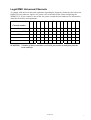
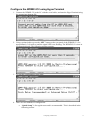
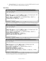
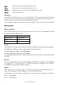
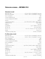
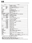
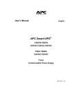
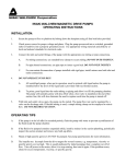
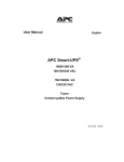
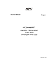
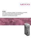
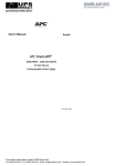
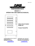
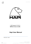
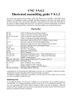
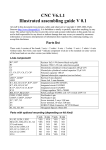
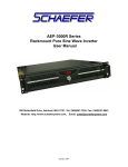
WDMX-512
user manual
Measurements are in millimeters.
WDMX512 Standard model
195
50
223
125
436
44
482
182
WDMX512 ProDiversity model
© 2003 Martin Professional A/S, Denmark.
This user manual has been developed by Blast Technology ApS, Denmark on behalf of Martin Professional A/S, Denmark.
All rights reserved. No part of this manual may be reproduced, in any form or by any means, without permission in writing from Martin Professional
A/S, Denmark.
The information contained in this document is subject to change without notice. Martin Professional AS makes no warranty of any kind with regard
to this material, including, but not limited to, the implied warranties of fitness for a particular purpose.
Martin Profession AS shall not be liable for errors contained herein or for incidental or consequential damages in connection with the furnishing,
performance or use of this material.
Part number 35000145, Revision D
Table of Contents
Introduction........................................................................................................... 5
Key features ..................................................................................................... 5
Included items .................................................................................................. 6
Safety information............................................................................................. 6
Protection from electric shock...................................................................... 6
Protection from safety and fire..................................................................... 6
Legal DMX Universes/Channels ....................................................................... 7
AC power............................................................................................................... 9
Mains ................................................................................................................ 9
Installation ........................................................................................................ 9
Wall mount........................................................................................................ 9
Fuses.............................................................................................................. 10
Power connection ........................................................................................... 10
Data...................................................................................................................... 11
DMX in............................................................................................................ 11
DMX out.......................................................................................................... 11
Tips for reliable data transmission .................................................................. 11
Configurations .................................................................................................... 13
Direct connection ............................................................................................ 13
Connection via an access point ...................................................................... 13
Configuring a WDMX-512................................................................................... 15
Pre-requisites ................................................................................................. 15
Connect the WDMX-512 to the PC ................................................................. 15
Prepare HyperTerminal .................................................................................. 15
Setup HyperTerminal manually ................................................................. 16
Setup HyperTerminal using sample files ................................................... 16
Configure the WDMX-512 using HyperTerminal............................................. 17
Quick Setup ............................................................................................... 18
Advanced Setup ........................................................................................ 19
Setup Access point ......................................................................................... 22
Operation............................................................................................................. 23
Guidelines....................................................................................................... 23
Resetting the unit............................................................................................ 23
Standard model operation .............................................................................. 23
PCMCIA WLAN card ................................................................................. 23
Operational indicators................................................................................ 23
Power LED.............................................................................................. 23
DMX LED ................................................................................................ 24
Transmitter LED ...................................................................................... 24
Signal strength LED’s.............................................................................. 24
ProDiversity model operation.......................................................................... 24
Antennas ................................................................................................... 24
Display....................................................................................................... 25
Display description .................................................................................. 25
Buttons ...................................................................................................... 25
3
Button description.................................................................................... 25
Standard model interfaces ................................................................................. 27
Top Panel........................................................................................................ 27
Power LED................................................................................................. 27
DMX LED ................................................................................................... 27
Transmitter LED ......................................................................................... 27
Signal strength LED’s................................................................................. 28
Rear panel ...................................................................................................... 28
Mains connector......................................................................................... 28
Fuses ......................................................................................................... 28
RS-232....................................................................................................... 28
DMX in ....................................................................................................... 28
DMX out ..................................................................................................... 29
PGM........................................................................................................... 29
Buttons....................................................................................................... 29
SET ......................................................................................................... 29
RST ......................................................................................................... 29
PCMCIA WLAN CARD............................................................................... 29
ProDiversity model interfaces ........................................................................... 31
Front Panel ..................................................................................................... 31
Display ....................................................................................................... 31
Display description .................................................................................. 31
Buttons....................................................................................................... 31
Button description.................................................................................... 31
Antennas.................................................................................................... 32
Rear panel ...................................................................................................... 32
Mains connector......................................................................................... 32
Fuses ......................................................................................................... 32
RS-232....................................................................................................... 32
DMX in ....................................................................................................... 32
DMX out ..................................................................................................... 33
PGM........................................................................................................... 33
Buttons....................................................................................................... 33
SET ......................................................................................................... 33
RST ......................................................................................................... 33
Specifications – WDMX-512 ............................................................................... 35
Standard model............................................................................................... 35
ProDiversity model .......................................................................................... 35
4
INTRODUCTION
Thank you for selecting the WDMX-512. The WDMX-512 comes in two models which will
function together in any combination:
•
WDMX-512 ProDiversity, a 19” rack 1 unit model with 2 external antennas, display and 8
control buttons.
•
WDMX-512 Standard, with internal antennas, mounting base for easy installation on
vertical and horizontal surfaces and LED indication.
All parameters, for both versions, such as transmitter/receiver option, WLAN channel and more are
easy to setup using a standard PC with serial port. On ProDiversity models, these options can also
be changed using the control buttons and display.
The WDMX-512 is expandable. Up to 13 WDMX sets (DMX-512 universes) or 6656 DMX
channels can operate within the same area.
The wireless DMX link operates on standard WLAN 802.11b protocol, ensuring flexibility, low
cost, instant compatibility and maximum performance. The WDMX-512 operates with or without a
standard WLAN access point.
The receiver is tolerant of any DMX input refresh rate and automatically truncates the output to
approx. 44 Hz and converts the output to standard DMX-512 (512 channels).
For the latest updates of product documentation and software, please visit the Martin web site at
www.martin.com.
Key features
All WDMX-512 models have the following features:
•
A DMX refresh rate of approx. 44 Hz on all 512 DMX channels.
•
Expandable up to 6656 DMX channels.
•
Transmits via radio signal -line of sight not required.
•
Multiple WDMX sets (DMX512 universes) can operate within the same area.
•
Works on 2.4 GHz license free band.
•
Operates on standard 802.11.b WiFi technology.
•
Converts any DMX signal from the receiver to standard DMX-512.
•
Diversity receiver, ensuring maximum performance and sensitivity.
ProDiversity models offer the following additional features:
•
Intuitive display indicating signal strength, DMX refresh rate, transmitter or receiver status
and usage of Access point.
•
Easy selection of channel, receiver/ transmitter mode and usage of Access point without
using a PC.
Introduction
5
•
External antennas ensuring longer range and enables optional use of remotely placed
antennas.
Included items
Unpack the package and inspect closely to make sure the following components are present:
•
WDMX-512 Standard or WMDX-512 ProDiversity.
•
SUBD 9 pole serial cable.
•
2 5-to-3 pole XLR converters.
•
PCMCIA WLAN card (only supplied with the Standard model)
•
Power cable
•
HyperTerminal Configuration diskette and CD
Safety information
Warning! This product is for indoor and professional use only. It is not for household use.
This product presents risks of lethal or severe injury due to fire, heat, electric shock, and falls. Read
this manual before powering or installing the unit, follow the safety precautions listed below and
observe all warnings in this manual and printed on the unit. If you have questions about how to
operate the unit safely, please contact your dealer.
Protection from electric shock
•
Disconnect the unit from AC power when replacing the fuses, or opening the device.
•
Always ground (earth) the unit electrically.
•
Use only a source of AC power that complies with local building and electrical codes and
has both overload and ground-fault protection.
•
Do not expose the unit to rain or moisture.
•
Refer any service operation to a qualified technician.
•
Never operate the unit with missing or damaged covers.
•
Replace the unit if it becomes defective or worn out, or before usage exceeds the maximum
service life.
Protection from safety and fire.
6
•
Never attempt to bypass the fuses. Always replace defective fuses with ones of the specified
type and rating.
•
Keep flammable materials well away from the unit.
•
Do not modify the unit.
•
Do not operate the unit if the ambient temperature (Ta) exceeds 40° C (104° F)
Introduction
Legal DMX Universes/Channels
To comply with the local rules and regulations regarding the frequency channels (also referred as
DMX-Universes) that are legal to use, please refer to the table below when configuring the
WDMX-512. If your country is not on the list, please consult the local authority for information
about the local rules and regulations.
DMX-universe/
1
2
3
4
5
6
7
8
9
10
11
12
13
Canada (IC)
X
X
X
X
X
X
X
X
X
X
X
-
-
North America (FCC)
X
X
X
X
X
X
X
X
X
X
X
-
-
Europe (ETSI)
X
X
X
X
X
X
X
X
X
X
X
X
X
France
-
-
-
-
-
-
-
-
-
X
X
X
X
Spain
-
-
-
-
-
-
-
-
-
X
X
-
-
Channel number.
WARNING: Violation of these restrictions can lead to prosecution or/and fines from the
local authority.
Introduction
7
AC POWER
WARNING! For protection from electric shock, the fixture must be grounded (earthed). The
AC mains supply shall be fitted with a fuse or circuit breaker and ground-fault
protection.
Important!
Verify the power supply setting before applying power.
Mains
Mains voltage and frequency for the WDMX-512 Standard and the ProDivisity:
US-model:
103VAC-125VAC
(50Hz-60Hz)
EU,SP,FR-model:
210VAC-250VAC
(50Hz-60Hz)
Installation
This device shall be located near the outlet socket. The outlet socket is functioning as the mains
disconnection device. Use only the mains cable included with the product.
Wall mount
When mounting the device on the wall, ensure appropriate fastening. The device must be fastened
so it can carry 5 times its own weight. Make sure that the device is only mounted in the orientation
illustrated above.
AC power
9
Fuses
• Standard models come with double pole/neutral fusing, located next to the power
connector, that protect both neutral and phase.
• ProDiversity models have a single fuse, accessible from the rear panel, that protects the
phase.
US-model:
125mA(T)/ 250VAC
EU,SP,FR-model:
63mA(T) / 250VAC
Never attempt to bypass the fuses. Always replace defective fuses with ones of the specified
type and rating.
Power connection
Important!
Connect the WDMX-512 directly to AC power.
If the product is not an US product, you need to install a cord cap that fits your supply on the
power cable. A 3-prong grounding-type plug must be installed following the manufacturer’s
instructions. The following table shows some possible pin identification schemes; if the pins
are not clearly identified, or if you have any doubts about proper installation, consult a
qualified electrician.
10
Wire Color
Pin
Symbol
brown
live
L
blue
neutral
N
yellow/gree
n
groun
d
PE
Data
DATA
The WDMX-512 has 5-pin XLR sockets for DMX input and for DMX output.
Connect a DMX control device to a WDMX-512 acting as a transmitter, and a DMX network with
DMX fixtures to a WDMX512 acting as a receiver.
DMX in
When configured as a transmitter, apply a 5 pins female XLR plug from a DMX master to this
input. Use the included 5 to 3 pole adaptor, if a 3 pins XLR cable is used.
If configured as a receiver, apply a termination of 120 ohm between pin 2 and pin 3 to this input.
Pin
Description
Pin 1
GND (shield)
Pin 2
Cold (-)
Pin 3
Hot (+)
Pin 4
No Connection
Pin 5
No Connection
DMX out
When configured as receiver, apply a 5 pins female XLR plug from this output to one or more
DMX devices. Use the included 5 to 3 pole adaptor, if a 3 pins XLR cable is used. Remember to
terminate the DMX link with a 120 ohm termination at the end of the link.
If configured as a transmitter, apply a termination of 120 ohm between pin 2 and pin 3 to this
output.
Pin
Description
Pin 1
GND (shield)
Pin 2
Cold (-)
Pin 3
Hot (+)
Pin 4
No Connection
Pin 5
No Connection
Tips for reliable data transmission
Use shielded twisted-pair cable designed for RS-485 devices: standard microphone cable cannot
transmit control data reliably over long runs. 24 AWG cable is suitable for runs up to 300 meters
(1000 ft). Heavier gauge cable and/or an amplifier is recommended for longer runs.
Do not overload the link. Up to 32 devices may be connected on a serial link.
Data
11
Terminate the link by installing a termination plug in the output socket of the last fixture. The
termination plug, which is a male XLR plug with a 120 ohm, 0.25 watt resistor soldered between
pins 2 and 3, “soaks up” the control signal so it does not reflect and cause interference. If a splitter
is used, terminate each branch of the link.
12
Data
CONFIGURATIONS
The WDMX-512 can be configured in two different ways:
1. Direct connection (also called ad-hoc network) where the transmitter communicates directly
to the receiver(s), or
2. Using an Access Point (also called an infrastructure network) where the transmitter
communicates to an AP that repeats the signal to the receiver(s).
Direct connection
This is the simplest way to transfer wireless DMX. The WDMX-512 transmits directly to the
receiver(s). This does not require an Access Point and is recommended for stable use. NOTE: The
WDMX-512 will work in any combination of the Standard and ProDiversity models.
WDMX-512 Standard/
ProDiversity
Receiver 1
WDMX-512 Standard/
ProDiversity
Transmitter
DMX Universe
1-13
WDMX-512 Standard/
ProDiversity
Receiver n
Connection via an access point
A way to increase the range is to use an Access Point between the transmitter and the receiver(s).
•
The Access Point repeats the wireless signal from the transmitter to the receiver, which
means that the range can be extended of up to twice the length.
•
Access Points are of different quality, be careful when selecting a type.
NOTE: The use of Access points is NOT recommended and is only included for user
flexibility. Access Points are 3rd party products and are NOT supported by Martin
Professional A/S.
WDMX-512 Standard/
ProDiversity
Receiver 1
WDMX-512 Standard/
ProDiversity
Receiver n
DMX Universe
1-13
DMX Universe
1-13
WDMX-512 Standard/
ProDiversity
Transmitter
Access Point
Configurations
13
CONFIGURING A WDMX-512
This chapter contains the following sections:
•
Pre-requisites
•
Connect the WDMX-512 to the PC
•
Prepare HyperTerminal
•
Configure the WDMX-512 using HyperTerminal on page 17
•
Setup Access point on page 22
Pre-requisites
You need a PC running HyperTerminal or another terminal program to configure a Standard model,
or to configure a ProDiversity model in advanced mode.
The ProDiversity model can be configured without HyperTerminal in normal mode using the
buttons on the front panel:
Toggles between normal and Access point mode.
Increments the current channel number by one.
Decrements the current channel number by one.
Toggles between receiver (Rx) and transmitter (Tx) mode.
Connect the WDMX-512 to the PC
Connect the 9-pole serial cable from the RS-232 port, on the WDMX-512, to a 9 pole serial port on
the PC. If there is only a 25 pole serial port available on your PC then a SUBD25 to SUBD9
converter can be used (not included).
Serial Cable
WDMX-512
PC
Prepare HyperTerminal
HyperTerminal is a standard terminal program included in Windows. HyperTerminal is used to
configure the WDMX-512. Before the WDMX-512 can be configured the HyperTerminal has to be
setup correctly. Other standard terminal programs can be used as well.
There are two ways to do it; the:
1. First is to set up HyperTerminal manually (not recommended)
Configuring a WDMX-512
15
2. Second, and easiest way is to copy the contents of the WDMX-512 setup diskette or CDROM to your local drive and double click on the appropriate sample setup file.
Setup HyperTerminal manually
1. Open HyperTerminal.
2. Create a "New connection" this can be done by clicking the Hypertrm.exe icon or via the
menu within HyperTerminal "File→New Connection".
3. Type in a name for the connection (for example, WDMX-512).
4. Under "Connect using" select "Direct to Com 2" if your available Com port is Com 2
otherwise select the appropriate Com port.
5. Set "Bits per second" to 115200.
6. Set "Data Bits" to 8.
7. Set "Stop Bits" to 2.
8. Set "Flow control" to None.
9. Click OK - the HyperTerminal screen should appear.
10. Select properties from the menu bar.
11. Under "File" menu select "Save As" and save the configuration file to a convenient folder.
You can create a shortcut to the configuration file and put it on the desktop. The configuration files
have a naming convention of *.ht where star is the name you chose when setting up the new
connection. For example, "WDMX-512.ht".
Setup HyperTerminal using sample files
1. Copy the files from the CD-ROM or diskette into a local folder on the PC. Do not execute
the file directly from the CD-ROM or floppy disk; it will result in an error message in
windows. There are four HyperTerminal setup files on the disk:
a. “WDMX512-COM1.ht” – use if WDMX-512 is connected to serial port number 1
b. “WDMX512-COM2.ht” – use if WDMX-512 is connected to serial port number 2
c. “WDMX512-COM3.ht” – use if WDMX-512 is connected to serial port number 3
d. “WDMX512-COM4.ht” – use if WDMX-512 is connected to serial port number 4
2. Execute the file that corresponds to the COM port connected to the WDMX-512. The *.ht
files on this media is a shortcut to HyperTerminal.
16
Configuring a WDMX-512
Configure the WDMX-512 using HyperTerminal
1. Connect the WDMX-512 to the PC with the serial cable, and start the HyperTerminal using
the appropriate shortcut file.
2. Using a pointed object, press the “SET” button on the rear panel of the WDMX-512, for
approximately 3 seconds or until the signal LED’s are flashing. The WDMX-512 is now in
configuration mode. The following window appears .
3. To start the configuration, press enter.
4. There are two methods of configuration:
a. “Quick Setup” is for regular users and is recommended. This is described in the
following section.
Configuring a WDMX-512
17
b. “Advanced Setup” is for experienced users only and is NOT intended for normal
users. This is described in Advanced Setup on page 19
Quick Setup
1. After selecting “Quick Setup” (Q) and pressing Enter, the following will appear:
2. Chose if you want the WDMX-512 to be a transmitter or a receiver (T or R). and press
Enter.
3. Specify which DMX universe is being used(1-13) and press Enter.
Note that only one transmitter is allowed to send on each DMX-Universe, and multiple
receivers are allowed to receive on each DMX-Universe.
18
Configuring a WDMX-512
4. Specify if you are using a standard Access Point (not included in this package) (Y/N)
5. The WDMX-512 is now configured and ready for use. You can exit HyperTerminal and
disconnect the WDMX-512 from your PC.
Advanced Setup
Advanced setup is ONLY for people with experience in wireless networking. This setup is made for
flexibility only and is not necessary to setup for the system to work.
When the ProDiversity model is configured with Advanced Setup, “Advanced Mode” will be
displayed on the first line of the unit’s display. To return to normal operating mode, configure the
device with quick setup using HyperTerminal. It is not possible to exit Advanced mode using the
buttons on the unit.
1. Select advanced setup
Configuring a WDMX-512
19
2. Specify if you want the WDMX-512 to be a transmitter or a receiver (T or R). and press
Enter.
3. Specifies the IP address for the remote WDMX-512 device. Press Enter, and the IP address
for the current device.. Both Unicast and Multicast IP addresses are valid.
4. Specifies what kind of network that is being used. Normally this will be an ad-hoc network,
but if an Access Point is used, choose infrastructure network.
5. Specify the channel (frequency) to transmit or receive on and press Enter. Please note that
only one transmitter is allowed to send on each channel (frequency), and multiple receivers
20
Configuring a WDMX-512
are allowed to receive on channel (frequency).
6. Type in the SSID network name that WDMX-512 is using and press Enter
7. The WDMX-512 is now configured and ready for use. You can exit HyperTerminal and
disconnect the WDMX-512 from your PC.
Configuring a WDMX-512
21
Setup Access point
When using a standard Access Point, as repeater, refer to the product user’s guide and configure it
with the following settings:
•
SSID in the AP has to be set to WDMX<DMX-Universe> e.g. WDMX7 for the WDMXUniverse 7 or WDMX2 for the WDMX-Universe 2.
•
Channel has to be set to the same number as the WDMX-Universe number on the WDMX512 (1-13).
No web-encryption or security settings should be used or enabled.
22
Configuring a WDMX-512
OPERATION
This chapter contains the following sections:
•
Guidelines
•
Resetting the unit
•
Standard model operation
•
ProDiversity model operation on page 24
Guidelines
To get the best performance out of the system, the following guidelines should be taken into
consideration.
•
Keep the transmitter and receiver as close as possible.
•
Obstacles like: walls, metal etc. reduces performance and range of the system.
•
Any objects less than 1 meter (3 feet) from the antennas will reduce performance and range,
so keep as clear as possible.
•
To achieve maximum range, keep the transmitter and receiver in the same level and in line
of sight.
•
Make sure to keep at least 2 bars in the signal strength indicator, to maintain a stable DMX
signal.
Resetting the unit
In the event of a disturbance or error it is possible to quickly reset the unit by pressing the:
•
Reset button on the front panel of the ProDiversity model
•
RST button on the back of the Standard model (with a pointed object)
Standard model operation
PCMCIA WLAN card
For operation insert the PCMCIA card into this socket. Do not use other WLAN cards than the
original type included in the WDMX-512 Standard package.
Remove the card form the unit when it is not in use or when the unit is being transported.
Operational indicators
Power LED
This LED indicates that power is applied to the WDMX-512.
Operation
23
DMX LED
When power is applied to the unit the DMX LED blinks as many times as the selected channel
number. If the unit is set to channel four, the LED will blink four times.
The DMX LED has the following functionality.
Configured as
Functionality
Transmitter
When configured as a transmitter the DMX LED
indicates that it’s transmitting the wireless DMX signal.
Receiver
When configured as receiver the DMX LED indicates
that it is receiving the wireless DMX signal.
Transmitter LED
Configured as
Functionality
Transmitter
When the LED is lit the WDMX-512 is configured as a
transmitter.
Receiver
When the LED is not lit the WDMX-512 is configured as
a receiver.
Signal strength LED’s
Configured as:
Functionality
Transmitter
-
Receiver
This indicates the receiving signal level.
NOTE:
1) If all the signal strength LEDs are flashing the WDMX-512 Standard is in configuration
mode.
2) If the signal strength LEDs are chasing, the WDMX-512 Standard has detected a WLAN Card
error.
ProDiversity model operation
Antennas
The WDMX-512 ProDiversity uses two external antennas. The two antennas should be connected
to the reversed TNC connectors on the front panel named: B (primary) and A (secondary). The
antennas operate in diversity mode, ensuring optimal sensitivity.
If operating by a single external antenna, antenna B should be used. This is the primary antenna.
24
Operation
Display
The display indicates the actual channel number, transmitter/ receiver status, access point mode and
the DMX refresh rate. It also shows the signal strength of the radio communication when in
receiver mode.
C h . : 1 0
Mo d e : R x
D MX : 4 4 H z
Display description
Antenna
Signal strength
N/A
Signal strength not available (e.g. in transmitter mode).
Access point mode
Ch.:
Current channel number/ universe.
Mode:
Rx: Receiver mode/ Tx: Transmitter mode
DMX:
DMX refresh rate.
--
No DMX input/ output.
??
Non standard DMX input/ DMX refresh rate truncated.
Buttons
The keyboard offers you easy access to set all parameters of the WDMX-512 ProDiversity, such as
channel number, transmitter/ receiver mode, access point mode, reset, display contrast and
backlight.
Button description
Turns the backlight on and off.
Toggles between normal and Access point mode.
Increases the contrast.
Decreases the contrast.
Increments the current channel number by one.
Decrements the current channel number by one.
Toggles between receiver (Rx) and transmitter (Tx) mode.
Resets the transceiver.
Operation
25
STANDARD MODEL INTERFACES
This section describes the user interface for the WMDX-512 Standard model.
Top Panel
Power LED
This LED indicates that power is applied to the WDMX-512.
DMX LED
When power is applied to the unit the DMX LED blinks as many times as the selected channel
number. If the unit is set to channel four, the LED will blink four times.
The DMX LED has the following functionality.
Configured as
Functionality
Transmitter
When configured as a transmitter the DMX LED
indicates that it’s transmitting the wireless DMX signal.
Receiver
When configured as receiver the DMX LED indicates
that it is receiving the wireless DMX signal.
Transmitter LED
Configured as
Functionality
Transmitter
When the LED is lit the WDMX-512 is configured as a
transmitter.
Receiver
When the LED is not lit the WDMX-512 is configured as
a receiver.
Standard model interfaces
27
Signal strength LED’s
Configured as
Functionality
Transmitter
-
Receiver
This indicates the receiving signal level.
NOTE:
1) If all the signal strength LEDs are flashing the WDMX-512 Standard is in configuration
mode.
2) If the signal strength LEDs are chasing, the WDMX-512 Standard has detected a WLAN Card
error.
Rear panel
Mains connector
This is the main power connection. For protection from electric shock, the unit must be grounded.
The color code for the power cord is:
Color
Description
Yellow/Green
Earth/Ground
Brown
Live
Blue
Neutral
Fuses
The WDMX-512 Standard comes with two fuses F1 and F2 that protects both neutral and phase.
The WDMX-512 ProDiversity has a single fuse F1 protecting the phase.
F1, (F2): 63mA (T) / 250V
(for 230V models).
F1, (F2): 125mA (T) / 250V (for 115V models).
Never attempt to bypass the fuses. Always replace defective fuses with ones of the specified type
and rating.
RS-232
This is a serial interface and is only used to configure the WDMX-512 Standard, and the WDMX512 ProDiversity in “Advanced mode”. For further details about the configuration see Configure
the WDMX-512 using HyperTerminal on page 17.
DMX in
When configured as a transmitter, apply a 5 pins female XLR plug from a DMX master to this
input. Use the included 5 to 3 pole adaptor, if a 3 pins XLR cable is used.
If configured as a receiver, apply a termination of 120 ohm between pin 2 and pin 3 to this input.
Pin
28
Description
Standard model interfaces
Pin 1
GND (shield)
Pin 2
Cold (-)
Pin 3
Hot (+)
Pin 4
No Connection
Pin 5
No Connection
DMX out
When configured as receiver, apply a 5 pins female XLR plug from this output to one or more
DMX devices. Use the included 5 to 3 pole adaptor, if a 3 pins XLR cable is used. Remember to
terminate the DMX link with a 120 ohm termination at the end of the link.
If configured as a transmitter, apply a termination of 120 ohm between pin 2 and pin 3 to this
output.
Pin
Description
Pin 1
GND (shield)
Pin 2
Cold (-)
Pin 3
Hot (+)
Pin 4
No Connection
Pin 5
No Connection
PGM
This is for service purpose only, and should NOT be connected.
Buttons
These “Pin buttons” are located next to the connectors. Due to security reasons these buttons can
only be activated by a paper clip or similar object.
SET
If this button is pressed for more than 3 seconds the WDMX-512 is in configuration mode and the
signal LED’s will be flashing/ display showing “Setup using serial port”. To cancel configuration
mode press RST or turn the power off and on.
RST
If this button is pressed the WDMX-512 will reset.
PCMCIA WLAN CARD
Insert the PCMCIA card into this socket (WDMX-512 Standard ONLY). Do not use other WLAN
cards than the original type included in the WDMX-512 Standard package. Remove the card form
the unit when it is not in use.
Standard model interfaces
29
PRODIVERSITY MODEL INTERFACES
The following chapter describes the user interface for the DMX-512 ProDiversity model.
Front Panel
Display
The display indicates the actual channel number, transmitter/ receiver status, access point mode and
the DMX refresh rate. It also shows the signal strength of the radio communication when in
receiver mode.
C h . : 1 0
Mo d e : R x
D MX : 4 4 H z
Display description
Antenna
Signal strength
N/A
Signal strength not available (e.g. in transmitter mode).
Access point mode
Ch.:
Current channel number/ universe.
Mode:
Rx: Receiver mode/ Tx: Transmitter mode
DMX:
DMX refresh rate.
--
No DMX input/ output.
??
Non standard DMX input/ DMX refresh rate truncated.
Buttons
The keyboard offers you easy access to set all parameters of the WDMX-512 ProDiversity, such as
channel number, transmitter/ receiver mode, access point mode, reset, display contrast and
backlight.
Button description
Turns the backlight on and off.
Toggles between normal and Access point mode.
Increases the contrast.
Decreases the contrast.
ProDiversity model interfaces
31
Increments the current channel number by one.
Decrements the current channel number by one.
Toggles between receiver (Rx) and transmitter (Tx) mode.
Resets the transceiver.
Antennas
The WDMX-512 ProDiversity uses two external antennas. The two antennas should be connected
to the reversed TNC connectors on the front panel named: A (primary) and B (secondary). The
antennas operate in diversity mode, ensuring optimal sensitivity.
If operating by a single external antenna, antenna A should be used, witch is the primary antenna.
Rear panel
Mains connector
This is the main power connection. For protection from electric shock, the unit must be grounded.
The color code for the power cord is:
Color
Description
Yellow/Green
Earth/Ground
Brown
Live
Blue
Neutral
Fuses
The WDMX-512 Standard comes with two fuses F1 and F2 that protects both neutral and phase.
The WDMX-512 ProDiversity has a single fuse F1 protecting the phase.
F1, (F2): 63mA (T) / 250V
(for 230V models).
F1, (F2): 125mA (T) / 250V (for 115V models).
Never attempt to bypass the fuses. Always replace defective fuses with ones of the specified type
and rating.
RS-232
This is a serial interface and is only used to configure the WDMX-512 Standard, and the WDMX512 ProDiversity in “Advanced mode”. For further details about the configuration see Configure
the WDMX-512 using HyperTerminal on page 17.
DMX in
When configured as a transmitter, apply a 5 pins female XLR plug from a DMX master to this
input. Use the included 5 to 3 pole adaptor, if a 3 pins XLR cable is used.
If configured as a receiver, apply a termination of 120 ohm between pin 2 and pin 3 to this input.
Pin
Description
Pin 1
GND (shield)
32
ProDiversity model interfaces
Pin 2
Cold (-)
Pin 3
Hot (+)
Pin 4
No Connection
Pin 5
No Connection
DMX out
When configured as receiver, apply a 5 pins female XLR plug from this output to one or more
DMX devices. Use the included 5 to 3 pole adaptor, if a 3 pins XLR cable is used. Remember to
terminate the DMX link with a 120 ohm termination at the end of the link.
If configured as a transmitter, apply a termination of 120 ohm between pin 2 and pin 3 to this
output.
Pin
Description
Pin 1
GND (shield)
Pin 2
Cold (-)
Pin 3
Hot (+)
Pin 4
No Connection
Pin 5
No Connection
PGM
This is for service purpose only, and should NOT be connected.
Buttons
These “Pin buttons” are located next to the connectors. Due to security reasons these buttons can
only be activated by a paper clip or similar object.
SET
If this button is pressed for more than 3 sec. the WDMX-512 is in configuration mode and the
signal LED’s will be flashing/ display showing “Setup using serial port”. To cancel configuration
mode press RST or turn the power off and on.
RST
If this button is pressed the WDMX-512 will reset.
ProDiversity model interfaces
33
SPECIFICATIONS – WDMX-512
Standard model
Mains inlet (US) ...........................................................103 VAC-125VAC, 50-60Hz(IEC Connector)
Mains inlet (EU,SP,FR) ...............................................210VAC- 250VAC, 50-60Hz(IEC Connector)
Power consumption ......................................................................................................................~10W
Current consumption (US) ........................................................................................................~80mA
Current consumption (EU,SP,FR)..............................................................................................~40mA
Protocol .................................................................................................................................. DMX512
Communication distance .............................................up to 200 m (666 ft), outdoor, without repeater
DMX Refresh rate ........................................................................................................... Approx 44 Hz
DMX I/O .............................................................................................................................. 5 pin XLR
Expandability ..........................................................................................up to 13 DMX-512 universes
WLAN Card ............................................................................................................802.11B, PCMCIA
Size (h, w, d) .................................................................... 50 x 195 x 125 mm (1.96 x 7.68 x 4.9 inch)
Weight ............................................................................................................................ 1.5 kg (53 oz.)
Temperature operating range ............................................................................. 0°-40° C (32°-104° F)
ProDiversity model
Mains inlet (US) ...........................................................103 VAC-125VAC, 50-60Hz(IEC Connector)
Mains inlet (EU,SP,FR) ...............................................210VAC- 250VAC, 50-60Hz(IEC Connector)
Power consumption ......................................................................................................................~10W
Current consumption (US) ........................................................................................................~80mA
Current consumption (EU,SP,FR)..............................................................................................~40mA
Power consumption ....................................................................................................................... 10 W
Protocol .................................................................................................................................. DMX512
Communication distance ..........................................up to 300 m (1.000 ft), outdoor, without repeater
DMX Refresh rate ........................................................................................................... Approx 44 Hz
DMX I/O ...............................................................................................................................5 pin XLR
Expandability ..........................................................................................up to 13 DMX-512 universes
WLAN Card ............................................................................................................802.11B, PCMCIA
Size (h, w, d) ................................................................ 44 x 482 x 182 mm (1.73 x 19.00 x 7.17 inch)
Weight .......................................................................................................................... 3.5 kg (124 oz.)
Temperature operating range ............................................................................. 0°-40° C (32°-104° F)
Specifications
35