1
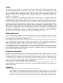
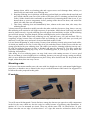
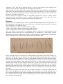
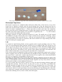
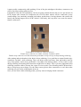
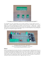
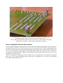
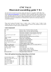
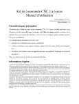
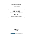
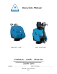
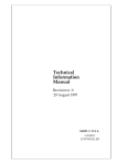
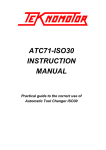
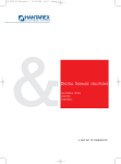
CNC V5.4.2
Illustrated assembling guide V 0.1.2
All stuff in this document (text, pictures, tables and whatever) is Copyright © 2005-2006, Paolo
Sancono. It is forbidden to totally or partially reproduce anything, by any mean. The author tried at
his best to provide correct and accurate information in this guide, but can not be held responsible for
any direct or indirect damage that may occur you caused by erroneous information or erroneous
interpretation of information here reported. By continuing reading, you accept this disclaimer.
Parts list
R1, R2
R3, R4
R5, R6, R7, R8, R9
R10
C1
C2, C3
C4
C5, C6, C7
D1, D2
LED1, LED2
LED3
Q1, Q2
IC1, IC2, IC3
IC4, IC5, IC6
IC7
RELAIS1, RELAIS2
CON1, CON2, CON3
X1, X2, X3
X4
X5
H1, H2, H3, H4, H5
1kΩ ¼ W Resistor (brown-black-red-gold)
3,3kΩ ¼ W Resistor (orange-orange-red-gold)
1kΩ ¼ W Resistor (brown-black-red-gold)
270Ω ¼ W Resistor (red-purple-brown-gold)
Electrolytic Capacitor 220 µF 25V Cylindrical Vertical Mount
Polyester Capacitor 100 nF Parallelepiped Shape
Electrolytic Capacitor 22 µF 16V Cylindrical Vertical Mount
Polyester Capacitor 100 nF Parallelepiped Shape
Fast Recovery Diode
Red Led, 5 mm Diameter
Green Led, 5 mm Diameter
BC547 Transistor
Integrated Circuit DIL18, type 1 – With a White Mark on it
Integrated Circuit DIL18, type 2 – Without the White Mark
78M05 Voltage Stabilizer
Relay package E3206S, coil: 12V contacts: 230V 5A
Pin-Header 6 pin
Screw Terminal 2 ways 5,08 mm
Screw Terminal 10 ways, 5,08 mm
SUBD-25 Male Connector, 90° PCB Mount
Hexagonal Spacers 10mm M3
Congratulations for Purchasing this high-quality electronic kit! Assembling it following step-bystep directions found in this guide will be fun and will make you proud!
Translation in English of this guide is incomplete, and some parts are still in Italian, but we are sure
you will successfully assemble your kit!
Soldering Iron
To assemble the board, you will need a soldering iron for electronics. Power should be between
15W and 40W, if it’s without temperature control, or any power, if it’s temperature controlled. You
can’t use a gun-shape 100W solder, which is suitable to solder connectors on speakers or other big
connectors but its strength is just too much to mount delicate electronic devices on PCBs. Excessive
heating can damage electronic components.
Solder
You will also need solder for electronics, in classical alloy Sn/Pb 60/40 and classical alloy
variations (Sn/Pg/Ag 60/38/2 Sn/Pb/Cu 60/38/2) or the new Lead-free alloys Sn/Ag 98/2 Sn/Sb
95/5 which melt at higher temperatures. You cannot use solder for pipes, of inferior quality and
purity and without alloy components needed to lower melting point to temperatures which don’t
damage electronic devices. We suggest a wire diameter of 0,7 0,8 or 1,0 mm; thicker diameters are
excessive for electronics.
Solder for electronic use is stuffed with flux inside, which serves to eliminate oxide from
components leads and board pads. While solder emits smoke, its flux is cleaning parts: smoke is
generated by flux, not by melting solder. Flux is necessary, because it cleans oxide, which is nonconductive and wouldn’t let the circuit work or would let it work worse because oxide doesn’t
conduct well electricity. If you solder with “old” solder, i.e. one which was not smoking any more,
and remained without active flux, your soldering may be good from a mechanical point of view
(parts remain on place) but bad from an electric point of view (soldering doesn’t conduct well), and
this may cause malfunctions. You have same kind of troubles if you didn’t heat enough pad on
board prior to putting solder onto it: solder doesn’t stick to the pad, but forms a sphere landing no
the pad, but not sticking to it (these are called cold solderings, and don’t conduct well). So be
extremely concentrated while soldering, to make each soldering a perfect one!
Other useful tools
You will find useful cutting-tweezers bent 45° degrees, to cut out components leads. Also long
tweezers are useful to handle small parts, and help you put components leads into holes on board.
Tweezers are extremely useful to mount jumpers.
Since board is not so small (100 x 160 mm), a “third hand” advice it is not strictly necessary for this
project. “Third hand” is a heavy base with two tweezers which can help at holding components and
small boards while soldering with the other two hands (one for soldering iron, the other for
soldering thread): indeed you would need 4 hands for a good soldering session!
You definitively won’t need soldering paste, which might be useful while desoldering components
from old boards with lot of dust and stains, of you are reworking old boards, but it is not needed for
new components and new boards mounting, for whom it is sufficient flux core present inside solder
thread, and more flux would be too much.
Printed Circuit Boards
On Printed circuit boards (the green-colored board is called this way) – PCBs for short – you may
identify a components side, the one with white serigraphies, where components will find room, and
a soldering side, the opposite one, where copper traces and pads are present. Copper traces are
protected by a green solder mask, which protects copper, and helps you out during soldering,
because solder won’t stick on solder mask, but will stick on pads, which are not covered by solder
mask, so you won’t mess with solder where it shouldn’t be.
Components are provided with leads which are to be inserted in holes already drilled on PCB. You
insert components from components side (the one with serigraphies), than flip-over the board and
solder leads to pads.
Soldering
Soldering consists of 3 phases to be done rapidly one after the other:
1. Put soldering iron tip at first on the board pad, heating it, and then also to the lead, heating
both of them. You should start from the pad because it’s bigger and needs more heat to
reach the same temperature as the component lead. Moreover, pad is linked to copper trace,
which will take away some of the heat provided, and also, over-heating components may
damage them, while over-heating pads and copper traces won’t damage them, unless you
insist really too much with your soldering iron.
2. Keeping soldering iron in position, still heating pad and lead, put solder thread onto lead and
pad. Smoke should come out of the solder at all times (flux is cleaning pad and lead from
oxide). Solder should stick confortable to pad and lead, connecting them: that is true if you
heated them at correct temperature before putting solder thread on them, and ended the
whole job while flux was still smoking.
3. Take away soldering iron and immediately later, almost at the same time, take away also
soldering thread.
3 phases must be performed so rapidly one after the other, and they last not so long, that we can say
that soldering well consists in one single sequence of operations, which doesn’t last long, but indeed
must be timed correctly. A good soldering post will appear clean and shiny at sight. A bad soldering
post will look opaque, irregular-shaped, and not sticked/glued to pad or component lead.
Some people put solder thread onto soldering iron tip, and then carry it to pad and lead. This is
completely wrong, because flux will smoke while on soldering tip, and by the time you reach pad
and lead, it’s all gone away and won’t clean pad and lead surfaces oxide.
It is true that at beginning of work session you may clean soldering iron tip using some fresh solder,
of which you intend to use flux. Let the flux do its job, and then remove solder excess with the wet
sponge provided with your soldering iron. The solder you used for cleaning soldering iron tip can’t
be used for soldering, because its flux is finished, and must be disposed of. You may repeat this
procedure (cleaning soldering tip) every 20 or 30 soldering posts, if your tip gets dirty and is not
soldering well anymore.
After doing 10 or so soldering posts, cut away lead excess with cutting tweezers: it’s not a good
idea to cut them to correct length prior to soldering, because you may get wrong, cutting too much,
and it is more difficult to hold components on place if they have shorter leads. So: keep leads at full
length, solder them, then cut away excess.
Mounting order
It is best to first mount smaller parts, the ones with less height on circuit, and mount higher/bigger
parts later, so that there are no totems in the way to reach the bottom of the board. Our suggestion is
to follow the order proposed in this guide.
IC sockets
The 6 DIL18 Sockets supplied with the kit
You will start with Integrated Circuits Sockets, among the shortest (as opposite to tall) components
in the kit, the ones which are also the easier to solder because of generous pads dimensions. A
number of 6 is to be mounted on circuit. These are all the same: DIL 18 (Dual In-line, 18 pin).
Please note that on one edge of sockets there’s a U sign: this must be oriented as shown in the
serigraphy. The U sign will be matched with the U sign on chips which will be inserted in the
sockets at a later time (after mounting and checking the whole board).
After inserting the sockets, hold them on place with a hand or by using a flat plate, and flip board
upside down, so that working desk or used plate will keep them on place. It’s easy for sockets to
come out from holes, because holes diameter is bigger than sockets’ leads. If sockets should come
outside, do all again by caring more.
For each socket, we suggest to solder two diagonally opposite pins, to keep it steady. Before
soldering all other pins, check if socket is down on the bottom of the board, other wise while
pressing ics inside you may force copper pads to dissect from the PCB.
Resistors
Resistors come in a cilindrical shape with 2 axial leads. Main (background) color is light brown. On
this background, 4 colored bands are drawn, which serve to identify nominal resistance. 10 resistors
are to be mounted, of 3 different values.
1kΩ (7 of them) have bands colored brown-black-red-gold
3,3kΩ (2 of them) have bands colored orange-orange-red-gold
270Ω (1 of them) have bands colored red-purple-brown-gold
Once you identify a resistor place on serigraphy, check the parts list (at the beginning of this
document) to know what value is to be mounted there. For example, R1 is 1kΩ resistor, so in R1
position you will mount a 1kΩ resistor, which you will recognize by its bands colors: brown-blackred-gold. Bands can’t be read back-order because last band is always gold.
Different ways of bending resistors and diodes leads
Before inserting resistors leads in holes in PCB, bend them at right angles and at right distance. For
sample for R1, R3, R7 holes are distant 7 mm, and leads should be bended right where cylindrical
body ends. For R4 holes distance is 10 mm, so leads should be bended 90° with a natural curvature.
For R5 and R8, holes distance is 12 mm, while for R9 it’s as big as 15 mm. Use tweezers to help
you bend at the right distance. Some resistors (R2, R6, R9) are to be mounted vertically. One lead
should be kept straight, the other should be bended 180°, so that resistor can fit in holes distant only
2,5 mm. Once you put a resistor in holes, open wide slightly leads on the other side so that, after
flipping upside-down the board, resistor doesn’t come out from the board and you can solder it.
Don’t open wide too much, otherwise it’s difficult to remove component in case you need to rework
the board.
Don’t insert all resistors at the same time, but just some of them (4 or 5 of them), solder them, cut
lead excess, and then insert some more resistors. This way leads won’t crowd soldering side of
PCB, making it difficult to reach pads with soldering iron and solder thread, due to leads in the way.
Don’t cut leads before soldering, because components may come out from the board by themselves,
since they have less anchoring.
Diodes
Diodes are similar to resistors, because have a cylindrical body, and axial leads, and are mounted in
the same way. However, you will need extra care with diodes, because while resistors are unpolarized parts and can be mounted in either verse of the two possible, diodes are polarized, and
you MUST mount them in the correct orientation. Just look at the different-color band on one side,
which is reported on serigraphy on board: just place the diode as shown on serigraphy. Supplied
diodes can be with orange body and black band on one side, or black body with silver or white band
on one side. In either case, just look at what edge the band is, and place the diode as shown on
serigraphy.
Jumpers
There are two jumpers to be soldered on the board. One, the shortest, is between IC1 and IC2. Bend
it at 90° with tweezers near one edge, put it in the hole, look at how long should it be, remove it
from the hole, and bend the other 90° curve with tweezers. Put it in the two holes, and pull from
other side with tweezers. Gently open wide from the other side so that jumper does not come out as
you flip top-down the board to solder jumpers lead on pads. After soldering, cut away lead excess
with cutters.
SUBD25 Connector
SUBD25 90° male connector fixes perfectly into 25 holes for pins and two bigger holes for fixing it
firmly. Be sure the connector entered completely in the board before soldering, because it’s
extremely difficult to push it down after you did some soldering, due to the high number of
soldering joints.
Soldering on these small pads is more difficult than for IC’s pads, because connector pins take away
heat, and pads are smaller. Be sure solder covered and jointed well both pin and pad. If you insisted
too much on a soldering post which isn’t developing well, and you put more solder because you
needed it’s flux, you may end up with too much “old” (inactive flux) solder in zone, and also a lot
of “old” solder on iron tip. Things get dirty because there’s no flux, and all this solder in zone
doesn’t leave room for the good soldering post you plan to do. In this case, clean the tip on sponge,
to remove all solder excess. Put the cleaned tip in the bad zone, and it should take away most of the
solder. Repeat once or twice if needed. Than start all over again with fresh solder. Sometimes when
you want to remove old solder, which tends to stick on place and doesn’t come away following a
clean soldering iron tip, it’s a good idea to start by adding a lot of new, fresh solder, which will help
at producing a single giant ball out of the old solder which will eventually fall away by itself if you
hold board vertically, and keep on heating and adding more solder.
Polyester Capacitors
Polyester capacitors are parallelepiped-shaped components, and white colored. 5 of them are to be
mounted on circuit, on C2 C3 C5 C6 C7 labeled posts. These capacitors are all the same: 100 nF
capacity. You won’t need any peculiar advice with these components, except the good old
suggestion of opening wide a little bit leads to help holding component on place while soldering it.
Don’t forget to remove excess lead with cutting tweezers (you might forget because they’re not so
long, but still need to be cut not to eventually get shorted with other leads after bending by
accident). Polyester Capacitors are un-polarized components as well, so you may orient them in one
of the two possible verses, and it would be the same for the circuit.
Electrolytic Capacitors (up, blue color) and Polyester Capacitors (down, white color)
Electrolytic Capacitors
Electrolytic Capacitors are cylindrical shape and can be black, blue, violet, brown, or any color!
Upper base of cylinder is metallic with pre-carved braking lines. From the bottom base the two
leads come out. Electrolytic capacitors are polarized components and must be oriented correctly on
board. On board’s serigraphy there a + (Plus) sign next to positive pole hole. On component,
positive pole lead can be recognized because it’s longer than negative pole one. If you happen to cut
the leads of the same length, negative pole can still be recognized by the “- - - - -” (a line of minus
signs) you find on the lateral side of the cylinder.
The bigger capacitor, of 220µF, should be mounted in C1 place. The smaller one, of 22µF, should
be mounted on C2 place. Please make sure to align correctly the two capacitors, following + (Plus)
sign on serigraphy. Please note that the two + signs are one opposite the other. A common mistake
is to orient correctly one of the two capacitors, and for the second one to align looking at the other
instead of looking at serigraphy again.
Led
Led stands for Light Emitting Diode, and are typically used to signal something to the user. They
come in a semi-transparent plastic package which lets you see produced light. You will get two red
and one green led with the kit. Red ones are to be mounted on LED1 and LED2 marked position
(the red leds will indicate relays activation), while green led is to be mounted on LED3 marked
position (and this one will indicate power present, when shining full-bright, and sometimes will
shine a little bit when there is no power present, but cable to PC is connected).
Leds are also polarized components. Positive pole has a longer lead than the negative pole, which is
shorter. Negative pole can also be identified by the straight beveling on that side. On serigraphy,
you won’t find a + (plus) and – (minus) sign, but the bevel on negative side, which should match
the bevel on component, corresponding to negative pole.
Depending on which kind of leds you received, there could be a diameter increase on leads 5 mm
away from the package. These will help mounting led 5 mm away from the board, so it can be seen
easier. If such diameter increase is not present in leds supplied, you may freely choose to mount
leds directly on board, or some millimeters far from it.
It’s easy to mount leds not perfectly vertical. You may fix them by heating soldering again and
orienting them correctly. You can do this fix only once or twice, if you insist, you should start
soldering procedure all again because you smoked away all remaining flux out of the solder. An
alternative, if lateral bending is not too much, is to straighten led by using tweezers. If led leads
were bent too much, it’s not a good idea to use tweezers because you may damage pad on the other
side, which may eventually break and dislocate from the board. First method is safer, even if it may
lead to start soldering all over (remove solder, and solder again).
Transistor (black, small), Red and green Leds, Voltage stabilizer IC7
Voltage Stabilizer
IC7 is a voltage stabilizer marked 78M05. This must be orientated correctly. On serigraphy one side
is drawn with thicker (bold) white border: towards that border you must orient the metallic side of
the component; opposites the plastic side.
Transistor
On Q1 and Q2 marked positions you will mount two BC547 transistors, which are easily
recognized by their distinctive half-moon shape. While inserting transistors, please don’t push them
all way inside holes, but leave them 10 mm away from the board. Transistors are in fact delicate
components and don’t like too much heating. 10 mm leads kept in free air will help to prevent
heating to arrive to the core of the device. For the same reason, it’s important to take some little
pause (10 seconds or so) between soldering a lead and the next one of the same transistor, so to let
device cool down a little beat. I’m not saying you will damage transistor at your first soldering on it,
or that you must be very quick: you may take all the time you need, but just keep in mind you can’t
stay with soldering iron forever on a transistor’s leg. If you realize you’re heating too much, take a
rest, and start again after some seconds, to let component cool down.
Central lead of transistors bended towards half-moon-shape side
Pin header connectors
6-ways pin-headers (male) connectors are to be mounted on CON1 CON2 CON3 marked positions
on the board. Holes are drilled with the exact size of pin-headers leads, so you must be extremely
cautious while gently pushing connectors in holes. You must not force it inside, otherwise some
leads can misalign with others due to excessive friction. Try to put all leads inside at the same time,
and no-one before the others, but all of them entering holes at the same time. It really helps to wave
it transversally continuously while pushing. If one of the pins misaligns with others, connectors can
still be fixed up working with tweezers.
It should be clear and self-explanatory, but let me point out that shortest side is to be put in holes in
PCB, longest side remains on component side of PCB where motors will be connected (it may
sound strange, but somebody mounted pin-headers upside-down, leaving shortest side outside the
board, and putting longest side in PCB’s holes!!! Obviously, this way there’s no room for motors’
female connectors).
Pin headers to solder on PCB (on left size)
Female strip connectors to solder on motor extention cables
Female strip connector inserted onto male pin-header to help it keep its shape during soldering.
After putting male pin-headers in the holes, before soldering, it’s a good idea to mount female stripconnectors on them while soldering. They will help to take heat away from pin-headers and far
away from plastic, and to keep pin-header of its shape. Pin headers plastic, in fact, tends to melt
during soldering iron heating and connectors might loose its shape. This is yet more important when
soldering extention cables, because the copper in wires needs a lot of heating and PCB board isn’t
there to help keep correct shape. For the same reason, please allow connectors to cool down after
soldering one pin, before soldering the next one.
Once you are done with 6 soldering points, you may remove helping female connector.
Once a pin-header has been soldered, remove female connector.
Please note that board in photography is a prototype, not the final industrial-quality board.
Screw terminals
On board you will also need to mount 3 two-ways screw terminals, and a 10-ways screw terminal.
Two-ways screw terminals are to be inserted on X1 X2 X3 positions. Pay attentions that the side
where you insert wires into should face the external boundary of the board, and not the interior part
of the board (it really sounds strange, but again some people mounted screw terminals backwards).
On X4 marked post, a 10 position long stripe of screw terminal is to be mounted. You should
assemble yourself the 10-ways terminal, by locking together some shorter terminals. You may
receive 2 3-ways terminals and 2 2-ways terminals, or 5 2-ways terminals. Whichever the case, just
link one to the others to form a longer stripe. Be sure to mount them by pushing all way down, so
that bottom surface is aligned among all the terminals. When using terminals, in fact, it is important
that the base is anchored to the board, because you will be exercising pressure with a screw driver
on them, and if they are not firmly based on the board, you may damage pads from the other side,
because leads would be pressed downway by the screw driver.
One ten ways screw terminal assembled with 2 3-ways and 2 2-ways screw terminals.
The other 3 2-ways screw terminals are to be used individually on the board.
On serigraphy next to X1 terminal (the power-in supply terminal) it is clearly marked 12V and “+”
(plus) and “-” (minus) marking to find out where to connect positive and negative pole of power
supply. To prevent reversing supply by accident, you may also write “+” (plus) and “-” (minus)
signs directly on terminal, with a lumocolor pen, just in case serigraphy gets removed by grasping.
The circuit is not protected from inverted polarity supply, and some components will get damaged if
you link a reversed-polarity supply to the board.
Assembling of board proceeds: almost done!
Please note that the board in photography is a prototype,
not the industrial-quality PCB you received.
Relays
Relays are the bigger parts on board, and in fact we mount them lastly. Leads disposition forces you
to mount them in the correct orientation. There are two relays in the kit, and they are to be mounted
on positions marked RELAIS1 and RELAIS2 on board. Your relays may differ in color or height
from the ones in photo, but will work the same. Also other components may come in different
colors (namely, screw terminals) but, again, they will do the same job. It depends on manufacturers,
which may sold out one kind and force me to supply the other one to you.
Relays shipped with kit
Hexagonal spacers
It is a nice idea to mount the 5 hexagonal spacers on the five suitable holes, so that soldering side of
the board won’t be accidentally damaged by irregular surfaces and a conductive object has less
chances to short traces. We suggest you mount the nut on component side, so that board can lean on
a flat surface, or can be fixed with M3 screws (not supplied) in the thread of the spacer. This way
you can fix the board on the bottom or on a side wall of your machine.
The 5 hexagonal spacers 10mm tall with M3 thread and relative nuts.
During normal usage of board, please be sure no metallic object can come in contact with traces
side, shorting out different zones of the circuit. For better protection you can fix PCB to a rigid
plate, such as another circuit board, a plastic or wooden plate (not supplied).
Check out soldering and polarity of polarized components
Please take your time to carefully inspect all soldering for omissions, short circuits, weak soldering
posts. It may happen to insert a component and forget to solder all its leads, to short two
consecutive pads with a solder drop, to do weak soldering, from a mechanical or electrical point of
view, and these will cause subtle malfunctions.
Before powering up the board, double check soldering side, and double check also correct
orientation of polarized components, such as diodes and electrolytic capacitors.
Hexagonal spacers mounted on board (nuts on component side) and perfect
soldering realized with professional solder and soldering iron.
Your soldering should look similar to this: shiny aspect, solder on the whole pad,
right amount of solder, regular shape, mechanical strength.
Insert Integrated Circuits into sockets
You may place integrated circuits in their sockets only after double checking the board for shorts or
missing soldering. Refer to U marking on one side to orient correctly IC’s. Before pushing/pressing
on the IC’s from above downway, control that pins are entering correctly the socket, because if a
pin is not really straight, it may happen that it bends badly while you are trying to insert a chip into
its socket. If a pin bends badly, chances are high that it can get broken when you try to fix it in its
original shape with tweezers.
There are two kinds of Integrated Circuits in this project. In positions IC1, IC2 and IC3 you should
place type 1 IC’s, the ones marked with a white spot. In positions IC4, IC5 and IC6 you should
insert un-marked (all-black) IC’s.
How the board will look once fully assembled.
Finished!
All done! Your board is ready. Just read user’s manual to start using it with satisfaction!