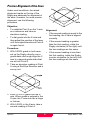
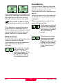
1
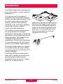
Leica Rugby 400 DG User Manual Version 1.1 English This manual contains important Safety Directions (refer to chapter Safety directions) as well as instructions for setting up the product and operating it. Read Carefully through the User Manual before you switch on the product. The symbols used in the User Manual have the following meaning: DANGER: Indicates an imminently hazardous situation which, if not avoided, will result in death or serious injury. WARNING: Indicates a potentially hazardous situation or an unintended use which, if not avoided, could result in death or serious injury. CAUTION: Indicates a potentially hazardous situation or an unintended use which, if not avoided, may result in minor or moderate injury and / or appreciable material, financial and environmental damage. ) Important paragraphs which must be adhered to in practice as they enable the product to be used in a technically correct and efficient manner. Product Identification The instrument model and serial number of your product are indicated on the label on the base of the unit. Enter the model and serial number in your manual and always refer to this information when you need to contact your agency or Leica Geosystems authorized service workshop. Type-Serial No.: 400-____________ Date of purchase:_____________ Rugby 400 DG 1.1.0en 2 Table of Contents Introduction .................................. 4 Features and Functions ............ 5 Operation ...................................... 6 Care and Transport .................. 23 Transport ..................................... 23 Storage ........................................ 23 Cleaning and Drying .................... 24 Entering Grade .............................. 6 Direct Grade Entry ....................... 6 Grade Entry by Digit .................... 6 Grade Zero .................................. 6 Grade Capability .......................... 6 Grade Swap................................. 7 Grade Matching ........................... 7 Identification of the Axes................ 8 Slope - Percent of Grade ............... 8 Alignment of the Axes.................... 8 Precise Alignment of the Axes....... 9 Safety Directions ...................... 25 General ........................................ 25 Intended Use ............................... 25 Permitted use ............................ 25 Adverse use............................... 25 Limits of Use ................................ 26 Responsibilities............................ 26 Warranty ...................................... 26 Hazards of Use ............................ 26 Laser classification ...................... 29 Labeling ....................................... 29 Electromagnetic Compatibility (EMC) .......................................... 30 Description................................. 30 Labeling Rugby 400 DG and Remote Control ........................... 31 Setup ............................................ 10 General Setup.............................. 10 Location ..................................... 10 Recommended Head Speeds ... 10 Tripod Setup .............................. 10 Setup Options .............................. 11 Head Speeds ............................. 12 H.I. (Height of Instrument) ......... 12 Automatic and Manual Mode: .... 12 Manual Mode with Grade .......... 12 Wind Sensitivity ......................... 13 Beam Masking ........................... 13 Additional Setup Options ............. 14 Technical Data ........................... 32 Checking Level Accuracy ....... 15 Checking Level Accuracy ............ 15 Checking the X-Axis .................. 15 Checking the Y-Axis .................. 15 Adjusting Level Accuracy............. 16 To Enter Adjustment Mode ........ 16 X-Axis Accuracy Adjustment ..... 16 Y-Axis Accuracy Adjustment ..... 16 Accessories ............................... 17 Batteries....................................... 17 The Sighting Scope ..................... 18 Remote Control............................ 18 Troubleshooting........................ 21 Display Screen Explanations ....... 21 Troubleshooting Suggestions ...... 22 3 Rugby 400 DG 1.1.0en Introduction The Rugby Grade laser is designed to serve your needs in a wide variety of applications. It is a proven tool for increased production with substantial reduction of labor, time and material costs. It can be used to accurately control land leveling, sloped or level grading, trenching, open cut mining, dredging, contouring of levees, general construction and excavation. Alignment is as easy as sighting over the top of the Rugby to your control point using the integrated alignment sights or the optional sighting scope assembly. For increased accuracy, follow the procedure for Precise Alignment of the Axes. This manual contains operating and set-up procedures for common applications. Its purpose is to describe the features of the Rugby and how the Rugby operates. The manual is not intended to describe specific applications. Contact your local dealer or Leica Geosystems for information specific to your jobsite requirements. The Rugby Grade lasers are rugged, accurate and fully electronic with an operating range up to 2,500 feet (770 meters) diameter. The Rugby 400DG is a dual grade laser and is capable of producing an accurate plane of laser light for applications that are level (1), single grade (2), or dual grade (3). Rugby 400 DG 1.1.0en 4 Introduction Features and Functions 8 12-volt input – Charge the batteries or run the Rugby directly from 12-volts. 1 POWER Button – Powers the Rugby on and off. 2 LCD Display – Shows the grade settings for the X and Y axes. The display shows also Beam Masking, Remote status, Battery status, H.I. and Head Speed. 9 Dual Batteries – The Rugby will run with one or two sets of batteries for maximum flexibility and battery life. 10 Raised alignment sights and mounting plate for the optional sighting scope. 3 X/Y Button – Press to set grade in the X and Y-axis. 4 UP Arrow Button – After pressing X/Y, press to increase the grade shown. 11 Easy grip handle for carrying and setup. 12 Tripod mount for attachment to a 5/8”-11 tripod. 5 STAR Button – Press to enter setup screens and the grade entry by digit screen. 6 DOWN Arrow Button – After pressing X/Y, press to decrease the grade shown. 7 Circular Level Vial – For initial setup reference. Features and Functions 5 Rugby 400 DG 1.1.0en Operation Entering Grade Grade Zero The grade in either axis can quickly be set to zero by pressing both the Up and Down buttons simultaneously while in either grade entry mode. Direct Grade Entry Press POWER to turn the Rugby on. When changing grade using the direct entry method, the counter will always stop at zero. Release the button and press again to continue counting beyond zero. Press X/Y once to enter Xaxis grade. Press X/Y again to enter Y-axis grade.The display will show the grade entry screens. Grade Capability The Rugby 400DG can have up to 15% grade simultaneously in both axes, or up to 25% in one axis. Grades above 15% in one axis require that the cross axis grade be ±1% or lower. In this situation, if attempting to enter grades greater than 1% or 15%, a notice will appear on the screen when the button is pressed. Use the UP or DOWN buttons to set the desired grade. Press X/Y to exit. Grade Entry by Digit While in the grade entry screens, press the STAR button and a cursor will appear on the +/- sign. Press the STAR button to move the cursor to the right. ) If no button is pressed, the display will revert to the main display after ten seconds. Press the UP or DOWN buttons to change the sign or the digit that is highlighted. Press X/Y to exit. Rugby 400 DG 1.1.0en 6 Operation Grade Swap Grade Matching The grade in the X and Y axes can easily be swapped from positive to negative in the Grade Entry by Digit screen. In Direct Grade Entry mode the movement of the leveling mechanism moves at the same speed as the grade counters. A typical application for this feature is road building. For example, with the Rugby setup on the crown of the road and with one axis aligned to the center line, the cross axis grade can be made to fall to the right or lefthand side simply by changing the +/- sign on the display. To match an existing slope, set up the laser over the known gradebreak (base) of the slope, and align the laser to the end of the slope with both control points parallel to the direction of grade. Adjust the Rod-Eye receiver on your grade rod for the elevation of the laser at the gradebreak next to the laser. Move the grade rod to a point on the slope that is too be matched. Then, dial grade into the laser until the RodEye indicates an on-grade reading. The percent of grade in the display is now equal to the grade being matched. Operation 7 Rugby 400 DG 1.1.0en Identification of the Axes Alignment of the Axes 1 X+ Axis – When positive grade is entered in the X-axis, grade will increase in this direction. When the desired grade is correctly set in the display, it is necessary to align the X and Y axes to the jobsite. 2 Y+ Axis – When positive grade is entered in the Y-axis, grade will increase in this direction. Ensure the circular level vial is positioned near the center of the circle for maximum self-leveling capability. 3 Front of Rugby – See also axis labeling on the sides of the laser and inside the top windows. Ensure the Rugby is properly positioned over a control point. Slope - Percent of Grade As shown, the direction of the X-axis is seen from the front of the Rugby, sighting over the top of the Rugby. Slope: The change in elevation per unit of measure (foot, meter, etc.) Rotate the Rugby slightly until the sights are aligned with your second control point. Percent of Grade: The change in elevation per 100 units of measure (feet, meters, etc.) Once aligned, work can begin. ) ) An optional sighting scope is also available. Calculating Percent of Grade from the Slope: Slope = 0.0059 Conversion = 0.0059 x 100 For very accurate alignment, refer to the steps for Precise Alignment of the Axes. Percent of Grade = 0.590% Rugby 400 DG 1.1.0en 8 Operation Precise Alignment of the Axes Under most conditions, the raised alignment marks on the top of the Rugby are adequate for alignment of the axes. However, for more precise alignment, use the following procedure. Objective: • • To establish Point A on the Y-axis as a reference and take an elevation reading. Alignment: To dial grade into the X-axis and then adjust the position of the laser until the original elevation at Point A is again found. • If the second reading is equal to the first reading, the X-axis is aligned correctly. • If the second reading is greater than the first reading, rotate the Rugby clockwise (to the right) until the two readings are the same. • If the second reading is less than the first reading, rotate the Rugby counter-clockwise (to the left) until the two readings are the same. Procedure: 1 With 0.000% grade in both axes, set up the Rugby directly over a grade stake and rough align the Yaxis to a second grade stake that we will call Point A. 2 Take an elevation reading at Point A using a Rod-Eye Receiver and a survey rod. 3 Enter +5.000% grade into the Xaxis. When grade is entered in the X-axis, the Y-axis acts like a hinge or fulcrum. 4 With 5.000% in the X-axis, take a second reading at Point A. Operation 9 Rugby 400 DG 1.1.0en Setup General Setup Tripod Setup Location Attach the Rugby securely to a tripod or laser trailer, or mount on a stable level surface. Make sure the location is clear of possible obstructions that may block or reflect the laser beam. Always check the tripod or trailer before beginning work. Make the most efficient use of the Rugby’s operating radius. The Rugby can be placed in the center of the working area or to one side. Make sure all screws, bolts, and nuts are tight. If your tripod has chains, they should be slightly loose to allow for thermal expansion during the day. Make sure the ground is stable. Ground vibration and extremely windy conditions can affect the operation of the Rugby. On extremely windy days, secure the tripod. Placing a sandbag on each leg can do this. (See also adjustment for setting the wind sensitivity of the Rugby.) If working in very dusty conditions, place the Rugby up-wind. The dirt and will then be blown away from the Rugby and reduce interference. If using a tripod with a quick disconnect adapter, point the control lever into the wind. This places the locking mechanism also into the wind, and will provide better stability. Recommended Head Speeds For surveying and manual machine control applications the typical head speed is 10 rps (600 rpm). For automatic machine control applications it is recommended to use the highest head speed, 20 rps, to increase the frequency of updates. When working at extended distances, decreasing the head speed (increasing the pulse time on the receiver) or changing the band width of the receiver to wide band can improve distance and performance. Rugby 400 DG 1.1.0en 10 Setup Setup Options Use the STAR button to select or deselect the setup parameters and exit the setup screen. Use the UP and DOWN buttons to move the cursor or change the selected parameter. The Rugby has several setup options that are easily accessed and changed in the first setup screen. From the main operating screen, Press STAR to access the setup screen. Press the Star button and the cursor will become a thick border around the selected parameter. Once selected, use the Up and Down buttons to change the parameter. Beam masking requires using also the X/Y button. Head Speed Selections – 5, 10, 15, 20 rps. With the beam masking option selected, press the X/Y button to turn the beam on or off in the selected quadrant. Use the Up and Down buttons to move around the quadrants. HI Function – Turns the H.I. function on and off. Automatic, Manual or Manual with Grade. Wind Sensitivity (1-5) – (1) for calm days, (3) for normal days, (5) for extremely windy days. Beam Masking – Turns the beam off in the selected quadrants. The quadrant will become solid and dark when selected for the beam to be masked (off) in the quadrant. Select the EXIT window, then press the Star button to exit and return to the main display. ) Changing the Setup Options: If no button is pressed, the display will revert to the main display after ten seconds. When entering the setup screen, the the EXIT window will be highlighted. To change the setup options in this window the buttons are used in the following way: Setup 11 Rugby 400 DG 1.1.0en The H.I. function becomes active 30 seconds after the unit has completely leveled and the head starts rotating. Head Speeds The Rugby can be set to any of four different head speeds – 5, 10 , 15, or 20 rps. (300, 600, 900, 1200 rpm) The H.I. function can be made to turn on automatically at power-up. This can be enabled in the second setup screen. Select the head speed that provides the best performance for your application. H.I. (Height of Instrument) Automatic and Manual Mode: The H.I. function is used to prevent elevation changes caused by movement of the tripod. The Rugby will always turn on in automatic mode and will continuously self-level to maintain grade accuracy. When the H.I. Alert function is activated, the self-leveling accuracy remains the same, but the self-leveling range of the Rugby is reduced. In manual mode the selfleveling function is turned off. The display screen will show the following: ) Movement of the Rugby beyond its self-leveling range will cause an “alert condition”. The Rugby will stop rotating and the following screen will appear on the display: The plane of laser light can be changed using the X/Y and arrow buttons, but the amount of change is not shown in the display. Stop the “alert condition” by pressing the Star or Power button and reset the function. Check carefully the setup and elevation of the unit to determine what has caused the alert condition. Adjust as required to the correct elevation. Manual Mode with Grade In Manual Mode with Grade, the display will alternately show the grade entered for the X and Y axes. The H.I. function can be turned on or off in the first setup screen. When the H.I. function is turned on, the letters “HI” will appear in the bottom, right part of the display. Rugby 400 DG 1.1.0en 12 Setup Beam Masking Electronic Beam Masking allows the operator to turn off the laser beam in specific quadrants to prevent interference with other operations on the job. In this mode, grade can be entered into either axis. The Rugby will self-level to the grade input in the unit, then will lock into manual mode at this grade. Using the setup menu, the beam can be turned off in up to three selected quadrants. ) When a quadrant is turned off, the space will appear dark. Once locked in manual mode the self-leveling function is turned off. The quadrants selected can be either diagonals of corners of the Rugby. This selection is made in the second setup screen. If it is desired to change the manual grade shown, a new grade can be entered (same as in automatic mode) and the Rugby will level to this new grade, then lock in manual mode. The settings for beam masking are normally not saved when the Rugby is turned off. The Rugby can be made to save the mask settings in the second setup screen. Wind Sensitivity The Wind Sensitivity setting allows the Rugby to operate in adverse environmental and windy conditions, while still ensuring maximum accuracy. The sensitivity numbers can be set from 1 to 5. Select “1” for calm conditions. Select “5” for very windy conditions. Use the lowest setting for conditions present. Setup 13 Rugby 400 DG 1.1.0en Changing the Setup Options: Additional Setup Options When entering the setup screen, the EXIT window be highlighted. Additional setup options may be accessed in a second setup screen. + To change the setup options in this window the buttons are used in the following way: From the main operating screen, Press and hold the UP button, then press the STAR button to access the second level setup screen. The STAR button is used to select or deselect the setup parameters. The UP and DOWN buttons are used to move the cursor and change the parameters. Press the STAR button and the cursor will become a thick border around the selected parameter. Once selected, use the UP and DOWN buttons to change the parameter. Selects beam masking at the diagonals or at the corners. Allows the Rugby to always start up with no beam masking, or to save and start up with the last beam mask setting used. Allows the Rugby to start up with the H.I. Alert automatically turned on, or turned off. Allows the operator to disable the negative grade function of the Rugby. When disabled, negative grade cannot be entered in the grade displays. The remote control is enabled only when a remote is to be used with the Rugby. It is normally off to conserve battery power. Rugby 400 DG 1.1.0en Select the EXIT window, then press the STAR button to exit and return to the main display. ) If no button is pressed, the display will revert to the main display after ten seconds. 14 Setup Checking Level Accuracy ) It is the responsibility of the user to follow operating instructions, and to periodically check the accuracy of the instrument and work as it progresses. ) The Rugby is adjusted to the defined accuracy specification at the factory. It is recommended to check your laser for accuracy upon receipt and periodically thereafter to ensure accuracy is maintained. If your laser requires adjustment, contact your nearest authorized service center or adjust the laser using the following procedure. Rotate the Rugby 180°, allow it to selflevel and then mark the opposite side of the X-axis (Position 2). ) Do not enter this mode or attempt adjustment unless you plan to change the accuracy. Accuracy adjustment should be performed only by a qualified individual that understands basic adjustment principles. Mark the position half-way between the two marks. The X-axis is within its accuracy specification if the two marks are within ± 1/16” (± 1.6 mm) from center. Checking Level Accuracy To check level accuracy of your Rugby, place the unit on a flat, level surface or tripod approximately 100 feet (30 meters) from a wall. 1 2 Checking the Y-Axis Checking the X-Axis Align the Y-axis by rotating the Rugby 90° so that the Y-axis is now square to the wall. Allow the unit to self-level completely, then check the Y-axis in the same way as above. Align the X-axis so that it is square to the wall. Allow the unit to self-level completely (approximately one minute after the unit begins to rotate), and then, using your Rod-Eye receiver, mark the position of the beam (Position 1). Checking Level Accuracy 15 Rugby 400 DG 1.1.0en Adjusting Level Accuracy Y-Axis Accuracy Adjustment To Enter Adjustment Mode If entered correctly, the Y-axis adjustment screen will appear. With the unit turned off, press and hold both the Up and Down buttons, then press the Power button to put the unit in adjustment mode. X-Axis Accuracy Adjustment Wait until the hour glass disappears before checking and changing the adjustment numbers. If entered correctly, the X-axis adjustment screen will appear. Use the Up and Down arrows to change the number and move the beam to the half-way point between the positions marked for the Y-Axis. Press the Star button to accept this position and accept the number in the display for the Y-Axis. When entering the adjustment screen, a small hour glass will appear. Wait until the hour glass disappears before checking and changing the adjustment numbers. Press the Star button again to accept, save, store the adjustment activity, and to return to the main display screen. Use the Up and Down arrows to change the number and move the beam to the half-way point between the positions marked for the X-Axis. Five counts in the display is equal to approximately 1/16” at 100 feet (1.6 mm at 30 meters). ) ) After adjustment, always check your work. Always check accuracy prior to critical applications. Repeated activation of the grade mechanism may result in accuracy variations up to ± 20 arc seconds. Press the Star button to accept this position and accept the number in the display for the X-Axis. ) Pressing the power button at any time before completing the procedure will revert the accuracy to previously saved information. Press the Star button again to move to the Y-Axis adjustment screen. Rugby 400 DG 1.1.0en 16 Checking Level Accuracy Accessories The Rugby can also be run directly from a 12-volt source through the charge jack. Batteries The unique battery solution in the Rugby has two independent battery compartments that will accept various combinations of NiMH packs or individual D-cell batteries (2). The battery status is displayed on power-up and as small icons on the main operating screen. Install the NiMH batteries (1) as shown on the label of the pack. Install individual D-cell batteries (2) as shown on the battery door cover. The charge jack (3) is located on the laser above the locking knob of the battery door (4). Charge time is approximately 4-5 hours. Accessories 17 Rugby 400 DG 1.1.0en The Sighting Scope Remote Control A sighting scope (739870) is available as an optional accessory for alignment of the axes and second day setups. The Rugby 400 DG Remote Control (739854) is a full functioning, twoway remote control. The scope is magnetically mounted to the top of the housing and once aligned has a repeatable accuracy of approximately ± 0.2°. The LCD display and the grade and star buttons on the remote are the same as on the Rugby. The Power button turns on only the remote. When pressed it will communicate with the Rugby to receive current information. Alignment of the crosshairs Once communication is established, the remote can be used to change grade and setup parameters on the laser. If using the scope for reference or second day setup, use the raised sights on the top of the laser to align your Rugby to a second control point. If the remote is not within range or otherwise loses communication, the the lost communication screen will be displayed. The scope is roughly aligned at the factory. If a more precise alignment is desired, first align the Rugby to a second control point using the procedure for Precise Alignment of the Axes found in this manual. It is important, to achieve specified distances, that the remote be used within the “line of sight” of the Rugby. A Press and hold the power button for 1.5 seconds to turn the remote off. A = Vertical crosshair alignment Rugby 400 DG 1.1.0en 18 Accessories Before you can use the remote it is necessary to enable the remote capability on the laser. The Standby button will cause the Rugby to go into standby mode for up to 16 hours. After this time the Rugby will shut off and can only be turned on again at the laser. To do this follow the instructions for entering and changing the setup in the second setup screen (page 14). When in standby mode the display will show only a sleeping Rugby. Change the remote symbol in the setup screen so that it no longer has a line through it. Pressing any button (except power) while the unit is in standby mode will cause the laser to return to normal operation. When enabled, the remote symbol will appear on the bottom of the main display. Programing the remote – To program the remote for your laser press and hold the STAR button, then press the POWER button. Automatic Shut Off - To conserve battery power, the remote will automatically shut off after two minutes of non-use. The remote will search the immediate area for Rugby units with remote capability, and will identify these in the display. Low Battery – The remote will display a low battery screen when the batteries have reached a voltage where the remote can no longer communicate with the laser. To select your laser highlight the serial number and press the STAR button. The remote will connect to the selected laser. To exit this screen without changing settings, highlight EXIT - NO CHANGE and press the X/Y button. To replace the batteries, remove the bottom cover of the housing. Install as indicated on the side of the housing. Accessories 19 Rugby 400 DG 1.1.0en Remote Notes Setting the shut-off timer – The remote is set from the factory to shut off after two minutes of not being used. To change this shut-off time, enter the remote programming screen (just described) by pressing and holding the STAR button, then pressing the POWER button. When the Rugby select screen is shown, press and hold the STAND-BY button for 1.5 seconds. The shut-off time will change between 120, 60, or 30 seconds each time the button is held. Backlighting – The LCD backlighting is normally off to conserve battery power. To backlight the display on the remote, press the power button a second time after the remote has been turned on. Remote reception – The remote is an RF (radio frequency) device with an internal antenna. Always ensure that the remote is within the “line of sight” of the Rugby. If the remote loses communication, hold the remote at a different angle to improve reception. Rugby 400 DG 1.1.0en 20 Accessories Troubleshooting Display Screen Explanations H.I. Alert Warning • Leica Start-up Screen • Can be programmed to display customer’s name and address. • • Battery Status Screen • • Displays on power-up Displays also when batteries are empty. Servo Limit Warning • • Automatic Mode • • Main Display Screen Unit automatically selflevels. • • Unit is tilted more than 30°. Temperature Warning Unit will not self-level Grade can be changed with the grade/arrow buttons. • • • Manual Mode with Grade • Unit is not level Check setup and circular level vial. Tilt Warning Manual Mode • • Unit has moved and elevation may have changed. Press Power or Star to reset H.I. function. Check unit’s elevation and adjust if required. Unit is too hot or cold to operate properly. Shade unit if too hot. Warm unit before continuing if too cold. Negative Grade Disabled Unit will self-level to grades input, then lock in manual mode. Grade can be changed with the grade/arrow buttons. • The ability to enter negative grade has been disabled in the second setup screen. Stand-by Mode Grade greater than 15% • • • Controlled by the stand-by button on the remote. Press the power button on the Rugby to turn off. • If attempting to enter grades greater than 15%, the cross axis grade is limited to 1%. Four similar screens are possible. Lost Communication • • Troubleshooting 21 The remote is out of range. Move closer. The remote is not in the line if sight of the laser. Rugby 400 DG 1.1.0en Grade stakes do not match the laser. • Check for proper alignment of the axes. Troubleshooting Suggestions Whenever there are questions regarding your laser, check the basics first. • Mode of operation - automatic, manual, manual with grade. • Battery status • Warning Screens - H.I., servo limit, temperature, adjustment. • Head speed setting • Beam mask setting Check level accuracy of the laser. • Check the grade stakes to verify their accuracy or to determine if they have moved. Beam masking not saved when laser is turned off. • Set up this preference in the second set-up screen. Remote will not turn on • Check and replace the batteries. No beam • The Rugby beam is infrared and invisible to the human eye. • • Remote will not communicate with the laser. • Check that remote capability is enabled on the laser. (see small icon on the main display) Check with a receiver to verify. No self-leveling • Check the basics above. Cannot change grade • Check the basics above. • Check remote battery status. • Reduce distance and try again. • Check the other axis. • • Check operation in manual mode. • Check if at grade limit. At longer distances, ensure the remote is in “line of sight” of the laser. • Reposition the remote at a different angle to improve the internal antenna reception. Loss of distance • Check the window surfaces. • Check with a different receiver. • At extended distances, decreasing the head speed may improve performance. ) If none of the above suggestions results in a solution, contact your local dealer or nearest authorized service center. Head rotates slowly • Check the basics above. • In low battery mode the Rugby will rotate slowly (7 RPS) to trigger the laser low battery function on the RE Pro. Rugby 400 DG 1.1.0en 22 Troubleshooting Care and Transport Transport Field Adjustment Transport in the field After transport inspect the field adjustment parameters given in this user manual before using the product. When transporting the product in the field, always make sure that you: • • Storage Either carry the instrument in its original transport case Product Respect the temperature limits when storing the product, particularly in summer if the instrument is inside a vehicle. Refer to “Technical Data” for information about temperature limits. Or carry the tripod with its legs splayed across your shoulder, keeping the attached instrument upright. Transport in a road vehicle Never carry the instrument loose in a road vehicle. It can be affected by shock and vibration. Always carry the product in its transport container and secure it. Field Adjustment Shipping Nickel-Metal Hydride Batteries When transporting the product by rail, air or sea, always use the complete original Leica Geosystems packaging transport container and cardboard box, or its equivalent, to protect against shock and vibration. • The storage temperature range is -40°C to +55°C (-40°F to +131°F). • We recommend storage in the temperature range from 0°C to +20°C (+32°F to +68°F), in a dry environment to minimize selfdischarge. • In the recommended temperature range, fully charged NiMH batteries can be stored for a maximum of 180 days. NiMH batteries must then be recharged again. • Remove the batteries from the product for storage. • After storage, recharge the battery before use. After long periods of storage inspect the field adjustment parameters given in this user manual before using the product. Shipping, transport of batteries When transporting or shipping batteries, the person in charge of the product must ensure that the applicable national and international rules and regulations are observed. Before transportation or shipping, contact your local passenger or freight transport company. Care and Transport 23 Rugby 400 DG 1.1.0en • Protect batteries from damp and wetness. Wet or damp batteries must be dried before storing or use. Cleaning and Drying Windows • Never touch the glass with your fingers. • Use only a clean, soft, lint-free cloth for cleaning. If necessary, moisten the cloth with water or pure alcohol. • Do not use other liquids; these may attack the polymer components. Damp Products • Dry the product, the transport container, the foam inserts and the accessories at a temperature not greater than 40°C / 108°F and clean them. • Do not repack until everything is completely dry. Cables and Plugs • Keep plugs clean and dry. • Blow away any dirt lodged in the plugs of the connecting cables Rugby 400 DG 1.1.0en 24 Care and Transport Safety Directions • Opening the product using tools, for example screwdriver, unless this is specifically permitted for certain functions. • Modification or conversion of the product. The person responsible for the product must ensure that all users understand these directions and adhere to them. • Use after misappropriation. • Use of products with obviously recognizable damages or defects. Intended Use • Use with accessories from other manufacturers without the prior explicit approval of Leica Geosystems. • Inadequate safeguards at the construction site (e.g. when using on or near roads). • Deliberate dazzling of third parties. • Controlling of machines, moving objects or similar monitoring application without additional control and safety installations. General The following directions should enable the person responsible for the product, and the person who actually uses the equipment, to anticipate and avoid operational hazards. Permitted use • • The product casts a horizontal laser plane or a laser beam for the purposes of alignment. The product can be set up on its own baseplate or on a tripod. • The laser beam can be detected by means of a laser detector. • The product, combined with machine control receivers, is also suitable for guiding construction machinery. • WARNING: Adverse use can lead to injury, malfunction, and material damage. It is the task of the person responsible for the equipment to inform the user about hazards and how to counteract them. The product is not to be used until the user has been instructed how to work with it. The product can be powered by rechargeable NiMH or alkaline batteries. Adverse use • Use of the product without instruction. • Use outside of the intended limits. • Disabling safety systems. • Removal of hazard notices. Safety Directions 25 Rugby 400 DG 1.1.0en Limits of Use Environment: Suitable for use in an atmosphere appropriate for permanent human habitation: not suitable for use in aggressive or explosive environments. To be familiar with local regulations relating to accident prevention; • To inform Leica Geosystems immediately if the product and the application becomes unsafe. WARNING: The person responsible for the product must ensure that it is used in accordance with the instructions. This person is also accountable for the training and the deployment of personnel who use the product and for the safety of the equipment in use. DANGER: Local safety authorities and safety experts must be contacted before working in hazardous areas, or in close proximity to electrical installations or similar situations by the person in charge of the product. Warranty Responsibilities International Warranty Manufacturer of the product The International Warranty can be downloaded from the Leica Geosystems AG home page at http:// www.leica-geosystems.com/ internationalwarranty or received from your Leica Geosystems dealer. Leica Geosystems AG, CH-9435 Heerbrugg, hereinafter referred to as Leica Geosystems, is responsible for supplying the product, including the user manual and original accessories, in a completely-safe condition. Hazards of Use Manufacturers of non-Leica Geosystems accessories WARNING: The absence of instruction, or the inadequate imparting of instruction, can lead to incorrect or adverse use, and can give rise to accidents with far-reaching human, material, financial, and environmental consequences. The manufacturers of non Leica Geosystems accessories for the product are responsible for developing, implementing and communicating safety concepts for their products, and are also responsible for the effectiveness of those safety concepts in combination with the Leica Geosystems product. Precautions: All users must follow the safety directions given by the manufacturer and the directions of the person responsible for the product. Person in charge of the product The person in charge of the instrument has the following duties: • • To understand the safety instructions on the product and the instructions in the user manual; Rugby 400 DG 1.1.0en 26 Safety Directions CAUTION: Watch out for erroneous measurements if the product has been dropped or has been misused, modified, stored for long periods or transported. WARNING: Inadequate securing of the work site can lead to dangerous situations, for example in traffic, on building sites, and at industrial installations. Precautions: Always ensure that the work site is adequately secured. Adhere to the regulations governing accident prevention and road traffic. Precautions: Periodically carry out test measurements and perform the field adjustments indicated in the user manual, particularly after the instrument has been subjected to abnormal use and before and after important measurements. CAUTION: If the accessories used with the product are not properly secured and the product is subjected to mechanical shock, for example blows or falling, the product may be damaged or people may sustain injury. DANGER: Because of the risk of electrocution, it is very dangerous to use grade rods and staffs in the vicinity of electrical installations such as power cables or electrical railways. Precautions: When setting-up the product, make sure that the accessories, for example tripod, tribrach, connecting cables, are correctly adapted, fitted, secured, and locked in position. Avoid subjecting the equipment to mechanical stress. Precautions: Keep at a safe distance from electrical installations. If it is essential to work in this environment, first contact the safety authorities responsible for the electrical installations and follow their instructions. CAUTION: During the transport, shipping or disposal of batteries it is possible for inappropriate mechanical influences to constitute a fire hazard. WARNING: By working during a thunderstorm you are at risk from lightning. Precautions: Before shipping the product or disposing of it, discharge the batteries by running the product until they are flat. When transporting or shipping batteries, the person in charge of the Precautions: Do not carry out field work during thunderstorms. Safety Directions 27 Rugby 400 DG 1.1.0en product must ensure that the applicable national and international rules and regulations are observed. Before transportation or shipping contact your local passenger or freight transport company. WARNING: If the product is improperly disposed of, the following can happen: • If polymer parts are burnt, poisonous gases are produced which may impair health. WARNING: Using a battery charger not recommended by Leica Geosystems can destroy the batteries. This can cause fire or explosions. • If batteries are damaged or are heated strongly, they can explode and cause poisoning, burning, corrosion, or environmental contamination. Precautions: • By disposing of the product irresponsibly you may enable unauthorized persons to use it in contravention of the regulations, exposing themselves and third parties to the risk of severe injury and rendering the environment liable to contamination. Only use chargers recommended by Leica Geosystems to charge the batteries. WARNING: High mechanical stress, high ambient temperatures or immersion into fluids can cause leakage, fire or explosions of the batteries. Precautions: The product must not be disposed with household waste. Precautions: Protect the batteries from mechanical influences and high ambient temperatures. Do not drop or immerse batteries into fluids. Dispose of the product appropriately in accordance with the national regulations in force in your country. WARNING: Short circuited battery terminals can overheat can cause injury or fire, for example by storing or transporting in pockets if battery terminals come in contact with jewelry, keys, metallized paper or other metals. Always prevent access to the product by unauthorized personnel. Product specific treatment and waste management information can be downloaded from the Leica Geosystems home page at http:// www.leica-geosystems.com/treatment or received from your Leica Geosystems dealer. Precautions: Make sure that the battery terminals do not come into contact with metallic objects. Rugby 400 DG 1.1.0en CAUTION: Only Leica Geosystems authorized workshops are entitled to repair these products. 28 Safety Directions Laser classification Labeling The rotating laser Rugby 400 DG produces an invisible laser beam that emerges from the rotating head. The product is a Class 1 laser product in accordance with: • IEC 60825-1 (2001-08): Safety of Laser Products" • EN 60825-1:1994+A11:1996+A2: 2001: “Safety of Laser Products” Class 1 laser products are safe under reasonable foreseeable conditions of operation and are not harmful to the eyes provided that the products are used and maintained in accordance with the instructions. Maximum radiant power: 1.7 mW (Rotating mode) Max. radiant power per pulse: N/A Pulse duration: N/A Pulse repetition frequency N/A Beam divergence: 0.2 mrad Measurement uncertainty: ±5% Class 1 Laser Product according to IEC 60825-1 (2001 - 08) A = Laser Beam Safety Directions 29 Rugby 400 DG 1.1.0en Precautions: Electromagnetic Compatibility (EMC) Use only the equipment and accessories recommended by Leica Geosystems. When combined with the product, they meet the strict requirements stipulated by the guidelines and standards. When using computers and two-way radios, pay attention to the information about electromagnetic compatibility provided by the manufacturer. Description The term Electromagnetic Compatibility" is taken to mean the capability of the product to function smoothly in an environment where electromagnetic radiation and electrostatic discharges are present, and without causing electromagnetic disturbances to other equipment. CAUTION: Disturbances caused by electromagnetic radiation can result in errorneous measurements. WARNING: Electromagnetic radiation can cause disturbances in other equipment. Although the product meets the strict regulations and standards which are in force in this respect, Leica Geosystems cannot completely exclude the possibility that the product may be disturbed by very intense electromagnetic radiation, for example near radio transmitters, two-way radios or diesel generators. Although the product meets the strict regulations and standards which are in force in this respect, Leica Geosystems cannot completely exclude the possibility that other equipment may be disturbed. CAUTION: There is a risk that disturbances may be caused in other equipment if the product is used in conjunction with accessories from other manufacturers, for example field computers, personal computers, two-way rradios, nonstandard cables or external batteries. Rugby 400 DG 1.1.0en Precautions: Check the plausibility of results obtained under these conditions. WARNING: If the product is operated with connecting cables attached at only one of their two ends, for example external supply cables, interface cables, the permitted level of electromagnetic radiation may be exceeded and the correct functioning of other products may be impaired. 30 Safety Directions Precautions: Labeling Rugby 400 DG and Remote Control While the product is in use, connecting cables, for example product to external battery, product to computer, must be connected at both ends. WARNING: Electromagnetic radiation can cause disturbances in other equipment, in installations (e.g. medical ones such as pacemakers or hearing aids) and in aircraft. It can also affect humans and animals. Precautions: Although the product meets the strict regulations and standards which are in force in this respect, Leica Geosystems cannot completely exclude the possibility that other equipment may be disturbed or that humans or animals may be affected. • Do not operate the product in the vicinity of filling stations or chemical installations, or in other areas where an explosion hazard exists. • Do not operate the product near to medical equipment. • Do not operate the product in aircraft. • Do not operate the product for long periods with it immediately next to your body. WARNING: Changes or modifications not expressly approved by Leica Geosystems for compliance could void the user's authority to operate the equipment. Safety Directions 31 Rugby 400 DG 1.1.0en Technical Data The Rugby 400 DG Operating range...................................................... 1,250 ft (385 meter) radius Self-leveling accuracy* ........................... ±1/16” at 100’ (1.5 mm at 30 meters) Self-leveling range ...................................................................................... ± 5° Grade Capability ............................. -5% to +15% in either axis simultaneously ...................................................... Up to +25% with up to ±1% in the cross axis Head Speeds ........................................................................ 5, 10, 15, 20 RPS Laser Diode Type ................................................................. 780 nm (invisible) Laser Classification............................................................. Class 1 IEC60825-1 Operating Temperature .......................................... -4° to 122°F (-20° to 50°C) Storage Temperature (without batteries) .............. -40° to 158°F (-40° to 70°C) Battery Life**................................ 65 hours (4-alkaline), 130 hours (8-alkaline) ...........................................50 hours (1-NiMH pack), 100 hours (2-NiMH packs) Charging time .............................................................. 4.5 hours (approximate) Dimensions (HWD) ............................ 10.4 x 10.2 x 7.9” (265 x 260 x 200 mm) Weight without batteries ............................................................ 11.1 lbs. (5 kg) Water resistance.................................................. Waterproof to IPX7 Standard Rugby 400 DG Remote Distance....................................................................... 200’ (60 meters) typical Battery type............................................................ Four AAA-alkaline batteries Size............................................................ 6.1 x 2.8 x 1.8” (155 x 70 x 45 mm) Weight....................................................................................... 14.4 oz. (410 g) * Accuracy defined at 25°C. ** Battery life is dependent on many variables. Rugby 400 DG 1.1.0en 32 Technical Data Rugby 400 DG and RF Remote Conformity to national regulations: • • FCC Part 15 (applicable in US) Hereby, Leica Geosystems AG, declares that the Rugby 400 DG, RF Remote is in compliance with the essential requirements and other relevant provisions of Directive 1999/5/EC. The declaration of conformity may be consulted at http://www.leica-geosystems.com/ce. Class 2 equipment according European Directive 1999/5/EC (R&TTE) for which following EU Member States apply restrictions on the placing on the market or on the putting into service or require authorization for use: • France • Italy • Norway (if used in the geographical area within a radius of 20km from the centre of Ny-Ålesund) • The conformity for countries with other national regulations not covered by the FCC part 15 or European directive 1999/5/EC has to be approved prior to use and operation. Frequency range...................................................................... 2402 - 2480 MHz Transmission power............................................................. < 100 mW (e.i.r.p.) Antenna Rugby 400DG .............................................................................. Chip Antenna Remote ........................................................................................ Chip Antenna Specific Absorption Rate (SAR) The product meets the limits for the maximum permissible exposure of the guidelines and standards, which are force in this respect. The product must be used with the recommended antenna. A separation distance of at least 20 centimeters should be kept between the antenna and the body of the user or nearby person within the intended application. Technical Data 33 Rugby 400 DG 1.1.0en Rugby 400 DG 1.1.0en 34 Technical Data Technical Data 35 Rugby 400 DG 1.1.0en Leica Geosystems AG, Heerbrugg, Switzerland, has been certified as being equipped with a quality system which meets the International Standards of Quality Management and Quality Systems (ISO standard 9001) and Environmental Management Systems (ISO standard 14001). 741895-1.1.0en Printed in Switzerland - Copyright Leica Geosystems AG, Heerbrugg, Switzerland 2007 Original text Total Quality Management Our commitment to total customer satisfaction. Ask your local Leica Geosystems agent for more information about our TQM program. Leica Geosystems AG CH-9435 Heerbrugg (Switzerland) Phone +41 71 727 31 31 Fax +41 71 727 46 73 www.leica-geosystems.com