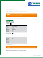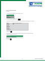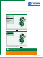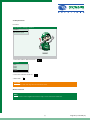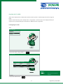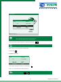
1
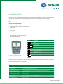
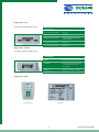
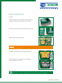
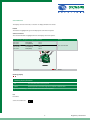
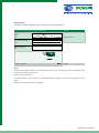
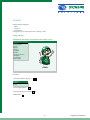
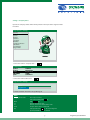
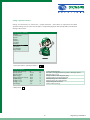
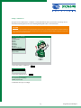
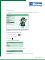
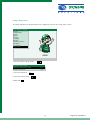
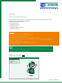
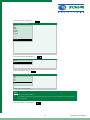
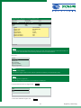
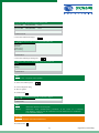
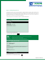
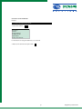
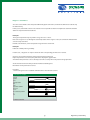
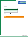
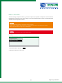
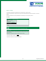
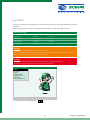
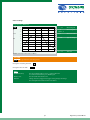
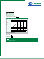
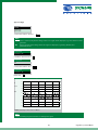
User‘s Manual
mega macs 50
HBMM50V3200EN1207S0
CONTENTS
Subject
Section
Device description
Views
B
Keypad
B
Changing the batteries
B
C
Screen functions
Settings
Display
D1
Company data
D2
Version
D3
Update
D4
Interface
D5
Language
D6
Batteries
D7
System parameters
D8
Simulation
D9
D10
Test function
D11
Diagnosis folder
Diagnosis
Control unit communications
E
Reading/deleting fault codes
F
Reading parameters
G
Actuator
H
Service reset
J
Basic settings
K
Coding
L
Multimeter
Settings
M
Two-channel
M
Temperature
M
Component measurement
M
Diagnosis folder
Description
N
General
Preliminary remark
O
Data protection
O
Exclusion of liability
O
Safety
O
Maintenance and care
O
Disposal
O
Page
3—4
3
5
6 — 7
8
9 — 10
11
12 — 15
16 — 20
20
21
22
23
24
25
26 — 30
31 — 32
33 — 35
36
37 — 38
39
40
41 — 47
48
49 — 50
50
51 — 52
53
53
54
55 — 56
56
56
Device DESCRIPTION
mega macs 50 is a portable diagnostic device for the identification and rectification of faults in vehicle electronic
systems. This manual contains a detailed explanation as to its use etc. All the illustrations are examples.
Uses
Control unit communications:
• Reading/deleting fault codes
• Reading parameters and present in graphic form
• Actuator test
• Service reset
• Basic settings
• Coding
Measuring functions:
• Voltage, current, resistance, temperature
• Two-channel multimeter
Key
Function
Print
PRINT
ESC
F1
mega macs 50 TFT display and keypad
Escape/return
F2
F3
Function keys
Cursor up/down
Cursor to the right
Cursor to the left
ENTER key
ON/OFF
On/off switch
> Print <
If mega macs 50 is connected to a PC, data can be transmitted and printed out. The >Gutmann Portal< programme
must be installed on the PC (see section D4).
Printing
Print window
The current window will be printed
Diagnosis folder printer
The diagnosis folder is opened, and the selected diagnosis printed.
Diagnosis folder e-mail
Not yet released
Remote support enquiry
Not yet released
Start remote
Linked to Gutmann >Remote< programme
Send protocol data
Not yet released
mega macs 50 Section B 1/3
mega macs 50 - Top
Connecting sockets from left to right
Connections
Test connection, minus
Channel 2
Test connection, plus
Channel 2
Diagnostic connection
ST2 for diagnostic cable and current clamp
Test connection, plus
Channel 1
Test connection, minus
Channel 1
mega macs 50 - Bottom
Connecting sockets from left to right
Connections
Mains
Power supply unit and charger
USB device
PC connection for data update and communication with PC programs
USB host
External hardware activation
Serial interface
RS232
mega macs 50 - Back
Extending support
Rating plate
mega macs 50 Section B 2/3
Changing the rechargeable batteries
Procedure:
1.Switch off mega macs 50 and remove all connecting leads.
2.Remove the protective casing, starting at the narrow end.
3.Remove six fastening screws using a suitable tool, e.g. >PH1<.
4.Open up the back panel to the right.
CAUTION
Do not pull off any cable plugs.
5.Carefully lever off the plastic cover using a suitable tool.
6.Replace the batteries, pay attention to correct polarity.
7. Reassemble in the reverse order.
NOTE
Recycle used batteries in accordance with the applicable environmental and disposal regulations.
mega macs 50 Section B 3/3
Screen functions
The display consists of a header, a selection- or display window and a footer.
Header
The header is highlighted in green and displays the current menu option.
Selection window
The selection window is highlighted in blue and displays the menu options.
mega macs 50 > Diagnosis > Peugeot > 306 Diesel
Header
306 1.9 D
306 1.9 D
306 2.0 D HDI
306 1.9 TD
306 1.9 D
Selection window
WJY (DW8)
DJZ (XUD9Y)
RHY (DW10TD)
DJY (XUD9A)
WJZ (DW8)
00-01
93-00
99-01
94-99
98-00
F3 Search
Footer
Checking display
Checking display functions
red
No connection with external systems
yellow
External systems connected, mega macs ready for communication.
green/yellow flashing
Active communication with external systems
Use
Procedure:
Select and confirm line.
mega macs 50 Section C 1/2
Display window
The display window is highlighted in blue and depicts all values and information.
mega macs 50 > Diagnosis > Peugeot > 306 Diesel
Header
Speed
rpm
870
Display window
Coolant temperature °C
69.0
Brake light switch
Off
F1 Info F3 Channel
Footer
Footer
The footer indicates the significance of the function keys. Keys F1, F2 and F3 bring up a text corresponding to the
selected menu, explaining its function.
Example: F1 Info, F3 Channel
A selection window is opened with the F2 menu function key. Functions are called up according to the menu
option.
Example: F2 zero balance, zero line and trigger.
mega macs 50 Section C 2/2
SETTINGS
All the programs required to
• adjust
• check and
• install updates
to mega macs 50 are stored in the main > Settings < menu.
Settings > Display <
The brightness of the display can be adjusted in the > Display < menu.
mega macs 50 > Settings
Display
Company data
Version
Update
Interface
Language
Batteries
System parameters
Simulation
Test function
Diagn. folder
Procedure:
1. Select and confirm > Display < .
Brightness
Brighter
Darker
2. Select brighter/darker.
3. Change setting: press and hold key.
4. Return with
ESC
mega macs 50 Section D1 1/1
Settings > Company data <
Input of the company address which will be printed on the report of the diagnosis folder.
Procedure:
mega macs 50 > Settings
Display
Company data
Version
Update
Interface
Language
Batteries
System parameters
Simulation
Test function
Diagn. folder
1. Select and confirm > Company data < .
Company data
Helligkeit
Name 1
Name 2
Street
POSTCODE
Town
Autohaus
Mustermann
Bergstrasse 5
79XXX
Somewhere
2. Select and confirm address box.
mega macs 50 > Settings
Helligkeit
Street
Bergstrasse 5
F1 Delete F3 Return Enter Enter Accept UP Keypad
NOTE
Hihghlighted in blue Mark
F1
F3
Enter
UP
This entry is marked.
Cancel the marking with key
with keys.
Deletes the marked entry.
Deletes all entries to the left of the mark.
Accepts all the entries in that field.
Corresponds to the key. The virtual keypad is opened, marked entries are deleted.
mega macs 50 Section D2 1/2
4. Open the virtual keypad.
ABCDEFGHIJKLMNOPQRSTUVWXYZ
abcdefghijklmnopqrstuvwxyz
1234567890 . , - + / % & < > ( ) ; :
_ äÄöÖüÜß
Street
Bergstrasse 5
Using the keypad
Select character
Accept character
Space
4. End input.
Underscore before the umlauts in the bottom line
ESC
5. Accept address box.
Info message
Accept settings conclusively?
ENTER (Yes) ESC (No)
6. Confirm message accordingly.
7. Enter inputs into the other address boxes as described above.
8. Return to main menu with 2 x
ESC
The inputs are stored and can be printed out on the diagnosis folder report.
10
mega macs 50 Section D2 2/2
Settings > Version <
All the information required to identify mega macs 50 is stored here.
Helligkeit
Versions
Overview
Software
Data
Design
Hardware
Device No.
Serial No. 1.40.xx 32.05.xxx
1.4 (31.xxx)
1.xx
12xx 12xx Program
Data version
Circuit
Housing
Customer assignment
Production assignment
In the event of a fault, these data will be required by Hella Gutmann Solutions.
CAUTION
It is not possible to update mega macs 50 without the device number.
11
mega macs 50 Section D3 1/1
Settings > Update <
Hella Gutmann Solutions makes an updatefor mega macs 50available to the customer twicea year. These updates are
subject to a charge. They cover not only new vehicle systems, but also technical modifications and improvements.
We recommend keeping your mega macs 50 up to date through regular updating.
Requirements
•
•
•
•
•
Web compatible PC
A cleared partner licence A or B from Gutmann Messtechnik
> Gutmann Portal < programme installed on the PC
Free USB interface on the PC
Power supply from mega macs 50 via power supply unit
NOTE
Data transmission can be made with a USB cable or with Gutmann > air macs <.
CAUTION
Depending on the type of transmission, the corresponding settings must be done in mega macs 50 and in the
> Gutmann Portal < programme on the PC.
Steps applicable to the PC:
1. Start the internet browser on the PC.
2. Start the > Gutmann Portal < on the PC.
3. Select > Gutmann Update < in the header and confirm.
CAUTION
Determine the desired interface in the > Settings < menu.
12
mega macs 50 Section D4 1/4
4. Select and confirm > mega macs 50 <.
5. Confirm message > Click here to ... <.
The PC is set up for data transmission.
13
mega macs 50 Section D4 2/4
Procedure applicable to mega macs 50
1. Connect mega macs 50 to a 220 V socket by way of the power supply unit.
CAUTION
During an update, mega macs 50 must be supplied with power through the power supply unit and must not
be disconnected from the power source during the update.
2. Switch on mega macs 50 and call up the > Settings < > Update < menu
Update
Update
System check
3. > Update <
Data transfer ..., data check
Helligkeit
Action
:Start with ENTER
Interface
:USB
File name
:xxxxx
File size
:123563
:23456
File bytes
Update size
:1257693576
Total files
:245
Faulty files
:xxx
4. Start the update.
5. > Update successfully completed < is displayed at the end of the update.
Action
Interface
File name
File size
File bytes
Update size
Total files
Faulty files
Update successfully completed
USB
xxxx
0
6. Switch off mega macs 50.
CAUTION
In every case disconnect mega macs 50 from external power supply, power supply unit or diagnostic plug.
All the new data will be available when mega macs 50 is started next time.
14
mega macs 50 Section D4 3/4
Fault messages after the update
Procedure:
1. Select and confirm > Update < in the > Settings < menu.
Update
Update
System check
System update
2. Select and confirm > System check <.
3. The system check will be carried out automatically and the table below displayed on completion.
Action
Interface
File name
File size
File bytes
Update size
Total files
Faulty files
A:\DADLxx.DEF
4. Return with
Update successfully completed
USB
xxxx
1
ESC
If the >Faulty files< entry is greater than 0, update the system with the >System update< menu.
Follow the instructions on the screen.
Info message
System files successfully updated.
On restarting, the files will be active.
Return with
ESC
15
mega macs 50 Section D4 4/4
Settings >Interface<
The interfaces required for communication with a PC are determined and set in this menu.
mega macs 50 > Settings
Display
Company data
Version
Update
Interface
Language
Batteries
System parameters
Simulation
Test function
Diagn. file
1. Select and confirm > Interface <.
mega macs 50 > Settings
Interface
RS232
USB
Wireless
2. Select and confirm > RS232, USB or Wireless <.
NOTE
The fastest and most reliable interface is USB.
CAUTION
If RS232 is selected, the baud rate must be set. The baud rates of mega macs 50 and PC must be the same. If
Wireless is selected, > air macs base < must be connected to the PC.
16
mega macs 50 Section D5 1/5
Set RS232 baud rate
Procedure:
mega macs 50 > Settings > Interface
Interface
RS232 baud rate
Wireless PC search
1. Select and confirm > RS232 baud rate <.
Baud rate
9600
19200
38400
57600
115200
2. Select and confirm the baud rate.
3. Return with
ESC
caution
The baud rates of PC and mega macs 50 must be the same.
Wireless PC search
note
The connection can be sought in this menu to verify a secure connection via Wireless.
17
mega macs 50 Section D5 2/5
Procedure applicable to the PC
1. Connect > air macs base < to the PC.
2. Start > Gutmann Portal < on the PC.
3. Select and confirm > Settings <.
4. Select and confirm > Change <.
5. Select and confirm > Wireless <.
6. Return with
ESC
18
mega macs 50 Section D5 3/5
Procedure applicable to mega macs 50
mega macs 50 > Settings > Interface
Interface
RS232 baud rate
Wireless PC search
1. Select and confirm > Interface <.
Interface
RS232
USB
Wireless
2. Select and confirm > Wireless <.
mega macs 50 > Settings > Interface
Interface
RS232 baud rate
Wireless PC search
3. Select and confirm > Wireless PC search <.
Info message
Searching for Wireless PC (takes approx. 1 minute). Please wait.
19
mega macs 50 Section D5 4/5
This message appears after a short time:
Info message
Wireless PC found and established as reciprocal.
4. Confirm message.
The data transmission via Wireless is set up.
Fault message
Info message
No device with Wireless found.
5. Check connection and installation of > air macs base < on the PC.
Settings > Language <
Selection of the desired language for mega macs 50.
note
Multiple languages on the device are an optional feature.
Appropriate information can be obtained from Gutmann Messtechnik.
20
mega macs 50 Section D5/D6 5/5
Settings > Batteries <
The nominal capacity of the installed batteries is set in the > Batteries < menu. The set value affects the charging
process and the display showing the state of charge of the battery. A value of 1500 mAh is set ex works.
caution
Incorrect inputs will lead to faulty charging processes which will affect the operating reliability of mega macs 50.
mega macs 50 > Settings
Display
Company data
Version
Update
Interface
Language
Batteries
System parameters
Simulation
Test function
Diagn. folder
1. Select and confirm > Batteries <.
Battery capacity (mAh)
1500
2. Put in the values via the virtual keypad (see section D2).
21
mega macs 50 Section D7 1/1
Settings >System parameters<
Voltage- and current data are stored in the > System parameters < menu which are required for the reliable
operation of mega macs 50. In the event of a fault, a corresponding diagnosis of the possible fault can be obtained
relating to these values.
mega macs 50 > Settings
Display
Company data
Version
Update
Interface
Language
Batteries
System parameters
Simulation
Test function
Diagn. folder
1. Select and confirm > System parameters <.
System parameters
Helligkeit
Battery state of charge
Battery current
Battery voltage
OBD voltage
Power supply unit voltage
UPOW voltage
Voltage + 17 V
Voltage + 3.3 V
ST2 voltage
2. Return with
45
731.98
11.54
13.80
15.32
14.53
16.90
3.38
2.37
< 15%: connect charger
Pos. value = charging current, neg. value = discharge current
Nominal value 9 – 12 V
Voltage at PIN 16 of the diagnostic plug
Charging voltage of power supply unit
Auxiliary voltage for communication
Auxiliary voltage for communication
Supply voltage for electronics
Internal auxiliary voltage
%
mA
V
V
V
V
V
V
V
ESC
22
mega macs 50 Section D8 1/1
Settings > Simulation <
A program can be called up in the > Simulation < menu, with which the user can practise the use of mega macs 50.
The simulation facility applies to the use of > Reading/deleting fault codes < and > Parameters <.
caution
If a vehicle is connected when the simulation function is active, no communication will be established with the
selected system. The displayed values will be incorrect. The simulation function will no longer be active when
mega macs 50 is started next time.
mega macs 50 > Settings
Display
Company data
Version
Update
Interface
Language
Batteries
System parameters
Simulation
Test function
Diagn. folder
1. Select and confirm > Simulation <.
Simulation
On
Off
2. Select and confirm function.
Info message
Accept setting conclusively?
ENTER (Yes) ESC (No)
3. Confirm the message accordingly.
23
mega macs 50 Section D9 1/1
Settings > Test function <
If no communication with the vehicle system is established, the function of the diagnostic plug can be checked
with this program.
mega macs 50 > Settings
Display
Company data
Version
Update
Interface
Language
Batteries
System parameters
Simulation
Test function
Diagn. folder
Procedure:
Connect the power supply unit to mega macs 50.
1. Select and confirm > Test function <.
2. Connect ST2 cable to mega macs 50.
3. Continue with
The following messages may be displayed:
Info message
A fault has occurred
Line:
Range:
Number:
Nominal level
Actual level
A
1
1
1
0
The diagnostic plug, connecting cable or mega macs 50 is defective,
or
Info message
Test successfully completed
mega macs 50 is OK.
The diagnostic socket in the vehicle is defective, e.g. no voltage at pin 16 or poor earth at pin 4
24
mega macs 50 Section D10 1/1
Settings > Diagn. folder <
The settings with which the diagnosis folder can be configured are stored in the > Diagn. folder < menu.
mega macs 50 > Settings
Display
Company data
Version
Update
Interface
Language
Batteries
System parameters
Simulation
Test function
Diagn. folder
1. Select and confirm > Diagn. folder <.
Diagnosis folder settings
Print out company data as well:
Database connection
yes
Local
2. Select and confirm box.
3. Select and confirm setting.
4. Return with
ESC
25
mega macs 50 Section D11 1/1
DIAGNOSis
Diagnosis > Control unit communications <
Control unit communication enables data exchange with the system to be tested by using a diagnostic device.
Communication is required for the following functions:
• Reading out/clearing fault memory
• Displaying parameters
• Carrying out actuator test
• Installing basic settings
• Carrying out coding of control units
• Carrying out service reset
caution
Faultless communication is possible only when:
· all the pins are correctly assigned at the diagnostic socket
· the vehicle has been correctly identified
· Identify the vehicle as precisely as possible by reference to the search mask
· the voltage of the vehicle‘s electrical system is not lower than 11.5 V; if necessary, use external power supply
· all power consumers are off
· the diagnostic plug is connected to the vehicle
· external accessories, radio, CD changer etc. are correctly connected
· the ignition is turned on
note
Always turn off the ignition before connecting or disconnecting the diagnostic plug to/from the vehicle!
If you wish to read out several fault memories one after the other one vehicle, turn off ignition after every readout
procedure and turn on again for the next procedure.
Procedure:
1.Switch on mega macs 50 with
ON/OFF
mega macs 50
Diagnosis
Multimeter
Diagn. folder
Settings
26
mega macs 50 Section E 1/5
2. Select and confirm > Diagnosis <.
mega macs 50 > Diagnosis
Alfa
Audi
BMW
Chrysler
Citroen
Daewoo
……..
……..
…….
Peugeot
3. Select and confirm > Manufacturer <.
mega macs 50 > Diagnosis > Peugeot
Petrol
Diesel
4. Select and confirm > Fuel <.
mega macs 50 > Diagnosis > Peugeot
104
106
206
207
306
307
F1 Put in licence plate number.
note
F1
Put in licence plate number.
To identify the vehicle in the diagnosis folder, put in the licence plate number via the virtual keypad
(see section D2).
5. Select and confirm > Vehicle Group <.
27
mega macs 50 Section E 2/5
mega macs 50 > Diagnosis > Peugeot > Diesel > 306
306 1.9 D
WJY (DW8)
00-01
3061.9 D
DJZ (XUD9Y
00-01
306 2.0 D HDI
RHY (DW10TD)
99-01
xxxxx
xxxx
xxxxx
xxxx
xxxxx
xxxxx
Model
306 2.0 D HDI
Engine code
RHY (DW10TD)
Model year
99-01
Rated output
66 kW
Displacement
1997 cc
Type key number
884
Gutmann number
756
F3 search
note
A bright information window will appear for about 15 seconds giving data relating to the marked vehicle. F3
Search opens a window with search criteria by which the vehicle can be identified.
Press >F3<.
Model
Engine code
Model year
Rated output
Type key number
Diagn. programme
note
Re: > Type key number <
The first three digits in box 2.2 of the vehicle registration document, part 2 (for Germany only).
note
Re: > Diagnostic programme <
Possible types of diagnosis for the selected vehicle are displayed.
6. Search criterion, in this case engine code
Header
DHY
RHY
WJY
7. Select and confirm the engine code.
28
mega macs 50 Section E 3/5
mega macs 50 > Diagnosis > Peugeot > Diesel > 306
306 2.0 D HDI
RHY (DW10TD)
99-01
306 2.0 D HDI
RHY (DW10TD)
99-01
306 2.0 D HDI
RHY (DW10TD)
99-01
F1 Info F3 Search
8. Select and confirm vehicle type
… > Peugeot > Diesel > 306 > 306 2.0 TD HDI/RHY (DW10TD)
Fault code
Parameters
Actuator
Service reset
Basic setting
F3 Connection
9. Select and confirm type of diagnosis.
… > Diesel > 306 > 306 2.0 TD HDI/RHY (DW10TD) > Fault code
Motor
ABS
Airbag
F3 Connection
note
F3 Connection Diagnostic socket position
10. Select and confirm system.
11. Connect diagnostic plug.
12. Turn on ignition.
13. Continue with > 306 > 306 2.0 TD HDI/RHY (DW10TD) > Fault code > Engine
EDC15c2 (B)
F1 Info F2 Info
note
F1 Info F2 Menu
Information about the selected system.
Information about communication parameters. In the event of a complaint, uses this information for fault identification and rectification.
Hella Gutmann
Leave information with ESC.
caution
Changes to the data can lead to malfunctions.
14. Continue with 29
mega macs 50 Section E 4/5
caution
Follow the instructions on the screen without fail.
15. Continue with
> Fault code > Engine > Init vehicle *********
Lucas DCN2
Communication with the control unit is established.
For further information, refer to the sections on types of diagnosis.
30
mega macs 50 Section E 5/5
Diagnosis > Reading/deleting fault code <
If, during the internal check, the control unit identifies a component function as faulty, a fault code will be set in
the memory and the corresponding warning lamp activated. Mega macs 50 delivers the fault code in plain text.
In addition, information as to the possible effects and causes of the fault code is stored. If tests are required as to
possible causes, a connection can be made to the multimeter.
1. Connect mega macs 50 as described in section E to establish communication..
> 306 > 306 2.0TD HDI > Fault code > Engine
Number of faults: 3
Fault code: 832
CAMSHAFT SENSOR
Fault code: 560
PRIMARY CIRCUIT, FUEL PUMP
Fault code: 545
ACCELERATOR PEDAL SENSOR 2
F1 System info F3 Delete ENTER Details
2. Select and confirm > Fault code <.
note
F1 System info Information on the installed system if supported by the manufacturer.
Delete F3 All displayed fault codes will be deleted.
ENTER details Information about the marked fault will be displayed.
> 306 > 306 2.0TD HDI > Fault code > Engine
Fault code 832
FAULTY CAMSHAFT SENSOR
FAULTY SIGNAL
FUNCTION:
The sensor detects the camshaft position; the ignition and injection systems
are synchronised and/or the position of the variable camshaft control
detected via the signal.
EFFECT:
Poor starting behaviour, etc.
CAUSE:
>>> Circuit interruption/short circuit
F3 Delete fault F3 Menu
All the information can be displayed by scrolling.
31
mega macs 50 Section F 1/2
Connection to the multimeter
Example:
>>> Circuit interruption/short circuit
1. Select and confirm.
Voltage
Resistance
Current
Voltage/Voltage
Voltage/Current
Temperature
Comp. measurement
For instructions on using the multimeter, see section M.
2. Return to the desired menu option with
ESC
32
mega macs 50 Section F 2/2
Diagnosis > Parameters <
Since the causes of faults can be interpreted differently by the control unit, it is often not sufficient to read out only
the fault memory.
In many cases, either fault codes are not entered or it is not possible to obtain an unequivocal statement about the
defective component from the fault text.
Example 1:
The engine temperature may vary within a range of -30°C to +120°C.
If the sensor signals +9.0°C, although the actual temperature in the engine is +80°C, the control unit will determine
an incorrect injection time.
No fault code will be set, as this temperature is logical for the control unit.
Example 2
Fault text: Lambda probe signal faulty
In both cases, a diagnosis can only be carried out if the corresponding parameters are read out.
mega mac 50 reads the parameters out and presents them in plain text.
If up to 4 parameters are selected, they will also be displayed in graphic form.
A maximum of 8 parameters can be called up, but in this case they will not be presented in graphic form.
A task-orientated selection of the parameters facilitates fault diagnosis.
Information on the parameters is stored.
Procedure
1. Connect mega macs 50 to establish communication as described in section E.
> Parameters > Engine
Speed
1/min
870
Fuel pressure
bar
280
Injection volume
mm_/H
11.7
Accelerator position
%
35
F1 Info F3 Channel
33
mega macs 50 Section G 1/3
note
F1 Info Information about the selected parameter is displayed.
Info Channel
Speed
Fuel pressure
Injection quantity
Accelerator position
2. Select and confirm > Parameters <.
Info Parameters
Accelerator position
An accelerator pedal potentiometer signals to the control unit …
Display Explanation
% Values in per cent
note
F3 Channel
Selection window with all the parameter groups.
Hella Gutmann Solutions has prepared a preliminary selection for certain diagnostic tasks.
By selecting one group, you can call up the parameters required for the diagnosis.
Group selection
All parameters
Basic function
Engine Start
xxxxxx
3. Select and confirm > Group <.
Channel selection
1
Speed
3
TV - angle
5
Air mass
6
Coolant temp.
8
Lambda vltg.
B1
B2
B2
B3
B7
1/min
°
°C
mV
F1 Help F2 Deselect F3 Nominal values
Procedure:
1. >F2< deselects all the parameters marked *.
2. Mark parameters.
3. Deselect or select parameters with .
4. Renewed establishment of communications
ESC
note
If more than eight parameters are selected, observe the info message.
Info message
- Parameters are not presented in graphic form.
- The measured values will not be stored in the diagn. folder.
34
mega macs 50 Section G 2/3
note
F3 Nominal values
Nominal values for the parameters can be called up depending on manufacturer.
Channel selection
1
Speed
3
O2 Integrator
5
Air flow meter
6
Coolant temp.
8
Lambda vltg.
F1 Help F2 Deselect F3 Nominal values
rpm
°
°C
mV
Procedure:
1. Mark parameter, in this case speed.
2. Press >F3<.
Speed
Vehicle-specific data
Engine at operating temperature, idling 710 - 890 1/min
Possible faults:
- Idle actuator or TV actuator faulty
- xxxxxx
3. Return with
ESC
35
mega macs 50 Section G 3/3
Diagnosis > Actuator <
Components in electronic systems are activated with the > Actuator < menu. Therefore it is possible to check the
basic functions and cable connections of these components.
DANGER
To prevent damage to the system, the instructions shown on the screen must be followed without fail.
Establish identification and communications as described in section E
note
The course of the actuator test is automated by many manufacturers and is determined by the control unit.
36
mega macs 50 Section H 1/1
Diagnosis > Service reset <
Depending on the make of vehicle, the service intervals are reset in the > Service reset < menu. Either a description
is given as to how the manual reset is to be carried out, or the automatic reset is carried out by mega macs 50. The
identification and the establishment of communications correspond to section E.
Manual reset
…geot > Diesel > 306 > 306 2.0D HDI/RHY (DW10TD)
Fault code
Parameters
Service reset
Basic setting
Coding
1. Select and confirm > Service reset <.
Helligkeit
…geot
> Diesel > 306 > 306 2.0D HDI/ RHY (DW10TD)
Manual reset
Resetting the Peugeot service interval display.
Procedure:
1. Ignition OFF
2. Press and hold the reset button between the fuel level
display and tachometer and turn on the ignition; the
key symbol will light up.
3. A countdown of 10 seconds appears in the display. Keep the button depressed during these 10 seconds.
2. Further information can be obtained by scrolling
37
mega macs 50 Section J 1/2
Automatic reset
The identification and establishment of communication corresponds to section E.
… > Diagnosis > Volkswagen > Benzin > Golf42.0i/AQY
Resetting service interval
Oil change
Inspection 1
Inspection 2
F3 Reset
1. Select and confirm interval.
2. Press F3.
3. The resetting process will be carried out after communications have been established.
caution
Follow the instructions on the screen without fail.
38
mega macs 50 Section J 2/2
Diagnosis > Basic settings <
The data relating to components which, e.g. have been replaced, are adjusted or adapted in accordance with the
manufacturer‘s specification in the > Basic settings < menu. The identification of the vehicle and establishment of
communication correspond to section E.
caution
Clear the fault memory before carrying out any basic settings.
Ensure certain conditions (depending on the manufacturer) in order to carry out the basic setting.
Observe the instructions in mega macs 50 without fail.
DANGER
Incorrect basic settings can lead to major malfunctions.
Procedure:
> BMW > Diesel > 530 (E60) > M57 D30
Venting fuel system
Initialising steering angle sensor
Adjusting xenon light
1. Select and confirm > System <.
2. Follow the instructions on the screen.
39
mega macs 50 Section K 1/1
Diagnosis > Coding <
The coding of control units and components is carried out in the > Coding < menu.
Codings are required when components were replaced or if additional functions must be activated in an electronic
system.
The vehicle identification and the establishment of communication correspond to section E.
Procedure
> BMW > Diesel > 530 (E60) > M57 D30
Engine control units
ABS
CAN gateway
Automatic air conditioning
Transport mode
F1 Help
note
F1 Information on the system and help in carrying out the coding
Help message
Helligkeit
In the transport mode, the control units go into an inactive mode in order to
save the battery.
The vehicle is released for normal on-road use by the coding.
1. Select and confirm > System <.
2. Follow the instructions on the screen without fail.
40
mega macs 50 Section L 1/1
Multimeter
The purpose of mega macs 50 multimeter is to measure voltage, resistance, current and temperatures of vehicle
components.
The measuring parameters for various components are preset in the > Comp. measurement < menu.
Measuring ranges
Voltage/time:
0 — 200 V
0 s — 100 s Resistance/time:
0 — 1000 kOhm
0 s — 100 s
Current/time:
0 — 400 A
0 s — 100 s
Temperature:
- 30 — + 550 °C
caution
Reset the measured value with F1 before every measurement.
The current clamps take account of the technical current direction and are therefore marked with an arrow
which must be aligned in accordance with the intended task.
DANGER
Testing and safety regulations must be observed when carrying out any measurements.
Carry out resistance measurements only on de-energised components.
mega macs 50 > Multimeter
Voltage
Resistance
Current
Voltage/Voltage
Voltage/Current
Temperature
Comp. measurement
1. Select and confirm > Measuring mode <.
41
mega macs 50 Section M 1/10
General settings
mega macs 50 > Multimeter
V
13.0
20
18
16
14
12
DC
10
8
6
4
2
0
0
2
4
6
8
s 10
0 — 20
Measuring axis
V, A, Ohms, °C
Measuring unit
13.0 Measured value
AC/DC
Type of voltage
0 — 10
Time axis
ENTER Start/Stop F1 Zero reset F2 Menu
caution
Use the green/black connecting socket.
Change the measuring axis with
Change the time axis with
note
ENTER Start/Stop F1 Zero reset F2 Menu The current display will be saved — snapshot function.
To continue measurement, press ENTER again.
The measured value will be reset.
Setting of zero line, trigger level, trigger setting and type of voltage.
The setting functions will be shown in the footer.
42
mega macs 50 Section M 2/10
Settings under F2
Zero line
Zero line
AC/DC
Start/Stop
Zero reset
1. Select and confirm > Zero line <.
mega macs 50 >Multimeter > Voltage
V
13.0
20
18
16
14
DC
12
10
8
6
4
2
0
0
2
4
6
8
s 10
UP zero line + DOWN zero line Raise zero line.
Lower zero line.
note
If no cursor key is pressed within 5 seconds, the setting function will be discontinued and the standard display
in the footer will be called up.
43
mega macs 50 Section M 3/10
Type of voltage
Zero line
AC/DC
Start/Stop
Zero reset
1. Select and confirm > AC/DC <.
note
AC
DC If AC is selected, only the AC voltage values of a signal will be displayed, e.g. the harmonics of the
generator.
If DC is selected, all the voltage values of a signal are displayed, e.g. battery, throttle valve potentiometer etc.
Connection
Channel 1. DC
2. Confirm > Channel 1: xx <.
Connection
DC
AC
3. Select and confirm > AC <.
Connection
Channel 1. AC
Return with
ESC
mega macs 50 > Multimeter > Voltage
V
13.0
0.7
06
0.5
0.4
DC
0.3
0.2
0.1
0
-0.1
-0.2
-0.3
0.0
0.2
0.4
0.6
0.8
1.0
ENTER Start/Stop F1 Zero reset F2 Menu
note
Set the measuring range and zero line according to the signal.
44
mega macs 50 Section M 4/10
Trigger
note
If the time axis is set at less than 1.0 s, the trigger can be selected. A trigger is required to display a voltage
curve. The trigger releases a new image as soon as the signal reaches a defined voltage.
After startup, mega macs 50 is always set to automatic triggering. In order to stabilise high-speed signals, it is
often necessary to change the trigger point. The required settings can be accessed under F2.
Zero line
AC/DC
Start/stop
Zero reset
1. Select and confirm > Trigger <.
Trigger edge
note
> Positive edge <
> Negative edge <
Trigger orientation towards rising voltages.
Trigger orientation towards falling voltages.
Any change in the edge will displace the image towards the right or left.
Trigger settings
Edge: Positive
Mode: Auto
2. Select and confirm > Edge xx <.
Trigger edge
positive
negative
3. Select and confirm > positive < or > negative <.
Accept setting with
ESC
45
mega macs 50 Section M 5/10
Trigger mode
note
mega macs 50 is set to automatic triggering after startup. If the presentation of a signal is unclear or is
particularly irregular, mega macs 50 can be set to manual triggering.
Trigger settings
Edge: positive
Mode: Auto
1. Select and confirm > Mode xx <.
Trigger mode
Auto
Manual
2. Select and confirm > Auto < or > manual <. 3. Accept setting with
ESC
46
mega macs 50 Section M 6/10
Trigger level
note
In the > Manual < trigger mode, the trigger level can be shifted in order to achieve the optimum stabilisation
of a signal curve.
Zero line
Trigger level
Trigger
AC/DC
Start/stop
Zero reset
1. Select and confirm > Trigger level <.
mega macs 50 > Multimeter > Voltage
V
13.0
20
18
16
14
DC
Trigger +
12
10
8
6
4
2
0
0
2
4
6
8
s 10
UP Trigger level + DOWN Trigger level The trigger level is represented by a red cross.
Raise trigger level.
Lower trigger level.
caution
After leaving the program, the device is reset to the standard settings.
47
mega macs 50 Section M 7/10
Two-channel multimeter
The two-channel multimeter permits comparative measurements of components. The settings and operation are
as described previously.
mega macs 50 > Multimeter > Voltage/Current
20
A
350
16
12
8
4
0
0
4
8
12
16
s 20
0
4
8
12
16
s 20
20
V
10.0
16
12
8
4
0
ENTER Start/Stop F1 Zero reset F2 Menu F3 Active channel
caution
48 Use the red/black connecting socket.
note
F3 Active channel
Black bars on the right and left indicate the active channel.
Settings can only be made here. For the procedure, see above.
48
mega macs 50 Section M 8/10
Temperature
This measurement permits diagnoses which are causally related to temperature movements.
caution
Special accessory: Gutmann infrared thermometer, ref. No. 301038, required
Examples:
Applications
Components
Diagnosis
Range up to °C
Lubrication system
Oil pan
Engine temp.
150
Cooling system
Radiator/thermostat
Flow rate
120
Ignition
Single coils
Deviation
120
Exhaust system
Manifold Mixture/misfire
500
Catalyst
Effect
500
Air conditioning
Condenser
Flow rate
40
Air conditioning, autom.
Sensors
NOMINAL/ACTUAL
40
Heating
Heat exchanger
Flow rate
120
Rear window
Heating
Wires
70
Drive train
Bearings/bushes
Wear
120
Brakes
Discs/drums
Effect
500
Tyres
Tread
Steering geometry setting 80
caution
Before it is used for the first time, mega macs 50 must be calibrated to the IR thermometer.
Calibration
mega macs 50 > Multimeter > Temperature measurement
°C
0.0
200
180
160
140
120
100
80
60
40
20
0
0
4
8
12
16
s 20
ENTER Start/Stop F2 Menu
1. Press >F2< .
49
mega macs 50 Section M 9/10
Zero line
Temperature reset
Start/Stop
2. Select >Temperature reset< and confirm.
3. Follow the instructions on the screen.
Info message
Reset low temperature
note
Temperatures are put in using the virtual keypad.
Component measurement
In order to simplify the measuring process for inexperienced users, the measuring ranges of mega macs 50 are preset
to the values required for the component in the > Comp. measurement < menu.
1. Select and confirm > Comp. measurement <.
2. Select and confirm > Component <.
Multimeter > Comp. measurement < Lambda probe 1 V
V
0.0
1.0
0.9
0.8
0.7
0.6
0.5
0.4
0.3
0.2
0.1
0
0
4
8
12
16
s 20
ENTER Start/stop F2 Menu
caution
50 Use the green/black connecting sockets for mega macs 50.
50
mega macs 50 Section M 10/10
Diagnosis Folder
All the values obtained from communication with the vehicle systems are automatically stored in the diagnosis
folder.
Vehicles stored in this way can be called up in the > Diagn. folder < menu. The data can be displayed directly on
mega macs 50 or printed out by way of a PC with the > Gutmann Portal < programme.
Printing diagnosis folder
Steps:
mega macs 50
Diagnosis
Multimeter
Diagn. folder
Settings
1. Select and confirm > Diagn. folder <.
mega macs 50
Diagnosis folder selection
0004
BMW
0003
Fiat
0002
Audi
0001
Peugeot
FR-Mxxx
HH-H2xx
None
LU-DExx
note
F1 Delete F1 Delete
The selected entry will be deleted.
2. Select and confirm vehicle.
51
mega macs 50 Section N 1/2
mega macs 50
Diagnosis file selection
Audi
100
Fault code
Fault code
Fault code
GG-D3xx
1002.3i AAR
Engine
ABS
Engine
PRINT Print F3 Load
note
PRINT F3 Load
All the data will be printed out (see section B, page 1).
Presentation of marked entries on mega macs 50
3. Select and confirm > Type of diagnosis < (in this case fault code).
note
Multiple markings are possible and will be printed out accordingly.
4. Press > Print <; the marked entries will be printed.
5. Return with
ESC
Presentation of entries
Diagnosis file selection
Audi
100
Fault code
Fault code
Parameters
GG-D3xx
1002.3i AAR
Engine
ABS
Engine
1. Select >Type of diagnosis< (in this case, parameters).
2. Press >F3<. The marked entries will be displayed.
note
The display can be scrolled with the or .
52
mega macs 50 Section N 2/2
GENERAL INFORMATION
Preliminary remark
All the instructions in the manual, which appear in the individual sections, are applicable. The following measures
and safety precautions must also be observed. Furthermore pay attention to all instructions made by labour
inspectorates, trade associations, vehicle manufacturers as well as all laws, legal ordinances and instructions, which
have to be commonly obeyed by a workshop. The following is only an extract which is not intended to limit any
other precautionary measures.
Data protection
The data, scanning software and manual are protected by copyright. In the relationship between Gutmann and the
user, all the rights thereto are owned exclusively by Hella Gutmann Solutions.
Any duplication of the stored data whatsoever, particularly the copying of data onto electromagnetic,
optoelectronic or other data media, together with the manual, is prohibited.
The user may only duplicate the program supplied if this is necessary for the purpose of using of the program. No
retranslation of the programme code supplied into other types of code (decompilation) or any other method of
re-acquiring the various production stages for the software (reverse engineering) is permitted. Removal of copy
protection is forbidden. Data and software/program must not be transferred to a third party
53
mega macs 50 Section O 1/4
Exclusion of liability
The information n his database asbeen assembled by Hella Gutmann
in accordance with motor
manufacturers‘ and importers‘ specifications. Particular care was taken to ensure the correctness of the data.
Hella Gutmann Solutions, however, accepts no liability for any possible errors or the consequences thereof.
The notes given in the device describe the most frequent causes of faults. Not infrequently, there are other causes
whichcannot all be listed or othersourcesof faults whichhave so far not been discovered.
Gutmann
accepts no liability for misplaced or superfluous repairs.
This applies to the use of data and information which proved to be incorrect or were incorrectly presented, and
errors which occurred inadvertently in the assembly of the data. Without any limitations to the aforesaid, Hella
Gutmann Solutions accepts no liability for any loss inrespect of profits, company value or any otherloss whatsoever
arising therefrom, including any economic loss.
Hella Gutmann Solutionswill only be liable for compensatory damages, irrespective of whatever legal reason, in the
event of malicious intent, gross negligence or assurances as to particular characteristics. The last named require an
express written declaration. Liabilities arising from the Product Liability Act remain unaffected hereby. A plea of
contributory negligence by the user remains open to Hella Gutmann Solutions.
Hella Gutmann Solutions is not liable to pay damages arising by reason of any inability to use the objects of the
contract, even if Hella Gutmann Solutions was notified of the possibility of damage of this nature. The liability of
Hella Gutmann Solutionsis limited to the amount actuallypaidforthe product.
Hella Gutmann Solutions accepts no liability for damages or operational disruptions resulting from a failure to
observe the mega macs manual and the special safety precautions. The user of measuring devices is subject to the
burden of proof that he has observed the technical explanations and the operating, care, maintenance and safety
instructions without exception.
This exclusion of liability will not apply if damages arising out of a fatal or physical injury, or harm to the health, are
attributable to a premeditated or negligent infringement of its duties by
Gutmann
.
54
mega macs 50 Section O 2/4
Safety precautions
Safety precautions regarding high voltage/mains voltage:
Very high voltages occur in electrical systems. Voltage flashovers from damaged parts (marten damage etc.) or
physical contact with live components pose the risk of an electric shock.
• Use only electrical leads with a protective earthed contact.
• Use only genuine manufacturer‘s cable harnesses.
• Regularly inspect cables and the power supply unit for any damage.
• Always connect the earth lead from device to vehicle first
• Do not carry out any installation work, such as connecting the instrument or replacing components, when
ignition is on.
• When working with ignition turned on, do not touch any live parts.
Safety precautions regarding the risk of asphyxiation:
Carbon monoxide is produced when the engine is running. If inhaled, this will lead to an oxygen deficiency in the
blood (potentially fatal).
• Ensure that workshops are adequately ventilated.
• Always connect and switch on the exhaust gas extraction system when the engine is running.
Safety precautions regarding the risk of burn injuries:
When the engine is running, certain components become very hot (up to several hundred degrees C°).
• Always use safety equipment (protective gloves, etc.).
• Do not lay connecting leads near hot components.
Safety precautions regarding explosion hazard:
Work on the fuel system gives rise to a fire- and explosion hazard through petrol fumes:
• No naked flames
• No smoking.
• Ensure that the room is well ventilated.
Safety precautions regarding the risk of injury:
When the engine is running, injuries may arise from rotating parts (fan blades, belt drives, etc.). If the vehicle is not
prevented from rolling away, you could be trapped by it.
• Keep the hands well clear of rotating parts when the engine is running.
• Prevent the car from rolling away unintentionally (handbrake).
• In the case of automatic vehicles, also set the selector lever to P position.
• Do no lay connecting leads near rotating parts.
Safety precautions regarding noise:
To prevent hearing defects, take the following measures:
• Protect workstations in the vicinity of the testing stations against noise.
• Use noise insulation equipment.
Safety precautions: Caustic injuries:
If the LCD display is damaged, the risk of caustic injuries will arise through the escape of crystal fluid. Wash any
parts of the body or clothing immediately with water (consult a doctor).
• Consult a doctor immediately if the fluid has been inhaled or swallowed.
55
mega macs 50 Section O 3/4
Safety precautions regarding mega macs 50
•
•
•
•
•
•
•
•
•
•
•
•
•
Plug only the original power supply unit into the mains system (power supply 12 V).
Do not connect anything to the vehicle if the engine is running.
Inspect the leads to parts conducting high voltages for damage (marten damage, etc.)
Protect the LCD display/instrument from prolonged exposure to bright sunlight.
Protect the device and connecting lead against hot components.
Protect the device against rotating components.
Regularly inspect the connecting leads/accessories for damage (preventing the device from being damaged
beyond repair by a short circuit).
Connect the device only in accordance with the operator guidance/manual instructions.
Protect the device from water (it is not watertight).
Protect the device from hard knocks (do not allow it to fall).
Only a technician authorised by
Gutmann
is allowed to openthe device.
If the protective seal is broken or the instrument is subject to impermissible interventions, the guarantee will be
invalidated.
If the instrument develops faults, notify your Gutmann service engineer without delay.
Care/maintenance of mega macs 50
As with any measuring device, mega macs should be treated with care.
• Clean it regularly with mild cleaning agents.
• Use a standard domestic cleaning fluid and a soft, moistened cloth.
• Replace damaged cables/accessories immediately.
• Use only genuine manufacturer‘s spare parts.
Disposal
In compliance with Directive 2002/96/EC of the European Parliament and Council of 27 January 2003, relating
to used electrical and electronic appliances, and the national statute governing the distribution, return and
environmental disposal of electrical and electronic appliances (Elektro- und Elektronikgerategesetz - ElektroG) of
16 March 2005, we undertake to take back this device, distributed after 13.8.2005, at the conclusion of its useful life,
free of charge, and to dispose of it in accordance with the aforesaid directives.
Since, in the case of the present device, this relates to an exclusively commercially used instrument (B2B), it must
not be handed over to a public disposal facility.
Subject to the provision of the date of purchase and the instrument number, this instrument can be disposed of by:
Hella Gutmann Solutions GmbH
Am Krebsbach 2
D - 79241 Ihringen
WEEE-Reg.No. DE25419042
Tel. 07668/9900-0
Fax. 07668/9900-3999
e-mail: [email protected]
56
mega macs 50 Section O 4/4
Hella Gutmann Solutions GmbH
Am Krebsbach 2
79241 Ihringen, Germany
telephone +49(0)7668-99000
fax +49(0)7668-9900 3999
[email protected] www.hella-gutmann.com