1
User Manual
CNC2000TDb/TDc Lathe
Control System
Shenzhen Guanhong Automation CO.,LTD
Website: www.szghauto.com
Add:Room 807 Anxin Building, No 536 Shenhui Road, Liuyue community, Henggang Street ,Longgang
District, Shenzhen City,Guangdong Province, ChinaProvince, China
Post code: 518115
- -CNC -
SZGH-CNC2000TDb/TDc operation manual
Catalogue
Chapter 1 Preface........................................................................................................................................................1
Chapter 2 System Technical Features.........................................................................................................................1
2.1 System constructions.................................................................................................................................... 1
2.2 System technical parameter........................................................................................................................... 2
2.3 System function............................................................................................................................................. 2
2.4 System operation condition........................................................................................................................... 3
Chapter 3 Operation explanation............................................................................................................................... 3
3.1Operation panel...............................................................................................................................................3
3.2 Keyboard instruction..................................................................................................................................... 3
3.3 Manual Operation.......................................................................................................................................... 5
3.4 Auto operation..............................................................................................................................................11
3.5 Operate safety, prompt alarm.......................................................................................................................15
3.6 Parameters operation................................................................................................................................... 16
3.7 Set parameter of tool redeem.......................................................................................................................30
3.9 Input/output Diagnosis................................................................................................................................ 37
3.10 Program Edit operation..............................................................................................................................38
Chapter4 Programming.............................................................................................................................................42
4.1 basic concepts.............................................................................................................................................. 42
4.2 Program instruction..................................................................................................................................... 43
4.3 Preparation functions...................................................................................................................................47
4.4 Synthetical instance for programming........................................................................................................ 82
4.5 Usage for grinder........................................................................................................................................ 83
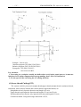
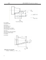
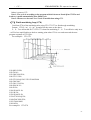
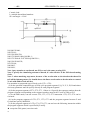
Chapter 5 System installation and connection......................................................................................................... 85
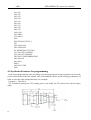
5.1 system installation and connection..............................................................................................................85
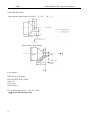
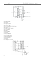
5.2 system installation dimension......................................................................................................................85
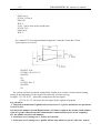
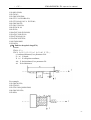
5.3 system rear view.......................................................................................................................................... 86
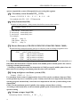
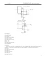
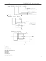
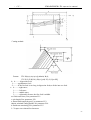
5.4 interface connection graph...........................................................................................................................86
Chapter 6 System’s daily maintenance and repair...................................................................................................99
6.1 System’s maintain........................................................................................................................................99
6.2 Ordinary trouble...........................................................................................................................................99
Chapter 7 Appendix............................................................................................................................................... 100
- -CNC -
SZGH-CNC2000TDb/TDc operation manual
Chapter 1 Preface
This CNC control system is one middle class flush type CNC control system, aiming specially
at lathe and grinding machine.
Based on modern computer technology, system move control core & PLC program running
technology, and stable unique real time control engine subsystem PTAI, this system ensures the
stabilization of operation. The use of high performance, low power consumption industrial grade
ARM microprocessor as core of hardware, large scale FPGA integrate circuit, multiple layer (4,6)
printed circuit, 32MB flash memory, 8 inch real color LCD which provides friendly man-machine
dialogue interface makes this system work to its best.
Note for “caution”:
1、“caution”reminds operator must be caution in the relative operation,otherwise the operation
will fail or some action can not be effected.
2 、 “special caution”reminds operator must be special caution in the relative operation ,
otherwise it may break down the machine or give rise to accident.
Special hint:
This system has function to backup parameters. After debugging machine, it can backup all
parameters of machine & system and PLC documents to computer. It is convenient not only for
mass debugging, but also for machine recovery to normal after changing system.
Note :
When use this system for the first time, please read carefully all the details of each
chapter so as to make it work more efficiently.
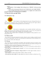
Chapter 2 System Technical Features
2.1 System constructions
32 bits high performance, low power consumption industrial grade ARM microprocessor.
64MB memory.
32Mb user store room.
640x480 8 inch real colour LCD displayer.
Touch screen main and sub panel.
High anti-jamming switch power.
USB movable U disc copy interface.
RS232 interface.
Spindle servo speed control/spindle frequency convertion speed control.
Manual pulse generator.
1
- -CNC-
SZGH-2000TDb/TDc operation manual
2.2 System technical parameter
controllable axes:X、Z、C/Y、A、B five axes.
linkage axes:Arc 2-3 axes, liner 2-5 axes.
pulse equivalent:X、Z、C/Y、A、B axes:0.001mm.
max speed:X、Z、C/Y、A、B:60000mm/min.
cutting speed:1-10000mm/min.
min input unit:0.001mm.
program size range:± 99999.999.
99 tools management.
controllable liner vertical type or revolving disc type tool changer.
program code:ISO-840 international standard.
program coordinate system definition:ISO-841.
chassis protection complies with regulation of IP43.
2.3 System function
2.3.1 Auto-diagnosis function
All around diagnosis of CPU, storer, LCD, I/O interface, parameter status, coordinates,
machining program etc. shall execute when the system starts or resets. In operation, it makes real
time diagnosis of power, spindle, limit and all I/O interface.
2.3.2 Compensation function
automatic backlash compensation.
tool radius automatic compensation.
tool radius automatic offset and sharp angle transition.
leading screw pitch error automatic compensation.
2.3.3 Abundant instruction system
scaling up/down instruction.
mirror machining instruction.
Multiple tool offset instruction.
program cycle, jump, call and different program ending.
multiple positioning instruction:starting point,setting fixed point,etc.
Linear, circular, spiral line interpolation instruction.
program management instructions: program cycle, call, transfer and different program ending
method, etc.
6 workpeices coordinates system .
2.3.4 Chinese/English menu, full screen edition
Easy operation, convenient viewing.
2.3.5 Abundant debugging functions
it can point out clearly what errors of operation are and guide to correct them.
2.3.6 Program changing between CNC system and IBM/PC series compatible computer
it can conduct CAD/CAM/CAPP auxiliary programming by using Pc series compatible
computer's abundant software resources , then transfer the CNC program into the system to
machining through(USB movable U disc copy port、RS232 port).Likewise it also can transfer
the program from system to PC through communication port.
2
- -CNC -
SZGH-CNC2000TDb/TDc operation manual
2.4 System operation condition
2.4.1 Power supplying
AC 220V(+10%/-15%), Frequency 50Hz±2%. power:≤ 100W.
Note:it must use isolation transformer to supply power,first input:380V
2.4.2 Climate condition
Operation condition:temperature 0~45℃,relative moisture 40-80%.
storage & transportation condition:temperature -40~55℃,relative moisture <93%(40℃).
atmosphere pressure:86-106kpa.
2.4.3 operation environment
No excessive flour dust, no acid, no alkali gas and explosive gas, no strong electromagnetic
interference.
Chapter 3 Operation explanation
When using the NC system, just master the parameter of system, edit program, manual
operation, auto operation. Then you can operate easily. There are some details to instruct
hereinafter.
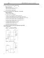
3.1Operation panel
This system is composed of the main panel and sub panel. The main panel is used for setting
parameter and editing program, the sub panel is used for setting tool and processing operation
3.2 Keyboard instruction
3.2.1 Rate increase
(1) Rapid override(G)
There are six gears in rapid override form 5% to 100%, by adjusting the key of rapid override is for
the following instruction: G00,G26,G28,G611,G613, rapid feed fixed cycle, rapid manual feed.
(2) Feed override(F)
There are sixteen gears in feed override from 0% to 150%, by adjusting the key of feed override is
for the following instruction:G01,G02,G03, the feed override of the fixed cycle and manual run
effectively.
(3) Spindle override(S)
There are sixteen gears in spindle override from 5% to 150%, by adjusting the key of spindle
override is for the speed of the first spindle.
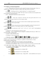
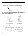
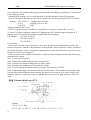
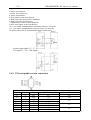
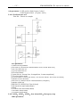
3.2.2 Panel layout and switch
Intervention switch introduction:
3
- -CNC-
SZGH-2000TDb/TDc operation manual
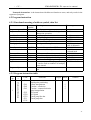
Switch
Functions
Emergency stop Driver and motor stop immediately, turns off the spindle,
coolant, waits for the rise of button, and initializes values
Intervention switch:
When program runs or in manual state, it can make a realtime adjustment
of feed speed;
Spindle percentage switch:
In the process of spindle running, adjusts the speed accordingly.
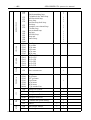
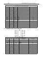
buttons:
Keyboards
Letter key
Number
key
Functions
AB C S E F G H I J K L M N O P Q R S TU V W X Y Z 1 23 4 5 6 7 89 . - : for program
instructions, parameters’ edition; number keys are used for inputting data and
selecting sub-menu.
“↑、↓、→、←、Del、PgUp、PgDn”for programming, direction keys can be used
for selecting menu.
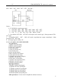
Edit key
Function
Key
“Esc” returning to upper level or stop a operation
“Enter” selecting sub-menu and changing a newline
“Del” delete program
“program”entering program edition
“parameter” entering parameter setting
“diagnsos” entering diagnosis I/o function
“manual” entering manual status
“handwheel” for starting or stopping handwheel function
“Tool” for confirming current tool ‘s position in machine tool coordinates system.
“Redeem” for amending tool change errors
“Auto” entering automatic status
“ M D I ” entering MDI function
“
“
”selecting auto-coordinates/diagram machining
” for coordinates mode or diagram mode speedy simulating
“
”for manual increment or constant work
“
Control
Key
“
” coolant on/off
“
”for the shift between electric tool carrier and gang tool carrier
“
speed.
4
”spindle cw, ccw rotation
” for the shift between hand-driven continuous high speed and low
- -CNC -
SZGH-CNC2000TDb/TDc operation manual
“
” all axes return to datum point
“
” for spindle chuck on/off
“
“
Control
Key
” for lubrication on/off
” for thumbstall on/off
“
”handwheel gear selection
“
” adjusting spindle speed
“
”adjusting feed speed
“
”adjusting G00 speed
Feed key
+C +A–C –A+ B-B
For X、Y/C、Z 、A 、B axes direction
feed
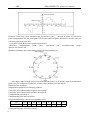
3.3 Manual Operation
The system adjusts one-level menu operation, intuitive, convenient, shortcut, prompt
comprehensive information.
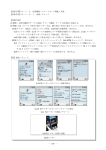
Whole system adopts multi-leveled menu full screen operation, user-friendly interface,
providing comprehensive information. It enters into main interface when electrified:
Powering the system is to enter the interface(Following shown)
5
- -CNC-
SZGH-2000TDb/TDc operation manual
3.3.1 The key of manual operation
(1) “F”: Taking mm/min as the unit to set the manual feed speed, the input range is from 1 to
30000mm/min. And the input method according to data input method in parameter.
(2) “
”: Switching cycle from “manual continuous” to “manual increment”
(3)“S”: Set the speed of the first spindle. The range is from 0 to 99999, the max depends on the
No.36 parameter in speed parameter.
(4)“I”: Modify the increment in manual increment
(5)“
” : Press once to increase or decrease 10% feed speed when the No.1 axis
parameter is 0, the range is from 0% to 150%,16 gears totally.
(6) “
”: Press once to increase or decrease G00 or manual rapid override 20%.The
range is from 5% to 100%,16 gears totally.
(7)“
”: Press once to increase or decrease the spindle override 10% when the No.2
parameter in axis parameter is 0. The range is form 5% to 150%,16 gears totally.
(8)“
”: To switch cycle “0.001” “0.01” “0.1”or “0.1” “0.01” “0.001” in the handwheel
function.
(9)“Diagnosis”: Enter the diagnosis of input or output.
(10)“Setup”:To set a value(G54-G59) in workpiece coordinate(G54-G59);Use “MDI” to set
G54-G59 in lathe coordinate(G53).
(11)“Auto”: Select automatic mode.
(12)“Manual”: Select manual mode.
(13)Spindle controlled: “
”Controlling spindle on
clockwise, counterclockwise, stop, correspond to instructions M03,M04,M05. When No.56
parameter in the axis parameter is “8”then press “spindle on counterclockwise” means
counterclockwise inching turning.
(14)“Cooling”: Coolant on or off correspond to instructions M08,M09.
(15)“Chuck”: Chuck tightens or loose correspond to instructions M10,M11.
(16)“Manual speed controlled”: Press “1” “2” “3” “4” “5” “6” “7” “8” “9” to set feed override
“F30” “F60” “F120” “F250” “F500” “F1000” “F1500” “F2000” “F2500” “F3000”.
(17) “Tailstock”: Tailstock tighten or loose correspond to instructions M79, M78.
1) manual main axle condition:
6
Press
the principal axis veer,display M03.
Press
the principal axis reverse,display M04。
Press
the principal axis stop,display M05。At this condition,users can press
- -CNC -
SZGH-CNC2000TDb/TDc operation manual
the key to turn off or turn on.
Press
M03 turn on point for while.
Press
the coolant to turn on or turn off.
Press
SP chuck to turn on or turn off.
Press
in choosing the position cutting tool.
Press
thumb stall to turn on or turn off.
2) Adjust the feed speed: The feed speed percentage can be controlled by the wave band switch or
the key
,the percentage increases or decreases 10%.The scope is 0 -150%,16 grades in all.
3) Control the principal axis speed: The main axle speed percentage can be controlled by the
wave band switch or the key
,the percentage increases or decreases 10%.The scope is 0
-150%,16 grades in all.
4) presses "stops": Stops the manual operation.
5) presses "F", there’s a dialog box used to alter the manual feed speed.That is convenient for
cutting by single axis.
6) presses "S",alter the principle axis’s revolving speed.
7) presses "T", choosing the position cutting tool.
(18) “Switch manual continuous or increment”: Press
it displays I=XXXX.XXX when it is manual increment.
to manual continuous or increment,
(19) “Back to datum point”: Press
and X or Z, the X or Z axis goes back to the datum
point automatically; Press “0”X axis firstly and then Z axis; Press “Esc” to cancel the construction.
The speed controlled by No.31 No.33 parameter in speed parameter, the direction is determined by
No.28 parameter in axis parameter.
(20) “Tool carrier controlled”: Press
to change next tool automatically if it is gang tool
carrier; After changing next tool it will be stop if it is electric tool carrier; Which tool has changed is
going to be redeem. Press “T” and number to change tool directly
(21) “Coordinates feed”: Press “↑ ↓ ← →”correspond to feed A axis and Z axis’s positive or
negative direction.
7
- -CNC-
(22) “Switch speed”: Press
SZGH-2000TDb/TDc operation manual
to switch the speed to system speed which is changed by
No.1 No.2 parameter in speed parameter when it is in coordinate feed, loosen it that will be the
previous speed. If set the speed higher than the speed in parameter, it will be the set speed to feed.
(23) “Switch coordinates’ display”: Press “PgUp” or “PgDn” to switch the display which
correspond to “relative” “absolute” “machine”.
(24) “Partno clear”: Press Del and Enter.
(25) User-defined “K1”: Turn on/off Y24
(26) User-defined “K2”: Turn on/off Y25
(27) User-defined “K3”: Turn on/off Y26
(28) “Incremental coordinate”: Press “Setup” to fix or set 0 after select “relative” coordinate.
PS: Lathe coordinate clear: Press “E” in parameter and then press “Enter”.
3.3.2 Manual continuous
Continuous operation is to press the time as the basis, Press to feed, up tp stop feeding. Making
sure the axis and using “↑ ↓ ← →” to feed, the speed of feed is determined by display on the
interface(F) times the rate.
When continuous starting, press “
” to switch the speed to No.1 No.2 parameter value in
speed parameter. If set the speed higher than the speed in parameter, the feed speed will be No.1 No.2
parameter in speed parameter times rapid override.
In order to facilitate the user single axis cutting in the manual function, setting the manual speed
in manual status. Press “F” and input the speed.
When the hard limit point beyond positive and negative feed running axis two direction at, stop
the feed and prompt to feed reverse direction.(the same as hereinafter)
The manual maximum speed is limited by No.3 parameter in speed parameter, when setting the
speed is higher than the value of parameter, then will be the No.3 parameter.
When No.38 other parameter is 8, “
” is change into a switch, press once to turn on (no
more to always press), press again to turn off.
3.3.3 Manual increment
This operation is to set the value of increment as the basis, press “↑ ↓ ← →” once to run a value of
increment. It will prompts “I=0010.000” in manual increment represent for the value of increment is
10mm, press “I” to revise and Enter.
The speed is the speed on display(F) times the rate.
3.3.4 Back to lathe’s datum point (reference point)
There are two ways to back to datum point in this system, not only the switch for datum point, but
also can set floating point, the methods as follows:
Switch for datum point:
Back to datum point operation is to feed every axis to lathe’s datum point position in turn. When the
parameter of feeding axis which back to datum point is 0, the axis of coordinate detects the datum
point and return to the pulsing signal of “Zero”, the data of lathe’s coordinate will be 0 automatically.
8
- -CNC -
SZGH-CNC2000TDb/TDc operation manual
Switch on the power supply of the system, release alarm and the button of emergency after the CNC
is power off, the need to back to datum point to set lathe’s coordinate correctly.
Instruction:
1. The system requires for backing to the datum point every time when it is power on, the
requirement can be set by No.26 parameter in axis parameter, it can be prompt or force;
2. The way and type of detecting signal can be set by No.27 parameter in axis parameter, so detect the
switch of datum point is effective, also detect the Z pulsing signal of electrical motor after detecting
the switch of datum point (precision higher), detect forward or reverse for Z pulsing signal of
electrical motor.
3. The direction for backing to datum point can be set by No.28 parameter in axis parameter, D2 D4
correspond to X Z axis, 0 is forward, 1 is reverse.
4. The sequence of X Z back to datum point can be set by No.28 parameter in axis parameter, X is
first when D8 is 0, Z is first when D8 is 1.
5. The type of the switch for datum point can be set by No.29 parameter in axis parameter, D0 D2
correspond to X Z axis,0 is always on, 1 is always off.
6. The maximum length of detecting Z pulse of electrical motor can be set by No.30 No.31 parameter
in axis parameter, the value must less than the pulse of electrical motor run a cycle.
7. The shifting distance after backing to datum point can be set by No.32 No.33 parameter in axis
parameter, rapid move coordinate to the value of parameter after backing to datum point.
No switch for datum point: To set floating point to make sure, turn on corresponding function of
floating point by No.23 parameter in axis parameter, setting No.24 No.25 parameter to make sure X
axis’ and Z axis’ floating point, the datum point of lathe.
The steps to set floating point as follows:
1. Setting the No.23 parameter in axis parameter to set the axis which is starting up floating point. For
example: Turn X axis on is “00001000”. (Z axis is “00100000” turn both of them on is 00101000.)
2. Moving X axis to designated position so that set floating point.
3. Press “Parameter”, “Axis parameter” and select No.24 parameter, “Enter”, popup a dialog box of
X axis’ floating point coordinate. Import the value of setting lathe coordinate.
If it is 0, the lathe coordinate of X axis now is the datum point of X axis. The lathe backs to this
position every time when backing to the datum point.
If it is 15, the current lathe coordinate of X axis is 15.000, the distance to lathe’s datum point is
15mm.
The method to set floating point of Z axis is the same as the above to set X axis.
Operation for backing to the datum point:
At the manual condition, press “
”and select X Y Z A B axis to back to the datum point in
dialog box. Set the No.28 parameter in axis parameter to “1” to make Z axis bake to the datum point
first. At the absolute and relative coordinate condition, the cycle will turn to green in front when
backing to the datum point successfully, defeat otherwise.
If stop in the process, press “Stop” or “Reset” to stop backing to the datum point.
Pay attention: Every time to power up the system must back to the datum point to make sure
the accuracy of lathe process. The system power off unusually or in an accident, it must back to
the datum point, otherwise could cause trouble.
9
- -CNC-
SZGH-2000TDb/TDc operation manual
3.3.5 Handwheel(Manual pulse generator)
Two types: hand held and panel, No.1 parameter in other parameter to set.
Panel:Press “handwheel” and “Z” or “X” to select an axis, “
” to adjust the gear.
Hand held: Press “handwheel” and operate the switch of axis selection to select an axis, operate the
axis and switch of handwheel override to adjust the gear.
Instruction
The handwheel is mainly used for “Tool”, the speed and the handwheel feed of one measure is
related to rotate the handwheel fast or low. The speed is not too fast best when the system cooperate
with stepping motor.
Handwheel’s pulse generator speed to be lower than 200r/min(The handwheel to 100 pulse a cycle),
the Handwheel’s acceleration is controlled by No.17 parameter in speed parameter(the bigger the
faster). The maximum speed is controlled by No.20(X axis) No.21(Z axis).
Handwheel is of no effect in auto-coordinates diagram machining, it only works in working
coordinates.
3.3.6 Tool
Because no tool is the same when using multiple tools machining so need to identify them previous
the value of the redemption, that is to carry out redeeming. Tooling is actually move the tool to the
workpiece surface at this point, the point's actual measurement of values import directly into the
system the system calculates the deviation and save to the corresponding tool offset register
automatically.
Press “Tool” ,then choose “X” or “Z” and “Enter” to select axis. There are two methods:
Plan A(suggest)
(1) Clamped workpiece, select appropriate spindle speed and feed speed, start spindle.
(2)Select the tool to “Tool”, for example: T0202
(3)Using manual continuous to cut a bit of cylinder or bore on workpiece.
(4)Z axis exits(X axis can’t move), stop spindle.
(5) Measure the diameter of workpiece(cylinder or bore).
(6)Press “Tool”, then “X”, “Enter” and import the above value of measurement into dialog box, press
“Enter” to confirm.
(7)Use the same method to cut end surface of workpiece.
(8)Measure the end surface of workpiece and spindle chuck (Z=0) into the distance.
(9)Press “Tool”, then “Z”, “Enter” and import the above value of measurement into dialog box, press
“Enter” to confirm.
The second tool is already done(T02).Repeat (1) ——(9) to make others tools get done.
Plan B
(1) Clamped workpiece, select appropriate spindle speed and feed speed, start spindle.
(2) Select the tool to “Tool”, for example: T0202
(3) Using manual continuous to cut a bit of cylinder or bore on workpiece.
(4)Press “Tool”, the system will appear a dialog box.
(5)X axis and Z axis both exit, stop spindle.
(6) Measure the diameter of workpiece(cylinder or bore).
10
- -CNC -
SZGH-CNC2000TDb/TDc operation manual
(7)Press “X” and import the above value of measurement into dialog box, press “Enter” to confirm.
(8) Use the same method to cut end surface of workpiece. Stop feeding.
(9) Press “Tool”, the system will appear a dialog box.
(10) X axis and Z axis both exit, stop spindle.
(11) Measure the end surface of workpiece and spindle chuck (Z=0) into the distance.
(12)Press “Z” and import the above value of measurement into dialog box, press “Enter” to confirm.
The second tool is already done(T02).Repeat (1) ——(12) to make others tools get done.
The difference between two methods:
Method (recommend)
Method B
(1) Make sure the “Tool” axis couldn’t exit. (1) The axis can exit.
(2) The tool must touch workpiece.
(2The tool mustn’t touch workpiece.
(3) Use “Z” axis’ direction to “Tool”
(3)Use “X” axis’ direction to “Tool”.
In the above process, the import value’s and lathe coordinate value’s difference will be saved to the
corresponding cutter compensation by system automatically. So the inaccuracy of setting tools can
be modified correctly by corresponding cutter.
System to each tool independently of each other, each has its own coordinate system, so each tool
can “Tool” anytime and the tool is destroyed in the process is only the tool.
Instruction
1. When a group of tool to be used for two or more parts processing requires the working
coordinate to achieve the overall shifting tool group. So, make sure the value of workpiece
coordinate before setting tools. Methods of operation are as follows:
(1)Select a tool.
(2) Press “F8” to select corresponding coordinates (54-59).
(3) Using manual continuous to cut a bit of cylinder or bore on workpiece.
(4) Z axis exits(X axis can’t move), stop spindle.
(5) Measure the diameter of workpiece(cylinder or bore).
(6) Press “F7”, “X” and “Enter”, import the value of measure, press “Enter”.
(7) Use the same method to cut end surface of workpiece.
(8) Measure the end surface of workpiece and spindle chuck (Z=0) into the distance.
(9) Press “F7”, “Z” and import the value of measure, press “Enter”.
The import value’s and Tool coordinate value’s difference will be saved to the corresponding
parameter by system automatically, corresponding workpiece coordinate is been set now. It’s done
after finishing setting tools as the above. It’s done that the code in first line to execute selection of the
corresponding coordinate.
2. Just setting one of the tools after the lathe crashing or loss of step, every tool is okay.
The method: In the G53 status, switch “F6” into “F7” as the above operations.
3.4 Auto operation
Auto refers to processing the editing program of workpiece. This system can start at arbitrary point,
and also can start at arbitrary line or with arbitrary tool. Starting arbitrary line or with arbitrary tool
must use absolute coordinate to edit the program. Auto operation can’t move the manual coordinate.
Running program selection: In the program interface, press “↑ ↓” to move the cursor to a program
which is going to be carry out, press “F7” to select the program to carry out automatically.
11
- -CNC-
SZGH-2000TDb/TDc operation manual
Switch the display of coordinate: Press “F1-F3” to switch the display which correspond to
“relative” “absolute” “machine”.
3.4.1 Automatical process
“Single or continuous”: Press “
” to switch cycle.
“Continuous”: The program continue to execute every program segment(program line) to end or the
instruction of stop to stop.
“Single ”: The program just execute one program line and end, wait another operation or press
“Run” again to execute one next program line.
“Coordinate or figure”: Press “
” to switch cycle.
“Automatically coordinate”: The axis of coordinate will display with value.
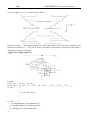
“Automatically figure”: The axis of coordinate will display with a figure. There are two kinds of
figure, horizontal lathe and slant-bed lathe, No.3 parameter in tool parameter to control.
“
”: The program is speedy simulate, the axis of coordinate can’t move.
3.4.2 Processing at arbitrary program line or with arbitrary tool
A. Import the line to run
At the automatical process condition, press “—” to popup a dialog box, import a number of line,
press “Enter” to confirm, the line will be the line to run.
Pay attention:1. The line is the actual line in the program, not the “N” stand for the line. The
system process to the line you import with a speed which is set by No.5 parameter in speed
parameter(G01/G02/G03), then process the program normally.
2. The line of default is the line of suspend the program last time, to facilitate user’s
operations.
3. At the interface of coordinate to use “N” to search line and press “Reset” to back to the
beginning of program.
B. Mark the line to run
The system has a function to run at the marking line. At automatical process condition, press “N” to
popup a dialog box to import the marking line, press “Enter” to confirm. Press “Run” to process
program at the line you import(mark).
Pay attention:
The line is not the actual line, is the “N” stand for the line. The system process to the line you
import with a speed which is set by No.5 parameter in speed parameter(G01/G02/G03), then
process the program normally.
C. Some tool to run
The system has a function to run at some tool. At automatical process condition, press “G” and the
number of tool to run(only the number of tool, not the number of compensation; Like: 0304, just
import “03”), press “Enter” to confirm. Press “Run” to process program at the tool you import.
Pay attention: The system process to the line you import with a speed which is set by No.5
parameter in speed parameter(G01/G02/G03), then process the program normally.
3.4.3 Start program
12
- -CNC -
SZGH-CNC2000TDb/TDc operation manual
Press “Auto” to switch to automatical mode to process program, two methods as follows.
(1) Press “Run”
(2) Switch on the Run of external signal.
3.4.4 Stop processing program
Five methods as follows to stop:
(1) The instruction of program M00 M01 M02 M30 M20.
(2) Press “
” to run a current line and stop.
(3) Intervention switch in the middle or right.
(4) Switch on the Halt of external signal.
(5) Press “Reset” to stop all the actions of program.(Like spindle, tools and others)
3.4.5 Real-time control in automatical process
(1) Intervention switch: For suspend feed coordinate and stop spindle. Left, middle, right 3 gears
totally.
Left: Feeding coordinate and spindle is not limited.
Middle: Stop feeding, spindle is not limited.
Right: Stop feeding and spindle.
Stop here means suspend, turn left the switch to continue process; Press “Reset” to exit automatical
process and stop processing, the program line is going to back to the first of the processing program.
At the manual mode condition, spindle is not limited by intervention switch, only by the button.
(2)“
”:Press once to increase or decrease 10% feed speed when the No.1 axis parameter
is 0, the range is from 0% to 150%,16 gears totally; When the No.1 axis parameter is 1, external band
switch takes in control, Adjust the speed of process arbitrarily in the process according to the
different situation.
(3) “
”: Press once to increase or decrease G00 or manual rapid override 20%.The range
is from 5% to 100%,16 gears totally. Adjust the rapid override arbitrarily according to the different
situation.
(4) “
”: Press once to increase or decrease the spindle override 10% when the No.2
parameter in axis parameter is 0. The range is form 5% to 150%,16 gears totally. When the No.1 axis
parameter is 1, external band switch takes in control, Adjust the speed of spindle arbitrarily in the
process according to the different situation.
(5) Stop in the process: At the continuous mode in process condition, press “
” to stop running
after executing a current program line, wait for operating.
(6) Suspend in the process: Turn the intervention switch right or middle and switch on external stop
signal of Halt, the processing program will stop; Press “Reset” to exit automatical process mode and
the program line is going to back to the first of the processing program.
13
- -CNC-
SZGH-2000TDb/TDc operation manual
(7) Keep feeding: When the process is suspending, press “Manual” to keep feeding automatically,
also can adjust the coordinate, press “Auto” and “Run” to run to the point of suspend automatically to
end.
(8) Exit process: Press “Reset” when processing, suspending or keep feeding.
3.4.6 The operation mode of MDI
At the manual or automatical coordinate conditions, press “MDI” to get into the processing mode of
MDI. Processing a program line that you import in “MDI”, press “Esc” to give up and exit when
importing, press “Run” to carry out the program line that you import.
3.4.7 The operation mode of Handwheel
Press “Handwheel” at automatical mode, the program of turn handwheel is processing
automatically, the speed is related to the speed of “F”, feed override and turn handwheel fast or slow.
This mode is for trying to process in running program usually.
Pay attention: The acceleration, deceleration and maximum speed of running handwheel are
controlled by No.17 No.18 No.19 No.20 No.21 No.43 parameter in speed parameter and No.23
parameter in processing parameter, use the acquiescent acceleration, deceleration and the
speed of G00 when the parameter is set to be invalid.
3.4.8 The function of DNC
The storage space of user is 32Mbit in this system, use DNC to process when the processing
program is greater than 32M or the remainder storage space. Switch on RS232 or USB to realize the
function of DNC in this system.
A. Instruction for RS232-DNC
1. Use the dedicated communication line to connect the computer and the system to set the
corresponding communication interface and speed by the system.
2. Use the dedicated communication software of this system by computer to set the
corresponding communication interface and speed. Press “Send CNC program file”, select the
program file to process linked, enter the status of sending program file.
3. To enter the interface of program file in NC system, press "L" to enter the status of linked
process, now the upper right corner of the display interface is "RS232--DNC", press “Run” to
running carry out linked process in the automatical status.
4. Turn “Intervention switch” to middle or right to stop the running system in the process of
linked process, press “Stop” or “Reset” to exit the status of linked process.
Pay attention: 1. The baud rate is related to operational environment when using serial
port to send files.
2. The communication cable can’t more than 10 meters length.
3. Only the dedicated communication software of this system can send program in
user’s computer. To set the sending speed of PC as the NC, defeat otherwise.
B. Instruction of USB-DNC
USB-DNC is realized by U-disk, switch on U-disk and system, select program to execute in
U-disk.
Press “F6” to open U-disk in program interface, select corresponding program to press “F7”
to execute program, press “Auto” to get into automatical mode and press “Run” to process the
14
- -CNC -
SZGH-CNC2000TDb/TDc operation manual
program.
Pay attention: 1. Don’t unplug U-disk in the process of USB-DNC, defeat processing
otherwise.
2. Back to the system program interface from U-disk interface after finish USB-DNC.
3. After selecting the program, it is best to press “P” to compile once to make sure the
program is right before executing program of USB-DNC.
3.5 Operate safety, prompt alarm
3.5.1 Emergency stop
Press “
” when emergency accidents happening, the system will stop all the actions of
lathe and shows “Emergency stop” on the interface. Wait for the button up. M67 imports effective
signal when No.29 parameter in other parameter to be set effectively.
Press “
” in the process or running lathe, system coordinate and lathe’s position may
change, make sure the system coordinate again before processing, it is best to carry out operation of
backing to the datum point to make coordinate same as the lathe’s position.
The button can be external which is controlled by No.27 parameter in other parameter to set it
always open or close.
3.5.2 Reset system
Press “Reset” to stop current operation in anytime when the system is running, especially stop all
the actions of lathe(spindle, tools and so on) in automatical or manual mode, but the coordinate won’t
lose, so needn’t to back to the datum point.
3.5.3 Alarm
The screen shows error information and twinkles when the lathe has alarm, the program is stop
running, the coordinate stop moving, check the reason for alarm and clear troubles to run again. The
signal M67 is effective when No.29 parameter in other parameter is “1”.
(1) X and Z axis are limited positive forcedly : X or Z axis is in the positive position which is
limited forcedly.
(2) X and Z axis are limited negative forcedly: X or Z axis is in the negative position which is
limited forcedly.
(3) Spindle and inverter (frequency changer) alarm: The alarm signal of lathe’s inverter is
effective. (ALM1)
(4) No.0 alarm: The alarm signal of lathe’s spindle is effective.(ALM2)
(5) X and Z axis’ driver alarm: The alarm signal of servo drivers is effective. (ALM). Press “B” to
15
- -CNC-
SZGH-2000TDb/TDc operation manual
import INTH signal to reset the servo drivers in diagnosis mode.
(6) No.5 alarm for door switch: The alarm signal of M12(door switch) is effective.
(7) +5V is under voltage: Supply voltage is low, +5V of the system is low.
(8) Emergency stop: Press the button of emergency stop.
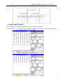
3.6 Parameters operation
At any status conditions, press “parameter” to enter the status to set the parameter. Parameter in this
system includes “processing parameter” “speed parameter” “axis parameter” “tool parameter” “other
parameter” “coordinate” “password”, 7 kinds totally.
In
main
menu,
pressing“Parameter”function
key,
it
enters
para
setting
status,including“User”,“Speed”,“Axis”,“Tool” ,“Other” ,“Coor” ,“Passwd",seven function. Choose
pressing “F1、F2、F3、F4、F5、F6、F7、F8” choose Except for special note, all data are using mm.
Except for special note, all data are using mm.
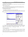
Press “F1-F7” correspondingly to enter corresponding interface after enter the parameter
interface, press “↑ ↓” to select the number of parameter and press “Enter” to popup a dialog box
to import data and press “Enter” again to fix parameter successfully.
Instructions for parameter as follows:
3.6.1 User parameter(Processing parameter)
Parameter List:
1,Cycle G71/G72 default feed thickness(10um) [X axis radius]
Cycle G71 X axis feed thickness; Cycle G72 Z axis feed thickness;
2,Cycle G71/G72 default backward distance(10um) [X axis radius]
Cycle G71 X axis backward thickness; Cycle G72 Z axis backward thickness.
3,G71G72G173 instruction [1 mean Yes,0 mean No]
16
- -CNC -
SZGH-CNC2000TDb/TDc operation manual
“1”mean G71/G72/G73 instruction finish machining.
4,G71/G72/G73 default X remain(10um)
5,G71/G72/G73 default Z remain(10um)
6,G73 cutting times
7,G73 X rough thickness(10um) [X axis radius]
8,G73 Z rough thickness(10um)
9,G74/G75 default feed thickness(10um) [X axis radius]
10,G74/G75 default backward distance(10um) [X axis radius]
11,G76 finish turn times
12,G76 quit length(1/10 lead)
13,G76 thread tooth angle(degree) [0~180°]
14,G76 minimal cutting depth(10um) [X axis radius]
15,G76 finish turn remaining(10um)
16,X program mode [1 mean Radius,0 mean Diameter]
17,Running program need Sp run [1 mean Yes,0 mean No]
18,Set M20 the time of auto-running [Negative number mean immensity loop]
19,Set part count
20,G92 quit length(1/10 lead)
21,G01/G02/G03 line delay(ms)[>100]
22,G00 line delay(ms)[>100]
23,Handwheel acceleration[50-100]
24,G76 Q [8 mean thick forward number]
200,system screen protect times [>=2minutes]
201,G92/G76 delay time(ms)[>100]
202,system inner parameter(no set)
Explanation of User Parameter(processing parameter)
1,Cycle G71/G72 default feed thickness(10um)
It is set for every default infeed (radius) in X-axis direction when it isn’t be set in G71
code;unit:0.01mm.
It is set for every default infeed (radius) in Z-axis direction when it isn’t be set in G72
code;unit:0.01mm.
2,Cycle G71/G72 default backward distance(10um)
It is set for every default backward (radius) in X-axis direction when it isn’t be set in G71
code;unit:0.01mm.
It is set for every default backward (radius) in Z-axis direction when it isn’t be set in G72
code;unit:0.01mm.
3,G71G72G173 instruction
It is for whether smoothing automatically when use G71/G72/G73 code.
When set to 0,mean no; when set to 1,mean yes.
4,G71/G72/G73 default X remain(10um)
It is set for every default remain of smoothing(diameter) in X-axis direction when it isn’t be
set in G71/G72/G73 code;unit:0.01mm.
5,G71/G72/G73 default Z remain(10um)
It is set for every default remain of smoothing(diameter) in Z-axis direction when it isn’t be set
17
- -CNC-
SZGH-2000TDb/TDc operation manual
in G71/G72/G73 code;unit:0.01mm.
6,G73 cutting times
It is for default cycle times when it isn’t be set in G73 code.
7,G73 X rough thickness(10um)
It is for default rough thickness of X axis when it isn’t be set in G73 code.
8,G73 Z rough thickness(10um)
It is for default rough thickness of Z axis when it isn’t be set in G73 code.
9,G74/G75 default feed thickness(10um)
It is for every default infeed in Z-axis direction when it isn’t be set in G74 code;unit:0.01mm.
It is for every default infeed (radius) in X-axis direction when it isn’t be set in G75
code;unit:0.01mm.
10,G74/G75 default backward distance(10um)
It is for every default retract in Z-axis direction when it isn’t be set in G74 code;unit:0.01mm.
It is for every default retract (radius) in X-axis direction when it isn’t be set in G75
code;unit:0.01mm.
11,G76 finish turn times
It is for default cycle times when it isn’t be set in G76 code.(times:1-99)
12,G76 quit length(1/10 lead)
It is for default length of retract chamfer when it isn’t be set in G76 code.the length is 1/10 of
thread lead.
13,G76 thread tooth angle(degree)
It is for default angle of thread tooth when it isn’t be set in G76 code.unit:degree.
14,G76 minimal cutting depth(10um) [X axis radius]
It is for set minimal cutting depth (radius) of G76.Unit:0.1mm
15,G76 finish turn remaining(10um)
It is for default remaining of finish turn when it isn’t be set in G76 code.unit:0.01mm.
16,X program mode [1 mean Radius,0 mean Diameter]
There are two programming modes ,when it set as 1 that means radius programming mode,when
set as 0 means that diameter programming mode
17,Running program need Sp run [1 mean Yes,0 mean No]
It is for interlock between run program and run spindle,when set as 1means that running program
with running spindle;when set as 0 means that running program without check spindle running.
18,Set M20 the times of auto-running [Negative number mean immensity loop]
It is for times of run M20 code in the program,negative number mean run countless times.
19,Set part count
It is for display and set the time of run M20,it is also workpiece number.
20,G92 quit length(1/10 lead)
It is for set default length of quit and retract,the length=thread lead * 0.1.
21,G01/G02/G03 line delay(ms)[>100]
It is for set delay time between G01/G02/G03,it is for solve the over-cutting in the corner.
22,G00 line delay(ms)[>100]
It is for set delay time after run G00 ,it is effective that more than 100ms.
23,Handwheel acceleration[50-100]
It is for set the constant of handwheel smoothly acc/dec-eleration. the smaller it is,the faster the
18
- -CNC -
SZGH-CNC2000TDb/TDc operation manual
acc/dec-eleration is,but much vibration.
24,G76 Q [8 mean thick forward number]
It is for set the define of Q in G76,set as “8”,it is the times of feeding in roughing.
200,system screen protect times [>=2minutes]
201,G92/G76 delay time(ms)[>100]
It is for set delay time before check Z pulse when process screw.
3.6.2 Speed parameter
1,X-axis's G00 speed(mm/min)
2,Z-axis's G00 speed(mm/min)
3,Manual maximum feed speed(mm/min)
4,Auto Maximum feed speed(mm/min)
5,G01/G02/G03 default speed(mm/min)
6,Null run speed(mm/min)
7,Feed axis`s manual speed(mm/min)
8,Spindle`s manual speed(rpm)
9,Beginning feed speed(mm/min)
10,Jump speed at continuous track(mm/min)
11,Limit G1G2G3 axis speed [1 mean Yes,0 mean No]
12,X G1G2G3 max speed(mm/min)
13,Z G1G2G3 max speed(mm/min)
14,X acceleration [1~99999]
15,Z acceleration [1~99999]
16,Auto run acceleration [1-500]
17,Handwheel acceleration [500--30000]
18,Run program Handwheel acceleration [>500]
19,Run program Handwheel G00 speed(mm/min) [>10]
20,Handwheel X limit speed(mm/min)
21,Handwheel Z limit speed(mm/min)
22,Make thread Z acceleration [Servo motor is 0]
23,Make thread X acceleration [Servo motor is 0]
24,Servo motor screw thread X axis Back speed
25,Step motor screw thread X axis Back rise speed
26,Step motor screw thread X axis Back Max speed
27,acceleration type [0 mean line,8 mean curve]
28,curve ini acceleration [>=10]
29,curve acceleration [>=10]
30,curve max acceleration [>=500]
31,X go home rampit speed(mm/min)
32,X go home reverse speed(mm/min)
33,Z go home rampit speed(mm/min)
34,Z go home reverse speed(mm/min)
35,G96 spindle min speed(rpm)
36,Spindle first max speed(rpm)
19
- -CNC-
SZGH-2000TDb/TDc operation manual
37,Spindle second max speed(rpm)
38,Spindle third max speed(rpm)
39,Spindle forth max speed(rpm)
40,Second Spindle max speed(rpm)
41,G02/G03reverse compensation mode(0 mean A; 8 mean B)
42,mode B reverse compensation speed(mm/min)
42-1,mode B reverse compensation Beginning feed speed(mm/min)
42-2,mode B reverse compensation acceleration(mm/min/s)
43,Handwheel stop speed(mm/min)[>100]
58,Forcedly limit drop speed critical(mm/min)
Introduction:
1,X-axis's G00 speed(mm/min) 2,Z-axis's G00 speed(mm/min)
The max is 30000(unit:mm/min)
Note:the value must take machine configuration into consideration ,set wrong is very dangerous.
3,Manual maximum feed speed(mm/min)
It is limitation of max feed speed in manual ,Unit:mm/min.(reference speed=G00 speed*0.5 )
4,Auto Maximum feed speed(mm/min)
It is the max of feed speed in auto ,Unit:mm/min.the speed could faster than G00 speed.
5,G01/G02/G03 default speed(mm/min)
It is the default speed of G01/G02/G03 when it isn’t set in auto-running.Max:5000(unit:mm/min)
6,Null run speed(mm/min)
It is speed of null run. (press “simulate” is dry run) Max:30000. (unit:mm/min)
7,Feed axis`s manual speed(mm/min)
It is the speed of feeding axis in Manual.Range: <max feeding speed (unit:mm/min)
Note:in Manual,press “F” ,refresh the parameters automatically.
8,Spindle`s manual speed(rpm)
It is speed of spindle in manual.Unit:rpm.
Note:in Manual,press “S” ,refresh the parameters automatically.
9,Beginning feed speed(mm/min)
It is beginning speed of feeding axis when acc/dec-eleration.when it is smaller than acceleration/
deceleration ,accelerate/decelerate start from the beginning feed speed.when it is bigger than
acceleration/deceleration,the speed reached directly.
Note:it is related with machine configuration,in general,stepper system is less than 100,servo
system is less than 500.
10,Jump speed at continuous track(mm/min)
It is for increase the continuous when running multiaxial track-interpolation.
Example:when it is 300,the speed of X axis(multiaxial track-interpolation)up from F800 to
F1600,800(=1600-800)>300,so the process is up from F800 to F1100,and then F1600.
11,Limit G1/G2/G3 axis speed [1 mean Yes,0 mean No]
It is for whether limit the max speed of each axis when G1/G2/G3 interpolating.
12,X G1G2G3 max speed(mm/min)
It is for the Max running speed of X-axis when set G1/G2/G3 interpolation.
13,Z G1G2G3 max speed(mm/min)
20
- -CNC -
SZGH-CNC2000TDb/TDc operation manual
It is for the Max running speed of Z-axis when set G1/G2/G3 interpolation.
14,X acceleration [1~99999]
It is time constant of X-axis acc/dec-eleration,the bigger it is ,the faster the ace/dec-eleration is.
Note:This value depends on the machine structure,the heavier the load is ,the smaller the value
is.With stepper system,the value should less than 15000.
15,Z acceleration [1~99999]
It is time constant of Z-axis acc/dec-eleration,the bigger it is ,the faster the ace/dec-eleration is.
Note:This value depends on the machine structure,the heavier the load is ,the smaller the value
is.With stepper system,the value should less than 15000.
16,Auto run acceleration [1-500]
It is for set constant of acc/dec-eleration in auto.the range is from 1-500.It is mainly for
distinguish Auto and Manual,only the difference is too much,set it is effective.
17,Handwheel acceleration [500--32000]
It is for set constant of acc/dec-eleration of Handwheel.the range is from 500-32000.
18,Run program Handwheel acceleration [>500]
It is for set constant of acc/dec-eleration of Handwheel when running program.the range is from
500-32000.when the value is less than 500,it is invalid.
19,Run program Handwheel G00 speed(mm/min) [>10]
It is the G00 speed when triggered by Handwheel in testing machine.it is invalid when <10.
20,Handwheel X limit speed(mm/min)
It is for limit the handwheel max speed of X-axis when use handwheel in manual.
Note:it is valid when >100,otherwise invalid.
21,Handwheel Z limit speed(mm/min)
It is for limit the handwheel max speed of Z-axis when use handwheel in manual.
Note:it is valid when >100,otherwise invalid.
22,Make thread Z acceleration [Servo motor is 0]
It is time constant of Z-axis ace/dec-eleration,the range is from 300 to 90000.
Note:with stepper system,the smaller it is ,the safer is.when <300,invalid.For ensure efficiency,set 0.
23,Make thread X acceleration [Servo motor is 0]
It is time constant of Z-axis ace/dec-eleration,the range is from 300 to 90000.
Note:with stepper system,the smaller,the safer.when <300,invalid.For ensure efficiency,set 0.
24,Servo motor screw thread X axis Back speed
It is the speed rate of X axis in servo system when back in processing screw thread.Unit:0.1times.
25,Step motor screw thread X axis Back rise speed
It is the start speed of X axis in step system when back in processing screw thread.Unit:mm/min.
Note: for safe,it should less than 100mm/min.
26,Step motor screw thread X axis Back Max speed
It is the Max speed of X axis in step system when back in processing screw thread.Unit:mm/min.
Note: for safe,it should less than 100mm/min.
27,acceleration type [0 mean line,8 mean curve]
It is for set type of ace/dec-eleration.set 0 means line type.set 8 means curve type.
Note:In normal condition,set line type in step system;set curve type in servo system.
28,curve ini acceleration [>=10]
It is initial ace/dec-eleration constant when set curve type.It is valid when >=10.
21
- -CNC-
SZGH-2000TDb/TDc operation manual
29,curve acceleration [>=10]
It is second ace/dec-eleration constant when set curve type.It is valid when >=10.
30,curve max acceleration [>=500]
It is Max ace/dec-eleration constant when set curve type.
It is valid when >=500,otherwise the ace/dec-eleration constant is with line type of each axis.
31,X go home rampit speed(mm/min)
It is speed of X-axis when go home in forward direction.Unit:mm/min.the range is less than the
G00 speed of X-axis.
32,X go home reverse speed(mm/min)
It is speed of X-axis when go home in reverse direction.Unit:mm/min.the range is 20-500.
Note:it is for ensure accuracy.the smaller it is ,the higher the accuracy is.when set well,don’t
change it forever.
33,Z go home rampit speed(mm/min)
It is speed of Z-axis when go home in forward direction.Unit:mm/min.the range is less than the
G00 speed of Z-axis.
34,Z go home reverse speed(mm/min)
It is speed of Z-axis when go home in reverse direction.Unit:mm/min.the range is 20-500.
Note:it is for ensure accuracy.the smaller it is ,the higher the accuracy is.when set well,don’t
change it forever.
35,G96 spindle min speed(rpm)
It is the min speed of spindle when run G96 code.
36,Spindle first max speed(rpm)
It is the first max speed of spindle,it is also the speed when voltage is 10V.unit:r/min
37,Spindle second max speed(rpm)
It is the second max speed of spindle,it is also the speed when voltage is 10V.unit:r/min
38,Spindle third max speed(rpm)
It is the third max speed of spindle,it is also the speed when voltage is 10V.unit:r/min
39,Spindle forth max speed(rpm)
It is the forth max speed of spindle,it is also the speed when voltage is 10V.unit:r/min
40,Second Spindle max speed(rpm)
It is the max speed of the second spindle,it is also the speed when voltage is 10V.unit:r/min
41,reverse compensation mode(0 mean A; 8 mean B)
It is reverse compensation mode of arc gap.
0 means A mode.(A mode is the bigger it is ,the faster the speed is.the speed should not be bigger
than 1000mm/min,the speed also is related with the value of reverse gap compensation.)
8 means B mode.(B mode is the speed depends on the related parameters. )
42,mode B reverse compensation speed(mm/min)
It is the speed of reverse compensation in B mode.unit:mm/min.
42-1,mode B reverse compensation Beginning feed speed(mm/min)
It is beginning speed of reverse compensation in B mode.it is valid when it >10.unit:mm/min.
42-2,mode B reverse compensation acceleration(mm/min/s)
It is the constant of reverse compensation acceleration It is valid when it >=10.unit:mm/min
43,Handwheel stop speed(mm/min)[>100]
It is the speed when handwheel stop.the bigger it is ,the shorter the stop time is.
22
- -CNC -
SZGH-CNC2000TDb/TDc operation manual
58,Forcedly limit drop speed critical(mm/min)
It is starting drop speed when it is force limit.when servo system, it is 1.
3.6.3 Axis parameter
1,Feed axis band switch [1 mean Yes,0 mean No]
2,Spindle band switch [1 mean Yes,0 mean No]
3,X-axis`s negative scope(mm)
4,X-axis`s positive scope(mm)
5,Z-axis`s negative scope(mm)
6,Z-axis`s positive scope(mm)
7,Spindle stop time(10ms)
8,Spindle stop long signal [0 mean No,1 mean Yes]
9,Check SP encode : [1 mean Yes,0 mean No]
10,SP encode pulse
11,Soft limit invalid [D2X;D3Y;D4Z;D5A;0 invalid,0 valid]
12,X-axis`s reverse compensation(um)
13,Z-axis`s reverse compensation(um)
14,X-axis's direction signal [1 mean normal,0 mean reverse]
15,Z-axis's direction signal [1 mean normal,0 mean reverse]
16,Close feed electron gear [1 mean Yes,0 mean No]
17,X-axis's electron gear numerator(1-999999)
18,X-axis's electron gear denominator(1-999999)
19,Z-axis's electron gear numerator(1-999999)
20,Z-axis's electron gear denominator(1-999999)
21,XZ positive limit [0 open,1 close]
22,XZ negative limit [0 open,1 close]
23,float zero bit parameter [D3X;D4Y;D5Z;D6A;0 machine Zero;1 float Zero]
24,X coordinate float zero set
25,Z coordinate float zero set
26,Feed axis home [1 mean No use, 0 mean clew, 8 compulsion , 9 must compulsion]
27,Feed axis home mode [0 reverse check,1 reverse No check ,2 No reverse check,3 No reverse No
check]
28,Home reverse direction [D2X;D3C(Y);D4Z;D5A;D6B;D8Zpriority]
29,Home NC switch bit set [D0X;D1C(Y);D2Z;D3A;D4B;D7:Manual/Auto cut
automatically ;1Close;0Open]
30,X check zero max length(100um)
31,Z check zero max length(100um)
32,X Home offset(10um)
33,Z Home offset(10um)
50,Have Spindle class control : [1 mean open,0 mean close]
51,Spindle class speed(1/100rpm)
52,Spindle class direction : [0 mean M03,1 mean M04]
53,Spindle class stop time(10ms)
54,Spindle class time(10ms)
55,Spindle stop time(10ms)
80,XZ axis coordinate plan[D2Zwordpiece,D3Xwordpiece,D4Ztool,D5Xtool,
D6Zcircumrotate,D7Xcircumrotate]
404,SP motor direction(0 reverse,1 normal)
405,SP-axis's electron gear(0 Yes,1 No)
406,SP-axis's electron low gear numerator(1-999999)
407,SP-axis's electron low gear denominator(1-999999)
408,SP-axis's electron high gear numerator(1-999999)
23
- -CNC-
SZGH-2000TDb/TDc operation manual
409,SP-axis's electron high gear denominator(1-999999)
410,Interpolation tap SP name[91 X,92 Y/C,93 Z,94 A,95 B]
411,Interpolation tap mode[2 follow encode;3 interpolation to SP]
412,SP tooth number(<P413)
413,Encode number(>P412)
Introduction:
1,Feed axis band switch [1 mean Yes,0 mean No]
It is for operation way of alter feeding axis’s rate.1 mean selection external band switch(it is the
band switch in additional panel.) to alter.0 mean use Feed rate+/-.
2,Spindle band switch [1 mean Yes,0 mean No]
It is for operation way of alter spindle axis’s rate.1 mean selection external band switch(it is the
band switch in additional panel.) to alter.0 mean use SP rate+/-.
3,X-axis`s negative scope(mm)
It is the coordinate value of X-axis soft limit in max scope of negative direction.
4,X-axis`s positive scope(mm)
It is the coordinate value of X-axis soft limit in max scope of positive direction.
5,Z-axis`s negative scope(mm)
It is the coordinate value of Z-axis soft limit in max scope of negative direction.
6,Z-axis`s positive scope(mm)
It is the coordinate value of Z-axis soft limit in max scope of negative direction.
7,Spindle stop time(10ms)
It is the braking time of spindle,the shorter it is,the faster the brake is.
8,Spindle stop long signal [0 mean No,1 mean Yes]
When it is 1,the signal of spindle is long signal,when it is 0,it is short signal.
9,Check SP encoder : [1 mean Yes,0 mean No]
It is for whether the system check the signal of spindle encoder,also the spindle’s position feedback.
When 1 mean check ,o mean no check.the spindle gear ration must be 1:1 with spindle encoder.
10,SP encode pulse
It is the feedback pulses of each rev of spindle encoder.It is lines (of SP-encoder) * 4.
11,Soft limit invalid [D2X;D3Y;D4Z;D5A;0 invalid,0 valid]
It is invalid bit parameter of soft limit.every axis is set alone.D2:X;D3:Y(C);D4:Z,D5:A;D6:B.
Example:the soft limit of X-axis is valid,the bit parameter is 00000100.
12,X-axis`s reverse compensation(um)
It is the value of reverse compensation(radius),when X-axis is running in negative direction.when
X-axis run in negative direction,system compensate with the value.
13,Z-axis`s reverse compensation(um)
It is the value of reverse compensation(radius),when Z-axis is running in negative direction.when
Z-axis run in negative direction,system compensate with the value.
14,X-axis's direction signal [1 mean normal,0 mean reverse]
It is for change the direction of X-axis.when it is 0,the direction of code is opposite to the direction
of moving.when it is1,the direction is same.
15,Z-axis's direction signal [1 mean normal,0 mean reverse]
It is for change the direction of X-axis.when it is 0,the direction of code is opposite to the direction
of moving.when it is1,the direction is same.
16,Close feed electron gear [1 mean Yes,0 mean No]
It is for whether close the electron gear of feeding axis.1 mean close,0 mean no close.
17,X-axis's electron gear numerator(1-999999)
It is the numerator of X-axis’s electron gear
18,X-axis's electron gear denominator(1-999999)
It is the denominator of X-axis’s electron gear
19,Z-axis's electron gear numerator(1-999999)
It is the numerator of Z-axis’s electron gear
24
- -CNC -
SZGH-CNC2000TDb/TDc operation manual
20,Z-axis's electron gear denominator(1-999999)
It is the denominator of Z-axis’s electron gear
21,XZ positive limit [0 open,1 close]
It is for type of limit switch in positive direction.0 means the switch is open,1 means it is close.
22,XZ negative limit [0 open,1 close]
It is for type of limit switch in negative direction.0 means the switch is open,1 means it is close.
23,float zero bit parameter [D3X;D4(C)Y;D5Z;D6A;0 machine Zero;1 float Zero]
It is for whether the float zero function is valid,every axis is set alone.it is bit parameter. D3:X;
D4:C(Y); D5:Z; D6:A; D7:B.1 means the axis is float zero point,0 mean machine zero point.
Example:X set float zero point,the bit parameter is 00001000.
24,X coordinate float zero set
It is the coordinate value of X-axis float zero point.
25,Z coordinate float zero set
It is the coordinate value of Z-axis float zero point.
26,Feed axis home [1 mean No use, 0 mean clew, 8 compulsion , 9 must compulsion]
It is request that feeding axis go home.there is four kinds way of go home as follow:
1 means no request.when boot every time,no prompt and no limitation;
0 means prompt,when boot every time,there will be a prompted screen;
8 means enforcement,when boot every time,there will a prompted screen,and then,if the system
don’t go home,it will note “feed axis don’t go home” ,and don’t run the program;
9 means much enforcement,when boot every time,there will a prompted screen,and then,if the
system don’t go home,it will note “feed axis don’t go home” ,and feed axis don’t move.
27,Feed axis home mode [0 reverse check,1 reverse No check ,2 No reverse check,3 No reverse No
check]
It is mode that check the switch and Z pulse of motor’s encoder when feeding axis go home:
When it is 0,go home after hit the switch,move in reverse direction until check the switch is
disengaged,and then check the Z pulse of encoder.
When it is 1,go home after hit the switch,move in reverse direction until check the switch is
disengaged.
When it is 2,go home after hit the switch,move forward until check the switch is disengaged,and
then check the Z pulse of encoder.
When it is the rest,go home after hit the switch,move forward until check the switch is disengaged.
28,Home reverse direction [D2X;D3C(Y);D4Z;D5A;D6B;D8Zpriority]
It is for the direction and priority that feeding axis go home.It is bit parameter,each axis is set
alone.D2:X ;D3:C(Y) ;D4:Z ;D5:A ;D6:B ;D8:XZ priority,1 mean negative direction,0 mean
positive,D8 control the priority that X&Z-axis go home.1 means Z-axis first,0 means X-axis first.
Example:when set X-axis go home in negative direction,the bit parameter is 100000100.
29,Home NC switch bit set [D0X;D1C(Y);D2Z;D3A;D4B;D7:Manual/Auto cut automatically ;1:
Close ; 0: Open]
It is the mode of home switch,set alone,it is bit parameter. D0:X; D1C(Y); D2Z; D3A; D4B;
D7:Manual/Auto cut automatically,when after program in auto enter manual condition
automatically ;1: NC(normal close); 0: open.
Example:If X&Z axis are NC switch,the bit parameter is 000000101.
30,X check zero max length(unit:100um)
It is the length that check zero pulse of encoder when go home and after disengaged switch.
Note:the value must be less than the length of one rev,otherwise,go wrong home.
31,Z check zero max length(unit:100um)
It is the length that check zero pulse of encoder when go home and after disengaged switch.
Note:the value must be less than the length of one rev,otherwise,go wrong home.
32,X Home offset(unit:10um,-9999~+9999)
It is offset that X-axis move in G00 speed when X-axis go home ,after check zero pulse.unit:0.01m.
33,Z Home offset(unit:10um,-9999~+9999)
It is offset that Z-axis move in G00 speed when X-axis go home ,after check zero pulse.unit:0.01m.
25
- -CNC-
SZGH-2000TDb/TDc operation manual
50,Have Spindle class control : [1 mean open,0 mean close]
It is whether the spindle is booting when change gears.1 mean spindle is open,0 mean close.
51,Spindle class speed(1/100rpm)
It is the speed that the spindle boot when the spindle change gears.
52,Spindle class direction : [0 mean M03,1 mean M04]
It is the direction that the spindle boot when SP change gears,1 means reverse,0 means forward.
53,Spindle class stop time(unit:10ms)
It is the time that the spindle stop (M05) when SP change gears.
54,Spindle class time(unit:10ms)
It is the time that the spindle run in low class.unit:10ms
55,Spindle stop time(unit:10ms)
It is the delay time between cancel M03/M04 and boot M05.unit:10ms.
80,XZ axis coordinate plan[D2Zworkpiece,D3Xworkpiece,D4Ztool,D5Xtool,D6 Z
circumrotate ,D7Xcircumrotate]
It is bit parameter,D2:Z axis in workpiece coordinate system;D3:X axis in workpiece coordinate
system;D4 is Z axis in machine coordinate system;D5 is X axis in machine coordinate system.D6 is
Z axis whether is rotation axis;D7 is X axis whether is rotation axis.1 means valid/yes;0 means
invalid/no.
404,SP motor direction(0 reverse,1 normal)
It is the direction of spindle motor,o means reverse,1 mean normal.
405,SP-axis's electron gear(0 Yes,1 No)
It is for whether the spindle use electron gear.
406,SP-axis's electron low gear numerator(1-999999)
It is the numerator of SP-axis’s electron low gear in low gear.
407,SP-axis's electron low gear denominator(1-999999)
It is the denominator of SP-axis’s electron low gear in low gear.
408,SP-axis's electron high gear numerator(1-999999)
It is the numerator of SP-axis’s electron low gear in high gear.
409,SP-axis's electron high gear denominator(1-999999)
It is the denominator of SP-axis’s electron low gear in high gear.
410,Interpolation tap SP name[91 X,92 Y/C,93 Z,94 A,95 B]
It is the axis that be use for spindle when interpolation tap.
411,Interpolation tap mode[2 follow encode;3 interpolation to SP]
It is control mode of interpolation tap.
412,SP tooth number(<P413)
It is tooth number of spindle.it <=P413.
413,Encode number(>P412)
It is tooth number of SP-encoder,it >=P412.
Note:the tooth number of spindle must be not more than the tooth number of SP-encoder,when less,it
need to install our company’s adapter plate.
3.6.4 Tool parameter
1,Active tool function : [1 mean Yes,0 mean No]
It is for whether activate electric turret(tool).
Note:when the machine is with linear turret without electric turret,the parameter be set as 0,and also
use Txxxx code to control tools and radius/tool compensation.
2,Active tool number of electric turret.
It is the total number of electric turret.
Example:when lath machine have four-electric turret and four-linear turret,in “Redeem” screen,
press F7 “Set”,input tool total count is 8,and the parameter is 4,so T1-T4 means electric
26
- -CNC -
SZGH-CNC2000TDb/TDc operation manual
turret,T5-T8 means linear turret.
3,Lather type
It is type of lath machine’s structure.0:turret in front of horizontal lathe; 1:turret behind of
horizontal lathe;2:turret in front of vertical lathe;3:turret behind of vertical lathe.
4,Tool positive rotate max-time(s)
It is the max-time that the turret is changing tool automatically.when over the time,the system stop
ATC and alarm.
5,Delay time after tool positive rotate(ms)
It is delay time that check the tool signal(Tok) after the turret rotated
6,Delay time after tool stop(ms)
It is the delay time that is between the turret forward rotate is okay and stop,also is between cancel
forward rotate signal(+T) and output reverse rotate signal(-T).unit:ms.
7,Tighten time of tool reverse rotate(ms)
It is the time tighten tool in reverse rotate, also is the time that output the siganl of “-T”.
Note:the bigger the value is,the hotter the motor is.
9,Have total signal TOK(1 mean have)
It is for whether check the signal of “TOK”,1 means check it,o means not.
10,C Tool radius compensation's establish(0 mean A,1 mean B)
11,C Tool radius compensation's cancel(0 mean A,1 mean B)
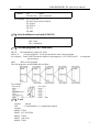
20,Active tool mode :[1 mean normal,0 mean coding tool]
3.6.5 Other parameter
1,Set sub-panel type : [1 hand hold,0 panel]
It is the type of handwheel,1 means hand held type,0 means handwheel in panel(C panel).
Note:when the parameter is 1(P1=1),CN11(handwheel port) couldn’t be used to alter axis,so P1,P2
only set as 0.A/X/Y(C)/Z to select axis,X1/X10/X100/OFF to select grade.
2,lather outside chuck : [1 extroversion,0 diffidence]
3,use control switch : [1 Yes, 0 No]
It is for whether the tamper switch is valid.1 means valid,0 mean invalid.
4,Have auto lubricate(0 Yes/ 1 No)
It is for whether the auto lubricate is valid.1 means valid,0 mean invalid.
Note:auto lubricate is decided by working time.
5,Auto lubricate time(0.01s)
It is the time of auto lubricate,also time that M32 is valid.unit:0.01s.
6,Auto lubricate stop time(s)
It is the interval that lubricate every time,also the interval that twice M32 is valid.unit:s.
7,Door switch checking M12(0 no,1 yes)
It is for whether the system check the signal of safe-door.0 means there isn’t safe-door,1 mean
there is safe-door and check it.
Note:for the check of safe-door,it is realized by M12.
When set valid and M12 is also valid,in Manual,system could work,but in Auto,it not.
8,Door switch(Model :0 open,1 close)
It is type of safe-door.0 means normal open type,1 means NC(normal close).
9,bit parameter
27
- -CNC-
SZGH-2000TDb/TDc operation manual
D0:Null;
D1:“1”Start CNC system clear part Number.;
D2:“1”Automatic space before letter when edit program;
D3:Null;
D4:Null;
D5:“1”Do not stopping SP and cooling when pressing “Restet”;
D6:“1”G00 XZ’speed by oneself;
D7:“1”Tool’redeem by oneself;
D8:“1”Save SP chuck(M10/M11) state when power off;
D9:Tool redeem input Mode1 or Mode2;
D10:“1” Program edit automatic compositor Line;
D11:“1”First SP +10V output from second output port;
D12:“1”Shield skip function (“/”is invalidation);
D13:“1”Shield go home function;
D14:“1”Shield “run” key;
D15:“1” Tool redeem display relative,“0”absolute;
10,Auto count part : [1 mean Yes,0 mean No]
It is for whether count workpiece automatically,1 means count,0 meas not.
11,Program edit number increase
12,Inner parameter
13,Does lock for Spindle & chuck(0 mean no)
It is for whether interlock between running spindle and chuck.1 means interlock,0 means no.
14,Is available keys of lubricate&coolant as running(0 mean no)
It is for whether the coolant is valid in Auto.when P14=0,it is invalid.1 means valid.
15,Chuck clamp M10/loose M11 checking(1 mean need)
16,Finial forward M79/backward M78 checking(1 mean need)
17,servo ALM (0 open,1 close)
It is the type that system check ALM of servo drive(Pin12 in CN5),1 mean normal close,0 open.
18,SP ALM1 (0 open,1 close)
It is the type that system check ALM1 of Spindle(Pin5 in CN3),1 mean normal close,0 open.
19,Tool ALM2 (0 open,1 close)
It is the type that system check ALM2 of tool(Pin2 in CN10),1 mean normal close,0 open.
20,Chuck control signal(0 single,1 doubleM10/M71)
It is for set the chuck control signal is single or double,M10/M71 are the two signal.
When set as 0,only use M10 to control chuck.when M10 is valid,tighten tool,otherwise invalid.
When set as 1,use M10&M71 to control chuck.when M10 is valid and M71 is invalid,tighten
tool,otherwise when M10 is invalid and M71 is valid,loose tool.(M10 output M10,M11 output M71)
Check whether it is in place,P40 in Axis parameter,1 means check,0 means no. When set as
check,M10 is in place,and the system also check whether M40 is valid automatically,when M40 is
valid,do next step.Loose tool M11,tool is in place,and the system also check whether M12 is valid
automatically,when M12 is valid,do next step.
21,finial control signal(0 single,1 doubleM79/M73)
22,Outside chuck control(0 no,1 yes)
It is for whether use external switch(button) to control tighten/loose tool,it is reciprocating
28
- -CNC -
SZGH-CNC2000TDb/TDc operation manual
signal,one time is valid,tighten tool,next time is invalid,loose tool.when set 0 means without
external switch,when with external switch,the signal is M16.
23,Outside finial control(0 no,1 yes)
24,M10M11 short signal time(s)
It is for stay time that output M10,M71 is short signal.0 means them is long signal.unit:s.
25,M79M78 short signal time(s)
26,Emerge Stop(0 open,1 close)
It is the type of emerge stop1-switch in operation panel.for safe,advice set 1--Normal close.
27,Emerge Stop2(0 open,1 close)
It is the type of emerge stop2-switch in handwheel or external switch.(Pin5 in CN11).for
safe,advice set 1--Normal close.
28,Run status output M69 STOP output M65(0 invalid,1 valid)
29,Alarm status output M67(0 invalid,1 valid)
30,Set language(1 表中文, 0 mean English)
31,Is enable I/O PLC program
32,Is enable High speed I/O PLC program
33,HY make run signal :[1 mean Yes,0 mean No]
34,HA make stop signal :[1 mean Yes,0 mean No]
35,soft-limit without home as manual :[1 Yes,0 No]
36,Set system time :[year-month-day-hour-minute]
37,Velocity of RS232
[0=7200;1=9600;2=14400;3=19200;4=38400;5=57600;6=115200]
Note: the bigger the value is,the unstabler it is.
The bits of both ends must keep same.
38,Lock Manual rampit func key :[8 Yes]
39,Special parameter
40,Special parameter
41,Bake current parameter
It is defined to ex-factory value set.it is used for bake current parameter after test system well.
42,Resume original parameter
601,Make current to Step Motor Parameter
602,Make current to Servo Motor Parameter
3.6.6 Work coordinate system parameter
1,X of work coordinates G54(mm)
2,C(Y) of work coordinates G54(mm)
3,Z of work coordinates G54(mm)
4,A of work coordinates G54(mm)
6,X of work coordinates G55(mm)
7,C(Y) of work coordinates G55(mm)
8,Z of work coordinates G55(mm)
9,A of work coordinates G55(mm)
11,X of work coordinates G56(mm)
12,C(Y) of work coordinates G56(mm)
13,Z of work coordinates G56(mm)
14,A of work coordinates G56(mm)
29
- -CNC-
SZGH-2000TDb/TDc operation manual
16,X of work coordinates G57(mm)
17,C(Y) of work coordinates G57(mm)
18,Z of work coordinates G57(mm)
19,A of work coordinates G57(mm)
21,X of work coordinates G58(mm)
22,C(Y) of work coordinates G58(mm)
23,Z of work coordinates G58(mm)
24,A of work coordinates G58(mm)
26,X of work coordinates G59(mm)
27,C(Y) of work coordinates G59(mm)
28,Z of work coordinates G59(mm)
29,A of work coordinates G59(mm)
3.6.7 Password
password setting include:
1,Is enable CNC Co.’s password ?
2,Is enable Machine Co.’s password ?
3,Is enable User’s password ?
4,Modify CNC Co.’s password:
5,Modify Machine Co.’s password:
6,Modify User’s password:
7,curry word time: (days)
8.Version of Software.
3.7 Set parameter of tool redeem
Press “Redeem” to enter interface of redeem in any interface, including “Radius compensation”
“Redeem” “Clear all value” “Clear current value” “Measure tool” “Posit tool” “Set”, total 7
functions, correspond to “F1-F7” to enter corresponding interface,press “Esc” to back the primary
menu interface.
3.7.1 Radius compensation
Press “F1” enter radius compensation interface in redeem interface. The parameter is used to set
30
- -CNC -
SZGH-CNC2000TDb/TDc operation manual
adopt corner radius of the tool.
Setting method: Press “↑ ↓” to make cursor move to the corresponding tool and press “Enter” to
popup a dialog box, import corresponding tool radius, press “Enter” at last.
Press “F3” or “F4” to make all initial or current tools to be 0.
Pay attention: Redeem number couldn’t correspond to tool, every tool could use any redeem
number, radius compensation correspond to redeem number, so the number of redeem is the
same as the number of radius compensation.
3.7.2 Length of redeem
Press “F2” to enter length of redeem interface. The parameter is used to modify the length which is
adopt or reset the length.
Method of modifying the length:
Press “↑ ↓” to make cursor move to the corresponding tool number and press “Enter” to popup a
dialog box, import the modifying axis into the dialog box and import the modifying value(import
0.05 to plus 0.05, import -0.05 to reduce 0.05), press “Enter” to confirm. The system calculates
current value of redeem after finishing setting.
Method of reset the length:
Make lathe move to a position so that measure corresponding tool coordinate, press “↑ ↓” to make
cursor move to corresponding tool number and press “F5” to popup a dialog box, import the reset
axis into dialog box and import the value of measuring the workpiece of corresponding axis, press
“Enter” to confirm. The length compensation of corresponding axis has been reset. The system
automatical refresh current value of redeem after finishing setting.
Method of initializing the length compensation value of tool:
Press “F3” or “F4” to initialize all the length compensation or current length compensation.
3.7.3 Posit tool
Press “F6” to enter posit tool interface in redeem interface. The parameter is used to set the kind of
tool when adopting radius compensation of tool.
Method of setting: Press “↑ ↓” to make cursor move to corresponding tool number and press “Enter”
to popup a dialog box, import the code of corresponding tool kinds and press “Enter” to confirm.
Press “F1” to initialize all the kinds of tools to 0.
Introduction of posit tool
Only use the function of tool compensation offset when the tool is cycle to make a correct
processing program is very difficult. The function of tool compensation could compensate
automatically.
31
- -CNC-
SZGH-2000TDb/TDc operation manual
A. Posit tool
The nose of tool point(A) is non-existent actually as follow picture. Setting posit tool is easier
than setting actual center of tool (Hereinafter). Using posit tool to programme do not need to
consider the tool radius. The tool in the origin of the position relation as shown below.
Pay attention: For some lathes with electrical datum point, a standard point(like center nose
of tool) can be the starting point. The distance form the standard point to the radius center of
tool rest or posit tool can be the offset of tool.
When tool rest is at the beginning point.
Using the central nose of nose to programme
32
- -CNC -
SZGH-CNC2000TDb/TDc operation manual
Using the posit tool to programme
B. Direction of posit tool
From the central nose of tool to see the direction of posit tool is determined by the direction of
cutting tool, so must set before as the same time with the value of compensation. The direction of
posit tool can be selected by the 8 kinds of corresponding number as shown below.
The direction of posit tool of backward tool rest
The direction of posit tool of forward tool rest
Using No.0 posit tool or No.9 when the central nose of tool is coinciding with starting position. Set
the number of posit tool into tool parameter in every number of offset.
3.7.4 Set quantity of Tools
Press “F7” to popup a dialog box in the redeem interface to set and manage the total tools.
It is also the total tools of Electrical tool and Linear tool.
3.8 Set Parameter of screw compensation
Press “Parameter” button twice soon,and then enter screw compensation interface to set the
screw compensation.
33
- -CNC-
SZGH-2000TDb/TDc operation manual
Screw compensation interface
Screw compensation is used for automatical compensating the error of screw pitch, compensate
the influence from the error of screw pitch to the prevision of operating lathe. The system adopts
storage mode of screw compensation: Making the lathe’s datum point as the starting point when
debugging, measured the error curve of screw, studied out the correctional curve according to the
error curve, import the value of correctional curve into the correctional parameter and system is
going to compensate according to the parameter in automatical running.
Screw compensation is set and storage unit in axis , X Z axis is set separately, by pressing “F1”
“F2” “F3” “F4” “F5”to chose screw compensation of related axis; screw compensation interface of
each axis has tow areas(basic parameter and set the value of compensation), by pressing “→ ←”key
to move the cursor and choose.
Basic parameter:
Press “↑ ↓” to select current basic parameter to set in basic parameter, press “Enter” to popup a
dialog box to import the error compensation of every axis and import the basic information of screw
compensation.
Set the value of compensation:
In the area of setting compensation, it will shows the value of compensation and every axis’ error
compensation point of screw pitch. Press “↑ ↓ PgDn PgUp” to select current compensation point and
press “Enter” to popup a dialog box to import the value of compensation, import the value of current
compensation point.
Test program generation automatically
It is that automatically generate a program,which is go through the laser interferometer to check
the screw compensation.
Enter the screw compensation interface and set basic parameter, press “F6” (ChePro--checking
program) to popup a dialog box and then press “Enter” to generate corresponding checking program
of screw compensation.
The number of cmpensation point can be set optionally, Compensation parameters include:
34
- -CNC -
SZGH-CNC2000TDb/TDc operation manual
Compensation point NO.of reference point.
Com.point NO.of farest end in negative direction.
Com.point NO.of farest end in positive direction.
compensation percentage.
interval between compensation point(um).
Compensation value
compensation point
System automatically figures out each axis pitch error compensation point position according
to basic parameters. Each axis pitch error compensation point is distributed with equal interval;
users can input each point compensation value.
The interval of compenstion point is set on the each axis,
For example:
Example 1:Linear axis:when length of travel is -400mm ~ +800mm,interval of points
50mm,reference point compensation NO. 40,it can figure out that Com.point NO.of farest end in
negative direction is:
Machine negative travel/point interval +1=40-400/50+1=33.
Com.point NO.of farest end in positive direction is:
Machine positive travel/point interval +1=40+800/50=56.
Machine coordinate and compensation point NO.correspondence is:
output compensation value in 0 position
parameters set as follows:
compensation point NO.of reference point:40
Com.point NO.of farest end in negative direction:30
Com.point NO.of farest end in positive direction:56
Compensation percentage:1
Compensation point interval:50000
Compensation point and value contrast:
Corresponding compensation point and value:
The compensation value in corresponding compensation point:
33
No.
Value +2
34
35
36
37
38
39
40
41
42
43
44
45
46
47
48
49
56
+1
+1
-2
0
-1
0
-1
+2
+1
0
-1
-1
-2
0
+1
+2
+1
The contrasted chart of compensation points and value as follows:
35
- -CNC-
SZGH-2000TDb/TDc operation manual
Example 2:rotor axis: when movement per revolution is 360°, interval of points 45°,reference
point compensation NO. 60, Com.point NO.of farest end in negative direction is usually same as
reference point com.point NO.
Com.point NO.of farest end in positive direction is:
Reference
compensation
point
NO.+
movement
per
revolution/comp
point
interval=60+360/45=68.
Machine coordinate and compensation point NO.correspondence is:
note: input value in small circle. If the total amount from 61 to 68 doesn’t equal 0,accumulated
pitch error per revolution will deviate, so same value shall be put in 60 and 68.
Parameter sets as follows:
compensation point NO.of reference point:60
Com.point NO.of farest end in negative direction:60
Com.point NO.of farest end in positive direction:68
Compensation percentage:1
Compensation point interval:45000
Output compensation value at corresponding point:
NO.
VALUE
60
+1
61
-2
62
+1
Compensation point and value contrast:
36
63
+3
64
-1
65
-1
66
-3
67
+2
68
+1
- -CNC -
SZGH-CNC2000TDb/TDc operation manual
3.9 Input/output Diagnosis
Press “Diagnosis” to enter the diagnosis interface in parameter interface.
Press “F2” and “↑ ↓” to check the status of input and output, press “F4” to check alarm information.
System diagnosis interface(Input signal)
System diagnosis interface(output signal)
37
- -CNC-
SZGH-2000TDb/TDc operation manual
Checking interface of output signal
In the interface of output or input, No.0 or No.1 stands for status, 1 means effective, 0 means no
effect.
Alarm information interface
Press “F4(ALARM)”,the first line in this interface shows the number of spindle encoder, the
number of current and historical alarm information is record total 10, the superfluous part is clear
automatically, only shows 10 alarm information recently.
3.10 Program Edit operation
Press “Program” in any menu to enter into status of programming.
Program management adopts documents management mode,due to NAND FLASH,this system
can store 32MB program.user program can be protected by password. Edition is made by full screen
mode.
In main interface,press“program”to pop up interface of choosing program.
Center part of screen for program display,current program is showed by reverse display, move
PgUp 、 PgDn to choose program, and then press“Enter”to edit current program. Functional
keys“F1、F2、F3、F4、F5、F6、F7、F8” include:“new file/search” 、“copy” 、“rename” 、
“information”、“last grade”“USB disc”、“execute program”、“cancel”.
3.10.1 new file/search
when this button is pressed, it pops up the requirement to input the name of new/searched
documents,it can be number,letter(no difference if it is capital letter or small letter) or other
mixture of symbol(not include / \ : * ? “ < > | and ),no limitation on length。Input document name,
then press “enter” to confirm.if it exists in system,it will be found and reversely displayed,if not, it
will be newly build and reversely displayed. To build a new file.
38
- -CNC -
SZGH-CNC2000TDb/TDc operation manual
The edition mainly uses to edit,insert,modify,delete and so on. After selects the program name
and enter the entire screen edition system. The menu at the base of the screen includes (press “F1、
F2、F3、F4、F5、F6、F7”)"compile ", "first line ", "Teaching", "pose", “del line "," >> "(“del
block”“copy block”“array”“serch”“alter”“aalter”“<<”)," cancel",etc.
Users can operate at the area of line number at the left side of the screen.
The program name to edit and the line number to point were clue at the top of the screen.
1) pose the cursor: change the cursor’s position
Press “↑ ↓ ← →” to move the cursor to any position in program content.
Press “PgUp” to move the cursor to last page.
Press “PgDn” to move the cursor to next page.
Press "Enter",to the next line.
Press “pose”and key in line number can locate directly to the line which you key in.
Press “first line” locate directly to "the first line".
Press “endline” locate directly to the end line.
When the located program line surpasses the page,it will automatically change to the next page
and the located program line will be contained in the display .
2) insert: key in the insertion in front of the cursor,if they are letters,it will automatically
produces blank space.
3) delete:presses "Del"can delete the character at the back of the cursor.
4)shift KEY: presse twice key in the shift character.
5) delete line :press “RAPIT+delete line” to delete the line.
6)operate the block : Contains copy block and delete block.
7)compile:compile the source program (ISO code)to the computer code procedure.
show error when compile,or show “OK”.
When enters the automatic main function, this system automatically carries on concealed
compiling process .If there’s a mistake,the system clues on the error message.
"compile" includes " compile NC" and " compile MAC".
8) search: Uses to search the appointed character string.
9) replace: “alter”Uses to replace the appointed character string.
39
- -CNC-
SZGH-2000TDb/TDc operation manual
10) all replace:“aalter” Use to replace all appointed character string from the cursor to the
ending of the program
press “Emergency brake”can stop carrying on " search", " alter", "all alter".
11)exit: press "Esc" or F8 returns to the main interface and save the program automatically.
3.10.2 copy
it is reduplicating current program to another program. Choose this item to pop up dialogue
box,input new document name,if it exists,input is invalid, if not,this name will be the name
of newly copied document.
3.10.3 rename
for convenience of management, the original documents can be renamed. Choose this item to
pop up dialogue box,input new document name,if it exists,input is invalid, if not,this name
will be the name of original document.
3.10.4 delete
“Del”for deleting all content and name of current program.
3.10.5 infomation
This system provides users information column for each program, which is convenient for
users to amend and set.
Length of document(uneditable)
Last time of document amending(uneditable).
3.10.6 USBdisc
Press “F6” open or close U disk.
note:before pulling out U,it must return to directory of doc name. otherwise newly copied
data in U may lose.
3.10.7 Serial port transmission program
Besides U,can use RS232 port. In interface of choosing program,press R to receive program,
press T to send program:
Then can communicate the program according to the interface.The following chart shows:
Transmit the program file from PC to CNC:run CNC CO.’s special series communication
software on PC . Clicks the "transmits the CNC program file" button and select , clicks the "turns
on" button,now PC is waiting for transmiting; press "R" under the “program”interface,keys in the
program file name.The PC begins to transmit.
Transmit the program file from CNC to PC: presses the key "↑" "↓"to selet the program file
name under the interface of “program” ,then press "T", now the system is waiting for
transmitting;Run CNC CO.’s special series communication software in PC. Click the "receives the
CNC program file" button, key in the program file name in the dialog box, clicks on the "save"
button,now the system begins to transmit the program file.
3.10.8 editing
40
- -CNC -
SZGH-CNC2000TDb/TDc operation manual
Select “New file/search” to popup a dialog box to import the name of program, if the name is existent,
the quondam program is called up; If the name is in-existent, the system will build a new file.
The name of program can be number, letter or mix, the length is 100 bits.
The system doesn’t allow the namesake, build a new program or select a program and press “Enter”
to enter the editing interface.
3.10.9 Select the machining procedure
Select the machining procedure before the automatically machining. The operating procedure is:
Press "↑" "↓" to select the program and press “execute”(“F7”key).
41
- -CNC-
SZGH-2000TDb/TDc operation manual
Chapter4 Programming
CNC lathe is highly effective automatical equipment according to programmed program to
process workpiece. Programming refers to process of using cnc language to describe machining track
and actions based on the machining blueprint and technique requirement.
4.1 basic concepts
program segment: is a complete command line consisted of instruction segment and data
segment.
Program: is a congregation of program segment by machining logic structure in order to
complete the machining of workpiece.
Machine coordinate system: see fig Lathe top view.
Machine coordinate stipulates machine coordinate and direction, z axis parallels spindle,
direction away from spindle is positive. X axis is vertical to spindle, the opposite of knifepoint is
positive.
Lathe top view
SERVO MOTOR
CNC
CONTROLLER
SPINDLE
BOX
CHUCK
c
+Z
+X
TOOL
Absolute programming: it is confirmed coordinates data programming mode based on
established absolute coordinate system. X, Z、C/Y stand for it.
Relative programming (increment programming): is the distance and direction of operation
end point, compared with starting point. U, W,V stand for it.
Mixed programming: is the programming of one segment program by both absolute
programming and relative programming.
Diameter programming: all X axis coordinate are presented by diameter.
Starting point: the place where the tool begins to move when program starts.
Name of program: the name of machining program.
Mode instruction: the instruction which can remain the function in the program. It works both
in this program and program in the future.
In the same operation, there may be several mode instruction, such as M03 (spindle clockwise),
M04 (spindle counter clockwise), M05 (spindle stop). They are all Mode used to control spindle. The
mode of same kind are categorized into one mode group. At any time it must be one of them, and
there is only one of them. The original chosen mode instruction is called mode origin. In the above
mode group, M05 is such a mode origin.
Suspending mode (destroying mode): is the instruction which can turn mode instruction into
mode origin or destroy the mode. Such as M20 (program ending instruction), meaning the end of
operation and returning to original status.
42
- -CNC -
SZGH-CNC2000TDb/TDc operation manual
Non mode instruction: is the instruction which has no function to store, and only works in the
segment of program.
4.2 Program instruction
4.2.1 Functional meaning of address symbol, data list.
Functions
Meaning
Program segment No.
Preparation function
Address
symbol
N
G
Data range
Auxiliary function
Tool function
Spindle function
Spindle function
Cutting speed
M
T
S
SS
F
Coordinates character
Lead of screw thread
XU ZW
F(I)
Core coordinates
Arc radius
Delay time
Program entrance
Repeat times
IK
R
XUP
P
L
Program skip
/
00-99
Tool T0101-9999
0-65000
0-65000
1-30000mm/min,
0.001-9.999mm/n
The coordinates value of X Z axes
±99999.9999mm
F for metric, I for imperial
0.1-1000mm,
1-99teeth/inch
X Z axes coordinate increment value
±99999.9999mm
Arc radius value, tool radius value
0.001-99999.999mm
Delay time of designalated delay
0.001-65s
Entrance of calling program segment
0000-99999
Times of cycle or subprogram calling 1-65000
1-99
L can be used as numbers of multiply
screw thread
There is “/”befor N ,this line does not
run.
No of program segment
Content and mode of designalated
instruction operation
Auxiliary operation instruction
Tool changing instruction
The first spindle speed
The second spindle speed
Speed per minute, per rotation
00-99
4.2.2 Program instruction table
Gro
up
Natur
e
Code
Functions
G00
Main control functions
1
G01
G02
G03
G32
G332
G333
G31
G311
Rapid point positioning
Linear interpolation
Circular—clockwise
Circular—counterclockwise
spiral interpolation
G02 spiral
G03 spiral
Check jump No alm
Check jump alm
Origin
Mode
√
√
remarks
√
√
√
43
- -CNC-
SZGH-2000TDb/TDc operation manual
G70
G71
Loop comand
G75
G76
Go start
Go G25
G90
G92
G93
G94
G22
G800
G26
G261
G262
G263
G264
G265
G61
G611
G612
G613
G614
G615
Finish manching loop
Cylindrical face thick loop
end face thick loop
close loop
end face deep hole loop
slot loop
complex screw thread loop
Circular loop
screw thread loop
tap loop
end face loop
loop end
cancel loop
√
√
√
√
√
√
√
√
√
√
√
Z、X go start
X go start
Y go start
Z go start
A go start
B go start
XZ Go G25
X Go G25
Y Go G25
Z Go G25
A Go G25
B Go G25
Save
Go home
G25
Save current coor
G28
G281
G282
G283
G284
G285
M800
G50
XZ go home
X go home
Y/C go home
Z go home
A go home
B go home
C go encode Zero
Setup coor system
√
√
√
Setup part coor ststem
G184
Setup current Tool coor
G185
Setup all Tool coor
line
G96
Constant line speed cutting
G97
cancel
√
√
feed
G98
Set feed per minute
√
√
G99
Set feed per revolution
set
G52
2
44
G72
G73
G74
√
√
√
√
√
- -CNC -
mode
3
delay
4
cut
compensation
5
6
Work coor
7
SP
SZGH-CNC2000TDb/TDc operation manual
G15
cancel
G16
bally coor program
G21
metric program
G20
imperil
G04
Programmed dwell
G60
G64
G40
Nicety stop
Continuum part
G41
G42
11
M32
M33
12
Huff
M59
M58
-def
inde
outp
user-definde1
M79
M78
Lubricati
on
Huff on
Huff off
10
Tailstock
Lubrication on
Lubrication off
Chuck
Tighten
Loose
Cooling
Chuck tightens
Chuck looses
M10
M11
M61
M60
12
√
√
√
√
√
√
√
√
Coolant on
Coolant off
9
√
Cancel cutter compensation
Cutter in the left of workpiece
Cutter in the right of workpiece
Machine coor
Work coor1
Work coor 2
Work coor 3
Work coor 4
Work coor 5
Work coor 6
Spindle on clockwise
Spindle on counterclockwise
Spindle off
M08
M09
√
√
√
G53
G54
G55
G56
G57
G58
G59
M03
M04
M05
8
√
√
√
√
√
√
√
√
√
√
√
√
√
√
√
√
√
√
√
√
√
√
M79
√
√
√
M32
√
√
√
M59 output
√
√
M61 output
45
- -CNC-
SZGH-2000TDb/TDc operation manual
M63
M62
M65
M64
M67
M66
M69
M68
M71
M70
M73
M72
M75
M74
M12
M13
user-definde3
user-definde4
user-definde5
user-definde6
user-definde7
user-definde8
Check M12 valid
Check M12 invalidate
Check M14 valid
Check M14 invalidate
√
√
M16
M17
M18
M19
M28
M29
M22
M23
M24
M25
M41
M42
M43
M44
Check M16 valid
Check M16 invalidate
Check M18 valid
Check M18 invalidate
Check M28 valid
Check M28 invalidate
Check M22 valid
Check M22 invalidate
Check M24 valid
Check M24 invalidate
first gear
second gear
third gear
fourth gear
√
√
√
√
√
√
√
√
√
√
jump
call
return
pause
M22 availpause
Program end
M05、M09 end
Loop go start
18
S
SS
First SP
Second SP
Tool
17
M00
M01
M02
M30
M20
SP
speed
16
Program
jump
M14
M15
M97
M98
M99
15
46
SP Gear
14
user-definde input
13
√
√
√
√
√
√
√
√
√
√
√
√
√
√
√
√
user-definde2
Tab
A:xx
B:xx
√
√
√
M63 output
M65 output
M67 output
M69 output
M71 output
M73 output
M75 output
M12
INPUT
S=0-65000
SS=0-6500
0
A、b=00-12
- -CNC -
SZGH-CNC2000TDb/TDc operation manual
4.3 Preparation functions
4.3.1 Programming stipulation
1, multiply instruction exist in a segment simultaneously: one program line allows multiply
instructions in order to reduce the lines, but the same group of instruction can not share one
segment.
2, within a program segment, instruction and parameters can be arranged optionally.
Such as: G01 U10 W-30 can be written: U10 G01 W-30
3, no repeat of instruction within a program segment.
4, no irrelative parameters and operation in a segment.
5, “0” before a instruction is allowed to delete, such as: G01 G03 can be written as G1 G3.
6, the command of optional point, line start or that after tool changing instruction must be
programmed by absolute coordinates.
7. Non mode command only in the in specified program line is effective,such as: G61.
8. Mode instruction is always effective before appearing the same instruction.
For example: N0000 G01 X300 F100; G01 instruction
N0001 X260; G01 instruction
N0002 G00 Z200; G00 instruction, G01 is invalid
4.3.2 Function of G Instructions
(1)Rapid motion(G00)
Tool move to instructive position according to G00 speed in parameter。
As absolute method, use section end point coordinate to program;
As increase method, use motion distance to program。
Format:G00 X/U- Y/V- Z/W- A- B- (Mode,original)
Note:X,Y,Z,A means motion axis。The data point out motion distance and direction by
absolute or increase method。
G00 move to aim point according to line way。
Moving speed is determined by paramter。
Example:from A to B.
Absolute program: G00 X20 Z0;
Relative program: G00 U-60 W-40;
47
- -CNC-
SZGH-2000TDb/TDc operation manual
Pay attention: The nearest calculation when using absolute coordinate of rotating axis to
programming, calculation by programming when using relative coordinate;
G00 of every axis is set by parameter,the specified feeding speed with F is invalid. The speed rate of
G00 can be divided into 5%~100%, total six gears, it can be selected by the key on panel.
G00 is mode instruction, when the next instruction is G00 too, it can be omitted.G00 can be written
G0.
Pay more attention to whether the position of tool is in a safe area or not when X and Z axis
both rapid moving, crashing tool in case.
(2)Line interpolation(G01)
Used for single axis motion or 2,3,4 axis interpolation motion。
Format:G01 X/U- Y/V- Z/W- A- B- F- (Mode)
Note:X,Y,Z,A means motion axis。The data point out motion distance and direction by
absolute or increase method。Motion speed is determined by F word。 The F instuction is mode.
Example:from A to B.
Absolute program: G01 X40 Z-30 F100
Relative program: G01 U20 W-30 F100
(3)Arc interpolation(G02/G03)
G02 stands for Circular clockwise interpolation, and G03 for Circular counterclockwise
interpolation. I is the 2 times of increment of X axis which starting point to center of circle (needless
to double it when X axis is radius programming), K is the increment of Z axis which starting point to
center of circle, and X Z are the terminal coordinates. It can be also programmed by R not IK.
Format:G02 X(U)_ Z(W)_ I_ K_ F_;
G03 X(U)_ Z(W)_ I_ K_ F_;
G02 X(U)_ Z(W)_ R_ F_;
G03 X(U)_ Z(W)_ R_ F_;
48
- -CNC -
SZGH-CNC2000TDb/TDc operation manual
Example:from A to B.
Absolute program: G02 X40 Z-20 I25 K0 ;
Relative program: G02 U20 W-20 I25 K0 ;
R program: G02 X40 Z-20 R25 ;
G02 U20 W-20 R25 .
Pay attention:
1, Processing arc workpiece usually use ball tool(arc tool) in the actual process, it must use
function of tool radius compensation in programming, that's G41 G42 instruction.
2, F is the speed of the tool along the arc cutting direction.
(4) Screw thread Cutting(G32)
The system could be processed straight thread,tapper thread,straight thread continuous thread,
end thread, metric thread, internal and external thread, trapezoidal thread, etc.
Straight thread: only input the direction and length of Z-axis;
Tapper thread: must input the direction and length of X-axis and Z-axis;
End thread(head face thread): only input the direction and length of X-axis;
Continuous thread: Using multi-stage instruction of G32;
49
- -CNC-
SZGH-2000TDb/TDc operation manual
Trapezoidal thread: offset the angle of SP in the second loop.
Variable lead thread : continuous input G32 command, enter a thread length of each program,
lead of thread(F) is different , the second cycle will not begin to detect the encoder synchronization
signal.
Format:G32 Z(W)_X(U)_ F(I)_ SP_
G32 is the spiral interpolation machining instruction.it is modal. X(U)_,Z(W)_is the value of
end point of thread in absolutely/correspond coordinate system,Z/W is the thread length of Z axis, it
cuts strait thread;X/U is the diameter thread of X axis,it cuts head face thread;
F is metric lead(pitch), the amount of displacement of the long axis of the spindle revolution.
Range is 0.1-1000 ;Unit:mm;
I is imperial lead(pitch),The number of turns of the spindle when long axis move one
inch(25.4mm). Range is 0.1-99 ;Unit:teeth/inch;
Max Pitch=Lines of Spindle’s encoder/50mm.
SP(Q) is angle of tool’s cutting,Unit:degree(°),range:0-360°;Q ,Unit:0.001degree(°).Not
specified the value of SP,its value is 0.
{L is multiple thread head numbers, range is 1-999, default value is 1.}
The use of thread machining instruction must be under the condition that machine has quipped
with photoelectric encoder; otherwise the system is in the status of standby. When spindle rotates
clockwise, it machining plus thread in the Z axis negative direction, and left-hand thread in positive
direction. The cutting feed speed F=KxN is appropriate to the machining thread, over high speed
will destroy the teeth, this system requires N≤2000n/min, F≤3000mm/min.
For example:
Strait thread: N0000 G32 W-30 K1.5 ; strait thread of length 30, lead 1.5
Metric thread: N0000 G32 W-30 I10.2
; thread of each inch 101/2
Head face thread: N0000 G32 U-50 K2
; thread of length 50, lead 2
If rough or fine machining is needed, it can add fine machining rotating speed into thread fine
machining instruction.
For example1:
N0000 T0101 S1200
; T1 is tool for rough machining, rotating speed is 1200
N0010 G00 U-1
; advance of tool
N0020 G32 W-30 K1.5 ; rough machining
For example2:G32 cut threaded barrel:lead(pitch)=4mm,&1=3mm(Speed up the thread segments,
&1≥3mm); &2=1.5mm (Thread deceleration segment,&2≥1.5mm).Upon request, cut in twice.
50
- -CNC -
SZGH-CNC2000TDb/TDc operation manual
......
G00 U-62.0;
G32 W-74.5 F4.0;
G00 U62;
W74.5;
U-64;(cut in 1mm in the second time.)
G32 W-74.5;
G00 U64.0;
W74.5;
……
For example3:G32 cut tapered thread.lead(pitch)=3.5mm,&1=3mm;&2=1.5mm.
Upon request, cut in twice.
......
G00 X12 Z3.0;
G32 X41.0 Z-41.5 F3.5;
G00 X50;
Z3;
X10;
G32 X39 Z-41.5;
G00 X50;
Z3;
……
The current one block for thread cutting block, and the next section is also the thread cutting,
cutting in the beginning of a turn signal is not detected, just start moving.
Example: G32 W-20 F3 ; when start cutting,detect the turn signal.
G32 W-30 F2 ; Not detect the turn signal in the segment of program.
Pay attention:
1. When the transmission of spindle and encoder not as 1:1, please modify the axis parameter
No.412 No.413;
412 means the number of teeth (Requirements: less than or equal to the encoder tooth number,
when it is greater than the encoder tooth number, it must match keysets of our company);
413, the spindle encoder tooth number;
2. In the process of cutting screw, F and rate is invalid.
3. In the process of cutting screw, spindle will not stop whatever you do, if the user want to
51
- -CNC-
SZGH-2000TDb/TDc operation manual
operate suspend,the system will suspend after processing this segment.
(5) Circularity screw thread(G332、G333)
Format:G332/G333 Z(W)- X(U)- R - F(I)- SPUse method refer G02、G03、G32instruction.
(6)delay Instruction(G04)
Require of work process,delays some time before execute other motion。
Format:G04 P_ X_ U_
P word unit ms,means delay time。
X word unit S,means delay time。
U word unit S,means delay time。
For example:
G04 X1; delay 1s.
G04 P1000; delay 1s.
G04 U1; delay 1s.
(7)Return Reference (G28/G281/G282/G283/G284/G285 /M800 / M881)
Return Refernce instruction means tool go to reference point according to appointed axis。
format: G28 X/UY/VZ/W;ZXY return to reference
G281
;only X return to reference
G282
;only Y return to reference
G283
;only Z return to reference
G284
;only A return to reference
G285
;only B return to reference
Pay attention: 1. After turning on the power, if not process back to datum point manually at a
time.When the instruction is G28,the motion from middle point to datum point is the same as
backing to datum point manually.
2. Backing to datum point when the instruction is G28,if just specify middle point of an axis,
that's the axis is backing to the datum point, the other axis is not back.
(8)Setup workpiece coordinate system (G50)
Format: G50 X(x) Z(z);
Pay attention: In the status of compensation, if use G50 to set the coordinate, then use G50 to
set the position in process coordinate system. Usually cancel the tool compensation first before
starting program.Automatically cancel the tool compensation after the system backing to the
datum point.
G50 S; Set the maximum speed of spindle when cutting constant linear velocity.
According to this instruction, set the maximum spindle speed of instruction G96 constant line
speed in cutting.
(9)Column or taper loop(G90)
Column loop format: G90 X(U)_ Z(W)_ F_;
52
- -CNC -
SZGH-CNC2000TDb/TDc operation manual
Column loop cutting
Usage of G90
For example:
N10 T0101;
N20 G00 X55 Z4 M03;
N30 G01 Z2 F100 M08;
N40 G90 X45 Z-25;
N50 X40;
N60 X35;
N70 G00 X100 Z100;
N80 T0100 M09;
N90 M05;
N100 M30;
Every cycle is backing to the starting point at the above program, so cause the situation of cutting
endface A agin,modify the cycle part program as follow in order to improve efficiency:
N50 G90 X45 Z-25 F100;
N60 G00 X47;
N70 G90 X40 Z-25;
N80 G00 X42;
N90 G90 X35 Z-25;
N100 G00 ;
Taper loop format:G90 X(U)_ Z(W)_ R_ F_;
53
- -CNC-
SZGH-2000TDb/TDc operation manual
Taper loop cutting
For example:
N10 M03 S1000;
N20 T0101;
N30 G00 X65 Z5;
N50 G96 S120;
N60 G99 G01 Z2 F1 M08;
N70 G90 X60 Z-35 R-5 F0.2;
N80 X50;
N90 G00 G98 X100 Z100 M09;
N100 G97 S1000 T0100;
N110 M05;
N120 M30;
(10)End face loop(G94)
Format:G94 X(U)_ Z(W)_ F_;
54
- -CNC -
SZGH-CNC2000TDb/TDc operation manual
End face loop cutting
Usage of G94
For example:
N10 M03 S1000;
N20 T0101;
N30 G00 X85 Z10 M08;
N40 G01 Z5 F200;
N50 G94 X30 Z-5 F100;
N60 Z-10;
N70 Z-15;
N80 G00 X100 Z60 M09;
N90 T0100 M05;
N100 M30;
Every cycle needs back to starting point at the above program, make the external diameter parts be
cut again, it wastes time, so change the cycle part of program as follow in order to improve
efficiency:
N50 G94 X30 Z-5 F100;
N60 G00 Z-3;
N70 G94 X30 Z-10;
N80 G00 Z-8;
N90 G94 X30 Z-15;
55
- -CNC-
SZGH-2000TDb/TDc operation manual
N100 G00 X100 Z60;
Taper end face loop format: G94 X(U)_ Z(W)_ R_ F_;
Taper end face loop cutting
For example:
……
N40 G01 X55 Z2 F200;
N50 G94 X20 Z0 R-5 F100;
N60 Z-5;
N70 Z-10;
N80 G00 X Z;
……
R-5 in N50 program: R-5=-15-(-10)=-5mm
(11)Screw thread loop (G92)
56
- -CNC -
SZGH-CNC2000TDb/TDc operation manual
1)Straight screw thread loop format:
G92 X(U)_ Z(W)_ F/I_;
Straight screw thread loop
Program:
N10 M03 S××;
N20 T0101;
N30 G00 X45 Z5;
N40 G92 X29.2 Z-45 F1.5;
N50 X28.6;
N60 X28.2;
N70 X28.04;
N80 G00 X100 Z50;
57
- -CNC-
SZGH-2000TDb/TDc operation manual
N90 T0100 M05;
N100 M30;
2)Taper screw thread loop format:G92 X(U)_ Z(W)_ R_ F/I_;
Taper screw thread loop
For example:
N10 M03 S××;
N20 T0101;
N30 G00 X55 Z10;
N40 G01 X60 Z5 F100;
N50 G90 X66.25 Z-60 R1.875;
N60 G92 X66.88 Z-50 R1.4 I11;
N70 X66.9 I11;
N80 X67 I11;
N90 X67.4 I11;
N100 X67.6 I11;
N110 X67.8 I11;
N120 G00 X100 Z50;
N130 T0100 M05;
N140 M30;
Pay attention: 1. When the transmission of spindle and encoder not as 1:1, please modify the
axis parameter No.412 No.413;412 means the number of teeth (requirements: less than or
equal to the encoder tooth number, when it is greater than the encoder tooth number, it must
match keysets of our company);
413, the encoder tooth number;
2.When processing inch thread, pitch I is non-mode,just be effective in one sentence,so every
sentence should plus I in thread cycle.
3.Spindle speed S is the speed of the processing thread of pitch Fx, system requires this value
should be less than 3000mm/min; The back tail speed of X axis is FxSx which is set by speed
parameter No.24, system requires this value is less than 5000mm/min, such as: When
processing F2, S1200,this value should be less than 20.
58
- -CNC -
SZGH-CNC2000TDb/TDc operation manual
3) Deceleration or acceleration control in cutting thread cycle:
At the end of thread, because of the index of deceleration control,cause the distance of pitch is
inhomogeneous,the higher speed of spindle the longer of inhomogeneous pitch. To reduce the
error,should reduce the index of deceleration or acceleration time, but it will cause the motor stuck if
match the step motor. In order to solve this problem:
● could choose Z axis according to linear acceleration or deceleration speed constant;
● could choose the X axis with the rapid speed G00 to back tail.
The relevant parameter is as follows (see the chapter of parameter):
The speed parameter
No.22 the acceleration or deceleration constant of Z axis in thread processing
No.23 the acceleration or deceleration constant of Y axis in thread processing
No.24 The backing tail speed rate of servo motor in thread cycle
No.25 The starting speed of servo motor in thread cycle
No.26 The maximum backing tail speed of servo motor in thread cycle
4)Multi thread processing function, processing function of offset angle
Using L to specify thread number directly. The SP offset angle processing.
Format: G92 X_ Z_ F_ L_ [or SP];
Note: ● Repeat L times of G92 cycle: L thread number. L is mode, after specifying,it will be
effective.
● The range of L:1 ~100. Otherwise, according to the L1 to process (single thread).
● The SP (Q) specifies the cutting angle of start, unit of SP is degree, range: 0-360 °, the unit of Q is
0.001 degree. Could not use SP to specify when processing multi thread.
Such as: L03, 3 thread, continuous executing 3 times G92.The first time, begin processing at once
when the spindle start rotating, the second time,after 120 degrees offset, begin cutting thread, the
third time, after 240 degrees offset, begin cutting thread,
For example:
G92 X50.Z-100 F5 L5; at X50, process 5 thread.
X48.5; at X48.5, processing 5 thread.
X45; at X45, processing 5 thread.
G00 X100 Z100;
......
59
- -CNC-
SZGH-2000TDb/TDc operation manual
5)Thread backs tail when fixed cycle in cutting thread
Program format:
G92 X Z F/I P;
P: volume of backing tail: the default value of P could be set by No.20 parameter in process
parameter(Default when powering on).
Set unit: P1 means 0.1 pitch ; P10 means 1 pitch .
Scope: 1--225, when the set value beyond to the range is invalid.
6) Back tail at any angle function
When cutting thread without backing fuller, the system must have the function of automatical
backing tail in thread processing to produce a qualified section of thread. Including the program
format of backing tail in thread:
G92 X_ Z_ F_ J_ K_P_;
● J, K set the ratio of back tail X, Z. When J2 K1, X is twice faster than Z.
● P: back tail volume. Setting: 0.1 pitch. Set range: 1~255 (beyond to this range is invalid). The
default value can be set by No.20 parameter in process parameter (Default when powering on).
● J, K, P are mode value.
● When executing J0 or K0 in G92, cancel any angle specify, fixed 45 degrees.The default value is 45
degrees when powering on.
● When J K are set to be negative number, or beyond to 65535,it's invalid setting. The range:
1~65535.
(12)Usage for fixed cycle
Could according to the shape of the workpiece and workblank to choose the suitable fixed cycle.As
follows:
1) Cutting cylindrical cycle G90:
2) Taper cutting cycle G90:
3) Cutting cycle of the end face G94:
60
- -CNC -
SZGH-CNC2000TDb/TDc operation manual
4)Taper cutting cycle of the end face G94:
Attention 1: The data X(U)、Z(W)、R are all mode value in fixed cycle of G90 G92 G94, the
front data is always effective when there is not new specified X(U)、Z(W)、R, except the screw
pitch I in inch thread process. Program instruction G90, G92, G94 has been always effective,
could use the G code G00, G01 instruction to cancel.
Attention 2: The following three kinds of situation;
①When there is just no moving instruction program behind the fixed cycle,so repeat the
fixed cycle.
②It just only use start button to run the program when using MDI.
③In the fixed cycle, if there is M、S、T ,then use function of fixed cycle to process together. If
cancel the fixed cycle after M、S、T(Because of G00 G01), please fixed cycle again.
Example:
N10 T0101;
……
N50 G90 X20 Z10 F100;
N60 G00 T0202;
N70 G90 X20.5 Z10;
……
(13)Fixed cycle of tapping (G93)
Format: G93 Z(W) F/I ;
Tapping has two kinds of method: Tracking the spindle encoder (P411=0, spindle must match
encoder), spindle servo interpolation of Z axis and spindle (P405=0, P410=92, P411=4). Through the
No.404-No.411 parameter in axis parameter. The execution is as follows:
● The first is the same as G32,Z axis feed negative according to the thread cutting.
● Move to the coordinate which is specified by program, stop spindle automatically, after spindle
61
- -CNC-
SZGH-2000TDb/TDc operation manual
stop completely, the spindle rotates negative automatically according to specification, Z axis returns
to the starting position.
● Spindle stop rotating, recover to the direction of spindle rotating in front of the program.
Note: ● The cycle is the same as G90, G93 is a mode code. So G93 should specify G01 or G00 etc..
example: G93 Z-100 F5 ; tapping cycle to Z-100;
Z-101
; tapping cycle to Z-101;
G00 X50
; G00
Tapping method of the X axis:
1)No.41 in speed parameter "mode of arc interpolation (0 means A; 8 means B)" is set to 2;
2), Enter G19 into the program segment of X tapping,enter G17 into the program segment of Z
tapping, enter G18 into the next program segment after finish tapping.
For example:
G93 G19 X-100 F2
G93 G17 Z-100 F2
G18 G0 X30
Pay attention:
● If execute G93 after Z moving positive, the system should execute interpolation negative first
because of negative. Should set the parameter of interpolation. If the step motor is stuck , should set
the smaller frequency value of interpolate compensation. Or enter the instruction to move the Z axis
negative first before executing G93.
● The parameter of the spindle breaking time is affect the start rotating time after stop. Please pay
attention to the setting:
Note 1: Z must move negative.
Note 2: Must start spindle rotating before executing G93.
Note 3: Require the spindle breaking time of lathe is short.
Note 4: Require the rotating speed of spindle not to high.
Note 5: For specifying inch thread when specifying I is the same as G32 G92.
Note 6: When choosing the acceleration and deceleration control, if the spindle speed change, there
is some delay when making the thread change. So choose the non-speed up or down if require the
accuracy. However, with a step motor, the spindle speed can not be too high, otherwise cause the
stuck.
(14)Column thick loop (G71)
Format:
G71 U(△d) R(e);
G71 P(ns) Q(nf) U(△u) W(△w) F(f) S(s) T(t);
62
- -CNC -
SZGH-CNC2000TDb/TDc operation manual
△d: feed thickness,no signal; User parameter P1.
e:backward distance; User parameter P2.
ns:first N line.
nf:end N line.
△u:X remain; User parameter P4.
△w:Z remain; User parameter P5.
Note 1: G71 in the use of rough machining cycle, only F S T in the program G71 function is
effectively, but F S T in program of ns→nf is effectively to fine machining, invalid in rough
machining cycle.
Note 2: A—B must conform the increase or decrease together mode of X and Z axis.
Note 3: G97 G96 is invalid for rough machining cycle when the program ns→nf includes
choose function of constant linear velocity, G96 G97 in the G71 or front program segment is
effective for rough machining cycle.
Note 4: from A to A `, maybe G00 G01 is in the NS program segment, but not containing
Z axis movement instruction.
Note 5: In program segment of NS to NF, can't call subprogram.
Note 6: Use G71 to cut shape, four method as follows, the four mode is cutting according to
the tool which is parallel Z axis, △ u, △ w fine machining allowance, as shown below:
(15)End face thick loop(G72)
G72 and G71 are rough machining cycle instruction, but G72 is along the direction which is
parallel X axis to process cutting cycle,format:
G72 W(△d) R(e);
G72 P(ns) Q(ns) U(△u) W(△w) F(f) S(s) T(t);
△d、e、ns、nf、△u、△w、f、s、t is same as G71.
Rough machining cycle of end surface
Use G72 to cut the shape, there are four situation. No matter what kind of is the tool parallel the X
63
- -CNC-
SZGH-2000TDb/TDc operation manual
axis to cut again. △ u, △ w symbols are as follow
Between A and A `, the program segment ns could contain G00 or G01, but can not contain X axis
instruction, between A ` to B, the X and Z axis must be all increase or decrease graph, that's a
direction to increase or decrease.
(16)Close cutting loop(G73)
Format:
G73 U(i)_ W(k)_ R(d)_;
G73 P(ns)_ Q(nf)_ U(△u)_ W(△w)_ F(f)_ S(s)_ T(t)_;
N(ns)……; --\
……; |
.
> A→A′→B ,ns to nf
. |
. |
. |
N(nf)……; --/
i:X rough thickness; User parameter P7.
k:Z rough thickness; User parameter P8.
d:cutting times; User parameter P6.
64
- -CNC -
SZGH-CNC2000TDb/TDc operation manual
Others is same as G71.
Note 1: The cycle is according to the program which is between P and Q in G73.The tool
backs to A point automatically after finish cycle.
Note 2: Increase or decrease X or Z axis is invalid when using G73.
(17)Finish machining loop (G70)
Could use G70 to fine machining after using G71 G72 G73 to finish rough machining.
Format: G70 P(ns) Q(nf)ns and nf are the same as the above.
F、S、T are all invalid in G71 G72 G73 when fine machining, F、S、T are effective only in ns
→nf.Tool use rapid feeding to back to starting point when G70 is over and start read the next
program segment of G70 cycle.
For example1:G71 G70
N10 M03 S1500;
N20 T0101;
N30 G00 X160 Z10;
N40 G71 U2 R1;
N50 G71 P60 Q120 U2 W1 F100 S2000
N60 G00 X40;
N70 G01 Z-30 F80;
N80 X60 W-30;
N90 W-20;
N100 X100 W-10;
N110 W-20;
N120 X140 W-20;
N130 G70 P60 Q120;
N140 G00 X200 Z50;
N150 T0100 M05;
N160 M30;
For example2:G72 G70
65
- -CNC-
N10 M03 S2000;
N20 T0202;
N30 G00 X176 Z2;
N40 G72 W2 R1;
N50 G72 P60 Q120 U2 W1 F100 ;
N60 G00 Z-72;
N70 G01 X160 Z-70 F80;
N80 X120 W10;
N90 W10;
N100 X80 W10;
N110 W20;
N120 X36 W22.08;
N130 G70 P60 Q120;
N140 G00 X200 Z50;
N150 T0200 M05;
N160 M30;
For example3: G73 G70
66
SZGH-2000TDb/TDc operation manual
- -CNC -
SZGH-CNC2000TDb/TDc operation manual
N10 M03 S3000;
N20 T0303;
N30 G00 X220 Z40;
N40 G73 U14 W14 R0.010;
N50 G73 P60 Q110 U4 W2 F100;
N60 G00 X80 Z2;
N70 G01 Z-20 F80;
N80 X120 W-10;
N90 W-20;
N100 G02 X160 W-20 R20;
N110 G01 X180 W-10;
N120 G70 P60 Q110;
N130 G00 X250 Z50;
N140 T0300 M05;
N150 M30;
(18)End face deep hole loop(G74)
Format:
G74 R(e);
G74 X(u)P(△i)Z(w) Q(△k) F(f);
e: backward distance;User parameter P10.
Z(w) Z depth;
X(u) X end-point coordinate;
Δk: Z feed thickness;User parameter P9.
Δi: X feed thickness.
For example:
N10 G00 X0 Z10;
N20 G74 R2;
N30 G74 Z-80 Q10000 F800;
N40 G00 X50 Z50;
N50 M30;
67
- -CNC-
SZGH-2000TDb/TDc operation manual
(19)Slot cutting loop(G75)
Format:
G75 R(e)_;
G75 X(U)_ P(Δi)_ Z(w)_ Q(△k)_F(f)_;
e: backward distance;User parameter P10.
X(u) X depth;
Z(w) Z end-point coordinate;
Δi: X feed thickness;User parameter P9.
Δk: Z feed thickness.
For example:
N10 M03 S1000;
N20 T0101;
N30 G00 X35 Z-50;
N40 G75 R1;
N50 G75 X-1 P5000 F60;
N60 G00 X100 Z50 M09;
N70 M05;
N80 T0100;
N90 M30;
(20)Complex screw thread loop(G76)
As fig:
68
- -CNC -
SZGH-CNC2000TDb/TDc operation manual
Cutting method:
Format:
G76 P(b)(c)(m)(r)(a) Q(Δdmin) R(d) ;
G76 X(U) Z(W) R(i) P(k) Q(Δd) F(f) L(L)[or SP];
b:0———digression feed;
1———equidistance feed;
2———If the fist feed is too long in digression feed,so divide into two feed.
c:0———right enter;
1———left enter;
2———middle enter
3———right and left enter, the first feed is middle.
m: finish turn times,User parameter P11.
r: quit length,User parameter P12.
a: thread tooth angle(degree),Usr parameter P13.
Δdmin: minimal cutting depth,User parameter P14.
d: finish turn remaining,User parameter P15.
I:X taper screw thread feed measure.
69
- -CNC-
SZGH-2000TDb/TDc operation manual
f: metric lead.
L: multiple thread head numbers.
SP: start angle:0-360°
N10 M03 S1000;
N20 T0101;
N30 G00 X80 Z20;
N40 G76 P00011060 Q100 R0.1 ;
N50 G76 X60.64 Z-85 P3680 Q1800 F6.0 ;
N60 G00 X100 Z50;
N70 T0100;
N80 M05;
N90 M30;
Note 1:pay attention to cut thread, use G32 to cut is the same as using G92.
Note 2: specify the chamfering amount of thread, it's also effective to the G92 thread cutting
circle.
Note 3: when matching step motor, because of the acceleration or deceleration the thread in
tail will be inhomogeneous. So should choose the linear acceleration or deceleration to control
X axis with G00 to back tail fast.
Pay attention to compound type of fixed cycle (G70 ~ G76):
(a) In the specified compound type of fixed cycle program segment, P, Q, X, Z, U, W, R and others
necessary parameter must be specify directly in each program segment.
(b) In the program segment of G71, G72, G73 , if there is a P specify the sequence number, then the
program segment corresponding to the sequence number must be the G code of G00 or G01.
(c) In the MDI mode, can not execute G70, G71, G72, G73 instruction. G74, G75, G76 can be
executed.
(d) in the program segment of G70, G71, G72, G73 and the program segment between P and
Q,could not specify M98/M99.
(e) In the program segment of G70, G71, G72, G73, can not have the following instruction within
the program segment which is specified by P and Q.
★ except the G04 (pause) one-time code
70
- -CNC -
SZGH-CNC2000TDb/TDc operation manual
★ except the G00, G01, G02, G03 code
★ M98/M99
(f) in the implementation of compound fixed cycle (G70 ~ G76, can make the action to stop
inserting manual movement, but to start the execution of compound fixed cycle again, must return to
insert a manual before motion position. If you do not return again, the mobile manual is not in the
absolute value, the action of dislocation, and its value is equal to the quantity of mobile manual.
(g) G70, G71, G72, G73, P, sequence number specified in Q, not be coincident in this program.
(h) In G70, G71, G72, G73, use P Q to specify the program segment of fine machining shape, the
last motion instruction could not be chamfer or transition round.(21)Fix loop(G22、G800)
Format:G22 L.
.
.
G800 ;End
For example: N0000 M03 M08
N0001 G0 X200 Z200
N0002 G01 W-100 F300
N0003 G22 L6
;loop 6 times
N0004 G01 U-22 F100
N0005 W-11 U6
N0006 W-30
N0007 W-10 U5
N0008 G0 U10
N0009 W51
N0010 G800
;loop end
N0011 G26
N0012 M30
(22)Part coordinate setup(G52),Setup tool coor(G184、G185)
When programming in the workpiece coordinate system, to set sub coordinate system in order to
programme.
Format:
G52 X_Z_; absolute coordinate setup
G52 U_W_ ;relative coordinate setup
G52 X0Z0 ; cancel
G184 X_Z_P_L_;setup current&P&L tool absolute coordinate
G184 U_W_P_L_;setup current&P&L tool relative coordinate
G185 X_Z_; setup all tool absolute coordinate
G185 U_W_ ; setup all tool relative coordinate
Use G52 to set sub coordinate system in lathe coordinate system and workpiece coordinate system.
Set the origin of sub coordinate system in lathe coordinate system or use X- Z- to specify position in
workpiece coordinate system.
When setting local coordinate system, the motion with absolute mode is the coordinate value of
local coordinate system. Use G52 to specify a new zero point which could change the position of
71
- -CNC-
SZGH-2000TDb/TDc operation manual
local coordinate system. In order to cancel the local coordinate system and the specified coordinates
in the workpiece coordinate system, should make the local coordinate system
Local coordinate system setting does not change the workpiece coordinate system and lathe
coordinate system. When setting the workpiece coordinate system, if not specify all axis coordinate
value, not to specify the coordinate value of the axis of the local coordinate system will not cancel but
be remain unchanged. After the G52 program segment should specify motion instruction with
absolute mode.
Part coordinate setup
For example:
N1 G00 X60 Z20
N2 G52 X0 Z-236
N3 T0101
N4 M03 S800 M08
N5 G01 Z35 F100
N6 X-1
N7 X70
N8 G71 U2 R1
N8 G71 P10 Q15 U0.5 W0.5 F150
N10 G01 X30
N11 X40 Z25
N12 Z20
N13 G02 X50 Z15 R5
N14 G03 X60 Z10 R5
N15 G01 Z0
72
- -CNC -
SZGH-CNC2000TDb/TDc operation manual
N16 G00 X70
N17 G52 X0 Z0
N18 M05
N19 M30
(23)Back start point(G26、G261、G262、G263、G264)
Format:
G26、G261、G262、G263、G264、G265; XZ、X、Y、Z、A、B
Format:
N0000 G00 X120 Z300
;
N0001 G01 X150 Z50 F160 ;
N0002 G26
;
N0003 M2
;
(24) Back to G25 point(G25、G61、G611/G615)
G25 remember the current X Z coordinate, G61 returns X Z coordinate point of G25, G611 returns X,
G612 returns Y, G613 returns Z, G614 returns A, G615 returns B, G25 is the same as G26 if not set.
Format: G25 ;Save current coordinate
G61、G611、G612、G613、G614、G615; XZ, X,Y,Z,A,B
For example:
N0000 G0 X20 Z80
;
N0001 G01 U5 W-16 F200 ;
N0002 W-100
;
N0003 G00 U10
;
N0004 Z80
;
N0005 G25
N0006 G01 U10 W-30 ;
N0007 G0 X100 Z200 ;
N0008 G61
;
N0009 M2
;
(25)continue feed cutting(G60/G64)
Format:G60
G64
; cancel
; continue feed
(26)Constant speed cutting(G96/G97)
Format: G96 S_ Constant speed cutting
G97 cancel
In the status of constant linear speed G96, S_ address word means linear speed (M / min)
After the cancellation of constant linear speed G97, S_ address word means spindle speed (R/M)
Press "absolute coordinate" to change the spindle speed in the status of constant linear speed G96.
Note:
G96: constant linear speed effective
G97: cancel the function of constant linear speed
73
- -CNC-
SZGH-2000TDb/TDc operation manual
G50 S: limit the maximum speed of spindle.
S:S value behind the G96 is the cutting constant linear speed, unit is m/min; S value behind the G97
is specifying spindle speed after cancel the constant linear speed; such as the default, is for the
implementation of G96 Directive before spindle speed.
Note 1, use constant linear speed, the spindle must be able to change speed automatically.
(such as: servo spindle, variable frequency spindle) set maximum limit speed in the system
parameter.
Note 2, under control of the constant linear speed, the lower limit value of spindle speed in
G96 can be set by No.35 parameter in speed parameter.
Note 3, spindle override couldn't work when processing in constant linear speed.
For Example:
N1 T0102 X40 Z5
N2 M03 S400
N3 G96 S80
N4 G00 X0
N5 G01 Z0 F60
N6 G03 U24 W-24 R15
N7 G02 X26 Z-31 R5
N8 G01 Z-40
N9 X40 Z5
N10 G97 S300
N11 M30
(27)Feed mode(G98、G99)
Format: G98 feed per minute instruction
G99 feed per revolution instruction
(28)Check skip(G31、G311)
Format:G31 X_ Z_ F_ P_ ;No alarm
G311 X_ Z_ F_ P_ ;alarm
P:Nline+(X00/X39+1000 or 2000),1000 means availability skip,2000 mean invalidation skip.
For example:G31 X50 Z100 F100 P331022 ;if X22 availability then go to N33.
G311 X50 Z100 F100 P2021 ;if X21 invalidation then go to next line.
(29)Work coordinate(G53/G54/G55/G56/G57/G58/G59)
74
- -CNC -
SZGH-CNC2000TDb/TDc operation manual
Format:G53(G54/G55/G56/G57/G58/G59)
G53 machine coordinate
G54 workpiece coordinate1
G55 workpiece coordinate 2
G56 workpiece coordinate 3
G57 workpiece coordinate 4
G58 workpiece coordinate 5
G59 workpiece coordinate 6
For example:
(30)Tool radius compensate G40、G41、G42
Format : G40 ; tool radius compensation cancellation
G41 ; tool radius compensation of cutter in the left of workpiece offset.
G42 ; tool radius compensation of cutter in the right of workpiece offset.
The left and right in G41, G42 are viewed from direction of cutting, tool lies in the left or right
of workpiece. Tool radius is designalated by R. executing offset begins at the program line of G41,
G42. in the closed angle, system generates automatically transiting arc, allowing tool radius offset
vector of last program segment transmit to that of the next program segment. Tool offset vector
describes value and direction method of tool offset, its radius vector is tool radius. For arc, its
direction is in radius direction. For line, its direction is vertical to the line direction.
When it transits at the closed angle arc, it will cause errors when the angle is less than 180
degree, because the transition becomes the inner closed angle transition. This system only transits
outer closed angle, and remains valid only for G01, G02, G03, that is, the outer closed angle between
strait line and strait line, arc and arc, strait line and arc can generate transiting arc.
75
- -CNC-
Left and right compensate
For Example:
SZGH-2000TDb/TDc operation manual
Tool parameter
N1 T0101
N2 M03 S400
N3 G00 X40 Z5
N4 G00 X0 G42
N5 G01 Z0 F60
N6 G03 U24 W-24 R15
N7 G02 X26 Z-31 R5
N8 G01 Z-40
N9 G00 X30
N10 G40 X40 Z5
N11 M30
(31) Pole coordinate program(G15/G16)
76
- -CNC Format:
SZGH-CNC2000TDb/TDc operation manual
G15
;cancel
G16 IP-(XZ) ;pole coordinate
For example:N1 G16 X0 Z0 ;
N2 G01 X30.0 Z100.0 F200.0
N3 X150.0
;
N4 X270.0
;
N5 G15
;
N6 M02
(32)Switch millimeter and inch(G20/G21)
Format:
G20 ; inch;
G21 ; millimeter;
(33)Call sub-program (M97/M98/M99)
M97 P
Non-condition to jump to P word
M98 P L
Call sub-program。P word point out the name of sub-program.
for example: Psub\\%ab12 means the name of sub-program is CNC\\sub\\%ab12, L word point
out call times。
M99
Back of sub-program
The Sub-program can embedded call as follow :
For example
(34)T tool
Format
fuction
Tab
a: Tool numbera,b: compensate number
Format:
N0000 T0101
N0001 G0 X30 Z500
N0002 T0303
N0003 G00 X50
N0004 T0505
77
- -CNC-
SZGH-2000TDb/TDc operation manual
N0005 M02
(35)S、SS SP speed
The first SP use “S” ,speed parameter P36 control the highest speed,output 0-10V frequency
conversion voltage.
The second SP use “SS” ,speed parameter P40 control the highest speed,output 0-10V
frequency conversion voltage.
(36)F feed speed
F use for G01、G02、G03 etc. feed speed.
G98: F0.01-20000mm/min,G99: 0.001-500mm/r.
(37) Macro program instruction
1.Input instruction: WAT
Waiting for the input port X valid or invalid instruction
Format: WAT+ (-) X
Note: "+" to means the input is effective;
"-" means the input is invalid;
"X" means the input port X00-X55; see the I/O diagnosis;
2.The output instruction: OUT
Set the output port Y is valid or invalid instruction
Format: OUT +(-)Y
Note: "+" means the output is effective;
"-" means the output is invalid;
"Y" means the output port Y00-Y31; see the I/O diagnosis;
3. Variable and assignment: =
1) #0--#20 local variable: local variables only can be used to store data in macro program, such as a
result of operation, when power is off, the local variables are initialized to the empty. The argument
assignment to the local variable when calling the macro program.
2) #21--#600 global variables: The meanings are the same in different macro program.
When power is off, the variable #21--#100 is initialized to zero, the variable #101--#600 data is
saved not to loss even if the power is off.
3) #1000-- system variable: the system variables are used to change various data when reading the
running CNC. For example, the current position and the compensation of tool.
Special note: macro variables #100--#155 and #190--#202 have been used by the system, users can
not use.
4) The macro variables #1001--#1099 corresponds the X axis offset value of lathe T1--T99(Unit:
micron)
The macro variables #1401--#1499 corresponds the Z axis offset value of lathe T1--T99(Unit:
micron)
Could read the value, for example: #200=#1003; To read the X axis offset value of the third tool into
macro variables #200.
Could modify the value, for example: #1003=23000; To modify the X axis offset value of the third
tool to 23000 micron.
78
- -CNC -
SZGH-CNC2000TDb/TDc operation manual
#1003=#1003+50; To increase the X axis offset value of the third tool 50 micron.
5)The I/O variables:
#1800: X00-X07(D0-D7)
#1801: X08-X15(D0-D7)
#1802: X16-X23(D0-D7)
#1802: X16-X23(D0-D7)
#1803: X24-X31(D0-D7)
#1804: X32-X39(D0-D7)
#1805: X40-X47(D0-D7)
#1806: X60-X67(D0-D7)
#1808: Y00-Y15(D0-D15)
#1809: Y16-Y31(D0-D15)
Format:#i=Expression
4.The arithmetic and logic operation
Table:
Function
Format
Note
Definition
#i = #j
Addition
#i = #j + #k ;
Subtraction
#i = #j - #k ;
Multiplication
#i = #j * #k ;
Division
#i = #j / #k ;
Sin
#i = SIN(#j) ;
Asin
#i = ASIN(#j);
Cos
#i = COS(#j) ;
90.5 degrees mean 90
Acos
#i = ACOS(#j);
degrees 30 minutes
Tan
#i = TAN(#j);
Atan
#i = ATAN(#j);
Square root
#i = SQRT(#j);
Absolute value
#i = ABS(#j) ;
Rounding off
#i= ROUND(#j);
Round down
#i = FIX(#j);
Round up
#i = FUP(#j);
Natural logarithm
#i = LN(#j);
Exponential function
#i = EXP(#j);
Or
#i = #j OR #k ;
Executing with binary
Exclusive or
#i = #j XOR #k ;
system
And
#i = #j AND #k ;
5. Unconditional transfer: GOTO N
Transfer to the program line with sequence number appears error when specifying beyond the
1-99999, could use expression to specify the sequence number.
For example: GOTO 5, GOTO#100
6.Conditional transfer: IF (Conditional expression) GOTO or THEN
If the conditional expression specified met, execute this segment; if the conditional expression
specified does not meet, execute the next segment.
For example: IF (#100 EQ 2) THEN #100=5
79
- -CNC-
SZGH-2000TDb/TDc operation manual
IF (#101 GT 2) GOTO 6
IF (#101 GT 2) GOTO 6
Operation meaning:
EQ equal
NE not equal
GT greater than >
GE greater than or equal
LT less than <
LE less than or equal
7. Cycle: WHILE (conditional expression) DO 1, 2, 3
Specifies a conditional expression in front of WHILE. When the specified conditions are met,
execute the program between DO and END. Otherwise, turn to the program line after END. Cycle of
the embed is 3 at the most.
For example:WHILE (#100 LT 3)DO 1
……
WHILE (#103 EQ 5)DO 2
……
WHILE (#200 GE 20)DO 3
……
END 3
……
END 2
……
END 1
8.Non-mode to call macro program:G65
Format: G65 P- L- <A-B-C-...... Argument passing data >
P is the name of macro program, L is the calling times,A B C are argument, the name of argument as
follows:
#0->A、#1->B、#2->C、#3->D、#4->E、#5->F、#6->H、#7->I、#8->J、#9->K、 #10->M、
#11->Q、#12->R、#13->S、#14->T、#15->U、#16->V、#17->W、#18->X、 #19->Y、#20->Z.
Special attention: The address G、L、N、Q、P can’t be used in argument.
For example:
Main program:9000
G00 X0 Z0
G65 P8000 L1 A5 B6
G0 X0 Z0
M30
Macro program:8000
N1 #2=#0+#1
N2 IF (#2 EQ 10)GOTO 4
N3 GOO X#2
N4 G00 Z#1
N5 M99
;Return
9.Mode to call macro program:G66 G67
80
- -CNC -
SZGH-CNC2000TDb/TDc operation manual
G67 instruction is to cancel G66 instruction.The format is the same as G65.
For example:
Main program:9000
G00 X0 Z0
G66 P8000 L2 A5 B6
A8 B1
A9 B10
G67
M30
Macro program:8000
N1 #2=#0+#1
N2 IF (#2 EQ 10)GOTO 4
N3 GOO X#2
N4 G00 Z#1
N5 M99
;Return
(38) User-defined macro instruction(G120-G160,M880-M889)
Every user-defined G code is corresponding to a macro program ProgramGxxx, the M code is
corresponding to a macro program of ProgramUser0 --ProgramUser9, the user cannot programme
the macro program in NC system, must edit the macro code in the computer, and then copy into the
system.
For example, defines the G152 function: the arc model porous drilling cycle. (must copy the macro
program ProgramG152 into system).
Format:G152 Xx Yy Zz Rr Ii Aa Bb Hh Ff;
X: The X coordinate with absolute value or incremental value of center to specify.
Y: The Y coordinate with absolute value or incremental value of center to specify.
Z: Hole depth
R: Approaching fast to the point coordinate
F: Cutting feed speed
I: Radius
A: The angle of the first hole
B: Incremental angle specify(CW when negative)
Macro program ProgramG152 as follows:
#80=#0
#81=#1
#82=#2
#83=#3
#84=#4
#85=#5
#86=#6
#87=#7
#88=#8
#89=#9
#90=#10
81
- -CNC-
SZGH-2000TDb/TDc operation manual
#91=#11
#92=#12
#93=#13
#94=#14
#95=#15
#96=#16
#97=#17
#98=#18
#99=#19
#100=#20
#30=#4003
#31=#4014
G90
IF[#30 EQ 90] GOTO 1
G53
#98=#5001+#98
#99=#5002+#99
N1 WHILE[#86 GT 0] DO 1
#35=#98+#87*COS[#80]
#36=#99+#87*SIN[#80]
G81X#35Y#36Z#100R#92F#85
#80=#80+#81
#86=#86-1
END 1
G#30 G#31 G80
M99
4.4 Synthetical instance for programming
In the actual programming, must according to the drawing and processing requirement to select the
correct install folder mode and suitable tool, and combined with the actual working performance of
lathe to select the right cutting allowance, for example:
Example 1:The tool is:
T01 cylindrical cutting tool; T02 cutting groove, tool width 3m; T03 thread tool with 60 degree
angle
82
- -CNC -
SZGH-CNC2000TDb/TDc operation manual
Program as follows:
N10 M03 S1000;
Start spindle
N20 T0101;
Choose the first tool and execute the first redeem
N30 G00 X41.8 Z2 M08; Move fast to the cutting point,cutting fluid is on
N40 G01 X48 Z-1 F100; Chamfer
N50 Z-60;
Fine machining for thread
N60 X50;
Tool is backing
N70 X62 W-60;
Fine machining in cone
N80 W-15;
Fine machining in Φ62mm excircle
N90 X78;
Tool is backing
N100 X80 W-1;
Chamfer
N110 W-19;
Fine machining in Φ80mm excircle
N120 G02 X80 W-60 R70; Fine machining in arc(I63.25 K-30)
N130 G01 Z-225;
Fine machining in Φ80mm excircle
N140 X85;
Tool is backing
N150 Z-290;
Fine machining in Φ85mm excircle
N160 X90 M09;
Tool is backing,cutting fluid is off
N170 G00 X150 Z50; Move fast to the point of changing tool
N180 T0202;
Change tool and set the No.2 redeem
N190 M03 S800;
Change speed of spindle
N200 G00 X51 Z-60 M08; Move fast to the processing point,use the left point of tool to redeem
N210 G01 X45 F90; Cutting Φ45mm groove
N220 G00 X51;
Tool is backing
N230 X150 Z50 M09; Return to the point of backing tool,cutting fluid is off
N240 T0303;
Change tool and set the redeem
N250 M03 S1500;
Change speed of spindle
N260 G00 X62 Z6 M08; Move fast to the processing point,cutting fluid is on
N270 G92 X47.54 Z-58 F1.5; Cutting thread is cycle
N280 X46.94;
N290 X46.54;
N300 X46.38;
N310 G00 X150 Z50 M09; Return to the point of start cutting, cutting fluid is off
N320 T0300;
Cancel redeem
N330 M05;
Stop spindle
N340 M30;
Program is over
4.5 Usage for grinder
Use for excircle grinder with active measure and control instrument to process
1、Face grinding method
T0101
M60
;Use M60 to choose the mode of face measurement
M03
;Start the spindle of emery cutter
M63
;To measure the start to the measuring position,the system input M63 single when the
lathe equipping this equipment
83
- -CNC-
SZGH-2000TDb/TDc operation manual
G04 X1
;Delay 1 second
G00 X0 Z1
;To the nearby face measurement
G31 W-3 F100 P1031 ;Rough machining in face enough M16
G31 W-1 F10 P1028 ;Fine machining in face enough M18
G0 Z1
M62
;Start the equipment of face measurement
M02
2、Excircle grinding mode T0101
M61
;Use M61to choose the mode of excirle measurement
M03
;Start the spindle of emery cutter
G04 X1
;Delay 1 second
G00 X10 Z1
;To the nearby face measurement
G31 U-3 F100 P1027 ;Excircle rough grinding in face enough M22,make sure within 3mm
G31 U-2 F10 P1026 ;Excircle fine grinding in face enoughM24,make sure within 2mm
G31 U-1 F1 P1025 ;Excircle fine polish grinding in face enoughM28,make sure within 1mm
G0 X10
M02
3、Compensate the abrasion of emery cutter
T0202
G00 X100 Z100 ;Must be the fixed point of emery cutter
G22 L5
GO U-0.01
;Fix 0.05mm
G01 W-20 F10
W20
G800
G185 X100
M02
84
- -CNC -
SZGH-CNC2000TDb/TDc operation manual
Chapter 5 System installation and connection
5.1 system installation and connection
At first, users should check whether the hardware is complete, unwounded and compatible, such
as: cnc system, driving power, servo motor, photoelectric encoder, electric tool carrier.
The installation of cnc system must be fastened tightly, with some spaces around to ensure the
ventilation of air. Panel should be put in a place where it is not only convenient to operate and but
also able to avoid hurt of heating by scrap iron.
Intense current, week current must be put separately, cnc system and driver should be possibly
away from the machine intense current. In order to reduce interference, all signal cables should be
kept away from AC contactor. Photoelectric encoder, limit, basic point signal are advisably not to be
connected directly to cnc system through intense current box. All power cords must be earthing.
Fix all plugs with screw. Forbid to insert and extract all cables when power is on.
In installation of cnc system, panel should avoid hurting by hard and sharp materials. If the
painting of other part of machine is needed, please take off cnc system to keep it clean.
To ensure there is no strong magnet and current interference, keep away from inflammable,
explosive and other danger materials.
5.2 system installation dimension
This system has two types of installation, except that the installation dimension are different, the
other functions are same.
85
- -CNC-
SZGH-2000TDb/TDc operation manual
5.3 system rear view
5.4 interface connection graph
5.4.1 CN4 and electric tool carrier connection
CN4 DB15(hole) electric tool carrier
signal
pin
I/O
function
availability
0V
0V
10
OUT
0V
+24V
+24V
11、15
OUT
+24V
+T
12
OUT
Positive rotate
0V
-T
13
OUT
Reverse rotate
0V
T1
1
IN
T1 signal
0V
T2
2
IN
T2 signal
0V
T3
3
IN
T3 signal
0V
T4
4
IN
T4 signal
0V
T5
5
IN
T5 signal
0V
T6
6
IN
T6 signal
0V
T7
7
IN
T7 signal
0V
T8
8
IN
T8 signal
0V
TOK
9
IN
Lock signal
0V
System can control 1-99 Tools. Active tools is 8 Tools,default is 4. Totality Tools setup in
“Redeem” press “C”.Interfix Tool parameter as:
86
- -CNC -
SZGH-CNC2000TDb/TDc operation manual
1,Active tool function
[1 mean Yes,0 mean No]
2,Active tool number
4,Tool positive rotate max-time(s)
5,Delay time after tool positive rotate(ms)
6,Delay time after tool stop(ms)
7,Tighten time of tool reverse rotate(ms)
9,Have total signal TOK(1 mean have)
10,C Tool radius compensation's establish(0 mean A,1 mean B)
11,C Tool radius compensation's cancel(0 mean A,1 mean B)
20,Active tool mode [1 mean normal,0 mean coding tool]
System output signal +T、-T:
Tool input T1~T8、TOK signal:
5.4.2 CN9 and spindle encoder connection
signal
0V
+5V
PA+
PAPB+
PBPC+
PC-
pin
4
1
5
7
3
6
2
8
CN9 DB9(pin) spindle encoder
I/O
function
0V
OUT
OUT
+5V
IN
+A signal
IN
-A signal
IN
+B signal
IN
-B signal
IN
+Z signal
IN
-Z signal
availability
0V
+5V
5V
5V
5V
87
- -CNC-
SZGH-2000TDb/TDc operation manual
Encode input signal PA、PB、PC:
5.4.3 CN6 and computer system connection
CN6 DB9(hole) RS232 communication
signal pin
I/O
function
availabilit
0V
5
OUT 0V
0V
RXD
RXD
2
IN
TXD
3
OUT TXD
run
RUN
8
IN
0V
pause
HALT
6
IN
0V
CN6 connect fig:
88
- -CNC -
SZGH-CNC2000TDb/TDc operation manual
5.4.4 CN3 and machine electric device I/O1 connection
signal
0V
+24V
M36/Y0
X0
Z0
-L
+L
M34/A0
ALM1
HALT
RUN
M03
M04
M05
M08
M10
M32
M79
S01
S02
S03
S04
M75
+10V
0V
pin
1
14
2
3
17
15
16
4
5
6
18
19
7
20
8
21
9
22
10
23
11
24
12
25
13
CN3 DB25(hole) I/O1 machine signal
I/O
function
0V
OUT
OUT
+24V
IN
M36/Y0
IN
X axis Zero
IN
Z axis Zero
IN
Positive limit
IN
Negative limit
IN
M34/A0
IN
Transducer alarm1
IN
Pause
IN
Run
spindle clockwise
OUT
SP counter clockwise
OUT
OUT
SP stop
coolant
OUT
spindle chuck
OUT
lubricating
OUT
spindle tailstock
OUT
spindle first gear
OUT
spindle second gear
OUT
spindle third gear
OUT
spindle fourth gear
OUT
OUT
C axis mode
the first spindle converting
OUT
OUT
0V
Availability
0V
+24V
0V
0V
0V
0V
0V
0V
0V
0V
0V
0V
0V
0V
0V
0V
0V
0V
0V
0V
0V
0V
0V
0~10V
0V
5.4.5 CN10 and machine electric device I/O2 connection
89
- -CNC-
signal
0V
+24V
ALM2
M24/B0
M22
M59
M61
M63
M65
M67
M69
M71
M73
M18
M28
M12
M14
M16
+10V
0V
SZGH-2000TDb/TDc operation manual
pin
1
14
2
3
5
6
19
7
20
8
21
9
22
10
23
11
24
12
25
13
CN10 DB25(hole) I/O2 machine signal
I/O
function
0V
OUT
OUT
+24V
IN
Machine alarm2
IN
M24/B0
IN
M01 input
OUT
Huff
OUT
M61
OUT
M63
OUT
M65
OUT
M67
OUT
M69
OUT
M71
OUT
M73
IN
M18
IN
M28
IN
M12
IN
M14
IN
M16
the second spindle converting
OUT
OUT
0V
availability
0V
+24V
0V
0V
0V
0V
0V
0V
0V
0V
0V
0V
0V
0V
0V
0V
0V
0V
0~10V
0V
CN16 machine electric device connection
CN16
signal
0V
+24V
X40
X41
X42
X43
X44
X45
X46
X47
Y24
Y25
Y26
Y27
90
pin
20、21
10、19
1
2
3
4
5
6
7
8
11
12
13
14
I/O
OUT
OUT
IN
IN
IN
IN
IN
IN
IN
IN
OUT
OUT
OUT
OUT
I/O3 DB26 (hole)
function
0V
+24V
inout0
inout 1
inout 2
inout 3
Inout4
inout5
inout 6
inout 7
output 0
output 1
output 2
output 3
availability
0V
+24V
0V
0V
0V
0V
0V
0V
0V
0V
0V
0V
0V
0V
- -CNC Y28
Y29
Y30
Y31
RUN
HALT
SZGH-CNC2000TDb/TDc operation manual
15
16
17
18
24
23
OUT
OUT
OUT
OUT
IN
IN
output 4
output 5
output 6
output 7
Run
Halt
0V
0V
0V
0V
0V
0V
5.4.6 CN5 and servo drive & motor connection
signal
XCP+
XCPXDIR+
XDIRYCP+
YCPYDIR+
YDIRXZO+
XZOZCP+
ZCPZDIR+
ZDIRZZO+
ZZOYZ0+
YZ00V
ALM
+24V
INTH
pin
6
18
7
19
8
20
9
21
5
17
3
15
4
16
2
14
24
25
13、23
12
11
10
CN5 DB25(pin) servo drive signal
I/O
Function
X pulse signal +
OUT
OUT
X pulse signal OUT
X direction signal +
OUT
X direction signal OUT
Y pulse signal +
OUT
Y pulse signal OUT
Y direction signal +
OUT
Y direction signal IN
X motor Zero +
IN
X motor Zero OUT
Z pulse signal +
OUT
Z pulse signal OUT
Z direction signal +
OUT
Z direction signal IN
Z motor Zero +
Z motor Zero IN
IN
Y motor Zero +
IN
Y motor Zero 0V
OUT
IN
Servo alarm
OUT
+24V
OUT
Clear alarm
Availability
5V
5V
5V
5V
5V
5V
5V
5V
5V
0V
0V
24V
0V
91
- -CNC-
SZGH-2000TDb/TDc operation manual
A/B(SP)servo drive CN6
CN6 servo drive DB15(hole)
signal
pin
I/O
Function
A
pulse
signal+
ACP+
1
OUT
ACP9
OUT
A pulse signalADIR+
2
OUT
A direction signal +
ADIR10
OUT
A direction signal BCP+
4
OUT
B pulse signal+
BCP12
OUT
B pulse signalBDIR+
5
OUT
B direction signal +
BDIR13
OUT
B direction signal AZO+
3
IN
A motor Zero +
AZO11
IN
A motor Zero BZO+
6
IN
B motor Zero +
B motor Zero BZO14
IN
0V
8
OUT
0V
ALM
7
IN
ALM
+24V
15
OUT
+24V
CN5 X、Z connect to our Co.’S servo drive:
92
Availability
5V
5V
5V
5V
5V
5V
0V
0V
24V
- -CNC -
SZGH-CNC2000TDb/TDc operation manual
Servo alarm signal:
5.4.7 CN11 and hand wheel, band switch connection
signal
0V
+5V
PA+
PAPB+
PBSTOP
OFF/VDK0
X100/VDK1
X10/VDK2
X1/VDK3
A/VDS0/HALT
Z/VDS1
Y/VDS2/RUN
X/VDS3
CN11 DB15(pin) hand wheel, band switch connection
pin
I/O
function
0V
13
OUT
6
OUT
+5V
8
IN
A signal +
15
IN
A signal 7
IN
B signal +
14
IN
B signal 5
IN
emergency stop
12
IN
Off/ feed amending 0
4
IN
*100/ feed amending 1
11
IN
*10/ feed amending 2
3
IN
*1/ feed amending 3
10
IN
A/SP amending 0/halt stop
2
IN
Z/SP amending 1
9
IN
Y/SP amending 2/run
1
IN
X/SP amending 3
Availability
0V
+5V
5V
5V
0V
0V
0V
0V
0V
0V
0V
0V
0V
93
- -CNC-
SZGH-2000TDb/TDc operation manual
5.4.7.1 hand wheel
When “Other parameter” P1=1,It will be pend handwheel,and do not use band switch. “Axis
parameter”P1=0、P2=0. “Other parameter”P33=0、P34=0. Input sigal A、X、Y、Z、X1、X10、
X100 is choice switch.
Handwheel contact diagrammatic as:
5.4.7.2 Band switch
When “Axis parameter”P1=1 、 P2=1 , It will be band switch.and do not use pend handwheel. “Other
parameter”P1=0、P33=0、P34=0. Input sigal VDS0(A)、VDS1(Z)、VDS2(Y)、VDS3(X) are spindle speed adjust
switch. VDK0(OFF)、VDK1(X100)、VDK2(X10)、VDK3(X1) are G01/G02/G03 speed adjust switch.
5.4.7.3 Emergency Stop
STOP sigal is extemal emergency stop input sigal.“Other parameter”P27 setup “CLOSE” or “OPEN”.
5.4.8 General, motion cotrol I/O output port principle which is availability by "0V"
Output port of Y00-Y23 are availability by "0V", the connection method as follow (take Y00
cotrol relay as example):
Specially pay attention: Because the output ports are the transistor output, thus the load
electric current cannot be bigger than 150mA.
OUTPUT sigal example M03(M04、M05、M08、M10、M32、M79、M75、M59、M61、
94
- -CNC -
SZGH-CNC2000TDb/TDc operation manual
M63、M65、M67、M69、M71、M73、S01-S04);
Notice:
1、IC ULN2803A controloutput sigal:
1)、U28: M59、M61、M63、M65、M67、M69、M71、M73
2)、U29: M03、M04、M05、M08、M10、M79、M32、M75
3)、U30: +T、-T、S01、S02、S03、S04、LRUN、INTH
2、User-defined M71/M70、M73/M72 will maybe stuck control sigal, “Other parameter”P20、
P21 setup.
3 、 User-defined M65 、 M67 、 M69 will maybe stop\alarm\run output controlsigal; “Other
parameter”P28、P29 setup.
4、All output sigal is valid by 0V.
5.4.8.1 CNC spindle control(M03/M04/M05)
Axis parameter:
7,Spindle stop time(10ms)
8,Spindle stop long signal
[0 mean No,1 mean Yes]
9,Check SP encode
[1 mean Yes,0 mean No]
10,SP encode pulse
[4 times encode thread]
50,Have Spindle class control
[1 mean open,0 mean close]
51,Spindle class speed(1/100rpm)
52,Spindle class direction
[0 mean M03,1 mean M04]
53,Spindle class stop time(10ms)
54,Spindle class time(10ms)
55,Spindle stop time(10ms)
Speed paramemter:
8,Spindle`s manual speed(rpm)
36,Spindle first max speed(rpm)
37,Spindle second max speed(rpm)
38,Spindle third max speed(rpm)
39,Spindle forth max speed(rpm)
40,Second Spindle max speed(rpm)
Other parameter: 13,Does lock for Spindle & chuck(0 mean no)
95
- -CNC-
SZGH-2000TDb/TDc operation manual
5.4.8.2 CNC lubrication control(M32/M33)
Other parameter:
4,Have auto lubricate(0 yes/1 no)
5,Auto lubricate time(0.01s)
6,Auto lubricate stop time(s)
5.4.8.3 CNC stuck/ finial control(M10/M11、M79/M78)
Other parameter:
2,lather outside chuck
[1 extroversion,0 diffidence]
13,Does lock for Spindle & chuck(0 mean no)
15,Chuck clamp M10/loose M11 checking(1 mean need)
16,Finial forward M79/backward M78 checking(1 mean need)
20,stuck control signal(0 single,1 doubleM10/M71)
21,finial control signal(0 single,1 doubleM79/M73)
22,Outside chuck control(0 no,1 yes)
23,Outside finial control(0 no,1 yes)
24,M10M11 short signal time(s)
25,M79M78 short signal time(s)
5.4.9 Reference points connections inpout port principle
5.4.9.1 Tool Limit
Take +L、-L axis as example
Mode1:NPN approach switch
Mode2:general switch
96
- -CNC -
SZGH-CNC2000TDb/TDc operation manual
Axis parameter: 21,XZ positive limit [0 open,1 close]
22,XZ negative limit [0 open,1 close]
5.4.9.2 Tool Reference zero
Take X0、Z0 axis as example
Axis parameter:
23,float zero bit paramter
[D3X;D4C(Y);D5Z;D6A;0 mean machine Zero;1 mean float Zero]
24,X coor float zero set
25,Z coor float zero set
26,Feed axis home
[1 mean No use, 0 mean clew, 8 compulsion , 9 must compulsion]
27,Feed axis home mode
[0 reverse check,1 reverse No check ,2 No reverse check,3 No reverse No check]
28,Home reverse direction
[D2X;D3C(Y);D4Z;D5A;D8=1fristZ;0Positive;1Neqative]
29,Home switch set
[D0X;D1C(Y);D2Z;D3A;1Close;0 Open]
30,X check zero max lenth(100um)
[radius]
31,Z check zero max lenth(100um)
32,X Home offset(10um)
33,Z Home offset(10um)
5.4.9.3 ALM、ALM1、ALM2、door alarm/M12、Emergency-stop
Other parameter:
97
- -CNC-
SZGH-2000TDb/TDc operation manual
7,Door switch checking M12(0 no,1 yes)
8,Door switch(0 open,1 close)
17,servo ALM1 (0 open,1 close)
18,SP ALM2 (0 open,1 close)
26,Emerge Stop(0 open,1 close)
27,Emerge Stop2(0 open,1 close)
28,Run status output M69 STOP output M65(0 invalid,1 valid)
29,Alarm status output M67(0 invalid,1 valid)
5.4.9.4 User-defined M12(M14、M16、M18、M28、M22、M24、RUN、HALT、Emergency-stop)
sigal contact mode
Mode1:general switch
Mode2:NPN approach switch
Notice:
1、M12、M14、M16、M18、M28 are multifunctional sigale,only use one.
2、All input sigal is valid by 0V.
98
- -CNC -
SZGH-CNC2000TDb/TDc operation manual
Chapter 6 System’s daily maintenance and repair
In order to plenty use CNC system’s function and promote efficiency,the most important
work is correctly using system,and notice system’s daily maintenance work,promote Mean Time
Between Failures MTBF。Now this system’s maintenance method is introduced as follows:
6.1 System’s maintain
6.1.1 System’s using must be under the good circumstance.
6.1.2 Operator 、programmer and repairer must be familiar with NC machining technology,
and according the require of user book correctly use,do one’s best to avoid improper operation.
6.1.3 Everyday operator should clean the system’s box and panel in case for corrupt thing and
sundries to damnify it.
6.1.3 When CNC system’s using time is over three month,operator should open the system box
and clean inside.
6.1.4 If not using system for long time,should boot the system one time every week.
6.2 Ordinary trouble
6.2.1 System can’t boot
1) check if power is normal.
2) check if power switch is turn on.
3) check insurance.
6.2.2 No display as boot
1) Boot again or reset.
2) Check if switch power’s +5V、+12V、-12V、-24V are normal.
3) Check if transformer is bad.
4) Check if LCD’s bright adjust and connection are normal.
5) Check if computer main board is normal.
6.2.3 System’s control disorganize
1) Not correct operation.
2) The switch power’s anti-jamming ability descend.
3) System’s work circumstance become bad.
6.2.4 User’s program lose
The DC battery on system main board can insure user’s program and parameter don’t
lose。When system isn’t used for half year or system has been used for over two years,the
battery maybe invalidate,therefore, should exchange battery.
6.2.5 Machining precision is bad
1) CNC machine’s reverse interval would change after using for a period of time,it needs to
revise on time.
2) Best to revise base point before machining in order to insure the start point’s precision.
3) Machining speed and cutting depth is improper.
4) Machine connector’s prick melt falls off.
5) Tool isn’t tightened.
6) Piece clamp isn’t good.
7) Tool’s giving up isn’t equality because piece’s dimension isn’t uniformity.
99
- -CNC-
SZGH-2000TDb/TDc operation manual
Chapter 7 Appendix
Appendix: binary、decimal switch table(0 — 15)
0
binary
D7 ……D0
00000000
8
binary
D7 ……D0
00001000
1
00000001
9
00001001
2
00000010
10
00001010
3
00000011
11
00001011
4
00000100
12
00001100
5
00000101
13
00001101
6
00000110
14
00001110
7
00000111
15
00001111
decimal
decimal
Note: Because of many kinds of reasons this Manual book may have some mistakes. Our company
will provide the high quality service and the technical support for every customer.
990/1000TDc/MDc additional remarks:
200,X axis feedback alarm error(pulse)[>1]
201,Y axis feedback alarm error(pulse)[>1]
202,Z axis feedback alarm error(pulse)[>1]
203,4 axis feedback alarm error(pulse)[>1]
204,5 axis feedback alarm error(pulse)[>1]
205,X axis stop feedback alarm error(pulse)[>1]
206,Y axis stop feedback alarm error(pulse)[>1]
207,Z axis stop feedback alarm error(pulse)[>1]
208,4 axis stop feedback alarm error(pulse)[>1]
209,5 axis stop feedback alarm error(pulse)[>1]
210,X-axis's electron gear numerator[auto count:L screw(um)M encode pulse]
211,Y-axis's electron gear numerator[auto count:L screw(um)M encode pulse]
212,Z-axis's electron gear numerator[auto count:L screw(um)M encode pulse]
213,4-axis's electron gear numerator[auto count:L screw(um)M encode pulse]
214,5-axis's electron gear numerator[auto count:L screw(um)M encode pulse]
215,X-axis's electron gear denominator[auto count:L screw(um)M encode pulse]
216,Y-axis's electron gear denominator[auto count:L screw(um)M encode pulse]
217,Z-axis's electron gear denominator[auto count:L screw(um)M encode pulse]
218,4-axis's electron gear denominator[auto count:L screw(um)M encode pulse]
219,5-axis's electron gear denominator[auto count:L screw(um)M encode pulse]
300,absolute encoder servo motor
[X-D2,Y-D3,Z-D4,A-D5,0 mean No,1 mean Yes]
301,absolute encoder address of lower 16bits multi-turn data
100
- -CNC -
SZGH-CNC2000TDb/TDc operation manual
302,absolute encoder address of higher 16bits one-revolution data
303,absolute encoder address of lower 16bits one-revolution data
304,X-axis one-revolution pulse
305,Y-axis one-revolution pulse
306,Z-axis one-revolution pulse
307,4-axis one-revolution pulse
308,5-axis one-revolution pulse
309,X-axis one-revolution coordinate(nm)
310,Y-axis one-revolution coordinate(nm)
311,Z-axis one-revolution coordinate(nm)
312,4-axis one-revolution coordinate(nm)
313,5-axis one-revolution coordinate(nm)
314,X-axis multi-turn coordinate offset
315,Y-axis multi-turn coordinate offset
316,Z-axis multi-turn coordinate offset
317,4-axis multi-turn coordinate offset
318,5-axis multi-turn coordinate offset
★、200 X axis feedback alarm error(pulse)[>1]
CNC system axis feedback alarm error when axis is running, this papameter is valid when it is
greater than 1. #200/#201/#202/#203/#204 express X/Y/Z/A/B axis.Press “G” clear alarm signal in
diagnose interface when it is alarming.
★、205, axis stop feedback alarm error(pulse)[>1]
CNC system axis stop feedback alarm error when axis is running, this papameter is valid when
it is greater than 1. #205/#206/#207/#208/#209 express X/Y/Z/A/B axis.Press “G” clear alarm signal
in diagnose interface when it is alarming.
★、210,X-axis's electron gear numerator[auto count:L screw(um)M encode pulse]
X-axis's electron gear numerator,system aout conut: input L screw(um)M encode pulse.Exaxple:
if screw is 6mm,encoder is 2500,then input M6000L2500. #210/#211/#212/#213/#214 express
X/Y/Z/A/B axis.
★、215,X-axis's electron gear denominator[auto count:L screw(um)M encode pulse]
X-axis's electron gear denominator, system aout conut: input L screw(um)M encode
pulse.Exaxple:
if
screw
is
6mm,encoder
is
2500,then
input
M6000L2500.
#210/#211/#212/#213/#214 express X/Y/Z/A/B axis.
★、300,absolute encoder servo motor
[X-D2,Y-D3,Z-D4,A-D5,0 mean No,1 mean Yes]
★、301,absolute encoder address of lower 16bits multi-turn data
★、302,absolute encoder address of higher 16bits one-revolution data
★、303,absolute encoder address of lower 16bits one-revolution data
★、304,X-axis one-revolution pulse
#304/#305/#306/#307/#308 express X/Y/Z/A/B axis.
★、309,X-axis one-revolution coordinate(nm)
#309/#310/#311/#312/#313 express X/Y/Z/A/B axis.
★、314,X-axis multi-turn coordinate offset
#314/#315/#316/#317/#318 express X/Y/Z/A/B axis.
101