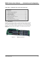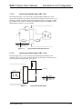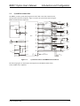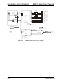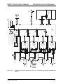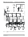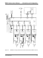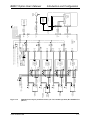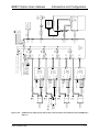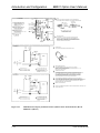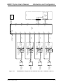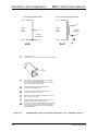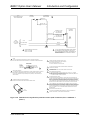
1
BB501 INTERFACE BOARD
OPTION MANUAL
P/N: EDO107 (V1.6)
AEROTECH, Inc. • 101 Zeta Drive • Pittsburgh, PA. 15238-2897 • USA
Phone (412) 963-7470 • Fax (412) 963-7459
Product Service: (412) 967-6440; (412) 967-6870 (Fax)
www.aerotech.com
Our web site is continually updated with new product information, manual updates, free downloadable software,
and special pricing on selected products. If you should have any questions about the BB501 board or comments
regarding the documentation, please refer to Aerotech online at:
http://www.aerotech.com.
For your convenience, a product registration form is available at our web site.
The BB501, UNIDEX 500, UNIDEX 600 PC-based motion controllers are products of Aerotech, Inc.
The BB501 Interface Board Option User’s Manual Revision History:
Rev 1.0
Rev 1.1
Rev 1.2
Rev 1.3
Rev 1.4
Rev 1.5
Rev 1.6
© Aerotech, Inc., 2004
January 22, 1995
April 16, 1998
December 28, 1999
March 28, 2000
September 13, 2000
May 2, 2001
July 7, 2004
BB501 Option User’s Manual
Table of Contents
TABLE OF CONTENTS
CHAPTER 1:
1.1.
1.2.
1.3.
1.4.
1.5.
1.6.
1.7.
1.8.
1.9.
1.10.
INTRODUCTION AND CONFIGURATION ...............................1-1
Introduction.........................................................................................1-1
Safety Procedures and Warnings ........................................................1-2
Unpacking the BB501 Board ..............................................................1-3
Mechanical Installation .......................................................................1-4
Electrical Installation ..........................................................................1-5
Hardware Configurations....................................................................1-6
1.6.1. BB501 Interface Board Jumper Configurations ...................1-7
1.6.2. BB501 Interface Board Test Points ....................................1-10
BB501 Interface Board Connectors ..................................................1-11
1.7.1. U500/U600 Interface Connector (J1) .................................1-11
1.7.2. Axis Feedback Connectors (J2-J5) .....................................1-13
1.7.3. Axis Amp Connectors (J6-J9) ............................................1-13
1.7.4. U500 I/O Hall Effect Connector (J10)................................1-14
1.7.5. U600 ISA I/O Hall Effect Connector (J10) ........................1-15
1.7.6. Digital I/O Connector (J11) ................................................1-16
1.7.7. Joystick Connector (J12) ....................................................1-18
1.7.8. Brake Connector (J14)........................................................1-18
1.7.9. Miscellaneous I/O Connector (TB1) ..................................1-19
1.7.9.1. Opto-Isolated Limit Inputs (J13) ......................1-20
1.7.9.2. Opto-Isolated Enable Input (TB1, 9-10)...........1-21
1.7.9.3. Opto-Isolated Fault Output (TB1, 11-12) .........1-21
1.7.10. External Power Supply Connector (TB2)...........................1-22
1.7.11. D/A Output Connector (TB3).............................................1-22
1.7.12. U600 Miscellaneous Connector (TB4) ...............................1-23
Power Requirements .........................................................................1-24
System Interconnections ...................................................................1-25
Troubleshooting and Technical Support ...........................................1-49
1.10.1. Common Problems and Causes ..........................................1-49
1.10.2. +5 Volt Supply ...................................................................1-50
1.10.3. Connectors ..........................................................................1-50
1.10.4. Technical Support...............................................................1-50
APPENDIX A: GLOSSARY OF TERMS................................................................A-1
APPENDIX B: WARRANTY AND FIELD SERVICE .......................................... B-1
APPENDIX C: TECHNICAL CHANGES...............................................................C-1
C.1.
C.2.
Current Changes (Manual V1.6)....................................................... C-1
Archive of Changes ........................................................................... C-2
INDEX
∇ ∇ ∇
www.aerotech.com
iii
Table of Contents
iv
BB501 Option User’s Manual
www.aerotech.com
BB501 Option User’s Manual
List of Figures
LIST OF FIGURES
Figure 1-1.
Figure 1-2.
Figure 1-3.
Figure 1-4.
Figure 1-5.
Figure 1-6.
Figure 1-7.
Figure 1-8.
Figure 1-9.
Figure 1-10.
Figure 1-11.
Figure 1-12.
Figure 1-13.
Figure 1-14.
Figure 1-15.
Figure 1-16.
Figure 1-17.
Figure 1-18.
Figure 1-19.
Figure 1-20.
Figure 1-21.
Figure 1-22.
Figure 1-23.
Figure 1-24.
Figure 1-25.
Figure 1-26.
Figure 1-27.
Figure 1-28.
Figure 1-29.
Figure 1-30.
BB501 Interface Board .......................................................................1-1
Mounting the BB501 Interface Board.................................................1-4
BB501 Interface Board Dimensions ...................................................1-4
BB501 Interface Board (Connector and Jumper Locations)...............1-6
Opto-Isolated Inputs .........................................................................1-20
Opto-Isolated Enable Input Interface................................................1-21
Opto-Isolated Fault Output ...............................................................1-21
System Interconnect with BB501 Breakout Board ...........................1-25
U500PCI System Interconnect w/ Steppers ......................................1-26
U500/BA Series Amps System Interconnect (115 VAC Offline Operation) Rev B 620D1273-1 (Sheet 1) ..................................1-27
U500/BA Series Amps System Interconnect (115 VAC Offline Operation) Rev B 620D1273-1 (Sheet 2) ..................................1-28
U500/BA Series Amps System Interconnect (230 VAC Offline Operation) Rev B 620D1273-2 (Sheet 1) ..................................1-29
U500/BA Series Amps System Interconnect (230 VAC Offline Operation) Rev B 620D1273-2 (Sheet 2) ..................................1-30
U500/BA Series Amps System Interconnect (with
Transformer) Rev B 620D1273-3 (Sheet 1) .....................................1-31
U500/BA Series Amps System Interconnect (with
Transformer) Rev B 620D1273-3 (Sheet 2) .....................................1-32
U600/BA Series Amps System Interconnect (115 VAC Offline Operation) Rev B 620D1276-1 (Sheet 1) ..................................1-33
U600/BA Series Amps System Interconnect (115 VAC Offline Operation) Rev B 620D1276-1 (Sheet 2) ..................................1-34
U600/BA Series Amps System Interconnect (230 VAC Offline Operation) Rev B 620D1276-2 (Sheet 1) ..................................1-35
U600/BA Series Amps System Interconnect (230 VAC Offline Operation) Rev B 620D1276-2 (Sheet 2) ..................................1-36
U600/BA Series Amps System Interconnect (with
TV.03/TV.04 Transformer) Rev B 620D1276-3 (Sheet 1)...............1-37
U600/BA Series Amps System Interconnect (with
TV.03/TV.04 Transformer) Rev B 620D1276-3 (Sheet 2)...............1-38
U500/BB501/BA Amps System with DC Brush Motors, Rev
A 620D1285-1 (Sheet 1)...................................................................1-39
U500/BB501/BA Amps System with DC Brush Motors, Rev
A 620D1285-1 (Sheet 2)...................................................................1-40
U500/BA Series Amps Brush System Interconnect, Rev A
620D1285-2 (Sheet 1).......................................................................1-41
U500/BA Series Amps Brush System Interconnect, Rev A
620D1285-2 (Sheet 2).......................................................................1-42
U600/BA Series Amps Brush System Interconnect (with
Transformer) Rev O 620D1301-1 (Sheet 1) .....................................1-43
U600/BA Series Amps Brush System Interconnect (with
Transformer) Rev O 620D1301-1 (Sheet 2) .....................................1-44
U600/BA Series Amps Brush System Interconnect (with
Transformer) Rev O 620D1301-1 (Sheet 3) .....................................1-45
BB501 Interface Board Schematic Rev D 690D1504 (Sheet 1) .......1-46
BB501 Interface Board Schematic Rev D 690D1504 (Sheet 2) .......1-47
www.aerotech.com
v
List of Figures
BB501 Option User’s Manual
Figure 1-31.
BB501 Interface Board Schematic Rev D 690D1504 (Sheet 3) ...... 1-48
∇ ∇ ∇
vi
www.aerotech.com
BB501 Option User’s Manual
List of Tables
LIST OF TABLES
Table 1-1.
Table 1-2.
Table 1-3.
Table 1-4.
Table 1-5.
Table 1-6.
Table 1-7.
Table 1-8.
Table 1-9.
Table 1-10.
Table 1-11.
Table 1-12.
Table 1-13.
Table 1-14.
Table 1-15.
Table 1-16.
Table 1-17.
BB501 Jumper Descriptions ...............................................................1-7
BB501 Test Points ............................................................................1-10
BB501 U500/U600 ISA Interface Connector (J1) Pinouts...............1-12
BB501 Encoder Feedback Connectors (J2-J5) Pinouts ....................1-13
BB501 Axis Amp Connectors (J6 - J9) Pinouts ...............................1-13
U500 I/O Hall Effect Connector (J10) Pinouts.................................1-14
U600 I/O Hall Effect Connector (J10) Pinouts.................................1-15
BB501 Digital I/O Connector (J11) Pinouts with U500 ...................1-16
BB501 Digital I/O Connector (J11) Pinouts with U600 ...................1-17
BB501 Joystick Connector (J12) Pinouts .........................................1-18
BB501 Brake Connector (J14) Pinouts.............................................1-18
BB501 Miscellaneous I/O Connector (TB1) Pinouts........................1-19
BB501 Opto-Isolated Connector Inputs (J13) Pinouts .....................1-20
BB501 External Power Supply Connector (TB2) Pinouts................1-22
BB501 D/A Output Connector (TB3) Pinouts..................................1-22
BB501 U600 Miscellaneous Connector (TB4) Pinouts ....................1-23
Problems and Causes ........................................................................1-49
∇ ∇ ∇
www.aerotech.com
vii
List of Tables
viii
BB501 Option User’s Manual
www.aerotech.com
BB501 Option User’s Manual
Introduction and Configuration
CHAPTER 1: INTRODUCTION AND CONFIGURATION
In This Section:
• Introduction ............................................................................1-1
• Safety Procedures and Warnings .............................................1-2
• Unpacking the BB501 Board...................................................1-3
• Mechanical Installation............................................................1-4
• Electrical Installation ...............................................................1-5
• Hardware Configurations ........................................................1-6
• BB501 Interface Board Connectors.......................................1-11
• Power Requirements..............................................................1-24
• System Interconnections........................................................1-25
• Troubleshooting and Technical Support................................1-49
1.1.
Introduction
The BB501 Interface Board (see Figure 1-1) provides the ability to interface an Aerotech
U500 or U600 control board to Aerotech’s BA Series drives. This board provides four
axes of amplifier and feedback connectors, a joystick port, several I/O and miscellaneous
signal ports, a power connector, and three U500/U600 connectors. Also contained on this
board are several jumpers that permit the BB501 to be configured for different options
and hardware.
Figure 1-1.
www.aerotech.com
BB501 Interface Board
1-1
Introduction and Configuration
1.2.
BB501 Option User’s Manual
Safety Procedures and Warnings
The following statements apply wherever the Warning or Danger symbol appears within
this manual. Failure to observe these precautions could result in serious injury to those
performing the procedures and/or damage to the equipment.
To minimize the risk of electrical shock and bodily injury, make certain that all of
the electrical power switches are in the off position prior to making any electrical
connections.
To minimize the risk of electrical shock and bodily injury when any electrical circuit
is in use, ensure that no person comes into contact with the circuitry.
When this controller is installed within a system, mechanical motion will
occur. Care must be exercised that all personnel remain clear of any moving parts.
To minimize the possibility of bodily injury, make certain that all electrical power
switches are in the off position prior to making any mechanical adjustments.
1-2
www.aerotech.com
BB501 Option User’s Manual
1.3.
Introduction and Configuration
Unpacking the BB501 Board
Before unpacking any components, visually inspect the container of the BB501 board for
any evidence of shipping damage. If any such damage exists, notify the shipping carrier
immediately.
All electronic equipment is wrapped in antistatic material and packaged with
desiccant (a drying agent used to reduce moisture). Make certain that the antistatic
material is not damaged during unpacking.
www.aerotech.com
1-3
Introduction and Configuration
1.4.
BB501 Option User’s Manual
Mechanical Installation
The BB501 interface board must be mounted in an area free of electrical noise. The
board is mounted using five .187” diameter mounting holes, refer to Figure 1-2 and
Figure 1-3.
Mounting Holes
TB2
TB1
TB3
TB4
BB501
Mounting Surface
Figure 1-2.
Mounting the BB501 Interface Board
Using a metal enclosure will help minimize any electrical noise pickup.
The BB501 can be mounted horizontally or vertically on a panel or wall.
Figure 1-3.
1-4
BB501 Interface Board Dimensions
www.aerotech.com
BB501 Option User’s Manual
1.5.
Introduction and Configuration
Electrical Installation
The electrical installation is dependent on the user's system and options. Each Axis
requires an amplifier connection (J6-J9) and a feedback connection (J2-J5). Refer to
Figure 1-4. Additional connections are required to utilize other available options such as
brake, joystick, miscellaneous I/O, or external power supply. Additional installation
information can be found in the hardware section of this manual and in other Aerotech
product manuals.
To minimize the risk of electrical shock and bodily injury, make certain that all of
the electrical power switches are in the off position prior to making any electrical
connections.
www.aerotech.com
1-5
Introduction and Configuration
1.6.
BB501 Option User’s Manual
Hardware Configurations
This section describes the configuration, power, and system interconnects requirements
for the BB501 interface board. This section contains a description of the jumper
configurations and connector pinouts for system interfacing.
J12 Joystick
J14 Brake
TB1
TB4
J14
JP1
JP3
JP31
JP30
J12
J13 Opto Isolated
Limit Inputs
J10 Hall Effect
Feedback
J11 Digital I/O
J11
J10
J1
J1 Standard
4-Axis Interface
TB2
JP28
JP29
2
4
6
8
1
3
5
7
1
3
5
7
J3
4
JP23
JP20
Amplifier Interface
Connectors
4
J8
Axis Feedback
Connectors
1
JP19
1
JP18
JP22
1
JP17
1
1
JP16
1
1
JP15
1
1
JP14
1
1
JP13
1
1
JP12
JP21
1
JP11
3
J7
JP27
3
1
1
JP10
J6
Test Points
9
4
10
5
11
6
12
7
8
1
1
JP9
1
1
JP8
1
1
JP7
2
J5
JP26
2
1
1
JP6
1
1
JP5
1
1
JP4
1
1
1
1
1
J4
JP25
JP24
1
JP35
JP34
JP33
JP32
2
4
6
8
J2
J9
TB3
Test Points
Figure 1-4.
1-6
BB501 Interface Board (Connector and Jumper Locations)
www.aerotech.com
BB501 Option User’s Manual
Introduction and Configuration
1.6.1. BB501 Interface Board Jumper Configurations
The BB501 contains configuration jumpers used to configure the axis and certain
options. Table 1-1 is a list of the jumpers on the BB501 interface board. Refer to
Figure 1-4 for jumper locations.
Table 1-1.
Jumper
JP1
JP3
JP4
JP5
JP6
JP7
JP8
JP9
JP10
JP11
JP12
JP13
JP14
BB501 Jumper Descriptions
Setting
Description
1-2
External global enable required
2-3 (default)
External global enable defeated
1-2 (default)
Brake Control from Brake (J1-96)
2-3
Brake Control from Out 0 (J1-63)
1-2 (default)
2-3
1-2 (default)
2-3
1-2 (default)
2-3
1-2
2-3 (default)
1-2 (default)
2-3
1-2 (default)
2-3
1-2 (default)
2-3
1-2
2-3 (default)
1-2 (default)
2-3
1-2 (default)
2-3
1-2 (default)
2-3
www.aerotech.com
Axis #1 External fault input defeated (J2-2 is Gnd)
Axis #1 External fault input enabled
Axis #1 Encoder +5V (J2-3) from J6- 2, 20 (amp)
Axis #1 Encoder +5V (J2-3) from TB2-2
Axis #1 Limit +5V (J2-16) from J6- 2, 20 (amp)
Axis #1 Limit +5V (J2-16) from TB2-4
Axis #1 ICMD1B to Amplifier –Input1 (J6-21)
Axis #1 ICMD1B to Amplifier +Input1 (J6-8)
Note: Setting JP7 to 1-2 requires JP24 to be set to 2-3.
Axis #2 External fault input defeated (J3-2 is Gnd)
Axis #2 External fault input enabled
Axis #2 Encoder +5V (J3-3) from J7- 2, 20 (amp)
Axis #2 Encoder +5V (J3-3) from TB2-2
Axis #2 Limit +5V (J3-16) from J7- 2, 20 (amp)
Axis #2 Limit +5V (J3-16) from TB2-4
Axis #2 ICMD2B to Amplifier -Input2 (J7-21)
Axis #2 ICMD2B to Amplifier +Input2 (J7-8)
Note: Setting JP11 to 1-2 requires JP25 to be set to 2-3.
Axis #3 External fault input defeated (J4-2 is Gnd)
Axis #3 External fault input enabled
Axis #3 Encoder +5V (J4-3) from J8- 2, 20 (amp)
Axis #3 Encoder +5V (J4-3) from TB2-2
Axis #3 Limit +5V (J4-16) from J8- 2, 20 (amp)
Axis #3 Limit +5V (J4-16) from TB2-4
1-7
Introduction and Configuration
Table 1-1.
Jumper
JP15
JP16
JP17
JP18
JP19
JP20
JP21
JP22
JP23
JP28 and JP29 pin #’s
are incorrectly labeled
on some Rev. D
boards.
See Figure 1-4 for
correct identification.
1-8
BB501 Option User’s Manual
BB501 Jumper Descriptions (Continued)
Setting
1-2
2-3 (default)
1-2 (default)
2-3
1-2 (default)
2-3
1-2 (default)
2-3
1-2
2-3 (default)
1-2 (default)
2-3
1-2 (default)
2-3
1-2 (default)
2-3
1-2 (default)
2-3
JP24
1-2 (default)
2-3
JP25
1-2 (default)
2-3
JP26
1-2 (default)
2-3
JP27
1-2 (default)
2-3
JP28
1-2
3-4
5-6
7-8
JP29
1-2
3-4
5-6
7-8
Description
Axis #3 ICMD3B to Amplifier –Input3 (J8-21)
Axis #3 ICMD3B to Amplifier +Input3 (J8-8)
Note: Setting JP15 to 1-2 requires JP26 to be set to 2-3.
Axis #4 External fault input defeated (J5-2 is Gnd)
Axis #4 External fault input enabled
Axis #4 Encoder +5V (J5-3) from J9- 2, 20 (amp)
Axis #4 Encoder +5V (J5-3) from TB2-2
Axis #4 Limit +5V (J5-16) from J9- 2, 20 (amp)
Axis #4 Limit +5V (J5-16) from TB2-4
Axis #4 ICMD4B to Amplifier -Input4 (J9-21)
Axis #4 ICMD4B to Amplifier +Input4 (J9-8)
Note: Setting JP19 to 1-2 requires JP27 to be set to 2-3.
Axis #1 Amp Fault (J6-23) enabled
Axis #1 Amp Fault(J6-23) defeated
Axis #2 Amp Fault (J7-23) enabled
Axis #2 Amp Fault (J7-23) defeated
Axis #3 Amp Fault (J8-23) enabled
Axis #3 Amp Fault (J8-23) defeated
Axis #4 Amp Fault (J9-23) enabled
Axis #4 Amp Fault (J9-23) defeated
Axis #1 - Input1 (J6-21) connected to common
Axis #1 - Input1 (J6-21) not connected to common
Note: Setting JP24 to 1-2 requires JP7 to be set to 2-3.
Axis #2 - Input2 (J7-21) connected to common
Axis #2 - Input2 (J7-21) not connected to common
Note: Setting JP25 to 1-2 requires JP11 to be set to 2-3.
Axis #3 - Input3 (J8-21) connected to common
Axis #3 - Input3 (J8-21) not connected to common
Note: Setting JP26 to 1-2 requires JP15 to be set to 2-3.
Axis #4 - Input3 (J9-21) connected to common
Axis #4 - Input3 (J9-21) not connected to common
Note: Setting JP27 to 1-2 requires JP19 to be set to 2-3.
IN, to connect Brake + power to Axis 1 (J2-25)
IN, to connect Brake + power to Axis 2 (J3-25)
IN, to connect Brake + power to Axis 3 (J4-25)
IN, to connect Brake + power to Axis 4 (J5-25)
Note: JP28 and JP29 are normally set the same.
IN, to connect Brake - power to Axis 1 (J2-13)
IN, to connect Brake - power to Axis 2 (J3-13)
IN, to connect Brake - power to Axis 3 (J4-13)
IN, to connect Brake - power to Axis 4 (J5-13)
Note: JP28 and JP29 are normally set the same.
www.aerotech.com
BB501 Option User’s Manual
Table 1-1.
BB501 Jumper Descriptions (Continued)
Jumper
Setting
JP30
(see note)
1-2 (default)
JP31
(see note)
1-2 (default)
JP32
JP33
JP34
JP35
Introduction and Configuration
2-3
Description
U600/U500 ISA
U500 PCI Ext. DAC common (TB3-10)
U600/U500 ISA
2-3
U500 PCI Ext. DAC common (TB3-10)
1-2
Axis 4 Ext. Disable input Active Low
2-3
Axis 4 Ext. Disable input Active High
1-2
Axis 1 Ext. Disable input Active Low
2-3
Axis 1 Ext. Disable input Active High
1-2
Axis 2 Ext. Disable input Active Low
2-3
Axis 2 Ext. Disable input Active High
1-2
Axis 3 Ext. Disable input Active Low
2-3
Axis 3 Ext. Disable input Active High
JP30, JP31 are set 2-3 only for U500 PCI, and if you are using an external power
supply for the DAC outputs. See the U500 manual for the required jumper settings
on the U500 PCI as well.
JP28 and JP29 Pin Numbers are incorrectly labeled on some Rev. D boards. See
Figure 1-4 for correct identification.
www.aerotech.com
1-9
Introduction and Configuration
1.6.2. BB501 Interface Board Test Points
TB1
Test points are located on the top side of the BB501 board near terminal block TB3
(Figure 1-4). These test points provide easy access to critical signals on the BB501
board. Table 1-2 lists the test points and their description.
TB4
Table 1-2.
BB501 Test Points
Test Points
TB2
Test Points
9
4
10
5
11
6
12
7
8
T est P oints
9
4
5
10
6
11
12
7
8
1-10
BB501 Option User’s Manual
TB3
Description
TP4
Ground
TP5
Axis #1 Amplifier ICMD1 (J6-25)
TP6
Axis #1 Amplifier IFDBK1
TP7
Axis #2 Amplifier ICMD2 (J7-25)
TP8
Axis #2 Amplifier IFDBK2
TP9
Axis #3 Amplifier ICMD3 (J8-25)
TP10
Axis #3 Amplifier IFDBK3
TP11
Axis #4 Amplifier ICMD4 (J9-25)
TP12
Axis #4 Amplifier IFDBK4
(J6-12)
(J7-12)
(J8-12)
(J9-12)
www.aerotech.com
BB501 Option User’s Manual
1.7.
Introduction and Configuration
BB501 Interface Board Connectors
The BB501 board contains seventeen connectors consisting of two U500/U600 interface
connectors, four amp connectors, four encoder connectors, three I/O connectors, one D/A
connector, one joystick connector, one brake connector, and an external power supply
connector. The following sections describe the pinouts for each of these connectors.
1.7.1. U500/U600 Interface Connector (J1)
The U500/U600 Interface connector is a 100-pin “AMPLIMITE” connector that
provides the majority of the signals to and from the U500 or U600 control board. Refer
to Table 1-3 for a description of the pinouts for connector J1.
www.aerotech.com
1-11
Introduction and Configuration
Table 1-3.
BB501 Option User’s Manual
BB501 U500/U600 ISA Interface Connector (J1) Pinouts
Pin Function
Description
Pin Function
Description
1
3
5
7
9
11
13
15
17
19
21
23
25
27
29
31
33
35
37
39
41
43
45
47
49
51
53
55
57
59
61
63
65
67
69
71
73
75
77
79
81
83
85
87
89
91
93
95
97
99
ILOCKS(Gnd)
+5
GND
SIN1+
COS1+
MRK1+
GND
SIN2+
COS2+
MRK2+
GND
SIN3+
COS3+
MRK3+
GND
SIN4+
COS4+
MRK4+
GND
CW1
CW2
CW3
CW4
HOME1
HOME3
Reserved
+12V
-12V
Reserved
IN0
IN2
OUT0
OUT2
Reserved
AEN1
AEN3
AFLT1
AFLT3
GND
ICMD1B
ICMD2B
ICMD3B
ICMD4B
GND
JSW1 / AIN 1
JSA
JSC (JS I Lock)
AIN0
ESTOP
OPTOA
2
4
6
8
10
12
14
16
18
20
22
24
26
28
30
32
34
36
38
40
42
44
46
48
50
52
54
56
58
60
62
64
66
68
70
72
74
76
78
80
82
84
86
88
90
92
94
96
98
100
Reserved / Common
+5
GND
SIN1COS1MRK1GND
SIN2COS2MRK2GND
SIN3COS3MRK3GND
SIN4COS4MRK4GND
CCW1
CCW2
CCW3
CCW4
HOME2
HOME4
GND
+12V
-12V
Reserved
IN1
IN3
OUT1
OUT3
Reserved
AEN2
AEN4
AFLT2
AFLT4
GND
ICMD1A
ICMD2A
ICMD3A
ICMD4A
GND
JSW2 / AIN 2
JSB
BRAKE
AIN1
UINT
ILOCKR
1-12
Interlock Send
+5 Volts
Encoder Ground / Hall 1 B
Encoder SIN +, Axis 1
Encoder COS +, Axis 1
Marker +, Axis 1
Encoder Ground / Hall 2 B
Encoder SIN +, Axis 2
Encoder COS +, Axis 2
Marker +, Axis 2
Encoder Ground / Hall 2 C
Encoder SIN +, Axis 3
Encoder COS +, Axis 3
Marker +, Axis 3
Encoder Ground / Hall 3 A
Encoder SIN +, Axis 4
Encoder COS +, Axis 4
Marker +, Axis 4
Ground / Hall 4 B
CW Limit, Axis 1
CW Limit, Axis 2
CW Limit, Axis 3
CW Limit, Axis 4
Home Limit, Axis 1
Home Limit, Axis 3
Synchronization
DAC +12V In / PC +12V Out
DAC -12V In / PC -12V Out
Recirc. Axis 1(Reserved)
Input 0
Input 2
Output 0
Output 2
Recirc. Axis 3(Reserved)
Amplifier Enable 1
Amplifier Enable 3
Amplifier Fault 1
Amplifier Fault 3
Ground
Axis 1 Primary Current Cmd
Axis 2 Primary Current Cmd
Axis 3 Primary Current Cmd
Axis 4 Primary Current Cmd
Ground
Joystick Potentiometer 1 / AIN 1
Joystick Button A
Joystick Button C
Analog Input 0 / 3
Emergency Stop
Opto Anode for 97 & 98
(Reserved ) / Common
+5 Volts
Encoder Ground / Hall 1 A
Encoder SIN -, Axis 1
Encoder COS -, Axis 1
Marker -, Axis 1
Encoder Ground / Hall 2A
Encoder SIN -, Axis 2
Encoder COS -, Axis 2
Marker -, Axis 2
Encoder Ground / Hall 3 B
Encoder SIN -, Axis 3
Encoder COS -, Axis 3
Marker -, Axis 3
Encoder Ground / Hall 3 C
Encoder SIN -, Axis 4
Encoder COS -, Axis 4
Marker -, Axis 4
Ground / Hall 4 A
CCW Limit, Axis 1
CCW Limit, Axis 2
CCW Limit, Axis 3
CCW Limit, Axis 4
Home Limit, Axis 2
Home Limit, Axis 4
Ground / Hall 1 C
DAC Gnd. / PC +12V
DAC Gnd. / PC -12V
Recirc. Axis 2 (Reserved)
Input 1
Input 3
Output 1
Output 3
Recirc. Axis 4 (Reserved)
Amplifier Enable 2
Amplifier Enable 4
Amplifier Fault 2
Amplifier Fault 4
Ground
Axis 1 Secondary Current Cmd
Axis 2 Secondary Current Cmd
Axis 3 Secondary Current Cmd
Axis 4 Secondary Current Cmd
Ground / Hall 4 C
Joystick Potentiometer 2 / AIN 2
Joystick Button B
Brake Output
Analog Input 1 / 4
User Interrupt
Interlock Receive
www.aerotech.com
BB501 Option User’s Manual
Introduction and Configuration
1.7.2. Axis Feedback Connectors (J2-J5)
The BB501 interface board contains four encoder feedback connectors (J2-J5, one for
each axis). These connectors are 25-pin “D” type connectors and have the same pinouts
for each. The pinouts for the axis feedback connectors are listed in Table 1-4.
Table 1-4.
BB501 Encoder Feedback Connectors (J2-J5) Pinouts
Pin
Function
1
2
3
4
5
6
7
8
9
10
11
12
13
Shield
External Fault / Input
Encoder +5 Volts
Reserved
Hall Effect B
Marker Marker +
Ground
Reserved
Hall Effect A
Hall Effect C
Clockwise Limit
Brake Output
Description
Pin
SHIELD
EXTFLT
5V
Reserved
HB
MRKMRK+
GND
Reserved
HA
HC
CW
BRK-
14
15
16
17
18
19
20
21
22
23
24
25
Function
Description
COS +
COS Limit +5 Volts
SIN +
SIN Tach +
Ground
Ground
Home Limit
External Disable Input
Counter Clockwise Limit
Brake Output
COS+
COS5V
SIN+
SINTACH+
GND
GND
HMLMT
EXTDIS
CCW
BRK +
1.7.3. Axis Amp Connectors (J6-J9)
The BB501 interface board contains four amplifier connectors (J6-J9, one for each axis).
These connectors are 25-pin “D” type connectors and have the same pinouts for each.
The pinouts for the axis amplifier connectors are listed in Table 1-5.
Table 1-5.
BB501 Axis Amp Connectors (J6 - J9) Pinouts
Pin
Function
1
2
3
4
5
6
7
8
9
10
11
12
13
Shield
Amp +5V out
Tach +
Hall Effect A
COS +
COS Ground
+ Input
Current Cmd A
Axis Enable
Reserved
Current Feedback
PWM Osc.
www.aerotech.com
Description
SHIELD
5V
Tach +
HA
COS+
COS GND
+INPUT
ICMDA
ENABLE
Reserved
IFDBK
PWM
Pin
Function
14
15
16
17
18
19
20
21
22
23
24
25
Ground
Ground
Hall Effect B
Hall Effect C
SIN +
SIN Amp +5V out
- Input
Current Cmd B
Axis Fault
Reserved
ICMD from Amp.
Description
GND
GND
HB
HC
SIN+
SIN 5V
-INPUT
ICMDB
FAULT
Reserved
ICMD
1-13
Introduction and Configuration
BB501 Option User’s Manual
1.7.4. U500 I/O Hall Effect Connector (J10)
The U500 I/O Hall effect connector is a 50-pin ribbon type and is used for Hall effect
and additional I/O signals. This connector may not be required in all applications.
Table 1-6 lists the pinouts and descriptions for J10.
The mate to this connector is a 3M (P/N 3425-6050) or Aerotech (P/N ECK332).
Table 1-6.
Pin
1-14
U500 I/O Hall Effect Connector (J10) Pinouts
Function
Description
Pin
Function
Description
1
Input 15 / Hall-4C
I15/HC4
2
Ground
GND
3
Input 14 / Hall-4A
I14/HA4
4
Ground
GND
5
Input 13 / Hall-4B
I13/HB4
6
Ground
GND
7
Input 12 / Hall-3C
I12/HC3
8
Ground
GND
9
Input 11 / Hall-3A
I11/HA3
10
Ground
GND
11
Input 10 / Hall-3B
I10/HB3
12
Ground
GND
13
Input 9 / Hall-2C
I9/HC2
14
Ground
GND
15
Input 8 / Hall-2A
I8/HA2
16
Ground
GND
17
Input 7 / Hall-2B
I7/HB2
18
Ground
GND
19
Input 6 / Hall-1C
I6/HC1
20
Ground
GND
21
Input 5 / Hall-1A
I5/HA1
22
Ground
GND
23
Input 4 / Hall-1B
I4/HB1
24
Ground
GND
25
Input 3
IN3
26
Ground
GND
27
Input 2
IN2
28
Ground
GND
29
Input 1
IN1
30
Ground
GND
31
Input 0
IN0
32
Ground
GND
33
Output 7
OUT7
34
Ground
GND
35
Output 6
OUT6
36
Ground
GND
37
Output 5
OUT5
38
Ground
GND
39
Output 4
OUT4
40
Ground
GND
41
Output 3
OUT3
42
Ground
GND
43
Output 2
OUT2
44
Ground
GND
45
Output 1
OUT1
46
Ground
GND
47
Output 0
OUT0
48
Ground
GND
49
+5 Volts
+5
50
Ground
GND
www.aerotech.com
BB501 Option User’s Manual
Introduction and Configuration
1.7.5. U600 ISA I/O Hall Effect Connector (J10)
The U600 ISA I/O Hall effect connector is a 50-pin ribbon type and is used for Hall
effect and additional I/O signals. This connector may not be required in all applications.
Table 1-7 lists the pinouts and descriptions for J10.
The mate to this connector is a 3M (P/N 3425-6050) or Aerotech (P/N ECK332).
Table 1-7.
Pin
U600 I/O Hall Effect Connector (J10) Pinouts
Function
Description
Pin
Function
Description
1
Hall-4C
HC4
2
Ground
GND
3
Hall-4A
HA4
4
Ground
GND
5
Hall-4B
HB4
6
Ground
GND
7
Hall-3C
HC3
8
Ground
GND
9
Hall-3A
HA3
10
Ground
GND
11
Hall-3B
HB3
12
Ground
GND
13
Hall-2C
HC2
14
Ground
GND
15
Hall-2A
HA2
16
Ground
GND
17
Hall-2B
HB2
18
Ground
GND
19
Hall-1C
HC1
20
Ground
GND
21
Hall-1A
HA1
22
Ground
GND
23
Hall-1B
HB1
24
Ground
GND
25
User Reset Input
RSTIN
26
Ground
GND
27
Position Latch Input
PLATCH
28
Ground
GND
29
Reserved Output 1
ROUT1
30
Ground
GND
31
Reserved Output 2
ROUT2
32
Ground
GND
33
Output 15
OUT15
34
Ground
GND
35
Output 14
OUT14
36
Ground
GND
37
Output 13
OUT13
38
Ground
GND
39
Output 12
OUT12
40
Ground
GND
41
Output 3
OUT3
42
Ground
GND
43
Output 2
OUT2
44
Ground
GND
45
Output 1
OUT1
46
Ground
GND
47
Output 0
OUT0
48
Ground
GND
49
+5 Volts
+5
50
Ground
GND
www.aerotech.com
1-15
Introduction and Configuration
BB501 Option User’s Manual
1.7.6. Digital I/O Connector (J11)
The Digital I/O connector (J11) is a 50-pin “Champ” connector and is the digital
input/output port. Table 1-8 lists the pinouts for the digital I/O connector J11 when
interfacing with the U500. Table 1-9 lists the pinouts when interfacing with the U600.
The mate to this connector is a 3M (P/N 3564-1001) or Aerotech (P/N ECK353).
Table 1-8.
1-16
BB501 Digital I/O Connector (J11) Pinouts with U500
Pin
Function
Description
Pin
1
Function
Description
Hall Effect C4 / Input 15
HC4/I15
26
Ground
GND
2
Hall Effect A4 / Input 14
HA4/I14
27
Ground
GND
3
Hall Effect B4 / Input 13
HB4/I13
28
Ground
GND
4
Hall Effect C3 / Input 12
HC3/I12
29
Ground
GND
5
Hall Effect A3 / Input 11
HA3/I11
30
Ground
GND
6
Hall Effect B3 / Input 10
HB3/I10
31
Ground
GND
7
Hall Effect C2 / Input 9
HC2/I9
32
Ground
GND
8
Hall Effect A2 / Input 8
HA2/I8
33
Ground
GND
9
Hall Effect B2 / Input 7
HB2/I7
34
Ground
GND
10
Hall Effect C1 / Input 6
HC1/I6
35
Ground
GND
11
Hall Effect A1 / Input 5
HA1/I5
36
Ground
GND
12
Hall Effect B1 / Input 4
HB1/I4
37
Ground
GND
13
Input 3
IN3
38
Ground
GND
14
Input 2
IN2
39
Ground
GND
15
Input 1
IN1
40
Ground
GND
16
Input 0
IN0
41
Ground
GND
17
Output 7
OUT7
42
Ground
GND
18
Output 6
OUT6
43
Ground
GND
19
Output 5
OUT5
44
Ground
GND
20
Output 4
OUT4
45
Ground
GND
21
Output 3
OUT3
46
Ground
GND
22
Output 2
OUT2
47
Ground
GND
23
Output 1
OUT1
48
Ground
GND
24
Output 0
OUT0
49
Ground
GND
25
+5 Volts
+5V
50
Ground
GND
www.aerotech.com
BB501 Option User’s Manual
Table 1-9.
Pin
Introduction and Configuration
BB501 Digital I/O Connector (J11) Pinouts with U600
Function
Description
Pin
Function
Description
1
Hall Effect C4
HC4
26
Ground
GND
2
Hall Effect A4
HA4
27
Ground
GND
3
Hall Effect B4
HB4
28
Ground
GND
4
Hall Effect C3
HC3
29
Ground
GND
5
Hall Effect A3
HA3
30
Ground
GND
6
Hall Effect B3
HB3
31
Ground
GND
7
Hall Effect C2
HC2
32
Ground
GND
8
Hall Effect A2
HA2
33
Ground
GND
9
Hall Effect B2
HB2
34
Ground
GND
10
Hall Effect C1
HC1
35
Ground
GND
11
Hall Effect A1
HA1
36
Ground
GND
12
Hall Effect B1
HB1
37
Ground
GND
13
Input 3
IN3
38
Ground
GND
14
Input 2
IN2
39
Ground
GND
15
Input 1
IN1
40
Ground
GND
16
Input 0
IN0
41
Ground
GND
17
Output 15
OUT15
42
Ground
GND
18
Output 14
OUT14
43
Ground
GND
19
Output 13
OUT13
44
Ground
GND
20
Output 12
OUT12
45
Ground
GND
21
Output 3
OUT3
46
Ground
GND
22
Output 2
OUT2
47
Ground
GND
23
Output 1
OUT1
48
Ground
GND
24
Output 0
OUT0
49
Ground
GND
25
+5 Volts
+5V
50
Ground
GND
www.aerotech.com
1-17
Introduction and Configuration
BB501 Option User’s Manual
1.7.7. Joystick Connector (J12)
The joystick connector (J12) is a 5-pin “D” type connector. This connector contains the
joystick wiper and button signals. The pinouts for the joystick connector are listed in
Table 1-10.
Table 1-10.
Pin
1
2
3
4
5
6
7
8
BB501 Joystick Connector (J12) Pinouts
Function
+5 Volts
Joystick Button A
Joystick Wiper 1
Ground
Reserved
Joystick Wiper 2
Joystick Button B
Reserved
Description
Pin
Function
+5V
JSA
JSW1
GND
Reserved
JSW2
JSB
Reserved
9
10
11
12
13
14
15
Reserved
Reserved
Reserved
Reserved
Joystick Interlock
Reserved
Reserved
Description
Reserved
Reserved
Reserved
Reserved
JSI
Reserved
Reserved
1.7.8. Brake Connector (J14)
The brake connector (J14) is a 6-pin “IDC” locking connector and provides a brake
control signal. The pinouts for the brake connector are listed in Table 1-11.
The mate to this connector in an Amp (P/N 640440-6 and 640550-6) or an Aerotech (P/N
EIK297 and EIK298).
Table 1-11.
Pin
1
2
3
4
5
6
1-18
BB501 Brake Connector (J14) Pinouts
Function
+5 Volts
Ground
Brake (control signal)
Ground
Reserved
Ground
Description
+5V
GND
BRAKE
GND
Reserved
GND
www.aerotech.com
BB501 Option User’s Manual
Introduction and Configuration
1.7.9. Miscellaneous I/O Connector (TB1)
The Miscellaneous I/O connector (TB1) is a 12-pin terminal board connector. This
connector provides various system control and input signals. The pinouts for the
Miscellaneous I/O connector are listed in Table 1-12.
Table 1-12.
Pin
1
2
3
4
5
6
7
8
9
10
11
12
BB501 Miscellaneous I/O Connector (TB1) Pinouts
Function
Shield
Ground
1st Analog Input
2nd Analog Input
Brake (control signal)
Emergency Stop
User Interrupt
Opto Anode
Enable Common
External Enable
Fault Common
Fault Out
www.aerotech.com
Description
SHIELD
GND
U600 Analog Input 0 / U500 $AD1 command
U600 Analog Input 1 / U500 $AD0 command
BRAKE
ESTOP
UINT
OPTOA
ENBCOM
EXTENB
FLTCOM
FLTOUT
1-19
Introduction and Configuration
1.7.9.1.
BB501 Option User’s Manual
Opto-Isolated Limit Inputs (J13)
The Opto-Isolated Limit Inputs connector (J13) is a 24 Pin terminal board connector.
This connector provides opto-isolated inputs for Axis 1-4, CW limits, CCW limits, and
Home limits. These inputs are used when isolation is required for the limit inputs.
Connectors J2, J3, J4, and J5 provide un-isolated connections for the limit inputs. These
limit connections must not be used when the Opto-Isolated Limit Inputs are used.
These opto-isolated inputs are configured for 12 – 24V logic level inputs. They have
3,900 Ohm series resistors limiting the current through the opto to 5mA. An external
series resistor should be used if a voltage greater than 24V is to be applied. Figure 1-5
shows the opto-isolator inputs for J13. The pinouts for the Opto-Isolated Limit Inputs
(J13) are listed in Table 1-13.
Table 1-13.
Pin
1
2
3
4
5
6
7
8
9
10
11
12
BB501 Opto-Isolated Connector Inputs (J13) Pinouts
Description
Pin
Axis 1 CW LMT +
Axis 1 CW LMT Axis 1 CCW LMT +
Axis 1 CCW LMT Axis 1 Home LMT +
Axis 1 Home LMT Axis 2 CW LMT +
Axis 2 CW LMT Axis 2 CCW LMT +
Axis 2 CCW LMT Axis 2 Home LMT +
Axis 2 Home LMT -
Description
13
14
15
16
17
18
19
20
21
22
23
24
Axis 3 CW LMT +
Axis 3 CW LMT Axis 3 CCW LMT +
Axis 3 CCW LMT Axis 3 Home LMT +
Axis 3 Home LMT Axis 4 CW LMT +
Axis 4 CW LMT Axis 4 CCW LMT +
Axis 4 CCW LMT Axis 4 Home LMT +
Axis 4 Home LMT -
J13
J13
J13
1
9
17 +
2
10
18 –
3
11
19 +
4
12
20 –
5
13
21 +
6
14
22 –
7
15
23 +
8
16
24 –
3.9 KΩ
IN4148
PS2501-4SK
(Only One Opto-Isolation Circuit is Shown)
Figure 1-5.
1-20
Opto-Isolated Inputs
www.aerotech.com
BB501 Option User’s Manual
1.7.9.2.
Introduction and Configuration
Opto-Isolated Enable Input (TB1, 9-10)
The enable input (TB1, 9-10) can be used as a global amplifier shutdown. It can be
connected to emergency stop circuit or safety interlock. Jumper JP1 must be set to 1-2 to
enable this function. A forward voltage must be applied to TB1, 9-10 in order to enable
the amplifiers. If the voltage is removed, all amplifiers connected to the BB501 will be
disabled. Refer to Figure 1-6 for an example.
DISABLE
ENABLE
TB1-9
6N136
6
2
+V
3
5
R
+V
5VDC
12VDC
24VDC
390
R
0
620 Ohms, ¼W
1500 Ohms, ½W
Figure 1-6.
1.7.9.3.
TB1-10
Opto-Isolated Enable Input Interface
Opto-Isolated Fault Output (TB1, 11-12)
The fault output (TB1, 11-12) is an optically isolated output that indicates a fault
condition. Figure 1-7 provides an example interface for this output. A fault on any axis
will cause the fault out signal (TB1-12) to go low.
R
TB1-12
OUTPUT
4N33
1
5
+V
2
4
TB1-11
Figure 1-7.
www.aerotech.com
+V
5VDC
12VDC
24VDC
RN (Typ.)
5.1K Ohms, ¼W
12K Ohms, ¼W
24K Ohms, ½W
Opto-Isolated Fault Output
1-21
Introduction and Configuration
BB501 Option User’s Manual
1.7.10. External Power Supply Connector (TB2)
The external power supply connector (TB2) is a 6-pin terminal board connector. This
connector provides connections for an external power supply to power the encoder and
limit circuits (possibly at a voltage other than 5 volts). The pinouts for the external power
supply connector are listed in Table 1-14.
Table 1-14.
BB501 External Power Supply Connector (TB2) Pinouts
Pin
Function
Description
1
2
3
4
5
Shield
Optional Encoder (power)
Ground
Optional Limit (power)
Ground
SHIELD
ENCDR (power)
GND
LIMIT (power)
GND
6
Reserved
Reserved
1.7.11. D/A Output Connector (TB3)
The D/A output connector (TB3) is a 12-pin terminal board connector. This connector
provides eight current command or D/A outputs (available as D/A output when not used
as current command on U500). The pinouts for the D/A Output connector are listed in
Table 1-15.
Table 1-15.
BB501 D/A Output Connector (TB3) Pinouts
Pin
Function
Description
1
2
3
4
5
6
7
8
9
10
11
12
Ground
Axis 1 Current Cmd. A
Axis 1 Current Cmd. B
Axis 2 Current Cmd. A
Axis 2 Current Cmd. B
Axis 3 Current Cmd. A
Axis 3 Current Cmd. B
Axis 4 Current Cmd. A
Axis 4 Current Cmd. B
Ground (Ext. DAC com.)
U500 PCI Ext. DAC +12V
U500 PCI Ext. DAC -12V
GND
ICMD1A
ICMD1B
ICMD2A
ICMD2B
ICMD3A
ICMD3B
ICMD4A
ICMD4B
GND
See Note
See Note
These are for use with the U500 PCI only. You must set jumpers JP30, JP31, and the
jumpers on the U500 PCI card appropriately. See the schematic (Figure 1-31).
1-22
www.aerotech.com
BB501 Option User’s Manual
Introduction and Configuration
1.7.12. U600 Miscellaneous Connector (TB4)
The U600 Miscellaneous connector (TB4) is a 12-pin terminal board connector. This
connector is used with the U600 and contains additional I/O signals. The pinouts for the
U600 Misc. connector are listed in Table 1-16.
Table 1-16.
BB501 U600 Miscellaneous Connector (TB4) Pinouts
Pin Function
Description
Pin Function
Description
1
Shield
SHIELD
7
Reserved Output 1 (Emitter)
Out1-E
2
Ground
GND
8
Reserved Output 2 (Collector)
Out2-C
3
E-stop Opto Anode
OPTOA
9
Reserved Output 1 (Emitter)
Out2-E
4
User Reset Input
Reset
10
Reserved
Reserved
5
High Speed Position Latch
Pos Latch
11
+ Brake Supply
BRK +
6
Reserved Output 1 (Collector)
Out1-C
12
- Brake Supply
BRK-
www.aerotech.com
1-23
Introduction and Configuration
1.8.
BB501 Option User’s Manual
Power Requirements
The BB501 Interface board requires +5V at less than .5 amp that it obtains through the
main signal connector (P1). An additional 5-volt supply will be required to power the
encoder and limit circuitry if the opto-isolated inputs are used. If an external power
supply is required, it should meet the following minimum requirements.
The following current capacity requirement is for a typical system (some systems may
require higher amperage supplies):
+5 Volt Power Supply requirements:
Nominal Voltage (Min. - Max.)
Ripple (P-P Volts)
Current Capacity
- 4.9 Volts to 5.25 Volts
- less than 100mv P-P
- 1.0 Amps / Axis minimum. (typical).
- 4 Amps for 4 Axis (typical)
1-24
www.aerotech.com
BB501 Option User’s Manual
1.9.
Introduction and Configuration
System Interconnections
The BB501 provides system interfacing between the U600 or the U500 Control boards
and Aerotech’s BA Series amplifiers. Figure 1-8 shows the system interconnect using the
BB501 and the BA Series amplifiers.
J6
AXIS 1
AMP
U500/U600
OP500
P1
BAC
BA SERIES
AMPLIFIERS
P1 BA10
BA20
FRAME
/SHLD
A
MOTOR
AC
INPUT
J1
C
DRC
BFC 630C1529
(TYP.4 PLS.)
DIOSR
5 or 12 ft.
BAC
J7
AXIS 2
AMP
J10
Hall Effect
Signals
BA SERIES
AMPLIFIERS
P1 BA10
BA20
AXIS 1 (X)
LIMITS
AXIS 1 (X)
BRUSHLESS
MOTOR
FRAME
/SHLD
MOTOR
AC
INPUT
BB501
(TYP.4 PLS.)
GRN
LO BLU
HI BRN
J2
AXIS 1
FDBK
P5/P10
PNC 630C1580
OR
PNC 630C1381
GRN OR ORN
BLK
RED
WHT OR BRN
A
B
C
GRN
LO BLU
HI BRN
J3
AXIS 2
FDBK
AXIS 2 (Y)
LIMITS
AXIS 2 (Y)
BRUSHLESS
MOTOR
FRAME
/SHLD
JP4 EXTENSION CABLE
(OPTIONAL)
JBV
DIGITIZING
JOYSTICK
(OPTIONAL)
P1
BA SERIES
AMPLIFIERS
BA10
BA20
MOTOR
AC
INPUT
J12
JOYSTICK
A
B
C
GRN
LO BLU
HI BRN
J4
AXIS 3
FDBK
BRAKE
BOARD
AXIS 3 (Z)
LIMITS
AXIS 3 (Z)
BRUSHLESS
MOTOR
FRAME
/SHLD
J14
BRAKE
J1
TB1
AC
POWER
BAC
J8
AXIS 3
AMP
BRAKE POWER
SUPPLY
OPTO22 BOARD
PB8, PB16, PB24
(OPTIONAL)
1
11
2
12
TB4
MISC
–
OPC-5
(OPTIONAL)
J11
DIGITAL I/O
Figure 1-8.
BA SERIES
AMPLIFIERS
P1 BA10
BA20
MOTOR
AC
INPUT
A
B
C
GRN
LO BLU
HI BRN
J5
AXIS 4
FDBK
TB1
MISC. I/O
+
BAC
J9
AXIS 4
AMP
TB2
EXT PWR
SUPPLY
COM
AXIS 4 (U)
LIMITS
3
1
OPTIONAL
LOGIC COMMON TO FRAME
GROUND CONNECTION
GRN
BLU
BRN
AXIS 4 (U)
BRUSHLESS
MOTOR
SAFETY
GROUND A.C.
LO
INPUT
HI
115VAC
System Interconnect with BB501 Breakout Board
The following figures are interconnect drawings between the BB501 and the U500,
U600, and BA Series Amplifiers.
www.aerotech.com
1-25
Introduction and Configuration
BB501 Option User’s Manual
1 J1
AXIS 1
M O TOR
O U TPUT
P9 P8
U500PCI-ULTRA/P SO
690D1546
See ES12411-20
P1
OP500-5
P5
J2
AXIS 1
ENC /LMT
J1
From
U500
J1
J3
AXIS 2
ENC /LMT
DIOS R
630B1627
SR-2x 50DRH-100
690D1546
P1
630B1538
M X50- D-16M
X50 M U LT.
ES13210
OP500-12
J12
JO YST IC K
J13
M ISC.
I/O
J11
I/O BUS
AC
INL ET
BFCMX -15
630C1650-1
MX C-3
630B1538
M X50- D-16M
X50 M U LT.
ES13210
AX IS 2 (Y)
MOTOR
BFCMX -15
AX IS 2 (Y)
FEEDB ACK
630C1650-1
3 J1
AXIS 3
M O TOR
O U TPUT
BM CHPD-15
J4
AXIS 3
ENC /LMT
BFCMX -15
AX IS 3 (Z)
MOTOR
630C1695-1
AX IS 3 (Z)
FEEDB ACK
630C1650-1
BM CHPD-15
AX IS 4 (U)
MOTOR
630C1695-1
BFCMX -15
J5
AXIS 4
ENC /LMT
LINE CORD:
LCX116
AX IS 1 (X)
FEEDB ACK
630C1695-1
4 J1
AXIS 4
M O TOR
O U TPUT
P3 P2
AX IS 1 (X)
MOTOR
630C1695-1
2J1
AXIS 2
M O TO R
OU TPUT
DR500R-B- 160-160
/X 2-AS 32020C-F3.5
/X 2-AS 32020C-F1.8
620D1311-2
DRC-5
630B1628
BM CHPD-15
MX C-3
AX IS 4 (U)
FEEDB ACK
630C1650-1
TO AX IS 1 (X )
ALS 20010-M-10LT10AS-NC- XYCM S
E1418602
TO AX IS 2 (Y )
ALS 20010-M-10LT10AS-NC
E1418602
TO AX IS 3 (Z)
AV S105-M -BMS -NC
E1418603
TO AX IS 4 (U )
ART310-M-G54-B MSHC-RB 310M
E1418603
230VA C @ 5A
CUSTOMER P.C.
O PTO -2 2 G 4PB24
M O UN TIN G RAC K
POSITION 0- 7 = G4O DC 5
POSITION 8- 23 = G 4ID C5
U500PCI S YSTEM
IN TER CONNE CT
E1418601
REV -
J6
AX IS 1
AM P
J1
TO
U500 / U600
P1
TB1
MISC. I/O
PDS 13-2
DRIVE CABLE
E1418607
AC
IN LE T
PDS 13-2
STEP PER DRIV E
See ES14186
FOR SE T-UP
M OTOR
BB 501
690D1504
See ES14186
CONTROL
110 - 240VA C @ 2A
AX IS 5 ( A)
ATS50-25-M-1
E1418606
J2
AX IS 1
FDBK
USE R P SO INTE RFACE
U500
P9-44
P9-47
P9-48
P9-49
Figure 1-9.
1-26
Description
TTL Fire Out (TB1-2 COM)
Las er Com mon
Las er Fire Output
Las er +5V
BB501
TB1-5
TB1-6
TB1-7
TB1-8
U500PCI System Interconnect w/ Steppers
www.aerotech.com
U500
P5
CUSTOMER P.C.
P1
DIOSR (STD)
630B1627
OP500
5 OR 12 FT
DRC (STD)
630B1628
5 OR 12 FT
JP4 EXTENSION CABLE
630B1505
(OPTIONAL)
OPC-5
630B1358 LENGTH A.R.
(OPTIONAL)
8
J1
TO
U500/U600
P1
J10
I/OHALL
EFFECT
J12
JOYSTICK
TB1
MISC. I/O
J11
DIGITAL
I/O
2 4
6 1 3
J14 BRAKE
5
BB501
11
2
JP29
11
JP29
1
3
2 JP28 1
4
11
JP29
5
4 JP28 3
6
11
JP29
7
6 JP28 5
8
8 JP28 7
TB2
EXT PWR
SUPPLY
TB4 MISC
11
690D1504
EFN188
REV C & ABOVE
SEE ES12411-12
12
7
J6
AXIS 1
AMP
(BRK-)
J2
AXIS 1
FDBK
(BRK+)
J7
AXIS 2
AMP
(BRK-)
J3
AXIS 2
FDBK
(BRK+)
J8
AXIS 3
AMP
(BRK-)
J4
AXIS 3
7 FDBK
(BRK+)
J9
AXIS 4
AMP
J5
AXIS 4
FDBK
(BRK-)
(BRK+)
13 13
25 25
13 13
25 25
13 13
25 25
13 13
4
2
25 25
LMT+V
ENC+V
5
3
COMMON
COMMON
1
BAC 630B1596-2,3
BAC 630B1596-2,3
BAC 630B1596-2,3
BAC 630B1596-2,3
2
18 AWG (1 mm )
690D1499
SEE ES12889
FRAME
/SHLD
FRAME
/SHLD
AC
INPUT
BA SERIES
AMPLIFIER
BA10-160/BA10-320 MOTOR
BA20-160/BA20-320
P1 BA30-160/BA30-320
690D1499
SEE ES12889
BA SERIES
AMPLIFIER
BA10-160/BA10-320 MOTOR
BA20-160/BA20-320
P1 BA30-160/BA30-320
AC
INPUT
FRAME
/SHLD
FRAME
/SHLD
AC
INPUT
BA SERIES
AMPLIFIER
BA10-160/BA10-320 MOTOR
BA20-160/BA20-320
P1 BA30-160/BA30-320
690D1499
SEE ES12889
9
+5V
OPTIONAL
USER +5VDC
COM
ENC/LMT
POWER SUPPLY
AC
INPUT
BA SERIES
AMPLIFIER
BA10-160/BA10-320 MOTOR
BA20-160/BA20-320
P1 BA30-160/BA30-320
690D1499
SEE ES12889
OPTIONAL
SIGNAL COMMON
TO FRAME GROUND
CONNECTION
OPTIONAL CUSTOMER SUPPLIED, NORMALLY CLOSED BRAKE RELAY
RELAY CLOSED-BRAKE OFF, RELAY OPEN-BRAKE ON
TO CUSTOMER SUPPLIED BRAKE POWER SUPPLY +24VDC
TO CUSTOMER SUPPLIED BRAKE POWER SUPPLY COMMON
A
B
C
RED
BLK
GRN OR ORN
3
3
3
3
WHT OR BRN
G/YEL
6
BLU
LO
BRN
HI
A
B
C
G/YEL
6
BLU
LO
BRN
HI
A
B
C
G/YEL
G/YEL
6
BLU
LO
BRN
HI
A
B
C
6
BLU
LO
BRN
HI
PMC630C1580-1
OR
PMC1 630C1581-1
BFC 630C1529-1
REV C OR ABOVE
PMC630C1580-1
OR
PMC1 630C1581-1
BFC 630C1529-1
REV C OR ABOVE
PMC630C1580-1
OR
PMC1 630C1581-1
BFC 630C1529-1
REV C OR ABOVE
PMC630C1580-1
OR
PMC1 630C1581-1
BFC 630C1529-1
5
REV C OR ABOVE
5
G/YEL
BLU
BRN
1
AXIS 1 (X)
LIMITS
1
AXIS 2 (Y)
LIMITS
1
AXIS 3 (Z)
LIMITS
1
AXIS 4 (U)
LIMITS
SAFETY
GROUND
HI
LO
A.C.
INPUT
115VAC
AXIS 1 (X)
BRUSHLESS
MOTOR
AXIS 2 (Y)
BRUSHLESS
MOTOR
AXIS 3 (Z)
BRUSHLESS
MOTOR
W/ OPTIONAL
BRAKE
(OPTIONAL)
BRAKE
ASSEMBLY 7
AXIS 4 (U)
BRUSHLESS
MOTOR
1-27
www.aerotech.com
690B1470
U500 (EFN154)
U500 PLUS (EFN180)
U500 ULTRA (EFN181)
SEE ES12411-1
JBV
DIGITIZING
JOYSTICK
(OPTIONAL)
OPTO22 BOARD
PB8, PB16A, PB24
(OPTIONAL)
SEE 630C1564)
COMMON
COMMON
+5VDC
COMMON
10
BRAKE-N OUT
U500/BA Series Amps System Interconnect (115 VAC Off-line Operation) Rev B 620D1273-1
(Sheet 1)
Figure 1-10.
Introduction and Configuration
BB501 Option User’s Manual
Introduction and Configuration
1
BB501 Option User’s Manual
LIMITS
CW LMT-N SIGNAL INDICATES OVERTRAVEL IN THE CLOCKWISE DIRECTION.
CCW LMT-SIGNAL INDICATES OVERTRAVEL IN THE COUNTER CLOCKWISE
DIRECTION.
9 PIN
FEMALE “D”
1
LMT +5V
2
LMT COM
3
CW LMT-N
5
CCW LMT-N
4
HOME LMT-N
5
TYPICAL LIMIT
SWITCH WIRING
NO
NO
NO
2
INRUSH LIMITING (METHOD 1)
DUE TO CAPACITIVE NATURE OF AMPLIFIER INPUT CIRCUIT,
CURRENT INRUSH LIMITING IS RECOMMENDED. NEGATIVE
TEMPERATURE COEFFICIENT THERMISTORS ARE USED FOR THIS
PURPOSE. THERMISTORS ARE TO BE PLACED IN AC HI AND AC LO
LINES. RECOMMENDED MODELS ARE:
CW LIMIT
CCW LIMIT
RODAN SURGE GIARD SG100 (20A RMS)
KEYSTONE CL 10 (12A RMS)
HOME LIMIT
TO STAGE
LIMIT WIRING
MATE: 9 PIN MALE “D” DE9P, ECK137
BACKSHELL DE24657, ECK612
JACKSOCKETS 207952-3, ECK363
2
HOME LIMIT (OPTIONAL)
6
ALTERNATELY, ONE THERMISTOR MAY BE PLACED IN AC HI LINE
ALONE, IF LIMITING IS PERFORMED SEPARATELY ON EACH
AMPLIFIER.
7
AS A STANDARD, THE CCW OR CW LIMIT SWITCH IS USED AS THE HOME LIMIT
SWITCH. THIS SELECTION IS MADE BY SOFTWARE PARAMETER #x74 BEING
SET TO “NO”. IF AN INDEPENDENT SWITCH IS REQUIRED FOR THE HOME LIMIT ,
THIS PARAMETER SHOULD BE SET TO “YES” AND A SEPARATE SWITCH WIRED
INTO THE SYSTEM AS SHOWN IN NOTE 1.
STANDARD A.C. FUSING
MOTOR ROTATION
CW ROTATION IS VIEWED FROM THE MOTOR MOUNTING FLANGE.
9
1-28
+5VDC IS REQUIRED FOR ENCODER AND LIMIT OPERATION. THIS 5V IS TYPICALLY
SUPPLIED BY THE BA SERIES AMPLIFIER AND IS ROUTED BY JUMPERS THROUGH
THE BB501. REFERENCE ES12411-12 OR THE BB501 OPERATOR’S MANUAL (P/N
EDO00107) FOR JUMPER DEFINITIONS. THE 5VDC MAY BE SUPPLIED BY A
SEPARATE POWER SUPPLY. THE ABOVE-MENTIONED JUMPERS MUST THEN BE
RECONFIGURED.
10
BRAKE501 OPTION: SEE 630C1662-2
11
JP28 AND JP29 PIN NUMBERS ARE INCORRECTLY LABELED ON SOME REV D BOARDS.
SEE FIGURE 1-4 FOR CORRECT IDENTIFICATION.
CW
ROTATION
Figure 1-11.
U500 BRAKE CONTROL OUTPUT:
THE U500 CONTROL BOARD SENDS OUT A LOGIC SIGNAL THAT CAN BE USED TO
CONTROL AN EXTERNAL BRAKE CIRCUIT. THIS LINE IS AN OPEN COLLECTOR
OUTPUT FROM A 7406 BUFFER THAT IS CURRENT SINKING (LOGIC 0) WHEN THE
ASSOCIATED BRAKE IS OFF (RELEASED) AND IS HIGH IMPEDANCE WHEN THE
BRAKE IS ON. THIS LINE IS ENABLED BY SETTING PARAMETER #x61, ENABLE
BRAKE MASK, FOR A PARTICULAR AXIS. THIS 7406 DRIVER HAS A 30mA SINK
CAPABILITY WITH A MAX 30VDC COLLECTOR VOLTAGE.
BA10 =10A
BA20 = 20A
BA30 = 20A
4
BRAKE INFORMATION (OPTIONAL)
A) EACH BRAKE ASSEMBLY LOAD IS 24VDC AT 250-35- Ma. (97.3 – 88 OHMS)
B) BRAKE IS FAILSAFE, OFF WHEN ENERGIZED
C) BRK - & BRAKE + ARE AVAILABLE ON ALL AXIS FEEDBACK CONNECTORS
(BB501 J2, J3, J4, J5) . BRK– IS ON PIN13, BRK+ IS ON PIN 25
8
3
INRUSH LIMITING (METHOD 2)
U500/BA Series Amps System Interconnect (115 VAC Off-line Operation) Rev B
620D1273-1 (Sheet 2)
www.aerotech.com
U500
P5
CUSTOMER P.C.
P1
DIOSR (STD)
630B1627
OP500
5 OR 12 FT
DRC (STD)
630B1628
5 OR 12 FT
JP4 EXTENSION CABLE
630B1358 LENGTH A.R.
(OPTIONAL)
OPC-5
630B1505
(OPTIONAL)
J1
TO
U500/U600
P1
J10
I/OHALL
EFFECT
J12
JOYSTICK
TB1
MISC. I/O
J11
DIGITAL
I/O
2 4
6 3
J14 BRAKE
BB501
11
2
JP29
10
JP29
1
3
2 JP28 1
4
10
JP29
5
4 JP28 3
6
10
JP29
7
6 JP28 5
8
8 JP28 7
TB2
EXT PWR
SUPPLY
TB4 MISC
10
690D1504
EFN188
REV C & ABOVE
SEE ES12411-12
12
7
7
J6
AXIS 1
AMP
(BRK-)
J2
AXIS 1
FDBK
(BRK+)
J7
AXIS 2
AMP
(BRK-)
J3
AXIS 2
FDBK
(BRK+)
J8
AXIS 3
AMP
(BRK-)
J4
AXIS 3
FDBK
(BRK+)
J9
AXIS 4
AMP
J5
AXIS 4
FDBK
(BRK-)
13 13
25 25
13 13
25 25
13 13
25 25
13 13
2
25 25
4
(BRK+)
ENC+V
LMT+V
5
3
COMMON
COMMON
1
BAC 630B1596-2,3
BAC 630B1596-2,3
BAC 630B1596-2,3
BAC 630B1596-2,3
2
18 AWG (1 mm )
690D1499
SEE ES12889
690D1499
SEE ES12889
9
+5V
OPTIONAL
USER +5VDC
COM
ENC/LMT
POWER SUPPLY
FRAME
/SHLD
AC
INPUT
BA SERIES
AMPLIFIER
BA10-320, EFA487 MOTOR
BA20-320, EFA488
BA30-320, EFA489
690D1499
SEE ES12889
FRAME
/SHLD
AC
INPUT
BA SERIES
AMPLIFIER
BA10-320, EFA487 MOTOR
BA20-320, EFA488
BA30-320, EFA489
690D1499
SEE ES12889
FRAME
/SHLD
AC
INPUT
BA SERIES
AMPLIFIER
BA10-320, EFA487 MOTOR
BA20-320, EFA488
BA30-320, EFA489
FRAME
/SHLD
AC
INPUT
BA SERIES
AMPLIFIER
BA10-320, EFA487 MOTOR
BA20-320, EFA488
P1 BA30-320, EFA489
P1
P1
P1
OPTIONAL
SIGNAL COMMON
TO FRAME GROUND
CONNECTION
OPTIONAL CUSTOMER S UPPLIED, NORMALLY CLOSED BRAKE RELAY
RELAY CLOSED-BRAKE OFF, RELAY OPEN-BRAKE ON
TO CUSTOMER SUPPLIED BRAKE POWER SUPPLY +24VDC
TO CUSTOMER SUPPLIED BRAKE POWER SUPPLY COMMON
A
B
C
GRN OR ORN
3
3
3
3
BLK
RED
WHT OR BRN
G/YEL
6
BLU
LO
BRN
HI
A
B
C
6
G/YEL
BLU
LO
BRN
HI
A
B
C
6
G/YEL
BLU
LO
BRN
HI
A
B
C
6
G/YEL
BLU
LO BRN
HI
PMC630C1580-1
OR
PMC1 630C1581-1
BFC 630C1529-1
REV C OR ABOVE
PMC630C1580-1
OR
PMC1 630C1581-1
BFC 630C1529-1
REV C OR ABOVE
PMC630C1580-1
OR
PMC1 630C1581-1
BFC 630C1529-1
REV C OR ABOVE
PMC630C1580-1
OR
PMC1 630C1581-1
BFC 630C1529-1
5
REV C OR ABOVE
5
G/YEL
BLU
BRN
1
AXIS 1 (X)
LIMITS
1
AXIS 2 (Y)
LIMITS
1
AXIS 3 (Z)
LIMITS
1
AXIS 4 (U)
LIMITS
HI
LO
SAFETY
GROUND
A.C.
INPUT
230VAC
AXIS 1 (X)
BRUSHLESS
MOTOR
AXIS 2 (Y)
BRUSHLESS
MOTOR
AXIS 3 (Z)
BRUSHLESS
MOTOR
W/ OPTIONAL
BRAKE
(OPTIONAL)
BRAKE
ASSEMBLY 7
AXIS 4 (U)
BRUSHLESS
MOTOR
1-29
www.aerotech.com
690B1470
U500 (EFN154)
U500 PLUS (EFN180)
U500 ULTRA (EFN181)
SEE ES12411-1
JBV
DIGITIZING
JOYSTICK
(OPTIONAL)
OPTO22 BOARD
PB8, PB16A, PB24
(OPTIONAL)
SEE 630C1564)
COMMON
COMMON
COMMON
BRAKE-N OUT
8
U500/BA Series Amps System Interconnect (230 VAC Off-line Operation) Rev B 620D1273-2
(Sheet 1)
Figure 1-12.
Introduction and Configuration
BB501 Option User’s Manual
Introduction and Configuration
1
BB501 Option User’s Manual
LIMITS
CW LMT-N SIGNAL INDICATES OVERTRAVEL IN THE CLOCKWISE DIRECTION.
CCW LMT-SIGNAL INDICATES OVERTRAVEL IN THE COUNTER CLOCKWISE
DIRECTION.
9 PIN
FEMALE “D”
1
LMT +5V
2
LMT COM
3
CW LMT-N
5
CCW LMT-N
4
HOME LMT-N
5
TYPICAL LIMIT
SWITCH WIRING
NO
NO
NO
INRUSH LIMITING (METHOD 1)
DUE TO CAPACITIVE NATURE OF AMPLIFIER INPUT CIRCUIT,
CURRENT INRUSH LIMITING IS RECOMMENDED. NEGATIVE
TEMPERATURE COEFFICIENT THERMISTORS ARE USED FOR THIS
PURPOSE. THERMISTORS ARE TO BE PLACED IN AC HI AND AC LO
LINES. RECOMMENDED MODELS ARE:
CW LIMIT
CCW LIMIT
RODAN SURGE GIARD SG100 (20A RMS)
KEYSTONE CL 10 (12A RMS)
HOME LIMIT
TO STAGE
LIMIT WIRING
MATE: 9 PIN MALE “D” DE9P, ECK137
BACKSHELL DE24657, ECK612
JACKSOCKETS 207952-3, ECK363
2
HOME LIMIT (OPTIONAL)
6
ALTERNATELY, ONE THERMISTOR MAY BE PLACED IN AC HI LINE
ALONE, IF LIMITING IS PERFORMED SEPARATELY ON EACH
AMPLIFIER.
7
AS A STANDARD, THE CCW OR CW LIMIT SWITCH IS USED AS THE HOME LIMIT
SWITCH. THIS SELECTION IS MADE BY SOFTWARE PARAMETER #x74 BEING
SET TO “NO”. IF AN INDEPENDENT SWITCH IS REQUIRED FOR THE HOME LIMIT,
THIS PARAMETER SHOULD BE SET TO “YES” AND A SEPARATE SWITCH WIRED
INTO THE SYSTEM AS SHOWN IN NOTE 1.
STANDARD A.C. FUSING
MOTOR ROTATION
CW ROTATION IS VIEWED FROM THE MOTOR MOUNTING FLANGE.
9
10
CW
ROTATION
Figure 1-13.
1-30
U500 BRAKE CONTROL OUTPUT:
THE U500 CONTROL BOARD SENDS OUT A LOGIC SIGNAL THAT CAN BE USED TO
CONTROL AN EXTERNAL BRAKE CIRCUIT. THIS LINE IS AN OPEN COLLECTOR
OUTPUT FROM A 7406 BUFFER THAT IS CURRENT SINKING (LOGIC 0) WHEN THE
ASSOCIATED BRAKE IS OFF (RELEASED) AND IS HIGH IMPEDANCE WHEN THE
BRAKE IS ON. THIS LINE IS ENABLED BY SETTING PARAMETER #x61, ENABLE
BRAKE MASK, FOR A PARTICULAR AXIS. THIS 7406 DRIVER HAS A 30mA SINK
CAPABILITY WITH A MAX 30VDC COLLECTOR VOLTAGE.
BA10 =10A
BA20 = 20A
BA30 = 20A
4
BRAKE INFORMATION (OPTIONAL)
A) EACH BRAKE ASSEMBLY LOAD IS 24VDC AT 250-35- Ma. (97.3 – 88 OHMS)
B) BRAKE IS FAILSAFE, OFF WHEN ENERGIZED
C) BRK - & BRAKE + ARE AVAILABLE ON ALL AXIS FEEDBACK CONNECTORS
(BB501 J2, J3, J4, J5) . BRK– IS ON PIN13, BRK+ IS ON PIN 25
8
3
INRUSH LIMITING (METHOD 2)
+5VDC IS REQUIRED FOR ENCODER AND LIMIT OPERATION. THIS 5V IS TYPICALLY
SUPPLIED BY THE BA SERIES AMPLIFIER AND IS ROUTED BY JUMPERS THROUGH
THE BB501. REFERENCE ES12411-12 OR THE BB501 OPERATOR’S MANUAL (P/N
EDO00107) FOR JUMPER DEFINITIONS. THE 5VDC MAY BE SUPPLIED BY A
SEPARATE POWER SUPPLY. THE ABOVE-MENTIONED JUMPERS MUST THEN BE
RECONFIGURED.
JP28 AND JP29 PIN NUMBERS ARE INCORRECTLY LABELED ON SOME REV D
BOARDS. SEE FIGURE 1-4 FOR CORRECT IDENTIFICATION.
U500/BA Series Amps System Interconnect (230 VAC Off-line Operation) Rev B 620D1273-2
(Sheet 2)
www.aerotech.com
U500
P5
CUSTOMER P.C.
P1
DIOSR (STD)
630B1627
OP500
5 OR 12 FT
DRC (STD)
630B1628
5 OR 12 FT
JP4 EXTENSION CABLE
630B1505
(OPTIONAL)
OPC-5
630B1358 LENGTH A.R.
(OPTIONAL)
8
J1
TO
U500/U600
P1
J10
I/OHALL
EFFECT
J12
JOYSTICK
TB1
MISC. I/O
J11
DIGITAL
I/O
2 4
6 1 3
J14 BRAKE
5
BB501
11
2
JP29
11
JP29
1
3
2 JP28 1
4
11
JP29
5
4 JP28 3
6
11
JP29
7
6 JP28 5
8
8 JP28 7
7
TB2
EXT PWR
SUPPLY
TB4MISC
11
690D1504
EFN188
REV C & ABOVE
SEE ES12411-12
12
7
J6
AXIS 1
AMP
(BRK-)
J2
AXIS 1
FDBK
(BRK+)
J7
AXIS 2
AMP
(BRK-)
J3
AXIS 2
FDBK
(BRK+)
J8
AXIS 3
AMP
(BRK-)
J4
AXIS 3
FDBK
(BRK+)
J9
AXIS 4
AMP
J5
AXIS 4
FDBK
(BRK-)
(BRK+)
ENC+V
LMT+V
COMMON
COMMON
13 13
25 25
13 13
25 25
13 13
25 25
13 13
4
2
25 25
3
5
1
BAC 630B1596-2,3
BAC 630B1596-2,3
BAC 630B1596-2,3
BAC 630B1596-2,3
2
18 AWG (1 mm )
P1
P1
P1
P1
OPTIONAL
SIGNAL COMMON
TO FRAME GROUND
CONNECTION
BA SERIES
AMPLIFIER
BA10-80
BA20-80
BA30-80
690D1499
SEE ES12889
BA SERIES
AMPLIFIER
BA10-80
BA20-80
BA30-80
690D1499
SEE ES12889
BA SERIES
AMPLIFIER
BA10-80
BA20-80
BA30-80
690D1499
SEE ES12889
BA SERIES
AMPLIFIER
BA10-80
BA20-80
BA30-80
690D1499
SEE ES12889
9
+5V
OPTIONAL
USER +5VDC
COM
ENC/LMT
POWER SUPPLY
FRAME
/SHLD
MOTOR
AC
INPUT
FRAME
/SHLD
MOTOR
AC
INPUT
FRAME
/SHLD
MOTOR
AC
INPUT
FRAME
/SHLD
AC
INPUT
MOTOR
OPTIONAL CUSTOMER SUPPLIED, NORMALLY CLOSEDBRAKE RELAY
RELAY CLOSED-BRAKE OFF, RELAY OPEN-BRAKE ON
TO CUSTOMER SUPPLIED BRAKE POWER SUPPLY +24VDC
TO CUSTOMER SUPPLIED BRAKE POWER SUPPLY COMMON
A
B
C
TO
TRANSFORMER
PMC630C1580-1
OR
PMC1 630C1581-1
PMC630C1580-1
OR
PMC1 630C1581-1
PMC630C1580-1
OR
PMC1 630C1581-1
REV C OR ABOVE
BFC 630C1529-1
PMC630C1580-1
OR
PMC1 630C1581-1
REV C OR ABOVE
BFC 630C1529-1
TO
TRANSFORMER
REV C OR ABOVE
BFC 630C1529-1
TO
TRANSFORMER
GRN OR ORN
BLK
RED
WHT OR BRN
G/YEL
BLU
LO
BRN
HI
A
B
C
G/YEL
BLU
LO
BRN
HI
A
B
C
G/YEL
BLU
LO
BRN
HI
A
B
C
G/YEL
BLU
LO
BRN
HI
BFC 630C1529-1
REV C OR ABOVE
1
AXIS 1 (X)
LIMITS
1
AXIS 2 (Y)
LIMITS
1
AXIS 3 (Z)
LIMITS
1
AXIS 4 (U)
LIMITS
AXIS 1 (X)
BRUSHLESS
MOTOR
AXIS 2 (Y)
BRUSHLESS
MOTOR
AXIS 3 (Z)
BRUSHLESS
MOTOR
W/ OPTIONAL
BRAKE
(OPTIONAL)
BRAKE
ASSEMBLY 7
AXIS 4 (U)
BRUSHLESS
MOTOR
1-31
www.aerotech.com
690B1470
U500 (EFN154)
U500 PLUS (EFN180)
U500 ULTRA (EFN181)
SEE ES12411-1
JBV
DIGITIZING
JOYSTICK
(OPTIONAL)
OPTO22 BOARD
PB8, PB16A, PB24
(OPTIONAL)
SEE 630C1564)
COMMON
COMMON
+5VDC
COMMON
10
BRAKE-N OUT
U500/BA Series Amps System Interconnect (with Transformer) Rev B 620D1273-3 (Sheet 1)
Figure 1-14.
Introduction and Configuration
BB501 Option User’s Manual
Introduction and Configuration
TV1.5/TV2.5/TV5 WIRING
(EAX141/ EAX159/ EAX143)
BB501 Option User’s Manual
TRANSFORMER
1
1
115
PRIMARY
56
1
2
3
4
TYPICAL TRANSFORMER SECONDARY WIRING
SHOWN FOR REFERENCE. WIRES SHOULD BE
PARALLELED FROM TRANSFORMER SECONDARY
AS REQUIRED FOR MULTIPLE AXES.
AEROTECH PROVIDED SECONDARY WIRING
IS OPTIONAL.
F (115)
A.C.
INPUT
3
43
CCW LMT-N SIGNAL INDICATES OVERTRAVEL IN THE COUNTER CLOCKWISE DIRECTION.
TYPICAL LIMIT
SWITCH WIRING
1
LMT +5V
BA SERIES
AMPLIFIER
D (104)
0
B (0)
TRANSFORMER PRIMARY SETUP:
FOR 100VAC: JUMPER A-B & C-D, INPUT TO A&D
FOR 115VAC: JUMPER A-B & E-F, INPUT TO A&F
FOR 208VAC: JUMPER B-C, INPUT TO A&D
FOR 230VAC: JUMPER B-E, INPUT TO A&F
1
LO
0
9 PIN
FEMALE "D"
1
E (115)
FRAME
GROUND
43
C (104)
TRANSFORMER SECONDARY WIRING:
FOR 160VDC BUS, USE 115VAC TAPS
FOR 100VDC BUS, USE70VAC TAPS
FOR 80VDC BUS, USE 56VAC TAPS
AEROTECH PROVIDED SECONDARY WIRING IS OPTIONAL.
2
3
5
4
LMT COM
CW LMT-N
CCW LMT-N
2
HOME LMT-N
NO
NO
NO
CW LIMIT
CCW LIMIT
HOME LIMIT
2
TO STAGE
LIMIT WIRING
56
70
A (0)
115
2
TRANSFORMER SPECIFICATIONS:
Refer to 682A1025 for specifications
TV 1.5 RATING =1.5KVA
TV 2.5 RATING =2.5KVA
TV 5 RATING =5.0KVA
1
115
4
115
VAC
115
A.C.
INPUT
3
1
0
MATE: 9 PIN MALE "D" DE-9P, ECK137
BACKSHELL DE24657, ECK612
JACKSOCKETS 207952-3, ECK363
LO
0
230
VAC
BA SERIES
AMPLIFIER
2
HI
FRAME
GROUND
ISOLATED
AC VOLTS OUT
(User Optional use)
TV0.4 WIRING
(TRANSFORMEREAX192)
4
TV0.4 (EAX192)
TRANSFORMER
HOME LIMIT (OPTIONAL)
AS A STANDARD, THE CCW OR CW LIMIT SWITCH IS USED AS THE HOME
LIMIT SWITCH. THIS SELECTION IS MADE VIA SOFTWARE PARAMETER # x74
BEING SET TO "NO". IF AN INDEPENDANT SWITCH IS REQUIRED FOR THE HOME
LIMIT, THIS PARAMETER SHOULD BE SET TO "YES" AND A SEPARATE SWITCH
WIRED INTO THE SYSTEM AS SHOWN IN NOTE 1.
1
FRAME
GROUND
PRIMARY
FUSE
3ASB
LIMITS
CW LMT-N SIGNAL INDICATES OVERTRAVEL IN THE CLOCKWISE DIRECTION.
HI
70
MOTOR ROTATION
CW ROTATION IS VIEWED FROM THE MOTOR MOUNTING FLANGE.
1
230
CONNECT TO THIS
TAP FOR 80VDC
BUS (STD)
56
#16 BRN
2
HI
28
CONNECT TO THIS
TAP FOR 60VDC
BUS (OPTIONAL)
A.C.
INPUT
(NOT USED)
AC HI
INPUT
230VAC
1.2-1.6 AMPS
50/60 HZ
0
AC LO (NEUTRAL)
SAFETY GND
#16 BLU
2
#16 G/YEL
2
LO
FRAME
GROUND
1
CW
ROTATION
BA SERIES
AMPLIFIER
43
7
TRANSFORMER SPECIFICATIONS:
56VAC TAP: 5.0A ( UNCOOLED), 6.5A (COOLED)
43VAC TAP: 6.3A ( UNCOOLED), 8.3A (COOLED)
230VAC TAP: 1.2A (UNCOOLED), 1.6A (COOLED)
2
TYPICAL TRANSFORMER SECONDARY WIRING
SHOWN FOR REFERENCE. WIRES SHOULD BE
PARALLELED FROM TRANSFORMER SECONDARY
AS REQUIRED FOR MULTIPLE AXES.
AEROTECH PROVIDED SECONDARY WIRING
IS OPTIONAL.
8
TV0.3 ( EAX183)
TRANSFORMER
1
9
115
CONNECT TO THIS
TAP FOR 80VDC
BUS (STD)
56
#16 BRN
2
28
BA SERIES
AMPLIFIER
CONNECT TO THIS
TAP FOR 60VDC
BUS (OPTIONAL)
10
BRAKE501 OPTION: SEE 630C1662-2
11
JP28 AND JP29 PIN NUMBERS ARE INCORRECTLY LABELED ON SOME REV D BOARDS. SEE FIGURE 1-4 FOR CORRECT
IDENTIFICATION.
A.C.
INPUT
(NOT USED)
AC HI
ACLO (NEUTRAL)
+5VDC IS REQURED FOR ENCODER AND LIMIT OPERATION. THIS 5V IS TYPICALLY SUPPLIED
BY THE BA SERIES AMPLIFIER AND IS ROUTED VIA JUMPERS THROUGH THE BB501. REFERENCE
ES12411-12 OR THE BB501 OPERATOR'S MANUAL (P/N EDO00107) FOR JUMPER DEFINITION. OPTIONALLY
THIS 5VDC MAY BE SUPPLIED BY A SEPARATE POWER SUPPLY AS SHOWN AT LEFT. THE ABOVE
MENTIONED JUMPERS MUST THEN BE RECONFIGURED.
HI
43
INPUT
115VAC
2.4-3.2 AMPS
50/60 HZ
U500 BRAKE CONTROL OUTPUT:
THE U500 CONTROL BOARD SENDS OUT A LOGIC SIGNAL THAT CAN BE USED TO CONTROL
AN EXTERNAL BRAKE CIRCUIT. THIS LINE IS AN OPEN COLLECTOR OUTPUT FROM A 7406 BUFFER
THAT IS CURRENT SINKING (LOGIC 0) WHEN THE ASSOCIATED BRAKE IS OFF (RELEASED)
AND IS HIGH IMPEDANCE WHEN THE BRAKE IS ON. THIS LINE IS ENABLED VIA SETTING
OF PARAMETER # x61, ENABLE BRAKE MASK, FOR A PARTICULAR AXIS. THIS 7406 DRIVER
HAS A 30mA SINK CAPABILITY WITH A MAX 30VDC COLLECTOR VOLTAGE.
TV0.3 WIRING
(TRANSFORMER EAX183)
PRIMARY
FUSE
5ASB
BRAKE INFORMATION (OPTIONAL)
A) EACH BRAKE ASSEMBLY LOAD IS: 24VDC AT 250-350 mA, (97.3-68 OHMS)
B) BRAKE IS FAILSAFE, OFF WHEN ENERGIZED
C) BRK- & BRK+ IS AVAILABLE ON ALL AXIS FEEDBACK CONNECTORS ( BB501 J2, J3, J4, J5)
BRK- IS ON PIN 13 , BRK+ IS ON PIN 25
0
SAFETY GND
#16 BLU
2
#16 G/YEL
2
LO
FRAME
GROUND
1
Figure 1-15.
1-32
TRANSFORMER SPECIFICATIONS:
56VAC TAP: 5.0A ( UNCOOLED), 6.5A (COOLED)
43VAC TAP: 6.3A ( UNCOOLED), 8.3A (COOLED)
115VAC TAP: 2.4A (UNCOOLED), 3.2A (COOLED)
2
TYPICAL TRANSFORMER SECONDARY WIRING
SHOWN FOR REFERENCE. WIRES SHOULD BE
PARALLELED FROM TRANSFORMER SECONDARY
AS REQUIRED FOR MULTIPLE AXES.
AEROTECH PROVIDED SECONDARY WIRING
IS OPTIONAL.
U500/BA Series Amps System Interconnect (with Transformer) Rev B 620D1273-3 (Sheet 2)
www.aerotech.com
U600
690B1502
(EFN187)
SEE ES13016-1
P10
CUSTOMER P.C.
P1
DIOSR (STD)
630B1627
DIOSR (STD)
630B1627
OPTO22 BOARD
PB8, PB16A, PB24
(OPTIONAL)
SEE 630C1586)
OP500
5 OR 12 FT
DRC (STD)
630B1628
5 OR 12 FT
DIOPB (STD)
630B1610
JP4 EXTENSION CABLE
630B1505
(OPTIONAL)
OPC-5
630B1358 LENGTH A.R.
(OPTIONAL)
8
J1
TO
U500/U600
P1
J10
I/OHALL
EFFECT
J12
JOYSTICK
TB1
MISC. I/O
J11
DIGITAL
I/O
2 4
6 1 3
J14 BRAKE
5
BB501
11
2
JP29
11
JP29
1
3
2 JP28 1
4
11
JP29
5
4 JP28 3
6
11
JP29
7
6 JP28 5
8
8 JP28 7
TB2
EXT PWR
SUPPLY
TB4MISC
11
690D1504
EFN188
REV C & ABOVE
SEE ES12411-12
12
7
7
J6
AXIS 1
AMP
(BRK-)
J2
AXIS 1
FDBK
(BRK+)
J7
AXIS 2
AMP
(BRK-)
J3
AXIS 2
FDBK
(BRK+)
J8
AXIS 3
AMP
(BRK-)
J4
AXIS 3
FDBK
(BRK+)
J9
AXIS 4
AMP
J5
AXIS 4
FDBK
(BRK-)
13 13
25 25
13 13
25 25
13 13
25 25
13 13
2
25 25
4
(BRK+)
ENC+V
LMT+V
5
3
COMMON
COMMON
1
BAC 630B1596-2,3
BAC 630B1596-2,3
BAC 630B1596-2,3
BAC 630B1596-2,3
2
18 AWG (1 mm )
BA SERIES
AMPLIFIER
BA10-160/BA10-320
BA20-160/BA20-320
P1 BA30-160/BA30-320
690D1499
SEE ES12889
690D1499
SEE ES12889
BA SERIES
AMPLIFIER
BA10-160/BA10-320
BA20-160/BA20-320
P1 BA30-160/BA30-320
BA SERIES
AMPLIFIER
BA10-160/BA10-320
BA20-160/BA20-320
P1 BA30-160/BA30-320
690D1499
SEE ES12889
9
+5V
OPTIONAL
USER +5VDC
COM
ENC/LMT
POWER SUPPLY
BA SERIES
AMPLIFIER
BA10-160/BA10-320
BA20-160/BA20-320
P1 BA30-160/BA30-320
690D1499
SEE ES12889
OPTIONAL
SIGNAL COMMON
TO FRAME GROUND
CONNECTION
FRAME
/SHLD
MOTOR
AC
INPUT
FRAME
/SHLD
MOTOR
AC
INPUT
FRAME
/SHLD
MOTOR
AC
INPUT
FRAME
/SHLD
AC
INPUT
MOTOR
OPTIONAL CUSTOMER SUPPLIED, NORMALLY CLOSEDBRAKE RELAY
RELAY CLOSED-BRAKE OFF, RELAY OPEN-BRAKE ON
TO CUSTOMER SUPPLIED BRAKE POWER SUPPLY +24VDC
TO CUSTOMER SUPPLIED BRAKE POWER SUPPLY COMMON
A
B
C
6
GRN OR ORN
3
3
3
3
BLK
RED
WHT OR BRN
G/YEL
BLU
LO
BRN
HI
A
B
C
G/YEL
6
G/YEL
BLU
LO
BRN
HI
A
B
C
G/YEL
6
BLU
LO
BRN
HI
A
B
C
6
BLU
LO
BRN
HI
PMC630C1580-1
OR
PMC1 630C1581-1
BFC 630C1529-1
REV C OR ABOVE
PMC630C1580-1
OR
PMC1 630C1581-1
BFC 630C1529-1
REV C OR ABOVE
PMC630C1580-1
OR
PMC1 630C1581-1
BFC 630C1529-1
REV C OR ABOVE
PMC630C1580-1
OR
PMC1 630C1581-1
BFC 630C1529-1
5
REV C OR ABOVE
5
G/YEL
BLU
BRN
1
AXIS 1 (X)
LIMITS
1
AXIS 2 (Y)
LIMITS
1
AXIS 3 (Z)
LIMITS
1
AXIS 4 (U)
LIMITS
SAFETY
GROUND
HI
LO
A.C.
INPUT
115VAC
AXIS 1 (X)
BRUSHLESS
MOTOR
AXIS 2 (Y)
BRUSHLESS
MOTOR
AXIS 3 (Z)
BRUSHLESS
MOTOR
W/ OPTIONAL
BRAKE
(OPTIONAL)
BRAKE
ASSEMBLY 7
AXIS 4 (U)
BRUSHLESS
MOTOR
1-33
www.aerotech.com
P9
JBV
DIGITIZING
JOYSTICK
(OPTIONAL)
OPTO22 BOARD
PB8, PB16A, PB24
(OPTIONAL)
COMMON
COMMON
+5VDC
COMMON
10
BRAKE-N OUT
U600/BA Series Amps System Interconnect (115 VAC Off-line Operation) Rev B 620D1276-1
(Sheet 1)
Figure 1-16.
Introduction and Configuration
BB501 Option User’s Manual
Introduction and Configuration
1
LIMITS
CW LMT-N SIGNAL INDICATES OVERTRAVEL IN THE CLOCKWISE DIRECTION.
CCW LMT-SIGNAL INDICATES OVERTRAVEL IN THE COUNTER CLOCKWISE
DIRECTION.
9 PIN
FEMALE “D”
1
LMT +5V
2
LMT COM
3
CW LMT-N
5
CCW LMT-N
4
HOME LMT-N
5
TYPICAL LIMIT
SWITCH WIRING
NO
NO
NO
CW LIMIT
CCW LIMIT
RODAN SURGE GIARD SG100 (20A RMS)
KEYSTONE CL 10 (12A RMS)
HOME LIMIT
MATE: 9 PIN MALE “D” DE9P, ECK137
BACKSHELL DE24657, ECK612
JACKSOCKETS 207952-3, ECK363
HOME LIMIT (OPTIONAL)
6
7
STANDARD A.C. FUSING
MOTOR ROTATION
CW ROTATION IS VIEWED FROM THE MOTOR MOUNTING FLANGE.
CW
ROTATION
1-34
U600 BRAKE CONTROL OUTPUT:
THE U500 CONTROL BOARD SENDS OUT A LOGIC SIGNAL THAT CAN BE USED TO
CONTROL AN EXTERNAL BRAKE CIRCUIT. THIS LINE IS AN OPEN COLLECTOR
OUTPUT FROM A 7407 BUFFER THAT IS CURRENT SINKING (LOGIC 0) WHEN THE
ASSOCIATED BRAKE IS OFF (RELEASED) AND IS HIGH IMPEDANCE WHEN THE
BRAKE IS ON. THIS LINE IS ENABLED BY SETTING OF THE BRAKE MASK IN THE
IN THE AXIS PARAMETERS. THIS 7407 DRIVER HAS A 30mA SINK
CAPABILITY WITH A MAX 30VDC COLLECTOR VOLTAGE.
BA10 =10A
BA20 = 20A
BA30 = 20A
Figure 1-17.
BRAKE INFORMATION (OPTIONAL)
A) EACH BRAKE ASSEMBLY LOAD IS 24VDC AT 250-35- Ma. (97.3 – 88 OHMS)
B) BRAKE IS FAILSAFE, OFF WHEN ENERGIZED
C) BRK - & BRAKE + ARE AVAILABLE ON ALL AXIS FEEDBACK CONNECTORS
(BB501 J2, J3, J4, J5) . BRK– IS ON PIN13, BRK+ IS ON PIN 25
8
4
INRUSH LIMITING (METHOD 2)
ALTERNATELY, ONE THERMISTOR MAY BE PLACED IN AC HI LINE
ALONE, IF LIMITING IS PERFORMED SEPARATELY ON EACH
AMPLIFIER.
AS A STANDARD, THE CCW OR CW LIMIT SWITCH IS USED AS THE HOME LIMIT
SWITCH. THIS SELECTION IS MADE BY SOFTWARE PARAMETER #x74 BEING
SET TO “NO”. IF AN INDEPENDENT SWITCH IS REQUIRED FOR THE HOME LIMIT,
THIS PARAMETER SHOULD BE SET TO “YES” AND A SEPARATE SWITCH WIRED
INTO THE SYSTEM AS SHOWN IN NOTE 1.
3
INRUSH LIMITING (METHOD 1)
DUE TO CAPACITIVE NATURE OF AMPLIFIER INPUT CIRCUIT,
CURRENT INRUSH LIMITING IS RECOMMENDED. NEGATIVE
TEMPERATURE COEFFICIENT THERMISTORS ARE USED FOR THIS
PURPOSE. THERMISTORS ARE TO BE PLACED IN AC HI AND AC LO
LINES. RECOMMENDED MODELS ARE:
2
TO STAGE
LIMIT WIRING
2
BB501 Option User’s Manual
9
+5VDC IS REQUIRED FOR ENCODER AND LIMIT OPERATION. THIS 5V IS TYPICALLY
SUPPLIED BY THE BA SERIES AMPLIFIER AND IS ROUTED BY JUMPERS THROUGH
THE BB501. REFERENCE ES12411-12 OR THE BB501 OPERATOR’S MANUAL (P/N
EDO00107) FOR JUMPER DEFINITIONS. THE 5VDC MAY BE SUPPLIED BY A
SEPARATE POWER SUPPLY. THE ABOVE-MENTIONED JUMPERS MUST THEN BE
RECONFIGURED.
10
BRAKE501 OPTION: SEE 630C1662-2
11
JP28 AND JP29 PIN NUMBERS ARE INCORRECTLY LABELED ON SOME REV D
BOARDS. SEE FIGURE 1-4 FOR CORRECT IDENTIFICATION.
U600/BA Series Amps System Interconnect (115 VAC Off-line Operation) Rev B 620D1276-1
(Sheet 2)
www.aerotech.com
U600
690B1502
(EFN187)
SEE ES13016-1
P10
CUSTOMER P.C.
P1
DIOSR (STD)
630B1627
DIOSR (STD)
630B1627
OPTO22 BOARD
PB8, PB16A, PB24
(OPTIONAL)
SEE 630C1586)
OP500
5 OR 12 FT
DRC (STD)
630B1628
5 OR 12 FT
DIOPB (STD)
630B1610
JP4 EXTENSION CABLE
OPC-5
630B1358 LENGTH A.R.
(OPTIONAL)
8
J1
TO
U500/U600
P1
J10
I/OHALL
EFFECT
J12
JOYSTICK
TB1
MISC. I/O
J11
DIGITAL
I/O
6 1 3
J14 BRAKE
2 4
5
BB501
11
JP29
11
JP29
11
JP29
11
JP29
1
3
5
7
TB4 MISC.
11
TB2
EXT PWR
SUPPLY
8 JP28 7
8
6 JP28 5
6
4 JP28 3
4
2 JP28 1
2
690D1504
EFN188
REV C & ABOVE
SEE ES12411-12
12
7
7
J6
AXIS 1
AMP
J2
AXIS 1
FDBK
(BRK-)
(BRK+)
J7
AXIS 2
AMP
(BRK-)
J3
AXIS 2
FDBK
(BRK+)
J8
AXIS 3
AMP
(BRK-)
J4
AXIS 3
FDBK
(BRK+)
J9
AXIS 4
AMP
J5
AXIS 4
FDBK
(BRK-)
(BRK+)
ENC+V
LMT+V
COMMON
COMMON
13 13
25 25
13 13
25 25
13 13
25 25
13 13
4
2
25 25
3
5
1
BAC 630B1596-2,3
BAC 630B1596-2,3
BAC 630B1596-2,3
BAC 630B1596-2,3
2
18 AWG (1 mm )
P1
P1
P1
P1
OPTIONAL
SIGNAL COMMON
TO FRAME GROUND
CONNECTION
BA SERIES
AMPLIFIER
BA10-320
BA20-320
BA30-320
690D1499
SEE ES12889
BA SERIES
AMPLIFIER
BA10-320
BA20-320
BA30-320
690D1499
SEE ES12889
BA SERIES
AMPLIFIER
BA10-320
BA20-320
BA30-320
690D1499
SEE ES12889
BA SERIES
AMPLIFIER
BA10-320
BA20-320
BA30-320
690D1499
SEE ES12889
9
+5V
OPTIONAL
USER +5VDC
COM
ENC/LMT
POWER SUPPLY
FRAME
/SHLD
MOTOR
AC
INPUT
FRAME
/SHLD
MOTOR
AC
INPUT
FRAME
/SHLD
MOTOR
AC
INPUT
FRAME
/SHLD
AC
INPUT
MOTOR
OPTIONAL CUSTOMER SUPPLIED, NORMALLY CLOSED BRAKE RELAY
RELAY CLOSED-BRAKE OFF, RELAY OPEN-BRAKE ON
TO CUSTOMER SUPPLIED BRAKE POWER SUPPLY +24VDC
TO CUSTOMER SUPPLIED BRAKE POWER SUPPLY COMMON
A
B
C
6
3
3
3
3
GRN OR ORN
BLK
RED
WHT OR BRN
G/YEL
BLU
LO
BRN
HI
A
B
C
6
G/YEL
BLU
LO
BRN
HI
A
B
C
6
G/YEL
BLU
LO
BRN
HI
A
B
C
6
G/YEL
BLU
LO
BRN
HI
PMC630C1580-1
OR
PMC1 630C1581-1
BFC 630C1529-1
REV C OR ABOVE
PMC630C1580-1
OR
PMC1 630C1581-1
BFC 630C1529-1
REV C OR ABOVE
PMC630C1580-1
OR
PMC1 630C1581-1
BFC 630C1529-1
REV C OR ABOVE
PMC630C1580-1
OR
PMC1 630C1581-1
BFC 630C1529-1
5
REV C OR ABOVE
5
G/YEL
BLU
BRN
1
AXIS 1 (X)
LIMITS
1
AXIS 2 (Y)
LIMITS
1
AXIS 3 (Z)
LIMITS
1
AXIS 4 (U)
LIMITS
HI
LO
SAFETY
GROUND
A.C.
INPUT
230VAC
AXIS 1 (X)
BRUSHLESS
MOTOR
AXIS 2 (Y)
BRUSHLESS
MOTOR
AXIS 3 (Z)
BRUSHLESS
MOTOR
W/ OPTIONAL
BRAKE
(OPTIONAL)
BRAKE
ASSEMBLY 7
AXIS 4 (U)
BRUSHLESS
MOTOR
1-35
www.aerotech.com
P9
JBV
DIGITIZING
JOYSTICK
(OPTIONAL)
OPTO22 BOARD
PB8, PB16A, PB24
(OPTIONAL)
630B1505
(OPTIONAL)
COMMON
COMMON
+5VDC
COMMON
10
BRAKE-N OUT
U600/BA Series Amps System Interconnect (230 VAC Off-line Operation) Rev B 620D1276-2
(Sheet 1)
Figure 1-18.
Introduction and Configuration
BB501 Option User’s Manual
Introduction and Configuration
1
LIMITS
CW LMT-N SIGNAL INDICATES OVERTRAVEL IN THE CLOCKWISE DIRECTION.
CCW LMT-SIGNAL INDICATES OVERTRAVEL IN THE COUNTER CLOCKWISE
DIRECTION.
9 PIN
FEMALE “D”
1
LMT +5V
2
LMT COM
3
CW LMT-N
5
CCW LMT-N
4
HOME LMT-N
5
TYPICAL LIMIT
SWITCH WIRING
NO
NO
NO
CW LIMIT
CCW LIMIT
RODAN SURGE GIARD SG100 (20A RMS)
KEYSTONE CL 10 (12A RMS)
HOME LIMIT
MATE: 9 PIN MALE “D” DE9P, ECK137
BACKSHELL DE24657, ECK612
JACKSOCKETS 207952-3, ECK363
HOME LIMIT (OPTIONAL)
6
7
STANDARD A.C. FUSING
MOTOR ROTATION
CW ROTATION IS VIEWED FROM THE MOTOR MOUNTING FLANGE.
CW
ROTATION
1-36
U600 BRAKE CONTROL OUTPUT:
THE U600 CONTROL BOARD SENDS OUT A LOGIC SIGNAL THAT CAN BE USED TO
CONTROL AN EXTERNAL BRAKE CIRCUIT. THIS LINE IS AN OPEN COLLECTOR
OUTPUT FROM A 7407 BUFFER THAT IS CURRENT SINKING (LOGIC 0) WHEN THE
ASSOCIATED BRAKE IS OFF (RELEASED) AND IS HIGH IMPEDANCE WHEN THE
BRAKE IS ON. THIS LINE IS ENABLED BY SETTING OF THE BRAKE MASK IN THE
IN THE AXIS PARAMETERS. THIS 7407 DRIVER HAS A 30mA SINK
CAPABILITY WITH A MAX 30VDC COLLECTOR VOLTAGE.
BA10 =10A
BA20 = 20A
BA30 = 20A
Figure 1-19.
BRAKE INFORMATION (OPTIONAL)
A) EACH BRAKE ASSEMBLY LOAD IS 24VDC AT 250-35- Ma. (97.3 – 88 OHMS)
B) BRAKE IS FAILSAFE, OFF WHEN ENERGIZED
C) BRK - & BRAKE + ARE AVAILABLE ON ALL AXIS FEEDBACK CONNECTORS
(BB501 J2, J3, J4, J5) . BRK– IS ON PIN13, BRK+ IS ON PIN 25
8
4
INRUSH LIMITING (METHOD 2)
ALTERNATELY, ONE THERMISTOR MAY BE PLACED IN AC HI LINE
ALONE, IF LIMITING IS PERFORMED SEPARATELY ON EACH
AMPLIFIER.
AS A STANDARD, THE CCW OR CW LIMIT SWITCH IS USED AS THE HOME LIMIT
SWITCH. THIS SELECTION IS MADE BY SOFTWARE PARAMETER #x74 BEING
SET TO “NO”. IF AN INDEPENDENT SWITCH IS REQUIRED FOR THE HOME LIMIT,
THIS PARAMETER SHOULD BE SET TO “YES” AND A SEPARATE SWITCH WIRED
INTO THE SYSTEM AS SHOWN IN NOTE 1.
3
INRUSH LIMITING (METHOD 1)
DUE TO CAPACITIVE NATURE OF AMPLIFIER INPUT CIRCUIT,
CURRENT INRUSH LIMITING IS RECOMMENDED. NEGATIVE
TEMPERATURE COEFFICIENT THERMISTORS ARE USED FOR THIS
PURPOSE. THERMISTORS ARE TO BE PLACED IN AC HI AND AC LO
LINES. RECOMMENDED MODELS ARE:
2
TO STAGE
LIMIT WIRING
2
BB501 Option User’s Manual
9
+5VDC IS REQUIRED FOR ENCODER AND LIMIT OPERATION. THIS 5V IS TYPICALLY
SUPPLIED BY THE BA SERIES AMPLIFIER AND IS ROUTED BY JUMPERS THROUGH
THE BB501. REFERENCE ES12411-12 OR THE BB501 OPERATOR’S MANUAL (P/N
EDO00107) FOR JUMPER DEFINITIONS. THE 5VDC MAY BE SUPPLIED BY A
SEPARATE POWER SUPPLY. THE ABOVE-MENTIONED JUMPERS MUST THEN BE
RECONFIGURED.
10
BRAKE501 OPTION: SEE 630C1662-2
11
JP28 AND JP29 PIN NUMBERS ARE INCORRECTLY LABELED ON SOME REV D
BOARDS. SEE FIGURE 1-4 FOR CORRECT IDENTIFICATION.
U600/BA Series Amps System Interconnect (230 VAC Off-line Operation) Rev B 620D1276-2
(Sheet 2)
www.aerotech.com
U600
690B1502
(EFN187)
SEE ES13016-1
P10
CUSTOMER P.C.
P1
DIOSR (STD)
630B1627
DIOSR (STD)
630B1627
OPTO22 BOARD
PB8, PB16A, PB24
(OPTIONAL)
SEE 630C1586)
OP500
5 OR 12 FT
DRC (STD)
630B1628
5 OR 12 FT
DIOPB (STD)
630B1610
JP4 EXTENSION CABLE
OPC-5
630B1358 LENGTH A.R.
(OPTIONAL)
8
J1
TO
U500/U600
P1
J10
I/OHALL
EFFECT
J12
JOYSTICK
TB1
MISC. I/O
J11
DIGITAL
I/O
2 4
6 1 3
J14 BRAKE
5
2
JP29
11
JP29
1
3
2 JP28 1
4
11
JP29
5
4 JP28 3
6
11
JP29
7
6 JP28 5
8
8 JP28 7
TB2
EXT PWR
SUPPLY
TB4 MISC.
11
BB501
11
690D1504
EFN188
REV C & ABOVE
SEE ES12411-12
12
7
7
J6
AXIS 1
AMP
J2
AXIS 1
FDBK
(BRK-)
(BRK+)
J7
AXIS 2
AMP
(BRK-)
J3
AXIS 2
FDBK
(BRK+)
J8
AXIS 3
AMP
(BRK-)
J4
AXIS 3
FDBK
(BRK+)
J9
AXIS 4
AMP
J5
AXIS 4
FDBK
(BRK-)
(BRK+)
ENC+V
LMT+V
COMMON
COMMON
13 13
25 25
13 13
25 25
13 13
25 25
13 13
2
25 25
4
3
5
1
BAC 630B1596-2,3
BAC 630B1596-2,3
BAC 630B1596-2,3
BAC 630B1596-2,3
2
18 AWG (1 mm )
P1
P1
P1
P1
OPTIONAL
SIGNAL COMMON
TO FRAME GROUND
CONNECTION
BA SERIES
AMPLIFIER
BA10-80
BA20-80
BA30-80
690D1499
SEE ES12889
BA SERIES
AMPLIFIER
BA10-80
BA20-80
BA30-80
690D1499
SEE ES12889
BA SERIES
AMPLIFIER
BA10-80
BA20-80
BA30-80
690D1499
SEE ES12889
BA SERIES
AMPLIFIER
BA10-80
BA20-80
BA30-80
690D1499
SEE ES12889
9
+5V
OPTIONAL
USER +5VDC
COM
ENC/LMT
POWER SUPPLY
FRAME
/SHLD
MOTOR
AC
INPUT
FRAME
/SHLD
MOTOR
AC
INPUT
FRAME
/SHLD
MOTOR
AC
INPUT
FRAME
/SHLD
AC
INPUT
MOTOR
OPTIONAL CUSTOMER SUPPLIED, NORMALLY CLOSED BRAKE RELAY
RELAY CLOSED-BRAKE OFF, RELAY OPEN-BRAKE ON
TO CUSTOMER SUPPLIED BRAKE POWER SUPPLY +24VDC
TO CUSTOMER SUPPLIED BRAKE POWER SUPPLY COMMON
A
B
C
TO
TRANSFORMER
PMC630C1580-1
OR
PMC1 630C1581-1
PMC630C1580-1
OR
PMC1 630C1581-1
PMC630C1580-1
OR
PMC1 630C1581-1
PMC630C1580-1
OR
PMC1 630C1581-1
REV C OR ABOVE
BFC 630C1529-1
TO
TRANSFORMER
REV C OR ABOVE
BFC 630C1529-1
TO
TRANSFORMER
REV C OR ABOVE
BFC 630C1529-1
TO
TRANSFORMER
GRN OR ORN
BLK
RED
WHT OR BRN
G/YEL
BLU
LO
BRN
HI
A
B
C
G/YEL
BLU
LO
BRN
HI
A
B
C
G/YEL
BLU
LO
BRN
HI
A
B
C
G/YEL
BLU
LO
BRN
HI
BFC 630C1529-1
REV C OR ABOVE
1
AXIS 1 (X)
LIMITS
1
AXIS 2 (Y)
LIMITS
1
AXIS 3 (Z)
LIMITS
1
AXIS 4 (U)
LIMITS
AXIS 1 (X)
BRUSHLESS
MOTOR
AXIS 2 (Y)
BRUSHLESS
MOTOR
7
AXIS 3 (Z)
BRUSHLESS
MOTOR
W/ OPTIONAL
BRAKE
(OPTIONAL)
BRAKE
ASSEMBLY
AXIS 4 (U)
BRUSHLESS
MOTOR
1-37
www.aerotech.com
P9
JBV
DIGITIZING
JOYSTICK
(OPTIONAL)
OPTO22 BOARD
PB8, PB16A, PB24
(OPTIONAL)
630B1505
(OPTIONAL)
COMMON
COMMON
+5VDC
COMMON
10
BRAKE-N OUT
U600/BA Series Amps System Interconnect (with TV.03/TV.04 Transformer) Rev B 620D1276-3
(Sheet 1)
Figure 1-20.
Introduction and Configuration
BB501 Option User’s Manual
Introduction and Configuration
TV1.5/TV2.5/TV5 WIRING
(EAX141/ EAX159/ EAX143)
BB501 Option User’s Manual
TRANSFORMER
1
1
115
PRIMARY
56
1
2
3
4
TYPICAL TRANSFORMER SECONDARY WIRING
SHOWN FOR REFERENCE. WIRES SHOULD BE
PARALLELED FROM TRANSFORMER SECONDARY
AS REQUIRED FOR MULTIPLE AXES.
AEROTECH PROVIDED SECONDARY WIRING
IS OPTIONAL.
F (115)
A.C.
INPUT
3
43
CCW LMT-N SIGNAL INDICATES OVERTRAVEL IN THE COUNTER CLOCKWISE DIRECTION.
TYPICAL LIMIT
SWITCH WIRING
1
LMT +5V
BA SERIES
AMPLIFIER
D (104)
0
B (0)
1
LO
0
9 PIN
FEMALE "D"
1
TRANSFORMER PRIMARY SETUP:
FOR 100VAC: JUMPER A-B & C-D, INPUT TO A&D
FOR 115VAC: JUMPER A-B & E-F, INPUT TOA&F
FOR 208VAC: JUMPER B-C, INPUT TO A&D
FOR 230VAC: JUMPER B-E, INPUT TOA&F
E (115)
FRAME
GROUND
43
C (104)
TRANSFORMER SECONDARY WIRING:
FOR 160VDC BUS, USE 115VAC TAPS
FOR 100VDC BUS, USE70VAC TAPS
FOR 80VDC BUS, USE 56VAC TAPS
AEROTECH PROVIDED SECONDARY WIRING IS OPTIONAL.
2
3
5
4
LMT COM
CW LMT-N
CCW LMT-N
2
HOME LMT-N
NO
NO
NO
CW LIMIT
CCW LIMIT
HOME LIMIT
2
TO STAGE
LIMIT WIRING
56
70
A (0)
115
2
TRANSFORMER SPECIFICATIONS:
Refer to 682A1025 for specifications
TV 1.5 RATING =1.5KVA
TV 2.5 RATING =2.5KVA
TV 5 RATING =5.0KVA
1
115
4
115
VAC
115
A.C.
INPUT
3
1
0
MATE: 9 PIN MALE "D" DE-9P, ECK137
BACKSHELL DE24657, ECK612
JACKSOCKETS 207952-3, ECK363
LO
0
230
VAC
BA SERIES
AMPLIFIER
2
HI
FRAME
GROUND
ISOLATED
AC VOLTS OUT
(User Optional use)
TV0.4 WIRING
(TRANSFORMEREAX192)
4
TV0.4 (EAX192)
TRANSFORMER
HOME LIMIT (OPTIONAL)
AS A STANDARD, THE CCW OR CW LIMIT SWITCH IS USED AS THE HOME
LIMIT SWITCH. THIS SELECTION IS MADE VIA SOFTWARE PARAMETER # x74
BEING SET TO "NO". IF AN INDEPENDANT SWITCH IS REQUIRED FOR THE HOME
LIMIT, THIS PARAMETER SHOULD BE SET TO "YES" AND A SEPARATE SWITCH
WIRED INTO THE SYSTEM AS SHOWN IN NOTE 1.
1
FRAME
GROUND
PRIMARY
FUSE
3ASB
LIMITS
CW LMT-N SIGNAL INDICATES OVERTRAVEL IN THE CLOCKWISE DIRECTION.
HI
70
MOTOR ROTATION
CW ROTATION IS VIEWED FROM THE MOTOR MOUNTING FLANGE.
1
230
CONNECT TO THIS
TAP FOR 80VDC
BUS (STD)
56
#16 BRN
2
HI
28
CONNECT TO THIS
TAP FOR 60VDC
BUS (OPTIONAL)
A.C.
INPUT
(NOT USED)
AC HI
INPUT
230VAC
1.2-1.6 AMPS
50/60 HZ
0
AC LO (NEUTRAL)
SAFETY GND
#16 BLU
2
#16 G/YEL
2
LO
FRAME
GROUND
1
CW
ROTATION
BA SERIES
AMPLIFIER
43
7
TRANSFORMER SPECIFICATIONS:
56VAC TAP: 5.0A ( UNCOOLED), 6.5A (COOLED)
43VAC TAP: 6.3A ( UNCOOLED), 8.3A (COOLED)
230VAC TAP: 1.2A (UNCOOLED), 1.6A (COOLED)
TV0.3 WIRING
(TRANSFORMEREAX183)
PRIMARY
FUSE
5ASB
2
TYPICAL TRANSFORMER SECONDARY WIRING
SHOWN FOR REFERENCE. WIRES SHOULD BE
PARALLELED FROM TRANSFORMER SECONDARY
AS REQUIRED FOR MULTIPLE AXES.
AEROTECH PROVIDED SECONDARY WIRING
IS OPTIONAL.
A) EACH BRAKE ASSEMBLY LOAD IS: 24VDC AT 250-350 mA, (97.3-68 OHMS)
B) BRAKE IS FAILSAFE, OFF WHEN ENERGIZED
C) BRK- & BRK+ IS AVAILABLE ON ALL AXIS FEEDBACK CONNECTORS ( BB501 J2, J3, J4, J5)
BRK- IS ON PIN 13 , BRK+ IS ON PIN 25
8
1
9
+5VDC IS REQURED FOR ENCODER AND LIMIT OPERATION. THIS 5V IS TYPICALLY SUPPLIED
BY THE BA SERIES AMPLIFIER AND IS ROUTED VIA JUMPERS THROUGH THE BB501. REFERENCE
ES12411-12 OR THE BB501 OPERATOR'S MANUAL (P/N EDO00107) FOR JUMPER DEFINITION. OPTIONALLY
THIS 5VDC MAY BE SUPPLIED BY A SEPARATE POWER SUPPLY AS SHOWN AT LEFT. THE ABOVE
MENTIONED JUMPERS MUST THEN BE RECONFIGURED.
10
BRAKE501 OPTION: SEE 630C1662-2
11
JP28 AND JP29 PIN NUMBERS ARE INCORRECTLY LABELED ON SOME REV D BOARDS. SEE FIGURE 1-4 FOR
CORRECT IDENTIFICATION.
CONNECT TO THIS
TAP FOR 80VDC
BUS (STD)
56
#16 BRN
2
HI
BA SERIES
AMPLIFIER
43
28
CONNECT TO THIS
TAP FOR 60VDC
BUS (OPTIONAL)
A.C.
INPUT
(NOT USED)
AC HI
ACLO (NEUTRAL)
U500 BRAKE CONTROL OUTPUT:
THE U500 CONTROL BOARD SENDS OUT A LOGIC SIGNAL THAT CAN BE USED TO CONTROL
AN EXTERNAL BRAKE CIRCUIT. THIS LINE IS AN OPEN COLLECTOR OUTPUT FROM A 7407 BUFFER
THAT IS CURRENT SINKING (LOGIC 0) WHEN THE ASSOCIATED BRAKE IS OFF (RELEASED)
AND IS HIGH IMPEDANCE WHEN THE BRAKE IS ON. THIS LINE IS ENABLED VIA SETTING
OF PARAMETER # x61, ENABLE BRAKE MASK, FOR A PARTICULAR AXIS. THIS 7407 DRIVER
HAS A 30mA SINK CAPABILITY WITH A MAX 30VDC COLLECTOR VOLTAGE.
TV0.3 (EAX183)
TRANSFORMER
115
INPUT
115VAC
2.4-3.2 AMPS
50/60 HZ
BRAKE INFORMATION (OPTIONAL)
0
SAFETY GND
#16 BLU
2
#16 G/YEL
2
LO
FRAME
GROUND
1
TRANSFORMER SPECIFICATIONS:
56VAC TAP: 5.0A ( UNCOOLED), 6.5A (COOLED)
43VAC TAP: 6.3A ( UNCOOLED), 8.3A (COOLED)
115VAC TAP: 2.4A (UNCOOLED), 3.2A (COOLED)
Figure 1-21.
1-38
2
TYPICAL TRANSFORMER SECONDARY WIRING
SHOWN FOR REFERENCE. WIRES SHOULD BE
PARALLELED FROM TRANSFORMER SECONDARY
AS REQUIRED FOR MULTIPLE AXES.
AEROTECH PROVIDED SECONDARY WIRING
IS OPTIONAL.
U600/BA Series Amps System Interconnect (with TV.03/TV.04 Transformer) Rev B
620D1276-3 (Sheet 2)
www.aerotech.com
U500
P5
P1
DIOSR
630B1627
(OTIONAL)
OP500
5 FT OR 12 FT
DRC
5 FT OR 12 FT
630B1828
OPC-5
630B1506
(OPTIONAL)
J1
TO
U500/U600
P1
J10
DIGITAL I/O
J12
JOYSTICK
J14
BRAKE
TB1
MISC. I/O
J11
DIGITAL I/O
BB501
690D1504
EFN188
SEE ES12411-12
J6
AXIS 1
AMP
J2
AXIS 1
FDBK
J7
AXIS 2
AMP
J3
AXIS 2
FDBK
J8
AXIS 3
AMP
J4
AXIS 3
FDBK
J9
AXIS 4
AMP
J5
AXIS 4
FDBK
TB2
COM
EXT PWR
SUPPLY
1
3
2
2
2
2
OPTIONAL
LOGIC COMMON TO FRAME
GROUND CONNECTION
FRAME/
SHLD
AXIS 1(X)
BA SERIES MOTOR
P1 AMPLIFIER
690D1499
SEE ES12889
CONTROL
BUS
A.C.
FRAME/
SHLD
AXIS 1(X)
BA SERIES MOTOR
P1 AMPLIFIER
690D1499
SEE ES12889
CONTROL
BUS
A.C.
FRAME/
SHLD
AXIS 1(X)
BA SERIES MOTOR
P1 AMPLIFIER
690D1499
SEE ES12889
CONTROL
BUS
A.C.
FRAME/
SHLD
AXIS 1(X)
BA SERIES MOTOR
P1 AMPLIFIER
690D1499
SEE ES12889
CONTROL
BUS
A.C.
TB1
A
C
LO
HI
TB1
A
C
G/YEL
BLU
BRN
BRN
G/YEL
BLU
G/YEL
BLU
LO
HI BRN
TB1
A
C
LO
HI
TB1
A
C
G/YEL
BLU
LO
BRN
HI
GRN
G/YEL
WHT
RED
ORN
YEL
4
BLU
GRN
G/YEL
WHT
YEL
RED
ORN
4
BLU
GRN
G/YEL
WHT
RED
ORN
YEL
4
BLU
GRN
WHT
G/YEL
YEL
RED
ORN
4
BLU
MOTOR/ENCODER/LIMITS CABLING
PER ES13067
56VAC
FROM
TRANSFORMER
MOTOR/ENCODER/LIMITS CABLING
PER ES13067
56VAC
FROM
TRANSFORMER
MOTOR/ENCODER/LIMITS CABLING
PER ES13067
56VAC
FROM
TRANSFORMER
MOTOR/ENCODER/LIMITS CABLING
PER ES13067
56VAC
FROM
TRANSFORMER
3
3
3
3
AXIS 1 (X)
AEROTECH 1000DC
SERIES
DC BRUSH MOTOR
AXIS 2 (Y)
AEROTECH 1000DC
SERIES
DC BRUSH MOTOR
AXIS 3 (Z)
AEROTECH 1000DC
SERIES
DC BRUSH MOTOR
AXIS 4 (U)
AEROTECH 1000DC
SERIES
DC BRUSH MOTOR
1-39
www.aerotech.com
690B1470
U500
U500 PLUS
U500 ULTRA
SEE ES12411-1
CUSTOMER P.C.
OPTO22 BOARD
PB8, PB16A, PB24
(OPTIONAL)
U500/BB501/BA Amps System with DC Brush Motors, Rev A 620D1285-1 (Sheet 1)
Figure 1-22.
Introduction and Configuration
BB501 Option User’s Manual
Introduction and Configuration
BB501 Option User’s Manual
AUTO-TRANSFORMER WIRING
ISOLATION TRANSFORMER WIRING
AC HI
AC HI
HI
115VAC
OR
230VAC
115VAC
OR
230VAC
HI
56VAC
TO BA AMP
56VAC
TO BA AMP
LO
AC LO
5
1
LO
7
AC LO
6
5
6
MOTOR ROTATION
CW ROTATION IS VIEWED FROM THE MOTOR MOUNTING FLANGE.
CW
ROTATION
2
FOR CURRENT COMMAND OPERATION (NO TACHOMETER)
BAC4 CABLE (630B1596-4) MUST BE USED
FOR VELOCITY COMMAND OPERATION (WITH TACHOMETER)
BAC5 CABLE (630B1596-5) MUST BE USED
3
MOTOR/ENCODER/LIMITS CABLE CAN BE INTEGRAL
TO MOTOR OR A DISCRETE CABLE
4
12 TURNS OF EACH MOTOR WIRE THROUGH TOROID
FERROXCUBE 500T600-3C81 ( ECZ280)
5
APPROPRIATE TRANSFORMER MUST BE SELECTED FOR USE
WITH 115VAC OR 230VAC LINE
6
TRANSFORMER MUST BE CAPABLE OF CONTINUOUS OUTPUT
CURRENT OF MOTOR PER AXIS BEING SUPPLIED
7
WHEN USING AN ISOLATION TRANSFORMER, EARTH GROUNDING
"LO" OUTPUT TAP (INPUT OF BA AMP) REDUCES ELECTRICAL
AND AUDIBLE NOISE EMISSIONS AND PROVIDES INCREASED
SERVO PERFORMANCE
Figure 1-23.
1-40
U500/BB501/BA Amps System with DC Brush Motors, Rev A 620D1285-1 (Sheet 2)
www.aerotech.com
P5
CUSTOMER P.C.
U500
690B1470
U500 (EFN154)
U500PLUS (EFN180)
U500ULTRA (EFN181)
SEE ES12411-1
JBV
DIGITIZING
JOYSTICK
(OPTIONAL)
P1
OP500
5 OR 12 FT
DRC
(OPTIONAL)
630B1626
5 OR 12 FT
630B1505
(OPTIONAL)
OPC-5
630B1358 LENGTH A.R.
(OPTIONAL)
JP4 EXTENSION CABLE
DIOSR
630B1627
(OPTIONAL)
OPTO22 BOARD
SEE 630C1564
(OPTIONAL)
PB8, PB16A, PB24
J1
TO
U500/U600
P1
J10
I/O –
HALL EFFECT
J12
JOYSTICK
J14
BRAKE
TB1
MISC. I/O
J11
DIGITAL I/O
BB501
690D1504
EFN188
SEE ES12411-12
J2
AXIS 1
FDBK
J6
AXIS 1
AMP
J3
AXIS 2
FDBK
J7
AXIS 2
AMP
J4
AXIS 3
FDBK
J8
AXIS 3
AMP
J5
AXIS 4
FDBK
J9
AXIS 4
AMP
ENC+V 2 2
TB2
EXT PWR LMT+V 4 4
SUPPLY COMMON 3 3
COMMON 5 5
11
MXC-3
630C1538
BAC4
630B1596-4
MXC-3
630C1538
BAC4
630B1596-4
MXC-3
630C1538
BAC4
630B1596-4
MXC-3
630C1538
BAC4
630B1596-4
(OPTIONAL)
TO
115/230VAC
MX MULTIPLIER
690B1510
11
MX MULTIPLIER
690B1510
(OPTIONAL)
11
TO
115/230VAC
MX MULTIPLIER
690B1510
(OPTIONAL)
11
TO
115/230VAC
COM
+5V
690D1499
SEE ES12889
BA SERIES
AMPLIFIER
BA10-XX, EFA487
BA20-XX, EFA488
BA30-XX, EFA489
P1
AC INPUT PCB
11
BA SERIES
AMPLIFIER
BA10-XX, EFA487
BA20-XX, EFA488
BA30-XX, EFA489
CONTROL
AC
INPUT
J1 690B1507
LO
3
2
HI
LO
11
AC INPUT PCB
690D1499
P1 SEE ES12889
1
3
2
HI
HI
LO
690D1499
SEE ES12889
CONTROL
AC
INPUT
11
AC INPUT PCB
690B1507
P1
BA SERIES
AMPLIFIER
BA10-XX, EFA487
BA20-XX, EFA488
BA30-XX, EFA489
CONTROL
AC
INPUT
J1 690B1507
1
2
3
J1
1
BA SERIES
AMPLIFIER
BA10-XX, EFA487
BA20-XX, EFA488
BA30-XX, EFA489
690D1499
P1 SEE ES12889
LO
11
AC INPUT PCB
HI
CONTROL
AC
INPUT
J1 690B1507
2
3
1
SEE
NOTE 14
OPTIONAL
USER
+5VDC
ENC/LMT
POWER
SUPPLY
(OPTIONAL)
TO
115/230VAC
MX MULTIPLIER
690B1510
11
2
18 AWG (1 mm )
OPTIONAL
LOGIC COMMON TO
FRAME GROUND
CONNECTION
A
C
LO BLU
BRN
HI
G/YEL
G/YEL
WHT
GRN
RED
ORN
YEL
BLU
TO
TRANSFORMER
12
MOTOR/ENCODER/LIMITS CABLING PER ES13067
FRAME
/SHLD
MOTOR
TB1
BUSS
AC
INPUT
A
C
LO BLU
HI BRN
G/YEL
G/YEL
WHT
GRN
RED
ORN
YEL
BLU
TO
TRANSFORMER
12
MOTOR/ENCODER/LIMITS CABLING PER ES13067
FRAME
/SHLD
MOTOR
TB1
BUSS
AC
INPUT
A
C
LO BLU
HI BRN
G/YEL
G/YEL
WHT
GRN
RED
ORN
YEL
BLU
TO
TRANSFORMER
12
MOTOR/ENCODER/LIMITS CABLING PER ES13067
FRAME
/SHLD
MOTOR
TB1
BUSS
AC
INPUT
A
C
LO BLU
BRN
HI
G/YEL
G/YEL
WHT
GRN
RED
ORN
YEL
BLU
TO
TRANSFORMER
12
MOTOR/ENCODER/LIMITS CABLING PER ES13067
FRAME
/SHLD
MOTOR
TB1
BUSS
AC
INPUT
13
13
13
13
AXIS 1 (X)
AEROTECH 1000DC
SERIES
DC BRUSH MOTOR
AXIS 2 (Y)
AEROTECH 1000DC
SERIES
DC BRUSH MOTOR
AXIS 3 (Z)
AEROTECH 1000DC
SERIES
DC BRUSH MOTOR
AXIS 4 (U)
AEROTECH 1000DC
SERIES
DC BRUSH MOTOR
1-41
www.aerotech.com
Introduction and Configuration
BB501 Option User’s Manual
Figure 1-24. U500/BA Series Amps Brush System Interconnect, Rev A 620D1285-2 (Sheet 1)
Introduction and Configuration
TRANSFORMER
TV1.5/TV2.5/TV5 W IRING
(EAX141/EAX159/EAX143)
(ISOLATION TRANSFORMER)
1
BB501 Option User’s Manual
4
115
PRIMARY
1
HI
70
BA SERIES
AMPLIFIER
56
TYPICAL TRANSFORMER SECONDARY W IRING
SHOW N FOR REFERENCE. W IRES SHOULD BE
PARALLELED FROM TRANSFORMER SECONDARY
AS REQUIRED FOR MULTIPLE AXES. AEROTECH
PROVIDED SECONDARY W IRING IS OPTIONAL.
F (115)
43
D (104)
28
3
TB1
BUSS
A.C.
INPUT
0
5
2
3
B (0)
TRANSFORMER PRIMARY SETUP:
FOR 100VAC: JUMPER A-B & C-D, INPUT TO A & D.
FOR 115VAC: JUMPER A-B & E-F, INPUT TO A & F.
FOR 208VAC: JUMPER B-C. INPUT TO A & D,
FOR 230VAC: JUMPER B-E, INPUT TO A & F.
LO
E (115)
FRAME
GROUND
43
C (104)
56
70
A (0)
115
2
5
5
0
HI
1
FRAME
GROUND
ISOLATED
AC VOLTS OUT
(USER OPTIONAL)
6
#18 BRN 224V
#18 W HT 200V
STANDARD MOTOR ROTATIONAL REFERENCE
CW ROTATION IS VIEW ED FROM THE MOTOR
MOUNTING FLANGE.
CONNECT TO THIS
TAP FOR 60VDC
BUS (OPTIONAL)
#18 BLK 112V
#18 YEL 56V
#18 RED 28V
INPUT
200-224VAC
1.2-1.6 AMPS
50/60 HZ
BA SERIES
AMPLIFIER
1
FRAME
GROUND
10
TV0.4 (EAX228)
TRANSFORMER
TB1
BUSS
A.C.
INPUT
3
0
W HEN USING AN ISOLATION TRANSFORMER,
EARTH GROUNDING OF “AC LO” INPUT TAP
REDUCES ELECTRICAL AND AUDIBLE NOISE
EMISSIONS AND PROVIDES INCREASED SERVO
PERFORMANCE.
PRIMARY
FUSE
BASE
LO
115
VAC
115
TRANSFORMER SPECIFICATIONS:
REFER TO 682A1025/682A1027/682A1028 FOR SPECS.
TV1.5 RATING = 1.5Kva
TV2.5 RATING = 2.5Kva
TV5 RATING = 5.0KVa
TV0.4 W IRING
(TRANSFORMER EAX228)
AUTOTRANSFORMER
1
115
230
VAC
4
1
5
28
TRANSFORMER SECONDARY W IRING:
FOR 160VDC BUS: USE 115VAC TAPS
FOR 100VDC BUS: USE 70VAC TAPS
FOR 80VDC BUS: USE 56VAC TAPS
FOR 60VDC BUS: USE 43VAC TAPS
FOR 40VDC BUS: USE 28VAC TAPS
AEROTECH PROVIDED SECONDARY W IRING IS OPTIONAL
1
0
#16 BRN
CONNECT TO THIS
TAP FOR 60VDC
BUS (OPTIONAL)
BA SERIES
AMPLIFIER
7
HI
CONNECT TO THIS
TAP FOR 40VDC
BUS (OPTIONAL)
TB1
BUSS
A.C.
INPUT
CW
ROTATION
AC HI
#16 BLU
0
AC LO (NEUTRAL)
#16 G/YEL
SAFETY GND
7
LO
7
FRAME
GROUND
6
TRANSFORMER SPECIFICATIONS:
112VAC TAP: 3A RMS
56VAC TAP: 6A RMS
28VAC TAP: 9A RMS
TV0.3
(TRANSFORMER EAX227)
AUTOTRANSFORMER
PRIMARY
FUSE
BASE
7
TV0.3 (EAX227)
TRANSFORMER
TYPICAL TRANSFORMER SECONDARY W IRING
SHOW N FOR REFERENCE. W IRES SHOULD BE
PARALLELED FROM TRANSFORMER
SECONDARY AS REQUIRED FOR MULTIPLE
AXES. AEROTECH PROVIDED SECONDARY
W IRING IS OPTIONAL.
8
CONNECT TO THIS
TAP FOR 60VDC
BUS (OPTIONAL)
#18 YEL 56V
#18 RED 28V
0
AC LO (NEUTRAL)
SAFETY GND
HI
CONNECT TO THIS
TAP FOR 40VDC
BUS (OPTIONAL)
Figure 1-25.
1-42
9
12 TURNS OF EACH MOTOR W IRE THROUGH
TOROID FERROXCUBE 500T600-3C81 (ECZ00280)
13
MOTOR/ENCODER/LIMITS CABLE CAN BE
INTEGRAL TO MOTOR OR A DISCRETE CABLE.
TB1
BUSS
A.C.
INPUT
#16 BLU
9
#16 G/YEL
9
LO
FRAME
GROUND
TRANSFORMER SPECIFICATIONS:
56VAC TAP: 6A RMS
28VAC TAP: 9A RMS
12
BA SERIES
AMPLIFIER
9
AC HI
8
OPTIONAL BA SERIES CONTROL AC INPUT PCB.
FOR USE W HEN BUSS VOLTAGE IS BELOW
80VDC. REFER TO ES13063, SHEETS 1 TO 3. AC
INPUT TO BOARD IS 115VAC OR 230VAC.
#18 BRN 112V
#18 W HT 100V
INPUT
100-112VAC
2.4-3.2 AMPS
50/60 HZ
11
TYPICAL TRANSFORMER SECONDARY W IRING
SHOW N FOR REFERENCE. W IRES SHOULD BE
PARALLELED FROM TRANSFORMER
SECONDARY AS REQUIRED FOR MULTIPLE
AXES. AEROTECH PROVIDED SECONDARY
W IRING IS OPTIONAL.
14
+5VDC IS REQUIRED FOR ENCODER AND LIMIT OPERATION. THIS 5V
TYPICALLY COMES FROM THE BA SERIES POW ER AMPLIFIER AND IS
ROUTED VIA JUMPERS THROUGH BB501 BREAKOUT BOARD
(REFERENCE ES12411-12 OR THE BB501 OPERATOR’S MANUAL, EDO107,
FOR JUMPER DEFINITION). OPTIONALLY, THIS 5VDC MAY COME FROM A
SEPARATE POW ER SUPPLY (USER PROVIDED). TO UTILIZE THIS
SEPARATE SUPPLY, JUMPERS JP5, 6, 9, 10, 13, 14, 17, AND 18 MUST BE
RECONFIGURED ON THE BB501 BOARD.
U500/BA Series Amps Brush System Interconnect, Rev A 620D1285-2 (Sheet 2)
www.aerotech.com
JBV
DIGITIZING
JOYSTICK
(OPTIONAL)
P9
U600
690B1502
EFN187
SEE ES13016-1
P10
P1
DIOSR
630B1627
(OPTIONAL)
DIOSR
630B1627
(OPTIONAL)
CUSTOMER P.C.
OPTO22 BOARD
PB8, PB16A, PB24
(OPTIONAL)
SEE 630C1566
OPTO22 BOARD
OP500
5 OR 12 FT
DRC
(OPTIONAL)
630B1626
5 OR 12 FT
DIOPB (STD)
630B1610
JP4 EXTENSION CABLE
630B1358 LENGTH A.R.
(OPTIONAL)
OPC-5
630B1505
(OPTIONAL)
8
BB501
690D1504
EFN188
SEE ES12411-12
J1
TO
U500/U600
P1
J10
I/O –
HALL EFFECT
J12
JOYSTICK
TB1
MISC. I/O
J11
DIGITAL I/O
J14 BRAKE
2 4 8 1 3
5
12
JP29
11
JP29
1
3
2 JP28 1
2
4
11
JP29
5
4 JP28 3
6
6 JP28 5
11
JP29
7
8 JP28 7
8
11
J2
AXIS 1
FDBK
(BRK-)
(BRK+)
J6
AXIS 1
AMP
J3
AXIS 2
FDBK
(BRK-)
(BRK+)
J7
AXIS 2
AMP
J4
AXIS 3
7 FDBK
(BRK-)
(BRK+)
J8
AXIS 3
AMP
J5
AXIS 4
FDBK
13 13
25 25
25 25
13 13
13 13
25 25
(BRK-) 13 13
(BRK+) 25 25
J9
AXIS 4
AMP
2
4
3
5
1
BAC4
630B1596-4
BAC4
630B1596-4
BAC4
630B1596-4
BAC4
630B1596-4
4
(OPTIONAL)
TO
115/230VAC
(OPTIONAL)
4
TO
115/230VAC
BA SERIES
AMPLIFIER
BA10-XX, EFA487
BA20-XX, EFA488
BA30-XX, EFA489
P1 690D1499
SEE ES12889
HI
LO
CONTROL
AC
INPUT
4
AC INPUT PCB
3
2
J1 690B1507
1
BA SERIES
AMPLIFIER
BA10-XX, EFA487
BA20-XX, EFA488
BA30-XX, EFA489
P1 690D1499
SEE ES12889
LO
4
AC INPUT PCB
HI
CONTROL
AC
INPUT
J1 690B1507
3
2
1
690D1499
SEE ES12889
BA SERIES
AMPLIFIER
BA10-XX, EFA487
BA20-XX, EFA488
BA30-XX, EFA489
P1
LO
4
AC INPUT PCB
HI
CONTROL
AC
INPUT
J1 690B1507
3
2
1
690D1499
SEE ES12889
BA SERIES
AMPLIFIER
BA10-XX, EFA487
BA20-XX, EFA488
BA30-XX, EFA489
P1
HI
LO
CONTROL
AC
INPUT
4
AC INPUT PCB
3
2
J1 690B1507
1
COM
OPTIONAL
ENC/LMT USER
+5VDC POWER
SUPPLY
9
+5V
(OPTIONAL)
TO
115/230VAC
(OPTIONAL)
TO
4
115/230VAC
4
2
18 AWG (1 mm )
OPTIONAL
LOGIC COMMON TO
FRAME GROUND
CONNECTION
TO CUSTOMER SUPPLIED BRAKE POWER SUPPLY +24VDC.
OPTIONAL CUSTOMER SUPPLIED NORMALLY CLOSED BRAKE
RELAY. RELAY CLOSED – BRAKE OFF. RELAY OPEN – BRAKE ON.
ENC+V
TB2
EXT PWR LMT+V
SUPPLY COMMON
COMMON
11 TB4 MISC.
7
TO CUSTOMER SUPPLIED BRAKE POWER SUPPLY COMMON.
TB1
A
C
HI
LO
BRN
BLU
G/YEL
TO
TRANSFORMER
BLU
G/YEL
WHT
GRN
RED
ORN
YEL
5
MOTOR/ENCODER/LIMITS CABLING PER ES13067
FRAME
/SHLD
MOTOR
BUSS
AC
INPUT
A
C
LO BLU
HI BRN
G/YEL
TO
TRANSFORMER
BLU
G/YEL
WHT
GRN
RED
ORN
YEL
5
MOTOR/ENCODER/LIMITS CABLING PER ES13067
FRAME
/SHLD
MOTOR
TB1
TB1
A
C
LO BLU
HI BRN
G/YEL
TO
TRANSFORMER
BLU
G/YEL
WHT
GRN
RED
ORN
YEL
5
MOTOR/ENCODER/LIMITS CABLING PER ES13067
FRAME
/SHLD
MOTOR
BUSS
AC
INPUT
TB1
A
C
BLU
LO
HI BRN
G/YEL
TO
TRANSFORMER
BLU
G/YEL
WHT
GRN
RED
ORN
YEL
5
MOTOR/ENCODER/LIMITS CABLING PER ES13067
FRAME
/SHLD
MOTOR
BUSS
AC
INPUT
6
6
6
6
7
AXIS 1 (X)
AEROTECH 1000DC
SERIES
DC BRUSH MOTOR
AXIS 2 (Y)
AEROTECH 1000DC
SERIES
DC BRUSH MOTOR
AXIS 3 (Z) (W/ BRAKE)
AEROTECH 1000DC
SERIES
DC BRUSH MOTOR
AXIS 4 (U)
AEROTECH 1000DC
SERIES
DC BRUSH MOTOR
1-43
www.aerotech.com
PB8, PB16A, PB24
(OPTIONAL)
COMMON
COMMON
+5VDC
COMMON
10
BRAKE-N OUT
U600/BA Series Amps Brush System Interconnect (with Transformer) Rev O 620D1301-1
(Sheet 1)
Figure 1-26.
Introduction and Configuration
BB501 Option User’s Manual
Introduction and Configuration
TRANSFORMER
TV1.5/TV2.5/TV5 WIRING
(EAX141/EAX159/EAX143)
(ISOLATION TRANSFORMER)
1
BB501 Option User’s Manual
4
115
PRIMARY
TYPICAL TRANSFORMER SECONDARY WIRING
SHOWN FOR REFERENCE. WIRES SHOULD BE
PARALLELED FROM TRANSFORMER SECONDARY
AS REQUIRED FOR MULTIPLE AXES. AEROTECH
PROVIDED SECONDARY WIRING IS OPTIONAL.
1
HI
70
BA SERIES
AMPLIFIER
56
F (115)
43
D (104)
28
3
TB1
BUSS
A.C.
INPUT
0
5
2
3
TRANSFORMER PRIMARY SETUP:
FOR 100VAC: JUMPER A-B & C-D, INPUT TO A & D.
FOR 115VAC: JUMPER A-B & E-F, INPUT TO A & F.
FOR 208VAC: JUMPER B-C. INPUT TO A & D,
FOR 230VAC: JUMPER B-E, INPUT TO A & F.
TRANSFORMER SECONDARY WIRING:
FOR 160VDC BUS: USE 115VAC TAPS
FOR 100VDC BUS: USE 70VAC TAPS
FOR 80VDC BUS: USE 56VAC TAPS
FOR 60VDC BUS: USE 43VAC TAPS
FOR 40VDC BUS: USE 28VAC TAPS
AEROTECH PROVIDED SECONDARY WIRING IS OPTIONAL
B (0)
LO
E (115)
FRAME
GROUND
43
C (104)
5
56
70
A (0)
115
2
5
0
LO
TB1
BUSS
A.C.
INPUT
3
115
VAC
115
0
BA SERIES
AMPLIFIER
1
HI
1
FRAME
GROUND
WHEN USING AN ISOLATION TRANSFORMER,
EARTH GROUNDING OF “AC LO” INPUT TAP
REDUCES ELECTRICAL AND AUDIBLE NOISE
EMISSIONS AND PROVIDES INCREASED SERVO
PERFORMANCE.
PRIMARY
FUSE BASE
1
115
TRANSFORMER SPECIFICATIONS:
REFER TO 682A1025/682A1027/682A1028 FOR SPECS.
TV1.5 RATING = 1.5Kva
TV2.5 RATING = 2.5Kva
TV5 RATING = 5.0KVa
TV0.4 WIRING
(TRANSFORMER EAX228)
AUTOTRANSFORMER
1
5
28
230
VAC
4
1
0
FRAME
GROUND
ISOLATED
AC VOLTS OUT
(USER OPTIONAL)
TV0.4 (EAX228)
TRANSFORMER
6
#18 BRN 224V
#18 WHT 200V
CONNECT TO THIS
TAP FOR 60VDC
BUS (OPTIONAL)
#18 BLK 112V
#16 BRN
CONNECT TO THIS
TAP FOR 60VDC
BUS (OPTIONAL)
#18 YEL 56V
BA SERIES
AMPLIFIER
7
HI
TB1
BUSS
A.C.
INPUT
CONNECT TO THIS
TAP FOR 40VDC
BUS (OPTIONAL)
#18 RED 28V
INPUT
200-224VAC
1.2-1.6 AMPS
50/60 HZ
AC HI
AC LO (NEUTRAL)
0
#16 BLU
#16 G/YEL
SAFETY GND
7
LO
7
FRAME
GROUND
6
Figure 1-27.
1-44
TRANSFORMER SPECIFICATIONS:
112VAC TAP: 3A RMS
56VAC TAP: 6A RMS
28VAC TAP: 9A RMS
7
TYPICAL TRANSFORMER SECONDARY WIRING SHOWN
FOR REFERENCE. WIRES SHOULD BE PARALLELED
FROM TRANSFORMER SECONDARY AS REQUIRED FOR
MULTIPLE AXES. AEROTECH PROVIDED SECONDARY
WIRING IS OPTIONAL.
U600/BA Series Amps Brush System Interconnect (with Transformer) Rev O 620D1301-1
(Sheet 2)
www.aerotech.com
BB501 Option User’s Manual
TV0.3
(TRANSFORMER EAX227)
AUTOTRANSFORMER
PRIMARY
FUSE BASE
Introduction and Configuration
TV0.3 (EAX227)
TRANSFORMER
8
#18 BRN 112V
#18 WHT 100V
BA SERIES
AMPLIFIER
CONNECT TO THIS
TAP FOR 60VDC
BUS (OPTIONAL)
9
#18 YEL 56V
HI
CONNECT TO THIS
TAP FOR 40VDC
BUS (OPTIONAL)
TB1
BUSS
A.C.
INPUT
#18 RED 28V
INPUT
100-112VAC
2.4-3.2 AMPS
50/60 HZ
AC HI
0
AC LO (NEUTRAL)
#16 BLU
SAFETY GND
#16 G/YEL
9
LO
9
FRAME
GROUND
8
1
TRANSFORMER SPECIFICATIONS:
56VAC TAP: 6A RMS
28VAC TAP: 9A RMS
9
TYPICAL TRANSFORMER SECONDARY WIRING SHOWN
FOR REFERENCE. WIRES SHOULD BE PARALLELED
FROM TRANSFORMER SECONDARY AS REQUIRED FOR
MULTIPLE AXES. AEROTECH PROVIDED SECONDARY
WIRING IS OPTIONAL.
LIMITS
CW LMT-N SIGNAL INDICATES OVERTRAVEL IN THE CLOCKWISE DIRECTION.
CCW LMT-N SIGNAL INDICATES OVERTRAVEL IN THE COUNTER CLOCKWISE DIRECTION.
4
OPTIONAL BA SERIES CONTROL AC INPUT PCB.
FOR USE WHEN BUSS VOLTAGE IS BELOW 80VDC.
LMT +6V
LMT COM
CW LMT-N
CCW LMT-N
HOME LMT-N
REFER TO ES13063, SHEETS 1 TO 3
TYPICAL LIMIT
SWITCH WIRING
2
NO
NO
NO
AC INPUT TO BOARD IS 115VAC OR 230VAC.
CW LIMIT
CCW LIMIT
HOME LIMIT
5
2
6
2
HOME LIMITS (OPTIONAL)
ALL AEROTECH CONTROLS ARE CONFIGURED TO ACCEPT HOME LIMIT INPUTS. THIS MAY
COME FROM AN INDEPENDENT SWITCH (CAM OPTION ON ROTARY STAGES) OR BE
PARALLELED FROM THE CCW (STANDARD) OR CW (OPTIONAL) LIMIT SWITCHES (ON
LINEAR STAGES.
7
BRAKE INFORMATION (OPTIONAL)
U600 BRAKE CONTROL OUTPUT
THE U600 CONTROL BOARD SENDS OUT A LOGIC SIGNAL THAT CAN BE USED TO
CONTROL AN EXTERNAL BRAKE CIRCUIT. THIS LINE IS AN OPEN COLLECTOR OUTPUT
FROM A 7407 BUFFER THAT IS CURRENT SINKING (LOGIC 0) WHEN THE ASSOCIATED
BRAKE IS OFF (RELEASED) AND IS HIGH IMPEDANCE WHEN THE BRAKE IS ON. THIS
LINE IS ENABLED BY SETTING THE BRAKE MASK IN THE AXIS PARAMETERS. THIS 7407
DRIVER HAS A 30mA SINK CAPABILITY WITH A MAX 30VDC COLLECTOR VOLTAGE.
STANDARD MOTOR ROTATIONAL REFERENCE
CW ROTATION IS VIEWED FROM THE MOTOR MOUNTING FLANGE.
9
CW
MOTOR/ENCODER/LIMITS CABLE CAN BE INTEGRAL TO MOTOR OR
A DISCRETE CABLE
A). EACH BRAKE ASSEMBLY LOAD IS: 24VDC AT 250 – 350 mA, (97.3 – 68 OHMS)
B). BRAKE IS FAILSAFE, OFF WHEN ENERGIZED.
C). BRK - & BRK + IS AVAILABLE ON ALL AXIS FEEDBACK CONNECTORS (BB501 J2, J3,
J4, J6). BRK- IS ON PIN 13, BRK + IS ON PIN 25.
8
3
12 TURNS OF EACH MOTOR WIRE THROUGH TOROID FERROXCUBE
500T600-3C81 (ECZ00280)
+5VDC IS REQUIRED FOR ENCODER AND LIMIT OPERATION. THIS 5V IS TYPICALLY
SUPPLIED BY THE BA SERIES AMPLIFIER AND IS ROUTED BY JUMPERS THROUGH THE
BB501. REFERENCE ES12411-12 OR THE BB501 OPERATOR’S MANUAL (P/N EDO00107)
FOR JUMPER DEFINITIONS. THIS 5VDC MAY BE SUPPLIED BY A SEPARATE POWER
SUPPLY AS SHOWN AT LEFT. THE ABOVE-MENTIONED JUMPERS MUST THEN BE
RECONFIGURED.
10
BRAKE500 OPTION: SEE 630C1662-2
11
JP28 AND JP29 PIN NUMBERS ARE INCORRECTLY LABELED ON SOME REV D
BOARDS. SEE FIGURE 1-4 FOR CORRECT IDENTIFICATION.
ROTATION
Figure 1-28. U600/BA Series Amps Brush System Interconnect (with Transformer) Rev O 620D1301-1
(Sheet 3)
www.aerotech.com
1-45
Introduction and Configuration
BB501 Option User’s Manual
AXIS 1
AXIS 2
+5V
+5V
5.1K
1K
R23
1
R4
+5V
JP4
1
3
+5V
5.1K
1K
R21
4
R28
JP8
1
3
M1-A
R3
1K
EXTFLT1
J2-2
6
2
M1-B
74AC32
J1-7
J15-7
J1-8
J15-8
J1-9
J15-9
J1-10
J15-10
J1-11
J15-11
J1-12
J15-12
J1-47
J15-47
J1-39
J15-39
J1-40
J15-40
J1-79
J15-79
J1-80
J15-80
J1-69
J15-69
J1-73
J15-73
J10-23
J15-6
J10-21
J15-5
J10-19
J15-52
R27
1K
SIN1+
SIN1+
J2-17
J15-15
SIN1-
SIN1-
J2-18
J15-16
COS1+
J2-14
J15-17
COS1-
COS1-
J2-15
COS1-
J15-18
MKR1+
MKR1+
J15-19
MKR1-
MKR1-
J2-6
J15-20
HMLMT1
J2-22
HMLMT1
HMLMT1
CWLMT1
CWLMT1
CWLMT1
CWLMT1
CCWLMT1
CCWLMT1
CCWLMT1
CCWLMT1
ICMD1B
BRK1-
[2]
ICMD1B
BRK1+
[2]
[2]
J15-48
[2]
J15-41
[2]
J15-42
J2-12
J1-42
J1-81
J2-25
J15-81
J2-20
J15-82
J2-21
J1-70
J2-4
J15-70
J2-9
J1-74
ICMD1A
AEN1
AEN1
AFLT1
AFLT1
HALL1B/IN4
HALL1B/IN4
HALL1A/IN5
HALL1A/IN5
HALL1C/IN6
HALL1A/IN5
F1
HALL1C/IN6
ENC1+V
RGE300
J10-17
J2-10
J15-14
J2-11
J10-15
J15-13
J10-13
J2-19
J15-21
J2-8
LMT1+V
1
HMLMT2
HMLMT2
HMLMT2
CWLMT2
CWLMT2
CCWLMT2
CCWLMT2
CCWLMT2
CCWLMT2
.1
C2
.1
J3-20
J3-21
AEN2
J3-4
J3-9
AFLT2
HALL2B/IN7
HALL2B/IN7
HALL2B/IN7
HALL2A/IN8
HALL2A/IN8
HALL2C/IN9
HALL2A/IN8
F2
HALL2C/IN9
J3-5
J3-10
J3-11
ENC2+V
RGE300
J3-3
TACH2+
HALL2C/IN9
J3-19
J3-8
2
LMT2+V
1
3
JP9
J3-16
C6
.1
C4
.1
J3-1
2
3
1
1
JP10
SIN1+
COS1+
HALL1A/IN5
HALL1A/IN5
HALL1B/IN4
HALL1B/IN4
HALL1C/IN6
HALL1C/IN6
LMT+V_FUSED
ENC+V
SIN2+
J6-18
J6-5
J6-4
J11-8
J6-16
J11-9
J6-17
J11-7
HALL2A/IN8
HALL2A/IN8
HALL2B/IN7
HALL2B/IN7
HALL2C/IN9
HALL2C/IN9
1
HALL1C/IN6
HALL1B/IN4
HALL1A/IN5
2
JP7
3
TB3-3
INPUT1-
1
2
ICMD1A
ICMD1A
ICMD1B
ICMD1B
ENABLE1
FAULT1
TACH1+
2
AMP1_5V
3
1
AMP1_5V
JP20
1
HALL2C/IN9
HALL2B/IN7
HALL2A/IN8
2
JP11
3
J6-21
J6-9
TB3-4
J6-22
TB3-5
1
INPUT2-
2
ICMD2A
ICMD2A
ICMD2B
ICMD2B
ENABLE2
J6-10
FAULT2
J6-23
TACH2+
2
J6-3
3
1
J6-2
AMP2_5V
JP21
J6-20
AMP2_5V
TP6
INPUT1+
IFDBK1
ICMD1
COS1-
TP7
J6-19
TP8
R41
5.1K
2
3
M2-A
1
1
IFDBK2
ICMD2
J6-25
J7-3
J7-2
J7-20
J7-8
J7-12
J7-25
J7-13
5.1K
COS2-
J6-6
J7-6
J7-1
R55
R39
5.1K
5
6
7406
74AC02
J7-23
J7-19
INPUT2+
J6-8
2
M3-A
SIN2-
J6-12
J6-1
R57
J7-9
J7-10
J7-15
+5V
J6-13
5.1K
J7-21
J7-22
J7-7
J6-15
TP5
[2]
[2]
[2]
J7-14
J6-14
SIN1-
J7-4
J7-17
J7-11
JP25
3
[2]
[2]
[2]
J6-7
+5V
J7-5
J7-16
J7-24
J6-11
JP24
[3]
[3]
J7-18
COS2+
J6-24
TB3-2
[2]
J3-25
ICMD2A
JP6
3
[2]
J3-24
J3-13
BRK2+
[2]
J2-1
2
3
BRK2-
[2]
ICMD2B
[2]
J3-12
CWLMT2
J2-16
C3
J3-22
AFLT2
J2-5
J2-3
TACH1+
HALL1C/IN6
J3-6
MKR2-
AEN2
J15-74
HALL1B/IN4
J3-7
MKR2-
ICMD2A
J1-82
ICMD1A
MKR2+
ICMD2B
J2-13
J3-15
COS2-
MKR2+
CWLMT2
J1-41
J2-24
COS2-
HMLMT2
J1-48
J3-14
COS2+
MKR2-
J1-20
MKR1HMLMT1
COS2+
MKR2+
J1-19
J2-7
MKR1+
J3-18
SIN2-
COS2-
J1-18
J3-17
SIN2-
COS2+
J1-17
COS1+
JP5
J11-10
J3-2
SIN2+
SIN2-
J1-16
SIN1COS1+
SIN2+
SIN2+
J1-15
SIN1+
3
J11-11
EXTFLT2
5
74AC32
2
J11-12
3
2
2
M2-B
4
3
4
M3-B
7406
74AC02
###136
###135
+5V
+5V
3
OPEN
1
M16-A
74AC32
8
R2
9
M15-C
2
74AC86
R1
10K
R37
10K
1K
J2-23
10
4
6
M16-B
.01
2
C10
1
OPEN
3
JP33
R65
74AC32
6
4
M15-B
5
74AC86
R26
R25
10K
R35
10K
1K
J2-23
5
.01
2
1
C14
3
JP34
R63
###137
J1-57
J1-58
TB1-11
Figure 1-29.
1-46
FAULT_OUT
5
FAULT_COM 4
3
+5V
6
TB1-12
2
M5
4N33 NC 3
1
M7-A
2
74AC32
1
R9
390
10
M3-E
7406
11
1
2
M6-A
3
4
6
74AC02
M7-B
5
74AC32
BB501 Interface Board Schematic Rev D 690D1504 (Sheet 1)
www.aerotech.com
BB501 Option User’s Manual
Introduction and Configuration
AXIS 3
AXIS 4
5.1K
1K
R20
9
R33
JP12
1
3
5.1K
1K
R22
12
R61
1K
JP16
1
EXTFLT3
J4-2
11
10
J1-27
J15-27
J1-28
J15-28
J1-49
J15-49
J1-43
J15-43
J1-44
J15-44
J1-83
J15-83
J1-84
J15-84
J1-71
J15-71
J1-75
J15-75
J10-11
J15-29
J10-7
J4-15
COS3MKR3+
J15-35
MKR3-
J4-6
MKR3HMLMT3
HMLMT3
HMLMT3
CWLMT3
CWLMT3
CWLMT3
CWLMT3
CCWLMT3
CCWLMT3
CCWLMT3
CCWLMT3
ICMD3B
ICMD3B
J15-45
J1-45
J4-24
J1-46
[2]
J15-46
[2]
BRK3+
J4-25
J15-85
J1-86
J4-20
AEN3
AEN3
AFLT3
J15-86
J4-21
J1-72
J4-4
J15-72
J4-9
J1-76
AFLT3
J15-76
HALL3B/IN10
HALL3B/IN10
HALL3B/IN10
HALL3A/IN11
HALL3A/IN11
HALL3C/IN12
F3
HALL3C/IN12
ENC3+V
RGE300
TACH3+
HALL3C/IN12
2
3
C13
.1
C9
.1
SIN4-
SIN4-
COS4+
COS4+
COS4+
COS4-
COS4-
COS4MKR4+
MKR4+
MKR4+
MKR4-
MKR4-
MKR4HMLMT4
HMLMT4
HMLMT4
HMLMT4
CWLMT4
CCWLMT4
ICMD4B
ICMD4A
HALL3A/IN11
HALL3A/IN11
HALL3B/IN10
HALL3B/IN10
HALL3C/IN12
HALL3C/IN12
JP26
JP15
INPUT3-
1
2
ICMD3A
ICMD3B
ICMD3B
ENABLE3
FAULT3
TACH3+
2
AMP3_5V
3
AMP3_5V
JP22
SIN3-
TP9 TP10
INPUT3+
IFDBK3
ICMD3
5.1K
COS3-
R54
9
M2-C
10
5 M3-C
74AC02
[2]
BRK4+
J5-6
J5-22
[2]
J5-12
[2]
J5-9
HALL2B/IN7
HALL4B/IN13
HALL2A/IN8
HALL4A/IN14
HALL2C/IN9
F4
HALL4C/IN15
ENC4+V
RGE300
TACH4+
HALL4C/IN15
.1
C19
.1
HALL4A/IN14
HALL4B/IN13
HALL4B/IN13
HALL4C/IN15
HALL4C/IN15
J9-5
J9-4
J9-16
JP19
3
J8-22
TB3-9
INPUT4-
1
2
ICMD4A
ICMD4A
ICMD4B
ICMD4B
ENABLE4
J8-10
FAULT4
J8-23
TACH4+
2
J8-3
3
1
J8-2
AMP4_5V
JP23
J8-20
AMP4_5V
SIN4-
TP11 TP12
INPUT4+
IFDBK4
J8-12
ICMD4
J8-25
5.1K
J9-23
J9-3
J9-2
J9-20
J9-19
J9-8
J9-12
J9-13
J9-6
R40
5.1K 11
12
M2-D
13
9 M3-D
74AC02
7406
8
9
M16-C 10
74AC32
3
M15-C
74AC86
1
2
C15
R36
10K
1K
R31
.01
1
J4-23
2
11 M16-D
OPEN
3
JP35
R62
R64
74AC32
12
11 M15-D
13
74AC86
12
C11
R58
10K
R34
10K
1K
R59
13
.01
1
9
11
12
9
10
74AC32
12
OPEN
M7-C
6
8
12
M7-D
13
74AC32
+5V
10K
M6-D
74AC02
8
7406
AFLT3
AFLT4
R30
M6-C
74AC02
13
11
8
5
M6-B
74AC02
10
J9-1
R56
6
J9-15
4
J9-25
COS4-
J8-6
[2]
[2]
[2]
J9-9
J9-14
J8-8
TB2-6
J9-10
J8-14
J8-15
C26 C22
TB2-4
TB2-2
TB2-3
TB2-5
TB2-1
J9-21
J9-7
J8-13
LMT+
ENC+V
J9-22
J8-7
J8-19
RXE250
J9-17
HALL4C/IN15
HALL4B/IN13
HALL4A/IN14
1
2
TB3-8
F5
J9-18
J9-11
JP27
.1
J5-3
J8-11
J8-9
.1 .1 .1 .1 .1 .1
J5-5
J9-24
J8-21
.1
J5-11
J8-24
3
.1
LMT+V_FUSED
HALL4A/IN14
[2]
[2]
[2]
7
J5-10
J5-1
1
COS4+
J11-1
7
J5-16
C21
J8-18
7406 74AC86
7
J5-8
SIN4+
J11-3
7
J5-19
LMT4+V
1
2
3
J11-2
7
TP4
AFLT4
JP17
J8-4
7
J5-25
AFLT4
3
J8-17
7
J5-4
J4-16
J8-16
74AC32 74AC02 74AC32 74AC32 74AC02
[2]
J5-21
2
J8-5
14
14
14
14
14
14
14
M16-E M6-E M7-E M1-E M2-E M3-G M15-E
J5-24
J5-20
HALL4B/IN13
J8-1
5.1K 8
J5-7
J5-13
AEN4
J10-3
HALL4A/IN14
J15-37
HALL3C/IN12
HALL3B/IN10
HALL3A/IN11
1
2
R38
J5-15
JP18
SIN3+
3
BRK4-
AEN4
JP14
ICMD3A
[2]
ICMD4A
J4-1
1
J5-14
CCWLMT4
ICMD4B
J15-38
J10-1
CWLMT4
CCWLMT4
CCWLMT4
J4-11
J15-88
CWLMT4
CWLMT4
J4-10
J4-3
J5-18
SIN4-
J10-5
J4-19
J5-17
SIN4+
J4-5
J4-8
LMT3+V
1
3
1
J15-50
[2]
J1-85
COS3+
TB3-7
[2]
J4-12
J4-13
[1]
TB3-6
J1-50
BRK3-
ICMD3A
LMT+V_FUSED [1]
J11-4
J15-36
J4-22
[2]
JP13
J11-6
J1-36
ICMD3A
3
J11-5
J1-35
J4-7
MKR3+
HMLMT3
J1-34
J15-34
MKR3+
MKR3-
J1-33
J15-33
COS3-
2
ENC+V
J4-14
COS3+
COS3-
J1-32
J15-32
COS3+
J10-9
HALL3A/IN11
J15-22
J15-30
J4-18
100UF 16V
C25
J15-26
COS3+
J1-31
J15-31
SIN3-
SIN3-
C24
J1-26
SIN3-
C23
J15-25
J4-17
SIN3+
SIN4+
C8
J1-25
J5-2
13
SIN4+
C16
C7
C1
J15-24
SIN3+
C5
J1-24
SIN3+
C12
J1-23
EXTFLT4
74AC32
74AC32
J15-23
M1-D
R60
C18
M1-C
1K
100UF+
16V
100UF+
16V
8
R32
3
2
2
M3-F 13
7406
J5-23
2
3
JP32
J1-68
###155
J1-67
6
1
TB1-9 ENABLE_COM
TB1-10
EXT_COM
Figure 1-30.
www.aerotech.com
R24
390
R29
5
2
M4
3 NC 4N33
4
5.1K
2
3
1
JP1
BB501 Interface Board Schematic Rev D 690D1504 (Sheet 2)
1-47
Introduction and Configuration
BB501 Option User’s Manual
+5V
1K
1K
1K
1K
1K
1K
1K
1K
JSA
J1-91
+5V
JSW1
R8
R7
R6
R5
R19
R18
R17
R16
J1-89
[1]
[1]
[1]
[1]
[1]
[1]
[3]
[3]
20
VCC
B0
A0
B1
A1
B2
A2
A3 M8 B3
B4
A4
B5
A5
B6
A6
B7
A7
74LS642
1 DIR
19
OE-N GND
HALL1A/IN5
HALL1B/IN4
HALL1C/IN6
HALL2A/IN8
HALL2B/IN7
HALL2C/IN9
HALL3A/IN11
HALL3B/IN10
2
3
4
5
6
7
8
9
JSW2
J1-90
J1-6
J1-5
J1-52
J1-14
J1-13
J1-21
J1-29
J1-22
JSB
J1-92
JSC/JSLOCK
J1-93
AIN0
AIN1
J1-96
1K
1K
1K
1K
R15
R13
R14
R12
[3]
[3]
[3]
[3]
HALL3C/IN12
HALL4A/IN14
HALL4B/IN13
HALL4C/IN15
2
3
4
5
6
7
8
9
1
19
J15-94
18
17
16
15
14
13
12
11
B-HALL3C/IN12
B-HALL4A/IN14
B-HALL4B/IN13
B-HALL4C/IN15
BRAKE
BRAKE_OUT
J15-97
ESTOP
TB1-6
ESTOP
UINT
J1-98
TB1-7
UINT
J15-98
OPTOA
J1-99
J15-99
TB1-5
BRAKE
J1-97
J1-30
J1-38
J1-37
J1-88
TB1-4
AIN1
J15-96
J1-94
20
VCC
B0
A0
B1
A1
B2
A2
A3 M9 B3
B4
A4
B5
A5
B6
A6
B7
A7
74LS642
DIR
OE-N GND
TB1-3
AIN0
J15-95
+5V
J12-13
JSC/JSLOCK
J1-95
+5V
J12-7
JSB
J15-92
J15-93
J12-6
JSW2
J15-90
10
J12-3
JSW1
J15-89
B-HALL1A/IN5
B-HALL1B/IN4
B-HALL1C/IN6
B-HALL2A/IN8
B-HALL2B/IN7
B-HALL2C/IN9
B-HALL3A/IN11
B-HALL3B/IN10
18
17
16
15
14
13
12
11
J12-2
JSA
J15-91
OPTOA
10
TB1-8
BRAKE_OUT
1
2
J14-3
3
JP3
IN3
J1-62
J13-1
J13-2
OPT_CW1+
2.2K
R53
A
J13-4
J13-5
J13-6
J13-7
J13-8
OPT_CCW1+
R52
2.2K
A
K
16
2
15
3
14
CWLMT1
D11 1N4148
OPT_CCW1-
OPT_HM1+
2.2K
R51
A
K
D10 1N4148
OPT_HM1-
OPT_CW2+
4
13
5
12
6
11
7
10
8
9
2.2K
R50
A
[1]
HMLMT1
[1]
J15-59
[1]
J10-33
J10-35
J10-37
J10-39
IN0
[1]
J15-66
OUT7
OUT6
OUT5
OUT4
OUT3
OUT1
OUT0
J13-10
J13-11
J13-12
J13-13
J13-14
J13-15
J13-16
A
OPT_HM2+
A
K
1
16
2
15
3
14
4
13
5
12
CCWLMT2
HMLMT2
D7 1N4148
OPT_HM2-
OPT_CW3+
2.2K
R47
A
K
D6 1N4148
OPT_CW3-
OPT_CCW3+
R46
6
11
7
10
8
9
2.2K
A
+5V
CCWLMT3
[1]
R10
[3]
J10-31
J13-18
J13-19
J13-20
J13-21
J13-22
OPT_HM3+
A
OPT_CW4+
A
4
OPT_CCW4+
R43
A
K
D2 1N4148
1
OPT_CCW4-
J13-24
OPT_HM4+
R42
OPT_HM4-
A
+12VA
TB3-12
J1-55
-12VA
TB4-6
C20
TB3-10
5
.001
TB4-7
+5V
-12VA
NC
2
J1-54
8
3
NC 7
6
U600_SPARE_OUTPUT2 3
NC
2
1
JP30
J1-56
TB4-8
5
TB4-9
3
2
1
JP31
JP28-A
1
16
2
15
3
14
4
13
5
12
6
11
7
10
HMLMT3
BRK1+
[1]
BRK2+
3
[3]
BRK3+
5
BRK4+
7
BRK1-
1
2
1
[3]
BRK+
JP28-B
TB4-11
[3]
+5V
4
JP28-C
CWLMT4
6
J1-3
J1-4
8
J12-1
J15-3
J15-4
JP28-D
[3]
CCWLMT4
[3]
[3]
2
JP29-B
[1]
BRK2-
3
BRK3-
5
BRK4-
7
BRK-
TB4-12
J11-25
4
JP29-C
9
K
J14-1
JP29-A
[1]
HMLMT4
PS2501L-4
6
TB1-1
JP29-D
[3]
8
TB4-1
D1 1N4148
Figure 1-31.
1-48
390
[1]
[3]
2.2K
J1-53
-12VA
6N136
M12
8
J13-23
.001
NC 7
NC
K
2.2K
TB4-10
+12VA
F.S.
M14
D3 1N4148
OPT_CW4-
J12-5
J12-8
J12-9
J12-10
J12-11
J12-12
J12-14
J12-15
J14-5
TB3-11
6N136
4
K
J10-41
J10-43
J10-45
J10-47
J10-49
+12VA
6
PS2501L-4
2.2K
R44
2
+5V
K
D4 1N4148
OPT_HM3-
390
[3]
R11
J1-2
J1-51
8
NC
U600_SPARE_OUTPUT1 3
2.2K
R45
TB3-1
C17
F.S.
M13
D5 1N4148
OPT_CCW3-
TB4-3
TB4-4
TB4-5
+5V
1
CWLMT3
J15-2
J15-51
J15-53
J15-54
J15-55
J15-56
J15-57
J15-58
J15-67
J15-68
J14-2
J14-4
J14-6
OPTOA
U600_SPARE_INPUT
U600_POS_LATCH
J10-25
J10-27
[1]
J10-29
J13-17
ILOCK
ILOCK
ILOCK
ILOCK
M11
2.2K
R48
TB4-2
J12-4
J1-1
J15-1
J1-100
J15-100
K
D8 1N4148
OPT_CCW2-
TB1-2
J11-24
OUT0
J15-63
J13-9
J15-77
J15-78
J15-87
J10-2
J10-4
J10-6
J10-8
J10-10
J10-12
J10-14
J10-16
J10-18
J10-20
J10-22
J10-24
J10-26
J10-28
J10-30
J10-32
J10-34
J10-36
J10-38
J10-40
J10-42
J10-44
J10-46
J10-48
J10-50
J11-23
OUT1
J15-64
2.2K
J11-22
OUT2
J1-64
J1-63
OPT_CCW2+
R49
J11-21
OUT2
J15-65
PS2501L-4
J11-17
J11-18
J11-19
J11-20
OUT3
J1-65
K
J11-16
IN0
J1-66
CWLMT2
J11-15
IN1
J15-60
D9 1N4148
OPT_CW2-
IN1
J1-60
J1-59
CCWLMT1
J11-14
IN2
J15-61
M10
1
J13-3
IN2
J1-61
D12 1N4148
OPT_CW1-
J1-77
J1-78
J1-87
J11-13
IN3
J15-62
K
J11-26
J11-27
J11-28
J11-29
J11-30
J11-31
J11-32
J11-33
J11-34
J11-35
J11-36
J11-37
J11-38
J11-39
J11-40
J11-41
J11-42
J11-43
J11-44
J11-45
J11-46
J11-47
J11-48
J11-49
J11-50
BB501 Interface Board Schematic Rev D 690D1504 (Sheet 3)
www.aerotech.com
BB501 Option User’s Manual
1.10.
Introduction and Configuration
Troubleshooting and Technical Support
1.10.1. Common Problems and Causes
Table 1-17 lists some common problems and possible causes.
Table 1-17.
Problems and Causes
Problem
Axis Fault
Possible Cause/Solution
Axis 1: JP4, JP20, AMP Fault (J6-23)
Axis 2: JP8, JP21, AMP Fault (J7-23)
Axis 3: JP12, JP22, AMP Fault (J8-23)
Axis 4: JP16, JP23, AMP Fault (J9-23)
Encoder not working
Check encoder +5 volt supply and encoder supply
jumpers (JP5, JP9, JP13, and JP17).
Limits not working
Check limit +5 volt supply and limit supply jumpers
(JP6, JP10, JP14, and JP18).
Motor will not run or fault error
occurs
Check encoder feedback, Hall feedback, and fault
input.
Also, check ICMD and input jumpers (JP7, JP11, JP15,
JP19, JP24, JP25, JP26, and JP27).
External enable not working
Check wiring of external enable. See external enable
opto circuit example (Figure 1-5).
JP1 should be in position 1-2 for external operation.
Opto input is enabled when current flows through opto
diode.
Fault out does not work
Check wiring of fault out circuit. See the example of
fault out, Figure 1-6.
Brake does not work
Check brake control selector jumper (JP3).
Check external brake wiring.
Verify brake voltage present at TB4-11 and TB4-12.
Examine settings of the brake axis jumpers (JP28 and
JP29).
Check axis brake outputs on pins 13 and 25 of J2, J3,
J4, and J5 - if selected.
www.aerotech.com
1-49
Introduction and Configuration
BB501 Option User’s Manual
1.10.2. +5 Volt Supply
The BB501 board requires and distributes +5 volts for system operation. If the +5 volt
source is not capable of providing the required current, axis motion will be unreliable.
Using a multimeter, place the common lead on TP4 and check the +5 volt supply at pin 2
of jumpers JP5, JP6, JP9, JP10, JP13, JP14, JP17, and JP18. The +5 volt supply should
be between 4.9 and 5.25 volts.
Do not remove jumper, make check from bottom side of board.
The on board logic receives power from the U500/U600 control board through J1, pins 3
and 4. Check the +5 volt signal at J14, pin 1 (brake connector). If the +5 volt signal is not
there, check for blown fuse on the U500/U600 control board.
Check jumpers JP1, JP4, JP8, JP12, and JP16. Set default positions to troubleshoot.
1.10.3. Connectors
Verify that connectors are fully inserted and plugged into the correct sockets. Ensure that
connector hold-in screws are tightened to prevent connectors from pulling out of sockets.
1.10.4. Technical Support
If you have technical support questions, please have the following information available
before calling:
1.
The current version of the Aerotech controller operating software.
2.
Your customer order number. If you have purchased a product from Aerotech this
number will be in the upper left hand corner on a system serial tag.
3.
We may also need to know the type of PC you are using (brand name, CPU,
available memory), the current version of the operating system, and the contents of
your AUTOEXEC.BAT and CONFIG.SYS files.
4.
If you are developing your own application, we will need to know what compiler
and version number you are using (e.g., Borland C v3.1, Microsoft Visual C, etc.).
5.
If at all possible, try to be in front of the system where the problems are occurring.
Above information may be needed if software related problems are suspected.
∇∇∇
1-50
www.aerotech.com
BB501 Option User’s Manual
APPENDIX A:
Glossary of Terms
GLOSSARY OF TERMS
In This Section:
• Glossary .................................................... A-1
Abbe Error
The positioning error resulting from angular motion and an
offset between the measuring device and the point of
interest.
Abbe Offset
The value of the offset between the measuring device and
the point of interest.
Absolute Move
A move referenced to a known point or datum.
Absolute Programming
A positioning coordinate reference where all positions are
specified relative to a reference or “home” position.
AC Brushless Servo
A servomotor with stationary windings in the stator
assembly and permanent magnet rotor. AC brushless
generally refers to a sinusoidally wound motor (such as
BM series) to be commutated via sinusoidal current
waveform (see DC Brushless Servo).
Acceleration
The change in velocity as a function of time.
Accuracy
An absolute measurement defining the difference between
actual and commanded position.
Accuracy Grade
In reference to an encoder grating, accuracy grade is the
tolerance of the placement of the graduations on the
encoder scale.
ASCII
American Standard Code for Information Interchange.
This code assigns a number to each numeral and letter of
the alphabet. Information can then be transmitted between
machines as a series of binary numbers.
Axial Runout
Positioning error of the rotary stage in the vertical
direction when the tabletop is oriented in the horizontal
plane. Axial runout is defined as the total indicator reading
on a spherical ball positioned 50 mm above the tabletop
and centered on the axis of rotation.
Axis of Rotation
A center line about which rotation occurs.
Back emf, Kemf
The voltage generated when a permanent magnet motor is
rotated. This voltage is proportional to motor speed and is
present whether or not the motor windings are energized.
Backlash
A component of bidirectional repeatability, it is the nonresponsiveness of the system load to reversal of input
command.
www.aerotech.com
A-1
Glossary of Terms
A-2
BB501 Option User’s Manual
Ball Screw
A precision device for translating rotary motion into
linear motion. A lead screw is a low-cost lower
performance device performing the same function. Unit
consists of an externally threaded screw and an
internally threaded ball nut.
Ball Screw Lead
The linear distance a carriage will travel for one
revolution of the ball screw (lead screw).
Bandwidth
A measurement, expressed in frequency (hertz), of the
range which an amplifier or motor can respond to an
input command from DC to -3dB on a frequency sweep.
Baud Rate
The number of bits transmitted per second on a serial
communication channel such as RS-232 or modem.
BCD
Binary Coded Decimal - A number system using four
bits to represent 0-F (15).
Bearing
A support mechanism allowing relative motion between
two surfaces loaded against each other. This can be a
rotary ball bearing, linear slide bearing, or air bearing
(zero friction).
Bidirectional Repeatability
See Repeatability.
CAM Profile
A technique used to perform nonlinear motion that is
electronically similar to the motion achieved with
mechanical cams.
Cantilevered Load
A load not symmetrically mounted on a stage.
Closed Loop
A broad term relating to any system where the output is
measured and compared to the input. Output is adjusted
to reach the desired condition.
CNC
Computer Numerical Control. A computer-based
motion control device programmable in numerical word
address format.
Coefficient of Friction
Defined as the ratio of the force required to move a
given load to the magnitude of that load.
Cogging
Nonuniform angular/linear velocity. Cogging appears as
a jerkiness, especially at low speeds, and is due to
magnetic poles attracting to steel laminations.
Commutation
The action of steering currents to the proper motor
phases to produce optimum motor torque/force. In
brush-type motors, commutation is done
electromechanically via the brushes and commutator. A
brushless motor is electronically commutated using a
position feedback device such as an encoder or Hall
effect devices. Stepping motors are electronically
commutated without feedback in an open-loop fashion.
www.aerotech.com
BB501 Option User’s Manual
Glossary of Terms
Commutation, 6-Step
Also referred to as trapezoidal commutation. The
process of switching motor phase current based on three
Hall effect signals spaced 120 electrical degrees
beginning 30 degrees into the electrical cycle. This
method is the easiest for commutation of brushless
motors.
Commutation,
Modified 6-Step
Also referred to as modified sine commutation. The
process of switching motor phase current based on three
Hall effect signals spaced 120 electrical degrees
beginning at 0 electrical degrees. This method is slightly
more difficult to implement than standard 6-step, but
more closely approximates the motor’s back emf. The
result is smoother control and less ripple. Aerotech’s
BA series self-commutate using this method.
Commutation, Sinusoidal
The process of switching motor phase current based on
motor position information, usually from an encoder. In
this method, the three phase currents are switched in
very small increments that closely resemble the motor’s
back emf. Sinusoidal commutation requires digital
signal processing to convert position information into
three-phase current values and, consequently, is most
expensive to implement. The result, however, is the best
possible control. All Aerotech controllers, as well as the
BAS series amplifiers, commutate using this method.
Coordinated Motion
Multi-axis motion where the position of each axis is
dependent on the other axis, such that the path and
velocity of a move can be accurately controlled.
Drawing a circle requires coordinated motion.
Critical Speed
A term used in the specification of a lead screw or ball
screw indicating the maximum rotation speed before
resonance occurs. This speed limit is a function of the
screw diameter, distance between support bearings, and
bearing rigidity.
Current Command
Motor driver or amplifier configuration where the input
signal is commanding motor current directly, which
translates to motor torque/force at the motor output.
Brushless motors can be commutated directly from a
controller that can output current phase A and B
commands.
Current, Peak
An allowable current to run a motor above its rated load,
usually during starting conditions. Peak current listed on
a data sheet is usually the highest current safely allowed
to the motor.
Current, rms
Root Mean Square. Average of effective currents over
an amount of time. This current is calculated based on
the load and duty cycle of the application.
www.aerotech.com
A-3
Glossary of Terms
A-4
BB501 Option User’s Manual
Cycle
When motion is repeated (move and dwell) such as
repetitive back-and-forth motion.
DC Brushless Servo
A servomotor with stationary windings in the stator
assembly and permanent magnet rotor. (See AC
Brushless Servo)
Deceleration
The change in velocity as a function of time.
Duty Cycle
For a repetitive cycle, the ratio of “on” time to total
cycle time used to determine a motor’s rms current and
torque/force.
Dwell Time
Time in a cycle at which no motion occurs. Used in the
calculation of rms power.
Efficiency
Ratio of input power vs. output power.
Electronic Gearing
Technique used to electrically simulate mechanical
gearing. Causes one closed loop axis to be slaved to
another open or closed loop axis with a variable ratio.
Encoder Marker
Once-per-revolution signal provided by some
incremental encoders to accurately specify a reference
point within that revolution. Also known as Zero
Reference Signal or Index Pulse.
Encoder Resolution
Measure of the smallest positional change, which can be
detected by the encoder. A 1000-line encoder with a
quadrature output will produce 4000 counts per
revolution.
Encoder, Incremental
Position encoding device in which the output is a series
of pulses relative to the amount of movement.
Feedback
Signal that provides process or loop information such as
speed, torque, and position back to the controller to
produce a “closed loop” system.
Flatness (of travel)
Measure of the vertical deviation of a stage as it travels
in a horizontal plane.
Force, Continuous
The value of force that a particular motor can produce in
a continuous stall or running (as calculated by the rms
values) condition.
Force, Peak
The maximum value of force that a particular motor can
produce. When sizing for a specific application, the peak
force is usually that required during acceleration and
deceleration of the move profile. The peak force is used
in conjunction with the continuous force and duty cycle
to calculate the rms force required by the application.
Friction
The resistance to motion between two surfaces in
contact with each other.
www.aerotech.com
BB501 Option User’s Manual
Glossary of Terms
G.P.I.B.
A standard protocol, analogous to RS-232, for
transmitting digital information. The G.P.I.B. interface
(IEEE-488) transmits data in parallel instead of serial
format. (See IEEE-488)
Gain
Comparison or ratio of the output signal and the input
signal. In general, the higher the system gain, the higher
the response.
Grating Period
Actual distance between graduations on an encoder.
Hall Effect Sensors
Feedback device (HED) used in a brushless servo
system to provide information for the amplifier to
electronically commutate the motor.
HED
Hall Effect Device. (See Hall Effect Sensors)
HMI
Human Machine Interface. Used as a means of getting
operator data into the system. (See MMI)
Home
Reference position for all absolute positioning
movements. Usually defined by a home limit switch
and/or encoder marker.
Home Switch
A sensor used to determine an accurate starting position
for the home cycle.
Hysteresis
A component of bidirectional repeatability. Hysteresis is
the deviation between actual and commanded position
and is created by the elastic forces in the drive systems.
I/O
Input / Output. The reception and transmission of
information between control devices using discrete
connection points.
IEEE-488
A set of codes and formats to be used by devices
connected via a parallel bus system. This standard also
defines communication protocols that are necessary for
message exchanges, and further defines common
commands and characteristics. (See G.P.I.B.)
Incremental Move
A move referenced from its starting point (relative
move).
Inertia
The physical property of an object to resist changes in
velocity when acted upon by an outside force. Inertia is
dependent upon the mass and shape of an object.
Lead Error
The deviation of a lead screw or ball screw from its
nominal pitch.
Lead Screw
A device for translating rotary motion into linear
motion. Unit consists of an externally threaded screw
and an internally threaded carriage (nut). (See Ball
Screw)
www.aerotech.com
A-5
Glossary of Terms
A-6
BB501 Option User’s Manual
Life
The minimum rated lifetime of a stage at maximum
payload while maintaining positioning specifications.
Limit Switch
A sensor used to determine the end of travel on a linear
motion assembly.
Limits
Sensors called limits that alert the control electronics
that the physical end of travel is being approached and
motion should stop.
Linear Motor
A motor consisting of 2 parts, typically a moving coil
and stationary magnet track. When driven with a
standard servo amplifier, it creates a thrust force along
the longitudinal axis of the magnet track.
Load Carrying Capability
The maximum recommended payload that does not
degrade the listed specifications for a mechanical stage.
Master-Slave
Type of coordinated motion control where the master
axis position is used to generate one or more slave axis
position commands.
MMI
Man Machine Interface used as a means of getting
operator data into the system. (See HMI)
Motion Profile
A method of describing a process in terms of velocity,
time, and position.
Motor Brush
The conductive element in a DC brush-type motor used
to transfer current to the internal windings.
Motor, Brushless
Type of direct current motor that utilizes electronic
commutation rather than brushes to transfer current.
Motor, Stepping
Specialized motor that allows discrete positioning
without feedback. Used for non-critical, low power
applications, since positional information is easily lost if
acceleration or velocity limits are exceeded.
NC
Numerical Control. Automated equipment or process
used for contouring or positioning. (See CNC)
NEMA
National Electrical Manufacturer’s Association. Sets
standards for motors and other industrial electrical
equipment.
Non-Volatile Memory
Memory in a system that maintains information when
power is removed.
Open Collector
A signal output that is performed with a transistor.
Open collector output acts like a switch closure with one
end of the switch at circuit common potential and the
other end of the switch accessible.
Open Loop
Control circuit that has an input signal only, and cannot
make any corrections based on external influences.
www.aerotech.com
BB501 Option User’s Manual
Glossary of Terms
Operator Interface
Device that allows the operator to communicate with a
machine. A keyboard or thumbwheel is used to enter
instructions into a machine. (See HMI or MMI)
Optical Encoder
A linear or angular position feedback device using light
fringes to develop position information.
Opto-isolated
System or circuit that transmits signal with no direct
electrical connections, using photoelectric coupling
between elements.
Orthogonality
The condition of a surface or axis which is perpendicular
(offset 90 degrees) to a second surface or axis.
Orthogonality specification refers to the error from 90
degrees from which two surfaces of axes are aligned.
Overshoot
In a servo system, referred to the amount of velocity
and/or position overrun from the input command.
Overshoot is a result of many factors including
mechanical structure, tuning gains, servo controller
capability, and inertial mismatch.
PID
A group of gain terms in classical control theory
(Proportional Integral Derivative) used in compensation
of a closed-loop system. The terms are optimally
adjusted to have the output response equal the input
command. Aerotech controllers utilize the more
sophisticated PID FVFA loop which incorporates
additional terms for greater system performance.
Pitch (of travel)
Angular motion of a carriage around an axis
perpendicular to the motion direction and perpendicular
to the yaw axis.
Pitch Error
Positioning error resulting from a pitching motion.
PLC
Programmable Logic Controller. A programmable
device that utilizes “ladder logic” to control a number of
input and output discrete devices.
PWM
Pulse Width Modulation. Switch-mode technique used
in amplifiers and drivers to control motor current. The
output voltage is constant and switched at the bus value
(160 VDC with a 115 VAC input line).
Quadrature
Refers to the property of position transducers that allows
them to detect direction of motion using the phase
relationship of two signal channels. A 1000-line encoder
will yield 4000 counts via quadrature.
Radial Runout
Positioning error of the rotary stage in the horizontal
direction when the tabletop is oriented in the horizontal
plane. Radial run out is defined as the total indicator
reading on a spherical ball positioned 50 mm above the
tabletop and centered on the axis of rotation.
Ramp Time
Time it takes to accelerate from one velocity to another.
www.aerotech.com
A-7
Glossary of Terms
A-8
BB501 Option User’s Manual
Range
The maximum allowable travel of a positioning stage.
RDC
Resolver to Digital Converter. Electronic component
that converts the analog signals from a resolver
(transmitter type) into a digital word representing
angular position.
Repeatability
The maximum deviation from the mean (each side)
when repeatedly approaching a position. Unidirectional
repeatability refers to the value established by moving
toward a position in the same direction. Bidirectional
repeatability refers to the value established by moving
toward a position in the same or opposite direction.
Resolution
The smallest change in distance that a device can
measure.
Retroreflector
An optical element with the property that an input light
beam is reflected and returns along the same angle as the
input beam. Used with laser interferometers.
Roll (of travel)
Angular motion of a carriage around an axis parallel to
the motion direction and perpendicular to the yaw axis.
Roll Error
Positioning error resulting from a roll motion.
Rotor
The rotating part of a magnetic structure. In a motor, the
rotor is connected to the motor shaft.
RS-232C
Industry standard for sending signals utilizing a singleended driver/receiver circuit. As such, the maximum
distance is limited based on the baud rate setting but is
typically 50-100 feet. This standard defines pin
assignments, handshaking, and signal levels for
receiving and sending devices.
RS-274
Industry standard programming language. Also referred
to as G-code machine programming. A command set
specific for the machine tool industry that defines
geometric moves.
RS-422
Industry communication standard for sending signals
over distances up to 4000 feet. Standard line driver
encoder interfaces utilize RS-422 because of the noise
immunity.
Runout
The deviation from the desired form of a surface during
full rotation (360 degrees) about an axis. Run out is
measured as total indicated reading (TIR). For a rotary
stage, axis run out refers to the deviation of the axis of
rotation from the theoretical axis of rotation.
Servo System
Refers to a closed loop control system where a command
is issued for a change in position and the change is then
verified via a feedback system.
www.aerotech.com
BB501 Option User’s Manual
Glossary of Terms
Settling Time
Time required for a motion system to cease motion once
the command for motion has ended.
Shaft Radial Load
Maximum radial load that can be applied to the end of
the motor shaft at maximum motor speed.
Shaft Runout
Deviation from straight-line travel.
Slotless
Describes the type of laminations used in a motor that
eliminates cogging torque due to magnetic attraction of
the rotor to the stator slots.
Stator
Non-rotating part of a magnetic structure. In a motor, the
stator usually contains the mounting surface, bearings,
and non-rotating windings.
Stiction
Friction encountered when accelerating an object from a
stationary position. Static friction is always greater than
moving friction, and limits the smallest possible
increment of movement.
Straightness of Travel
Measure of the side-to-side deviation of a stage as it
travels in a horizontal plane.
Torque
Rotary equivalent to force. Equal to the product of the
force perpendicular to the radius of motion and distance
from the center of rotation to the point where the force is
applied.
Torque, Continuous
Torque needed to drive a load over a continuous time.
Torque, Peak
Maximum amount of torque a motor can deliver when
the highest allowable peak currents are applied.
Torque, rms
Root Mean Square is a mathematical method to
determine a steadfast or average torque for a motor.
Torque, Stall
The maximum torque without burning out the motor.
Total Indicated Reading
(TIR)
The full indicator reading observed when a dial indicator
is in contact with the part surface during one full
revolution of the part about its axis of rotation.
Tuning
In a servo system, the process of optimizing loop gains
(usually PID terms) to achieve the desired response from
a stage or mechanism from an input command.
Unidirectional
Repeatability
Velocity Command
www.aerotech.com
See Repeatability
Motor driver or amplifier configuration where the input
signal is commanding motor velocity. Motors with
analog tachometers are normally driven by this driver
configuration.
A-9
Glossary of Terms
BB501 Option User’s Manual
Wobble
An irregular, non-repeatable rocking or staggering
motion of the table top of a rotary stage. Wobble is
defined as an angular error between the actual axis of
rotation and the theoretical axis of rotation.
Yaw (of travel)
Rotation about the vertical axis, perpendicular to the
axis of travel. Angular movement (error) that affects
straightness and positioning accuracy.
Yaw Error
Positioning error resulting from a yaw motion.
∇ ∇ ∇
A-10
www.aerotech.com
BB501 Option User’s Manual
APPENDIX B:
Appendix B
WARRANTY AND FIELD SERVICE
In This Section:
• Laser Product Warranty
• Return Products Procedure
• Returned Product Warranty Determination
• Returned Product Non-warranty Determination
• Rush Service
• On-site Warranty Repair
• On-site Non-warranty Repair
Aerotech, Inc. warrants its products to be free from defects caused by faulty materials or
poor workmanship for a minimum period of one year from date of shipment from
Aerotech. Aerotech's liability is limited to replacing, repairing or issuing credit, at its
option, for any products which are returned by the original purchaser during the warranty
period. Aerotech makes no warranty that its products are fit for the use or purpose to
which they may be put by the buyer, where or not such use or purpose has been disclosed
to Aerotech in specifications or drawings previously or subsequently provided, or
whether or not Aerotech's products are specifically designed and/or manufactured for
buyer's use or purpose. Aerotech's liability or any claim for loss or damage arising out of
the sale, resale or use of any of its products shall in no event exceed the selling price of
the unit.
Aerotech, Inc. warrants its laser products to the original purchaser for a minimum period
of one year from date of shipment. This warranty covers defects in workmanship and
material and is voided for all laser power supplies, plasma tubes and laser systems
subject to electrical or physical abuse, tampering (such as opening the housing or
removal of the serial tag) or improper operation as determined by Aerotech. This
warranty is also voided for failure to comply with Aerotech's return procedures.
Laser Products
Claims for shipment damage (evident or concealed) must be filed with the carrier by the
buyer. Aerotech must be notified within (30) days of shipment of incorrect materials.
No product may be returned, whether in warranty or out of warranty, without first
obtaining approval from Aerotech. No credit will be given nor repairs made for products
returned without such approval. Any returned product(s) must be accompanied by a
return authorization number. The return authorization number may be obtained by
calling an Aerotech service center. Products must be returned, prepaid, to an Aerotech
service center (no C.O.D. or Collect Freight accepted). The status of any product
returned later than (30) days after the issuance of a return authorization number will be
subject to review.
Return Procedure
After Aerotech's examination, warranty or out-of-warranty status will be determined. If
upon Aerotech's examination a warranted defect exists, then the product(s) will be
repaired at no charge and shipped, prepaid, back to the buyer. If the buyer desires an air
freight return, the product(s) will be shipped collect. Warranty repairs do not extend the
original warranty period.
Returned Product
Warranty Determination
www.aerotech.com
B-1
Appendix B
Returned Product Nonwarranty Determination
Rush Service
On-site Warranty Repair
BB501 Option User’s Manual
After Aerotech's examination, the buyer shall be notified of the repair cost. At such time
the buyer must issue a valid purchase order to cover the cost of the repair and freight, or
authorize the product(s) to be shipped back as is, at the buyer's expense. Failure to
obtain a purchase order number or approval within (30) days of notification will result in
the product(s) being returned as is, at the buyer's expense. Repair work is warranted for
(90) days from date of shipment. Replacement components are warranted for one year
from date of shipment.
At times, the buyer may desire to expedite a repair. Regardless of warranty or out-ofwarranty status, the buyer must issue a valid purchase order to cover the added rush
service cost. Rush service is subject to Aerotech's approval.
If an Aerotech product cannot be made functional by telephone assistance or by sending
and having the customer install replacement parts, and cannot be returned to the Aerotech
service center for repair, and if Aerotech determines the problem could be warrantyrelated, then the following policy applies:
Aerotech will provide an on-site field service representative in a reasonable amount of
time, provided that the customer issues a valid purchase order to Aerotech covering all
transportation and subsistence costs. For warranty field repairs, the customer will not be
charged for the cost of labor and material. If service is rendered at times other than
normal work periods, then special service rates apply.
If during the on-site repair it is determined the problem is not warranty related, then the
terms and conditions stated in the following "On-Site Non-Warranty Repair" section
apply.
On-site Non-warranty
Repair
If any Aerotech product cannot be made functional by telephone assistance or purchased
replacement parts, and cannot be returned to the Aerotech service center for repair, then
the following field service policy applies:
Aerotech will provide an on-site field service representative in a reasonable amount of
time, provided that the customer issues a valid purchase order to Aerotech covering all
transportation and subsistence costs and the prevailing labor cost, including travel time,
necessary to complete the repair.
Company Address
Aerotech, Inc.
101 Zeta Drive
Pittsburgh, PA 15238-2897
USA
Phone: (412) 963-7470
Fax:
(412) 963-7459
TWX: (710) 795-3125
∇ ∇ ∇
B-2
www.aerotech.com
BB501 Option User’s Manual
APPENDIX C:
Appendix C
TECHNICAL CHANGES
In This Section:
• Current Changes ..................................................................... C-1
• Archive of Changes ................................................................ C-2
C.1.
Current Changes (Manual V1.6)
Change
Reason
JP28 and JP29 Pin
Numbers
Pin Numbers incorrectly listed
on Rev. D board
www.aerotech.com
Sections Updated/Affected
Figure 1-4
Table 1-1
Figure 1-10 through Figure 1-21
Figure 1-26 and Figure 1-28
C-1
Appendix C
BB501 Option User’s Manual
C.2.
Archive of Changes
Nothing to Archive.
∇ ∇ ∇
C-2
www.aerotech.com
BB501 Option User’s Manual
Index
INDEX
I
A
Axis Amplifier Connectors, 1-13
Axis Feedback Connector, 1-13
B
Board Dimensions, 1-4
Brake Connector, 1-18
C
Configurations
Hardware, 1-7
Jumpers, 1-7
Connector Locations, 1-6
Connectors, 1-11
Axis Amplifier Connectors, 1-13
Axis Feedback, 1-13
Brake, 1-18
D/A Output, 1-22
Digital I/O, 1-16, 1-17
External Power Supply Connector, 1-22
Hall Effect, 1-14, 1-15
Joystick, 1-18
Miscellaneous I/O, 1-19
U500/U600 Interface, 1-11
U600 Miscellaneous, 1-23
Customer Order Number, 1-50
D
D/A output connector, 1-22
Dimensions, 1-4
E
Electrical Installation, 1-5
External Power Supply Connector, 1-22
F
Field Service Information, B-1, C-1
Field Service Policy, B-1
H
Hall Effect Connector, 1-14, 1-15
Hardware Configuration, 1-6
www.aerotech.com
Installation
Electrical, 1-5
Mechanical, 1-4
J
Joystick Connector, 1-18
Jumper Configurations, 1-7
Jumper Locations, 1-6
M
Mechanical Installation, 1-4
Miscellaneous I/O Connector, 1-19
O
Opto-Isolated Signals, 1-20
Enable Input, 1-21
Fault Output, 1-21
P
Power Requirements, 1-24
Precautions, 1-2
S
Safety Procedures, 1-2
System Interconnections, 1-25
T
Technical Support, 1-49
Questions, 1-50
Test points, 1-10
Troubleshooting, 1-49, 1-50
Connectors, 1-50
Power, 1-50
U
U500 Connectors
Digital I/O, 1-16
Hall Effect, 1-14
U500 Digital I/O connector, 1-16
U500 I/O Connector, 1-14
U500/U600 Interface Connector, 1-11
U600 Connectors
Digital I/O, 1-17
Hall Effect, 1-15
U600 Digital I/O connector, 1-17
i
Index
BB501 Option User’s Manual
U600 I/O Connector, 1-15
U600 Miscellaneous Connector, 1-23
Unpacking instructions, 1-3
W
Warnings, 1-2
Warranty Information, B-1, C-1
Warranty Policy, B-1
∇ ∇ ∇
ii
www.aerotech.com
READER’S COMMENTS
AEROTECH
R
BB501 Interface Board Option User’s Manual
P/N EDO 107, July 2004
Please answer the questions below and add any suggestions for improving this document. Is the
information:
Yes
No
Adequate to the subject?
____
____
Well organized?
____
____
Clearly presented?
____
____
Well illustrated?
____
____
Would you like to see more illustrations?
____
____
Would you like to see more text?
____
____
How do you use this document in your job? Does it meet your needs?
What improvements, if any, would you like to see? Please be specific or cite examples.
_____________________________________________________________________
_____________________________________________________________________
_____________________________________________________________________
_____________________________________________________________________
_____________________________________________________________________
_____________________________________________________________________
Your name ________________
Your title ________________
Company name ________________
Address ________________
________________
Remove this page from the document and fax or mail your comments to the technical writing
department of Aerotech.
AEROTECH, INC.
Technical Writing Department
101 Zeta Drive
Pittsburgh, PA. 15238-2897 U.S.A.
Fax number (412) 967-6870