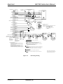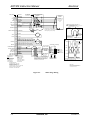
1
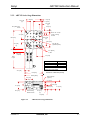
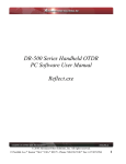
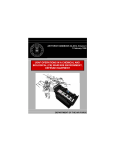
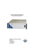
THE ART300 PRECISION
ROTARY STAGE
USER’S MANUAL
P/N: EDA146 (V1.0)
AEROTECH, Inc. • 101 Zeta Drive • Pittsburgh, PA. 15238-2897 • USA
Phone (412) 963-7470 • Fax (412) 963-7459
Product Service: (412) 967-6440; (412) 967-6870 (Fax)
www.aerotech.com
If you should have any questions about the ART and/or comments regarding the documentation, please refer to
Aerotech online at:
http://www.aerotech.com.
For your convenience, a product registration form is available at our web site.
Our web site is continually updated with new product information, free downloadable software, and special pricing
on selected products.
The ART300 Precision Rotary Stage User’s Manual Revision History:
Rev 1.0
© Aerotech, Inc., 2001
March XX, 2001
ART300 Instruction Manual
Table of Contents
TABLE OF CONTENTS
CHAPTER 1:
1.1.
1.2.
1.3.
1.4.
CHAPTER 2:
2.1.
2.2.
CHAPTER 3:
3.1.
3.2.
3.3.
3.4.
CHAPTER 4:
4.1.
4.2.
CHAPTER 5:
5.1.
5.2.
CHAPTER 6:
6.1.
6.2.
CHAPTER 7:
7.1.
7.2.
7.3.
7.4.
OVERVIEW ..................................................................................... 1-1
Introduction ........................................................................................ 1-1
Description ......................................................................................... 1-2
ART300 Model Numbers ................................................................... 1-3
Safety Procedures and Warnings ........................................................ 1-5
SETUP ............................................................................................... 2-1
Installation .......................................................................................... 2-1
2.1.1. Read Instructions.................................................................. 2-1
2.1.2. Unpack Stage ....................................................................... 2-1
2.1.3. Prepare Mounting Surface.................................................... 2-1
2.1.4. Bolt Down Stage .................................................................. 2-1
Stage Dimensions ............................................................................... 2-2
2.2.1. ART310 Series Stage Dimensions ....................................... 2-2
2.2.2. ART315 Series Stage Dimensions ....................................... 2-3
2.2.3. ART320 Series Stage Dimensions ....................................... 2-4
2.2.4. ART330 Series Stage Dimensions ....................................... 2-5
APPLICATION NOTES.................................................................. 3-1
Introduction ........................................................................................ 3-1
Fastening the Application ................................................................... 3-2
Temperature Effects ........................................................................... 3-3
Life Expectancy and Load Capability................................................. 3-4
SPECIFICATIONS .......................................................................... 4-1
Specifications ..................................................................................... 4-1
Motor Information .............................................................................. 4-2
ELECTRICAL.................................................................................. 5-1
Introduction ........................................................................................ 5-1
Stepping Motor Wiring....................................................................... 5-2
VACUUM OPERATION................................................................. 6-1
Introduction ........................................................................................ 6-1
Prep for Vacuum Operation................................................................ 6-2
MAINTENANCE ............................................................................. 7-1
Introduction ........................................................................................ 7-1
Lubrication Schedule.......................................................................... 7-2
Lubrication and Cleaning Process ...................................................... 7-3
Important Notes on Lubrication.......................................................... 7-4
APPENDIX A: WARRANTY AND FIELD SERVICE POLICY.......................... A-1
INDEX
Version 1.0
Aerotech, Inc.
iii
Table of Contents
ART300 Instruction Manual
∇ ∇ ∇
iv
Aerotech, Inc.
Version 1.0
ART300 Instruction Manual
List of Figures
LIST OF FIGURES
Figure 1-1.
ART300 Rotary Stages....................................................................... 1-1
Figure 2-1.
Figure 2-2.
Figure 2-3.
Figure 2-4.
ART310 Series Stage Dimensions...................................................... 2-2
ART315 Series Stage Dimensions...................................................... 2-3
ART320 Series Stage Dimensions...................................................... 2-4
ART330 Series Stage Dimensions...................................................... 2-5
Figure 5-1.
Figure 5-2.
Figure 5-3.
Figure 5-4.
Figure 5-5.
Figure 5-6.
Figure 5-7.
Motor/Stage Wiring............................................................................ 5-2
Motor/Stage Wiring............................................................................ 5-3
Motor/Stage Wiring............................................................................ 5-4
Motor/Stage Wiring............................................................................ 5-5
Limit / Home Wiring Options............................................................. 5-6
Stepping Motor Wiring Options ......................................................... 5-7
Output Interconnecting Cable (SM-O) ............................................... 5-8
∇ ∇ ∇
Version 1.0
Aerotech, Inc.
v
List Of Figures
vi
ART300 Instruction Manual
Aerotech, Inc.
Version 1.0
ART300 Instruction Manual
List of Tables
LIST OF TABLES
Table 1-1.
Table 1-2.
ART300 Model Numbering System (ART310-M-G54-BMS) ........... 1-3
Model Options.................................................................................... 1-3
Table 4-1.
Table 4-2.
Table 4-3.
Table 4-4.
ART300 Series Rotary Stage Specifications ...................................... 4-1
ART310 / ART315 Series Standard Motor Information .................... 4-2
ART320 Series Standard Motor Information ..................................... 4-2
ART330 Series Standard Motor Information ..................................... 4-2
∇ ∇ ∇
Version 1.0
Aerotech, Inc.
vii
List Of Tables
viii
ART300 Instruction Manual
Aerotech, Inc.
Version 1.0
ART300 Instruction Manual
Overview
CHAPTER 1: OVERVIEW
In This Section:
• Introduction ............................................................1–1
• Description .............................................................1–2
• ART300 Model Numbers .......................................1–3
• Safety Procedures and Warnings ............................1–5
1.1.
Introduction
This manual describes technical information needed for typical applications of the
ART300 series translation tables. Included are instructions detailing the entire installation
from unpacking to start-up. Also included are concise explanations concerning
applications, and the maintenance of the mechanical and electrical components. In
addition, there is a section defining the specifications pertinent to the ART300 series
stage from the package.
ART320
ART310
Figure 1-1.
Version 1.0
ART300 Rotary Stages
Aerotech, Inc.
1-1
Overview
ART300 Instruction Manual
1.2.
Description
ART300 Series rotary stages are compact units providing precise positioning capability
for lighter applications. The following is a list of some features:
1-2
•
Maximum rotary speed of 27 rpm, and resolution of 1.5 arc second.
•
Table mounted on dual large diameter pre-loaded angular contact bearings
•
Anti-backlash gearing
•
Base and table are machined from high strength aluminum plate
•
Aluminum surfaces are either clear or black anodized
•
Large aperture versions available
•
Optional right angle brackets for orienting perpendicular to mounting surface
•
Compatibility with a full line of Aerotech positioning and motion controls
•
Standard stage and motor mounted optical home markers
•
DC brushless torque motor comes standard
•
Optional preparation for vacuum operation (10E-6 torr.)
Aerotech, Inc.
Version 1.0
ART300 Instruction Manual
1.3.
Overview
ART300 Model Numbers
The stage model number indicates the optional features on a particular stage. To
determine the options on your stage, refer to Table 1-1. The example given is ART310M-G54-BMS, which designates a 100 mm stage, a metric mounting and grid pattern, a
54:1 gear ratio, and a brushless servo motor.
Table 1-1.
ART3
Series
ART300 Model Numbering System (ART310-M-G54-BMS)
10
Table
Diameter
Stage Construction
Options
10
15
20
30
Table 1-2.
/VAC3
/VAC6
-M
Mounting and
Grid Pattern
-M
-U
-MA
-UA
-G54
Gear
Ratio
-G54
-G108
-G216
-BMS
Motor
Options
-BMS
-BM
-DC
-SM
-NM
-HC
-RB310U
-RB310M
-RB310UA
-RB310MA
-RB315U
-RB315M
-RB315UA
-RB315MA
Model Options
ART300 Series Rotary Stage
ART310
100 mm (4 in) diameter rotary stage
ART315
150 mm (6 in) diameter rotary stage
ART320
200 mm (8 in) diameter rotary stage
ART330
300 mm (12 in) diameter rotary stage
Stage Construction Options
/VAC3
Vacuum preparation of stage to 10-3 torr.
/VAC6
Vacuum preparation of stage to 10-6 torr.
Mounting and Grid Pattern
-M
Tabletop with metric-dimension mounting pattern and holes
-U
Tabletop with English-dimension mounting pattern and holes
-MA
Tabletop with aperture and metric-dimension mounting pattern and holes
-UA
Tabletop with aperture and English-dimension mounting pattern and holes
Gear Ratio
54:1 gear ratio
-G54
ART310, ART315 – Standard
ART320 – Optional
108:1 gear ratio
-G108
ART310, ART315 – Optional
ART320, ART330 – Standard (only ratio available with ART330)
216:1 gear ratio
-G216
ART310, ART315 – Optional
Version 1.0
Aerotech, Inc.
1-3
Overview
Table 1-2.
ART300 Instruction Manual
Model Options – Continued
Motor
-BMS
-BM
-DC
-SM
-NM
Options
-HC
-RB310U
-RB310M
-RB315U
-RB315M
-RB310UA
-RB310MA
-RB315UA
-RB315MA
Accessories
HDZ3
HDZ3M
HDZ4
HDZ4M
Brushless servo motor with connectors and 1000-line encoder. Requires motor-to-controller
cable. ART300, ART315, ART320 (BMS60-A-D25-E1000H/)
Brushless servo motor with connectors and 1000-line encoder. Requires motor-to-controller
cable. ART330 (BM250-MS-E1000H/)
DC servo motor with connectors and 1000-line encoder. Requires motor-to-controller cable.
ART310, ART315 (1035LT-MSOF-E1000LD/)
ART320 (1050LT-MSOF-E1000LD/)
ART330 (1135LT-MSOF-E1000LD/)
Stepping motor with 4.6 m (15 ft) integral cable and home marker pulse (one per rev).
ART310, ART315 (50SMB2-HM/)
ART320 (101SMB2-HM/)
ART330 (310SMB3-HM/)
No motor or encoder
Home cam assembly establishes home reference accurate to one count. Requires home marker
or encoder option on motor.
Raised tabletop for ART310, English
Raised tabletop for ART310, metric
Raised tabletop for ART315, English
Raised tabletop for ART315, metric
Raised tabletop for ART310, English with aperture
Raised tabletop for ART310, metric with aperture
Raised tabletop for ART315, English with aperture
Raised tabletop for ART315, metric with aperture
English right angle L-bracket for ART310, ART315
Metric right angle L-bracket for ART310, ART315
English right angle bracket for ART320, ART330
Metric right angle bracket for ART320, ART330
Listed options may be superseded at any time. Refer to the most recent addition of
the Aerotech Motion Control Product Guide for the most current product
information.
1-4
Aerotech, Inc.
Version 1.0
ART300 Instruction Manual
1.4.
Overview
Safety Procedures and Warnings
The following statements apply throughout this manual. Failure to observe these
precautions could result in serious injury to those performing the procedures and/or
damage to the equipment.
To minimize the possibility of electrical shock and bodily injury, make certain that
all of the electrical power switches are in the off position prior to making any
electrical connections.
DANGER
To minimize the possibility of electrical shock and bodily injury when any electrical
circuit is in use, ensure that no person comes in contact with the circuitry.
DANGER
When this stage is connected to a mechanical system, mechanical motion will occur.
Care must be exercised that all personnel remain clear of any moving parts.
DANGER
To minimize the possibility of bodily injury, make certain that all electrical power
switches are in the off position prior to making any mechanical adjustments.
DANGER
∇ ∇ ∇
Version 1.0
Aerotech, Inc.
1-5
Overview
1-6
ART300 Instruction Manual
Aerotech, Inc.
Version 1.0
Setup
CHAPTER 2:
ART300 Instruction Manual
SETUP
In This Section:
• Installation............................................................2-1
• Stage Dimensions .................................................2-2
2.1.
Installation
This section covers the handling, mounting, and installation of the ART300 series stages.
For added clarity, each step of the installation instructions has been broken down into
component parts. The ART300 series stage should only be installed by those who read
and thoroughly understand this manual. Each step appears below.
2.1.1. Read Instructions
When performing the installation instructions, do not continue to the next step until you
have properly completed the previous step(s).
2.1.2. Unpack Stage
Carefully remove the stage from the protective shipping container. Place the stage on a
smooth, flat, and clean surface. This is a simple, yet very important step in maintaining
the integrity of the stage. You will notice a label that will include a system part number
and serial number. Record these numbers for they contain all the information necessary
to maintain or update system hardware and software. Also, find the enclosed customer
service information and accuracy certification. If it is obvious that damage occurred
during shipping, report it immediately. It is wise to save the shipping container for
possible use in the future.
Improper handling of the stage could adversely affect the performance specifications.
Therefore, use care when moving the stage. Do not allow the stage to drop onto the
mounting surface. Set it down gently.
2.1.3. Prepare Mounting Surface
The mounting surface used with the ART300 series stage should be coplanar within
0.0001 in/in for valid accuracy. For example, if the longest distance between the base hole
pattern is 8 inches, then the mounting surface should be coplanar within 0.0008 inches.
This can be achieved by scraping or shimming the interface until no rocking occurs
beneath the pads of the stage before tightening any of the mounting screws.
2.1.4. Bolt Down Stage
Install and tighten the mounting screws through the mounting holes. See Section 2.2. for
outline drawings and dimensions.
Version 1.0
Aerotech, Inc.
2-1
ART300 Instruction Manual
2.2.
Setup
Stage Dimensions
2.2.1. ART310 Series Stage Dimensions
25.0 [1.00]
63.5 [2.50]
Typ.
9.7 [0.38]
Typ.
M6-1.0 Thd. x 8.6 DP.
[1/4-20 Thd. x 0.34 Dp.]
9 Holes
13.5 [0.50]
63.5 [2.50]
100.0 [4.00]
127.0 [5.00]
Typ.
25.0 [1.00]
Typ.
Ø38.1 [Ø1.50]
(Optional Aperture)
26.9 [1.06]
Ø71 [0.28 Dia.]
4 Holes
38.5 [1.50]
Home Cam
(Optional)
Motor Options
Length
50SMB2-HM
84.3 [3.32]
1035LT-MSOF
158.2 [6.23]
BMS60
132.3 [5.21]
* See motor section for alternate
motors and more details
Motor
Length
Dimensions - Millimeters [Inches]
29.0 [1.14]
37.0 [1.46]
Ø106.1 [Ø4.18]
Raised Tabletop
(Optional)
57.2 [2.25]
Sq.
8.6 [0.34]
59.1 [2.33]
61.0 [2.40]
30.6 [1.20]
48.2 [1.90]
34.8 [1.37]
25.0 [1.00]
Motor Mounting
NEMA 23 Frame
Figure 2-1.
2-2
ART310 Series Stage Dimensions
Aerotech, Inc.
Version 1.0
Setup
ART300 Instruction Manual
2.2.2. ART315 Series Stage Dimensions
125 [5.00]
14.8 [0.54]
25.0 [1.00]
77.4 [3.05]
Typ.
23.6 [0.93]
Typ.
Ø7.1 [Ø0.28] Thru
25.4 [0.97]
3 Holes
12.9 [0.47]
M6-1.0 Thd. x 8.6 Dp.
[1/4-20 x 0.34 Dp.]
75.4 [2.97]
25 Holes
150.9 [5.94]
100.0 [4.00]
Typ.
125.0 [5.00]
Ø 8.1 [Ø1.50]
25.0 [1.00]
(Optional Aperture)
Typ.
26.9 [1.06]
Ø7.1 [Ø0.28]
4 Holes
Home Cam
(Optional)
52.3 [2.03]
Motor
Length
Motor Options
Length
SM (50SMB2-HM)
84.3 [3.32]
DC (1035LT-MSOF) 158.2 [6.23]
BMS (BMS60)
132.3 [5.21]
* See motor section for alternate
motors and more details
38.0 [1.50]
Dimensions - Millimeters [Inches]
152.4 [6.00]
Ø153.9 [Ø6.06]
Raised Tabletop
(Optional)
57.2 [2.25]
Sq.
8.7 [0.34]
50.8 [2.00]
59.1 [2.33]
31.8 [1.25]
30.5 [1.20]
Motor Mounting
NEMA 23 Frame
61.0 [2.40]
10.4 [0.41]
Typ.
22.4 [0.88]
Figure 2-2.
Version 1.0
ART315 Series Stage Dimensions
Aerotech, Inc.
2-3
ART300 Instruction Manual
Setup
2.2.3. ART320 Series Stage Dimensions
M6 Thd. x 7.9 Dp.
6 Holes Eq. Spaced
on a Ø180 B.C.
100.0 [4.00]
25.0 [1.00]
Typ.
127.8 [5.03]
M6-1.0 x 7.9 Dp.
[1/4-20 x 0.31 Dp.]
25 Holes
Ø7.1 [Ø0.28]
3 Holes
25.0 [1.00]
Typ.
Motor
Length
100.0 [4.00]
104.6 [4.12]
Ø38.1 [Ø1.50]
(Optional Aperture)
6.1 [0.24]
Typ.
101.6 [4.00]
117.5 [4.62]
Vertical Mounting Plate
93.7 [3.69]
46.1 [1.81]
7.9 [0.31]
9.5 [0.37]
Typ.
Motor Options
Length
SM (101SMB2-HM)
135.1 [5.32]
DC (1050LT-MSOF)
178.6 [7.03]
BMS (BMS60)
132.3 [5.21]
* See motor section for alternate motors and
more details
Dimensions - Millimeters [Inches]
Ø162.1 [Ø6.38]
Bottom
Mounting
Surface
38.2 [1.50]
57.2 [2.25]
Ø202.2 [Ø7.96]
Motor Mounting
NEMA 23 Frame
Ø7.1 [Ø0.28]
Typ.
Figure 2-3.
2-4
ART320 Series Stage Dimensions
Aerotech, Inc.
Version 1.0
Setup
ART300 Instruction Manual
2.2.4. ART330 Series Stage Dimensions
M6-1.0 Thd. x 10.0 Dp.
[1/4-20 Thd. x 0.38 Dp.]
6 Holes Equally Spaced
on a 250.0 [10.00] B.C.
228.6 [9.00]
158.8 [6.25]
1/4-20 Thd. x 0.38 Dp.
4 Holes
114.3 [4.50]
50.8 [2.00]
7.1 [0.28]
Typ.
M6-1.0 Thd. x 10.0 Dp.
[1/4-20 Thd. x 0.38 Dp.]
25 Holes
38.9 [1.53]
9.7 [0.38]
Typ.
Ø304.8 [Ø12.00]
50.8 [2.00]
139.7 [5.50]
228.6 [9.00]
228.6 [9.00]
247.7 [9.75]
254.0 [10.00]
25.0 [1.00]
Typ.
140.2 [5.52]
1/4-20 Thd. x 0.38 Dp.
4 Holes
M6-1.0 Thd. x 10.0 Dp.
6 Holes Equally Spaced
on a 190mm B.C.
Ø7.1 [Ø0.28] Thru
4 Holes as Shown
Ø85.7[Ø3.38]
(Optional Aperture)
Motor
Length
25.0 [1.00]
Typ.
50.8 [2.00]
64.3 [2.53]
Top Mounting
Surface
Home Cam
(Optional)
Motor Mounting
[NEMA 34 Frame]
Vertical Mounting
Surface
11.9 [0.47]
88.9 [3.50]
127.0 [5.00]
15.9 [0.62]
Typ.
Figure 2-4.
Dimensions - Millimeters [Inches]
14.4 [0.56]
Typ.
93.6 [3.69]
Ø235.0 [Ø9.25]
Motor Options
Length
SM (310SMB3-HM)
165.4 [6.51]
DC (1135LT-MSOF)
202.7 [7.98]
BMS (BMS250)
190.0 [7.48]
* See motor section for alternate motors
and more details
Bottom Mounting
Surface
ART330 Series Stage Dimensions
∇ ∇ ∇
Version 1.0
Aerotech, Inc.
2-5
ART300 Instruction Manual
2-6
Aerotech, Inc.
Setup
Version 1.0
ART300 Instruction Manual
Application Notes
CHAPTER 3: APPLICATION NOTES
In This Section:
• Introduction .....................................................................3-1
• Fastening the Application ................................................3-2
• Life Expectancy and Load Capability..............................3-4
3.1.
Introduction
When the stage is secure, the motor drive can be installed per the directions in Chapter 5.
After becoming comfortable with the drive electronics, verify that the maximum speed is
obtainable without encountering any fault conditions (i.e., loss of steps with the stepper
motor assembly). Do this before any delicate payloads are attached. Document all results.
Version 1.0
Aerotech, Inc.
3-1
Application Notes
3.2.
ART300 Instruction Manual
Fastening the Application
When fastening the payload to the upper mounting surface, the mounting interface should
be coplanar within 0.00001 in/in for valid accuracies. It is recommended that feet or pads
be used on the mounting surface to minimize the amount of surface needed to be
coplanar.
3-2
Aerotech, Inc.
Version 1.0
ART300 Instruction Manual
3.3.
Application Notes
Temperature Effects
The permissible ambient temperature operating range of the stage assembly is 32°F to
140°F (in a non-condensing atmosphere). Due to thermal expansion or contraction, the
geometry of the stage will vary slightly with temperature.
Version 1.0
Aerotech, Inc.
3-3
Application Notes
ART300 Instruction Manual
3.4.
Life Expectancy and Load Capability
The accuracy specification of ART300 series stages is measured at the center of travel
1.75 inches above the table with the stage in a horizontal position.
It is recommended that application loads be symmetrically distributed (i.e., the payload
should be centered on the stage table and the entire stage should be centered on the
support structure). If cantilevered loads are to be applied, consult the factory for the load
capability.
Be sure to consider dynamic loading when using the stage for high-speed applications
(especially with cantilever loading).
∇ ∇ ∇
3-4
Aerotech, Inc.
Version 1.0
Specifications
CHAPTER 4:
ART300 Instruction Manual
SPECIFICATIONS
In This Section:
• Specifications ................................................................... 4-1
• Motor Information............................................................ 4-2
4.1.
Specifications
Table 4-1.
ART300 Series Rotary Stage Specifications
Basic Model
Table Diameter
Total Travel
ART310
100 mm (4 in)
Drive System
54:1
108:1
216:1
54:1
Maximum Speed 108:1
216:1
Accuracy
Repeatability (Unidirectional)
Axis Wobble
Radial
Axis Runout (1)
Axial
Resolution
Axial
Maximum Load
Radial
Nominal Stage
Weight
Output Torque
(static)
w/o Motor
w/ Motor
Material
Stage and Table
Stage
Finish
Table
1.
ART315
ART320
ART300
150 mm (6 in)
200 mm (8 in)
300 mm (12 in)
360° continuous, both azimuth and elevation
Precision Worm Gear
Precision Worm Gear in Oil Bath
(54:1 motor-to-table ratio standard) (108:1 motor-to-table ratio standard)
6 arc sec @ 4000 steps/rev motor resolution
N/A
3 arc sec @ 4,000 steps/rev motor resolution
1.5 arc sec @ 4,000 steps/rev motor resolution
N/A
11 rpm
27 rpm
N/A
5.5 rpm
27 rpm
32 rpm
2.75 rpm
13.5 rpm
N/A
3 arc min
1.0 arc min
0.5 arc min
12 arc sec
6 arc sec
20 arc sec
10 arc sec
5 arc sec
15.0 P LQ
P LQ
P LQ
115.0 kg
25.0 kg (55.1 lb)
45.0 kg (99.2 lb)
(253.5 lb)
90.0 kg
10.0 kg (22.0 lb)
25.0 kg (55.1 lb)
(198.4 lb)
0.7 kg-m
4.6 kg-m
0.3 kg-m (25 lb-in)
(60 lb-in)
(400 lb-in)
2.0 kg (4.46 lb)
2.9 kg (6.4 lb)
6.4 kg (14.1 lb) 14.3 kg (31.5 lb)
3.1 kg (6.8 lb)
4.0 kg (8.8 lb)
7.5 kg (16.5 lb) 17.9 kg (39.5 lb)
Stage: Cast aluminum; Table:
Aluminum
Aluminum
Paint: Textured Epoxy (Polane-T);
Black Anodize
Pebble Gray Color
Hard Coating (62 Rockwell Hardness Teflon Impregnated)
Measured 75 mm (3 in) above table; includes wobble and eccentricity components.
Version 1.0
Aerotech, Inc.
4-1
ART300 Instruction Manual
4.2.
Table 4-2.
Specifications
Motor Information
ART310 / ART315 Series Standard Motor Information
Code
Type
-BMS
(Default)
Brushless
Servo
Model
Bus
Amps
Cable
BMCHPD/BFCD
-DC
-SM
DC Servo
BMS60-A- Up to 160
D25-E1000H
VDC
1035LTMSOFE1000LD
Microstepping 50SMB2-HM
up to 1.8 Arms Cont
up to 7.3 Arms Peak
PMCHPD/BFCD
PMCHPD/BFCD
BMP2HPD/BFCD
DC-MSO
40 VDC
up to 4.1 A Cont
up to 8.2 A Peak
40 VDC
up to 1 A
BADC-MSO1
BADC-MSO1
DCC
SMS-O
SMC
Table 4-3.
ART320 Series Standard Motor Information
Code
Type
-BMS
(Default)
Brushless
Servo
Model
Bus
Amps
Cable
BMCHPD/BFCD
BMS60-A- Up to 160
D25-E1000H
VDC
-DC
DC Servo
1050LTMSOFE1000LD
-SM
Microstepping
101SMB2HM
Table 4-4.
Driver
U511/DR500/
DR600
BB501 + BA
BAI
U100Z
U511/DR500/
DR600
BB501 + BA
BAI
U100S
U511/DR500/D
R600
U100M
up to 1.8 Arms Cont
up to 7.3 Arms Peak
PMCHPD/BFCD
PMCHPD/BFCD
BMP2HPD/BFCD
DC-MSO
40 VDC
up to 5.4 A Cont
up to 10.8 A Peak
40 VDC
up to 5 A
BADC-MSO1
BADC-MSO1
DCC
SMS-O
SMC
Driver
U511/DR500/
DR600
BB501 + BA
BAI
U100Z
U511/DR500/
DR600
BB501 + BA
BAI
U100S
U511/DR500/D
R600
U100M
ART330 Series Standard Motor Information
Code
Type
Model
-BM
(Default)
Brushless
Servo
BM250E
-DC
DC Servo
1135LTMSOFE1000LD
-SM
Microstepping
310SMB3HM
Bus
Amps
Cable
Driver
BMC2/BFC U511/DR500/DR600
Up to 320 up to 7.1 Arms Cont
PMC/BFC
BB501 + BA
VDC
up to 17.8 Arms Peak
PMC/BFC
BAI
BMP2/BFC
U100Z
DC-MSO
U511/DR500/DR600
up to 5.5 A Cont
BADC-MSO1
BB501 + BA
80 VDC
up to 11.0 A Peak BADC-MSO1
BAI
DCC
U100S
SMS-O
U511/DR500/DR600
80 VDC
up to 6 A
SMC
U100M
∇ ∇ ∇
4-2
Aerotech, Inc.
Version 1.0
Electrical
CHAPTER 5:
ART300 Instruction Manual
ELECTRICAL
In This Section:
• Introduction ..................................................................... 5-1
• Stepping Motor Wiring .................................................... 5-2
5.1.
Introduction
Aerotech ART300 series rotary translation stages can be supplied with a full line of
Aerotech positioning and motion controls.
When the ART300series stage is part of an Aerotech system refer to the system manuals
and documentation for additional installation and operation information. All systems are
adjusted for optimum performance. The end user need only connect the interconnecting
cable from the drive chassis to the stage, and apply power.
Never connect or disconnect any electrical component or interconnecting cable while
power is applied. Serious damage will result.
WARNING
Version 1.0
Aerotech, Inc.
5-1
ART300 Instruction Manual
5.2.
Electrical
Stepping Motor Wiring
For stages equipped with standard Aerotech stepping motor configurations, please refer to
the following Figures.
MSOI, MSOF
No connector at
J1, solder wires to
P.C. Board
MO, MOF
COS E 25
COS-N
K 19
SIN F 26
#22 WHT / RED
6
#22 WHT / YEL
7
#22 WHT / GRN
SIN-N L 20
#22 BRN
COM B 32
+V A 35
MARKER
G 21
MARKER-N
M 22
C 30
- Z 34
J1
5
#22 WHT / ORN
8
1
12
R5
14
R6
16
R7
R8
18
11 13 15 17
2
#22 WHT / GRY
4
#22 WHT / BRN
#16 GRN/YEL
WHT/BLU
6
BLU
7
YEL
8
WHT/YEL
BLK
R4
2
RED
R3
4
ORN
DATAMETRIC
K30M
Sine Wave
Output Encoder
On 640B1207
R4 = 120V
R5 - R8 = 1K
Delete R3
Delete Jumpers:
11-12, 13-14,
15-16, 17-18
3
3
Connector - Connect if
P Pin
interfacing to switching
S amps.
5
1
R1120V
R2 120V
#22 YEL
Standard Color Code Shown.
Due to encoder variations, wire colors
may be interchanged to get proper
phasing.
Encoder Terminal Card
690B1207
Connect To
Frame
#22 WHT
DATAMETRIC
K30M
Square Wave
Output Encoder
TACH
6
#16 RED
H 5
#16 RED
P 6
#16 RED
CW + J 16
#16 BLK
V 10
#16 BLK
CW - Q 17
#16 BLK
U 11
D 18
+5V W 37
COM X 31
CW LIMIT-N
R 27
CCW LIMIT-N
S 28
HOME LIMIT-N
T 14
(M Only - 1210 & Larger Motors)
1
(MO, MSO-I - 1210 & Lgr Motors)
2
(MO, MSO-I - All Motors)
Delete R3
Add Jumpers:
11-12, 17-18
4
MOTOR
Delete Jumpers:
13-14, 15-16
690B1207
(MO, MSO-I - 1210 & Lgr Motors)
2
4
3
690B1207
BLU
WHT
ORN
BLK
VIO
GRN
RED
RED / BLK
WHT / BLK
Trump Ross
Encoder
Sine Wave
Output Encoder
On 640B1207
R3, R4 = 120V
R5 - R8 = 1K
Delete R1, R2
Delete Jumpers:
11-12, 13-14,
15-16, 17-18
Depending on signal phase relationship from encoder jumpers may
be different than shown.
(MO, MSO-I - All Motors)
(MO - 1210 & Larger Motors)
#22 G/YEL
#22 VIO
#22 GRN
#22 WHT
#22 GRY
#22 PINK
Recept MS3102A-24
Insert MS24-28P
Bulkhead 206151-1
Pins (16-18) 66098-7
Pins (20-24) 66102-7
MATE
Str. Plug MS3106A-24
Angle Plug (Optional)
MS3108A or B-24
Insert MS24-285
Clamp AN3057016
MATE
Recept 206150-1
Sockets (16-18) 66100-7
Sockets (20-24) 66104-7
Clamp 206138-1
6.For 1035 & 1050 Motor see ES11217
5.Standard wiring shown with solid line Optional wiring dotted
4.CW Limit stops CW rotation
3.Rotational reference is looking into flange of motor.
2.Wiring phase applies when the encoder is mounted
On the rear of the motor tach assembly.
1.Wiring is the same for “x” and “y” axis.
Small Stage Limit Wiring
Amp. Plug 640234-6
Contacts 640230-1
6
J2 P2
6 6
2
2
2
1
1
1
1
3
3
3
3
6
4
4
4
5
5
5
Optional
Connect
5
Optional Optical
Limit Switch
Marker
COS
Opt. Con
+5V
6
2
1
3
4
3
2
1
2
1
5
When 300 series stgs
are used, wiring to J1-5
& J1-6 must be
interchanged.
690B1270
Add jumper if no separate Home
Limit Switch is employed &
ES11161 is implemented on the
system drive card SL or PL.
Jumper 4-5 is needed for standard
CCW Home.
Jumper 3-5 is needed for optional
CW Home
SCKTS
1
2
3
03-06-1032
Sockets
02-06-1132
3
2
1
2
1
PINS
1
2
3
CW Limit
CCW Limit
Home Lmt
(CAM Switch)
NOTES ON ENCODER OUTPUTS:
A.Both SIN and Square Wave encoder outputs are designed to
input to a differential amplifier for noise immunity.
B.Note to Customer: The units you receive will be properly
phased. On account of C & D below, the color codes of the
encoder wiring output may be different from the color shown on
the drawing.
C.Square Wave Encoders have SIN, SIN-N Bias, COS-N, COS
Bias, Marker, and Marker-N Bias outputs. Encoder wire colors
may be interchanged (SIN-N, SIN Bias or COS, COS-N Bias) to
obtain proper phasing.
D.SIN Wave encoders have SIN, SIN-N, COS, COS-N outputs.
Encoder wire colors may be interchanged (SIN-N, SIN, or COS-N,
COS) to get proper phasing. Marker and Marker-N are also
Output.
03-06-2032
Pins
02-06-2132
SIN
630C1066
Motor/Stage Wiring & Assembly
DC Encoded Drives
(MO, MOF, MSO-I, MSO-F)
Figure 5-1.
5-2
On 640B1207
R4 - R8 = 120V
7
SCKTS
PINS
+ Y 29
#22 BLU
5
6
7
8
1
Motor/Stage Wiring
Aerotech, Inc.
Version 1.0
Electrical
MSOI, MSOF
COS E 25
COS-N K 19
ART300 Instruction Manual
MARKER G 21
MARKER-N M 22
R5 12
5
#22 W / ORN
#22 YEL
Encoder Terminal Card
690B1207
J1
#22 W / RED
#22 W / YEL
SIN F 26
#22 W / GRN
SIN-N L 20
#22 BRN
COM B 32
+V A 35
No connector at
J1, solder wires to
P.C. Board
MO, MOF
R6
6
R8
8
1
JP1
18
C1
.47uf
R2 220V
WHT/BLU
6
BLU
7
YEL
8
WHT/YEL
BLK
2
11 13 15 17
4
#22 W / BRN
5
1
R1 220V
2
#22 W / GRY
16
R7
7
JP1 installed as standard.
Remove as required.
14
3
120V R4
4
R3
3
ORN
7
Trimpots are Factory
Set and Locked
#16 GRN/YEL
Standard Color Code Shown.
6 Due to encoder variations, wire colors may be
interchanged to get proper phasing.
To Brd Mtg
Standoff
7
TACH - Z 34
RED
Delete
Delete Jumpers:
11-12, 13-14, ,15-16, 17-18
SIGNAL SHIELD C 30
6
Encoder Signal and Electrical Specs.
CW Motor Rotation
See Note 1
TACH
(optional)
#22 WHT
+2V (Typ)
COS
TACH+ Y 29
#22 BLU
#16 RED
MOTOR + P 6
#16 RED
MOTOR + J 16
+2V p-p
SIN-N
RED
#16 BLK
MOTOR - V 10
#16 BLK
MOTOR - Q 17
MATE
Str. Plug MS3106A-24
Insert MS24-285
Clamp AN3057016
MOTOR -
+3.5V
0V
+2.5V Bias
0V
Marker
Marker-N
Splice
BLK
To Brd Mtg Standoff
Bulkhead 206151-1
Pins (16-18) 66098-7
Pins (20-24) 66102-7
6
J2
6
2
Optional Connection to Frame
VIO
2
1
3
1
3
4
5
4
5
GRN
WHT
no
GRY
PINK
no
no
3
ORN nc
BLU
YEL
3
Form A
Limit Wiring
(Standard)
690B1270
MATE
Recept 206150-1
Sockets (16-18) 66100-7
Sockets (20-24) 66104-7
Clamp 206138-1
Assembly Drawing Reference
23 Frame Size (1017, 1035, 1050)
MO, MSOI: 041C01-1700 (w/ Tach), 041C01-1000 (w/o Tach)
MOF, MSOF: 035C01-1800 (w/ Tach), 035C01-1400 (w/o Tach)
34 Frame Size (1075, 1135)
MO, MSOI: 041D01-1800 (w/ Tach), 041D01-1100 (w/o Tach)
MOF, MSOF: 075D01-1800 (w/ Tach), 075D01-1500 (w/o Tach)
42 & Larger Frame Size (1210, 1410, 1580, 1960)
MO, MSOI: 041D01-1900-2 (w/ Tach), 041D01-1900-1 (w/o Tach)
MOF, MSOF: 075D01-1800 (w/ Tach), 075D01-1500 (w/o Tach)
3
nc
nc
WHT 5
GRY 5
3
1 1
3 3
6 5
VIO
Optical Limit
Switch
GRN
400, 500, 3000 Srs.
Jumper 4-5, 6-7
Remove 3-4, 7-8
ORN 5
BLU 5
5 6
3
Form B
Limit Wiring
(Optional)
1 1
3 3
4 2
Optical Limit
Switch
400, 500, 3000 Srs.
Jumper 4-5, 6-7
Remove 3-4, 7-8
2 4
3
Reversed
4
Standard
Reversed
4
Standard
Optical LMT SW Wiring
Active Lo Outputs
(Standard)
1
Motor Rotational Reference
CW/CCW rotation is viewed from the flange end of the motor
2
Limits
CW & CW-N signal indicates over travel in the clockwise direction
CCW & CCW-N signal indicates over travel in the counter clockwise direction
5V TTL logic output and dry contact switch closure shown.
Most Aerotech controls are standardly configured to accept active low limits with
active high limits or “Form B” being optional.
Reference applicable system manual or system print.
3
Home Limit
All Aerotech controls are configured to accept a home limit input for generating a cold
starting reference point.
This input may come from an independent switch (cam sw on rotary stage) or may be
paralleled form the CCW (Standard) or CW (optional) limit sw (on linear stages).
4
Reversed Limit Wiring
Reverse limit switch wiring is used for 300 series open frame stages.
5
Wire Color
Wire colors are reversed with 200 series stages that incorporate a foldback motor
(FM) option.
Figure 5-2.
Version 1.0
+
5VDC +/- 5%
150mA
Flat 0 to 25 kHz, 6db octave roll-off above 25 kHz
Cos, Cos-N, Sin, Sin-N - RV3430A
Min Load R = 500V to common
MKR, MKR-N - LM393D, Open Coll.
with ≈ 4 KV pull-up, Max Sink = 4.0 mA,
Max Source = 0.5 mA
#16 G/YEL
#22 G/YEL
D 18
#22 VIO
+5V W 37
#22 GRN
COM X 31
#22 WHT
CW LIMIT-N, CW LIMIT R 27
#22 GRY
CCW LIMIT-N, CCW LIMIT S 28
#22 PINK
HOME LIMIT-N, HOME LIMIT T 14
Recept MS3102A-24
Insert MS24-28P
Supply Voltage:
Supply Current:
Freq. Response:
Output Device:
COS-N
SIN
Frame GND N 1
Amplified
Sinewave
Encoder
Optical LMT SW Wiring
Active Hi Outputs
(Optional)
Drawing: 630C166-1 (Motor/Stage Wiring &
Assy DC Encoded Drives – MO, MOF, MSOF,
MSOI Using SineWave Output Encoders)
Motor/Stage Wiring
Aerotech, Inc.
5-3
ART300 Instruction Manual
COS E 25
COS-N
SIN
SIN-N
ENC. COM
No connector at
J1, solder wires
to P.C. Board
MO, MOF
K
F
L
B
19
26
20
32
#22 w/ RED
#22 w/ ORN
#22 w/ YEL
#22 w/ GRN
#22 BRN
Pin Connector - Connect if
interfacing to switching
amps.
ENC. +5V A 35 #22 YEL
#22 w/ GRY
MARKER G 21
#22 w/ BRN
MARKER-N M 22
SIGNAL SHIELD C 30
TACH - Z 34
TACH + Y 29
#16 GRN/YEL
#22 WHT
J1
5
6
7
8
1
P
S
#22 G/YEL
MSOI, MSOF
Electrical
Encoder Terminal Card
690B1207
R6 120 V
DATAMETRIC
Square Wave
Encoder
5
R5 120 V 12
6
14
R7 120 V
R8 120 V
Model #:
K3DM-XXXX-5CO-6B
(xxxx = line count)
7
16
8
18
Output Device is
74S04
1
R1 F.S.
R2 F.S.
11 13 15 17 R4
120 V
R3
120 V
2
4
3
2
3 ENCODER TERMINAL CARD SET-UP
1). Delete jumpers 11-12, 13-14, 15-16, 17-18
2). Delete resistors R1 & R2
3). R3 through R8 = 120V, 1/4 W
4
3
Standard Color Code Shown. Due to
Encoder variations, wire colors may be
interchanged to get proper phasing.
Connect To
Frame
TACH
–
1
2
The trimpots are factory
set and glyptolled. They
ordinarily should not
require re-adjustment
#22 BLU
MOTOR SHIELD
LIMIT +5V
LIMIT COM
CW LIMIT-N
V
Q
U
V
CCW LIMIT-N Q
HOME LIMIT-N U
Recept MS3102A-24
Insert MS24-28P
MATE
Str. Plug MS3106A-24
Angle Plug (Optional)
MS3108A or B-24
Insert MS24-285
Clamp AN3057016
Bulkhead 206151-1
Pins (16-18) 66098-7
Pins (20-24) 66102-7
MATE
Recept 206150-1
Sockets (16-18) 66100-7
Sockets (20-24) 66104-7
Clamp 206138-1
SIN, SIN-N, Duty Cycle
Trimpot
+3.2V
COS-N
0V
Small Stage Limit Wiring
P2
6
2
1
3
Amp. Plug 640234-6
Contacts 640230-1
Optional
Connect
4
5
1
3
6
5
Optional Optical
LMT Switch
690-1090 thru
690-1095
5
When 300 stgs are
used, wiring to J1-5
J1 & J1-6 must be
interchanged.
690B1270
6
2
1
3
4
Add jumper if no separate Home Limit Switch
is employed & ES11161 is implemented on the
system drive card SL or PL. Jumper 4-5 is
needed for standard CCW Home. Jumper 3-5
is needed for optional CW Home
Opt. Con
+5V
3
2
1
2
1
3
2
1
2
1
PINS
SCKTS
1
1
2
2
3
3
03-06-1032 03-06-2032
Sockets
Pins
02-06-1132 02-06-2132
Assembly Drawing Ref.
Small Motors (1017, 1035, 1050)
MO, MSOI - See ES11217
MOF, MSOF - See 035C01-1800
Large Motors (1075, 1135, 1410, 1580, 1960):
MO, MOSI - See Motor Outline DWG.
MOF, MSOF - See 075D01-1800
COS
SIN
CW Limit
CCW Limit
Home Lmt
(CAM Switch)
SIN-N
Marker-N
Marker
Waveforms: CW Rotational reference is looking into
motor flange. Output Device is 74S04.
630C1066-2
Motor / Stage Wiring & Assembly: DC Encoded
Drives (MO, MOF, MSOF Using Datametric
#K3DM-XXX-5C0-6B Encoder)
Figure 5-3.
5-4
Marker,
Marker-N
Pulsewidth
Trimpot
1 ENCODER SIGNAL DEFINITION
CW
SCKTS
PINS
#16 BLK (MO, MOF, MSOI, MSOF - 1210 & Lgr Motors)
10
#16 BLK (MO, MOF, MSOI, MSOF - All Motors)
17
#16 BLK (MO, MOF Only - 1210 & Larger Motors)
11
#16 G/YEL
To Frame
1
J2
#22 G/YEL
6
18
6
#22 VIO
2
37
2
#22 GRN
1
1
31
#22 WHT
3
3
27
#22 GRY
4
4
28
#22
PINK
5
5
14
COS, COS-N
Duty Cycle
Trimpot
+
#16 RED (MO, MOF Only - 1210 & Larger Motors)
H 5
#16 RED (MO, MOF, MSOI, MSOF - 1210 & Lgr Motors)
P 6
#16 RED (MO, MOF, MSOI, MSOF - All Motors)
+ MOTOR –
MOTOR + J 16
V
MOTOR - Q
U
FRAME GROUND N
2 TRIMPOT
DEFINITION
Motor/Stage Wiring
Aerotech, Inc.
Version 1.0
Electrical
MSOI, MSOF
COS E 25
COS-N K 19
ART300 Instruction Manual
MARKER G 21
MARKER-N M 22
SIGNAL SHIELD C 30
0V R5 12
5
#22 W / ORN
#22 YEL
Encoder Terminal Card
690B1207
J1
#22 W / RED
#22 W / YEL
SIN F 26
#22 W / GRN
SIN-N L 20
#22 BRN
ENC COM B 32
ENC +5V A 35
No connector at
J1, solder wires to
P.C. Board
MO, MOF
0V R6
6
0V R7
7
JP1 installed as standard.
Remove as required.
7
16
JP1
R1
C1
.47uf
R2
2
11 13 15 17
4
#22 W / BRN
3
0V R4
4
0V R3
3
Delete R1, R2
Delete Jumpers:
11-12, 13-14, ,15-16, 17-18
To Brd Mtg
Standoff
#16 GRN/YEL
6
7
Standard Color Code Shown.
6 Due to encoder variations, wire colors may be
interchanged to get proper phasing.
7
TACH - Z 34
Renco #R8023D_____-3/8-H-5-LD-S
or
LEDEX #K3DM_____-5LD-6B
or
Equivalent
8
18
1
2
#22 W / GRY
6
0V R8
8
1
Amplified
Sinewave
Encoder
5
14
Encoder Signal and Electrical Specs.
CW Motor Rotation
See Note 1
TACH
(optional)
#22 WHT
COS
TACH+ Y 29
#22 BLU
Supply Voltage: 5VDC +/- 5%
Supply Current: 150mA
Freq. Response: Cos, Sin = 75 kHz
Marker = 20 kHz
Output Device: Texas Inst. Line Driver #75158 or Motorola #MC3487
Sink = 40 mA
Source = 40 mA
COS-N
SIN
#16 RED
MOTOR + P 6
#16 RED
MOTOR + J 16
SIN-N
RED
#16 BLK
MOTOR - V 10
#16 BLK
MOTOR - Q 17
Frame GND N 1
MATE
Str. Plug MS3106A-24
Insert MS24-285
Clamp AN3057016
Marker
Marker-N
Splice
BLK
To Brd Mtg Standoff
Bulkhead 206151-1
Pins (16-18) 66098-7
Pins (20-24) 66102-7
6
2
1
3
4
5
J2
6
Optional Connection to Frame
VIO
2
1
3
4
5
GRN
WHT
no
GRY
PINK
no
no
3
690B1270
MATE
Recept 206150-1
Sockets (16-18) 66100-7
Sockets (20-24) 66104-7
Clamp 206138-1
ORN nc
BLU
YEL
3
Form A
Limit Wiring
(Standard)
Terminal Strip
Assembly Drawing Reference
23 Frame Size (1017, 1035, 1050)
MO, MSOI: 041C01-1700 (w/ Tach), 041C01-1000 (w/o Tach)
MOF, MSOF: 035C01-1800 (w/ Tach), 035C01-1400 (w/o Tach)
34 Frame Size (1075, 1135)
MO, MSOI: 041D01-1800 (w/ Tach), 041D01-1100 (w/o Tach)
MOF, MSOF: 075D01-1800 (w/ Tach), 075D01-1500 (w/o Tach)
42 & Larger Frame Size (1210, 1410, 1580, 1960)
MO, MSOI: 041D01-1900-2 (w/ Tach), 041D01-1900-1 (w/o Tach)
MOF, MSOF: 075D01-1800 (w/ Tach), 075D01-1500 (w/o Tach)
3
nc
nc
WHT 5
GRY 5
3
1 1
3 3
6 5
VIO
Optical Limit
Switch
GRN
400, 500, 3000 Srs.
Jumper 4-5, 6-7
Remove 3-4, 7-8
ORN 5
BLU 5
5 6
3
Form B
Limit Wiring
(Optional)
1 1
3 3
4 2
Optical Limit
Switch
400, 500, 3000 Srs.
Jumper 4-5, 6-7
Remove 3-4, 7-8
2 4
3
Reversed
4
Standard
Reversed
4
Standard
Optical LMT SW Wiring
Active Lo Outputs
(Standard)
1
Motor Rotational Reference
CW/CCW rotation is viewed from the flange end of the motor.
2
Limits
CW & CW-N signal indicates over travel in the clockwise direction
CCW & CCW-N signal indicates over travel in the counter clockwise direction
5V TTL logic output and dry contact switch closure shown.
Most Aerotech controls are standardly configured to accept active low limits with
active high limits or “Form B” being optional.
Reference applicable system manual or system print.
3
Home Limit
All Aerotech controls are configured to accept a home limit input for generating a cold
starting reference point.
This input may come from an independent switch (cam sw on rotary stage) or may be
paralleled form the CCW (Standard) or CW (optional) limit sw (on linear stages).
4
Reversed Limit Wiring
Reverse limit switch wiring is used for 300 series open frame stages.
5
Wire Color
Wire colors are reversed with 200 series stages that incorporate a foldback motor
(FM) option.
Figure 5-4.
Version 1.0
MOTOR -
#16 G/YEL
#22 G/YEL
D 18
#22 VIO
+5V W 37
#22 GRN
COM X 31
#22 WHT
CW LIMIT-N, CW LIMIT R 27
#22 GRY
CCW LIMIT-N, CCW LIMIT S 28
#22 PINK
HOME LIMIT-N, HOME LIMIT T 14
Recept MS3102A-24
Insert MS24-28P
+
Optical LMT SW Wiring
Active Hi Outputs
(Optional)
Drawing: 630C166-3 (Motor/Stage Wiring &
Assy DC Encoded Drives – MO, MOF, MSOF,
MSOI Using SineWave Output Encoders)
Motor/Stage Wiring
Aerotech, Inc.
5-5
ART300 Instruction Manual
Electrical
CAM SWITCH or MICRO SWITCH WIRING
OPTICAL HOME WIRING
Sockets
J1
J1
Pins
37
31
14
15
#22 GRN
COMMON
#22 PINK
Home LMT N.O.
#22 YEL
Home LMT N.C.
1
1
31
2
2
22
3
21
3
#22 VIO
OPTICAL
HOME BOARD
690-1098
+V
#22 GRN
COM
#22 W/BRN
7
#22 GRN/YEL
7
MARKER-N
MARKER
3
3
4
OPTICAL LIMIT WIRING (For stages using optical limit switch)
J1
SMALL STAGE LIMIT WIRING (Optional)
J1
31
27
Pins
#22 GRN
COMMON
#22 WHT
CW LMT N.O.
3
23
2
28
1
14
H. LMT
6
4
Optional
CW LMT
15
14 H. LMT N
If 200 Series Stage w/
Foldback Motor Option (FM)
Wire Colors For CW & CCW
Limtis Are Switched.
CCW LMT
1
3
6
4
OPTICAL LIMIT SWITCH
If applicable:
Jump 4-5, 6-7
Remove 3-4, 7-8
5
2
6
Wires 2 & 5 are switched
with 4 & 6 with open
frame 300 Series stages
or 200 Series stages with
foldback motors (FM).
3
STEPPING MOTOR LIMIT WIRING (No Stage) (Optional)
3
J1
SMALL STAGE LIMIT WIRING (Standard)
31
J1
31
#22 ORN
#22 BLU
1
H. LMT N.O.
#22 PINK
+5V
COMMON
CW LMT N
#22 GRY CCW LMT N
24
CCW LMT N.O.
#22 VIO
#22 GRN
#22 WHT
PINK
#22 GRY
3
2
YEL
28
37
31
27
Sockets
#22 GRN
COMMON
#22 ORN
CW LMT N.C.
23
COMMON
27 #22 WHT
3
3
4
4
28
Sockets
36”
#22 GRN
#22 GRY
3
CW LMT N.O. / N.C.
2
CCW LMT N.O. / N.C.
1
Optional
4
H. LMT N.O.
#22 WHT
CW LMT N.O.
27
2
2
5
5
6
14 #22 PINK
FORM A (N.O.)
or
FORM B (N.C.)
Form A is standard when
interfacing to an Aerotech Drive.
3
24
28
#22 BLU
CCW LMT N.C.
#22 GRY
CCW LMT N.O.
H. LMT N.O.
14
15
#22 PINK
#22 YEL /
H. LMT N.C.
STANDARD MOTOR LIMIT WIRING (No Stage) (Standard)
J1
1
1
#22 VIO
+5V
COMMON
CW LMT N.C.
37
#22 GRN
31
#22 WHT.
23
6
4
Optional
If 200 Series Stage w/
Foldback Motor Option (FM)
Wire Colors For CW & CCW
Limtis Are Switched.
27
24
3
28
#22 ORN
CW LMT N.O/N.C.
#22 GRY
CCW LMT N.C.
#22 BLU
CCW LMT N.O./N.C.
H. LMT N.O.
#22 PINK
14
#22 YEL
15
6
H. LMT N.C.
3
IT IS STANDARD TO TIE THE MOTOR SHIELD CONNECTION
TO THE MOTOR FRAME AND LEAVE THE SIGNAL SHIELD
CONNECTION FLOATING. THIS PHILOSOPHY MAY BE
VARIED AS REQUIRED.
J1 CONSISTS OF THE FOLLOWING:
3
A) AMP PLUG #206151-2
B) AMP EXTENDER #207055-1 (OPTIONAL)
C) AMP CLAMP #206138-1
D) AMP #16 PINS #66098-7
E) AMP #22 PINS #66102-7
MATE TO J1 CONSISTS OF:
A) AMP RECEPTACLE #206150-1
B) AMP CLAMP #206138-1
C) AMP #16 SOCKETS #66100-7
D) AMP #22 SOCKETS #66104-7
2
4
03-06-1032
SOCKETS
02-06-1132
1
2
3
03-06-2032
PINS
02-06-2132
SOCKETS
5
6
1
2
3
PINS
MOLEX CONNECTOR DEFINITION:
03-06-1061 3 6
SOCKETS 2 5
02-06-1132
1 4
03-06-2062 1 4
PINS
2 5
02-06-2132
3 6
SOCKETS
Figure 5-5.
5-6
MOLEX CONNECTOR DEFINITION:
PINS
7
6
3
4
If needed for Optical Limit
2
5
1
FORM C
FORM A (N.O.)
or
FORM B (N.C.)
Form A is standard when
interfacing to an Aerotech
Drive.
STANDARD ARRANGEMENT FOR HOME LIMIT WIRING IS TO
PARALLEL THE CCW LIMITS. IF CW HOME IS REQUIRED,
THE CW LIMITS SHOULD BE WIRED IN PARALLEL INSTEAD.
ON STAGES/MOTORS SHIPPED PRIOR TO 5/20/86: MARKER
WENT TO PIN 14, HOME LIMIT WENT TO PIN 21
ROTATIONAL REFERENCE IS LOOKING INTO THE FLANGE OF
THE MOTOR. CW LIMIT STOPS CW ROTATION OF THE MOTOR.
CCW LIMIT STOPS CCW ROTATION OF THE MOTOR.
Drawing Number:
630C1070 (Part 1)
Limit / Home Wiring Options
Aerotech, Inc.
Version 1.0
Electrical
ART300 Instruction Manual
J1
J1
30
#22 GRN / YEL
1
#16 GRN / YEL
18
#22 GRN / YEL
2
STAGE GND.
2
MOTOR SHIELD
WHT
BRN
17
BLK
GRN
10
R / WHT
RED
RED
YEL
6
G / WHT
ORN
11
GRN
BLK
16
5
SIGNAL SHIELD, TIE BACK
TO MOTOR
FRAME
#22 GRN / YEL
1
#16 GRN / YEL
2
45/50/65/100/
101/200/300
STAGE GND.
EASTERN AIR
MOTOR SHIELD
16
WHT
2
17
BLK
6
10
R / WHT
3
5
RED
SIGNAL SHIELD, TIE BACK
2
18 #22 GRN / YEL
SIGMA
3
30
800 oz.in
1
6
G / WHT
4
11
GRN
5
TO MOTOR
FRAME
M112-FJ12
J1
5
3
RED
5
1
WHT
3
6
GRN.
2
7.
IT IS STANDARD TO TIE THE MOTOR SHIELD CONNECTION TO
10
11
6
1
18
30
2 THE MOTOR FRAME AND LEAVE THE SIGNAL SHIELD
CONNECTION FLOATING. THIS PHILOSOPHY MAY BE VARIED
AS REQUIRED.
1,000 oz.in
Sigma 24-4272
BLK
8
4
#16 GRN / YEL
STAGE GND.
#22 GRN / YEL
2
MOTOR SHIELD
#22 GRN / YEL
TO MOTOR
FRAME
2
3
Figure 5-6.
Version 1.0
3
J1 CONSISTS OF THE FOLLOWING:
A) AMP PLUG #206151-2
B) AMP EXTENDER #207055-1 (OPTIONAL)
C) AMP CLAMP #206138-1
D) AMP #16 PINS #66098-7
E) AMP #22 PINS #66102-7
MATE TO J1 CONSISTS OF:
A) AMP RECEPTACLE #206150-1
B) AMP CLAMP #206138-1
C) AMP #16 SOCKETS #66100-7
D) AMP #22 SOCKETS #66104-7
Drawing:
630C1070 (Part 2)
Stepping Motor Wiring Options
Aerotech, Inc.
5-7
ART300 Instruction Manual
Electrical
15 ’
Or A.R.
16
#20 WHT
16
17
#20 BRN
17
10
#20 ORN
10
11
#20 YEL
11
5
#20 RED
5
6
#20 BLU
6
1
#20 GRN
1
18
18
Amp Plug #206305-1 (ECK111)
Extender #207055-1 (ECK604)
Clamp #206138-1 (ECK603)
#18-24 Pins #66102-7 (EIK192)
35
37
32
31
25
19
26
20
27
23
28
24
15
14
22
21
#22 W/ BRN
35
#22 W/ BLU
37
#22 W/ GRN
32
#22 W/ YEL
Amp Receptacle #206150-1 (ECK312)
Extender #207055-1 (ECK604)
Clamp #206138-1 (ECK603)
#18-24 Sockets #66104-7 (EIK152)
31
#24 W/ RED
25
#24 VIO
19
#24 GRN
26
#24 RED
20
#24 WHT
27
#24 ORN
23
#24 GRY
28
#24 BLU
24
#24 YEL
15
#24 PINK
14
#24 BLK
Cut Two Internal Jacks Back To
Different Lengths So Internal
Shields Do Not Short
22
#24 BRN
21
30
30
Cable P/N
682A1021 (ECX505)
Drawing: 630C1070-3 (Output
Interconnecting Cable SM-O, using
682A1021 Cable)
Figure 5-7.
Output Interconnecting Cable (SM-O)
∇ ∇ ∇
5-8
Aerotech, Inc.
Version 1.0
Vacuum Operation
CHAPTER 6:
ART300 Instruction Manual
VACUUM OPERATION
In This Section:
• Introduction ................................................ 6-1
• Prep for Vacuum Operation ........................ 6-2
6.1.
Introduction
As an option, Aerotech will prepare the ART300 series stage for operation in a vacuum
environment.
Version 1.0
Aerotech, Inc.
6-1
ART300 Instruction Manual
6.2.
Vacuum Operation
Prep for Vacuum Operation
Meticulous attention to detail during modification, cleaning, and assembly has resulted in
a stage with optimal performance in high vacuum applications (10-6 torr). Some of the
features of this preparation are:
1. Lubrication with vacuum compatible lubricants.
2. Use of only materials with negligible outgassing under vacuum.
3. Elimination of situations that may allow gases to become temporarily trapped
during pump-down.
4. Extensively cleaned and baked-out before being specially assembled in a clean
environment and packed in a nitrogen filled bag.
To insure that the stage will continue to perform well in vacuum, follow the additional
guidelines below:
1. Handling - Do not remove the stage from the sealed bag until ready for use.
When handling, use teflon gloves in a clean environment to prevent any
contaminants from adhering to the stage. When the stage is not in use for an
extended duration, place it in a sealed container.
2. Installation - Use cleaned, vented, stainless steel fasteners when securing the
stage.
3. Applications - In a vacuum environment, the lack of conductive heat transfer
could result in excessive motor operating temperatures. This coupled with the
viscous nature of vacuum compatible greases will make it necessary to derate
performance specifications.
To reduce the amount of heat generated for low duty cycle applications, we offer special
controllers that reduce the current supplied to the motor when idle. For applications that
require additional performance, contact our applications engineers about implementing a
cooling system.
4.
Lubrication - Use only small quantities of Apiezon L grease or a substitute of
equivalent quality.
∇ ∇ ∇
6-2
Aerotech, Inc.
Version 1.0
ART300 Instruction Manual
CHAPTER 7:
Maintenance
MAINTENANCE
In This Section:
• Introduction ............................................................ 7-1
• Lubrication Schedule.............................................. 7-2
• Lubrication and Cleaning Process .......................... 7-3
• Important Notes on Lubrication.............................. 7-4
7.1.
Introduction
It is necessary to keep the bearing surfaces properly lubricated, otherwise, friction failure
and deformation will occur at the contact areas. This will seriously affect the performance
and life of the bearings.
Foreign matter or moisture entering the bearing is unacceptable. This will seriously affect
gear set, bearing performance, and the life of the bearings.
Version 1.0
Aerotech, Inc.
7-1
Maintenance
ART300 Instruction Manual
7.2.
Lubrication Schedule
The interval for inspection and replenishment of lubricant is dependent on duty cycle,
speed, and environment. An interval of one week is recommended for inspection until a
trend develops for the application. Longer or shorter intervals of inspection may be
required to maintain the film of lubricant on the gear teeth.
The worm end bearings and motor bearings are shielded and should not need to be
relubricated. The table support ball bearings are unshielded, although they operate at a
low speed, in a protected location and should not need to be relubricated under normal
applications.
7-2
Aerotech, Inc.
Version 1.0
ART300 Instruction Manual
7.3.
Maintenance
Lubrication and Cleaning Process
The lubrication and cleaning process is outlined in the steps that follow.
1.
2.
3.
4.
5.
6.
Turn the power off.
Remove the socket head screws securing the motor cover and withdraw the
motor.
Remove any accumulated dust or debris from the inside of the assembly.
Apply a thin continuous film of lubricant to the motor gear set through the access
hole in the top of the housing. Rotate the assembly with the indexing knob to
cover all of the teeth. A good quality, natural bristle artist’s brush makes a good
applicator.
Apply lubricant in the same manner to worm and worm gear through the access
hole in the bottom of the stage with a hypodermic needle.
Replace the motor cover.
To minimize the possibility of bodily injury, make certain that all electrical power
switches are in the off position prior to making any mechanical adjustments.
DANGER
Version 1.0
Aerotech, Inc.
7-3
Maintenance
ART300 Instruction Manual
7.4.
Important Notes on Lubrication
When cleaning and/or lubricating components of the ART series stages:
1.
2.
3.
4.
Be sure to use a clean, dry, soft, lint–free cloth for cleaning.
Take the opportunity during the lubrication procedure to inspect the linear
motion guides for any damage or signs of wear.
Dow Corning – BR2 is recommended as a lubricant
Further disassembly of the stage is not recommended because proper assembly
and calibration can only be done at the factory. In addition, a laser interferometer
is required for post assembly verification to maintain warranties.
∇ ∇ ∇
7-4
Aerotech, Inc.
Version 1.0
Appendix A
APPENDIX A:
ART300 Instruction Manual
WARRANTY AND FIELD SERVICE
In This Section:
• Laser Product Warranty
• Return Products Procedure
• Returned Product Warranty Determination
• Returned Product Non-warranty Determination
• Rush Service
• On-site Warranty Repair
• On-site Non-warranty Repair
Aerotech, Inc. warrants its products to be free from defects caused by faulty materials or
poor workmanship for a minimum period of one year from date of shipment from
Aerotech. Aerotech’s liability is limited to replacing, repairing or issuing credit, at its
option, for any products which are returned by the original purchaser during the warranty
period. Aerotech makes no warranty that its products are fit for the use or purpose to
which they may be put by the buyer, where or not such use or purpose has been disclosed
to Aerotech in specifications or drawings previously or subsequently provided, or whether
or not Aerotech’s products are specifically designed and/or manufactured for buyer’s use
or purpose. Aerotech’s liability or any claim for loss or damage arising out of the sale,
resale or use of any of its products shall in no event exceed the selling price of the unit.
Aerotech, Inc. warrants its laser products to the original purchaser for a minimum period
of one year from date of shipment. This warranty covers defects in workmanship and
material and is voided for all laser power supplies, plasma tubes and laser systems subject
to electrical or physical abuse, tampering (such as opening the housing or removal of the
serial tag) or improper operation as determined by Aerotech. This warranty is also voided
for failure to comply with Aerotech’s return procedures.
Claims for shipment damage (evident or concealed) must be filed with the carrier by the
buyer. Aerotech must be notified within (30) days of shipment of incorrect materials. No
product may be returned, whether in warranty or out of warranty, without first obtaining
approval from Aerotech. No credit will be given nor repairs made for products returned
without such approval. Any returned product(s) must be accompanied by a return
authorization number. The return authorization number may be obtained by calling an
Aerotech service center. Products must be returned, prepaid, to an Aerotech service
center (no C.O.D. or Collect Freight accepted). The status of any product returned later
than (30) days after the issuance of a return authorization number will be subject to
review.
Laser Products
Return Procedure
After Aerotech’s examination, warranty or out-of-warranty status will be
Returned Product
determined. If upon Aerotech’s examination a warranted defect exists, then the
Warranty Determination
product(s) will be repaired at no charge and shipped, prepaid, back to the buyer.
If the buyer desires an air freight return, the product(s) will be shipped collect. Warranty
repairs do not extend the original warranty period.
Version 1.0
Aerotech, Inc.
A-1
ART300 Instruction Manual
Returned Product Nonwarranty Determination
Appendix A
After Aerotech’s examination, the buyer shall be notified of the repair cost. At such time
the buyer must issue a valid purchase order to cover the cost of the repair and freight, or
authorize the product(s) to be shipped back as is, at the buyer’s expense. Failure to obtain
a purchase order number or approval within (30) days of notification will result in the
product(s) being returned as is, at the buyer’s expense. Repair work is warranted for (90)
days from date of shipment. Replacement components are warranted for one year from
date of shipment.
Rush Service
At times, the buyer may desire to expedite a repair. Regardless of warranty or out-ofwarranty status, the buyer must issue a valid purchase order to cover the added rush
service cost. Rush service is subject to Aerotech’s approval.
On-site Warranty Repair
If an Aerotech product cannot be made functional by telephone assistance or by sending
and having the customer install replacement parts, and cannot be returned to the Aerotech
service center for repair, and if Aerotech determines the problem could be warrantyrelated, then the following policy applies:
Aerotech will provide an on-site field service representative in a reasonable amount of
time, provided that the customer issues a valid purchase order to Aerotech covering all
transportation and subsistence costs. For warranty field repairs, the customer will not be
charged for the cost of labor and material. If service is rendered at times other than
normal work periods, then special service rates apply.
If during the on-site repair it is determined the problem is not warranty related, then the
terms and conditions stated in the following "On-Site Non-Warranty Repair" section
apply.
On-site Non-warranty
Repair
If any Aerotech product cannot be made functional by telephone assistance or purchased
replacement parts, and cannot be returned to the Aerotech service center for repair, then
the following field service policy applies:
Aerotech will provide an on-site field service representative in a reasonable amount of
time, provided that the customer issues a valid purchase order to Aerotech covering all
transportation and subsistence costs and the prevailing labor cost, including travel time,
necessary to complete the repair.
Company Address
Aerotech, Inc.
101 Zeta Drive
Pittsburgh, PA 15238-2897
USA
Phone: (412) 963-7470
Fax:
(412) 963-7459
TWX: (710) 795-3125
∇ ∇ ∇
A-2
Aerotech, Inc.
Version 1.0
ART300 Instruction Manual
Index
A
Accuracy, 2-1, 4-1
Accuracy Certification Sheet, 2-1
ART310
Dimensions, 2-2
Motor Information, 4-2
Specifications, 4-1
ART315
Dimensions, 2-3
Motor Information, 4-2
Specifications, 4-1
ART320
Dimensions, 2-4
Motor Information, 4-2
Specifications, 4-1
ART330
Dimensions, 2-5
Motor Information, 4-2
Specifications, 4-1
Axis
Runout, 4-1
Wobble, 4-1
F
Fastening the Application, 3-2
Field Service Information, A-1
Field Service Policy, A-1
G
Gear Ratio, 1-3
H
Handling, 1-1
Hardware, 2-1
Hardware, Vacuum Operation, 6-2
I
Identification Tag, 2-1
Improper Handling, 2-1
Installation, 1-1
Instructions, Install, 2-1
Instructions, Unpack, 2-1
Interconnecting Cable, 5-1
B
L
Bearing Performance, 7-1
Bolts, 2-1
C
Cable, 5-1
Cables, 5-8
Conductive Heat Transfer, 6-2
Cooling System, 6-2
Customer Service, 2-1
D
Damaged Goods, 2-1
Data, Customer Service, 2-1
Dimensions, 2-2
ART310, 2-2
ART315, 2-3
ART320, 2-4
ART330, 2-5
Drive Chassis, 5-1
E
Environmental Factors, 6-1
Version 1.0
Labels to Identify, 2-1
Life Expectancy, 3-4
Linear Motion Guide
Lubrication, 7-3
Load Capability, 3-4
Low Duty Cycle Applications, 6-2
Lubrication
Motor Bearings, 7-2
Worm End Bearings, 7-2
Lubrication and Cleaning, 7-3
Lubrication Schedule, 7-2
Lubrication, Vacuum, 6-2
M
Max Load, 4-1
Max Rotary Speed, 1-2
Max Speed, 4-1
Model Number, 1-3
Model Options, 1-3
Motor Options, 1-4
Mount Bolting, 2-1
Mount Storage, 6-2
Mounting, 1-1
Mounting Surface, 2-1
Aerotech, Inc.
i
Index
ART300 Instruction Manual
P
Part Number, System, 2-1
Performance Specifications, 2-1
Positioning the Mount, 2-1
Precautions, 1-5
Preparing the Mounting Surface, 2-1
Product Damage, 2-1
Product Handling, 1-1
Product Information Sheet, 2-1
Product Installation, 1-1
Product Mounting, 1-1
Pump-down, 6-2
R
Storing the Mount, 6-2
System Hardware, Update, 2-1
System Labeling, 2-1
System Part Number, 2-1
System Serial Number, 2-1
System Software, Update, 2-1
T
Temperature Effects, 3-3
Trapped Gases, 6-2
U
Update System Hardware, 2-1
Update System Software, 2-1
Recommended Lubricant, 7-4
Resolution, 4-1
S
Safety Procedures, 1-5
Serial Number, System, 2-1
Setup, 2-1
Shipping Label, 2-1
Software, 2-1
Specifications, 4-1
Performance, 2-1
Stage, 5-1
Stage Dimensions, 2-2
Standard Features, 1-2
ii
V
Vacuum
Applications, 6-2
Handling, 6-2
Installation, 6-2
Preparation, 1-3
W
Warnings, 1-5
Warranty Information, A-1
Warranty Policy, A-1
Wiring, 5-2, 5-3, 5-4, 5-5, 5-6, 5-7
Aerotech, Inc.
Version 1.0
READER’S COMMENTS
AEROTECH
R
The ART50/ART100 Precision Rotary Stage User’s Manual
P/N EDA146, March, 2001
Please answer the questions below and add any suggestions for improving this document. Is the
information:
Yes
No
Adequate to the subject?
____
____
Well organized?
____
____
Clearly presented?
____
____
Well illustrated?
____
____
Would you like to see more illustrations?
____
____
Would you like to see more text?
____
____
How do you use this document in your job? Does it meet your needs?
What improvements, if any, would you like to see? Please be specific or cite examples.
_____________________________________________________________________
_____________________________________________________________________
_____________________________________________________________________
_____________________________________________________________________
_____________________________________________________________________
_____________________________________________________________________
Your name ________________
Your title ________________
Company name ________________
Address ________________
________________
Remove this page from the document and fax or mail your comments to the technical writing
department of Aerotech.
AEROTECH, INC.
Technical Writing Department
101 Zeta Drive
Pittsburgh, PA. 15238-2897 U.S.A.
Fax number (412) 967-6870