1
BA50/75/100 SERIES
USER'S MANUAL
P/N: EDA140 (V1.4)
AEROTECH, Inc. • 101 Zeta Drive • Pittsburgh, PA. 15238-2897 • USA
Phone (412) 963-7470 • Fax (412) 963-7459
Product Service: (412) 967-6440; (412) 967-6870 (Fax)
www.aerotech.com
If you should have any questions about the BA50, 75, or 100 and/or comments regarding the documentation, please
refer to Aerotech online at:
http://www.aerotech.com
For your convenience, a product registration form is available at our website.
Our website is continually updated with new product information, updated manuals, free downloadable software
and special pricing on selected products.
Product names mentioned herein are used for identification purposes only and may be trademarks of their respective
companies.
The BA50/75/100 Series User’s Manual Revision History:
Rev 1.0
Rev 1.0a
Rev 1.1
Rev 1.2
Rev 1.3
Rev 1.4
©Aerotech, Inc., 2004
June 16, 1998
July 29, 1998
May 5, 2000
February 19, 2001
August 15, 2001
June 16, 2004
BA50/75/100 User’s Manual
Table of Contents
TABLE OF CONTENTS
CHAPTER 1:
1.1.
1.2.
1.3.
1.4.
1.5.
CHAPTER 2:
2.1.
2.2.
2.3.
2.4.
2.5.
2.6.
CHAPTER 3:
3.1.
3.2.
3.3.
CHAPTER 4:
4.1.
4.2.
4.3.
INTRODUCTION.............................................................................1-1
Product Overview ...............................................................................1-1
Models, Options and Packages ...........................................................1-2
BA Drive Package...............................................................................1-3
Hardware Overview and Function ......................................................1-4
1.4.1. Motor and AC Power Connections.......................................1-4
1.4.2. DIP Switch............................................................................1-5
1.4.3. Potentiometers (POTs)..........................................................1-6
1.4.4. Connector P1 and Enable Indicator ......................................1-6
1.4.5. I/O Circuitry .........................................................................1-9
Safety Procedures and Warnings ......................................................1-11
INSTALLATION AND OPERATION ...........................................2-1
Jumper Selections ...............................................................................2-1
Wiring, Grounding, and Shielding Techniques ..................................2-4
2.2.1. Minimizing EMI Interference...............................................2-4
2.2.2. Minimizing 50/60 HZ Line Interference ..............................2-5
Integrated Configurations ...................................................................2-7
2.3.1. Velocity Command Configuration........................................2-7
2.3.2. Current Command Configuration .........................................2-8
2.3.3. Dual-Phase Command Configuration...................................2-9
Control Connections .........................................................................2-10
2.4.1. Setup - Torque Command Mode (Current).........................2-10
2.4.2. Setup - Velocity Command Mode ......................................2-10
2.4.3. Setup - Dual-Phase Command Mode..................................2-12
Motor Phasing Process......................................................................2-13
2.5.1. Determining Phase/Hall Sequence......................................2-13
Current Regulator Adjustment ..........................................................2-15
TECHNICAL DETAILS..................................................................3-1
Part Number and Ordering Information..............................................3-1
Electrical/Environmental Specifications .............................................3-2
BA Amplifier Dimensions ..................................................................3-6
TROUBLESHOOTING ...................................................................4-1
Amplifier Related Problems................................................................4-1
Fuse Replacement ...............................................................................4-3
Cleaning ..............................................................................................4-4
APPENDIX A: GLOSSARY OF TERMS................................................................A-1
APPENDIX B: WARRANTY AND FIELD SERVICE .......................................... B-1
APPENDIX C: CABLE DRAWINGS ......................................................................C-1
Description ....................................................................................................... C-1
INDEX
∇ ∇ ∇
www.aerotech.com
iii
Table of Contents
iv
BA50/75/100 User’s Manual
www.aerotech.com
BA50/75/100 User’s Manual
List of Figures
LIST OF FIGURES
Figure 1-1.
Figure 1-2.
Figure 1-3.
Figure 1-4.
Figure 1-5.
Figure 1-6.
Figure 1-7.
BA50 /75/100 Series Amplifiers.........................................................1-1
Functional Diagram ............................................................................1-3
Amplifier Hardware ............................................................................1-4
Fault Output ........................................................................................1-9
Enable/Shutdown Inputs .....................................................................1-9
± Limit Inputs..................................................................................1-10
Hall and Encoder Inputs....................................................................1-10
Figure 2-1.
Figure 2-2.
Figure 2-3.
Figure 2-4.
Figure 2-9.
Figure 2-10.
BA50/75/100 Board Assembly (Jumpers Shown in Default) .............2-3
Wiring to Minimize EMI and Capacitive Coupling............................2-5
Back-Propagation Line Filter Connection ..........................................2-5
Isolation Transformer Connection (eliminates torque
disturbance).........................................................................................2-6
Velocity Command Configuration......................................................2-7
Current Command Configuration .......................................................2-8
Dual-Phase Command Configuration .................................................2-9
Command Signal Adjustment Portion of the Pre-Amplifier
Circuit ...............................................................................................2-11
Motor Phasing...................................................................................2-14
Three-Phase Current Regulator Circuit.............................................2-15
Figure 3-1.
Figure 3-2.
Figure 3-3.
BA50 Dimensions (Front View) .........................................................3-7
BA50 Preferred Mounting (Side View) ..............................................3-8
BA75/100 Dimensions (Front View)..................................................3-9
Figure C-1.
Figure C-2.
BA Feedback Cable (PFC)................................................................. C-1
BA Series Light Duty Brushless Motor Cable (PMC) (BA 50
only) ................................................................................................... C-2
Figure 2-5.
Figure 2-6.
Figure 2-7.
Figure 2-8.
∇ ∇ ∇
www.aerotech.com
v
List of Figures
vi
BA50/75/100 User’s Manual
www.aerotech.com
BA50/75/100 User’s Manual
List of Tables
LIST OF TABLES
Table 1-1.
Table 1-2.
Table 1-3.
Table 1-4.
BA Models and Voltage Configurations.............................................1-2
DIP Switch Functions .........................................................................1-5
Potentiometer Functions .....................................................................1-6
Connector P1 Pinouts..........................................................................1-7
Table 2-1.
Jumper Selections ...............................................................................2-2
Table 3-1.
Table 3-2.
Ordering Information ..........................................................................3-1
Electrical Specifications......................................................................3-2
Table 4-1.
Table 4-2.
Amplifier Faults, Causes, and Solutions .............................................4-1
Fuse Replacement Part Numbers ........................................................4-3
∇ ∇ ∇
www.aerotech.com
vii
List of Tables
viii
BA50/75/100 User’s Manual
www.aerotech.com
BA50/75/100 Series User’s Manual
Regulatory Information
DECLARATION OF CONFORMITY
Manufacturer’s Name and Address
Aerotech, Inc.
101 Zeta Drive
Pittsburgh, PA 15238-2897
Declares that the product:
Product Name: Brushless Servo Amplifier (BA 50/75/100)
Conforms to the following product specifications:
LVD:
UL 61010-1
CAN/CSA C22.2 No. 1010-1
IEC 1010-1
and complies with EMC directive 89/336/EEC.
Pittsburgh, PA
January, 2004
David F. Kincel_________________________
Quality Assurance Manager
Alex Weibel__________________________
Engineer Verifying Compliance
General notes concerning the test setup.
The Brushless Servo Amplifier required external fuse or circuit breaker protection on all
AC Mains inputs. The BA 50 amplifier required a 25 Amp fuse/breaker on AC Main
inputs. The BA 75 & 100 required a 30 Amp fuse/ breaker on AC Main inputs.
∇ ∇ ∇
www.aerotech.com
ix
Regulatory Information
x
BA50/75/100 Series User’s Manual
www.aerotech.com
BA50/75/100 User’s Manual
Introduction
CHAPTER 1: INTRODUCTION
In This Section:
• Product Overview .....................................................1-1
• Models, Options and Packages .................................1-2
• BA Drive Package .....................................................1-3
• Hardware Overview and Function ............................1-4
• Safety Procedures and Warnings ............................1-11
1.1.
Product Overview
The BA (High Current) Series amplifiers are highly reliable brushless servo amplifiers
(refer to Figure 1-1) that are easily adaptable to drive brush or brushless servomotors.
The amplifiers are available in three peak output current ratings of 50, 75, and 100 amps.
The BA amplifier package is a complete modular unit that includes heat sink, metal
cover, and bus power supply that operates from 56-230 VAC. The BA drives provide the
designer with servo drive flexibility for use in applications such as:
Machine tools
Packaging
Labeling
X-Y stages
Inspection
Medical
Winding
Semiconductor fabrication
and food processing
Figure 1-1.
www.aerotech.com
BA50 /75/100 Series Amplifiers
1-1
Introduction
BA50/75/100 User’s Manual
1.2.
Models, Options and Packages
The BA high current drives are available in three models with continuous power, ranging
from 6,000 to 10,000 watts. A list of these models and the available voltage
configurations is shown in Table 1-1.
Table 1-1.
BA Models and Voltage Configurations
Model
Standard
Voltage
Configuration
Peak
Output
Current
Continuous
Output Current
(peak)
DC Bus Voltage
Range (Nominal
VDC)
BA50
320V
50A
25A
80-320VDC
BA75
320V
75A
37A
80-320VDC
BA100
320V
100A
50A
80-320VDC
The BA drives feature self-commutation with digital Hall effect feedback signals. The
BA drives include a 5 VDC, 250 mA supply to power encoders, and Hall effect devices
(HEDs). Each model is jumper selectable, providing the capability to drive both brush
and brushless motors. Complete electrical isolation is provided between the control stage
and the power stage for all models of the BA series. This is accomplished with a
transformer isolated control voltage power supply and opto-isolation of the drive signals,
current feedback signals and fault signal between the control and power stages. Each
drive is fully protected against the following fault conditions:
Control power supply under voltage
RMS current limit exceeded
Power stage bias supplies under voltage
Over temperature
Over current
Output short circuits (phase to phase and phase to ground)
and DC bus overvoltage (detected if shunt fuse is open)
Operating modes include current command, velocity command or dual-phase command
(for brushless modes of operation only). For brush modes of operation, the available
operating modes are current command and velocity command. Differential inputs are
used for better noise immunity. Velocity feedback is from either an encoder or
tachometer and logic inputs include directional current limits and shutdown. Fault,
current, and velocity outputs simplify monitoring drive status.
1-2
www.aerotech.com
BA50/75/100 User’s Manual
1.3.
Introduction
BA Drive Package
The standard package includes the heat sink, cover, shunt regulator, control power
supply, and the bus power supply that operates from 56-230 VAC. The power supply is
included with the standard package for off-line operation without the need for an
isolation transformer. Figure 1-2 is a functional diagram showing the standard package
configuration.
** 215/230 VAC
AC1
Optional
Power
Supply
Bus
Power
Supply
AC2
AC3
Motor A
Control
Voltage
Power
Supply
IGBT
Power
Module
Earth GND
Motor C
- SUPPLY
+ SUPPLY
ICMDB
Earth GND
Opto-Isolation
ICMD Mon.
- Input
Diff
Input
Pre-Amp
+ Input
Max
Current
Select
Commutation
Logic
3 Phase
Current
Regulator
TACH
Hall
Effect
and
Encoder
Input
Hall B
Hall C
Sin
Sin
Cos
Cos
Under
Voltage
Detect
- ILMT
Directional
Current Limit
+ ILMT
IFDBK Mon.
+ SUPPLY
Fault
Latch
SIG COM
Shutdown IN
Integrated
Protection
Short Circuit,
Over
Current,
Under
Voltage,
Over Temp.
Elec
Tach
Hall A
5 VDC
Motor B
RMS
Current
Limit
Circuit
RMS
Current
Limit
Select
Shutdown
Circuit
Bus
Over
Voltage
Detect
Shunt
Regulator
Fault OUT
Figure 1-2. Functional Diagram
**
A secondary 115/230 VAC connection is necessary if the DC bus power is
required to operate below 80 VDC.
www.aerotech.com
1-3
Introduction
BA50/75/100 User’s Manual
1.4.
Hardware Overview and Function
The BA series consist of two power connections (motor power and input power), four
potentiometers, a 10-position DIP switch, an enable LED indicator lamp, a fault/overload
indicator lamp, and a 25-pin “D” style connector. Refer to Figure 1-3 for locations.
Auxiliary Control Power /
External Shunt Resistor
Connections (options)
Motor and AC
Power Connections
Fault/Overload LED
Power/Enable LED
DIP Switch
Input Pot
Tach Pot
Gain Pot
Balance Pot
Connector P1
Figure 1-3.
AC1
PWR
INPUT
AC2
AC3
G
A
MOTOR
B
C
G
Amplifier Hardware
1.4.1. Motor and AC Power Connections
The three phase motor terminal connections are made at connections A, B, and C. This
area is designated as such on the amplifier.
Input power to the BA series amplifier is made at the AC1, AC2, and AC3 terminals
with earth ground connected to (ground). Single or three-phase power can be made at
these connections. The BA 50 can be operated on three or single phase AC power. For
single phase operation, connect the AC power to AC1 and AC2.
For the BA75 and BA100, only three phase-input power should be used.
1-4
www.aerotech.com
BA50/75/100 User’s Manual
1.4.2. DIP Switch
There is a 10-position DIP switch on the BA drive that provides four discrete functions.
The switch permits the user to control maximum allowable current to the motor,
continuous output current, velocity or current operational mode, and test mode. Figure 13 shows the location of this switch on the BA drive. Refer to Table 1-2 for the exact
switch functions.
Table 1-2.
Introduction
Closed
Open
DIP Switch Functions
Switches
Position
Function
*1
closed
Peak is 6% of Ipeak
*2
closed
Peak is 13% of Ipeak
Current limit
Peak
*3
closed
Peak is 27% of Ipeak
*4
closed
Peak is 54% of Ipeak
* These switches affect the GAIN adjustment of the velocity loop. Maximum gain
adjustment when 1 to 4 are closed.
5
closed
Icont is 3% of Ipeak
6
closed
Icont is 7% of Ipeak
Continuous
Current Peak*
7
closed
Icont is 14% of Ipeak
8
closed
Icont is 27% of Ipeak
* The maximum allowable continuous current is 54% of peak current.
Closing this position allows the Balance
potentiometer to manually control motor
9
closed
velocity or torque without the need of an
Test
input signal depending upon the setting of
switch 10.
Velocity/Current mode - closing this
10
Mode
position enables the current mode.
Switches 1-4 affect the full-scale current output range of the amplifier when in current
(and in velocity) mode. When all four switches are closed, the peak current range is not
limited. Closing each switch effectively limits the output range of the amplifier by a
factor associated with that switch. For example closing only SW1-4 (54%) on a BA50
limits the output current to 27 Amp. Therefore, a 10 Volt input signal would produce a
27 Amp output; similarly, a 5 Volt input would produce a 13.5 Amp output (5V / 10V *
27A). It should be noted that switches 1-4 have no effect in dual-phase mode.
Switches 5 through 8 determine the level where the continuous output current the BA
amp protection circuit will produce a fault. This type of protection is known as an
electronic fuse.
For low duty cycle and low acceleration system requirements, set the DIP switches
equally or to the next lower switch setting. For high duty cycle and high acceleration
system requirements, set the DIP switches equally or to the next higher switch setting.
Closing DIP switches 1 through 4 will allow peak current. Closing switches 5
through 8 will allow 54% peak continuous current for two seconds.
www.aerotech.com
1-5
Introduction
BA50/75/100 User’s Manual
The following examples should be used as a guideline for setting the DIP switches.
Example for a BA50 - Setting RMS Current Limits
To set the continuous current limit to 10A:
10A Continuous RMS x 1.414 = 14.14A continuous peak
(14.14A continuous peak/50A max peak) x 100 = 28%.
Open switches 5, 6, and 7; close switch 8.
Example for BA50 - Setting Current Limits
To set the peak current to 37A:
Peak Current
(35A peak/50A max peak) x 100 = 75%
Close switches 3 and 4; open switches 1 and 2.
1.4.3. Potentiometers (POTs)
Potentiometers INPUT, TACH, GAIN, and BALance are associated with the
pre-amplifier circuit contained in the amplifier. Refer to Figure 1-3 for location of the
pots on the BA drive. These potentiometers are used to adjust the pre-amplifier gain
when the MODE switch is set for velocity control using an external DC tachometer or
incremental encoder for velocity feedback. Refer to Table 1-3 for pot functions.
Table 1-3.
INPUT
Potentiometer Functions
Potentiometer
CW
CCW
Function
GAIN
decrease
increase
This pot adjusts the velocity loop AC
gain of the pre-amplifier1.
INPUT
increase
decrease
This pot adjusts the DC gain of the input
command present at P1 Pins 8 & 21.
TACH
increase
decrease
This pot adjusts the DC gain of the tach
or encoder derived velocity feedback
input present at P1-Pin 3.
TACH
GAIN
BAL
25
13
CONTROL INTERFACE P1
BALance
1
14
Provides the means of canceling small
DC offsets that may be present in the
pre-amplifier circuit.
1
Velocity loop GAIN adjustment is affected by current limit peak (switches 1 to 4). Maximum gain when 1 to 4
is closed.
1.4.4. Connector P1 and Enable Indicator
Connector P1 (25-pin “D” type, female) provides the interface for input and output
control connections. Refer to Table 1-4 for connector P1 pinouts. The LED ENABLE
indicator will illuminate at all times until there is a fault or external shutdown, then the
indicator will be off and motor power will be removed. Refer to Figure 1-3 for location
of these items. The POWER LED will be green whenever +5V is present.
The FAULT LED energizes whenever there is a short circuit, current overload, thermal
overload, etc., present on the drive. The unit must be powered down to clear the fault. In
addition, the OVERLOAD LED energizes whenever the RMS current limit threshold is
exceeded. If the RMS threshold is exceeded for more than two seconds, the drive
becomes faulted and shuts down.
1-6
www.aerotech.com
BA50/75/100 User’s Manual
Table 1-4.
Introduction
Connector P1 Pinouts
Pin #
Input or
Output
Signal
Pin 1
shield
ground
Pin 2
output
power
Pin 3
input
+tach
Pin 4
input (1) (2)
Hall A
Pin 5
input (1)
cosine
Pin 6
Pin 7
input
input
cosine-N
ground
Pin 8
input (3)
+input
Pin 9
input (3)
icmda
Pin 10
input (1)
shutdown
Pin 11
input (1)
+ilmt
Pin 12
output
-fdbk
Pin 13
NC
Pin 14
signal
common
ground
Pin 15
input
-tach
Pin 16
input (1) (2)
Hall B
www.aerotech.com
Function
Connection point to earth ground. Used for reducing electrical noise in
control and feedback signals. Typically connected to the foil shield of a
shielded cable.
On board 5V power supply. Pin 2 is intended for powering an encoder and
can supply up to 250mA of current.
Tachometer input for velocity feedback, (encoder vs. tach velocity feedback
is jumper selectable). A tachometer may be used in the velocity loop
configuration to provide negative feedback to the amplifier. This allows the
amplifier to close the servo loop and control the stability of the loop.
Hall effect A. One of three commutation signals used with brushless motors.
Used in conjunction with Hall effect B and Hall effect C to provide motor
rotor position information to the amplifier.
Cosine signal from encoder. Optionally used, in conjunction with sine for
deriving an electronic tachometer signal. Line receiver input
Compliment of cosine (P1 - 5). Line receiver input.
Signal common. Electrical reference for all control circuitry on amplifier.
Non-inverting input of differential input circuit. A positive voltage on this
input causes CCW motor rotation (torque or velocity mode). For single
ended operation, connect command to the input and ground (Pin 21 of P1).
Current command A. Jumper selectable current command input. Bypasses
differential input, pre-amplifier, and self commutation circuit.
Jumper selectable active high or active low input. Used to shut off power
stage and therefore remove all power to the motor.
Directional current limit input. When pulled to its active state, motion in the
positive direction (CW motor shaft rotation) is inhibited (jumper selectable).
Current feedback monitor. When running a brushless motor, this signal
represents the current in motor phase A. When running a brush motor; this
signal represents the entire motor current. Scaling is as follows:
BA50 8.3 Amp/V
BA75 12.5 Amp/V
BA100 16.6 Amp/V
Electrical reference for all control circuitry on amplifier. This pin is intended
to be used as the connection point for the signal common of an encoder.
(Used in conjunction with Pin 2 as the power supply connections to an
encoder.)
Recommended reference input for tachometer. This point is identical to
signal common.
Hall effect B. One of three commutation signals used with brushless motors.
Used in conjunction with Hall effect A and Hall effect C.
1-7
Introduction
Table 1-4.
BA50/75/100 User’s Manual
Connector P1 Pinouts (Cont’d)
Pin #
Input or
Output
Signal
Function
Pin 17
input (1)
Hall C
Hall effect C. One of three commutation signals used with brushless
motors. Used in conjunction with Hall effect A and Hall effect B.
Pin 18
input (1)
sine
Sine signal from encoder. Optionally used, in conjunction with
cosine for deriving an electronic tachometer signal. Line receiver
input.
Pin 19
input
sine-N
Compliment of sine (P1- 18). Line receiver input.
Pin 20
output
power
5V on board 5V power supply.
Pin 21
input
(3)
-input
Inverting input of differential input circuit. A positive voltage on
this input causes CW motor rotation (torque or velocity mode). For
single ended command operation, ground this connection and
connect signal to Pin 8 of P1.
Pin 22
Input(3)
icmdb
Current command B. Jumper selectable current command input.
Bypasses differential input, pre-amplifier, and self commutation.
Pin 23
output
-fault
Jumper selectable active high or active low (open collector) output.
Used to indicate the status of the power stage (amplifier enabled or
faulted).
Pin 24
input (1)
-ilmt
Directional current limit input. When pulled to its active state,
motion in the negative direction (CCW motor shaft rotation) is
inhibited (jumper selectable).
Pin 25
output
-icmd
Preamplifier current command monitor. Used to monitor the output
of the preamplifier circuit when in current command or velocity
command mode. This signal can be used in conjunction with the
peak current limiting switch (SW1-1 through SW1-4) to determine
the actual output current. When switches SW1-1 -- SW1-4 are
closed this signal has the following gain:
BA50: 9.0 Amp/Volt
BA75: 13.6 Amp/Volt
BA100: 18.0 Amp/Volt
Please see the DIP switch function description in Section 1.4.2. for
more information.
1.
2.
3.
1-8
Denotes input pull up to internal +5 V through a 10K resistor.
Denotes a factory option for analog Hall commutation is available. When using analog Hall
feedback, only Hall A and Hall B connections are used.
Denotes that pins 21, 9, 22, and 8 also function as differential inputs for phase A and phase B
current commands, respectively (this is a factory option).
www.aerotech.com
BA50/75/100 User’s Manual
Introduction
1.4.5. I/O Circuitry
The following shows the internal circuitry for the BA amplifier. Note that all of the logic
inputs can tolerate +24VDC.
P1-23
C
FAULT OUTPUT
Q3
B
MMBT2222
5.1K
E
*Capable of 160 mA max
Figure 1-4.
Fault Output
+5V
10K
SHUTDOWN/ENABLE
P1-10
10K
.1 UF
Figure 1-5.
www.aerotech.com
74HC14
Enable/Shutdown Inputs
1-9
Introduction
BA50/75/100 User’s Manual
+5V
10K 1%
+ILMT
P1-11
10K 1%
+5V
.1 UF
74HC14
.1 UF
74HC14
10K 1%
-ILMT
P1-24
10K 1%
Figure 1-6.
+5V
+5V
R224
10K 1%
P1-4
± Limit Inputs
+5V
R225
10K 1%
R226
10K 1%
R229
HEA
1
2
10K 1%
74HC14
P1-16
R228
HEB
3
4
10K 1%
74HC14
P1-17
R227
HEC
5
6
10K 1%
C186
100PF
P1-18
P1-19
P1-5
P1-6
SIN
6
R219
C179
180
.01UF
R220
C181
180
.01UF
SIN-N
74HC14
3
SN75157
COS
1
2
7
SN75157
COS-N
Figure 1-7.
1-10
5
C188
100PF
C187
100PF
Hall and Encoder Inputs
www.aerotech.com
BA50/75/100 User’s Manual
1.5.
Introduction
Safety Procedures and Warnings
The following statements apply wherever the Warning or Danger symbol appears within
this manual. Failure to observe these precautions could result in serious injury to those
performing the procedures and/or damage to the equipment.
If the equipment is used in a manner not specified by the manufacturer, the
protection by the equipment may be impaired. The user should practice caution
when following the given procedures. Deviation from this may result in damage to
the equipment or machinery.
WARNING
Hazardous voltages are present up to eight minutes after power is disconnected.
WARNING
Motor Temperature may exceed 50°C.
Motors must be mechanically secure before applying power.
WARNING
Amplifier case/heatsink temperatures may exceed 50°C.
DANGER
To minimize the possibility of electrical shock and bodily injury, ensure that the
motor is decoupled from the mechanical system and/or disconnected from the
amplifier when servicing the system.
WARNING
To minimize the possibility of electrical shock and bodily injury when any electrical
circuit is in use, ensure that no person is exposed to the circuitry.
DANGER
To minimize the possibility of bodily injury, make certain that all electrical power
switches (all switches external to the amplifier) are in the off position prior to
making any mechanical adjustments.
DANGER
∇ ∇ ∇
www.aerotech.com
1-11
Introduction
1-12
BA50/75/100 User’s Manual
www.aerotech.com
BA50/75/100 User’s Manual
Installation and Operation
CHAPTER 2: INSTALLATION AND OPERATION
In This Section:
• Jumper Selections ..........................................................2-1
• Wiring, Grounding, and Shielding Techniques .............2-4
• Integrated Configurations ..............................................2-7
• Control Connections ....................................................2-10
• Motor Phasing Process ................................................2-13
• Current Regulator Adjustment ....................................2-15
2.1.
Jumper Selections
The BA series amplifiers are jumper selectable providing the user with quick
reconfiguration capability of operating modes. Table 2-1 lists the jumpers and the default
configurations for the amplifiers. Figure 2-1 highlights where the jumpers are located on
the board (with the default configurations).
www.aerotech.com
2-1
Installation and Operation
Table 2-1.
Jumper Selections
Jumpers Positions
1-2
JP3
2-3
1-2
JP4
2-3
1-2
JP5
2-3
1-2
JP6
2-3
1-2
JP8
2-3
1-2
JP9
2-3
1-2
JP10
2-3
1-2
JP11
3-4
5-6
7-8
2-3
JP12
1-2
1-2
JP13
3-4
5-6
7-8
JP14
JP15
JP22
JP25
JP26
2-2
BA50/75/100 User’s Manual
2-3
1-2
1-2
2-3
1-2
2-3
1-2
2-3
1-2
2-3
Function
Selects brushless mode of operation. (default).
Selects brush mode operation.
Active high shutdown input. Logic high on P1-10 shuts off power stage. (default).
Active low shutdown input. Logic low (0V) on P1-10 shuts off power stage.
Selects brushless mode operation. (default).
Selects brush mode operation.
Selects brushless mode of operation. (default).
Selects brush mode operation.
0° commutation offset (default).
30° offset.
Active low +ILMT. Logic low on P1-11 stops CW (+) motor movement. (default).
Active high +ILMT. Logic (5V) on P1-11 stops CW (+) motor movement.
Active low -ILMT. Logic low on P1-24 stops CCW (-) motor movement. (default).
Active high -ILMT. Logic high (5V) on P1-24 stops CCW (-) motor movement.
Power stage drive signal (phase A) is derived from differential pre-amp input. BA drive
performs self-commutation. (default).
Power stage drive signals are derived from input signal at P1-9. Controller must perform
commutation.
Power stage drive signals are derived from A phase analog Hall (factory option).
Power stage drive signals are derived from A phase differential input (factory option).
Active low fault output. Open collector output P1-23 pulls to a logic low to indicate a
drive fault.
Active high fault output. Open collector output P1-23 sets to a high impedance state (must
be pulled to a logic high by an external resistor) to indicate a drive fault (default).
Power stage drive signal (phase B) is derived from differential pre-amp input. Drive
performs self-commutation. (default).
Power stage drive signals are derived from input signal at P1-22. Controller must perform
commutation.
Power stage drive signals are derived from B phase analog Hall (factory option).
Power stage drive signals are derived from B phase differential input (factory option).
Current command configuration or tachometer feedback through pin 3 of P1 in the
velocity loop configuration (default).
Electronic tachometer signal derived from encoder signals in velocity loop configuration.
Selects brushless mode operation (default).
Selects brush mode operation.
Signal common of control section connected to earth ground (default).
Signal common, not referenced to earth ground.
0° commutation offset (default).
30° commutation offset.
0° commutation offset (default).
30° commutation offset.
www.aerotech.com
Installation and Operation
INPUT
TACH
GAIN
BALANCE
BA50/75/100 User’s Manual
DS1 DS2
P1
10 9 8 7 6 5 4 3 2 1
1
SW1
1
JP22
TP5
1
1
TP4
JP19 OPEN
JP18 OPEN
1
JP4
1
JP3
JP12
1
JP8
1
JP9 1 JP26
1
1
8 2
2
JP15 JP10 JP25
1
JP14
1
JP11
7 1
8
JP13
7
RCN1
TP1
TP3
TP2
JP20
JP21
J4
1
JP5
1
JP6
J3
J8
F1 5ASB (Shunt Fuse)
J7
F.S.
1
Figure 2-1.
www.aerotech.com
BA50/75/100 Board Assembly (Jumpers Shown in Default)
2-3
Installation and Operation
2.2.
BA50/75/100 User’s Manual
Wiring, Grounding, and Shielding Techniques
AC power wires (AC1, AC2, AC3) and the protective ground wire should be 12 AWG
size wire. An external 30-amp maximum fuse or breaker is required on the AC power
inputs for the BA75 and BA100. A 25-amp max. fuse or breaker should be used for the
BA50. The motor outputs should be connected with the #10 AWG wire. The motor
protective ground should not be less than 14 AWG wire.
To reduce electrical noise in the BA Series amplifiers, the user should observe the motor
and input power wiring techniques explained in the following sections.
2.2.1. Minimizing EMI Interference
The BA Series are high efficiency PWM amplifiers operating at a 20K Hz switching rate.
The switching time between positive and negative rails on each of the motor leads is less
than 50 nano-seconds for a 320 VDC bus. This switching rate can generate
Electromagnetic Interference (EMI) into the MHz band. To minimize this EMI, it is
recommended that the motor leads be twisted together with the motor cable grounding
wire and surrounded with a foil shield. Refer to Figure 2-2.
In addition to the EMI effects, electro-static (capacitive) coupling to the motor frame is
very high requiring the frame to be grounded in order to eliminate a shock hazard.
Additional electro-static coupling exists between the three twisted motor leads and the
foil shield of the motor cable.
This coupling forces high frequency currents to flow through the returning earth ground
of the motor cable. To minimize this problem and maintain low levels of EMI radiation,
perform the following.
2-4
1.
Use shielded cable to carry the motor current and tie the shield to earth ground.
Refer to Figure 2-2.
2.
Place one toriod (ferrite) around the three motor leads (two leads for brush motors).
The toriod should have seven turns for 10 AWG wire. This helps reduce the
harmonics generated by the 20 KHz switching waveform.
3.
Use a cable with sufficient insulation. This will reduce the capacitive coupling
between the leads that, in turn, reduces the current generated in the shield wire.
4.
Provide strong earth ground connections to the amplifier, additional heat sink, and
the motor. Offering electrical noise a low impedance path to earth ground not only
reduces radiated emissions, but also improves system performance.
5.
If possible, do not route motor cables near cables carrying logic signals and use
shielded cable to carry logic signals.
www.aerotech.com
BA50/75/100 User’s Manual
Installation and Operation
One toroid (ferrite) around three motor leads
(two leads for brush motors)
BA
AMPLIFIER
SHIELD
AC1
AC2
AC3
TWISTED TOGETHER
A
B
C
MOTOR
CASE GND
EARTH GROUND
Figure 2-2.
Wiring to Minimize EMI and Capacitive Coupling
2.2.2. Minimizing 50/60 HZ Line Interference
Operating the BA series amplifiers from an off-line source of 115 VAC or 230 VAC
creates some additional problems.
First, there is a potential problem of EMI generated from the switching power stage of
the BA amplifier propagating through the bridge rectifier and out through the AC1, AC2
and AC3 input AC line connections. Back-propagation of noise into the AC lines can be
minimized using a line filter. An example of such a filter and proper connection to the
BA amplifier is shown in Figure 2-3.
25A slow blow - BA50
30A slow blow - BA75
30A slow blow - BA100
BA
AMPLIFIER
AC1
AC2
AC3
RFI FILTER
A
B
C
EARTH GROUND
Figure 2-3.
www.aerotech.com
Back-Propagation Line Filter Connection
2-5
Installation and Operation
BA50/75/100 User’s Manual
Another problem that potentially exists with off line connections is 50/60 Hz electrostatic
coupling between the frame of the AC motor and the AC1, AC2, and AC3 AC input
power. If a single-phase supply is used where one side of the phase is referenced to
ground, the DC bus of the amplifier “swings” at 50/60 Hz with respect to the motor
frame.
The path of current caused by this coupling between the motor frame and the amplifier
stage passes through the current feedback sensing devices of the amplifier. Depending on
the magnitude of this current, a 50/60 Hz torque disturbance may be present in the
position loop.
To eliminate this problem, an isolation transformer can be used to block the 50/60 Hz
from being seen by the motor frame. Refer to Figure 2-4 for connection of this
transformer.
25A slow blow - BA50
*30A slow blow - BA75
*30A slow blow - BA100
BA
AMPLIFIER
AC1
AC2
AC3
115/230 VAC
50/60 Hz
A
B
C
* It is not recommended that a single
supply connection be used for the
BA75 and BA100 amplifiers.
EARTH GROUND
Figure 2-4.
2-6
Isolation Transformer Connection (eliminates torque disturbance)
www.aerotech.com
BA50/75/100 User’s Manual
2.3.
Installation and Operation
Integrated Configurations
The BA amplifiers can be integrated into a system using three basic configurations;
velocity command, current command, and dual-phase command. Each of these has their
advantages and disadvantages depending upon the user’s specific needs.
2.3.1. Velocity Command Configuration
In the velocity command configuration, the speed of the motor is controlled by the
amplifier. A feedback signal from either a DC tachometer or an incremental encoder is
monitored by the amplifier. From this signal, the amplifier adjusts the velocity of the
motor accordingly depending upon the velocity command from the external controller. In
this configuration the amplifier closes and controls the velocity loop. The velocity
command configuration is shown in Figure 2-5. This configuration can drive both brush
and brushless DC motors.
2
2
3
2
2
2
MKR, MKR-N
COS, COS-N
SIN, SIN-N
Tachometer
(OPTIONAL)
Tachometer (OPTIONAL)
MKR, MKR-N
Hall A, B, C
COS, COS-N
SIN, SIN-N
5V, SIG COM
Square Wave Quadrature
Encoder with Commutation
Tracks or Hall Sensors
Signals to Optional
Position Loop Controller
5V, SIG COM
SIN/SIN-N
COS/COS-N
HALL A, B, C
Brushless Motor
Brush Motor
Square Wave
Quadrature
Encoder
P1
For Single Ended Command
Input, Connect Signal To P1-8
(+Input) And To P1-21 (-Input)
To Signal Common.
Single-Ended or
Differential Velocity
Command
SIG COM
Shutdown
Fault
2, 20
7
18,19
5, 6
4
COS
16
17
3
15
5V
SIG COM
SIN
HALL A
HALL B
HALL C
+TACH
-TACH
8
21
+INPUT
-INPUT
14
SIG COM
10
23
SHUTDOWN
FAULT
1
SHIELD
A
B
C
AC 1
AC 2
AC 3
Motor Phase A
Motor Phase B
Motor Phase C
Motor +
Motor Motor
Frame
Shielded Cabling
Figure 2-5.
www.aerotech.com
Velocity Command Configuration
2-7
Installation and Operation
BA50/75/100 User’s Manual
2.3.2. Current Command Configuration
In this configuration, the output current to the motor is proportional to the current
command input. The current command configuration is shown in Figure 2-6. The
advantage to this configuration is the sine and cosine signals to the amplifier and a
tachometer are not required. This configuration will also drive both brush and brushless
DC motors.
MKR, MKR-N
Hall A, B, C
COS, COS-N
SIN, SIN-N
5V, SIG COM
2
3
2
2
2
MKR, MKR-N
COS, COS-N
SIN, SIN-N
Square Wave Quadrature
Encoder with Commutation
Tracks or Hall Sensors
Signals to Optional
Position Loop Controller
5V, SIG COM
HALL A, B, C
Brushless Motor
Brush Motor
Square Wave
Quadrature
Encoder
P1
For Single Ended Command
Input, Connect Signal To P1-8
(+Input) And To P1-21 (-Input)
To Signal Common.
Single-Ended or
Differential Velocity
Command
SIG COM
Shutdown
Fault
2, 20
7
5V
SIG COM
4
16
17
HALL A
HALL B
HALL C
A
B
C
SHIELD
8
21
+INPUT
-INPUT
AC 1
AC 2
AC 3
14
SIG COM
10
23
SHUTDOWN
FAULT
1
SHIELD
Motor Phase A
Motor +
Motor Phase B
Motor Phase C
Motor Motor
Frame
Shielded Cabling
Figure 2-6.
2-8
Current Command Configuration
www.aerotech.com
BA50/75/100 User’s Manual
Installation and Operation
2.3.3. Dual-Phase Command Configuration
This mode is used with a brushless motor only. In this configuration, the differential
input, pre-amplifier, and self-commutation circuits are bypassed. The dual-phase inputs
are sinusoidal and are 120° out of phase from each other. The third phase is generated by
the amplifier. The dual-phase command configuration is shown in Figure 2-7. The
advantage to this configuration is that it provides the smoothest possible motion.
2
3
2
2
2
MKR, MKR-N
COS, COS-N
SIN, SIN-N
MKR, MKR-N
HALL A, B, C
COS, COS-N
SIN, SIN-N
5V, SIG COM
Signals to Position /
Velocity / Commutation
Loop Controller
5V, SIG COM
Brushless Motor
Square Wave Quadrature
Encoder with Commutation
Tracks or Hall Sensors
P1
2, 20
7
5V
SIG COM
A
B
C
Dual-Phase Current
Commands Provided
By Commutating Controller
SHIELD
SIG COM
Shutdown
Fault
14
SIG COM
9
22
10
23
ICMDA
ICMDB
SHUTDOWN
FAULT
1
SHIELD
Motor Phase A
Motor Phase B
Motor Phase C
AC 1
AC 2
AC 3
Motor
Frame
Shielded Cabling
Figure 2-7.
www.aerotech.com
Dual-Phase Command Configuration
2-9
Installation and Operation
2.4.
BA50/75/100 User’s Manual
Control Connections
The BA drives can be wired into a system in one of two ways depending upon the
desired mode of operation. Command signals can be referenced to velocity or torque
(current) control signals. The user has access to four potentiometers, three that adjust
gain while the fourth (BALance) compensates for input signal offsets. Figure 2-8
illustrates a portion of the pre-amplifier circuit that is accessible to the user for adjusting
command signal gains.
)
For adjustments in gain roll-off, “Personality Module” RCN1, pins 7-10 and 8-9 are
provided for the selection of the appropriate resistor/capacitor pair (factory default
values are shown in Figure 2-8.
2.4.1. Setup - Torque Command Mode (Current)
To setup the pre-amplifier circuit for use in the torque (current command) mode,
configure the BA amplifier as follows:
• Place SW1 position 10 (mode) to closed (default)
• Place SW1 position 9 (test) to open (default)
• SW1 positions 1 through 4 selects current limit, positions 5 through 8
selects RMS limit
• Potentiometers “INPUT” set full CW and “GAIN” set full CCW to provide
a transconductance gain of ± 10 volts for full current output.
“BALance”and “TACH” have no effect.
• JP14 set to 2-3 (default)
• JP11 and JP13 set to 1-2 (default)
• JP3, JP5, JP15, and JP6 set to 1-2 (default) for brushless motor operation
or 2-3 for brush motor operation
With this configuration, an input signal of ± 10 volts to pins +INPUT with respect to
-INPUT will produce the maximum current output signal (viewed at P1 pin 25 ICMD)
of ± 5.5 volts. Switches "SW1" 1 through 4 are used to scale this ±5.5 volt signal from
zero to maximum current. Refer to Figure 2-6 for torque command configuration.
2.4.2. Setup - Velocity Command Mode
For this mode, a velocity feedback signal is required. This feedback signal can be
derived from two sources. From an analog DC tachometer that is connected to the
+TACH pin or from an incremental encoder that is connected to the sine and cosine pins
(Refer to Figure 2-5). To setup the pre-amplifier circuit for use in the velocity command
mode, configure the BA amplifier as follows:
• Place SW1 position 10 (mode) to open
• Place SW1 position 9 (test) to open (default)
• SW1 positions 1 through 4 selects current limit, positions 5 through 8
selects RMS limit
• Potentiometers “INPUT”, “GAIN”, “BALance”, and “TACH” adjust
pre-amplifier gain and offset.
2-10
www.aerotech.com
BA50/75/100 User’s Manual
Installation and Operation
For most applications under the velocity command mode, the preferred starting point for
setting the three gain pots is as follows:
INPUT pot - 1/3 CW from full CCW
TACH pot - full CW
GAIN pot - full CW
(
These initial settings will usually generate a stable system if it is assumed that the
tach feedback gain is around 3 volts/Krpm, or if an encoder is used and the line
resolution is between 1,000 and 1,500 per revolution.
•
•
•
NOTE:
JP14 set to 1-2 for encoder or 2-3 (default) for tachometer velocity
feedback
JP11 and JP13 set to 1-2 (default)
JP3, JP5, JP15, and JP6 set to 1-2 (default) for brushless motor operation
or 2-3 for brush motor operation
For single ended command input, connect signal to P1-8 (+input) and the P1-21 (-Input) to signal common.
-INPUT
P1 - 21
20.0 K
6.2 K
10.0 K
CW
LM348
+INPUT
P1 - 8
20.0 K
6.2 K
TEST
1M
10.0 K
+2.5
CW
10.0 K
BALANCE
.1
-2.5
6.2 K
56K
7
RCN1
10 8 9
RCN1
GAIN
10.0 K
CW
MODE
10.0 K
2K
+TACH
20.0 K
CW
P1 - 3
10.0 K
10.0 K
.004uF
3
2
1
Encoder Derived
Velocity
ICMD
Figure 2-8.
www.aerotech.com
LM348
51 OHM
Current
Command to
Commutation
Logic
(+/- 2.67 Volts
equals max.
current)
JP14
P1-25
10M
(If SW1
Positions 1
through 4 are
closed)
1K
Command Signal Adjustment Portion of the Pre-Amplifier Circuit
2-11
Installation and Operation
BA50/75/100 User’s Manual
To minimize the possibility of electrical shock and bodily injury, ensure that the
motor is decoupled from the mechanical system to avoid personal injury if the
motor begins to spin.
WARNING
Starting with a zero input command signal, apply power to the amplifier. If the motor
spins uncontrollably, remove power and switch the polarity of the tach input signal. If an
encoder is being used, switch the sine and cosine input signals. Verify compliment
signals (sin & sin-N, cos & cos-N) are of correct phasing.
Again, apply power to the amplifier. If the motor begins to oscillate, turn the TACH pot
CCW until the oscillation stops. The GAIN and TACH potentiometers can be adjusted
to provide maximum stiffness on the motor shaft.
)
If the desired stiffness is unattainable, the components connected to personality
module RCN1 pins 8-9 and 7-10 may be need to be changed.
The BALance pot is used to cancel any bias in the internal or external control circuit that
would cause the motor to rotate when the input command signal is zero.
If the TEST switch is closed, the effects of the BALance pot are greatly magnified. This
is useful when a test bias signal is desired (for velocity or torque modes) to be applied to
the amplifier without introducing an external command signal.
2.4.3. Setup - Dual-Phase Command Mode
To setup the pre-amplifier circuit for use in the dual-phase mode, configure the BA
amplifier as follows:
• JP11 and JP13 are set to 3-4
• JP3, JP5, JP15, and JP6 are set to 1-2 (default).
This mode is used with brushless motors only. Refer to Figure 2-7 for dual-phase
command configuration.
2-12
www.aerotech.com
BA50/75/100 User’s Manual
2.5.
Installation and Operation
Motor Phasing Process
When configuring the BA amplifier to run a brushless motor, the commutation signal
input connections (labeled HALL A, B, C on connector P1 pins 4, 16, and 17) are
necessary. These sequences and the generated output motor phase voltages (motor output
connections A, B, and C) are shown in Figure 2-9 The voltages generated are made under
the conditions of a positive signal placed at +INPUT with respect to -INPUT at control
signal input/output connector P1. A “0” for the given HALL input indicates zero voltage
or logic low, where a “1” indicates five volts or logic high.
If an Aerotech brushless motor is used with the BA amplifier, motor phase and
HALL connections can be easily determined by referring to the system
interconnection drawings in Figure 2-5, Figure 2-6, and Figure 2-7. Also, refer to the
figures in Appendix C.
2.5.1. Determining Phase/Hall Sequence
(
For a motor with an unknown phase/hall sequence, a simple test can be performed on the
motor to determine the proper connections to the BA amplifier.
Before performing the following steps, ensure that the motor leads are completely
disconnected from the amplifier.
The tests outlined below do not require that the amplifier be turned on since Figure
2-9 illustrates the generated output voltage of the motor relative to the input Hall
sequences.
The equipment needed for this test is a two-channel oscilloscope and three resistors
(typically 10K ohm, 1/2 watt) wired in a “Wye” configuration.
(
(
Connect the ends of the three resistors to motor terminals A, B, C. Use one channel of
the oscilloscope to monitor motor terminal A with respect to the “Wye” neutral (e.g., the
point where all three resistors are connected together). Turn the shaft of the motor CCW
and note the generated voltage. This voltage represents the “phase A to neutral” CEMF.
With the second oscilloscope probe, determine the Hall switch that is “in phase” with this
voltage. Similarly, phase B and C should be aligned with the other two Hall switches.
Refer to Figure 2-9 and note the generated output voltages of the amplifier relative to the
Hall sequences applied to HALL A, HALL B, and HALL C connections at connector
P1. For proper operation, the CEMF generated motor phase voltages should be aligned
to the amplifier’s output generated voltage with the given Hall effect sequence shown in
Figure 2-9.
www.aerotech.com
2-13
Installation and Operation
BA50/75/100 User’s Manual
If the sequence of Hall signals relative to the generated motor voltage (e.g. motor CEMF)
is adhered to as illustrated in Figure 2-9; a positive (+) voltage signal applied to pin 8
(+INPUT) of connector P1 relative to pin 21 (-INPUT) of P1 or pin 19 (signal common)
of P1 will produce a CCW (e.g., a negative rotation) rotation of the motor shaft as
viewed from the front of the motor.
DEGREES
30
0
COMMUTATION SEQUENCE (HALL A,B,C)
001
101
101
100
100
110
110
010
010
011
011
Motor
Amplifier
001
001
0° Commutation Waveforms
(Aerotech Motors)
30° Commutation Waveforms
+A
+1/2A
0
-1/2A
-A
+B
+1/2B
0
-1/2B
-B
+C
+1/2C
0
-1/2C
-C
PHASE A
PHASE B
PHASE C
Motor Rotation
CCW
Figure 2-9.
2-14
Motor Phasing
www.aerotech.com
BA50/75/100 User’s Manual
2.6.
Installation and Operation
Current Regulator Adjustment
The three-phase current regulator circuit is illustrated in Figure 2-10. Details to this
circuit, like the “Pre-amplifier” circuit described in the previous section, are provided so
that the user may optimize gains.
The BA amplifier provides three independent current regulator circuits, one for each
phase of the AC brushless motor (for DC brush motors, only “Phase A” regulator is
used). Regulators “A” and “B” are each provided with a current command from either
the internal “six step” commutation circuit or an external current command input
(ICMDA and ICMDB), depending on the settings of JP11 and JP13.
Two internally isolated circuits, one for phase “A” and the other for phase “B”, provide
the motor current feedback signals.
The two current command signals as well as the two current feedback signals are each
summed with the result providing the current command and current feedback signals for
phase “C”.
RCN1
2
1
15
20.0K
2
JP11
0
1
20.0K
3
16
RCN1
Phase A
Voltage Command
LM348
23K
ICMDA
P1 - 9
IFDBK
P1 - 12
+/- 10 volts provides
maximum current for
a given phase
1K
1
4
20.0K
2
20.0K
3
13
0
3
JP13
14
RCN1
Phase B
Voltage Command
LM348
23K
ICMDB
P1 - 22
RCN1
20.0K
20.0K
6
11
20.0K
LM348
20.0K
0
5 RCN1
20.0K
20.0K
12
20.0K
LM348
20.0K
Phase C
Voltage Command
LM348
IMPORTANT: The sum of the current signals to phase A
and B together should never exceed the
maximum current rating of a single phase.
Figure 2-10.
www.aerotech.com
Three-Phase Current Regulator Circuit
2-15
Installation and Operation
BA50/75/100 User’s Manual
Pins 1-18 and 2-17 “Personality Module” RCN1 provide gain compensation for phase
“A” regulator circuit. Similar compensation is provided for phase “B” and “C” circuits as
shown in Figure 2-10. The default values for these selectable components (RCN1) are
shown in Figure 2-10.
Connection IFDBK (pin 12 of P1) is provided for monitoring phase “A” current. For
AC brushless motor operation, the signal at this pin would represent motor phase “A”
current. For DC brush motor operation, this signal would represent the current flowing
in the motor armature. The scale factor for current feedback on P1-12 is 16.6 Amp/Volt
for the BA100, 12.5Amp/Volt for the BA75, and 8.3Amp/Volt for the BA50.
∇ ∇ ∇
2-16
www.aerotech.com
BA50/75/100 User’s Manual
Technical Details
CHAPTER 3: TECHNICAL DETAILS
In This Section:
• Part Number and Ordering Information ...................... 3-1
• Electrical/Environmental Specifications ..................... 3-2
• BA Amplifier Dimensions .......................................... 3-6
3.1.
Part Number and Ordering Information
Ordering information regarding part numbers, models, and packages is shown below in
Table 3-1.
Table 3-1.
Amplifier
Series
BA
Ordering Information
Output Current,
Peak
50, 75, 100
Operating Bus
Voltage
320 = 230 VAC input
Internal Shunt
Power Resistor
S = Shunt regulator
Bus Voltage
- 320
320 VDC bus; 230 VAC input, direct line operation (w/ shunt regulator)
Options
-S
Shunt regulator
Examples
BA50-320-S
BA75-320-S
BA100-320-S
25 A cont., 50 A peak servo amplifier/power supply, w/shunt regulator
230VAC, 1 phase input
37 A cont., 75 A peak servo amplifier/power supply, w/shunt regulator
230VAC, 3 phase input
50 A cont., 100 A peak servo amplifier/power supply, w/shunt regulator
230VAC, 3 phase input
Accessories
TV0.3-28
TV0.3-56
TV1.5
TV2.5
TV5
TB
LF
UFM
0.3 kVA autotransformer; 28 or 56 VAC out for 40 or 80 VDC bus,
115/230 VAC, 50/60 Hz input
0.3 kVA autotransformer; 56 or 115 VAC out for 80 or 160 VDC bus,
115/230 VAC, 50/60 Hz input
1.5 kVA isolation transformer; 115/230 VAC input; 28, 43, 56, 70, 115
VAC output
2.5 kVA isolation transformer; 115/230 VAC input; 28, 43, 56, 70, 115
VAC output
5 kVA isolation transformer; 115/230 VAC input; 28, 43, 56, 70, 115
VAC output
Screw terminal block for BA DB25 control connector
AC Line Filter, general noise suppression (not for CE Compliance)
AC Line Filter Module (required for BA amps to meet CE Compliance)
www.aerotech.com
3-1
Technical Details
3.2.
BA50/75/100 User’s Manual
Electrical/Environmental Specifications
The electrical and environmental specifications and connector P1 pinouts for all BA
drive models are listed in Table 3-2.
Table 3-2.
Electrical Specifications
Model
Output Voltage (1)
Peak Output Current (2 sec)
(current rating based on amplifier
mounted to NEMA panel, see
Figure 3-2)
Continuous
Output
Current
(current rating based on amplifier
mounted to NEMA panel, see
Figure 3-2)
Peak Power Output (includes AC
line droop)
Continuous
Power
Output
(includes AC line droop)
Efficiency
Preamp Gain (max) (velocity
mode)
Power Amplifier Gain (current
command mode)
Power Amplifier Bandwidth
PWM Switching Frequency
Minimum Load Inductance
Maximum
Shunt
Regulator
Dissipation
Maximum Heat Sink Temperature
Operating Temperature
Storage Temperature
Weight
Installation Overvoltage category
Pollution Degree
3-2
Units
VDC
BA50
BA75
40-320 (2)
BA100
A(pk)
50
75
100
A(pk)
25
37
50
Watts
12,000
16,000
20,000
Watts
6,000
8,000
10,000
%
97
dB
100
A/V
5
kHz
kHz
deg C°
deg C°
deg C°
lb (kg)
10
2
20
0.8 mH @ 160 VDC bus
(1.6 mH @320 VDC)
mH
Watts
7.5
100
8.5 (3.9)
100
65
0 to 50
-30 to 85
10.6 (4.8)
2
2
150
12.5 (5.7)
www.aerotech.com
BA50/75/100 User’s Manual
Table 3-2.
Electrical Specifications (Cont’d)
Feature
Modes of
Operation
(jumper
selectable)
-
Command Inputs
Technical Details
-
-
Feedback Inputs
-
-
www.aerotech.com
Description
Brushless:
single current command with on-board 6-step commutation from
HED inputs.
dual phase commands with sinusoidal commutation provided by
an external motion controller, third phase command is derived
from the amplifier.
velocity command with 6-step commutation from HED inputs
and velocity feedback from the tach or encoder.
analog Hall effect device (HED) supplied as a factory option
Brush:
single current command.
velocity command with velocity feedback from the tach or
encoder.
+input-Pin 8, -input-Pin 21: Differential inputs for current or
velocity commands, 0 to ± 10 VDC input. “+input” (nonInverting input) can be used in single ended fashion. A positive
voltage on this input causes CCW motor rotation. “-input”
(inverting input) can be used in single ended fashion. A positive
voltage on this input causes CW motor rotation.
icmda-Pin 9, icmdb-Pin 22: dual phase, ±10V input. ICMDA
(current command A) and ICMDB (current command B) are
jumper selectable current command inputs. They bypass the
differential input, pre-amplifier, and self-commutation circuit.
They are to be used with controllers that provide external
velocity loop and commutation control.
Hall A-Pin 4, Hall B-Pin 16, Hall C-Pin 17: Hall effect device
inputs for commutation, 0 to 5 VDC, internal pull-up, and 10K
input. Commutation signals used with brushless motors to
provide motor rotation position information to the amplifier. This
allows the amplifier to steer the three phases of the motor
currents in such a fashion so as to provide rotation of the motor
in the desired direction at the desired speed. TTL level input.
(Note: analog Hall signals are connected at pin 4 and pin 16.
Analog Hall commutation is a factory option).
sine/sine-N-Pin 18, Pin 19, cosine/cosine-N-Pin 5, Pin 6:
Encoder inputs for velocity feedback, differential 0 to 5VDC
TTL, internal pull-up, 10K input. Sine and cosine are optionally
used in conjunction with one another for deriving an electronic
tachometer signal.
+tachometer-Pin 3: Tachometer input for velocity feedback,
(encoder vs. tach velocity feedback is jumper selectable). A
tachometer may be used in the velocity loop configuration to
provide negative feedback to the amplifier. This allows the
amplifier to close the servo loop and control the stability of the
loop.
tachometer- Pin 15: Reference input for tachometer. This point
is identical to signal common.
3-3
Technical Details
BA50/75/100 User’s Manual
Table 3-2.
Feature
Logic Inputs
Logic Outputs
Monitor Outputs
Power Inputs
Motor Outputs
Auxiliary Power
Outputs
Connectors
3-4
Electrical Specifications (Cont’d)
Description
- ilmt-Pin 24, +ilmt-Pin 11: Directional current limit inputs
(jumper selectable polarity). When “+ILMT” is pulled to its
active state, motion in the positive direction (CW motor shaft
rotation) is inhibited. When “-ILMT” is pulled to its active state,
motion in the negative direction (CCW motor shaft rotation) is
inhibited. TTL level input 0 to 5 VDC, internal pull-up, and 10K
input.
- shutdown-Pin 10: Jumper selectable active high or active low
input. Used to shut off power stage and therefore remove all
power to the motor. TTL level input 0 to 5 VDC, internal pull-up,
and 10K input.
- signal ground-Pins 7 and 14: Electrical reference for all control
circuitry on amplifier.
- signal shield-Pin 1: Connected internally to earth ground. Used
for reducing electrical noise in control and feedback signals.
- fault-Pin 23: Jumper selectable active high or active low output.
Used to indicate the status of the power stage (amplifier enabled
or disabled). The fault output will go to its active state upon a
power stage fault, thermal overload, RMS current limit, power
supply under voltage condition, and DC bus over voltage
condition (detected if shunt fuse is open). Open collector output.
Requires pull-up resistor to external power supply ranging from
+5V to +30V.
- fdbk-Pin 12: Current feedback monitor. When running a
brushless motor, this signal represents the current in the motor
phase A. When running a brush motor, this signal represents the
entire motor current.
- phase A: output is 8.3 A/V for BA50, 12.5 A/V for BA75, and
16.6 A/V for BA100.
- icmd-Pin 25: Current command monitor. Representative of the
current command. ± 5.5V output. Equals peak current of
amplifier 50 amps for BA50, 75 for BA75 and 100 for BA100.
- AC input: AC1, AC2, AC3, and earth ground ( ), 56-230 VAC,
50-60 Hz, three phase. (Note: A single-phase supply can be
connected to any two of the three AC input terminals. A singlephase supply can only be used with BA50 amplifier).
23 amps RMS for BA50
32 amps RMS for BA75
45 amps RMS for BA100
- Motor - phase A, phase B, phase C:, 320 VDC maximum output.
18 amps RMS for the BA50, 25 amps RMS for the BA75, and 36
amps for the BA100.
- 5V-Pin 20: On board 5V power supply. 250 mA maximum
output.
- 5V-Pin 2: On board 5V power supply. Pin 2 is intended for
powering an encoder. Can supply up to 250mA of current.
- control: 25 pin “D” style female.
- power: 8 terminal screw terminal for AC input and motor output.
www.aerotech.com
BA50/75/100 User’s Manual
Table 3-2.
Feature
Potentiometers
DIP Switches
Protective
Features
Isolation
Indicator (power)
Indicator
(enabled)
Indicator (fault)
Indicator
(overload)
Technical Details
Electrical Specifications (Cont’d)
Description
- Gain: adjusts preamp AC gain.
- BALance: nulls command input DC offsets.
- Tach: adjusts gain of tach or encoder derived velocity feedback
input.
- Input: adjusts gain of command input.
- Peak current limit: 4 switches allow the user to set the peak
current from 6-100% of max value.
- RMS current limit: 4 switches allow the user to set the RMS
current from 3-54% of max value.
- Mode switch: This switch selects current or velocity mode.
- Test: This switch selects test mode to allow the BALance pot to
be used as velocity or current command.
- Output short circuit
- Peak over current
- RMS over current
- DC bus over voltage (detected if shunt fuse is open)
- Over temperature
- Control power supply under voltage
- Power stage bias supply under voltage.
- Opto and transformer isolation between control and power stages.
- LED indicates drive power (green).
- LED indicates drive enabled (green).
- LED indicator drive fault (red). Refer to Protective Features
above.
- LED indicator RMS overload (red). Energized when RMS limit is
exceeded. Will generate a 'fault' if limit is exceeded for more than
two seconds.
www.aerotech.com
3-5
Technical Details
BA50/75/100 User’s Manual
3.3.
BA Amplifier Dimensions
The outline dimensions for the BA amplifiers are shown in Figure 3-1 and Figure 3-2.
To ensure proper heat dissipation, Aerotech recommends the following procedures.
)
)
)
3-6
1.
Use the mounting procedure shown in Figure 3-1, Figure 3-2, and Figure 3-3. For
the BA50, the wider part of the amp should be mounted to the heat sink, if the
application requires maximum continuous output current to the motor. For a typical
servo system (e.g., intermittent duty cycle), the BA50 can be mounted standing up as
shown in Figure 3-1. The BA75 and BA100 are always mounted standing up, see
Figure 3-3.
2.
The mounting base should be at least 2 feet2 x0.25” thick minimum and must be
metal (aluminum or steel).
3.
The heat sink should be free of paint or any other thermal Barrier.
4.
The heat sink must be flat to allow good thermal conductivity between the heat sink
and the amplifier.
5.
If possible, add a thermal conductivity enhancer (i.e., thermal grease between the
heat sink and the amplifier).
6.
Adding an external fan will remove a considerable amount of heat from the heat sink
and allow the amplifier to operate at a much cooler temperature.
The BA100 has an integral fan.
Heatsink and fan add 83.1millimeters [3.27 inches] for BA75 and BA100 only.
It is advisable that the amplifier be mounted lying flat on a metal panel not less than
two square feet for better heat dissipation. Refer to Figure 3-2.
www.aerotech.com
BA50/75/100 User’s Manual
Technical Details
241.3
[9.50]
24.1 [.95]
50.8 [2.00]
92.7 [3.65]
2.5 [.10]
Dimensions: Millimeters [Inches]
Figure 3-1.
www.aerotech.com
BA50 Dimensions (Front View)
3-7
Technical Details
BA50/75/100 User’s Manual
1 ft
26.8 [1.05]
13.0 [.51]
206.8 [8.14]
5.5 [.22]
Typ.
4.8 [.19]
Typ.
64.8 [2.55]
2 ft
217.9 [8.58]
152.4 [6.00]
Typ.
Dimensions - Millimeters [Inches]
Figure 3-2.
3-8
28.6 [1.12]
Typ.
BA50 Preferred Mounting (Side View)
www.aerotech.com
BA50/75/100 User’s Manual
Technical Details
92.7 [3.65]
2.5 [.10]
11.7 [.46]
241.3 [9.50]
217.9 [8.58]
231.4 [9.11]
Typ.
24.1 [.95]
50.8 [2.00]
Typ.
Typ.
Dimensions: Millimeters [Inches]
85.9 [3.38]
BA100
Figure 3-3.
BA75/100 Dimensions (Front View)
∇ ∇ ∇
www.aerotech.com
3-9
Technical Details
3-10
BA50/75/100 User’s Manual
www.aerotech.com
BA50/75/100 User’s Manual
Troubleshooting
CHAPTER 4: TROUBLESHOOTING
In This Section:
• Amplifier Related Problems ....................... 4-1
4.1.
Amplifier Related Problems
This section covers symptoms, probable causes and solutions related to the BA amplifier
operation. Table 4-1 lists the most common symptoms of irregular operation and the
possible causes and solutions for these faults.
Always disconnect the main power before servicing.
WARNING
Before performing the tests described in Table 4-1, be aware that lethal voltages
exist on the amplifier’s PC board and at the input and output power connections. A
qualified service technician or electrician should perform these tests.
DANGER
Hazardous voltages may be present up to eight minutes after power is disconnected
Table 4-1.
Amplifier Faults, Causes, and Solutions
Symptom
Possible Cause and Solution
“POWER”
and
“ENABLE”
LED
fails to energize
when AC input
power is applied.
1. Insufficient input voltage. Use voltmeter to check voltages
at “AC1”, “AC2”, and “AC3” AC input terminals.
2. Short circuit condition at motor connections A, B, and C.
Disconnect motor connections from BA50 amplifier and
check resistance at each terminal relative to the other
terminal. Resistance should read the same for all terminals
(between .5 and 2.0 Ω, depending on motor).
3. Short condition between motor connections and case of
motor. Use ohmmeter to check resistance between all motor
leads and motor frame. (Ensure the motor is disconnected
from amplifier). Resistance should read “infinity”.
4. Shutdown, P1-10 is not at active state for running amplifier.
5. If amplifier faults, remove AC for 30 seconds.
Brushless motor will
not spin in open
loop current mode.
Motor phases A, B, and C connected incorrectly relative to
HA, HB, and HC hall inputs. See section 2.5 for motor phasing
information.
www.aerotech.com
WARNING
4-1
Troubleshooting
BA50/75/100 User’s Manual
Table 4-1.
Amplifier Faults, Causes, and Solutions - Continued
Symptom
4-2
Possible Cause and Solution
Motor spins
uncontrollably in
velocity mode
configuration.
Encoder (sine and cosine) signals or tach (+/-) signals are
improperly connected. Swap connections to change polarity of
feedback.
Amplifier faults
(“FAULT” LED
energizes) when
motor decelerates.
Shunt fuse is open. This condition indicates an excessive
regeneration condition.
Motor runs erratic in
velocity mode using
encoder for velocity
feedback.
The phase of the sine and cosine signal of the encoder is not
separated by 90°. The encoder must be adjusted on the motor.
Noise on the sine and cosine signals of the encoder. Use a
shield or twisted pair (signal common wrapped around sine
and cosine wires) cable between the motor and the BA
amplifier.
Amplifier Faults
("FAULT" LED
energizes).
1. RMS current exceeded - turn off and then back on, run at
lower current.
2. Over temperature condition - Turn off and let amplifier cool
down. Provide better ventilation.
3. Defective on board power supply - Return for repair.
4. Over loaded logic power supply - Remove external
device(s) being powered from the BA 5 V supply.
www.aerotech.com
BA50/75/100 User’s Manual
4.2.
Troubleshooting
Fuse Replacement
Table 4-2 lists the replacement fuse part numbers (both Aerotech and manufacturer).
Additional fuse information may be described in other documentation.
Table 4-2.
Fuse Replacement Part Numbers
Fuse
Manufacture P/N
Aerotech P/N
3A, MDA (F1 shunt)
Buss; MDA-3
EIF01017
5A, 3AG (F1 shunt)
Little Fuse; 313005
EIF00105
8A, MDA (F1 shunt)
Buss; MDA-8
EIF00122
Always disconnect the main power before opening the BA amplifier.
WARNING
www.aerotech.com
4-3
Troubleshooting
4.3.
BA50/75/100 User’s Manual
Cleaning
The outside surface of the BA amplifier should be wiped with a clean, dry (or slightly
moistened with water), soft cloth. Fluids and sprays are not recommended because
internal contamination may result in electrical shorts and/or corrosion. The electrical
power must be disconnected from the BA amplifier while cleaning. Do not allow
cleaning substance to enter BA amplifier or onto any of the connectors. Cleaning Labels
should be avoided to prevent removing printed user information.
∇ ∇ ∇
4-4
www.aerotech.com
BA50/75/100 User’s Manual
APPENDIX A:
Glossary of Terms
GLOSSARY OF TERMS
In This Section:
• Glossary .................................................... A-1
Abbe Error
The positioning error resulting from angular motion and
an offset between the measuring device and the point of
interest.
Abbe Offset
The value of the offset between the measuring device
and the point of interest.
Absolute Move
A move referenced to a known point or datum.
Absolute Programming
A positioning coordinate reference where all positions
are specified relative to a reference or “home” position.
AC Brushless Servo
A servomotor with stationary windings in the stator
assembly and permanent magnet rotor. AC brushless
generally refers to a sinusoidally wound motor (such as
BM series) to be commutated via sinusoidal current
waveform. (see DC Brushless Servo)
Acceleration
The change in velocity as a function of time.
Accuracy
An absolute measurement defining the difference
between actual and commanded position.
Accuracy Grade
In reference to an encoder grating, accuracy grade is the
tolerance of the placement of the graduations on the
encoder scale.
ASCII
American Standard Code for Information Interchange.
This code assigns a number to each numeral and letter of
the alphabet. Information can then be transmitted
between machines as a series of binary numbers.
Axial Runout
Positioning error of the rotary stage in the vertical
direction when the tabletop is oriented in the horizontal
plane. Axial runout is defined as the total indicator
reading on a spherical ball positioned 50 mm above the
tabletop and centered on the axis of rotation.
Axis of Rotation
A center line about which rotation occurs.
Back emf, Kemf
The voltage generated when a permanent magnet motor
is rotated. This voltage is proportional to motor speed
and is present whether or not the motor windings are
energized.
Backlash
A component of bidirectional repeatability, it is the nonresponsiveness of the system load to reversal of input
command.
www.aerotech.com
A-1
Glossary of Terms
Ball Screw
A precision device for translating rotary motion into
linear motion. A lead screw is a low-cost lower
performance device performing the same function. Unit
consists of an externally threaded screw and an
internally threaded ball nut.
Ball Screw Lead
The linear distance a carriage will travel for one
revolution of the ball screw (lead screw).
Bandwidth
A measurement, expressed in frequency (hertz), of the
range which an amplifier or motor can respond to an
input command from DC to -3dB on a frequency sweep.
Baud Rate
The number of bits transmitted per second on a serial
communication channel such as RS-232 or modem.
BCD
Binary Coded Decimal - A number system using four
bits to represent 0-F (15).
Bearing
A support mechanism allowing relative motion between
two surfaces loaded against each other. This can be a
rotary ball bearing, linear slide bearing, or air bearing
(zero friction).
Bidirectional
Repeatability
A-2
BA50/75/100 User’s Manual
See Repeatability.
CAM Profile
A technique used to perform nonlinear motion that is
electronically similar to the motion achieved with
mechanical cams.
Cantilevered Load
A load not symmetrically mounted on a stage.
Closed Loop
A broad term relating to any system where the output is
measured and compared to the input. Output is adjusted
to reach the desired condition.
CNC
Computer Numerical Control. A computer-based
motion control device programmable in numerical word
address format.
Coefficient of Friction
Defined as the ratio of the force required to move a
given load to the magnitude of that load.
Cogging
Nonuniform angular/linear velocity. Cogging appears as
a jerkiness, especially at low speeds, and is due to
magnetic poles attracting to steel laminations.
Commutation
The action of steering currents to the proper motor
phases to produce optimum motor torque/force. In
brush-type motors, commutation is done
electromechanically via the brushes and commutator. A
brushless motor is electronically commutated using a
position feedback device such as an encoder or Hall
effect devices. Stepping motors are electronically
commutated without feedback in an open-loop fashion.
www.aerotech.com
BA50/75/100 User’s Manual
Glossary of Terms
Commutation, 6-Step
Also referred to as trapezoidal commutation. The
process of switching motor phase current based on three
Hall effect signals spaced 120 electrical degrees
beginning 30 degrees into the electrical cycle. This
method is the easiest for commutation of brushless
motors.
Commutation,
Modified 6-Step
Also referred to as modified sine commutation. The
process of switching motor phase current based on three
Hall effect signals spaced 120 electrical degrees
beginning at 0 electrical degrees. This method is slightly
more difficult to implement than standard 6-step, but
more closely approximates the motor’s back emf. The
result is smoother control and less ripple. Aerotech’s BA
series self-commutate using this method.
Commutation, Sinusoidal
The process of switching motor phase current based on
motor position information, usually from an encoder. In
this method, the three phase currents are switched in
very small increments that closely resemble the motor’s
back emf. Sinusoidal commutation requires digital signal
processing to convert position information into threephase current values and, consequently, is most
expensive to implement. The result, however, is the best
possible control. All Aerotech controllers, as well as the
BAS series amplifiers, commutate using this method.
Coordinated Motion
Multi-axis motion where the position of each axis is
dependent on the other axis, such that the path and
velocity of a move can be accurately controlled.
Drawing a circle requires coordinated motion.
Critical Speed
A term used in the specification of a lead screw or ball
screw indicating the maximum rotation speed before
resonance occurs. This speed limit is a function of the
screw diameter, distance between support bearings, and
bearing rigidity.
Current Command
Motor driver or amplifier configuration where the input
signal is commanding motor current directly, which
translates to motor torque/force at the motor output.
Brushless motors can be commutated directly from a
controller that can output current phase A and B
commands.
Current, Peak
An allowable current to run a motor above its rated load,
usually during starting conditions. Peak current listed on
a data sheet is usually the highest current safely allowed
to the motor.
Current, rms
Root Mean Square. Average of effective currents over
an amount of time. This current is calculated based on
the load and duty cycle of the application.
www.aerotech.com
A-3
Glossary of Terms
A-4
BA50/75/100 User’s Manual
Cycle
When motion is repeated (move and dwell) such as
repetitive back-and-forth motion.
DC Brushless Servo
A servomotor with stationary windings in the stator
assembly and permanent magnet rotor. (See AC
Brushless Servo)
Deceleration
The change in velocity as a function of time.
Duty Cycle
For a repetitive cycle, the ratio of “on” time to total
cycle time used to determine a motor’s rms current and
torque/force.
Dwell Time
Time in a cycle at which no motion occurs. Used in the
calculation of rms power.
Efficiency
Ratio of input power vs. output power.
Electronic Gearing
Technique used to electrically simulate mechanical
gearing. Causes one closed loop axis to be slaved to
another open or closed loop axis with a variable ratio.
Encoder Marker
Once-per-revolution signal provided by some
incremental encoders to accurately specify a reference
point within that revolution. Also known as Zero
Reference Signal or Index Pulse.
Encoder Resolution
Measure of the smallest positional change which can be
detected by the encoder. A 1000-line encoder with a
quadrature output will produce 4000 counts per
revolution.
Encoder, Incremental
Position encoding device in which the output is a series
of pulses relative to the amount of movement.
Feedback
Signal that provides process or loop information such as
speed, torque, and position back to the controller to
produce a “closed loop” system.
Flatness (of travel)
Measure of the vertical deviation of a stage as it travels
in a horizontal plane.
Force, Continuous
The value of force that a particular motor can produce in
a continuous stall or running (as calculated by the rms
values) condition.
Force, Peak
The maximum value of force that a particular motor can
produce. When sizing for a specific application, the peak
force is usually that required during acceleration and
deceleration of the move profile. The peak force is used
in conjunction with the continuous force and duty cycle
to calculate the rms force required by the application.
Friction
The resistance to motion between two surfaces in
contact with each other.
www.aerotech.com
BA50/75/100 User’s Manual
Glossary of Terms
G.P.I.B.
A standard protocol, analogous to RS-232, for
transmitting digital information. The G.P.I.B. interface
(IEEE-488) transmits data in parallel instead of serial
format. (See IEEE-488)
Gain
Comparison or ratio of the output signal and the input
signal. In general, the higher the system gain, the higher
the response.
Grating Period
Actual distance between graduations on an encoder.
Hall Effect Sensors
Feedback device (HED) used in a brushless servo
system to provide information for the amplifier to
electronically commutate the motor.
HED
Hall Effect Device. (See Hall Effect Sensors)
HMI
Human Machine Interface. Used as a means of getting
operator data into the system. (See MMI)
Home
Reference position for all absolute positioning
movements. Usually defined by a home limit switch
and/or encoder marker.
Home Switch
A sensor used to determine an accurate starting position
for the home cycle.
Hysteresis
A component of bidirectional repeatability. Hysteresis is
the deviation between actual and commanded position
and is created by the elastic forces in the drive systems.
I/O
Input / Output. The reception and transmission of
information between control devices using discrete
connection points.
IEEE-488
A set of codes and formats to be used by devices
connected via a parallel bus system. This standard also
defines communication protocols that are necessary for
message exchanges, and further defines common
commands and characteristics. (See G.P.I.B.)
Incremental Move
A move referenced from its starting point (relative
move).
Inertia
The physical property of an object to resist changes in
velocity when acted upon by an outside force. Inertia is
dependent upon the mass and shape of an object.
Lead Error
The deviation of a lead screw or ball screw from its
nominal pitch.
Lead Screw
A device for translating rotary motion into linear
motion. Unit consists of an externally threaded screw
and an internally threaded carriage (nut). (See Ball
Screw)
www.aerotech.com
A-5
Glossary of Terms
A-6
BA50/75/100 User’s Manual
Life
The minimum rated lifetime of a stage at maximum
payload while maintaining positioning specifications.
Limit Switch
A sensor used to determine the end of travel on a linear
motion assembly.
Limits
Sensors called limits that alert the control electronics
that the physical end of travel is being approached and
motion should stop.
Linear Motor
A motor consisting of 2 parts, typically a moving coil
and stationary magnet track. When driven with a
standard servo amplifier, it creates a thrust force along
the longitudinal axis of the magnet track.
Load Carrying Capability
The maximum recommended payload that does not
degrade the listed specifications for a mechanical stage.
Master-Slave
Type of coordinated motion control where the master
axis position is used to generate one or more slave axis
position commands.
MMI
Man Machine Interface used as a means of getting
operator data into the system. (See HMI)
Motion Profile
A method of describing a process in terms of velocity,
time, and position.
Motor Brush
The conductive element in a DC brush-type motor used
to transfer current to the internal windings.
Motor, Brushless
Type of direct current motor that utilizes electronic
commutation rather than brushes to transfer current.
Motor, Stepping
Specialized motor that allows discrete positioning
without feedback. Used for noncritical, low power
applications, since positional information is easily lost if
acceleration or velocity limits are exceeded.
NC
Numerical Control. Automated equipment or process
used for contouring or positioning. (See CNC)
NEMA
National Electrical Manufacturer’s Association. Sets
standards for motors and other industrial electrical
equipment.
Non-Volatile Memory
Memory in a system that maintains information when
power is removed.
Open Collector
A signal output that is performed with a transistor.
Open collector output acts like a switch closure with one
end of the switch at circuit common potential and the
other end of the switch accessible.
Open Loop
Control circuit that has an input signal only, and thus
cannot make any corrections based on external
influences.
www.aerotech.com
BA50/75/100 User’s Manual
Glossary of Terms
Operator Interface
Device that allows the operator to communicate with a
machine. A keyboard or thumbwheel is used to enter
instructions into a machine. (See HMI or MMI)
Optical Encoder
A linear or angular position feedback device using light
fringes to develop position information.
Opto-isolated
System or circuit that transmits signal with no direct
electrical connections, using photoelectric coupling
between elements.
Orthogonality
The condition of a surface or axis which is perpendicular
(offset 90 degrees) to a second surface or axis.
Orthogonality specification refers to the error from 90
degrees from which two surfaces of axes are aligned.
Overshoot
In a servo system, referred to the amount of velocity
and/or position overrun from the input command.
Overshoot is a result of many factors including
mechanical structure, tuning gains, servo controller
capability, and inertial mismatch.
PID
A group of gain terms in classical control theory
(Proportional Integral Derivative) used in compensation
of a closed-loop system. The terms are optimally
adjusted to have the output response equal the input
command. Aerotech controllers utilize the more
sophisticated PID FVFA loop which incorporates
additional terms for greater system performance.
Pitch (of travel)
Angular motion of a carriage around an axis
perpendicular to the motion direction and perpendicular
to the yaw axis.
Pitch Error
Positioning error resulting from a pitching motion.
PLC
Programmable Logic Controller. A programmable
device that utilizes “ladder logic” to control a number of
input and output discrete devices.
PWM
Pulse Width Modulation. Switch-mode technique used
in amplifiers and drivers to control motor current. The
output voltage is constant and switched at the bus value
(160 VDC with a 115 VAC input line).
Quadrature
Refers to the property of position transducers that allows
them to detect direction of motion using the phase
relationship of two signal channels. A 1000-line encoder
will yield 4000 counts via quadrature.
Radial Runout
Positioning error of the rotary stage in the horizontal
direction when the tabletop is oriented in the horizontal
plane. Radial runout is defined as the total indicator
reading on a spherical ball positioned 50 mm above the
tabletop and centered on the axis of rotation.
Ramp Time
Time it takes to accelerate from one velocity to another.
www.aerotech.com
A-7
Glossary of Terms
A-8
BA50/75/100 User’s Manual
Range
The maximum allowable travel of a positioning stage.
RDC
Resolver to Digital Converter. Electronic component
that converts the analog signals from a resolver
(transmitter type) into a digital word representing
angular position.
Repeatability
The maximum deviation from the mean (each side)
when repeatedly approaching a position. Unidirectional
repeatability refers to the value established by moving
toward a position in the same direction. Bidirectional
repeatability refers to the value established by moving
toward a position in the same or opposite direction.
Resolution
The smallest change in distance that a device can
measure.
Retroreflector
An optical element with the property that an input light
beam is reflected and returns along the same angle as the
input beam. Used with laser interferometers.
Roll (of travel)
Angular motion of a carriage around an axis parallel to
the motion direction and perpendicular to the yaw axis.
Roll Error
Positioning error resulting from a roll motion.
Rotor
The rotating part of a magnetic structure. In a motor, the
rotor is connected to the motor shaft.
RS-232C
Industry standard for sending signals utilizing a singleended driver/receiver circuit. As such, the maximum
distance is limited based on the baud rate setting but is
typically 50-100 feet. This standard defines pin
assignments, handshaking, and signal levels for
receiving and sending devices.
RS-274
Industry standard programming language. Also referred
to as G-code machine programming. A command set
specific for the machine tool industry that defines
geometric moves.
RS-422
Industry communication standard for sending signals
over distances up to 4000 feet. Standard line driver
encoder interfaces utilize RS-422 because of the noise
immunity.
Runout
The deviation from the desired form of a surface during
full rotation (360 degrees) about an axis. Runout is
measured as total indicated reading (TIR). For a rotary
stage, axis runout refers to the deviation of the axis of
rotation from the theoretical axis of rotation.
Servo System
Refers to a closed loop control system where a command
is issued for a change in position and the change is then
verified via a feedback system.
www.aerotech.com
BA50/75/100 User’s Manual
Glossary of Terms
Settling Time
Time required for a motion system to cease motion once
the command for motion has ended.
Shaft Radial Load
Maximum radial load that can be applied to the end of
the motor shaft at maximum motor speed.
Shaft Runout
Deviation from straight line travel.
Slotless
Describes the type of laminations used in a motor that
eliminates cogging torque due to magnetic attraction of
the rotor to the stator slots.
Stator
Non-rotating part of a magnetic structure. In a motor, the
stator usually contains the mounting surface, bearings,
and non-rotating windings.
Stiction
Friction encountered when accelerating an object from a
stationary position. Static friction is always greater than
moving friction, and limits the smallest possible
increment of movement.
Straightness of Travel
Measure of the side-to-side deviation of a stage as it
travels in a horizontal plane.
Torque
Rotary equivalent to force. Equal to the product of the
force perpendicular to the radius of motion and distance
from the center of rotation to the point where the force is
applied.
Torque, Continuous
Torque needed to drive a load over a continuous time.
Torque, Peak
Maximum amount of torque a motor can deliver when
the highest allowable peak currents are applied.
Torque, rms
Root Mean Square is a mathematical method to
determine a steadfast or average torque for a motor.
Torque, Stall
The maximum torque without burning out the motor.
Total Indicated Reading
(TIR)
The full indicator reading observed when a dial indicator
is in contact with the part surface during one full
revolution of the part about its axis of rotation.
Tuning
In a servo system, the process of optimizing loop gains
(usually PID terms) to achieve the desired response from
a stage or mechanism from an input command.
Unidirectional
Repeatability
Velocity Command
www.aerotech.com
See Repeatability
Motor driver or amplifier configuration where the input
signal is commanding motor velocity. Motors with
analog tachometers are normally driven by this driver
configuration.
A-9
Glossary of Terms
BA50/75/100 User’s Manual
Wobble
An irregular, non-repeatable rocking or staggering
motion of the table top of a rotary stage. Wobble is
defined as an angular error between the actual axis of
rotation and the theoretical axis of rotation.
Yaw (of travel)
Rotation about the vertical axis, perpendicular to the
axis of travel. Angular movement (error) that affects
straightness and positioning accuracy.
Yaw Error
Positioning error resulting from a yaw motion.
∇ ∇ ∇
A-10
www.aerotech.com
Warranty and Field Service
APPENDIX B:
BA50/75/100 User’s Manual
WARRANTY AND FIELD SERVICE
In This Section:
• Laser Products ..........................................................B-1
• Return Procedure ......................................................B-1
• Returned Product Warranty Determination ..............B-2
• Returned Product Non-warranty Determination.......B-2
• Rush Service .............................................................B-2
• On-site Warranty Repair...........................................B-2
• On-site Non-warranty Repair ...................................B-2
Aerotech, Inc. warrants its products to be free from defects caused by faulty materials or
poor workmanship for a minimum period of one year from date of shipment from
Aerotech. Aerotech's liability is limited to replacing, repairing or issuing credit, at its
option, for any products that are returned by the original purchaser during the warranty
period. Aerotech makes no warranty that its products are fit for the use or purpose to
which they may be put by the buyer, whether or not such use or purpose has been
disclosed to Aerotech in specifications or drawings previously or subsequently provided,
or whether or not Aerotech's products are specifically designed and/or manufactured for
buyer's use or purpose. Aerotech's liability or any claim for loss or damage arising out of
the sale, resale or use of any of its products shall in no event exceed the selling price of
the unit.
Aerotech, Inc. warrants its laser products to the original purchaser for a minimum period
of one year from date of shipment. This warranty covers defects in workmanship and
material and is voided for all laser power supplies, plasma tubes and laser systems
subject to electrical or physical abuse, tampering (such as opening the housing or
removal of the serial tag) or improper operation as determined by Aerotech. This
warranty is also voided for failure to comply with Aerotech's return procedures.
Laser Products
Claims for shipment damage (evident or concealed) must be filed with the carrier by the
buyer. Aerotech must be notified within (30) days of shipment of incorrect materials.
No product may be returned, whether in warranty or out of warranty, without first
obtaining approval from Aerotech. No credit will be given nor repairs made for products
returned without such approval. Any returned product(s) must be accompanied by a
return authorization number. The return authorization number may be obtained by
calling an Aerotech service center. Products must be returned, prepaid, to an Aerotech
service center (no C.O.D. or Collect Freight accepted). The status of any product
returned later than (30) days after the issuance of a return authorization number will be
subject to review.
Return Procedure
After Aerotech's examination, warranty or out-of-warranty status will be determined. If
upon Aerotech's examination a warranted defect exists, then the product(s) will be
repaired at no charge and shipped, prepaid, back to the buyer. If the buyer desires an air
freight return, the product(s) will be shipped collect. Warranty repairs do not extend the
original warranty period.
Returned Product
Warranty Determination
www.aerotech.com
B-1
BA50/75/100 User’s Manual
Warranty and Field Service
Returned Product Nonwarranty Determination
After Aerotech's examination, the buyer shall be notified of the repair cost. At such time
the buyer must issue a valid purchase order to cover the cost of the repair and freight, or
authorize the product(s) to be shipped back as is, at the buyer's expense. Failure to
obtain a purchase order number or approval within (30) days of notification will result in
the product(s) being returned as is, at the buyer's expense. Repair work is warranted for
(90) days from date of shipment. Replacement components are warranted for one year
from date of shipment.
Rush Service
At times, the buyer may desire to expedite a repair. Regardless of warranty or out-ofwarranty status, the buyer must issue a valid purchase order to cover the added rush
service cost. Rush service is subject to Aerotech's approval.
On-site Warranty Repair
If an Aerotech product cannot be made functional by telephone assistance or by sending
and having the customer install replacement parts, and cannot be returned to the Aerotech
service center for repair, and if Aerotech determines the problem could be warrantyrelated, then the following policy applies:
Aerotech will provide an on-site field service representative in a reasonable amount of
time, provided that the customer issues a valid purchase order to Aerotech covering all
transportation and subsistence costs. For warranty field repairs, the customer will not be
charged for the cost of labor and material. If service is rendered at times other than
normal work periods, then special service rates apply.
If during the on-site repair it is determined the problem is not warranty related, then the
terms and conditions stated in the following "On-Site Non-Warranty Repair" section
apply.
On-site Non-warranty
Repair
If any Aerotech product cannot be made functional by telephone assistance or purchased
replacement parts, and cannot be returned to the Aerotech service center for repair, then
the following field service policy applies:
Aerotech will provide an on-site field service representative in a reasonable amount of
time, provided that the customer issues a valid purchase order to Aerotech covering all
transportation and subsistence costs and the prevailing labor cost, including travel time,
necessary to complete the repair.
Company Address
Aerotech, Inc.
101 Zeta Drive
Pittsburgh, PA 15238-2897
USA
Phone: (412) 963-7470
Fax:
(412) 963-7459
∇ ∇ ∇
B-2
www.aerotech.com
BA50/75/100 User’s Manual
APPENDIX C:
Cable Drawings
CABLE DRAWINGS
In This Section:
• Description..................................................C-1
Description
The following section provides the user with 2 reference drawings for connecting
Aerotech cables to the BA amplifiers.
CONSOLIDATED
#5720 (20 COND. #24). ECX___
OR
#5738 (20 COND. #22). ECX579
SIGNALS CONNECT TO CONTROLLER OR TO
BA10/20 SERVO AMPLIFIER AS SYSTEM
CONFIGURATION DICTATES.
BA Series
Servo Amp
TYPICAL INTERCONNECT
NOTE: SYSTEM
CONFIGURATION
DETERMINES WHETHER
APPLICABLE SIGNAL
CONNECTS TO BA10/20 OR
NOT.
P1
6
5
19
18
14
2
4
16
17
CABLE IS SIGNAL
BUNDLE OF
682A1023 (ECX413)
BRAKE +
BRAKE MARKER
MARKER-N
COS-N
COS
SIN-N
SIN
ENC COM
ENC 5V
HALL EFFECT A
HALL EFFECT B
HALL EFFECT C
CW LMT-N
CCW LMT-N
HOME LMT-N
LMT COM
LMT 5V
CONNECTIONS TO P1-8
(COS-N) AND P1-19 (SIN-N)
ARE NOT APPLICABLE ON 15
REV. - OR REV A AMPLIFIER 20
PC BUS. (690D1499)
#22 G/YEL
1
1 FT
BASE
COLOR
STRIPE
#24 GRY
#24 VIO
#24 W/GRY
#24 W/BRN
#24 W/ORN
#24 W/RED
#24 W/GRN
#24 W/YEL
#22 W/BLK
#22 YEL
#24 R/GRN
#24 R/YEL
#24 W/BLK/BRN
WHT / BLK
GRN / WHT
BLU / BLK
ORN / BLK
ORN / RED
WHT / RED
BLK / RED
BLU / RED
GRN / BLK
RED / BLK
RED / WHT
BLK / WHT
BLU / WHT
#24 W/BLU
#24 W/VIO
#24 R/BLK
#22 BRN
#22 PINK
#24 TAN
#24 W/BLK/RED
WHT
BLK
ORN
GRN
RED
BLU
RED / GRN
S
T
E
F
B
A
D
C
G
H
K
M
P
J
#24 W/BLU
#24 W/VIO
#24 R/BLK
#22 BRN
#22 PINK
SPLICE
14 FT
OR A.R.
3
5
4
2
1
STRAIGHT PLUG MS3106A - 20 (MCM454)
INSERT MS20 - 295 (MCM464)
CLAMP AM3057 - 12 (MCM457)
BUSHING AN3055 - 22 - 12 (MCM493)
CONNECTOR TYPE
9 PIN FEMALE “D”
DE9S, ECK340
+ BACKSHELL, 3M# 3357-9209. ECK158
OR
CINCH# DE24657, ECK612 + EIZ294
1 1/4“
USE GROMMET (EIZ131) TO
BUILD UP THICKNESS SO THAT
CLAMP GRIPS CABLE.
STRIP BACK INSULATION
3/8“ AND TIN WIRES.
630C1582-1
REV B
3C1582B1.DWG
HEATSHRINK LIMIT CONNECTOR WIRES (PINK, BRN,
WHT/VIO, WHT/BLU, RED/BLK). THIS HEATSHRINK
SHOULD TUCK UNDER THE SHRINK THAT IS USED TO
THICKEN OVERALL CABLE.
LIMIT CONNECTOR
LOOP LIMIT CONNECTOR WIRES (PINK,
BRN, WHT/VIO, WHT/BLU, RED/BLK) BACK
OUT OF MS CONNECTOR THROUGH
HEATSHIRNK.
LEAVE LIMIT CONNECTOR WIRES PROTRUDE OUT OF
JACKET 7 1/2“ FOR MAKING CONNECTION TO LIMIT
CONNECTOR. ORIGINAL LENGTH OF CABLE MUST BE
15’ 6 1/2”.
Figure C-1.
www.aerotech.com
STRIP BACK INSULATION 3/16“ FROM
THIS END, COVER ALL SOLDER
CONNECTIONS WITH HEATSHRINK.
BA Feedback Cable (PFC)
C-1
Cable Drawings
BA50/75/100 User’s Manual
STRAIGHT PLUG M33106A-18 (MCM475)
INSERT MS18-10S (MCM495)
CLAMP AN3057-1010 (MCM477)
BUSHING AN 3055-18-10 (MCM481)
15’ OR A.R.
BA AMPLIFIER
CONNECTIONS
TB1-1
TB1-2
TB1-3
HEATSINK
GROUND
SCREW
#16 BLK
#16 RED
#16 WHT OR BRN
#16 GRN OR ORN
MOTOR PHASE A
MOTOR PHASE B
MOTOR PHASE C
A
B
C
D
SHELL
FRAME GROUND/MOTOR SHIELD
TERMINATE END WITH #6
RING TONGUE (EIK399)
KEEP WIRE SHORT AS
POSSIBLE
14’ 5 3/4“
5“
1 1/4“
HEATSHRINK SECURED
WITH CABLE TIE (EIZ100)
CABLE - ECX566 - START WITH 17 FT. LENGTH
STRIP INSULATION
BACK 3/8“ AND TIN
WIRES (TYP. 3 PLS.)
TOROID (ECZ280) WITH 10 TURNS EACH: BLACK,
RED, WHITE (OR BROWN) COVERED WITH 5“ PIECE
OF HEATSHRINK (EIW111).
10 TURNS IS APPROXIMATELY 2 FT LENGTH OF WIRE.
EACH PASS OF WIRE THROUGH TOROID IS 1 TURN.
FRAME GROUND AND MOTOR SHIELD DO NOT GET
WRAPPED AROUND TOROID.
FOR FOIL SHIELD BRING OUT
DRAIN WIRE COVER WITH
TEFLON TUBING.
FOR BRAIDED SHIELD
SPLICE #22 GRN/YEL WIRE
TO BRAIDED SHIELD. COVER
ALL SOLDER CONNECTIONS
WITH HEATSHRINK.
STRIP BACK INSULATION
3/16“ FROM THIS END.
COVER ALL SOLDER
CONNECTIONS WITH
HEATSHRINK.
Figure C-2. BA Series Light Duty Brushless Motor Cable (PMC) (BA 50 only)
∇ ∇ ∇
C-2
www.aerotech.com
BA50/75/100 User’s Manual
Index
INDEX
+
+/- Limit Inputs Circuitry, 1-10
A
Accessories, 3-1
Amplifier Faults, 4-1, 4-3
Amplifier Hardware, 1-4
Amplifier Related Problems, 4-1
Applications, 1-1
B
BALance Pot, 1-6
Board assembly, 2-3
Brushless Motor Cable, C-2
C
Cable, C-1, C-2
Capacitive Coupling, 2-4, 2-5
Cleaning, 4-4
Connector, 1-4, 3-2
Connector P1, 1-6, 2-13
Connector P1 Pinouts, 1-7
Control Connections, 2-10
Current, 1-5
Current Command, 2-7, 2-8
Current Regulator Adjustment, 2-15
D
Differential Input, 2-9
DIP Switch, 1-4, 1-5
Functions, 1-5
Drive Package, 1-3
Dual Phase Command, 2-7, 2-9
Dual Phase Command Mode, 2-12
FAULT LED, 1-6
Fault Output Circuitry, 1-9
Feedback Cable, C-1
Feedback signals, 1-2
Field Service Policy, B-1
Functional diagram, 1-3
G
GAIN Pot, 1-6
Grounding Techniques, 2-4
H
Hall and Encoder Inputs Circuitry, 1-10
Hall Connections, 2-13
Hall Effect Device, 1-2
Hardware
Function, 1-4
Overview, 1-4
I
I/O Circuitry, 1-9
IFDBK, 2-16
INPUT Pot, 1-6
Integrated, 2-7
Integrated Configurations, 2-7
Isolation Transformer, 2-6
J
Jumper, 2-2
Jumper Selections, 2-1
L
LED indicator, 1-4
Line Filter Connection, 2-5
Line Interference, 2-5
E
Electrical Specifications, 3-2
EMI, 2-5
EMI Interference, 2-4
ENABLE LED, 1-6
Enable/Shutdown Input Circuitry, 1-9
Encoder, 2-7
Encoders, 1-2
External Controller, 2-7
F
M
Mechanical Drawings, 3-6
Mode, 1-6
Models, 1-2
Motor, 2-14
Motor Phasing, 2-13
N
Noise
Back-Propagation, 2-5
Fault conditions, 1-2
www.aerotech.com
i
Index
BA50/75/100 User’s Manual
O
Operating modes, 1-2
Options, 1-2
Order Information, 3-1
OVERLOAD LED, 1-6
S
Safety Procedures, 1-11
Self-Commutation, 2-9
Shielding Techniques, 2-4
Switching Rate, 2-4
P
Part Number Information, 3-1
Phase Hall Sequence, 2-13
Position, 2-8
Potentiometer Functions, 1-6
Potentiometers, 1-4, 1-6
Power, 1-2
Power Connections, 1-4, 2-10
POWER LED, 1-6
Pre-Amplifier Circuit, 2-9
Precautions, 1-11
Preferred, 3-8
Product Overview, 1-1
T
TACH Pot, 1-6
Tachometer, 2-7
Test, 1-5
Torque Command Bode, 2-10
Troubleshooting, 4-1
V
Velocity, 1-5, 2-7
Velocity Command, 2-7
Velocity Command Mode, 2-10
Voltage Configurations, 1-2
R
RCN1, 2-16
W
Warnings, 1-11
Warranty Policy, B-1
Wiring Techniques, 2-4
∇ ∇ ∇
ii
www.aerotech.com
READER’S COMMENTS
AEROTECH
R
BA50/75/100 Series User’s Manual
P/N EDA 140, June 2004
Please answer the questions below and add any suggestions for improving this document. Is the
information:
Yes
No
Adequate to the subject?
____
____
Well organized?
____
____
Clearly presented?
____
____
Well illustrated?
____
____
Would you like to see more illustrations?
____
____
Would you like to see more text?
____
____
How do you use this document in your job? Does it meet your needs?
What improvements, if any, would you like to see? Please be specific or cite examples.
_____________________________________________________________________
_____________________________________________________________________
_____________________________________________________________________
_____________________________________________________________________
_____________________________________________________________________
_____________________________________________________________________
Your name ________________
Your title ________________
Company name ________________
Address ________________
________________
Remove this page from the document and fax or mail your comments to the technical writing
department of Aerotech.
AEROTECH, INC.
Technical Writing Department
101 Zeta Drive
Pittsburgh, PA. 15238-2897 U.S.A.
Fax number (412) 967-6870


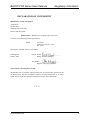

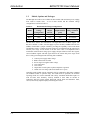
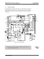
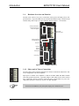
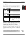
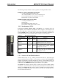
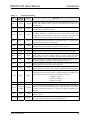
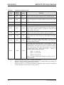
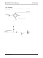
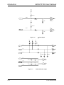
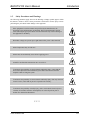

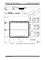
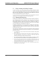
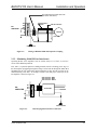
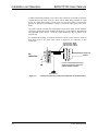
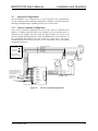
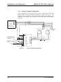
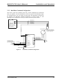
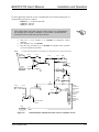
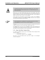
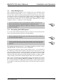
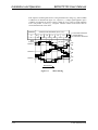
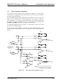
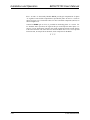
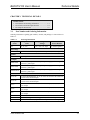
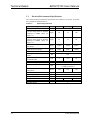
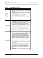
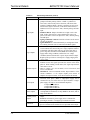
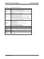
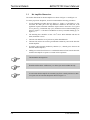
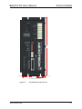
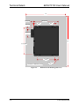
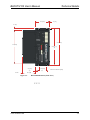

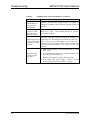
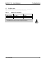

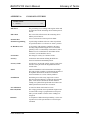
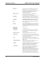
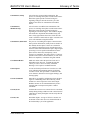
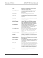
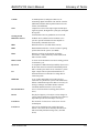
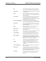
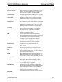
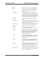
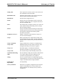
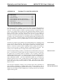
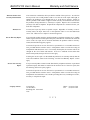
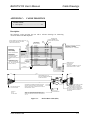
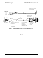


![PDF format [User manual]](http://vs1.manualzilla.com/store/data/005732328_1-c6f560cc59c28b45e6e6b9e007201668-150x150.png)