1
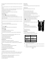
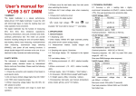
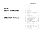
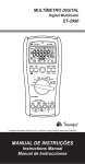
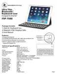
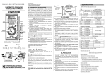
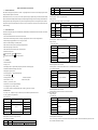
Digital True RMS Multimeter Instruction Manual 1. GENERAL DESCRIPTION This multimeter with highly stable performance is a reliable 3 6/7 digit digital multimeter. It uses the LCD with 23mm-high figure to make the 60V 10mV 600V 100mV 750V 1V <200V 50Hz~5kHz & ≥200V 50Hz~1kHz:±(1.0%+10) 50Hz~1kHz:±(1.0%+10) reading clear and make operation more convenient. Input impedance: approx. 10MΩ This multimeter can test DCV, ACV, VSD, DCA, ACA, resistance, capacitance, frequency, temperature, duty cycle, transistor, diode, and continuity. Overload protection:1000V DC or AC peak value 750V. This meter holds functions including true RMS, analog bar and unit symbol display, data holding, relative value measuring, maximal/minimal value Display: True RMS measuring, auto/manual range switching (RANGE), auto power off, backlight and warning functions. To assure high accuracy and resolution, it 3.2.4 Variable Frequency Voltage True RMS(VSD-V True RMS) adopts an 8-bit microprocessor and a dual integral A/D conversion IC as its core which can drive LCD directly. It is an ideal tool for labs, factories and radio-technology. 2. Range Resolution 6V 1mV 60V 10mV 600V 100mV 750V 1V SAFETY PRECAUTIONS The instrument is designed according to IEC1010 standard (safety standard issued by International Electro technical Committee). Please read the following before operation. 2.1 Check the connection and insulation of test leads to avoid electric shock 2.2 To avoid electric shock and damage to the meter, do not input voltage higher than DC 1000V or AC 750V during measurement. 2.3 When measuring voltage higher than DC 60V or AC 40V, please be careful. 2.4 Select correct function and range to avoid fault operation. 2.5 Please move the test leads away from test points when switching the function. Range Accuracy Resolution 0.1μA 600uA 1μA ±(1.0%+3) 60mA ” GND, “ ” dual insulation, 10μA 100μA 600mA ” Low battery indication 6A 3. * 3.2.5 DC Current(DCA) 6000uA ” Operator must refer to manual, “ ±(3.0%+10) Display: True RMS 2.8 Introduction of safety symbol: “ ±(5.0%+10) Overload protection:1000V DC or AC peak value 750V. 2.7 Please don’t modify the circuit arbitrarily, it may cause safety problem ” exists high voltage, “ 60Hz~200Hz ±(2.0%+10) Input impedance: approx. 10MΩ 2.6 Please don’t input voltage in current terminal. “ Frequency response/ Accuracy 30Hz~60Hz 1mA ±(2.0%+5) 20A FEATURES 10mA 3.1 General Characteristics Maximum voltage drop: 300mV for mA and A range. 3.1.1 Display:LCD; Maximum input current: 20A for 15 seconds. 3.1.2 Max display: 6000 (3 6/7) digits, automatic polarity, unit symbol and 61 section analog display; Overload protection:0.5A/250V fast action fuse for mA fuse;13A/250V fast action fuse for A input. 3.1.3 Measurement method: double integral A/D conversion;; 3.2.6 AC Current(True RMS) 3.1.4 Sampling rate: approx.3 times/sec. Range 3.1.5 Over-range display: “OL” displayed in the highest digit. 600uA 3.1.6 Low battery display:“ 6000uA ” ℃, relative humidity: <80% ; 3.1.7 Working environment: (0~40) ℃, relative humidity: <80% 3.1.8 Store condition: (-10~40) 3.1.9 Battery:1 piece 9V battery(6F22); 3.1.10 Dimension: 185×93×35mm (length*width*height); 3.1.11 Weight: approx..290g((including battery); 40mA Accuracy/Frequency response Resolution 0.1μA ±(1.2%+20) / (40Hz-5KHz) 1μA 10μA 100μA 600mA 6A ±(1.5%+20) / (40Hz-400Hz) 1mA 20A ±(2.5%+20) / (40Hz-400Hz) 10mA Maximum voltage drop: 300mV for uA, mA and A range. 3.1.12 Accessories: test leads, user manual, temperature probe, crocodile clip, gift box, and 1*9V battery. 3.2 Technical Features 3.2.1 Accuracy: ±(a% × reading data + digits). To assure accuracy, the environment temperature should be (23±5) <75%. One year guarantee since production date. Maximum input current: 20A for 15 seconds. Overload protection: 0.5A/250V fast action fuse, 13A/250V fast action fuse. ℃, relative humidity should Display: True RMS 3.2.7 Resistance (Ω) 3.2.2 DC voltage (DCV) Range Accuracy Resolution Range Accuracy Resolution 600Ω ±(0.8%+5) 0.1Ω 600mV ±(1.0%+5) 0.1mV 6kΩ 1mV 60kΩ 10mV 600kΩ 100mV 6MΩ 1V 30MΩ 6V 60V ±(0.5%+3) 600V 1000V ±(1.0%+3) 1Ω ±(0.8%+3) 10Ω 100Ω 1kΩ ±(1.2%+5) 10kΩ Input impedance: approx. 10MΩ Open circuit voltage: 600mV Overload protection:1000V DC or AC peak value 750V. Overload protection: 250V DC/ AC peak 3.2.3 AC voltage (ACV True RMS) NOTE: At 600 Ω range, connect the test leads to measure the wire resistance, then subtracts it from the real measurement, or press “REL” to clear Range Resolution 6V 1mV Frequency response/ Accuracy 50Hz~5kHz:±(1.0%+10) 5kHz~20kHz:±(1.5%+10) the wire resistance and read the value directly. 3.2.8 Diode and Continuity Test Range Terminal Description Test Condition Diode forward voltage drop reverse voltage is approximate 1.5V. Open circuit voltage is approximate 0.5V continuously. Overload protection: 250V DC or AC peak value NOTE: Do not input voltage at this range. 3.2.9 Capacitance(C) Range Accuracy Resolution 40nF ±(2.5%+10) 10pF uA/mA and duty cycle coefficient. COM Common terminal for all measurements VΩHz Input terminal for voltage, continuity, resistance, diode, capacitance, frequency, and duty cycle coefficient hFE Input terminal for triode measurement. TEMP Input terminal for temperature measurement. measurements. Symbol DC voltage measurement. Press DC/AC to shift between DC/AC voltage measurements. Press Hz/DUTY to shift 100pF 4μF ±(2.5%+5) 10nF 400μF 100nF Overload protection: 250V DC/ AC peak 3.2.10 Frequency(Hz) Range Accuracy Resolution 10Hz 0.01Hz 100Hz 0.1Hz 1000Hz ±(0.5%+4) 10Hz 100kHz 100Hz 1MHz 1kHz 30MHz 10kHz Input sensitivity: 0.7V RMS. ℉ <400 Resolution ℃ ±(0.8% +4) ≥400℃ ±(1.5% +15) <750 Frequency measurement. Press DC/AC to choose diode test. Press DC/AC again to choose continuity test. ℃/℉ Temperature measurement. Press DC/AC to shift between hFE Triode magnification measurement ℃ and ℉ . DC current measurement (from 0 μA to 6000 μA). Press DC/AC for AC current measurement (from 0 μA to 6000 μA). DC current measurement (from 0 mA to 600 mA). Press DC/AC for AC current measurement (from 0 mA to 600 mA). ③Function Button ③-1. MAX / MIN: Recording of minimum and maximum values 1) Press MAX/MIN into MAX mode, which will store the maximum value of measurements; Press it again to start MIN mode, which will store the minimum value of measurements. 2) Under MAX/MIN mode, it will start manual range automatically. Under this mode, functions like RELΔ, HOLD, RANGE, and DC/AC will not 4) Under MAX/MIN mode, analog bar display and auto power off can’t be used. Display ℃ Capacitance measurement Hz 3) Under MAX/MIN mode, it will store maximum or minimum values automatically. 3.2.11 Temperature(℃/℉ ) -1000 ℃ Ω resistance measurement. Press DC/AC to choose diode test. Press DC/AC again to choose continuity test. be available. Overload protection: 250V DC/ AC peak Range Ω DC current measurement (from 0 A to 20A). Press DC/AC for AC current measurement (from 0 A to 20A). 1Hz 10kHz Variable frequency voltage measurement. Press Hz/DUTY to shift between frequency and duty cycle measurements. 100nF ±(5.0%+10) 2000μF between frequency and duty cycle measurements. 1nF 40μF 0F-1832 Input terminal for AC and DC microamp and milliamp measurements to 600mA (600mA can last 18 hours), frequency ②. Rotary switch: used to change the range and choose functions. 400nF -40 Input terminal for AC and DC current measurements to Max 20.00 A(15 seconds), frequency and duty cycle coefficient. Forward DC current is approximate 0.5mA, When the resistance under test is less than 30±10Ω, buzzer sounds Description A ℉ ±(0.8% +5) ≥750℉ ±(1.5% +15) 1 ℃ 5) Press MAX/MIN for 2 seconds it will exit MAX/MIN mode. ③-2. Hz/DUTY When measuring the Frequency, press Hz/DUTY will shift between frequency and duty cycle (1~99%) measurement. When measuring DC/AC ℉ voltage / current,press Hz/DUTY can choose voltage/frequency/duty cycle mode or current /frequency/duty cycle mode. ③-3. RELΔ Sensor: TP01 (K-type thermocouple) 1)Stores the present reading as a reference for subsequent readings. The display is zeroed, and the stored reading is subtracted from all subsequent NOTE: Do not input voltage at this range, it may cause damage to the meter. readings. REL 3.2.12 Transistor triode (hFE) 2) RELΔ function is only available under manual range mode. Measurement NPN or PNP Range 0 ~ 1000 Test Conditions Base current is approximate 15uA, Vce is about 4.5V -△reference (readings) value. = input value △ will enter manual range automatically. 3) Press REL △ mode, press REL△ again will exit REL△ mode. 4) Under REL 5) Under HOLD mode, press REL △ will exit HOLD mode. It will regard the current measuring value as reference value, and the reference value will be 4. OPERATION 4.1 Panel Description: subtracted by subsequent readings automatically. 6) Press RANGE, DC/AC, or switch the rotary will exit the RELΔ mode. (RELΔ symbol will disappear from LCD) 7)OL display:Under RELΔ mode, when input value over limit value, OL will be displayed. Press RELΔ to exit the RELΔ mode. When OL is displayed, meter can’t enter the RELΔ mode. ○ 1 .Input terminal: 8) Under RELΔ mode,analog bar display is not available. ③-4. HOLD/ LIGHT: Data Hold and Backlight A.HOLD: data hold 1) Press HOLD will enter HOLD mode, the current value will be hold, and symbol HOLD will be displayed. Press HOLD again can exit the HOLD mode. 2) Press RANGE, DC/AC, or switch the rotary will exit the HOLD mode. 4. Connect test leads to the test point; LCD will display polarity and voltage of the test point connected by the red test lead. B.LIGHT: backlight control Note: 3) Press HOLD more than 2 seconds will turn on the backlight. Press it for another 2 seconds will turn off the backlight. When backlight is on, it 1. Under manual range mode, if LCD displays “OL”, it means over range, you should select the higher range. will auto off in 10 seconds, unless you press HOLD for more than 2 seconds. 2. Do not input a voltage over DC 1000V. It may cause damage to the circuit of meter. ③-5.RANGE: Auto or manual ranging. 3. Be careful while measuring a high voltage circuit. DO NOT touch the high voltage circuit. Auto range is the default when you turn on the meter. Press RANGE it will enter manual range mode. Press RANGE can switch between the ranges 4. The built –in buzzer will beep to remind user, when the measuring voltage over DC1000V. available for the selected function. To return to auto ranging, hold the button down for more than 2 seconds. 4.3 ACV measurement ③-6.“DC/AC”: 1. Switch the knob to “ 1) DC/AC function button can choose DC or AC measurement under choose Ω, or mode. Under Ω (Ohm/Diode/Beeper) mode, press DC/AC can ℃ or ℉ . . Under temperature measurement, press DC/AC can choose ” range, and then press “DC/AC” to choose AC measurement. 2. Insert the black test lead in “COM” terminal and the red one in “V/Ω/Hz” terminal. 3. Auto range is the original states, it will display “AUTO” symbol,press “RANGE” key change to manual range mode,and 6V,60V,600V, 2)Keep this button down when turn on the meter, auto power off function will be canceled, the symbol APO will disappear. Under the dormancy 750V range is available. mode, press DC/AC will turn on the meter and will activate auto power off function. 4. Connect the leads to the electric circuit. LCD will display voltage of the two test points. 3)When there is no measurement in 15 minutes, the meter will auto power off and enter dormancy mode. In one minute before dormancy mode, Note: the buzzer will beep 5 times to remind user. Press any button will exit the dormancy mode. 1. Under manual range mode, if LCD displays “OL”, it means over range, you should select the higher range. ④. LCD: Display the data and unit symbol. 2. Do not input a voltage over AC 750V. It may cause damage to the circuit of meter. 3. Be careful while measuring a high voltage circuit. DO NOT touch the high voltage circuit. 4. The built –in buzzer will beep to remind user, when the measuring voltage over AC750V. Number Feature 1 - 2 AUTO 3 AC 4 - 5 DC 1. Switch the knob to “ Auto range mode. 2. Insert the black test lead in “COM” terminal and the red one in “V/Ω/Hz” terminal. AC voltage or current measurement. 3. Auto range is the original states, it will display “AUTO” symbol,press “RANGE” key change to manual range mode,and 6V,60V,600V, Indicates negative readings. 750V range is available. All the signal will be converted by a wave filter, and voltage with frequency higher than 1kHz will be prevented, and DC voltage or current measurement. or personal injury, please replace the battery as soon as the battery indicator appears. 7 RS232 8 MAX/MIN 9 HOLD 10 REL 11 12 APO 4.4 VSD True RMS voltage measurement Negative polarity indicator for the analog bar graph. Low battery indication. Warning: To avoid false readings, which could lead to possible electric shock 6 Invalid. Indicators for minimum-maximum recording mode. Display Hold is active. ” range. voltage with lower frequency can pass. By this way, it can improve the measurement results of composite wave produced by inverter and variable-frequency motor. 4. Connect the leads to the electric circuit; LCD will display voltage of the two test points. Note: 1. Under manual range mode, if LCD displays “OL”, it means over range, you should select the higher range. 2. Do not input a voltage over AC 750V. It may cause damage to the circuit of meter. 3. Be careful while measuring a high voltage circuit. DO NOT touch the high voltage circuit. Relative (REL) mode is active. 4. The built –in buzzer will beep to remind user, when the measuring voltage over AC750V. Diode test mode and the continuity beeper is on. 4.5 DCA measurement Auto power off mode is on. 1. Switch the knob to “ Indicator for Hi measurement mode. 2. Insert the black test lead in “COM” terminal and the red one in “uAmA” terminal (Max. 600mA) or to “A” terminal (Max.20A); ” range. The default is DCA measurement, press "DC/AC" can choose DC or AC measurement. At Ω range, press DC/AC can choose Max 6000MΩ high resistance measurement. Accuracy is not 3. Connect the leads to the electric circuit. LCD will display polarity and current of the test point connected by the red test lead. referable. Note: At Hz range, press DC/AC can choose Max 1000MHz high frequency measurement. Accuracy is not 1. Firstly users should select the highest range, if users not sure about the range of current under test, and then select the proper range based on referable. High frequency measurement needs special accessories: a device can divide frequency to displaying value. 128, or keep the impulse amplitude above 200mV RMS. We don’t provide those special accessories. 2. If the LCD displays “OL”,it means the current is over range. Now you need to select a higher range. hFE, ℃, ℉ hFE (Triode magnification measurement) Degrees Celsius, Degrees Fahrenheit 3. Maximum input current is 600mA or 20A(subject to where the red test lead insert in), current higher than that will damage the fuse, and may % Percent (used in duty cycle coefficient measurement) cause damage to the circuit of meter. RPM Rotational speed (test RPM needs special accessories: a device which can convert rotate speed to 4.6 ACA measurement electrical pulse, and the electrical pulse should be above 200mV RMS. We don’t provide these 1. Switch the knob to “ accessories.) 2. Insert the black test lead in “COM” terminal and the red one in “uAmA” terminal (Max. 600mA) or to “A” terminal (Max. 20A); MΩ, kΩ, Ω Megohm, Kilohm, Ohm 3. Connect the leads to the electric circuit. LCD will display polarity and current of the test point connected by the red test lead. Hz, kHz, MHz Hertz, Kilohertz, Megahertz Note: mV, V Millivolts, Volts 1. Firstly users should select the highest range, if users not sure about the range of current under test, and then select the proper range based on A, μA, mA Amperes (amps), Microamp, Milliamp displaying value. μF, nF Microfarad, Nanofarad 2. If the LCD displays “OL”,it means the current is over range. Now you need to select a higher range. 13 14 Indication Hi ” range. Press "DC/AC" to choose AC measurement. ⑤. Holster and Battery door. 3. Maximum input current is 600mA or 20A(subject to where the red test lead insert in), current higher than that will damage the fuse, and may 4.2 DCV measurement cause damage to the circuit of meter. 1. Switch the knob to " " range. The default is DCV measurement, press "DC/AC" can choose DC or AC measurement. 4.7 Resistance measurement 2. Insert the black test lead in “COM” terminal and the red one in “V/Ω/Hz” terminal. 1. Switch the knob to “Ω 3.Auto range is the original states, it will display “AUTO” symbol,press “RANGE” key change to manual range mode,and 600mV, 6V, 60V, 600V, 2. Insert the black lest lead in “COM” terminal and the red one in “V/Ω/Hz” terminal.; 1000V range is available; 3. Auto range is the original states, press “RANGE” key change to manual range mode. ” range, and connect the leads with the resistor under test. 4. Before measuring low resistance, you should make the test leads short-circuit at first, and then press “REL”. By this way, you can get the actual 4.12 Transistor Test (hFE) value of the resistance. 1. Switch the knob to hFE range. Note: 2. Define the transistor is NPN or PNP type, then insert the emitter, base and collector separately in the relative hole. 1 Firstly users should select the highest range, if the value of resistance is unknown beforehand, and then select the proper range based on 5. METER MAINTENANCE displaying value. 2. The LCD displays “OL” when the resistance is over the selected range. The knob should be adjusted to a higher range. When measuring value is The meter is a precise instrument. Random changes to the circuit are not allowed. over 1MΩ, the reading will take a few seconds to be stable. It’s normal for high resistance measurement. Note: 3. When input terminal is in open circuit, LCD will display “OL”. 1. Don’t input the voltage value higher than DC 1000V or AC 750V rms. 4. Before measuring in line resistor, make sure that the power is off and all capacitors are discharged completely. 2. Don’t input voltage at current, resistance, diode and continuity range. 5. Do not input any voltage at resistance range. 3. Don’t make any measurements when the battery isn’t installed or the back cover isn’t fixed. 4. Before replacing fuse, please remove the test leads from the measuring point and turn off the power. 4.8 Diode and Continuity test: 1. Switch the knob to “Ω ” range, and press “DC/AC” key to select diode measurement mode. 5. Keep the meter away from water, dust and shock. 2. Insert the black test lead in “COM” terminal and the red one in “V/Ω/Hz” terminal (the polarity of red lead is “+”) 6. Don't expose the meter under high temperature, high humidity, combustible, explosive and strong magnetic place. 3. Forward measurement: connect red test lead to the positive polarity and the black test lead to the cathode polarity of the diode. LCD will display 7. Wipe the case with a damp cloth and detergent. Do not use abrasives and alcohol to clean the meter. the approx. value of forward voltage drop. 8. If do not operate for a long time, you should take out the battery to avoid leakage damage. 4. Backward measurement: connect red test lead to the cathode polarity and the black test lead to positive polarity of the diode. LCD will display 9. When “ “OL”. 9-1. Follow picture 2, and remove the holster at first. 5. The complete diode testing includes forward and backward measurement, if the result doesn't meet the descriptions above, it means the diode is 9-2.Unlock the battery door and remove the cover; broken. 9-3. Replace the old battery with the new one. For longer using life, it's better to use alkaline 6. Press “DC/AC” key to select the Continuity measurement mode. battery. 7. Connect test leads to two points of tested circuit, if the resistance is less than (30±10) Ω, the buzzer sounds. 9-4. Fix the battery door. Note: 9-5, Follow the picture to put on the holster. 1. Don’t input voltage at “ ” range. ” symbol is displayed, you should replace the battery according to the following steps: 10. Fuse change: When replacing fuse, please use fuse with same type and specification. 2. Make sure the power is off and all capacitors are discharged. Any AC signal will make the buzzer sounds. 10-1. Follow picture 2, and remove the holster at first, then unlock the battery door and remove the 4.9 Capacitance measurement cover; 1.Switch the knob to “ 10-2. Take out the fuse and put on a new one. ”range; 2. Insert the black lest lead in “COM” terminal and the red one in “V/Ω/Hz” terminal.; 10-3. Fix the battery door, and put on the holster. 3. If the LCD doesn’t display “0”, press “REL” to clear the reading; 6. TROUBLE SHOOTING 4. Connect the capacitor to “COM” and “VΩHz” terminal. (Note: the red test leads is for positive pole+).LCD ○ displays capacitance value. Note: If the meter does not work properly, please check the meter as following steps: (If the problems still cannot be solved, please refer to repairing center or contact the local dealers.) 1. Don’t input voltage or current to the “VΩHz” terminal when measuring the capacitance or the capacitor still in the “Cx” terminal. 2. In order to assure the accuracy, please press “REL” to clear the reading before testing. Fault Turn on the power Replace battery Replace battery No current or temperature input Replace fuse Error Value Replace battery No reading on LCD 4. The capacitor must be completely discharged before testing. 5. The reading of 400uF range will take more than 15 seconds to be stable. signal appears 4.10 Frequency measurement 1. Insert the black lest lead in “COM” terminal and the red one in “V/Ω/Hz” terminal.; Solution 3. There is only the auto range mode under the capacitance range. 2. Switch the knob to “Hz” range,connect the test leads or shielded cable to the signal source or the load which is tested. 3.Press “Hz/DUTY” key to choose frequency/duty cycle measurement,LCD will display the frequency or duty cycle of the tested signal source. Note: 1. There is only the auto range mode under the frequency range; 2. The meter can still work if the input current is higher than 10V rms, but the accuracy is not guaranteed; 3. In noisy environment, it's better to use shield cable to measure a low signal; 4. When measuring high voltage circuit, do not touch the high voltage circuit; 5. Don’t input voltage higher than 250V DC or AC peak value, or it may damage the meter. 4.11 Temperature measurement 1. Switch the knob to “℃ / ℉” range, and press “DC/AC” key to choose ℃ or ℉ measurement. 2. Insert the cold terminal (free end) of thermocouple in “TEMP”socket,and put the working terminal (temperature measuring end) of thermocouple on the surface or inside the object to be tested. Then you can read temperature from the screen, and the data is in Centigrade. Note: 1. If insert the thermocouple oppositely, it will display the wrong value. When the temperature is rising, the value will be down. 2. When the input terminal is open circuit, it will display the environment temperature. 3. Don’t change the temperature probe randomly, or the accuracy will not be guaranteed. 4. Don’t input voltage at temperature range. The specifications are subject to changes without prior notice. The content of this manual is regarded as correct. If users find out any mistakes or omissions, please kindly contact the manufacturer. The manufacturer will not be responsible for accidents and damage caused by improper operations. The functions described in this User Manual shall not be considered as the reason for any special usages. 201187/V0.0