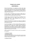
1
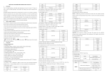
User Manual of BM3548 and BM3549
Insulation Tester and Multimeter
III. Name and function of parts (see the figure)
Distinguished users:
Thank you for purchasing the meter of our company. To use the meter
correctly, please read the operating instructions thoroughly and carefully before
use it, especially the section of “Safety information”.
Please keep the operating instructions in a safe place after reading it, putting it
where the meter is or keeping it in handy for future reference.
Attention: A test cable is provided for the meter. It is not allowed to
perform insulation test by holding the test cable with your hands. Ensure
that the to-be-tested object is securely clamped and keep your body away
from the circuit before press the TEST key to output high voltage.
I. Overview
Welcome to use the product!
BM3548/49 digital multimeter with auto range selection is a real digital
insulating resistance tester + digital millimeter. It has features of complete
functions, high accuracy, reliability in operation, and convenience in use. Output
test voltage can be switched among 250V/500V/1000V/2500V, depending on
different models. An ordinary insulating resistance meter can not measure the
output high voltage of its own. When the output high voltage of the insulating
resistance meter doesn’t conform to the rated value, it is not easy for the user to
find the unconformity so that deviation of the measured result is over large
sometimes and causing hidden troubles in safety. BM3548/49 can monitor the
output high voltage in a real-time way. At any time, the user can observe actual
measurement voltage that is output by the meter, effectively avoiding
misjudgment caused due to output voltage not conforming to the rated value.
The measurement range of the meter can reach up to 40GΩ. The measurement
time can be set up according to requirements. After a measurement is completed,
the measured result can be kept automatically. Functions of the digital
multimeter include AC/DC voltage, current, resistance, capacitance, frequency,
diode, and ON/OFF measurement. The functions of the digital multimeter are
completely separated from those of the insulating resistance tester. When use
functions of the multimeter, you need not be worried that you would suffer
electric shock due to high voltage generated by the insulating resistance tester.
The product is applicable to measurement of the insulating resistance of various
insulating materials and electric equipments such as transformers, motors,
cables, switches, and electric apparatuses. It is also applicable to maintenance,
test, and inspection of various electric equipments. It is compact in structure,
convenient to carry, and an ideal electrical and electronic testing meter of yours.
1. Function switch knob
Switch among power ON/OFF, measurement voltage of the insulating
resistance, and various functions of the multimeter.
2.TEST/STOP key: it is used to measure the insulating resistance
RANGE key: it is used to switch between hand-operated and auto range mode
as the meter is used as the multimeter. The function is not available when the
meter is used as the insulating resistance tester. On startup, the meter is preset
to auto range mode. Press the key to switch to hand-operated range mode. In
hand-operated range mode, every time press the key, the range goes up one
level until to the maximum level. After the maximum level is reached, every
time press the key, the range goes to the minimum level. The process is
repeated. If press and hold the key over 2 seconds, the meter is switched to
auto range mode.
3.SELECT key: it is used to set the measurement time of the insulating
resistance as well as various function switch of the same position
4.DH/BL key
Data hold/backlight function: press the key to lock the displayed result.
Press it again to restore normal measurement (when OL is displayed in the
meter, Hold function is not available). Press and hold the key for 2 seconds to
switch between backlight on/off (in adjustment mode, backlight is not
available).
5.L (LINE) input terminal (connected to line terminal of the to-be-tested
object).
6.V/Ω/mA/Hz/CAP input terminal: common positive input terminal of the
digital multimeter;
7.COM/G input terminal (COM is common EARTH of the multimeter /G is
shielded terminal of the insulating resistance).
8.E (EARTH) input terminal (connected to EARTH terminal of the
to-be-tested object)
9.Liquid crystal display
Small 8888: measured value of high voltage
of the insulating resistance
-8888: measured value of various functions
Min: measurement time of the insulating
resistance (minute)
OL: overflow display, indicating the measured
value exceeds the maximum display value.
ERR: indicating that serious current leakage
or short circuit occurs to the equipment
- + : Battery capacity is insufficient
10 Indicator light of high voltage
11 Holding box of the test cables
12 Ring used to fasten the hanging strip
IV. General characteristics
(1) Auto range: “OL” will be displayed for overload.
(2) Display mode: Liquid crystal display; maximum display: 4000;
(3) Sampling rate: 2 times per second;
(4) The meter can display actual insulation test voltage. LED light is used to
indicate high voltage output status;
(5) Operating environment: 0°C-40°C, less than 75%RH;
(6) Storage environment:-10°C-60°C, less then 80%RH;
(7) Maximum power consumption: 4.5W; minimum power consumption 18mW.
(8) Indication for insufficient battery capacity: “- + ” is displayed;
(9) Power supply: 6 pieces of AA 1.5V battery (LR6×6)
(10) Auto power off: The multimeter is turned off automatically in approx. 15
minutes after it is turned on if no key is pressed or the knob is not turned.
(11) External dimension: 170(length)×156(width)×64(height)mm
II. Safety information
(1) Description of safety marks:
Warning:
important safety information the user must read!
Danger: high-voltage electric shock is present!
Double-insulated protection
(2) Read the operating instructions carefully before use the meter.
(3) It is strictly prohibited to use the meter before its rear cover is put in place.
Otherwise, it might cause an electric shock.
(4) Check and make sure the insulating layer of the test cable is in good
condition without any breakage.
(5) To avoid electric shock, do not touch the test cable and the circuit under test
when performing a test.
(6) Make sure one end of the test cable is securely inserted into the terminal.
(7) During test, any range must not exceed its specified maximum input value.
(8) During test, do not operate the switch knob for changing a range to avoid
damaging the meter.
(9) DC voltage over 50V or AC voltage over 36V can cause danger of electric
shock. Be careful when taking measurement.
(10) Before performing insulation test, make sure the range selection switch has
been set within an appropriate voltage range.
(11) Do not perform insulating resistance test in a combustible environment.
Spark may cause explosion.
(12) Stop using the meter, if its case or test cable is broken during use and the
metal is exposed
(13) When open the rear cover for changing battery, make sure the test cable has
been removed out of the test terminal and the range switch switched to
OFF position.
(14) Take the battery out when the meter will not be used for a long time.
(15) When “- + ” is displayed in the meter, it is necessary to change the battery
in time to ensure measurement accuracy.
1
measurement of insulating resistance after high voltage is output. The
improper operation is very easy to generate spark, cause fire disaster, and
damage the meter.
(12) Weight: Approx. 650 grams (including the battery)
V. Technical characteristics and operating description of the insulation
tester
Accuracy:±% reading ± number, one-year warranty
Environment to guarantee the accuracy: 23°C±5°C, less than 75%RH
Rated measurement voltage, valid measurement range, and precision
Rated voltage
250V
500V
1000V
2500V
Measurement range
0.25M-400MΩ
0.5MΩ-4GΩ
1.5M-40G
5M-40GΩ
Special attention in operation:
Before test, make sure the to-be-tested circuit is not electrified. Do not take
measurement of any electrified equipment or electrified circuit. During test,
dangerous voltage output exists in the meter. Be sure to operate it carefully.
Ensure the to-be-tested object is securely clamped and keep your hands away
from the test clamp before press TEST key to output high voltage.
Attention in operation:
When use 500V measurement voltage to measure resistance less than 2MΩ,
1000V to measure resistance less than 5MΩ, and 2500V to measure resistance
less than 10MΩ, measurement time must not exceed 10 seconds.
5) Power off
After the test is completed, release lock status of the meter and observe
voltage display value of the insulating resistance tester. When it is less than 50V,
turn the range switch knob to OFF position, and then remove the test cable. The
test is over.
Attention: the meter can not be turned off automatically when it is used as
an insulating resistance tester. Please turn the range switch knob to OFF
position after the test is over.
Accuracy
0.2M-200MΩ:±3%rdg±5,
200M-4GΩ:±5%rdg±5,
4G-40GΩ:±10%rdg±5
Display range
Rated voltage
250V
500V
1000V
2500V
Display range (auto range )
4M/40M/400MΩ
4M/40M/400M/4GΩ
40M/400M/4G/40G
40M/400M/4G/40GΩ
Resolution
1k/10K/100KΩ
1k/10K/100K /1MΩ
10k/100K/1M /10MΩ
10k/100K/1M /10MΩ
Characteristics of the measurement terminal
Rated
voltage
Allowed range
of open circuit
voltage
The measurement resistance value that
can maintain lower limit of the rated
voltage
short circuit
current
250V
90%-110% of the
rated voltage
250KΩ (ERR is displayed when it is
less than 200KΩ)
Not less than
1.5mA
500V
500KΩ (ERR is displayed when it is
less than 400KΩ)
1000V
1.5MΩ (ERR is displayed when it is
less than 1MΩ)
2500V
5MΩ (ERR is displayed when it is less
than 2MΩ)
Notices in use of the insulating resistance tester
1. Brief introduction
The insulating resistance tester can be used to verify completeness of motor,
transformer, switching equipment, and coil and cable of electric equipment. For
example, when electric cable or switching equipment (low capacitance
equipment) is tested, time-related capacitive leakage current is not noticeable
and would quickly drop to zero. Within a short time (one minute or less), it will
reach a stable conductive leakage current quantity of, providing a good
condition for spot-check of reading/short-time impedance test.
In the other hand, time-related current will last for several hours when the
equipment under test is long cable, large-sized motor or generator (high
capacitance equipment). The current would cause ceaseless change of the
reading of the insulating resistance tester. It is impossible to obtain an accurate
reading. If trend analysis among readings can be made, for example, step
voltage or medium absorption test, the situation can be overcome. The analysis
doesn’t rely on a single reading, but on a large quantity of related readings. As
time-related current drops quickly when low capacitance equipment is tested,
results from multiply tests are the same. Therefore, use of the multiply test
method will waste time.
2, Test in assembly
The most important reason of the insulation test is to ensure the public and
individual safety. Through high voltage DC test among live wire, earthing and
earthing wire, you can eliminate short circuit or earthing phenomenon that is
dangerous to the human life. Usually, the test is performed after preliminary
equipment installation is completed. Performing the test can find connection
error and defective equipment, guarantee high quality installation, and prevent
fire disaster or explosion.
3. Test in maintenance
Another important reason of the insulation test is to protect and lengthen
service life of electric system and motor. Electric system is affected by such
factors as dust, grease, temperature, stress, and vibration for a long time. These
conditions may cause insulating deterioration, loss in production, and even fire
disaster. Regular maintenance and test can provide very valuable information
of system wear and tear status and help forecast system failure possibility.
Solving problems in time can guarantee that a system operates without any
fault and effectively lengthen service life of various equipments.
To obtain meaningful insulating resistance result, an electrician should check
the to-be-tested system carefully before take measurement. When the following
conditions are satisfied, the best results will be obtained:
1) Shut down the system or equipment and disconnect it from other circuits,
electric switches, capacitors, electric brushes, lightning rods, and circuit
breakers. Ensure the test is not affected by leakage current that flows through
switches and over-current protection components.
2) The temperature should be higher than dew point of the environmental air. If
the condition is not satisfied, a layer of water smoke will be formed in the
insulating surface. In some cases, it would be absorbed by insulating material.
3) In surface of the conductor there should be no carbon and other impurity that
are easy to form a conductor.
4) The applied voltage should not be too high. When low voltage system is
tested, too high voltage would cause overload or damage a insulator.
5) The to-be-tested system should be fully discharged to the earth. The earthing
discharge time should be approx. fivefold of the charge time.
6) Temperature influence is worth attention. As insulating resistance is in
inverse ratio with insulating material temperature (the higher the temperature is,
the lower the impedance is). The recorded impedance reading would be changed
by insulating material temperature. It is suggested to perform measurement in a
standard temperature of 20℃ (68 oF). Compare a reading with a result at a
temperature of 20℃ according to conventional practice. with a temperature over
20℃, the impedance value at 20℃ will be twofold of its reading every time the
temperature goes up for 10℃ (18 oF); with a temperature under 20℃, the
impedance value at 20℃ will be one half of its reading every time the
Usage for insulating resistance measurement
Danger: If there is any measurement error, it may cause personal injury
and meter failure. Operate it only after read the operating instructions carefully
and thoroughly. Our company will take no responsibility for the accident not
caused due to any reason of our company.
Operating description
1. Safety information
1) Watch out for high-voltage electric shock. When completing the
insulating resistance test, remove the test cable only after making sure high
voltage across the tested object is less than 50V.
2) During measurement, do not touch the object under test and watch out for
high-voltage electric shock.
3) When test the insulating resistance, the object should not be electrified.
Make sure the to-be-tested object is securely earthed. Before test, it is necessary
to short-circuit and discharge two test terminals of the to-be-tested object.
4) When test the insulating resistance, make sure no external voltage is
applied to the test circuit.
5) Before starting test, make sure position of the range switch knob is correct
and the test cable is securely connected.
6) After press the high voltage key, high voltage from 250V to 2500V will
be output between L terminal and E terminal (depending on different models
and positions). Here, be sure not to touch the meter and exposed part of the
object under test. Otherwise, danger of electric shock would occur.
2. Insulating resistance test
1) Connection of the test terminals
Insert one end of the test pen with a high voltage test bar into L terminal
socket of the meter. Insert one end of the test cable with a test clamp into E
terminal socket of the meter. Insert one end of the test cable with a black test
pen (the pen with a clamp) G terminal socket of the meter. Make a good
connection respectively.
2) Test connecting cable
Connecting cable of E terminal socket of the meter is earthing cable;
Connecting cable of L terminal socket of the meter (with a high voltage test bar)
is circuit cable;
Connecting cable of G terminal socket of the meter (the pen with a clamp) is
shielding cable and connected to surface of the to-be-tested object to prevent
surface leakage and affect impedance test.
3) Rated voltage selection
Select a rated voltage you need in the insulating resistance test. Turn the range
switch knob to a corresponding voltage position, and press “SELECT” to
make selection among 1min/2min/10min according to test time requirement
4) Connect pen of the test bar to another terminal of the to-be-tested object.
Press high voltage switch (TEST/STOP). Here, the red indicator light turns
on, indicating high voltage output for test is connected. Actual high voltage
value can be displayed in the meter.
After the test is started, numerical value is displayed in the meter. The
displayed value is the insulating resistance value of the object under test. For
convenience of use, when the set test time comes, the meter cuts high voltage
off automatically, and locks and saves the measured result. When the
measured result is less than the set minimum resistance value under the
measurement voltage, “ERR” is displayed in the meter. If there is a need to
remeasure, press any key to release the lock status and start the measurement
over again.
Attention: do not short-circuit the two test pens with high voltage output or take
2
temperature goes down for 10℃(18 oF). For example, when 10MΩ impedance
at 40℃ is converted into the impedance at 20℃, its value is 40MΩ. The
conductor temperature can be measured with a non-contact infrared temperature
tester
4,
Work safety
To guarantee safety is responsibility of every body. However, your safety is at
your own hands. No tool can guarantee your safety. Only safe equipment and
safe work habit can provide you with the safest protection. The followings are
some safety tips you should obey:
★ In any time, put the circuit in power-off status as possible as can. Take
appropriate cut-off/turn-off steps. If the ON/OFF status is undetermined, assume
the circuit is electrified. You can use AC/DC voltage measurement function of
the meter to determine if the circuit is in power-on status.
★ Use protection device for the power-on circuit: Use insulating tools. Put up
wear fireproof suit, goggle, and insulating gloves. Take off watch or other
adornment. Stand on an insulating pad.
★ Draw lesson from experienced electricians: Keep one hand away from
other objects. This way will reduce the possibility that closed-loop current goes
through your thorax and heart.
★ When perform insulating resistance test:
※ Do not connect the insulation tester to an electrified conductor equipment.
Follow manufacturer’s suggestions to perform the test.
※ Cut off fuse, electric switch, and circuit breaker. Turn off the to-be-tested
equipment.
※ Disconnect branch circuit wire, earthed wire and other equipment from the
to-be-tested equipment.
※
Before and after the test, discharge capacitors of the to-be-tested object.
Some equipment may have automatic discharge function.
※ Check if there is leakage current going through fuse, electric switch, and
discharge circuit breaker. Leakage current would cause incorrect test result.
※
When the insulation is in bad condition, equipment would generate
electric arc. Therefore, do not use the insulation tester in a dangerous
environment with combustible and explosive gas.
※ When connect test cable, use a pair of insulating rubber gloves.
5, Important tips
What the insulating resistance tester measures is surface-to-surface resistance
value of the object under test, but not point-to-point one. Therefore, the wire
should not be connected to surface of a non-conductive object (such as cable
rubber and plastic case). It is necessary to use a conductive material (such as
silver paper) to cover surface of the to-be-tested object, and next, connect a
wire to the conductive surface, and then, you can perform the measurement.
IV. Technical characteristics and operating description of the multimeter
Accuracy: ±% reading ± number, one-year warranty
Environment to guarantee accuracy: 23°C±5°C, less than 75%RH
DC voltage (DCV)
Range
Accuracy
Resolution
400mV
0.1mV
±(0.5%+5d)
4V
1mV
40V
10mV
400V
100mV
1000V
±(0.8%+5d)
1V
Input impedance: 400mV>1000MΩ; 10MΩ for other ranges.
Maximum input voltage: DC or AC peak value 1000V.
AC voltage (ACV)
Range
Accuracy
Resolution
4V
1mV
±(0.8%+5d)
40V
10mV
400V
100mV
700V
±(1%+5d)
1V
Frequency range: 40Hz~400Hz (400V and 700V range is 40Hz~100Hz).
Maximum input voltage: DC or AC peak value 1000V.
Display: Average (Sine wave virtual value calibration)
DC current (DCA)
Range
Accuracy
Resolution
±(0.8%+5d)
40mA
10mA
400mA
100mA
Overload protection: 0.5A/250V fuse.
AC current (ACA)
Range
Accuracy
Resolution
±(1%+5d)
40mA
10mA
400mA
100mA
Overload protection: 0.5A/250V fuse.
Resistance
Range
Accuracy
Resolution
400Ω
0.1Ω
±(0.8%+5d)
4kΩ
1Ω
40kΩ
10Ω
400kΩ
100Ω
4MΩ
±(1%+3d)
1kΩ
40MΩ
±(2%+3d)
10kΩ
Overload protection: 250V RMS
Capacitance
Range
Accuracy
Resolution
40nF
10pF
±(3%+5d)
400nF
100pF
4μF
1nF
40μF
10nF
Overload protection: 250V RMS
Frequency (FREQ)
Range
Accuracy
Resolution
40Hz
0.01Hz
400Hz
0.1 Hz
4KHz
1 Hz
±(0.5%+3d)
40KHz
10 Hz
400KHz
100 Hz
1K Hz
4MHz
Overload protection: 250V RMS
Input sensitivity: 2V RMS
Attention: If the frequency amplitude under test is larger than 50V, please press
“SELECT” key of ACV function to enter frequency function, and then
make the measurement.
Forward voltage of the diode
Display approximate forward voltage value of the diode. Test condition:
Forward DC current of approx. 0.5mA, reverse DC voltage of approx. 1.5V.
Continuity test
When the ON resistance is less than approx. 380Ω, the buzzer in the meter
buzzes. Test condition: open circuit voltage of approx. 0.5V.
Operating description of the digital multimeter
AC/DC voltage measurement
Turn the switch knob to “V=” or “V~” range. Insert one end of the black pen
into the jack of “COM”. Insert one end of the red pen in the jack of “V/Ω/mA
/Hz/CAP”. Connect the other end of the two pens in parallel to two terminals
of the to-be-tested circuit. The value on the LCD screen can be directly read;
Attention: 1) Input voltage should not exceed the limited value. If does, there
is danger of damaging the meter circuit. When the displayed value is larger
than DC1100VHU or AC770V, OL is displayed in the meter, indicating the input
voltage has exceeded maximum limit value of the meter; 2) When perform
measurement of high voltage circuit, be sure that human body will not contact
the high voltage.
AC/DC current measurement
Turn the switch knob to “mA” range. Here, the meter is preset to DC current
measurement mode. Insert one end of the black pen into the jack of “COM” and
one end of the red pen into the jack of “V/Ω/mA/Hz/CAP”. If take measurement
of DC current, connect the other end of the two pens in series to the to-be-tested
circuit. The value on LCD screen can be directly read. If take measurement of
AC current, press “SELECT” key to switch to AC current range. Connect the
other end of the two pens in series to the to-be-tested circuit and read the
displayed value.
Attention: 1) Input current must not exceed the limited value. If does, there
is danger of damaging the meter circuit.
Resistance and Continuity measurement
Warning! When perform resistance and continuity measurement, it is
necessary to guarantee that no voltage is applied across the to-be-tested circuit or
component.
Set the switch knob to Ω
position. Here, the meter is preset to resistance
range. Insert one end of the red pen into the jack of “V/Ω/mA /Hz/CAP”, and
one end of the black one into the jack of “COM”. Connect the other end of the
two pens in parallel to two terminals of the to-be-tested circuit or component
and read the resistance value.
Press “SELECT” key to switch to
range. When the tested resistance
value is less than approx. 380Ω, the buzzer would buzz. This is continuity test.
When the pens are open-circuited or input is overloaded, “OL” will be
displayed on the screen.
Forward voltage measurement of the diode
Turn the switch knob to “Ω
” position. Press “SELECT” key to switch to
range. Insert one end of the red pen into the jack of “V/Ω/mA /Hz/CAP”
and one end of the black pen into the jack of “COM” (polarity of the red pen is
“+”). Connect the other end of the two pens in parallel to two terminals of the
to-be-tested diode and read the forward voltage value. When the diode is
reversely connected or the input terminal is open-circuited, “OL” will be
displayed on the screen.
Capacitance measurement
Warning! When perform capacitance measurement, it is necessary to
guarantee the to-be-tested capacitor is completely discharged.
Turn the switch knob to “ΩCAP” position. Press “SELECT” key to switch to
CAP range. Insert one end of the red pen into the jack of “V/Ω/Hz/CAP/mA”
and one end of the black pen into the jack of “COM”. Connect the other end of
the two pens in parallel to two terminals of the to-be-tested capacitor and read
the capacitance value. When capacitance value is relatively large, it may take
over 10 minutes to make the measurement.
3
in the factory and adjusted through resistance, but not through software!
4-3 Use Method 2-1 to adjust measurement voltage of mega-ohm range: Insert
one end of the test pen of the with high voltage test bar into L terminal
socket of the meter. Insert one end of the red pen into the jack of “L” and
connect the other end to negative output terminal of the calibration source.
Insert one end of the black pen into the jack of “COM” and connect the other
end to positive output terminal of the calibration source (the red is negative
and the black is positive. Do not make mistake. Otherwise, the internal
circuit would burn!
!!). When enter calibration mode, turn the switch knob
to 1000V or 2500V voltage range for mega-ohm measurement. Without
turning high voltage in the to-be-calibrated meter, calibration source outputs
DC 1000V voltage. Positive voltage is applied to “COM” input terminal of
the to-be-calibrated meter, and negative voltage is applied to its “L” terminal.
After the display is stable, press and hold “DH/BL” key.
4-4 Use Method 2-1 to calibrate resistance value of the mega-ohm range: Insert
one end of the test pen with high voltage test bar into L terminal socket of
the meter. Insert one end of the test cable with test clamp into “E” terminal
socket of the meter. Insert one end of the test cable with black test pen (the
pen with a clamp) into of G terminal socket of the meter. Set output
resistance of the resistance box to 100 mega-ohms. Press “SELECT” key to
select one minute for the timer. Turn on high voltage of the to-be-calibrated
meter and output high voltage value is displayed in voltage meter of the
mage-ohm meter. After the display of the meter under calibration is stable,
press and hold “DH/BL” key. After the buzzer makes two sounds, all
mega-ohm ranges under the measurement voltage are calibrated (Attention:
in calibration mode, do not press “DH/BL” key when the high voltage is not
turned on. Otherwise, high voltage calibration value would be lost).
4-5 No calibration is needed for the frequency range. DC4V range is will be
referenced automatically for diode range when DC4V range is calibrated.
400Ω resistance range will be referenced automatically for ON-OFF range
when 400Ω resistance range is calibrated.
4-6 After calibration of various ranges is completed, it is necessary to turn the
meter off and restart it before the adjusted values take effect.
Special attention: the user who doesn’t have calibration conditions
should not make the calibration.
VII.Maintenance of the meter
Warning! It is necessary to turn the power off and disconnect test
pens before open the case of the meter or battery cover to prevent
danger of electric shock.
1. When the sign “- + ” is displayed in the meter, the battery needs to be
changed. Open the battery cover, and replace the old battery with a new
one of the same type to ensure the meter works normally.
2. To protect internal circuit of the meter, it is necessary to replace the fuse with
one of the same specifications when the fuse in current range is burned.
Specifications of the fuse used in the series meters is: F 500mA/250V(fast). Be
sure to turn the switch knob to OFF position before open the bottom cover to
prevent high-voltage electric shock.
3. Keep the meter and the test pens clean, dry, and undamaged. Use a clean cloth
or eradicator to clean the case of the meter. Do not use abrasive or organic
solvent.
4. Avoid mechanical damage, shock, and impact; avoid exposure to high
temperature and strong magnetic field.
VIII. Accessories
1. Test cable: one set, including one red high voltage test pen, one black test pen,
one black test cable (with a clamp), and one test clamp.
2. Operating instructions: one copy
3. Conformity certificate/Warranty card: one piece
Frequency measurement
Turn the switch knob to Hz range. Insert one end of the red pen into the jack of
“V/Ω/mA /Hz/CAP” and one end of the black pen into the jack of “COM”.
Connect the other end of the two pens in parallel to the to-be-tested circuit and
read the frequency value.
Sensitivity of the frequency range is approx. 2V RMS.
Attention:
1. In an environment with strong noise, it is better to use shielded cable when
perform small single measurement.
2. When the frequency amplitude under test is larger than 50V, please press
“SELECT” key in the “ACV” range to enter frequency function, and then make
the measurement. When high voltage frequency is measured in this method, the
meter can bear voltage with a peak value up to 1000V, which can prevent the
meter from being damaged when the voltage amplitude is too high. The meter
can automatically attenuate the voltage under test to an optimal amplitude value
that ICs can handle and has good antijamming ability.
Auto power off
the meter is turned off automatically in approx. 15 minutes After it is turned on
if no key is pressed and the rang switch knob is not operated.
Attention: To lengthen service life of the battery, please turn the power off after
use it.
VI. Calibrate the meter
Special attention: Do not enter calibration mode before read the
operating instructions. Otherwise, calibration data stored in the meter
might be lost and normal measurement can be performed with the meter.
I) Key functions of the meter panel in calibration mode:
1-1, Gently touch “DH/BL” key, the buzzer makes a short sound. Here, press
“TEST/STOP” key several times to adjust the display value up; press
“SELECT” key several times to adjust the display value down. Gently
touch “DH/BL” key again, the buzzer makes a long sound. Press
“SELECT” key or “TEST/STOP”key to restore the initial function. Press
and hold “DH/BL” key until the buzzer makes two sounds and the current
adjusted result is saved. In calibration mode, “DH/BL” key has no data
hold and backlight control function.
1-2, “TEST/STOP” key: it is high voltage switch or used to adjust display
value up, depending on “DH/BL” key.
1-3, “SELECT” key: it is function switch or used to adjust display value
down, depending on “DH/BL” key.
II) Three calibration methods are available for the meter:
2-1 Calibrate all ranges of the function. Each range has a standard calibration
point.
Except that DC1000V and AC700V range are at “500V” point, all other ranges
are at “1000” point (for example, 10.00uF point). Select any point, and all
ranges of the function will be calibrated.
2-2, The range can be calibrated at any range of any function. Operation result
only affects the present range, the same as in 2-1. Attention: The two
methods above mentioned are only applicable to advanced users.
2-3, The range can be calibrated at any point of any range of any function.
Even if the user doesn’t have signal source that outputs standard points
required by the meter, the user can monitor the input value of the
to-be-calibrated meter with the monitoring meter, as long as the use has a
monitoring meter over Level 0.2. Use keys on the panel of the to-be-calibrate
meter to adjust the meter until the displayed value of the meter under
calibration is the same as that of the monitoring meter.
III) Select and enter an adjustment mode according to requirements – three
methods are available:
3-1 Turn the switch knob to “OFF” position. Press and hold DH key and then
turn the switch knob to the to-be-adjusted range. Release DH key after you
hear “di”- “di” sounds. Here, the meter enters 2-3 calibration mode.
3-2 Turn the switch knob to “OFF” position. Press and hold DH key and
“SELECT” simultaneously and then turn the switch knob to the
to-be-adjusted range. Release the keys after you hear “di”- “di” sound.
Here, the meter enters 2-2 calibration mode.
3-3 Turn the switch knob to “OFF” position. Press and hold DH key and
“TEST/STOP” key simultaneously and then turn the switch knob to the
to-be-adjusted range. Release the keys after you hear “di” -“di” sound.
Here, the meter enters 2-1 calibration mode.
IV) Examples of calibration:
4-1 Use Method 2-3 to calibrate AC current range: Insert one end of the red pen
into the jack of “V/Ω/mA” and connect the other end to positive output
terminal of the calibration source. Insert one end of the black pen into the
jack of “COM” and connect the other end to negative output terminal of the
calibration source. When enter calibration mode, turn the switch knob to
“mA” range. Press “SELECT” key to select AC current measurement mode.
Gently tough “DH/BL” key and the meter makes a short sound. Here,
“TEST/STOP” key and “SELECT” key can be used to adjust display value
of the to-be-calibrated meter. When the calibration output current is AC
10mA, adjust display of the calibrated meter to “10.00”. Press and hold
“DH/BL” key until you hear “di”-“di” sound. AC 10mA range is calibrated.
If use Method 2-3 to calibrate AC 100mA range, just need to increase the
calibration current to 100mA. The meter automatically switches to AC
100mA range. Adjust display of the calibrated meter to “100.0”. Then,
press and hold “DH/BL” key until you hear “di”-“di” sound.
4-2 The voltage output of high voltage generator of the mega-ohm range is set up
Please visit www.multimeterwarehouse.com to see the update and more. All the
specifications are subject change without previous notes.
Tel: 909 628 6088,Fax: 909 628 7999, email: [email protected]
4